EP3085473A1 - Casting with reusable, precision, motion-controlled, withdrawable cores - Google Patents
Casting with reusable, precision, motion-controlled, withdrawable cores Download PDFInfo
- Publication number
- EP3085473A1 EP3085473A1 EP16165915.6A EP16165915A EP3085473A1 EP 3085473 A1 EP3085473 A1 EP 3085473A1 EP 16165915 A EP16165915 A EP 16165915A EP 3085473 A1 EP3085473 A1 EP 3085473A1
- Authority
- EP
- European Patent Office
- Prior art keywords
- core
- casting
- casting mold
- reusable core
- temperature
- Prior art date
- Legal status (The legal status is an assumption and is not a legal conclusion. Google has not performed a legal analysis and makes no representation as to the accuracy of the status listed.)
- Withdrawn
Links
- 238000005266 casting Methods 0.000 title claims abstract description 172
- 239000000463 material Substances 0.000 claims abstract description 150
- 238000007711 solidification Methods 0.000 claims abstract description 43
- 230000008023 solidification Effects 0.000 claims abstract description 43
- 230000007704 transition Effects 0.000 claims abstract description 34
- 239000007791 liquid phase Substances 0.000 claims abstract description 31
- 239000012071 phase Substances 0.000 claims abstract description 31
- 238000004519 manufacturing process Methods 0.000 claims abstract description 16
- 238000010438 heat treatment Methods 0.000 claims abstract description 12
- 238000001816 cooling Methods 0.000 claims abstract description 10
- 238000012544 monitoring process Methods 0.000 claims abstract description 4
- 238000000034 method Methods 0.000 claims description 78
- 239000007790 solid phase Substances 0.000 claims description 17
- 239000007787 solid Substances 0.000 abstract description 6
- -1 transition Substances 0.000 abstract description 6
- 239000011162 core material Substances 0.000 description 135
- 230000008569 process Effects 0.000 description 27
- 229910052751 metal Inorganic materials 0.000 description 12
- 239000002184 metal Substances 0.000 description 12
- 238000002844 melting Methods 0.000 description 10
- 230000008018 melting Effects 0.000 description 10
- PXHVJJICTQNCMI-UHFFFAOYSA-N Nickel Chemical compound [Ni] PXHVJJICTQNCMI-UHFFFAOYSA-N 0.000 description 6
- 238000004512 die casting Methods 0.000 description 6
- 238000002386 leaching Methods 0.000 description 6
- 229910001338 liquidmetal Inorganic materials 0.000 description 6
- 239000000126 substance Substances 0.000 description 6
- RYGMFSIKBFXOCR-UHFFFAOYSA-N Copper Chemical compound [Cu] RYGMFSIKBFXOCR-UHFFFAOYSA-N 0.000 description 5
- 229910045601 alloy Inorganic materials 0.000 description 5
- 239000000956 alloy Substances 0.000 description 5
- 229910052802 copper Inorganic materials 0.000 description 5
- 239000010949 copper Substances 0.000 description 5
- XEEYBQQBJWHFJM-UHFFFAOYSA-N Iron Chemical compound [Fe] XEEYBQQBJWHFJM-UHFFFAOYSA-N 0.000 description 4
- 239000013078 crystal Substances 0.000 description 4
- 229910052782 aluminium Inorganic materials 0.000 description 3
- XAGFODPZIPBFFR-UHFFFAOYSA-N aluminium Chemical compound [Al] XAGFODPZIPBFFR-UHFFFAOYSA-N 0.000 description 3
- 230000007613 environmental effect Effects 0.000 description 3
- 238000005495 investment casting Methods 0.000 description 3
- 230000013011 mating Effects 0.000 description 3
- 150000002739 metals Chemical class 0.000 description 3
- 229910052759 nickel Inorganic materials 0.000 description 3
- 238000005524 ceramic coating Methods 0.000 description 2
- 238000000576 coating method Methods 0.000 description 2
- 238000009749 continuous casting Methods 0.000 description 2
- 230000008602 contraction Effects 0.000 description 2
- 230000007423 decrease Effects 0.000 description 2
- 239000006260 foam Substances 0.000 description 2
- 229910052742 iron Inorganic materials 0.000 description 2
- 239000007788 liquid Substances 0.000 description 2
- 229910000975 Carbon steel Inorganic materials 0.000 description 1
- 108010010803 Gelatin Proteins 0.000 description 1
- 229910000990 Ni alloy Inorganic materials 0.000 description 1
- ATJFFYVFTNAWJD-UHFFFAOYSA-N Tin Chemical compound [Sn] ATJFFYVFTNAWJD-UHFFFAOYSA-N 0.000 description 1
- HCHKCACWOHOZIP-UHFFFAOYSA-N Zinc Chemical compound [Zn] HCHKCACWOHOZIP-UHFFFAOYSA-N 0.000 description 1
- PNEYBMLMFCGWSK-UHFFFAOYSA-N aluminium oxide Inorganic materials [O-2].[O-2].[O-2].[Al+3].[Al+3] PNEYBMLMFCGWSK-UHFFFAOYSA-N 0.000 description 1
- 238000013459 approach Methods 0.000 description 1
- 230000004888 barrier function Effects 0.000 description 1
- 230000015572 biosynthetic process Effects 0.000 description 1
- 239000013590 bulk material Substances 0.000 description 1
- 239000010962 carbon steel Substances 0.000 description 1
- 238000002485 combustion reaction Methods 0.000 description 1
- 239000002537 cosmetic Substances 0.000 description 1
- 230000003628 erosive effect Effects 0.000 description 1
- 239000012530 fluid Substances 0.000 description 1
- 235000013305 food Nutrition 0.000 description 1
- 229920000159 gelatin Polymers 0.000 description 1
- 235000019322 gelatine Nutrition 0.000 description 1
- 235000011852 gelatine desserts Nutrition 0.000 description 1
- 230000006698 induction Effects 0.000 description 1
- 230000002452 interceptive effect Effects 0.000 description 1
- 239000011344 liquid material Substances 0.000 description 1
- 235000015250 liver sausages Nutrition 0.000 description 1
- 238000012986 modification Methods 0.000 description 1
- 230000004048 modification Effects 0.000 description 1
- 229910052755 nonmetal Inorganic materials 0.000 description 1
- 239000012188 paraffin wax Substances 0.000 description 1
- 229920003023 plastic Polymers 0.000 description 1
- 239000004033 plastic Substances 0.000 description 1
- 230000002028 premature Effects 0.000 description 1
- 230000000452 restraining effect Effects 0.000 description 1
- 150000003839 salts Chemical class 0.000 description 1
- 238000007528 sand casting Methods 0.000 description 1
- 230000035939 shock Effects 0.000 description 1
- 229910021332 silicide Inorganic materials 0.000 description 1
- FVBUAEGBCNSCDD-UHFFFAOYSA-N silicide(4-) Chemical compound [Si-4] FVBUAEGBCNSCDD-UHFFFAOYSA-N 0.000 description 1
- 235000020374 simple syrup Nutrition 0.000 description 1
- 229910002076 stabilized zirconia Inorganic materials 0.000 description 1
- 239000011135 tin Substances 0.000 description 1
- 229910052718 tin Inorganic materials 0.000 description 1
- 239000001993 wax Substances 0.000 description 1
- 229910052725 zinc Inorganic materials 0.000 description 1
- 239000011701 zinc Substances 0.000 description 1
Images





Classifications
-
- B—PERFORMING OPERATIONS; TRANSPORTING
- B22—CASTING; POWDER METALLURGY
- B22D—CASTING OF METALS; CASTING OF OTHER SUBSTANCES BY THE SAME PROCESSES OR DEVICES
- B22D25/00—Special casting characterised by the nature of the product
- B22D25/06—Special casting characterised by the nature of the product by its physical properties
-
- B—PERFORMING OPERATIONS; TRANSPORTING
- B22—CASTING; POWDER METALLURGY
- B22C—FOUNDRY MOULDING
- B22C9/00—Moulds or cores; Moulding processes
- B22C9/10—Cores; Manufacture or installation of cores
- B22C9/101—Permanent cores
-
- B—PERFORMING OPERATIONS; TRANSPORTING
- B22—CASTING; POWDER METALLURGY
- B22D—CASTING OF METALS; CASTING OF OTHER SUBSTANCES BY THE SAME PROCESSES OR DEVICES
- B22D27/00—Treating the metal in the mould while it is molten or ductile ; Pressure or vacuum casting
- B22D27/04—Influencing the temperature of the metal, e.g. by heating or cooling the mould
- B22D27/045—Directionally solidified castings
-
- B—PERFORMING OPERATIONS; TRANSPORTING
- B22—CASTING; POWDER METALLURGY
- B22D—CASTING OF METALS; CASTING OF OTHER SUBSTANCES BY THE SAME PROCESSES OR DEVICES
- B22D27/00—Treating the metal in the mould while it is molten or ductile ; Pressure or vacuum casting
- B22D27/04—Influencing the temperature of the metal, e.g. by heating or cooling the mould
- B22D27/06—Heating the top discard of ingots
-
- B—PERFORMING OPERATIONS; TRANSPORTING
- B22—CASTING; POWDER METALLURGY
- B22D—CASTING OF METALS; CASTING OF OTHER SUBSTANCES BY THE SAME PROCESSES OR DEVICES
- B22D27/00—Treating the metal in the mould while it is molten or ductile ; Pressure or vacuum casting
- B22D27/08—Shaking, vibrating, or turning of moulds
Definitions
- Conventional casting generally involves pouring liquid metal into a sacrificial mold made from low-cost, consumable materials.
- the sacrificial mold materials have melting points higher than the liquid metal and are effectively chemically inert for the duration of a single casting process.
- This casting process is regularly used to produce low-cost, relatively simplistic parts using manual sand casting and to produce high-cost, relatively complex aerospace parts (e.g. blades and vanes) using lost wax investment casting.
- the cost per mold is relatively low, the molds are destroyed during each casting and require reproduction for subsequent castings.
- Die casting generally involves pouring liquid metal into a durable metal mold made from two precision-machined dies. Contrary to conventional casting processes, die casting processes aim to rapidly mass-produce cast parts without reproducing and preparing sacrificial molds. Commonly, this process is used to cast low melting metals (e.g. aluminum and copper). Die casting is also used to cast high melting alloys (e.g. nickel alloys). However, in such processes the die life is further limited.
- directional solidification processes control the location and rate of solidification to form unidirectional grain structures within the solidified metal.
- directional solidification of a casting is achieved by progressively depowering heating elements, thereby cooling the casting from one end of the mold to the other.
- Continuous casting is another form of directional solidification in which liquid metal is poured into a vertically-oriented, water-cooled copper mold.
- the copper molds typically have a cylindrical, square or I-beam cross section and an open-ended bottom.
- a core In each casting process, a core can be suspended within the mold to form a hollow cavity.
- the core becomes encapsulated in the solidified material.
- a chemical leaching or heating process is used to chemically remove or burn the core.
- the chemical leaching and/or baking processes destroy the core.
- the core When a die casting process is used, the core is susceptible to damage when the cast part is removed from the mold.
- the cores are fixed and thus, the castings are limited to fixed cross-sections. Therefore, a need exists for an improved casting process that utilizes reusable cores to improve manufacturing time and reduce manufacturing expense.
- a method of manufacturing includes providing a casting assembly, providing a material having solid, transition, and liquid phases, heating the material to form the liquid phase, supplying the material to the casting assembly, cooling the material, monitoring the solidification of the material from the liquid phase through the transition phase, and moving one of the casting mold or the reusable core in a first direction relative to the other when a substantial portion of the reusable core contacts the transition phase.
- the casting assembly comprises a casting mold and a reusable core inserted within the casting mold.
- a method of manufacturing a die-cast component includes providing a casting assembly, providing a material having solid, transition, and liquid phases, and heating the material to for the liquid phase.
- the casting assembly comprises a permanent casting mold having first and second halves that mate along a plane and a core plate rotatably mounted relative to the permanent casting mold.
- the core plate has an axis of rotation parallel to the plane and defines a plurality of passages extending therethrough.
- the method further includes supplying the material to the casting assembly through the plurality of passages of the core plate and controlling the solidification of the material such that the core plate is positioned substantially within the transition phase.
- the material has a solid phase when the material temperature is less than or equal to the solidus temperature.
- the material has a transition phase when the material temperature is between the solidus and liquidus temperatures.
- the material has a liquid phase when the material temperature is greater than or equal to the liquidus temperature.
- the present invention relates to casting apparatuses and processes, and in particular, to casting apparatuses and processes that couple precision movement with one or more durable, non-wettable cores.
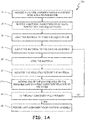
- FIG. 1A is a flow chart showing method 10a for manufacturing a cast component.
- Method 10a utilizes a durable, non-wettable core (not shown in FIG. 1 ) in connection with precision movement to create a cast component having internal hollow cavities.
- Forming hollow cavities within cast components through method 10a provides several benefits. Among those benefits are avoiding the manufacturing cost and process time as well as the environmental consequences associated with creating and removing sacrificial cores from cast components through chemical leaching or baking processes.
- Step 12 involves providing a casting assembly.
- the casting assembly includes, at a minimum, a casting mold to define the exterior features of the cast component and a durable, non-wettable core to define the interior features (i.e. one or more hollow cavities) of the cast component.
- the core is positioned relative to the casting mold.
- Step 14 involves providing a material characterized by solid, transition, and liquid phases. The boundaries between each phase are marked by a solidus temperature and a liquidus temperature of the material. The material takes a solid phase when the material temperature is less than or equal to the solidus temperature and takes a liquid phase when the material temperature is greater than or equal to the liquidus temperature.
- the material forms a transition phase characterized by a viscous fluid relative to the material in the liquid phase.
- the material is prepared for casting by heating it until the material is substantially in the liquid phase. Heating the material prior to casting is accomplished by one or more methods well known in the art (e.g., using a combustion or induction furnace).
- the material forms a liquid phase, it is delivered to the casting assembly in step 18. The material is poured into the casting assembly, thus filling at least a portion of the casting assembly.
- step 20 involves cooling the material in the region adjacent the core. In particular, the material is cooled near a portion of the core used to form internal hollow cavities within the cast component and is not necessarily the entire core.
- the material While the material is cooling, its material temperature approaches the liquidus temperature.
- various process parameters are monitored to evaluate the solidification process in step 22.
- the monitored process parameters are the material temperature in the region adjacent to the core, the bulk material temperature, the temperature of the casting mold, the furnace temperature, and other environmental parameters such as ambient temperature and the like.
- the material bounding the core Once the material bounding the core enters the transition phase and the viscosity of the material is sufficient to support the hollow cavities within the material, one of the casting mold and the core is held stationary while the other is moved in a direction relative to the other in step 24a.
- the casting mold is heated in order to reduce a rate of solidification. If the component is fully formed in step 26, the cast component is removed from the casting mold in step 28.
- steps 18 through 24a are repeated until the cast component is fully formed and removed in step 28. Moreover, repeating steps 18 through 24a (or alternatively 24b as described below) occurs when material is periodically supplied to the casting assembly in order to better control the solidification rate of the material.
- FIG. 1B is a flow chart showing method 10b, which is substantially similar to method 10a except method 10b includes step 24b instead of step 24a.
- Step 24b involves moving the casting mold in a first direction relative to the core and moving the core in a second direction relative to the casting mold, the first direction being different than the second direction. Combining the motion of the casting mold and core allows method 10b to be applied to directional solidification processes.
- movement of the casting mold controls the rate and direction of solidification by moving the casting mold from a melting zone (i.e. a furnace) to a solidification zone (i.e. a cooler region adjacent to the furnace).
- the movement of the core controls the formation of hollow cavities within the cast component during the solidification process.
- the core is designed to withstand multiple casting cycles without replacement.
- a core withstanding only a few casting cycles is sufficiently durable if the manufacturing costs (e.g., material cost, manufacturing time, labor) are reduced by eliminating chemical leaching and/or baking steps associated with sacrificial cores.
- the core is constructed from one or more materials that produce a non-wettable surface (i.e. a surface that inhibits the ability of a liquid to wet or cover the surface). Additionally, the core material has thermal shock resistance and erosion resistance sufficient to enable the core to survive multiple casting cycles that produce cast components within manufacturing tolerances.
- the core is constructed from silicide or ternary intermetallic metals (e.g., MAX phase materials) with appropriate ceramic coatings for casting higher temperature materials such as iron and nickel base alloys.
- ceramic coatings include alumina and yittra-stabilized zirconia based coatings.
- thin metallic sheets with thermal barrier and/or environmental coatings are used to create thin cast components that are not achievable with brittle materials.
- Movement of the core and/or the casting mold is a repeated motion or pattern of motion used to define the desired shape of the cast component. Depending on the motion of the core and/or casting mold, voids, porosity, foam structures, and lattice structures are created. Such motion can be controlled remotely or with embedded digital motors and/or actuators.
- the casting material is a metal (e.g., aluminum, carbon steel, and nickel and associated alloys).
- methods 10a and 10b can be applied to other materials such as organic and inorganic salts, paraffin wax, plastics, or food items such as confectionary sugar syrup or gelatins.
- the resulting cast component i.e. foam, lattice, cored material
- the resulting cast component can be used for cosmetic reasons.
- methods 10a and/or 10b apply to conventional casting, die-casting, and directional solidification casting processes as will be described in greater detail below.
- casting molds and cores will be described in the following embodiments with a particular geometry, it is understood that other geometries can be implemented so long as the geometries are compatible with methods 10a and/or 10b as described generally above.
- FIG. 2A is a schematic plan view of durable, non-wettable core 30 shown in an extended state.
- Core 30 includes structures 32, 34, and 36.
- Structure 32 extends along axis 33, which intersects the geometric center of structure 32.
- Structure 34 has one or more protrusions 34a, and structure 36 has one or more protrusions 36a for forming hollow cavities within a cast component (not shown in FIG. 2A ).
- Structures 34 and 36 are attached to structure 32 in a manner that allows structures 34 and 36 to move or retract relative to structure 32. As such, structure 32 is generally disposed between structures 34 and 36. In some embodiments, structures 34 and 36 are attached to opposing faces of structure 32.
- FIG. 2B is a schematic showing the casting of a component using core 30 from FIG. 2A in a conventional casting process.
- Core 30 includes structures 32, 34, and 36 having axis 33 and protrusions 34a and 36a as discussed above.
- core 30 is assembled within casting assembly 38 which also includes casting mold 40.
- Core 30, configured in an extended position is positioned relative to mold 40.
- core 30 is inserted within mold 40 such that axis 33 of structure 32 intersects a geometric center of mold 40.
- core 30 is positioned at an angle relative to mold 40 and/or offset from the geometric center of mold 40 as necessary to produce a cast component having the desired geometry.
- material 42 is melted and poured into casting assembly 38 in accordance with method 10a. After material 42 conforms to the surfaces of core 30 and mold 40, casting assembly 38 is placed in a cooling environment. Omnidirectional heat loss from material 42 through casting assembly 38 causes material 42, initially in a liquid phase, to form a transition phase. Portions of material 42 adjacent to mold 40 but that is not contacting mold 30 can solidify. When the remaining portions of material 42 adjacent to core 30 are relatively viscous (i.e., form transition phase), core 30 is removed.
- structures 34 and 36 Prior to removal, structures 34 and 36 are retracted relative to structure 32 of core 30 as depicted in FIG. 2C .
- structure 34 slides along a mating face of structure 32 in a direction indicated by arrow 44 towards and generally perpendicular to axis 33 while structure 36 moves in an opposing direction along another mating face of structure 32 as indicated by arrow 46.
- core 30 takes a retracted form that allows core 30 to be removed from casting assembly 38.
- FIG. 2D is a schematic showing the creation of hollow cavities 50 and 52 by withdrawing core 30 in a withdrawal direction indicated by arrow 48 from casting assembly 38.
- the retracted state of core 30 permits structures 32, 34, and 36 to be withdrawn from casting assembly 38 without interfering with solidifying material 42.
- protrusions 36a and 34a (not shown in FIG. 2D ) have a triangular cross-section as shown in FIG. 2D and form similarly-shaped hollow cavities 50 and 52, respectively.
- other protruding shapes are possible so long as the viscosity of material 42 adjacent to core 30 immediately prior to withdrawal is sufficient to support the internal features (e.g., hollow cavities 50 and 52) once core 30 is removed.
- the required viscosity of material 42 depends on the size of the internal feature to be formed and the properties and temperature of material 42 when core 30 is withdrawn from material 42.
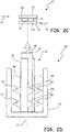
- FIGs. 3A and 3B are schematics of casting assembly 54 showing the creation of hollow cavities 56 (see FIG. 3B ) using durable, non-wettable, core 58 coupled with directional solidification.
- Core 58 includes shaft 60, plate 62, and at least one protrusion 64.
- Shaft 60 extends along axis 66, which intersects the geometric center of shaft 60.
- Shaft 60 has opposing ends 68 and 70.
- Plate 62 is attached to shaft 60 at end 70 and has at least one protrusion 64 extending therefrom in a direction opposite shaft 60.
- core 58 has a plurality of protrusions 64 extending from plate 62, being spaced along plate 62 so as to form a comb-like shape.
- Casting mold 72 includes side mold 74 that encircles core 58 and chill plate 76 disposed at an end of casting mold 72 abutting and/or attached to side mold 74.
- material 78 is supplied to casting assembly 54.
- material 78 fills the interior volume of casting assembly 54 defined by casting mold 72 and core 58.
- material 78 is fed to casting assembly 54 at an average feed rate. In such embodiments, the feed rate can be characterized by periodically supplying material 78 to casting assembly 54 to better control the solidification of material 78 in casting assembly 54.
- Chill pate 76 is configured to cool material 78 to promote solidification of material 78 while side mold 74 is insulated and/or heated to prevent premature solidification of material 78.
- chill plate 76 is a water-cooled metal plate (e.g., a water-cooled copper plate). This arrangement of casting mold 72 causes material 78 to solidify adjacent to chill plate 76 while material 78 remains in a liquid or transition phase elsewhere within casting mold 72. Thus, material 78 forms solid phase 78a, transition phase 78b, and liquid phase 78c, in sequential order, extending from a region adjacent chill plate 76.
- casting mold 72 is moved relative to core 58 when material 78 within transition phase 78b has a viscosity sufficient to form hollow cavities 56.
- Solid phase 78a and transition phase 78b grow to encompass a substantial portion of protrusions 64 of core 58. Because solid phase 78a generally causes material 78 to contract, distal ends of protrusions 64 (i.e. and end opposite plate 62) are tapered in some embodiments to counteract this contraction and promote relative movement of casting mold 72 relative to core 58.
- casting mold 72 is moved in a direction indicated by arrow 80, which is generally parallel to axis 66 of core 58.
- casting mold 72 is typically moved from a melting region to a solidification region.
- the melting region e.g., the interior of a furnace
- the solidification region e.g., the exterior of a furnace
- the solidification of material 78 promotes directional grain structures in solid phase 78a and hollow cavities 56 are formed without using chemical leaching or baking processes to remove core 58.
- FIG. 4 is a schematic showing the creation of staggered hollow cavities 81a and 81b using casting assembly 54 as previously described above.
- core 58 is moved in directions indicated by bi-direction arrow 83a and/or bi-directional arrow 83b.
- core 58 is moved in a direction that is perpendicular to the withdrawal direction of casting mold 72 indicated by arrow 80.
- hollow cavities 81a and 81b are formed in a staggered pattern.
- the sizes of hollow cavities 81a and 81b are determined by the rate at which core 58 and casting mold 72 are moving relative to one another.
- FIGs. 5A and 5B are schematic views of casting assembly 82 showing the creation of hollow cavities 84 using durable, non-wettable core 86.
- Casting assembly 82 includes core 86 and casting mold 87.
- Core 86 includes hollow shaft 88 and spokes 90 supporting volute 92.
- Hollow shaft 88 extends along axis 94, which intersects a geometric center of core 86, and has opposing ends 96 and 98 (see FIG. 5B ).
- Spokes 90 extend from end 96 of hollow shaft 88 in an outward and generally perpendicular direction relative to axis 94.
- Casting mold 87 includes side mold 100 and chill plate 102, each being substantially similar to side mold 74 and chill plate 76.
- material 104 is supplied to casting assembly 82.
- material 104 fills the interior volume of casting assembly 82 defined by casting mold 87 and core 86.
- material 104 is fed to casting assembly 82 at an average feed rate.
- the feed rate can be characterized by periodically supplying material 104 to casting assembly 82 to better control the solidification of material 104 in casting assembly 82.
- Material 104 forms solid phase 104a, transition phase 104b, and liquid phase 104c as a result of chill plate 102 cooling material 104 from an end of casting mold 87.
- spokes 90 are shaped (e.g., tapered) such that material 104 readily flows along spokes 90 and through volute 92.
- FIG. 5B shows casting mold 87 moving relative to core 86.
- Casting mold 87 movement occurs when material 104 within transition phase 104b has a viscosity sufficient to form hollow cavities 84.
- Continued cooling of material 104 by chill plate 102 causes solid phase 104a and transition phase 104b to grow until phases 104a and 104b encompass a substantial portion of volute 92.
- solid phase 104a generally causes material 104 to contract
- edges of volute 92 facing chill plate 102 are tapered in some embodiments to counteract this contraction and promote relative movement of casting mold 87 relative to core 86.
- casting mold 87 is moved in a direction indicated by arrow 106, which is generally parallel to axis 94 of core 86.
- casting mold 87 is typically moved from a melting region to a solidification region.
- the melting region e.g., the interior of a furnace
- the solidification region e.g., the exterior of a furnace
- the solidification of material 104 promotes directional grain structures in solid phase 104a and hollow cavities 84 are formed without using chemical leaching or baking processes to remove core 86.
- the end result of this process is to cast a spiral roll of sheet metal without using a consumable core. In a directional solidification process this will allow casting of long single crystal sheet metal, not attainable by solidification furnaces currently available.
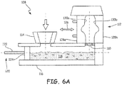
- FIG. 6A is schematic of casting assembly 108 showing the creation of a die-cast component using perforated core plate 110 and casting mold 112.
- Casting assembly 108 includes core plate 110, casting mold 112, material inlet 114, and shot tube 116.
- Core plate 110 is disposed between casting mold 112 and shot tube 116.
- material 118 is fed through inlet 114 into shot tube 116.
- Piston 120 includes shaft 122 and head 124. Actuating piston 120 along shot tube 116 in a direction towards core plate 110 forces material 118 through core plate 110 into casting mold 112.
- casting mold 112 is moved parallel to core plate 110 as indicated by bi-directional arrow 126.
- an oscillating casting mold 112 creates porosity within material 118, which has a transition phase as it flows through core plate 110 and solidifies within casting mold 112.
- the porosity within material 118 increases as the oscillating motion of casting mold 112 increases.
- the porosity within material 118 decreases as the oscillating motion of casting mold 112 decreases.
- casting mold 112 is split in at least two halves 128a and 128b that have mating surfaces. In some embodiments, halves 128a and 128b mate along a common plane. Internal surfaces 130a and 130b of each mold half 128a and 128b, respectively, define the exterior surfaces of a cast component (not shown in FIG. 6A ).
- FIG. 6B is a schematic plan view of core plate 110 of FIG. 6A .
- core plate 110 When viewed as shown in FIG. 6B , core plate 110 has a cross-section that conforms to shot tube 116.
- Core plate 110 includes at least one passage 132 through which material 118 traverses core plate 110 from shot tube 116 to casting mold 112.
- core plate 110 includes a plurality of passages 132, although multiple passages 132 are not required.
- a method of manufacturing includes providing a casting assembly, providing a material having solid, transition, and liquid phases, heating the material to form the liquid phase, supplying the material to the casting assembly, cooling the material, monitoring the solidification of the material from the liquid phase through the transition phase, and moving one of the casting mold or the reusable core in a first direction relative to the other when a substantial portion of the reusable core contacts the transition phase.
- the casting assembly comprises a casting mold and a reusable core inserted within the casting mold.
- the material has a solid phase at a temperature less than or equal to the solidus temperature.
- the material has a transition phase at a temperature between the solidus and liquidus temperatures.
- the material has a liquid phase at a temperature greater than or equal to the liquidus temperature.
- the method of the preceding paragraph can optionally include, additionally and/or alternatively, any one or more of the following features, configurations and/or additional components:
- a further embodiment of any of the foregoing methods can further include removing the reusable core from the casting mold.
- the viscosity of the material adjacent to the reusable core at a time immediately preceding the removal of the core can be sufficient to form one or more hollow cavities within the material.
- a further embodiment of any of the foregoing methods can further include heating the casting assembly during the removal of the core to reduce a rate of solidification of the material.
- the reusable core can further comprise a first structure that extends into the casting mold along a central axis and a second structure attached to the first structure such that the second structure is movable relative to the first structure in a direction substantially perpendicular to the central axis.
- the reusable core can further comprise a protrusion extending from the second structure configured to form a hollow cavity within the material, wherein a distal end of the protrusion can be tapered.
- casting mold can move from a first zone having a first temperature sufficient to form the liquid phase to a second zone having a second temperature sufficient to form a solid phase.
- casting assembly can further comprise a plate forming an end of the casting mold configured to cool the material.
- a further embodiment of any of the foregoing methods can further include forming a unidirectional crystalline structure within the material.
- a further embodiment of any of the foregoing methods can further include forming a passage extending through at least a portion of the material, wherein the passage can be formed by the relative movement of the casting mold to the reusable core.
- the reusable core can comprise a shaft extending in the casting mold along a central axis, a plate having a first face affixed to the shaft and a second face opposite the first face, and a plurality of protrusions extending from the second face, each protrusion having a tapered distal end.
- the reusable core can comprise a hollow shaft extending in the casting mold along a central axis, a plurality of spokes affixed to an outer surface of the hollow shaft that extend outward from and generally perpendicular to the axis, and a volute affixed to the outer surface of the hollow shaft and the plurality of spokes, wherein the volute extends in a circumferential direction about the axis.
- a further embodiment of any of the foregoing methods can further include moving the reusable core in a second direction relative to the casting mold, wherein the second direction is different from the first direction.
- a further embodiment of any of the foregoing methods can further include forming a first plurality of cavities and a second plurality of cavities within the material, wherein the second plurality of cavities can be offset from the first plurality of cavities.
- a method of manufacturing a die-cast component includes providing a casting assembly, providing a material having solid, transition, and liquid phases, and heating the material to for the liquid phase.
- the casting assembly comprises a permanent casting mold having first and second halves that mate along a plane and a core plate rotatably mounted relative to the permanent casting mold.
- the core plate has an axis of rotation parallel to the plane and defines a plurality of passages extending therethrough.
- the method further includes supplying the material to the casting assembly through the plurality of passages of the core plate and controlling the solidification of the material such that the core plate is positioned substantially within the transition phase.
- the material has a solid phase at a temperature less than or equal to the solidus temperature.
- the material has a transition phase at a temperature between the solidus and liquidus temperatures.
- the material has a liquid phase at a temperature greater than or equal to the liquidus temperature.
- the method of the preceding paragraph can optionally include, additionally and/or alternatively, any one or more of the following features, configurations and/or additional components:
- a further embodiment of any of the foregoing methods can further include oscillating the core plate about the axis to form porosity within the material.
Landscapes
- Engineering & Computer Science (AREA)
- Mechanical Engineering (AREA)
- Molds, Cores, And Manufacturing Methods Thereof (AREA)
Abstract
Description
- Conventional casting generally involves pouring liquid metal into a sacrificial mold made from low-cost, consumable materials. The sacrificial mold materials have melting points higher than the liquid metal and are effectively chemically inert for the duration of a single casting process. This casting process is regularly used to produce low-cost, relatively simplistic parts using manual sand casting and to produce high-cost, relatively complex aerospace parts (e.g. blades and vanes) using lost wax investment casting. Although the cost per mold is relatively low, the molds are destroyed during each casting and require reproduction for subsequent castings.
- Die casting generally involves pouring liquid metal into a durable metal mold made from two precision-machined dies. Contrary to conventional casting processes, die casting processes aim to rapidly mass-produce cast parts without reproducing and preparing sacrificial molds. Commonly, this process is used to cast low melting metals (e.g. aluminum and copper). Die casting is also used to cast high melting alloys (e.g. nickel alloys). However, in such processes the die life is further limited.
- Contrary to conventional casting and die casting processes in which the solidification process is largely uncontrolled (i.e. solidification is omnidirectional), directional solidification processes control the location and rate of solidification to form unidirectional grain structures within the solidified metal. In its simplest form, directional solidification of a casting is achieved by progressively depowering heating elements, thereby cooling the casting from one end of the mold to the other. Continuous casting is another form of directional solidification in which liquid metal is poured into a vertically-oriented, water-cooled copper mold. Typically, the copper molds have a cylindrical, square or I-beam cross section and an open-ended bottom. As liquid metal flows through the mold, the metal along the water-cooled surfaces of the mold solidifies and, as the remainder of the metal cools, this process forms long, continuous billets of cast metal. In its most advanced form, directional solidification casting is practiced in conjunction with the investment casting process to form single crystal cast parts. In this process, a mold full of liquid metal is cooled from one end by a water-cooled plate. As the mold and water-cooled plate are slowly moved from a hot zone to a cool zone in the direction of the water-cooled plate, the liquid material solidifies and forms columns of crystal or single crystal in the direction of withdrawal.
- In each casting process, a core can be suspended within the mold to form a hollow cavity. However, when conventional casting or directional investment casting processes are used, the core becomes encapsulated in the solidified material. To remove the core and thereby expose the hollow cavity, a chemical leaching or heating process is used to chemically remove or burn the core. The chemical leaching and/or baking processes destroy the core. When a die casting process is used, the core is susceptible to damage when the cast part is removed from the mold. Moreover, when a continuous casting process is used, the cores are fixed and thus, the castings are limited to fixed cross-sections. Therefore, a need exists for an improved casting process that utilizes reusable cores to improve manufacturing time and reduce manufacturing expense.
- A method of manufacturing includes providing a casting assembly, providing a material having solid, transition, and liquid phases, heating the material to form the liquid phase, supplying the material to the casting assembly, cooling the material, monitoring the solidification of the material from the liquid phase through the transition phase, and moving one of the casting mold or the reusable core in a first direction relative to the other when a substantial portion of the reusable core contacts the transition phase. The casting assembly comprises a casting mold and a reusable core inserted within the casting mold.
- A method of manufacturing a die-cast component includes providing a casting assembly, providing a material having solid, transition, and liquid phases, and heating the material to for the liquid phase. The casting assembly comprises a permanent casting mold having first and second halves that mate along a plane and a core plate rotatably mounted relative to the permanent casting mold. The core plate has an axis of rotation parallel to the plane and defines a plurality of passages extending therethrough. The method further includes supplying the material to the casting assembly through the plurality of passages of the core plate and controlling the solidification of the material such that the core plate is positioned substantially within the transition phase. The material has a solid phase when the material temperature is less than or equal to the solidus temperature. The material has a transition phase when the material temperature is between the solidus and liquidus temperatures. The material has a liquid phase when the material temperature is greater than or equal to the liquidus temperature.
-
-
FIG. 1A is a flow chart showing a method for manufacturing a cast component using a durable, non-wettable core coupled with controlled movement of one or more parts of the casting assembly. -
FIG. 1B is a flow chart showing another method for manufacturing a cast component using a durable, non-wettable core coupled with controlled movement of one or more parts of the casting assembly. -
FIG. 2A is a schematic plan view of a durable, non-wettable core in an extended state. -
FIG. 2B is a schematic showing the casting of a component using the core fromFIG. 2A -
FIG. 2C is a schematic plan view of the core fromFIG. 2A in a retracted state. -
FIG. 2D is a schematic showing the creation of hollow cavities using the durable, non-wettable, core fromFIG. 2C . -
FIGs. 3A and3B are schematics showing the creation of hollow cavities using a durable, non-wettable, core coupled with directional solidification. -
FIG. 4 is a schematic showing the creation of staggered hollow cavities using a durable, non-wettable, core coupled with directional solidification. -
FIG. 5A is a schematic plan view of a durable, non-wettable core having a volute supported by several spokes. -
FIG. 5B is a schematic showing the creation of hollow cavities using the core fromFIG. 3A coupled with directional solidification. -
FIG. 6A is schematic showing the creation of a die-cast component using a perforated core plate. -
FIG. 6B is a schematic plan view of the core plate ofFIG. 5A . - The present invention relates to casting apparatuses and processes, and in particular, to casting apparatuses and processes that couple precision movement with one or more durable, non-wettable cores.
-
FIG. 1A is a flowchart showing method 10a for manufacturing a cast component.Method 10a utilizes a durable, non-wettable core (not shown inFIG. 1 ) in connection with precision movement to create a cast component having internal hollow cavities. Forming hollow cavities within cast components throughmethod 10a provides several benefits. Among those benefits are avoiding the manufacturing cost and process time as well as the environmental consequences associated with creating and removing sacrificial cores from cast components through chemical leaching or baking processes. - Generally,
method 10a includessteps Step 12 involves providing a casting assembly. The casting assembly includes, at a minimum, a casting mold to define the exterior features of the cast component and a durable, non-wettable core to define the interior features (i.e. one or more hollow cavities) of the cast component. To establish the cast component geometry, the core is positioned relative to the casting mold.Step 14 involves providing a material characterized by solid, transition, and liquid phases. The boundaries between each phase are marked by a solidus temperature and a liquidus temperature of the material. The material takes a solid phase when the material temperature is less than or equal to the solidus temperature and takes a liquid phase when the material temperature is greater than or equal to the liquidus temperature. Between the solidus and liquidus temperatures, the material forms a transition phase characterized by a viscous fluid relative to the material in the liquid phase. Followingstep 14, the material is prepared for casting by heating it until the material is substantially in the liquid phase. Heating the material prior to casting is accomplished by one or more methods well known in the art (e.g., using a combustion or induction furnace). Once the material forms a liquid phase, it is delivered to the casting assembly instep 18. The material is poured into the casting assembly, thus filling at least a portion of the casting assembly. Next,step 20 involves cooling the material in the region adjacent the core. In particular, the material is cooled near a portion of the core used to form internal hollow cavities within the cast component and is not necessarily the entire core. While the material is cooling, its material temperature approaches the liquidus temperature. During this time, various process parameters are monitored to evaluate the solidification process instep 22. Among the monitored process parameters are the material temperature in the region adjacent to the core, the bulk material temperature, the temperature of the casting mold, the furnace temperature, and other environmental parameters such as ambient temperature and the like. Once the material bounding the core enters the transition phase and the viscosity of the material is sufficient to support the hollow cavities within the material, one of the casting mold and the core is held stationary while the other is moved in a direction relative to the other instep 24a. In some embodiments, the casting mold is heated in order to reduce a rate of solidification. If the component is fully formed instep 26, the cast component is removed from the casting mold instep 28. However, if the component is not fully formed (i.e. additional hollow cavities are required), steps 18 through 24a are repeated until the cast component is fully formed and removed instep 28. Moreover, repeatingsteps 18 through 24a (or alternatively 24b as described below) occurs when material is periodically supplied to the casting assembly in order to better control the solidification rate of the material. - Alternatively,
FIG. 1B is a flowchart showing method 10b, which is substantially similar tomethod 10a exceptmethod 10b includesstep 24b instead ofstep 24a.Step 24b involves moving the casting mold in a first direction relative to the core and moving the core in a second direction relative to the casting mold, the first direction being different than the second direction. Combining the motion of the casting mold and core allowsmethod 10b to be applied to directional solidification processes. In one embodiment, movement of the casting mold controls the rate and direction of solidification by moving the casting mold from a melting zone (i.e. a furnace) to a solidification zone (i.e. a cooler region adjacent to the furnace). In such an embodiment, the movement of the core controls the formation of hollow cavities within the cast component during the solidification process. - For the core to be successfully implemented in
methods - Movement of the core and/or the casting mold is a repeated motion or pattern of motion used to define the desired shape of the cast component. Depending on the motion of the core and/or casting mold, voids, porosity, foam structures, and lattice structures are created. Such motion can be controlled remotely or with embedded digital motors and/or actuators.
- Typically, the casting material is a metal (e.g., aluminum, carbon steel, and nickel and associated alloys). However,
methods - As will be appreciated by those skilled in the art,
methods 10a and/or 10b apply to conventional casting, die-casting, and directional solidification casting processes as will be described in greater detail below. Although the following casting molds and cores will be described in the following embodiments with a particular geometry, it is understood that other geometries can be implemented so long as the geometries are compatible withmethods 10a and/or 10b as described generally above. -
FIG. 2A is a schematic plan view of durable,non-wettable core 30 shown in an extended state.Core 30 includesstructures Structure 32 extends alongaxis 33, which intersects the geometric center ofstructure 32.Structure 34 has one ormore protrusions 34a, andstructure 36 has one ormore protrusions 36a for forming hollow cavities within a cast component (not shown inFIG. 2A ).Structures structures structure 32 is generally disposed betweenstructures structures structure 32. -
FIG. 2B is a schematic showing the casting of acomponent using core 30 fromFIG. 2A in a conventional casting process.Core 30 includesstructures axis 33 andprotrusions core 30 is assembled within castingassembly 38 which also includes castingmold 40.Core 30, configured in an extended position, is positioned relative tomold 40. In some embodiments,core 30 is inserted withinmold 40 such thataxis 33 ofstructure 32 intersects a geometric center ofmold 40. However, in other embodiments,core 30 is positioned at an angle relative to mold 40 and/or offset from the geometric center ofmold 40 as necessary to produce a cast component having the desired geometry. - To form a cast component,
material 42 is melted and poured into castingassembly 38 in accordance withmethod 10a. Aftermaterial 42 conforms to the surfaces ofcore 30 andmold 40, castingassembly 38 is placed in a cooling environment. Omnidirectional heat loss frommaterial 42 through castingassembly 38 causesmaterial 42, initially in a liquid phase, to form a transition phase. Portions ofmaterial 42 adjacent to mold 40 but that is not contactingmold 30 can solidify. When the remaining portions ofmaterial 42 adjacent tocore 30 are relatively viscous (i.e., form transition phase),core 30 is removed. - Prior to removal,
structures core 30 as depicted inFIG. 2C . In some embodiments,structure 34 slides along a mating face ofstructure 32 in a direction indicated byarrow 44 towards and generally perpendicular toaxis 33 whilestructure 36 moves in an opposing direction along another mating face ofstructure 32 as indicated by arrow 46. Thus,core 30 takes a retracted form that allowscore 30 to be removed from castingassembly 38. -
FIG. 2D is a schematic showing the creation ofhollow cavities core 30 in a withdrawal direction indicated byarrow 48 from castingassembly 38. As can be seen inFIG. 2D , the retracted state ofcore 30permits structures assembly 38 without interfering with solidifyingmaterial 42. In some embodiments,protrusions FIG. 2D ) have a triangular cross-section as shown inFIG. 2D and form similarly-shapedhollow cavities material 42 adjacent tocore 30 immediately prior to withdrawal is sufficient to support the internal features (e.g.,hollow cavities 50 and 52) oncecore 30 is removed. The required viscosity ofmaterial 42 depends on the size of the internal feature to be formed and the properties and temperature ofmaterial 42 whencore 30 is withdrawn frommaterial 42. -
FIGs. 3A and3B are schematics of castingassembly 54 showing the creation of hollow cavities 56 (seeFIG. 3B ) using durable, non-wettable,core 58 coupled with directional solidification.Core 58 includesshaft 60,plate 62, and at least oneprotrusion 64.Shaft 60 extends alongaxis 66, which intersects the geometric center ofshaft 60.Shaft 60 has opposing ends 68 and 70.Plate 62 is attached toshaft 60 atend 70 and has at least oneprotrusion 64 extending therefrom in a direction oppositeshaft 60. In some embodiments,core 58 has a plurality ofprotrusions 64 extending fromplate 62, being spaced alongplate 62 so as to form a comb-like shape. To form castingassembly 54,core 58 is positioned relative to castingmold 72. Castingmold 72 includesside mold 74 that encirclescore 58 andchill plate 76 disposed at an end of castingmold 72 abutting and/or attached toside mold 74. - To form a cast component,
material 78 is supplied to castingassembly 54. In some embodiments,material 78 fills the interior volume of castingassembly 54 defined by castingmold 72 andcore 58. In other embodiments,material 78 is fed to castingassembly 54 at an average feed rate. In such embodiments, the feed rate can be characterized by periodically supplyingmaterial 78 to castingassembly 54 to better control the solidification ofmaterial 78 in castingassembly 54. -
Chill pate 76 is configured to coolmaterial 78 to promote solidification ofmaterial 78 whileside mold 74 is insulated and/or heated to prevent premature solidification ofmaterial 78. In some embodiments,chill plate 76 is a water-cooled metal plate (e.g., a water-cooled copper plate). This arrangement of castingmold 72causes material 78 to solidify adjacent to chillplate 76 whilematerial 78 remains in a liquid or transition phase elsewhere within castingmold 72. Thus,material 78 formssolid phase 78a,transition phase 78b, andliquid phase 78c, in sequential order, extending from a regionadjacent chill plate 76. - Referring now to
FIG. 3B , castingmold 72 is moved relative tocore 58 whenmaterial 78 withintransition phase 78b has a viscosity sufficient to formhollow cavities 56.Solid phase 78a andtransition phase 78b grow to encompass a substantial portion ofprotrusions 64 ofcore 58. Becausesolid phase 78a generally causesmaterial 78 to contract, distal ends of protrusions 64 (i.e. and end opposite plate 62) are tapered in some embodiments to counteract this contraction and promote relative movement of castingmold 72 relative tocore 58. Furthermore, castingmold 72 is moved in a direction indicated byarrow 80, which is generally parallel toaxis 66 ofcore 58. To further promote solidification ofmaterial 78, castingmold 72 is typically moved from a melting region to a solidification region. The melting region (e.g., the interior of a furnace) has a temperature sufficient to maintainmaterial 78 inliquid phase 78c while the solidification region (e.g., the exterior of a furnace), has a temperature sufficient to maintainmaterial 78 insolid phase 78a. Thus, the solidification ofmaterial 78 promotes directional grain structures insolid phase 78a andhollow cavities 56 are formed without using chemical leaching or baking processes to removecore 58. -
FIG. 4 is a schematic showing the creation of staggeredhollow cavities casting assembly 54 as previously described above. However, instead of restrainingcore 58 and moving castingmold 72 to form hollow cavities 56 (seeFIG. 3B ),core 58 is moved in directions indicated bybi-direction arrow 83a and/orbi-directional arrow 83b. In some embodiments,core 58 is moved in a direction that is perpendicular to the withdrawal direction of castingmold 72 indicated byarrow 80. Thus, by moving both castingmold 72 andcore 58,hollow cavities hollow cavities core 58 and castingmold 72 are moving relative to one another. -
FIGs. 5A and5B are schematic views of castingassembly 82 showing the creation ofhollow cavities 84 using durable,non-wettable core 86.Casting assembly 82 includescore 86 and castingmold 87.Core 86 includeshollow shaft 88 andspokes 90 supportingvolute 92.Hollow shaft 88 extends alongaxis 94, which intersects a geometric center ofcore 86, and has opposing ends 96 and 98 (seeFIG. 5B ).Spokes 90 extend fromend 96 ofhollow shaft 88 in an outward and generally perpendicular direction relative toaxis 94. Castingmold 87 includes side mold 100 andchill plate 102, each being substantially similar toside mold 74 andchill plate 76. - To form a cast component,
material 104 is supplied to castingassembly 82. In some embodiments,material 104 fills the interior volume of castingassembly 82 defined by castingmold 87 andcore 86. In other embodiments,material 104 is fed to castingassembly 82 at an average feed rate. In such embodiments, the feed rate can be characterized by periodically supplyingmaterial 104 to castingassembly 82 to better control the solidification ofmaterial 104 in castingassembly 82.Material 104 forms solid phase 104a,transition phase 104b, andliquid phase 104c as a result ofchill plate 102cooling material 104 from an end of castingmold 87. In any embodiment,spokes 90 are shaped (e.g., tapered) such thatmaterial 104 readily flows alongspokes 90 and throughvolute 92. - In a process similar to the directional casting process described in
FIGs. 3A and3B ,FIG. 5B shows castingmold 87 moving relative tocore 86. Castingmold 87 movement occurs whenmaterial 104 withintransition phase 104b has a viscosity sufficient to formhollow cavities 84. Continued cooling ofmaterial 104 bychill plate 102 causes solid phase 104a andtransition phase 104b to grow untilphases 104a and 104b encompass a substantial portion ofvolute 92. Because solid phase 104a generally causesmaterial 104 to contract, edges ofvolute 92 facingchill plate 102 are tapered in some embodiments to counteract this contraction and promote relative movement of castingmold 87 relative tocore 86. In some embodiments, castingmold 87 is moved in a direction indicated byarrow 106, which is generally parallel toaxis 94 ofcore 86. To further promote solidification ofmaterial 104, castingmold 87 is typically moved from a melting region to a solidification region. The melting region (e.g., the interior of a furnace) has a temperature sufficient to maintain material 104 inliquid phase 104c while the solidification region (e.g., the exterior of a furnace), has a temperature sufficient to maintain material 104 in solid phase 104a. Thus, the solidification ofmaterial 104 promotes directional grain structures in solid phase 104a andhollow cavities 84 are formed without using chemical leaching or baking processes to removecore 86. The end result of this process is to cast a spiral roll of sheet metal without using a consumable core. In a directional solidification process this will allow casting of long single crystal sheet metal, not attainable by solidification furnaces currently available. -
FIG. 6A is schematic of castingassembly 108 showing the creation of a die-cast component usingperforated core plate 110 and castingmold 112.Casting assembly 108 includescore plate 110, castingmold 112,material inlet 114, and shottube 116.Core plate 110 is disposed between castingmold 112 and shottube 116. To form a cast component,material 118 is fed throughinlet 114 intoshot tube 116.Piston 120 includesshaft 122 andhead 124.Actuating piston 120 alongshot tube 116 in a direction towardscore plate 110 forces material 118 throughcore plate 110 into castingmold 112. Asmaterial 118 is fed throughcore plate 110, castingmold 112 is moved parallel tocore plate 110 as indicated bybi-directional arrow 126. Thus, anoscillating casting mold 112 creates porosity withinmaterial 118, which has a transition phase as it flows throughcore plate 110 and solidifies within castingmold 112. The porosity withinmaterial 118 increases as the oscillating motion of castingmold 112 increases. Conversely, the porosity withinmaterial 118 decreases as the oscillating motion of castingmold 112 decreases. To facilitate removal of the cast component (not shown inFIG. 6A ), castingmold 112 is split in at least twohalves halves Internal surfaces mold half FIG. 6A ). -
FIG. 6B is a schematic plan view ofcore plate 110 ofFIG. 6A . When viewed as shown inFIG. 6B ,core plate 110 has a cross-section that conforms to shottube 116.Core plate 110 includes at least onepassage 132 through whichmaterial 118 traversescore plate 110 fromshot tube 116 to castingmold 112. In some embodiments,core plate 110 includes a plurality ofpassages 132, althoughmultiple passages 132 are not required. - The following are non-exclusive descriptions of possible embodiments of the present invention.
- A method of manufacturing includes providing a casting assembly, providing a material having solid, transition, and liquid phases, heating the material to form the liquid phase, supplying the material to the casting assembly, cooling the material, monitoring the solidification of the material from the liquid phase through the transition phase, and moving one of the casting mold or the reusable core in a first direction relative to the other when a substantial portion of the reusable core contacts the transition phase. The casting assembly comprises a casting mold and a reusable core inserted within the casting mold. The material has a solid phase at a temperature less than or equal to the solidus temperature. The material has a transition phase at a temperature between the solidus and liquidus temperatures. The material has a liquid phase at a temperature greater than or equal to the liquidus temperature.
- The method of the preceding paragraph can optionally include, additionally and/or alternatively, any one or more of the following features, configurations and/or additional components:
- A further embodiment of the foregoing method, wherein the reusable core can move relative to the casting mold.
- A further embodiment of any of the foregoing methods can further include removing the reusable core from the casting mold. The viscosity of the material adjacent to the reusable core at a time immediately preceding the removal of the core can be sufficient to form one or more hollow cavities within the material.
- A further embodiment of any of the foregoing methods can further include heating the casting assembly during the removal of the core to reduce a rate of solidification of the material.
- A further embodiment of any of the foregoing methods, wherein the reusable core can further comprise a first structure that extends into the casting mold along a central axis and a second structure attached to the first structure such that the second structure is movable relative to the first structure in a direction substantially perpendicular to the central axis.
- A further embodiment of any of the foregoing methods, wherein the reusable core can further comprise a protrusion extending from the second structure configured to form a hollow cavity within the material, wherein a distal end of the protrusion can be tapered.
- A further embodiment of any of the foregoing methods wherein the casting mold can move relative to the reusable core, and wherein during the solidification of the material, a substantial portion of the reusable core can be immersed in the transition phase.
- A further embodiment of any of the foregoing methods, wherein the casting mold can move from a first zone having a first temperature sufficient to form the liquid phase to a second zone having a second temperature sufficient to form a solid phase.
- A further embodiment of any of the foregoing methods, wherein the casting assembly can further comprise a plate forming an end of the casting mold configured to cool the material.
- A further embodiment of any of the foregoing methods can further include forming a unidirectional crystalline structure within the material.
- A further embodiment of any of the foregoing methods can further include forming a passage extending through at least a portion of the material, wherein the passage can be formed by the relative movement of the casting mold to the reusable core.
- A further embodiment of any of the foregoing methods, wherein the reusable core can comprise a shaft extending in the casting mold along a central axis, a plate having a first face affixed to the shaft and a second face opposite the first face, and a plurality of protrusions extending from the second face, each protrusion having a tapered distal end.
- A further embodiment of any of the foregoing methods, wherein the reusable core can comprise a hollow shaft extending in the casting mold along a central axis, a plurality of spokes affixed to an outer surface of the hollow shaft that extend outward from and generally perpendicular to the axis, and a volute affixed to the outer surface of the hollow shaft and the plurality of spokes, wherein the volute extends in a circumferential direction about the axis.
- A further embodiment of any of the foregoing methods can further include moving the reusable core in a second direction relative to the casting mold, wherein the second direction is different from the first direction.
- A further embodiment of any of the foregoing methods, wherein the second direction can be substantially perpendicular to the first direction.
- A further embodiment of any of the foregoing methods can further include forming a first plurality of cavities and a second plurality of cavities within the material, wherein the second plurality of cavities can be offset from the first plurality of cavities.
- A further embodiment of any of the foregoing methods, wherein the material can be periodically supplied to the casting assembly.
- A method of manufacturing a die-cast component includes providing a casting assembly, providing a material having solid, transition, and liquid phases, and heating the material to for the liquid phase. The casting assembly comprises a permanent casting mold having first and second halves that mate along a plane and a core plate rotatably mounted relative to the permanent casting mold. The core plate has an axis of rotation parallel to the plane and defines a plurality of passages extending therethrough. The method further includes supplying the material to the casting assembly through the plurality of passages of the core plate and controlling the solidification of the material such that the core plate is positioned substantially within the transition phase. The material has a solid phase at a temperature less than or equal to the solidus temperature. The material has a transition phase at a temperature between the solidus and liquidus temperatures. The material has a liquid phase at a temperature greater than or equal to the liquidus temperature.
- The method of the preceding paragraph can optionally include, additionally and/or alternatively, any one or more of the following features, configurations and/or additional components:
- A further embodiment of any of the foregoing methods can further include oscillating the core plate about the axis to form porosity within the material.
- While the invention has been described with reference to an exemplary embodiment(s), it will be understood by those skilled in the art that various changes may be made without departing from the scope of the invention. In addition, many modifications may be made to adapt a particular situation or material to the teachings of the invention without departing from the essential scope thereof. Therefore, it is intended that the invention not be limited to the particular embodiment(s) disclosed, but that the invention will include all embodiments falling within the scope of the appended claims.
Claims (15)
- A method of manufacturing includes:providing a casting assembly comprising:a casting mold; anda reusable core (58) inserted within the casting mold;providing a material (78) that has a solidus temperature and a liquidus temperature, wherein the material has a solid phase at a temperature less than or equal to the solidus temperature, a transition phase at a temperature between the solidus and liquidus temperatures, and a liquid phase at a temperature greater than or equal to the liquidus temperature;heating the material (78) to form the liquid phase;supplying the material (78) to the casting assembly;cooling the material (78);monitoring a solidification of the material (78) from the liquid phase through the transition phase; andmoving one of the casting mold or the reusable core (58) in a first direction relative to the other when a substantial portion of the reusable core (58) contacts the material (78) in the transition phase.
- The method of claim 1, wherein the reusable core (58) moves relative to the casting mold.
- The method of claim 2 and further including:removing the reusable core (58) from the casting mold, wherein a viscosity of the material (78) surrounding the reusable core (58) at a time immediately preceding the removal of the core is sufficient to form one or more hollow cavities within the material (78).
- The method of claim 3 and further including:heating the casting assembly during the removal of the core (58) to reduce a rate of solidification of the material (78).
- The method of claim 2, wherein:the reusable core (58) comprises:a first structure that extends into the casting mold along a central axis; anda second structure attached to the first structure such that the second structure is movable relative to the first structure in a direction substantially perpendicular to the central axis, and whereinthe reusable core (58) further comprises:a protrusion extending from the second structure configured to form a hollow cavity within the material, wherein a distal end of the protrusion is tapered.
- The method of any preceding claim, wherein the casting mold moves relative to the reusable core (58), and wherein during the solidification of the material, a substantial portion of the reusable core is immersed in the transition phase, and preferably wherein the material is periodically supplied to the casting assembly
- The method of claim 6, wherein the casting mold moves from a first zone having a first temperature sufficient to form the liquid phase to a second zone having a second temperature sufficient to form the solid phase.
- The method of claim 6, wherein:the casting assembly further comprises:a plate forming an end of the casting mold configured to cool the material.
- The method of claim 8 and further including:forming a unidirectional crystalline structure within the material.
- The method of claim 6 and further including:forming a passage extending through at least a portion of the material, wherein the passage is formed by the relative movement of the casting mold to the reusable core.
- The method of claim 6, wherein:the reusable core (58) comprises:a shaft extending in the casting mold along a central axis;a plate having a first face affixed to the shaft and a second face opposite the first face; anda plurality of protrusions extending from the second face, each protrusion having a tapered distal end.
- The method of claim 6, wherein:the reusable core (58) comprises:a hollow shaft extending in the casting mold along a central axis;a plurality of spokes affixed to an outer surface of the hollow shaft that extend outward from and generally perpendicular to the axis; anda volute affixed to the outer surface of the hollow shaft and the plurality of spokes, wherein the volute extends in a circumferential direction about the axis.
- The method of claim 6 and further including:moving the reusable core (58) in a second direction relative to the casting mold, wherein the second direction is different from the first direction.
- The method of claim 13, wherein the second direction is substantially perpendicular to the first direction.
- The method of claim 14 and further including:forming a first plurality of cavities and a second plurality of cavities within the material, wherein the second plurality of cavities are offset from the first plurality of cavities.
Applications Claiming Priority (1)
| Application Number | Priority Date | Filing Date | Title |
|---|---|---|---|
| US14/695,291 US20160311016A1 (en) | 2015-04-24 | 2015-04-24 | Casting with reusable precision, motion-controlled, withdrawable cores |
Publications (1)
| Publication Number | Publication Date |
|---|---|
| EP3085473A1 true EP3085473A1 (en) | 2016-10-26 |
Family
ID=55794868
Family Applications (1)
| Application Number | Title | Priority Date | Filing Date |
|---|---|---|---|
| EP16165915.6A Withdrawn EP3085473A1 (en) | 2015-04-24 | 2016-04-19 | Casting with reusable, precision, motion-controlled, withdrawable cores |
Country Status (2)
| Country | Link |
|---|---|
| US (1) | US20160311016A1 (en) |
| EP (1) | EP3085473A1 (en) |
Citations (5)
| Publication number | Priority date | Publication date | Assignee | Title |
|---|---|---|---|---|
| US2118097A (en) * | 1936-08-19 | 1938-05-24 | John Hoiroyd & Company Ltd | Machine for casting hollow bodies |
| GB543810A (en) * | 1940-09-27 | 1942-03-13 | Glacier Co Ltd | Improved method of, and apparatus for, casting bodies of metal with cored holes |
| GB612374A (en) * | 1945-11-07 | 1948-11-11 | Applic Mecaniques Pour L Autom | Improvements relating to die casting |
| US4779665A (en) * | 1982-08-16 | 1988-10-25 | General Motors Corporation | Die casting apparatus and process comprising in-die plunger densification to form a bore through a product casting |
| US4779666A (en) * | 1982-06-23 | 1988-10-25 | General Motors Corporation | Die casting process and apparatus comprising in-die plunger densification |
-
2015
- 2015-04-24 US US14/695,291 patent/US20160311016A1/en not_active Abandoned
-
2016
- 2016-04-19 EP EP16165915.6A patent/EP3085473A1/en not_active Withdrawn
Patent Citations (5)
| Publication number | Priority date | Publication date | Assignee | Title |
|---|---|---|---|---|
| US2118097A (en) * | 1936-08-19 | 1938-05-24 | John Hoiroyd & Company Ltd | Machine for casting hollow bodies |
| GB543810A (en) * | 1940-09-27 | 1942-03-13 | Glacier Co Ltd | Improved method of, and apparatus for, casting bodies of metal with cored holes |
| GB612374A (en) * | 1945-11-07 | 1948-11-11 | Applic Mecaniques Pour L Autom | Improvements relating to die casting |
| US4779666A (en) * | 1982-06-23 | 1988-10-25 | General Motors Corporation | Die casting process and apparatus comprising in-die plunger densification |
| US4779665A (en) * | 1982-08-16 | 1988-10-25 | General Motors Corporation | Die casting apparatus and process comprising in-die plunger densification to form a bore through a product casting |
Also Published As
| Publication number | Publication date |
|---|---|
| US20160311016A1 (en) | 2016-10-27 |
Similar Documents
| Publication | Publication Date | Title |
|---|---|---|
| US6443216B1 (en) | Thermal jacket for a vessel | |
| WO2004022268A1 (en) | Apparatus for producing a metallic slurry material for use in semi-solid forming of shaped parts | |
| US4549599A (en) | Preventing mold and casting cracking in high rate directional solidification processes | |
| AU2001274868A1 (en) | Thermal jacket for a vessel | |
| CN106363151B (en) | A method of preparing copper and iron double metallic composite material | |
| US20110036535A1 (en) | Method of mitigating against thermal contraction induced cracking during casting of a super ni alloy | |
| JP5339764B2 (en) | Casting method | |
| CN103354768B (en) | Cooling agent for casting molten metal molds continuously controls and blade system | |
| EP2551038B1 (en) | Die casting system and method | |
| CN101439401A (en) | Liquid metal directional casting apparatus and process | |
| JP2013507255A (en) | Control pin and spout system for heating molten metal supply spout structure | |
| US20170216912A1 (en) | Apparatus for casting multiple components using a directional solidification process | |
| EP0104794B1 (en) | Method of casting a one-piece wheel | |
| EP3085473A1 (en) | Casting with reusable, precision, motion-controlled, withdrawable cores | |
| EP3292926B1 (en) | Designing method for a baffle for use with an array of shell moulds in a directional solidification casting apparatus | |
| EP2450131B1 (en) | Melting unit for a die casting system | |
| CN104139175B (en) | Composite geometry designs for the crystal grain starter motor in BRIDGMAN investment casting process | |
| CN104801694A (en) | Casting method and cast article | |
| US6263951B1 (en) | Horizontal rotating directional solidification | |
| CN113165057B (en) | Ingot casting molds for continuous casting of aluminum and aluminum alloys | |
| JP6917964B2 (en) | Aluminum alloy casting and its manufacturing method | |
| US20090218067A1 (en) | Lost-wax method associated with piezocrystallization and a device for carrying out said method | |
| EP1900455A1 (en) | Semi-solid casting method and charge | |
| CN106451960A (en) | Production method of motor shell | |
| JP2010227965A (en) | Method for controlling solidification of casting |
Legal Events
| Date | Code | Title | Description |
|---|---|---|---|
| PUAI | Public reference made under article 153(3) epc to a published international application that has entered the european phase |
Free format text: ORIGINAL CODE: 0009012 |
|
| AK | Designated contracting states |
Kind code of ref document: A1 Designated state(s): AL AT BE BG CH CY CZ DE DK EE ES FI FR GB GR HR HU IE IS IT LI LT LU LV MC MK MT NL NO PL PT RO RS SE SI SK SM TR |
|
| AX | Request for extension of the european patent |
Extension state: BA ME |
|
| RIN1 | Information on inventor provided before grant (corrected) |
Inventor name: MARCIN, JOHN JOSEPH Inventor name: SHAH, DILIP M. Inventor name: VERNER, CARL R. Inventor name: BULLIED, STEVEN J. Inventor name: BRENEMAN, RYAN C. |
|
| STAA | Information on the status of an ep patent application or granted ep patent |
Free format text: STATUS: REQUEST FOR EXAMINATION WAS MADE |
|
| 17P | Request for examination filed |
Effective date: 20170327 |
|
| RBV | Designated contracting states (corrected) |
Designated state(s): AL AT BE BG CH CY CZ DE DK EE ES FI FR GB GR HR HU IE IS IT LI LT LU LV MC MK MT NL NO PL PT RO RS SE SI SK SM TR |
|
| STAA | Information on the status of an ep patent application or granted ep patent |
Free format text: STATUS: EXAMINATION IS IN PROGRESS |
|
| 17Q | First examination report despatched |
Effective date: 20170808 |
|
| STAA | Information on the status of an ep patent application or granted ep patent |
Free format text: STATUS: THE APPLICATION IS DEEMED TO BE WITHDRAWN |
|
| 18D | Application deemed to be withdrawn |
Effective date: 20190604 |