EP3085340A1 - Stent delivery system and post release assembly thereof - Google Patents
Stent delivery system and post release assembly thereof Download PDFInfo
- Publication number
- EP3085340A1 EP3085340A1 EP14872805.8A EP14872805A EP3085340A1 EP 3085340 A1 EP3085340 A1 EP 3085340A1 EP 14872805 A EP14872805 A EP 14872805A EP 3085340 A1 EP3085340 A1 EP 3085340A1
- Authority
- EP
- European Patent Office
- Prior art keywords
- release assembly
- stent
- delivery system
- proximal end
- restrain
- Prior art date
- Legal status (The legal status is an assumption and is not a legal conclusion. Google has not performed a legal analysis and makes no representation as to the accuracy of the status listed.)
- Granted
Links
- 230000008878 coupling Effects 0.000 claims description 4
- 238000010168 coupling process Methods 0.000 claims description 4
- 238000005859 coupling reaction Methods 0.000 claims description 4
- 230000000452 restraining effect Effects 0.000 claims description 2
- 230000002792 vascular Effects 0.000 abstract description 5
- 238000000034 method Methods 0.000 description 8
- 229920000642 polymer Polymers 0.000 description 7
- 208000007474 aortic aneurysm Diseases 0.000 description 5
- 239000000463 material Substances 0.000 description 5
- 239000002184 metal Substances 0.000 description 5
- 208000002251 Dissecting Aneurysm Diseases 0.000 description 4
- 239000000853 adhesive Substances 0.000 description 4
- 230000001070 adhesive effect Effects 0.000 description 4
- 206010002895 aortic dissection Diseases 0.000 description 4
- 238000001356 surgical procedure Methods 0.000 description 4
- 239000004677 Nylon Substances 0.000 description 3
- 229920002614 Polyether block amide Polymers 0.000 description 3
- 238000010586 diagram Methods 0.000 description 3
- 229920001778 nylon Polymers 0.000 description 3
- 238000003466 welding Methods 0.000 description 3
- 206010002329 Aneurysm Diseases 0.000 description 2
- 230000003187 abdominal effect Effects 0.000 description 2
- 210000000709 aorta Anatomy 0.000 description 2
- 210000000702 aorta abdominal Anatomy 0.000 description 2
- 238000005452 bending Methods 0.000 description 2
- 201000010099 disease Diseases 0.000 description 2
- 208000037265 diseases, disorders, signs and symptoms Diseases 0.000 description 2
- 210000001105 femoral artery Anatomy 0.000 description 2
- 238000001746 injection moulding Methods 0.000 description 2
- 238000003780 insertion Methods 0.000 description 2
- 230000037431 insertion Effects 0.000 description 2
- 238000003754 machining Methods 0.000 description 2
- 238000002844 melting Methods 0.000 description 2
- 230000008018 melting Effects 0.000 description 2
- 229920001296 polysiloxane Polymers 0.000 description 2
- 230000008439 repair process Effects 0.000 description 2
- 229920000260 silastic Polymers 0.000 description 2
- 208000025494 Aortic disease Diseases 0.000 description 1
- -1 but not limited to Polymers 0.000 description 1
- 230000007547 defect Effects 0.000 description 1
- 230000002950 deficient Effects 0.000 description 1
- 230000003111 delayed effect Effects 0.000 description 1
- 230000000694 effects Effects 0.000 description 1
- 238000002347 injection Methods 0.000 description 1
- 239000007924 injection Substances 0.000 description 1
- 208000014674 injury Diseases 0.000 description 1
- 239000003550 marker Substances 0.000 description 1
- 238000012986 modification Methods 0.000 description 1
- 230000004048 modification Effects 0.000 description 1
- 230000008569 process Effects 0.000 description 1
- 229910001285 shape-memory alloy Inorganic materials 0.000 description 1
- 230000008733 trauma Effects 0.000 description 1
- 230000000472 traumatic effect Effects 0.000 description 1
Images


Classifications
-
- A—HUMAN NECESSITIES
- A61—MEDICAL OR VETERINARY SCIENCE; HYGIENE
- A61F—FILTERS IMPLANTABLE INTO BLOOD VESSELS; PROSTHESES; DEVICES PROVIDING PATENCY TO, OR PREVENTING COLLAPSING OF, TUBULAR STRUCTURES OF THE BODY, e.g. STENTS; ORTHOPAEDIC, NURSING OR CONTRACEPTIVE DEVICES; FOMENTATION; TREATMENT OR PROTECTION OF EYES OR EARS; BANDAGES, DRESSINGS OR ABSORBENT PADS; FIRST-AID KITS
- A61F2/00—Filters implantable into blood vessels; Prostheses, i.e. artificial substitutes or replacements for parts of the body; Appliances for connecting them with the body; Devices providing patency to, or preventing collapsing of, tubular structures of the body, e.g. stents
- A61F2/95—Instruments specially adapted for placement or removal of stents or stent-grafts
- A61F2/954—Instruments specially adapted for placement or removal of stents or stent-grafts for placing stents or stent-grafts in a bifurcation
-
- A—HUMAN NECESSITIES
- A61—MEDICAL OR VETERINARY SCIENCE; HYGIENE
- A61F—FILTERS IMPLANTABLE INTO BLOOD VESSELS; PROSTHESES; DEVICES PROVIDING PATENCY TO, OR PREVENTING COLLAPSING OF, TUBULAR STRUCTURES OF THE BODY, e.g. STENTS; ORTHOPAEDIC, NURSING OR CONTRACEPTIVE DEVICES; FOMENTATION; TREATMENT OR PROTECTION OF EYES OR EARS; BANDAGES, DRESSINGS OR ABSORBENT PADS; FIRST-AID KITS
- A61F2/00—Filters implantable into blood vessels; Prostheses, i.e. artificial substitutes or replacements for parts of the body; Appliances for connecting them with the body; Devices providing patency to, or preventing collapsing of, tubular structures of the body, e.g. stents
- A61F2/95—Instruments specially adapted for placement or removal of stents or stent-grafts
- A61F2/962—Instruments specially adapted for placement or removal of stents or stent-grafts having an outer sleeve
- A61F2/966—Instruments specially adapted for placement or removal of stents or stent-grafts having an outer sleeve with relative longitudinal movement between outer sleeve and prosthesis, e.g. using a push rod
-
- A—HUMAN NECESSITIES
- A61—MEDICAL OR VETERINARY SCIENCE; HYGIENE
- A61F—FILTERS IMPLANTABLE INTO BLOOD VESSELS; PROSTHESES; DEVICES PROVIDING PATENCY TO, OR PREVENTING COLLAPSING OF, TUBULAR STRUCTURES OF THE BODY, e.g. STENTS; ORTHOPAEDIC, NURSING OR CONTRACEPTIVE DEVICES; FOMENTATION; TREATMENT OR PROTECTION OF EYES OR EARS; BANDAGES, DRESSINGS OR ABSORBENT PADS; FIRST-AID KITS
- A61F2/00—Filters implantable into blood vessels; Prostheses, i.e. artificial substitutes or replacements for parts of the body; Appliances for connecting them with the body; Devices providing patency to, or preventing collapsing of, tubular structures of the body, e.g. stents
- A61F2/95—Instruments specially adapted for placement or removal of stents or stent-grafts
- A61F2002/9505—Instruments specially adapted for placement or removal of stents or stent-grafts having retaining means other than an outer sleeve, e.g. male-female connector between stent and instrument
-
- A—HUMAN NECESSITIES
- A61—MEDICAL OR VETERINARY SCIENCE; HYGIENE
- A61F—FILTERS IMPLANTABLE INTO BLOOD VESSELS; PROSTHESES; DEVICES PROVIDING PATENCY TO, OR PREVENTING COLLAPSING OF, TUBULAR STRUCTURES OF THE BODY, e.g. STENTS; ORTHOPAEDIC, NURSING OR CONTRACEPTIVE DEVICES; FOMENTATION; TREATMENT OR PROTECTION OF EYES OR EARS; BANDAGES, DRESSINGS OR ABSORBENT PADS; FIRST-AID KITS
- A61F2/00—Filters implantable into blood vessels; Prostheses, i.e. artificial substitutes or replacements for parts of the body; Appliances for connecting them with the body; Devices providing patency to, or preventing collapsing of, tubular structures of the body, e.g. stents
- A61F2/95—Instruments specially adapted for placement or removal of stents or stent-grafts
- A61F2002/9534—Instruments specially adapted for placement or removal of stents or stent-grafts for repositioning of stents
-
- A—HUMAN NECESSITIES
- A61—MEDICAL OR VETERINARY SCIENCE; HYGIENE
- A61F—FILTERS IMPLANTABLE INTO BLOOD VESSELS; PROSTHESES; DEVICES PROVIDING PATENCY TO, OR PREVENTING COLLAPSING OF, TUBULAR STRUCTURES OF THE BODY, e.g. STENTS; ORTHOPAEDIC, NURSING OR CONTRACEPTIVE DEVICES; FOMENTATION; TREATMENT OR PROTECTION OF EYES OR EARS; BANDAGES, DRESSINGS OR ABSORBENT PADS; FIRST-AID KITS
- A61F2/00—Filters implantable into blood vessels; Prostheses, i.e. artificial substitutes or replacements for parts of the body; Appliances for connecting them with the body; Devices providing patency to, or preventing collapsing of, tubular structures of the body, e.g. stents
- A61F2/95—Instruments specially adapted for placement or removal of stents or stent-grafts
- A61F2/962—Instruments specially adapted for placement or removal of stents or stent-grafts having an outer sleeve
- A61F2/966—Instruments specially adapted for placement or removal of stents or stent-grafts having an outer sleeve with relative longitudinal movement between outer sleeve and prosthesis, e.g. using a push rod
- A61F2002/9665—Instruments specially adapted for placement or removal of stents or stent-grafts having an outer sleeve with relative longitudinal movement between outer sleeve and prosthesis, e.g. using a push rod with additional retaining means
Definitions
- This invention relates generally to the field of medical devices and, in particular, to an aortic stent delivery system used in interventional treatment of an aortic aneurysm (including an aortic dissection).
- the invention is also directed to a second release assembly of the delivery system.
- Aortic diseases such as aortic aneurysm and aortic dissection aneurysm are some of the deadliest and most intractable vascular surgical diseases. Traditionally, the treatment of such diseases relied on open surgery for artificial vessel replacement, which, however, led to significant trauma and high mortality.
- a simple, minimally-invasive interventional surgical procedure has been developed using a covered stent for endovascular repair of aortic dissection.
- the covered stent is introduced from a minimally invasive incision made in the patient's femoral artery and deployed to the aortic defect using a delivery system for protection and repair of the defective vessel.
- delivery systems for use in minimally invasive intervention of aortas for the treatment of aortic aneurysm employ a simple covered stent deployment method involving retrieval of an outer sheath which allows the stent to expand by itself due to its elasticity.
- This method is, however, lack of accuracy in deployment control, because once the stent is improperly located, its self-expansion immediately after the retrieval of the outer sheath will necessitate the use of the highly traumatic open surgery with high fatality for removing the stent.
- the bifurcated abdominal aortic covered stent includes a tubular lattice frame of a shape memory alloy and a cover covering the tubular lattice frame, in which at least two sleeve branches project from a leading portion of the tubular lattice frame.
- the delivery system includes a deployment assembly that is extendable within the tubular lattice frame and comprised of guide wires and flexible sleeves.
- Each flexible sleeve has a leading portion that can extend through the tubular lattice frame into a corresponding one of the sleeve branches in a shape-adapted manner, and each guide wire has one end arranged at a trailing end of a corresponding flexible sleeve and the other end disposed within the flexible sleeve and in connection with the corresponding sleeve branch.
- this delivery system is still not accurate enough in deployment control for the covered stent, and thus makes it necessary to rely on open surgery for removal of the covered stent when it is deployed at an undesired location.
- the present invention addresses the inaccurate deployment control issue of the current delivery systems for use in minimally invasive intervention of aortas for the treatment of aortic aneurysm by presenting a delivery system which allows second release of a proximal end of the stent, i.e., the stent being incompletely deployed with its proximal end being still restrained even after the outer sheath has been retrieved.
- fine adjustments can still be made in the location of the stent to make sure that the stent is accurately deployed.
- the present invention provides a second release assembly for use in a delivery system.
- the second release assembly is disposed at a proximal end of the delivery system and includes, sequentially from a proximal end to a distal end, a proximal fixing part, a restrain part and a control guidewire.
- a proximal end of the restrain part is detachably connected to the proximal fixing part, and a distal end of the restrain part is coupled to the control guidewire.
- the restrain part may be a single part or a combination of several parts.
- the restrain part may be formed of a material which is a polymer or a metal.
- the second release assembly further includes a guide part, the restrain part is configured to extend through the guide part and is thus directed and maintained at a predetermined orientation by the guide part.
- the guide part may also be formed of a material which is a polymer or a metal.
- the second release assembly further includes a coupler for coupling the distal end of the restrain part to the control guidewire, a proximal end of the coupler is in fixed connection with the restrain part or is integrally formed with the restrain part, a distal end of the coupler is in fixed or detachable connection with the control guidewire.
- the coupler may also be formed of a material which is a polymer or a metal.
- the polymer may include, but not limited to, Pebax, Nylon, PC, PE, PP and ABS.
- the restrain part includes a plurality of rods which are circumferentially distributed.
- the restrain part further includes a section defining a bore allowing an inner tube of the delivery system to pass therethrough, and the section is connected to or integrally formed with the plurality of rods.
- the proximal fixing part is provided with a plurality of blind holes which are circumferentially distributed and correspond to the plurality of rods, and each of the plurality of rods is inserted in a corresponding one of the plurality of blind holes.
- the guide part is provided with a plurality of guide holes which are circumferentially distributed and correspond to the plurality of rods, and wherein each of the plurality of rods extends through a corresponding one of the plurality of guide holes.
- the guide part can direct each leg of the restrain part to a desired orientation and maintain it thereat without intersecting or bending. This also facilitates alignment and insertion of the rods of the restrain part into the respective blind holes of the proximal fixing part.
- the present invention provides a stent delivery system including an outer sheath, an inner tube and a stent.
- the delivery system further includes a second release assembly as defined above to control the deployment of a proximal end of the stent.
- the second release assembly extends longitudinally within the outer sheath and receives the inner tube.
- the stent is provided with through holes at the proximal end, and the restrain part of the second release assembly extends through the through holes, thereby restraining the proximal end of the stent.
- the second release assembly can work together with the stent that is provided with the through holes at the proximal end, to restrain the proximal end of the stent by the second release assembly.
- the stent will expand in the most part, with its proximal end still being restrained to an unexpanded configuration.
- the stent may be finely adjusted in its position such that it is accurately positioned at a desired site.
- the second release assembly may be controlled to deploy the proximal end of the stent, thereby resulting in complete expansion thereof.
- the delivery system further includes a conical tip disposed at a proximal end of the delivery system and is coupled to the proximal end of the proximal fixing part.
- the delivery system and the second release assembly enable delayed and, hence, more accurate deployment of the stent.
- distal distal
- proximal refers to positions located close to and far away from a manipulated end of the delivery system, respectively
- longitudinal refers to a direction in which the delivery system extends.
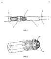
- FIG. 1 shows a second release assembly in accordance with an embodiment of the present invention.
- the second release assembly includes, sequentially from a proximal end P to a distal end D, a proximal fixing part 1, a guide part 2, a restrain part 3, a coupler 4 and a control guidewire 5.
- Fig. 1 also shows an inner tube 6 of the delivery system which extends through each of these components of the second release assembly.
- Fig. 2 is a diagram showing the proximal fixing part 1.
- the proximal fixing part 1 has an aperture 1a for the inner tube 6 to pass through, as well as a number of circumferentially distributed blind holes 1b.
- the number of the blind holes corresponds to the number of rods 3 a of the restrain part 3 so that the rods 3 a of the restrain part 3 can extend through the respective blind holes 1b.
- the proximal fixing part 1 may be injection molded, machined or fabricated by another technique.
- Fig. 3 is a diagram showing the guide part 2.
- the guide part 2 has an aperture 2a for the inner tube 6 to pass through, as well as a number of circumferentially distributed guide holes 2b.
- the number of the guide holes corresponds to the number of rods 3a of the restrain part 3 so that the rods 3a of the restrain part 3 can extend through the respective guide holes 2b, thereby maintaining each of the rods 3a of the restrain part 3 in a desired orientation without intersecting or bending.
- This also facilitates alignment and insertion of the rods 3a of the restrain part 3 into the blind holes 1b of the proximal fixing part 1.
- the guide part 2 may be fabricated by injection molding, machining or another technique from a material which may be implemented as a polymer or a metal.
- the polymer herein may include, but not limited to, Pebax, Nylon, PC, PE, PP and ABS.
- Figs. 4-6 are diagrams showing the restrain part 3.
- the restrain part 3 includes a number of rods 3a which are circumferentially distributed and secured to a section 3b defining a bore for the inner tube 6 to pass through.
- the number of the rods depends on the number of through holes 7a ( Fig. 7 ) provided at a proximal end of a stent 7.
- the rods 3a and the section 3b may be fabricated by injection molding, machining or another technique.
- the rods 3a and the section 3b may otherwise be connected to each other by, for example, but not limited to, welding, bonding or heat melting.
- Adhesives that can be used to effect the bonding include, but not limited to, Loctite 3011, 3321, 3493, 3494, 3321 and 3751; Dymax 203a-cth-f, 204-cth-f, 1201-m-sc and 1128a-m; NuSil MED-2000P; and Dow Coming Silastic Medical Adhesive Silicone, Type A.
- the material for fabricating the restrain part 3 may be a metal or a polymer such as, but not limited to, Pebax, Nylon, PC, PE, PP and ABS.
- the rods 3a and the section 3b may be formed as a single part (e.g., the case of the rods 3a' integral with the section 3b' shown in Fig. 5 ).
- the rods 3a and the section 3b may be formed separately and then connected together (e.g. the case of the rods 3a" in fixed connection with the section 3b" shown in Fig. 6 ).
- the coupler 4 is configured to couple the restrain part 3 to the control guidewire 5 to ensure that pulling the control guidewire 5 will lead to movement of the restrain part 3 toward the distal end.
- the coupling of the restrain part 3 and the control guidewire 5 may be accomplished by, for example, but not limited to, welding, bonding, riveting or heat melting.
- Adhesives that can be used to accomplish the bonding include, but not limited to, Loctite 3011, 3321, 3493, 3494, 3321 and 3751; Dymax 203a-cth-f, 204-cth-f, 1201-m-sc and 1128a-m; NuSil MED-2000P; and Dow Coming Silastic Medical Adhesive Silicone, Type A.
- the coupler 4 may be integrally formed with the section 3b', as shown in Fig. 5 .
- the coupler 4 may be omitted, with the control guidewire 5 being directly coupled to the section 3b", as shown in Fig. 6 .
- the coupling may be accomplished by, for example, but not limited to, welding, bonding, riveting, or two additional holes in the section 3b" for two strands of the control guidewire 5 to extend therethrough.
- a distal end of the double-stranded control guidewire 5 may be wrapped with a heat-shrink tube.
- the rods 3a of the restrain part 3 that extend through the through holes 7a at the proximal end of the stent 7 of the delivery system and are inserted in the blind holes 1b of the proximal fixing part 1 restrain the proximal end of the stent 7.
- the control guidewire 5 may be pulled to cause the restrain part 3 to be separated from the proximal fixing part 1 and move toward the distal end.
- the proximal end of the stent 7 may expand.
- a method for deploying the aortic stent 7 using the inventive delivery system may include the following steps.
Abstract
Description
- This invention relates generally to the field of medical devices and, in particular, to an aortic stent delivery system used in interventional treatment of an aortic aneurysm (including an aortic dissection). The invention is also directed to a second release assembly of the delivery system.
- Aortic diseases such as aortic aneurysm and aortic dissection aneurysm are some of the deadliest and most intractable vascular surgical diseases. Traditionally, the treatment of such diseases relied on open surgery for artificial vessel replacement, which, however, led to significant trauma and high mortality.
- In recent years, for high-risk aortic dissection patients, a simple, minimally-invasive interventional surgical procedure has been developed using a covered stent for endovascular repair of aortic dissection. In the procedure, the covered stent is introduced from a minimally invasive incision made in the patient's femoral artery and deployed to the aortic defect using a delivery system for protection and repair of the defective vessel.
- Currently, delivery systems for use in minimally invasive intervention of aortas for the treatment of aortic aneurysm employ a simple covered stent deployment method involving retrieval of an outer sheath which allows the stent to expand by itself due to its elasticity. This method is, however, lack of accuracy in deployment control, because once the stent is improperly located, its self-expansion immediately after the retrieval of the outer sheath will necessitate the use of the highly traumatic open surgery with high fatality for removing the stent.
- Chinese Utility Model Patent No.
CN202699194U discloses a bifurcated abdominal aortic covered stent and a related delivery system. The bifurcated abdominal aortic covered stent includes a tubular lattice frame of a shape memory alloy and a cover covering the tubular lattice frame, in which at least two sleeve branches project from a leading portion of the tubular lattice frame. The delivery system includes a deployment assembly that is extendable within the tubular lattice frame and comprised of guide wires and flexible sleeves. Each flexible sleeve has a leading portion that can extend through the tubular lattice frame into a corresponding one of the sleeve branches in a shape-adapted manner, and each guide wire has one end arranged at a trailing end of a corresponding flexible sleeve and the other end disposed within the flexible sleeve and in connection with the corresponding sleeve branch. However, this delivery system is still not accurate enough in deployment control for the covered stent, and thus makes it necessary to rely on open surgery for removal of the covered stent when it is deployed at an undesired location. - The present invention addresses the inaccurate deployment control issue of the current delivery systems for use in minimally invasive intervention of aortas for the treatment of aortic aneurysm by presenting a delivery system which allows second release of a proximal end of the stent, i.e., the stent being incompletely deployed with its proximal end being still restrained even after the outer sheath has been retrieved. In such a conf gurration, fine adjustments can still be made in the location of the stent to make sure that the stent is accurately deployed.
- In one aspect, the present invention provides a second release assembly for use in a delivery system. The second release assembly is disposed at a proximal end of the delivery system and includes, sequentially from a proximal end to a distal end, a proximal fixing part, a restrain part and a control guidewire. A proximal end of the restrain part is detachably connected to the proximal fixing part, and a distal end of the restrain part is coupled to the control guidewire. With this design, the stent can be incompletely deployed, i.e., the main part of the stent having expanded with its proximal end still being restrained. In this configuration, fine adjustments are still possible in the position of the stent. As a result, the proximal end can be deployed, resulting in complete deployment of the stent, after the stent has been tuned to a desired position.
- According to the present invention, the restrain part may be a single part or a combination of several parts. The restrain part may be formed of a material which is a polymer or a metal.
- Preferably, the second release assembly further includes a guide part, the restrain part is configured to extend through the guide part and is thus directed and maintained at a predetermined orientation by the guide part. The guide part may also be formed of a material which is a polymer or a metal.
- Preferably, the second release assembly further includes a coupler for coupling the distal end of the restrain part to the control guidewire, a proximal end of the coupler is in fixed connection with the restrain part or is integrally formed with the restrain part, a distal end of the coupler is in fixed or detachable connection with the control guidewire. The coupler may also be formed of a material which is a polymer or a metal. The polymer may include, but not limited to, Pebax, Nylon, PC, PE, PP and ABS.
- According to an embodiment of the present invention, the restrain part includes a plurality of rods which are circumferentially distributed.
- According to an embodiment of the present invention, the restrain part further includes a section defining a bore allowing an inner tube of the delivery system to pass therethrough, and the section is connected to or integrally formed with the plurality of rods.
- According to an embodiment of the present invention, the proximal fixing part is provided with a plurality of blind holes which are circumferentially distributed and correspond to the plurality of rods, and each of the plurality of rods is inserted in a corresponding one of the plurality of blind holes.
- According to an embodiment of the present invention, the guide part is provided with a plurality of guide holes which are circumferentially distributed and correspond to the plurality of rods, and wherein each of the plurality of rods extends through a corresponding one of the plurality of guide holes. With this design, the guide part can direct each leg of the restrain part to a desired orientation and maintain it thereat without intersecting or bending. This also facilitates alignment and insertion of the rods of the restrain part into the respective blind holes of the proximal fixing part.
- In a second aspect, the present invention provides a stent delivery system including an outer sheath, an inner tube and a stent. The delivery system further includes a second release assembly as defined above to control the deployment of a proximal end of the stent. The second release assembly extends longitudinally within the outer sheath and receives the inner tube. The stent is provided with through holes at the proximal end, and the restrain part of the second release assembly extends through the through holes, thereby restraining the proximal end of the stent. With this design, the second release assembly can work together with the stent that is provided with the through holes at the proximal end, to restrain the proximal end of the stent by the second release assembly. As such, after the outer sheath has been retrieved, the stent will expand in the most part, with its proximal end still being restrained to an unexpanded configuration. At this time, the stent may be finely adjusted in its position such that it is accurately positioned at a desired site. After it is confirmed that the stent has been accurately located, the second release assembly may be controlled to deploy the proximal end of the stent, thereby resulting in complete expansion thereof.
- Preferably, the delivery system further includes a conical tip disposed at a proximal end of the delivery system and is coupled to the proximal end of the proximal fixing part.
- According to the present invention, the delivery system and the second release assembly enable delayed and, hence, more accurate deployment of the stent.
- The features and advantages of the present invention will become readily apparent from the following detailed description of a few embodiments thereof, which is to be read in connection with the accompanying drawings. It is apparent that the embodiments set forth below are only a part, but not all, of the possible embodiments of the present invention. In light of the teachings of the embodiments disclosed herein, those skilled in the art can make all other possible embodiments without exerting creative efforts. All such embodiments are also embraced in the scope of this invention. In the drawings:
-
Fig. 1 is a schematic perspective view of a second release assembly in accordance with an embodiment of the present invention; -
Fig. 2 is a schematic perspective view of a proximal fixing part of a second release assembly in accordance with an embodiment of the present invention; -
Fig. 3 is a schematic perspective view of a guide part of a second release assembly in accordance with an embodiment of the present invention; -
Fig. 4 is a schematic perspective view of a restrain part of a second release assembly in accordance with an embodiment of the present invention; -
Fig. 5 is a schematic perspective view of a restrain part of a second release assembly in accordance with another embodiment of the present invention; -
Fig. 6 is a schematic perspective view of a restrain part of a second release assembly in accordance with yet another embodiment of the present invention; -
Fig. 7 is a schematic illustrating a proximal end of a stent according to the present invention; and -
Figs. 8 to 10 schematically illustrate a process of deploying a stent from a delivery system in accordance with an embodiment of the present invention. - Embodiments of the inventive aortic stent delivery system will be described below with reference to the accompanying drawings. In the following description, for the sake of convenience, the terms "distal", "proximal" and "longitudinal" are used, in which "distal" and "proximal" refer to positions located close to and far away from a manipulated end of the delivery system, respectively, and "longitudinal" refers to a direction in which the delivery system extends.
-
FIG. 1 shows a second release assembly in accordance with an embodiment of the present invention. As shown inFig. 1 , the second release assembly includes, sequentially from a proximal end P to a distal end D, a proximal fixingpart 1, a guide part 2, a restrainpart 3, acoupler 4 and acontrol guidewire 5.Fig. 1 also shows an inner tube 6 of the delivery system which extends through each of these components of the second release assembly. -
Fig. 2 is a diagram showing the proximal fixingpart 1. As shown inFig. 2 , the proximal fixingpart 1 has an aperture 1a for the inner tube 6 to pass through, as well as a number of circumferentially distributed blind holes 1b. The number of the blind holes corresponds to the number ofrods 3 a of the restrainpart 3 so that therods 3 a of the restrainpart 3 can extend through the respective blind holes 1b. Theproximal fixing part 1 may be injection molded, machined or fabricated by another technique. -
Fig. 3 is a diagram showing the guide part 2. As shown inFig. 3 , the guide part 2 has an aperture 2a for the inner tube 6 to pass through, as well as a number of circumferentially distributed guide holes 2b. The number of the guide holes corresponds to the number ofrods 3a of the restrainpart 3 so that therods 3a of the restrainpart 3 can extend through the respective guide holes 2b, thereby maintaining each of therods 3a of the restrainpart 3 in a desired orientation without intersecting or bending. This also facilitates alignment and insertion of therods 3a of the restrainpart 3 into the blind holes 1b of the proximal fixingpart 1. The guide part 2 may be fabricated by injection molding, machining or another technique from a material which may be implemented as a polymer or a metal. The polymer herein may include, but not limited to, Pebax, Nylon, PC, PE, PP and ABS. -
Figs. 4-6 are diagrams showing the restrainpart 3. As shown inFig. 4 , the restrainpart 3 includes a number ofrods 3a which are circumferentially distributed and secured to asection 3b defining a bore for the inner tube 6 to pass through. The number of the rods depends on the number of through holes 7a (Fig. 7 ) provided at a proximal end of astent 7. Therods 3a and thesection 3b may be fabricated by injection molding, machining or another technique. Therods 3a and thesection 3b may otherwise be connected to each other by, for example, but not limited to, welding, bonding or heat melting. Adhesives that can be used to effect the bonding include, but not limited to, Loctite 3011, 3321, 3493, 3494, 3321 and 3751; Dymax 203a-cth-f, 204-cth-f, 1201-m-sc and 1128a-m; NuSil MED-2000P; and Dow Coming Silastic Medical Adhesive Silicone, Type A. The material for fabricating the restrainpart 3 may be a metal or a polymer such as, but not limited to, Pebax, Nylon, PC, PE, PP and ABS. - Of the restrain
part 3, therods 3a and thesection 3b may be formed as a single part (e.g., the case of therods 3a' integral with thesection 3b' shown inFig. 5 ). Alternatively, therods 3a and thesection 3b may be formed separately and then connected together (e.g. the case of therods 3a" in fixed connection with thesection 3b" shown inFig. 6 ). - The
coupler 4 is configured to couple the restrainpart 3 to the control guidewire 5 to ensure that pulling thecontrol guidewire 5 will lead to movement of the restrainpart 3 toward the distal end. The coupling of the restrainpart 3 and thecontrol guidewire 5 may be accomplished by, for example, but not limited to, welding, bonding, riveting or heat melting. Adhesives that can be used to accomplish the bonding include, but not limited to, Loctite 3011, 3321, 3493, 3494, 3321 and 3751; Dymax 203a-cth-f, 204-cth-f, 1201-m-sc and 1128a-m; NuSil MED-2000P; and Dow Coming Silastic Medical Adhesive Silicone, Type A. - The
coupler 4 may be integrally formed with thesection 3b', as shown inFig. 5 . Alternatively, thecoupler 4 may be omitted, with the control guidewire 5 being directly coupled to thesection 3b", as shown inFig. 6 . The coupling may be accomplished by, for example, but not limited to, welding, bonding, riveting, or two additional holes in thesection 3b" for two strands of the control guidewire 5 to extend therethrough. For ease of operation, a distal end of the double-strandedcontrol guidewire 5 may be wrapped with a heat-shrink tube. - In the second release assembly, the
rods 3a of the restrainpart 3 that extend through the through holes 7a at the proximal end of thestent 7 of the delivery system and are inserted in the blind holes 1b of the proximal fixingpart 1 restrain the proximal end of thestent 7. When to deploy the proximal end of the stent, thecontrol guidewire 5 may be pulled to cause the restrainpart 3 to be separated from the proximal fixingpart 1 and move toward the distal end. Upon therods 3a of the restrainpart 3 leaving the through holes 7a of thestent 7, the proximal end of thestent 7 may expand. - A method for deploying the
aortic stent 7 using the inventive delivery system may include the following steps. - In
step 1, thestent 7 is loaded. The restrainpart 3 is brought to move such that its rods are inserted through the guide holes 2b of the guide part 2. The proximal end of thestent 7 is crimped, and the restrainpart 3 is further moved such that therods 3 a pass through the through holes 7a at the proximal end of thestent 7 and extend into the blind holes 1b of theproximal fxing part 1. As such, the proximal end of thestent 7 is restrained by therods 3a and thus cannot expand. - In step 2, the delivery system is introduced. As shown in
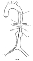
Fig. 8 , a guide wire 8 is first deployed in a path from a femoral artery to the abdominal aorta, and the delivery system incorporating the second release assembly on which thestent 7 is loaded is then percutaneously introduced and advanced over the guide wire 8 to the abdominal aorta. In the delivery system, the second release assembly extends longitudinally within anouter sheath 10, with the inner tube 6 extending through each of the above-described components of the second release assembly. In addition, the proximal fixingpart 1 of the second release assembly is coupled to a conical tip 9. - In
step 3, the delivery system is further advanced over the guide wire 8 to the site of an aortic aneurysm, with a radiopaque marker (not shown) being situated at a neck portion of the aneurysm, as shown inFig. 8 . - In
step 4, theouter sheath 10 is retrieved. Specifically, after being properly located, theouter sheath 10 is retrieved to allow expansion of the trunk and branches of thestent 7 except the proximal end of thestent 7 which is still restrained by the second release assembly (Fig. 9 ). - In
step 5, the proximal end is deployed. Fine adjustments of the stent location are made if needed to make sure that the stent is located correctly. Thereafter, thecontrol guidewire 5 is pulled to cause the restrainpart 3 to move longitudinally toward the distal end. As a result, therods 3a of the restrainpart 3 are disengaged from the proximal fixingpart 1 and then disengaged from the through holes 7a formed at the proximal end of thestent 7, thereby allowing expansion of the proximal end, i.e., complete deployment of the stent 7 (Fig. 10 ). - Finally, the delivery system and guide wire 8 are also retrieved, which lead to completion of the deployment of the
stent 7. - The forgoing description of the embodiments disclosed herein enables those skilled in the art to implement or use the present invention. Various modifications of these embodiments are obvious to those of ordinary skill in the art. The general principles as defined herein are applicable to other embodiments without departing from the spirit or scope of the present invention. Thus, the present invention is not limited to the disclosed embodiments, but rather it covers all those within the broadest scope consistent with the principles as defined herein.
Claims (9)
- A second release assembly for use in a delivery system, the second release assembly being disposed at a proximal end of the delivery system, wherein the second release assembly comprises, sequentially from a proximal end to a distal end, a proximal fixing part, a restrain part and a control guidewire, a proximal end of the restrain part being detachably connected to the proximal fixing part, a distal end of the restrain part coupled to the control guidewire.
- The second release assembly according to claim 1, further comprising a guide part, the restrain part configured to extend through the guide part and is thus directed and maintained at a predetermined orientation by the guide part.
- The second release assembly according to claim 1, further comprising a coupler for coupling the distal end of the restrain part to the control guidewire, a proximal end of the coupler being in fixed connection with the restrain part or being integrally formed with the restrain part, a distal end of the coupler being in fixed or detachable connection with the control guidewire.
- The second release assembly according to claim 1 or 2, wherein the restrain part comprises a plurality of rods which are circumferentially distributed.
- The second release assembly according to claim 4, wherein the restrain part further comprises a section defining a bore allowing an inner tube of the delivery system to pass therethrough, the section being connected to or integrally formed with the plurality of rods.
- The second release assembly according to claim 4, wherein the proximal fixing part is provided with a plurality of blind holes which are circumferentially distributed and correspond to the plurality of rods, and wherein each of the plurality of rods is inserted in a corresponding one of the plurality of blind holes.
- The second release assembly according to claim 4, wherein the guide part is provided with a plurality of guide holes which are circumferentially distributed and correspond to the plurality of rods, and wherein each of the plurality of rods extends through a corresponding one of the plurality of guide holes.
- A stent delivery system comprising an outer sheath, an inner tube and a stent, wherein the delivery system further comprises a second release assembly as defined in any one of claims 1 to 7, the second release assembly being configured to control deployment of a proximal end of the stent, the second release assembly extending longitudinally within the outer sheath and receiving the inner tube, and wherein the stent is provided with through holes at the proximal end, and the restrain part of the second release assembly extends through the through holes, thereby restraining the proximal end of the stent.
- The delivery system according to claim 8, wherein the delivery system further comprises a conical tip disposed at a proximal end of the delivery system and coupled to the proximal end of the proximal fixing part.
Priority Applications (1)
| Application Number | Priority Date | Filing Date | Title |
|---|---|---|---|
| PL14872805T PL3085340T3 (en) | 2013-12-17 | 2014-12-16 | Stent delivery system and post release assembly thereof |
Applications Claiming Priority (2)
| Application Number | Priority Date | Filing Date | Title |
|---|---|---|---|
| CN201310693077.7A CN104706449B (en) | 2013-12-17 | 2013-12-17 | A kind of stent delivery system and component is discharged thereafter |
| PCT/CN2014/093973 WO2015090188A1 (en) | 2013-12-17 | 2014-12-16 | Stent delivery system and post release assembly thereof |
Publications (3)
| Publication Number | Publication Date |
|---|---|
| EP3085340A1 true EP3085340A1 (en) | 2016-10-26 |
| EP3085340A4 EP3085340A4 (en) | 2017-05-31 |
| EP3085340B1 EP3085340B1 (en) | 2021-04-14 |
Family
ID=53402104
Family Applications (1)
| Application Number | Title | Priority Date | Filing Date |
|---|---|---|---|
| EP14872805.8A Active EP3085340B1 (en) | 2013-12-17 | 2014-12-16 | Stent delivery system and post release assembly thereof |
Country Status (7)
| Country | Link |
|---|---|
| EP (1) | EP3085340B1 (en) |
| CN (1) | CN104706449B (en) |
| BR (1) | BR112016013956B1 (en) |
| ES (1) | ES2873477T3 (en) |
| PL (1) | PL3085340T3 (en) |
| PT (1) | PT3085340T (en) |
| WO (1) | WO2015090188A1 (en) |
Cited By (3)
| Publication number | Priority date | Publication date | Assignee | Title |
|---|---|---|---|---|
| WO2019136294A1 (en) * | 2018-01-07 | 2019-07-11 | Suzhou Jiecheng Medical Technology Co., Ltd. | Prosthetic heart valve delivery system |
| US11259923B2 (en) | 2013-03-14 | 2022-03-01 | Jc Medical, Inc. | Methods and devices for delivery of a prosthetic valve |
| US11406497B2 (en) | 2013-03-14 | 2022-08-09 | Jc Medical, Inc. | Heart valve prosthesis |
Families Citing this family (16)
| Publication number | Priority date | Publication date | Assignee | Title |
|---|---|---|---|---|
| CN105105870B (en) * | 2015-07-27 | 2023-12-01 | 上海微创医疗器械(集团)有限公司 | Heart valve conveying device |
| CN105943210A (en) * | 2015-12-23 | 2016-09-21 | 微创心脉医疗科技(上海)有限公司 | Intervention apparatus sheath tube and manufacturing method thereof |
| CN105943211A (en) * | 2015-12-23 | 2016-09-21 | 微创心脉医疗科技(上海)有限公司 | Stent delivering system and back releasing assembly thereof |
| ES2919233T3 (en) * | 2015-12-23 | 2022-07-22 | Shanghai Microport Endovascular Medtech Group Co Ltd | Stent delivery system and its assemblies |
| CN105943213B (en) * | 2015-12-23 | 2019-01-04 | 微创心脉医疗科技(上海)有限公司 | Stent delivery system and its application method |
| CN106580530B (en) * | 2016-12-20 | 2018-11-16 | 有研医疗器械(北京)有限公司 | One kind discharging membrane-covered support conveying system and method behind pinpoint remote, proximal end |
| CN109199660B (en) * | 2017-06-29 | 2020-12-01 | 先健科技(深圳)有限公司 | Medical conveying device and conveying system thereof |
| CN109567981A (en) * | 2017-09-29 | 2019-04-05 | 微创心脉医疗科技(上海)有限公司 | Support system and its conveying device, rear release structure and bracket |
| CN109984877A (en) * | 2017-12-28 | 2019-07-09 | 先健科技(深圳)有限公司 | Intraluminal stent system |
| CN109771112A (en) * | 2018-12-07 | 2019-05-21 | 先健科技(深圳)有限公司 | The connector of transportation system |
| CN114650795A (en) * | 2019-10-31 | 2022-06-21 | 杭州启明医疗器械股份有限公司 | Interventional instrument release control mechanism, release method and interventional instrument delivery system |
| CN111035486B (en) * | 2019-12-25 | 2024-01-23 | 上海微创心脉医疗科技(集团)股份有限公司 | Stent delivery system and method of loading stents |
| CN113925651A (en) * | 2020-06-30 | 2022-01-14 | 上海微创心脉医疗科技(集团)股份有限公司 | Positioning device and conveying device comprising same |
| CN116098740A (en) * | 2021-06-24 | 2023-05-12 | 杭州启明医疗器械股份有限公司 | Fully recovered prosthetic heart valve system |
| CN116262078A (en) * | 2021-12-14 | 2023-06-16 | 上海拓脉医疗科技有限公司 | Support conveying device and support conveying system |
| CN114098883B (en) * | 2022-01-27 | 2022-06-17 | 上海微创心脉医疗科技(集团)股份有限公司 | Support conveying device and support conveying system |
Family Cites Families (16)
| Publication number | Priority date | Publication date | Assignee | Title |
|---|---|---|---|---|
| US7264632B2 (en) * | 2002-06-07 | 2007-09-04 | Medtronic Vascular, Inc. | Controlled deployment delivery system |
| US8292943B2 (en) * | 2003-09-03 | 2012-10-23 | Bolton Medical, Inc. | Stent graft with longitudinal support member |
| CA2573889C (en) * | 2004-06-16 | 2014-02-04 | Cook Incorporated | Thoracic deployment device and stent graft |
| US8118852B2 (en) * | 2005-07-13 | 2012-02-21 | Cook Medical Technologies Llc | Introducer for self-expandable medical device |
| DE102006053748B3 (en) * | 2006-11-09 | 2008-04-10 | Jotec Gmbh | Insert system for inserting and releasing e.g. endovascular stent, has fixing system with cover unit including pivoting units axially extending in proximal direction of insert system, and retaining unit arranged proximal to cover unit |
| CN107961098A (en) * | 2008-06-30 | 2018-04-27 | 波顿医疗公司 | System and method for abdominal aneurvsm |
| US8876877B2 (en) * | 2009-04-23 | 2014-11-04 | Medtronic Vascular, Inc. | Centering for a TAA |
| CN201445575U (en) * | 2009-04-29 | 2010-05-05 | 天健医疗科技(苏州)有限公司 | Artery tectorial membrane support and conveyer thereof |
| US8771333B2 (en) * | 2009-06-23 | 2014-07-08 | Cordis Corporation | Stent-graft securement device |
| US8764811B2 (en) * | 2010-04-20 | 2014-07-01 | Medtronic Vascular, Inc. | Controlled tip release stent graft delivery system and method |
| PL3231401T3 (en) * | 2010-06-24 | 2020-09-21 | CARDINAL HEALTH SWITZERLAND 515 GmbH | Apparatus for pulling a tensile member from a medical device |
| CN102038565B (en) * | 2010-12-17 | 2013-08-14 | 北京有色金属研究总院 | Great vascular stent delivery system |
| GB2500881A (en) * | 2012-03-30 | 2013-10-09 | Cook Medical Technologies Llc | Stent holding structure for introducers |
| CN202699194U (en) | 2012-05-16 | 2013-01-30 | 王志伟 | Branch-type abdominal aorta covered stent and conveying system thereof |
| CN103230310B (en) * | 2013-04-19 | 2015-07-15 | 湖南埃普特医疗器械有限公司 | Thoracic aortic aneurysm coated stent and thoracic aortic aneurysm minimally invasive treatment system |
| CN203619729U (en) * | 2013-12-17 | 2014-06-04 | 微创心脉医疗科技(上海)有限公司 | Stent conveying system and rear release component thereof |
-
2013
- 2013-12-17 CN CN201310693077.7A patent/CN104706449B/en active Active
-
2014
- 2014-12-16 PT PT148728058T patent/PT3085340T/en unknown
- 2014-12-16 ES ES14872805T patent/ES2873477T3/en active Active
- 2014-12-16 PL PL14872805T patent/PL3085340T3/en unknown
- 2014-12-16 EP EP14872805.8A patent/EP3085340B1/en active Active
- 2014-12-16 WO PCT/CN2014/093973 patent/WO2015090188A1/en active Application Filing
- 2014-12-16 BR BR112016013956-9A patent/BR112016013956B1/en active IP Right Grant
Cited By (7)
| Publication number | Priority date | Publication date | Assignee | Title |
|---|---|---|---|---|
| US11259923B2 (en) | 2013-03-14 | 2022-03-01 | Jc Medical, Inc. | Methods and devices for delivery of a prosthetic valve |
| US11406497B2 (en) | 2013-03-14 | 2022-08-09 | Jc Medical, Inc. | Heart valve prosthesis |
| WO2019136294A1 (en) * | 2018-01-07 | 2019-07-11 | Suzhou Jiecheng Medical Technology Co., Ltd. | Prosthetic heart valve delivery system |
| JP2021510105A (en) * | 2018-01-07 | 2021-04-15 | ジェイシー メディカル、インコーポレイテッド | Artificial heart valve delivery system |
| US11020226B2 (en) | 2018-01-07 | 2021-06-01 | Jc Medical, Inc. | Prosthetic heart valve delivery system |
| JP6990315B2 (en) | 2018-01-07 | 2022-01-12 | ジェイシー メディカル、インコーポレイテッド | Artificial heart valve delivery system |
| US11331184B2 (en) | 2018-01-07 | 2022-05-17 | Jc Medical, Inc. | Methods and devices for delivery of a prosthetic valve |
Also Published As
| Publication number | Publication date |
|---|---|
| EP3085340B1 (en) | 2021-04-14 |
| CN104706449A (en) | 2015-06-17 |
| CN104706449B (en) | 2017-11-07 |
| BR112016013956B1 (en) | 2022-01-11 |
| WO2015090188A1 (en) | 2015-06-25 |
| BR112016013956A2 (en) | 2017-08-08 |
| PT3085340T (en) | 2021-05-10 |
| PL3085340T3 (en) | 2021-11-15 |
| ES2873477T3 (en) | 2021-11-03 |
| EP3085340A4 (en) | 2017-05-31 |
Similar Documents
| Publication | Publication Date | Title |
|---|---|---|
| EP3085340A1 (en) | Stent delivery system and post release assembly thereof | |
| EP1691719B1 (en) | Introducer for an iliac side branch device | |
| EP2282704B1 (en) | Introducer | |
| EP3260089B1 (en) | Apparatus for delivering a braided stent with expansion rings | |
| US8663306B2 (en) | Introducer with extension | |
| EP1517652B1 (en) | Thoracic introducer | |
| EP1924220B1 (en) | Endoluminal prosthesis adapted to deployment in a distorted branched body lumen | |
| EP2777606B1 (en) | Extension for iliac branch delivery device and methods of using the same | |
| EP2535025A1 (en) | Trigger wire release mechanism | |
| EP2792336A1 (en) | Delivery system comprising a pre-loaded iliac branch device | |
| US11090159B2 (en) | Heart implant | |
| JP2016185362A (en) | Apparatus for deploying a stent graft | |
| CN203619729U (en) | Stent conveying system and rear release component thereof | |
| US11564788B1 (en) | Single site access aortic aneurysm repair method | |
| US11504222B1 (en) | Branched graft assembly method in vivo | |
| US11141297B2 (en) | Endovascular delivery device having an improved top-cap assembly | |
| US20150173925A1 (en) | Delivery device with an extension sheath and methods of using the same | |
| US20190231569A1 (en) | Drivers and set for the insertion of connectable implants | |
| EP3539506A1 (en) | Preloaded pusher tip for endografts | |
| EP3064177B1 (en) | Delivery device with an extension sheath |
Legal Events
| Date | Code | Title | Description |
|---|---|---|---|
| PUAI | Public reference made under article 153(3) epc to a published international application that has entered the european phase |
Free format text: ORIGINAL CODE: 0009012 |
|
| 17P | Request for examination filed |
Effective date: 20160708 |
|
| AK | Designated contracting states |
Kind code of ref document: A1 Designated state(s): AL AT BE BG CH CY CZ DE DK EE ES FI FR GB GR HR HU IE IS IT LI LT LU LV MC MK MT NL NO PL PT RO RS SE SI SK SM TR |
|
| AX | Request for extension of the european patent |
Extension state: BA ME |
|
| DAX | Request for extension of the european patent (deleted) | ||
| A4 | Supplementary search report drawn up and despatched |
Effective date: 20170502 |
|
| RIC1 | Information provided on ipc code assigned before grant |
Ipc: A61F 2/962 20130101ALI20170424BHEP Ipc: A61F 2/954 20130101ALI20170424BHEP Ipc: A61F 2/95 20130101ALI20170424BHEP Ipc: A61F 2/966 20130101AFI20170424BHEP |
|
| RAP1 | Party data changed (applicant data changed or rights of an application transferred) |
Owner name: SHANGHAI MICROPORT ENDOVASCULAR CO., LTD. |
|
| RAP1 | Party data changed (applicant data changed or rights of an application transferred) |
Owner name: SHANGHAI MICROPORT ENDOVASCULAR MEDTECH CO., LTD. |
|
| STAA | Information on the status of an ep patent application or granted ep patent |
Free format text: STATUS: EXAMINATION IS IN PROGRESS |
|
| 17Q | First examination report despatched |
Effective date: 20200224 |
|
| GRAP | Despatch of communication of intention to grant a patent |
Free format text: ORIGINAL CODE: EPIDOSNIGR1 |
|
| STAA | Information on the status of an ep patent application or granted ep patent |
Free format text: STATUS: GRANT OF PATENT IS INTENDED |
|
| INTG | Intention to grant announced |
Effective date: 20201120 |
|
| GRAS | Grant fee paid |
Free format text: ORIGINAL CODE: EPIDOSNIGR3 |
|
| GRAA | (expected) grant |
Free format text: ORIGINAL CODE: 0009210 |
|
| STAA | Information on the status of an ep patent application or granted ep patent |
Free format text: STATUS: THE PATENT HAS BEEN GRANTED |
|
| AK | Designated contracting states |
Kind code of ref document: B1 Designated state(s): AL AT BE BG CH CY CZ DE DK EE ES FI FR GB GR HR HU IE IS IT LI LT LU LV MC MK MT NL NO PL PT RO RS SE SI SK SM TR |
|
| RAP3 | Party data changed (applicant data changed or rights of an application transferred) |
Owner name: SHANGHAI MICROPORT ENDOVASCULAR MEDTECH (GROUP) CO., LTD. |
|
| REG | Reference to a national code |
Ref country code: GB Ref legal event code: FG4D |
|
| REG | Reference to a national code |
Ref country code: CH Ref legal event code: EP |
|
| REG | Reference to a national code |
Ref country code: DE Ref legal event code: R096 Ref document number: 602014076666 Country of ref document: DE |
|
| REG | Reference to a national code |
Ref country code: CH Ref legal event code: NV Representative=s name: DENNEMEYER AG, CH |
|
| REG | Reference to a national code |
Ref country code: PT Ref legal event code: SC4A Ref document number: 3085340 Country of ref document: PT Date of ref document: 20210510 Kind code of ref document: T Free format text: AVAILABILITY OF NATIONAL TRANSLATION Effective date: 20210504 |
|
| REG | Reference to a national code |
Ref country code: IE Ref legal event code: FG4D |
|
| REG | Reference to a national code |
Ref country code: AT Ref legal event code: REF Ref document number: 1381626 Country of ref document: AT Kind code of ref document: T Effective date: 20210515 |
|
| REG | Reference to a national code |
Ref country code: GR Ref legal event code: EP Ref document number: 20210401385 Country of ref document: GR Effective date: 20210709 |
|
| REG | Reference to a national code |
Ref country code: LT Ref legal event code: MG9D |
|
| REG | Reference to a national code |
Ref country code: AT Ref legal event code: MK05 Ref document number: 1381626 Country of ref document: AT Kind code of ref document: T Effective date: 20210414 |
|
| REG | Reference to a national code |
Ref country code: NL Ref legal event code: MP Effective date: 20210414 |
|
| PG25 | Lapsed in a contracting state [announced via postgrant information from national office to epo] |
Ref country code: HR Free format text: LAPSE BECAUSE OF FAILURE TO SUBMIT A TRANSLATION OF THE DESCRIPTION OR TO PAY THE FEE WITHIN THE PRESCRIBED TIME-LIMIT Effective date: 20210414 Ref country code: FI Free format text: LAPSE BECAUSE OF FAILURE TO SUBMIT A TRANSLATION OF THE DESCRIPTION OR TO PAY THE FEE WITHIN THE PRESCRIBED TIME-LIMIT Effective date: 20210414 Ref country code: LT Free format text: LAPSE BECAUSE OF FAILURE TO SUBMIT A TRANSLATION OF THE DESCRIPTION OR TO PAY THE FEE WITHIN THE PRESCRIBED TIME-LIMIT Effective date: 20210414 Ref country code: NL Free format text: LAPSE BECAUSE OF FAILURE TO SUBMIT A TRANSLATION OF THE DESCRIPTION OR TO PAY THE FEE WITHIN THE PRESCRIBED TIME-LIMIT Effective date: 20210414 Ref country code: BG Free format text: LAPSE BECAUSE OF FAILURE TO SUBMIT A TRANSLATION OF THE DESCRIPTION OR TO PAY THE FEE WITHIN THE PRESCRIBED TIME-LIMIT Effective date: 20210714 Ref country code: AT Free format text: LAPSE BECAUSE OF FAILURE TO SUBMIT A TRANSLATION OF THE DESCRIPTION OR TO PAY THE FEE WITHIN THE PRESCRIBED TIME-LIMIT Effective date: 20210414 |
|
| REG | Reference to a national code |
Ref country code: ES Ref legal event code: FG2A Ref document number: 2873477 Country of ref document: ES Kind code of ref document: T3 Effective date: 20211103 |
|
| PG25 | Lapsed in a contracting state [announced via postgrant information from national office to epo] |
Ref country code: IS Free format text: LAPSE BECAUSE OF FAILURE TO SUBMIT A TRANSLATION OF THE DESCRIPTION OR TO PAY THE FEE WITHIN THE PRESCRIBED TIME-LIMIT Effective date: 20210814 Ref country code: LV Free format text: LAPSE BECAUSE OF FAILURE TO SUBMIT A TRANSLATION OF THE DESCRIPTION OR TO PAY THE FEE WITHIN THE PRESCRIBED TIME-LIMIT Effective date: 20210414 Ref country code: NO Free format text: LAPSE BECAUSE OF FAILURE TO SUBMIT A TRANSLATION OF THE DESCRIPTION OR TO PAY THE FEE WITHIN THE PRESCRIBED TIME-LIMIT Effective date: 20210714 Ref country code: RS Free format text: LAPSE BECAUSE OF FAILURE TO SUBMIT A TRANSLATION OF THE DESCRIPTION OR TO PAY THE FEE WITHIN THE PRESCRIBED TIME-LIMIT Effective date: 20210414 Ref country code: SE Free format text: LAPSE BECAUSE OF FAILURE TO SUBMIT A TRANSLATION OF THE DESCRIPTION OR TO PAY THE FEE WITHIN THE PRESCRIBED TIME-LIMIT Effective date: 20210414 |
|
| REG | Reference to a national code |
Ref country code: DE Ref legal event code: R097 Ref document number: 602014076666 Country of ref document: DE |
|
| PG25 | Lapsed in a contracting state [announced via postgrant information from national office to epo] |
Ref country code: RO Free format text: LAPSE BECAUSE OF FAILURE TO SUBMIT A TRANSLATION OF THE DESCRIPTION OR TO PAY THE FEE WITHIN THE PRESCRIBED TIME-LIMIT Effective date: 20210414 Ref country code: SK Free format text: LAPSE BECAUSE OF FAILURE TO SUBMIT A TRANSLATION OF THE DESCRIPTION OR TO PAY THE FEE WITHIN THE PRESCRIBED TIME-LIMIT Effective date: 20210414 Ref country code: SM Free format text: LAPSE BECAUSE OF FAILURE TO SUBMIT A TRANSLATION OF THE DESCRIPTION OR TO PAY THE FEE WITHIN THE PRESCRIBED TIME-LIMIT Effective date: 20210414 Ref country code: DK Free format text: LAPSE BECAUSE OF FAILURE TO SUBMIT A TRANSLATION OF THE DESCRIPTION OR TO PAY THE FEE WITHIN THE PRESCRIBED TIME-LIMIT Effective date: 20210414 Ref country code: EE Free format text: LAPSE BECAUSE OF FAILURE TO SUBMIT A TRANSLATION OF THE DESCRIPTION OR TO PAY THE FEE WITHIN THE PRESCRIBED TIME-LIMIT Effective date: 20210414 Ref country code: CZ Free format text: LAPSE BECAUSE OF FAILURE TO SUBMIT A TRANSLATION OF THE DESCRIPTION OR TO PAY THE FEE WITHIN THE PRESCRIBED TIME-LIMIT Effective date: 20210414 |
|
| PLBE | No opposition filed within time limit |
Free format text: ORIGINAL CODE: 0009261 |
|
| STAA | Information on the status of an ep patent application or granted ep patent |
Free format text: STATUS: NO OPPOSITION FILED WITHIN TIME LIMIT |
|
| 26N | No opposition filed |
Effective date: 20220117 |
|
| PG25 | Lapsed in a contracting state [announced via postgrant information from national office to epo] |
Ref country code: IS Free format text: LAPSE BECAUSE OF FAILURE TO SUBMIT A TRANSLATION OF THE DESCRIPTION OR TO PAY THE FEE WITHIN THE PRESCRIBED TIME-LIMIT Effective date: 20210814 Ref country code: AL Free format text: LAPSE BECAUSE OF FAILURE TO SUBMIT A TRANSLATION OF THE DESCRIPTION OR TO PAY THE FEE WITHIN THE PRESCRIBED TIME-LIMIT Effective date: 20210414 |
|
| PG25 | Lapsed in a contracting state [announced via postgrant information from national office to epo] |
Ref country code: MC Free format text: LAPSE BECAUSE OF FAILURE TO SUBMIT A TRANSLATION OF THE DESCRIPTION OR TO PAY THE FEE WITHIN THE PRESCRIBED TIME-LIMIT Effective date: 20210414 |
|
| REG | Reference to a national code |
Ref country code: BE Ref legal event code: MM Effective date: 20211231 |
|
| PG25 | Lapsed in a contracting state [announced via postgrant information from national office to epo] |
Ref country code: LU Free format text: LAPSE BECAUSE OF NON-PAYMENT OF DUE FEES Effective date: 20211216 Ref country code: IE Free format text: LAPSE BECAUSE OF NON-PAYMENT OF DUE FEES Effective date: 20211216 |
|
| PG25 | Lapsed in a contracting state [announced via postgrant information from national office to epo] |
Ref country code: BE Free format text: LAPSE BECAUSE OF NON-PAYMENT OF DUE FEES Effective date: 20211231 |
|
| PGFP | Annual fee paid to national office [announced via postgrant information from national office to epo] |
Ref country code: PL Payment date: 20221212 Year of fee payment: 9 |
|
| PGFP | Annual fee paid to national office [announced via postgrant information from national office to epo] |
Ref country code: ES Payment date: 20230227 Year of fee payment: 9 Ref country code: CH Payment date: 20230103 Year of fee payment: 9 |
|
| PG25 | Lapsed in a contracting state [announced via postgrant information from national office to epo] |
Ref country code: HU Free format text: LAPSE BECAUSE OF FAILURE TO SUBMIT A TRANSLATION OF THE DESCRIPTION OR TO PAY THE FEE WITHIN THE PRESCRIBED TIME-LIMIT; INVALID AB INITIO Effective date: 20141216 |
|
| PG25 | Lapsed in a contracting state [announced via postgrant information from national office to epo] |
Ref country code: CY Free format text: LAPSE BECAUSE OF FAILURE TO SUBMIT A TRANSLATION OF THE DESCRIPTION OR TO PAY THE FEE WITHIN THE PRESCRIBED TIME-LIMIT Effective date: 20210414 |
|
| P01 | Opt-out of the competence of the unified patent court (upc) registered |
Effective date: 20231128 |
|
| PGFP | Annual fee paid to national office [announced via postgrant information from national office to epo] |
Ref country code: GR Payment date: 20231221 Year of fee payment: 10 Ref country code: GB Payment date: 20231220 Year of fee payment: 10 |
|
| PGFP | Annual fee paid to national office [announced via postgrant information from national office to epo] |
Ref country code: PT Payment date: 20231207 Year of fee payment: 10 Ref country code: IT Payment date: 20231228 Year of fee payment: 10 Ref country code: FR Payment date: 20231221 Year of fee payment: 10 Ref country code: DE Payment date: 20231214 Year of fee payment: 10 |
|
| PGFP | Annual fee paid to national office [announced via postgrant information from national office to epo] |
Ref country code: PL Payment date: 20231212 Year of fee payment: 10 |
|
| PGFP | Annual fee paid to national office [announced via postgrant information from national office to epo] |
Ref country code: ES Payment date: 20240129 Year of fee payment: 10 |