EP3085171B1 - Method and means for maintaining uplink time alignment - Google Patents
Method and means for maintaining uplink time alignment Download PDFInfo
- Publication number
- EP3085171B1 EP3085171B1 EP13826789.3A EP13826789A EP3085171B1 EP 3085171 B1 EP3085171 B1 EP 3085171B1 EP 13826789 A EP13826789 A EP 13826789A EP 3085171 B1 EP3085171 B1 EP 3085171B1
- Authority
- EP
- European Patent Office
- Prior art keywords
- reception point
- communication device
- transmit power
- network node
- reception
- Prior art date
- Legal status (The legal status is an assumption and is not a legal conclusion. Google has not performed a legal analysis and makes no representation as to the accuracy of the status listed.)
- Active
Links
- 238000000034 method Methods 0.000 title claims description 30
- 238000004891 communication Methods 0.000 claims description 121
- 238000005259 measurement Methods 0.000 claims description 41
- 230000011664 signaling Effects 0.000 claims description 39
- 230000005540 biological transmission Effects 0.000 claims description 15
- 238000004590 computer program Methods 0.000 claims description 15
- 230000033228 biological regulation Effects 0.000 description 10
- 230000006870 function Effects 0.000 description 8
- 230000008901 benefit Effects 0.000 description 6
- 230000009467 reduction Effects 0.000 description 4
- 230000003044 adaptive effect Effects 0.000 description 2
- 238000013459 approach Methods 0.000 description 2
- 230000008859 change Effects 0.000 description 2
- 238000005516 engineering process Methods 0.000 description 2
- 230000003287 optical effect Effects 0.000 description 2
- 230000000737 periodic effect Effects 0.000 description 2
- 230000002085 persistent effect Effects 0.000 description 2
- 239000007787 solid Substances 0.000 description 2
- 201000001718 Roberts syndrome Diseases 0.000 description 1
- 208000012474 Roberts-SC phocomelia syndrome Diseases 0.000 description 1
- 238000003491 array Methods 0.000 description 1
- 230000006399 behavior Effects 0.000 description 1
- 230000015556 catabolic process Effects 0.000 description 1
- 238000006731 degradation reaction Methods 0.000 description 1
- 230000008713 feedback mechanism Effects 0.000 description 1
- 230000007774 longterm Effects 0.000 description 1
- 230000007246 mechanism Effects 0.000 description 1
- 238000012545 processing Methods 0.000 description 1
- 238000005001 rutherford backscattering spectroscopy Methods 0.000 description 1
- 238000004088 simulation Methods 0.000 description 1
- 230000003595 spectral effect Effects 0.000 description 1
- 230000001360 synchronised effect Effects 0.000 description 1
Images

Classifications
-
- H—ELECTRICITY
- H04—ELECTRIC COMMUNICATION TECHNIQUE
- H04W—WIRELESS COMMUNICATION NETWORKS
- H04W52/00—Power management, e.g. TPC [Transmission Power Control], power saving or power classes
- H04W52/04—TPC
- H04W52/06—TPC algorithms
- H04W52/14—Separate analysis of uplink or downlink
- H04W52/146—Uplink power control
-
- H—ELECTRICITY
- H04—ELECTRIC COMMUNICATION TECHNIQUE
- H04W—WIRELESS COMMUNICATION NETWORKS
- H04W52/00—Power management, e.g. TPC [Transmission Power Control], power saving or power classes
- H04W52/04—TPC
- H04W52/30—TPC using constraints in the total amount of available transmission power
- H04W52/32—TPC of broadcast or control channels
- H04W52/325—Power control of control or pilot channels
-
- H—ELECTRICITY
- H04—ELECTRIC COMMUNICATION TECHNIQUE
- H04W—WIRELESS COMMUNICATION NETWORKS
- H04W52/00—Power management, e.g. TPC [Transmission Power Control], power saving or power classes
- H04W52/04—TPC
- H04W52/30—TPC using constraints in the total amount of available transmission power
- H04W52/36—TPC using constraints in the total amount of available transmission power with a discrete range or set of values, e.g. step size, ramping or offsets
- H04W52/367—Power values between minimum and maximum limits, e.g. dynamic range
-
- H—ELECTRICITY
- H04—ELECTRIC COMMUNICATION TECHNIQUE
- H04W—WIRELESS COMMUNICATION NETWORKS
- H04W52/00—Power management, e.g. TPC [Transmission Power Control], power saving or power classes
- H04W52/04—TPC
- H04W52/38—TPC being performed in particular situations
- H04W52/40—TPC being performed in particular situations during macro-diversity or soft handoff
-
- H—ELECTRICITY
- H04—ELECTRIC COMMUNICATION TECHNIQUE
- H04W—WIRELESS COMMUNICATION NETWORKS
- H04W52/00—Power management, e.g. TPC [Transmission Power Control], power saving or power classes
- H04W52/04—TPC
- H04W52/18—TPC being performed according to specific parameters
- H04W52/24—TPC being performed according to specific parameters using SIR [Signal to Interference Ratio] or other wireless path parameters
- H04W52/241—TPC being performed according to specific parameters using SIR [Signal to Interference Ratio] or other wireless path parameters taking into account channel quality metrics, e.g. SIR, SNR, CIR, Eb/lo
Definitions
- the technology disclosed herein relates generally to the field of wireless communication systems using coordinated multipoint, and in particular to timing measurements in such systems using uplink coordinated multipoint reception.
- a wireless communication system covers a geographical area which is divided into several radio coverage areas. Such radio coverage areas are often referred to as cells or sectors. Each radio coverage area is served by a radio base station (RBS), which may be denoted in different ways depending e.g. on radio access technology.
- RBS may be referred to as eNodeB or eNB for communication systems adapting to Long Term Evolution (LTE) standard.
- An access point (reception point/transmission point) refers to a set of co-located antennas that provide coverage to one radio coverage area.
- One RBS may serve one or several such radio coverage areas.
- Uplink Coordinated Multi-Point is a multi-antenna technique that commonly refers to utilizing received signals from more than one reception point, when performing reception for one communication device.
- the signals that are received by the various reception points can be combined and processed to obtain a final received signal, whereby also signals low in strength may be received with few errors. This can be compared to the presently more conventional case, where only one reception point, i.e. the serving reception point, is used when performing reception for one communication device.
- Uplink performance can be improved quite significantly by using UL CoMP, e.g. in heterogeneous (HetNet) network deployments.
- HetNet heterogeneous
- communication devices in a HetNet deployment that are served by macro RBS reception points but located quite close to a low power RBS reception point (e.g. a pico RBS reception point), can reduce their transmit power with a maintained service quality when using both the macro and pico reception points. Thereby the communication device radiates less interference towards the pico reception point.
- the signal quality in the serving reception point alone can fall below acceptable signal quality levels which are needed to perform uplink measurements such as measurements for uplink time alignment. These measurements are needed since e.g. control signaling on a physical uplink control channel (PUCCH) might only be received in the serving reception point.
- PUCCH physical uplink control channel
- the communication device does not receive a valid timing advance (TA) command during a configured time period, it will assume it is has lost uplink synchronization and will be forced to initiate a random access procedure prior to any physical uplink shared channel (PUSCH) or PUCCH transmission. Failure to measure uplink time alignment in the serving reception point would introduce this kind of unwanted behavior.
- TA timing advance
- the RBS has several alternatives of controlling the transmit power of communication devices.
- One way is to use a predefined signal reception quality in the reception point where the highest received signal quality is achieved, and base the transmit power thereon.
- the reception point having the highest received signal reception quality is not necessarily the serving reception point. This may in fact be a quite frequently occurring case, especially in heterogeneous network deployments with large differences in downlink output power, as illustrated in figure 1 .
- the communication system 1 comprises a macro RBS 2 and a pico RBS 3, and the macro RBS 2 is typically using higher transmit power than the pico RBS 3.
- An uplink signal from a communication device 4 may be received in the pico RBS 3 with a higher received signal reception quality (e.g.
- RSRP reference signal received power
- the transmit power control scheme of using a predefined signal reception quality has the benefit of ensuring that the communication device 4 does not cause high interference towards the low power pico RBS 3 while using the high power macro RBS 2 as the serving reception point, hence avoiding high interference from e.g. cell-edge macro communication devices towards the communication devices connected to the low power pico RBS 3.
- a drawback with using this transmit power control scheme together with UL CoMP is that the uplink signal quality in the serving reception point can become degraded to the point when e.g. uplink time alignment cannot be maintained towards the serving reception point.
- An objective of the present disclosure is to solve or at least alleviate at least the above mentioned problem.
- transmit power control of a communication device can be made towards the cell/ sector to which the communication has the best uplink signal quality. If having this type of transmit power control in a deployment using UL CoMP, then this may lead to the serving sector loosing uplink signal quality and necessary uplink measurements, e.g. for uplink time alignment, failing. Such situation may in particular arise in a HetNet deployment using UL CoMP reception, in which there maybe a large uplink/downlink unbalance as described earlier.
- the present disclosure provides, in various embodiments, a method to assure adequate timing measurements and to maintain uplink time alignment in a wireless communication system using uplink coordinated multipoint (UL CoMP) reception.
- UL CoMP uplink coordinated multipoint
- Various embodiments are thus disclosed for maintaining uplink time alignment while utilizing the benefits of UL CoMP together with uplink power control.
- a communication system 10 in which embodiments of the disclosure may be implemented, may be an LTE network.
- the communication system 10 comprises a number of network nodes 12, 13, e.g. radio base stations such as evolved Node Bs (eNBs), and also various other network entities such as network controllers, serving gateways (SGWs), mobility management entities (MMEs) etc.
- the eNB 12, 13 is configured to provide wireless communication for communication devices 14, 16.
- the communication device 14, 16 may be referred to as user equipment (UE), terminal, mobile station etc. and may for instance comprise a smart phone, a mobile phone or a laptop computer.
- Each network node 12, 13 may provide communication coverage for one or more geographical areas, denoted cells or sectors.
- the network node 12, 13, in the following referred to as RBS, is configured for uplink coordinated multipoint (UL CoMP) reception and may thus receive uplink signaling from one particular communication device 14 from several reception points. In figure 2 this is illustrated by arrows from the communication devices 14, 16 to two different reception points 35, 36.
- the reception points 35, 36 may be controlled by a single RBS 12, 13 or by different RBSs.
- the signaling sent from a particular communication device 14, 16 may thus be received by several reception points, and there is one serving RBS for this particular communication device 14, 16 (which of course may control all reception points with which the particular communication device communicates).
- the RBS serving a communication device 14, 16 is also configured to control the transmit power thereof.
- a reception point is typically chosen to be a serving reception point for a communication device based on downlink channel quality towards the communication device.
- the reception point towards which time alignment is to be maintained is typcially the serving reception point.
- the communication system 10 illustrated in figure 2 may then comprise a macro RBS 12 and a pico RBS 13, the macro RBS 12 being configured to use a higher transmit power than the pico RBS 13 and thus providing a larger coverage area than the pico RBS 13, which is configured to use a lower transmit power than the macro RBS 12 and reach users within a smaller coverage area.
- the transmit power of the communication devices 14, 16 is typically controlled by an open loop transmit power control and a closed loop transmit power control.
- an open loop power control the communication device 14, 16 receives a reference signal from the RBS 12, 13 sent with a fixed power value and information about this fixed power value.
- the communication device 14, 15 measures the power of the reference signal and may determine e.g. path loss to the RBS 12, 13 and may thereby determine with which transmit power to send.
- the open loop power control allows the communication device 14, 16 to select an appropriate transmit power so that the signal energy received at the serving reception point is considered good enough, i.e. such that a predefined signal reception quality is met.
- the closed loop power control provides the RBS 12, 13 with the possibility to give input to the communication device 14, 16 power control mechanism to for example compensate for estimation errors in the communication device 14, 16. This is realized by sending transmit power control (TPC) commands to the communication device 14, 16.
- TPC transmit power control
- the RBS 12, 13 measures power of signals received from the communication device 14, 16, and sends TPC commands to instruct the communication device 14, 16 to increase or decrease the transmit power accordingly.
- this latter feedback mechanism can also be used by the RBS 12, 13 to further influence the transmit power setting of the communication devices 14, 16, taking into account other considerations than the received signal energy at the serving reception point.
- considerations may be that more than one reception point is used to evaluate the appropriate transmit power of the communication devices 14, 16.
- FIG. 2 One example of such a power control scheme is depicted in figure 2 .
- communication devices 14, 16 illustrated in figure 2 are referred to as UE2 and UE1, respectively, and communication devices in general are referred to as UE.
- a first network node 12 is referred to as macro node 12, and a second network node 13 is referred to as pico node 13. Both UE1 and UE2 are served by the macro node 12 since this decision is typically based on the received downlink RSRP in the UE.
- the uplink signal will be received in both the macro node 12 and the pico node 13 and the signal reception target for UE1 is maintained towards the macro node 12 since this radio link presents the best propagation path (radio link illustrated by continuous arrow between UE1 and macro node 12).
- Signaling from UE1 is received also by pico node 13, but this radio link (illustrated by dashed line between UE1 and pico node 13) is not as good propagation path as the radio link towards the macro node 12.
- UE2 is however experiencing a better propagation path towards the pico node 13 (illustrated by continuous arrow between UE2 and pico node 13) so the power reception target can be maintained towards the pico node 13 instead of the macro node 12.
- the signal quality is maintained for UE2 by utilizing a different reception point (reception point indicated by reference numeral 36) than the serving reception point (reception point indicated by reference numeral 35).
- This also implies that the signal quality towards the serving reception point 35 alone could degrade to the point when uplink measurements that normally are measured in the serving reception point 35 cannot be maintained.
- the present disclosure provides different approaches to handle this kind of problems, i.e. approaches for maintaining uplink time alignment towards serving reception point. Thereby it is ensured that the communication devices 12, 13 may receive signaling that is sent only by the serving reception point, for example signaling enabling time alignment for the UE.
- a first embodiment to maintain uplink time alignment towards the serving reception point is to make sure that the signal quality does not degrade beyond the possibilities for the serving reception point to perform adequate time alignment measurements.
- This may be realized by introducing a threshold, in particular a fixed power regulation threshold, that limits the degradation of the signal reception in the serving reception point when the power control algorithm tries to reduce the transmit power for the UE in relation to the reception point having the best propagation path.
- a threshold in particular a fixed power regulation threshold
- Such reception point i.e. having best uplink propagation path towards a UE, is also denoted "best reception point".
- the best reception point is receiving a signal quality above the predefined signal quality target, it would send a TPC to the UE to lower its transmit power.
- the best reception point is not allowed to lower the transmit power more than down to the fixed power regulation threshold, and the serving reception point will thus still be able to receive signaling from the UE or at least perform necessary measurements towards the UE, e.g. by being able to receive some signaling from the UE or by being able to make measurements on transmissions from the UE.
- the fixed power regulation threshold may be set for example based on experience and/or based on simulations.
- the fixed power regulation threshold may in particular be set in view of the serving reception point still being able to perform time alignment measurements, for example being able to perform time alignment measurements on a particular channel.
- the threshold may change adaptively depending on the success of carrying out the necessary measurements in the serving reception point. For example, when a successful measurement of the uplink time alignment has been carried out, the threshold value may be lowered. As another example, when a successful measurement of the uplink time alignment has been carried out, the threshold value may be removed for a while (e.g. setting it equal to zero), since the UE would have to move in relation to the serving reception point rather much before the timing advance value changes. If the movement of the UE is monitored, an indication of the need to update the time alignment may be received, whereby the fixed threshold may be re-set so that the time alignment measurements may again be carried out.
- the above embodiment may sometimes limit the amount of interference reduction that could be achieved.
- the best reception point is receiving signals from the UE on a higher power level than it would actually need to do in order to hear the UE (i.e. in order to receive signals from the UE), thereby allowing the serving reception point to also hear the UE.
- the above algorithm may be used for PUSCH, so that this channel is power controlled towards all reception points while the fixed power regulation threshold is used to ensure a certain signal quality in the serving reception point. That is, the PUSCH is power controlled towards each reception point in that the transmit power target for the UE is set in relation to the best reception point among all the reception points receiving signals from the UE, but the fixed power regulation threshold is applied so that the serving reception point is able to receive signals from the UE.
- the PUCCH on the other hand may be power controlled only towards the serving reception point, and relies on that timing alignment is maintained properly in the serving reception point. The PUCCH is thus heard by the serving reception point since the UE sends PUCCH using sufficient power to be heard (as the UE is power controlled towards the serving reception point for this channel).
- the fixed power regulation threshold algorithm is used for power controlling both PUSCH and PUCCH.
- a scheduled bandwidth is limited to ensure a minimum signal quality at the serving reception point.
- a UE may become power limited; the UE has a maximum uplink transmit power limit (e.g. depending on the UE capability or limit provided by an RBS), and if the UE would like to use a higher uplink transmit power than this upper limit, e.g. based on RSRP, then it is prohibited to do this and it is said to be power limited.
- a maximum uplink transmit power limit e.g. depending on the UE capability or limit provided by an RBS
- a received power spectral density (PSD) in the reception point will depend on the scheduled bandwidth. If the bandwidth is too large, the received PSD in the serving reception point could be too small for reliably measure the timing advance. In an embodiment, the allowed scheduled bandwidth is therefore limited to ensure a certain signal quality (e.g. in terms of minimum PSD) in the serving reception point when the UE becomes power limited.
- the UE may be allocated fewer communication resources (i.e. bandwidth). Thereby its signal power will increase in the fewer scheduled communication resources, and the received PSD is increased in the serving reception point which is then able to receive signaling from the UE.
- the UE has a maximum transmit power of 1 W. If the UE is scheduled in 10 resource blocks (i.e. communication resources) it is thus allowed to transmit 0.1 W per resource block. However, if reducing the scheduled resource blocks by half, then it would be allowed to transmit 0.2 W per resource block of its scheduled 5 resource blocks.
- Such reduction of communication resources may be done during short periods of time, and may be repeated regularly or once in a while for allowing the serving reception point to receive signaling from the UE.
- This embodiment may also be combined with the previous embodiments. That is, as long as the UE is not power limited, the power control algorithm is adjusted to maintain a certain signal quality in the serving reception point. If the UE is power limited, it is no longer possible to improve signal quality by increasing power, and instead the scheduled bandwidth is limited to ensure a certain signal quality.
- an adaptive power regulation threshold may be used, the power regulation threshold being associated with expected changes in the UEs timing advance values.
- This embodiment takes advantage of the fact that the UE can move a significant distance, i.e. a significant period of time may elapse, before a change in transmit timing advance value is detected and a new timing advance value has to be signaled to the UE. It would be possible to neglect timing measurements in the serving reception point during a period of time. During these periods of time the UE is power controlled only towards the best reception point without any consideration to its serving reception point. This allows a maximum reduction of interference towards other reception points (since the UE uses lowest possible transmit power).
- TPC commands is sent from the best reception point ordering the UE to increase its transmit power to a level at which uplink timing measurements becomes possible in the serving reception point.
- Indications of need for an updated uplink timing advance measurement may for instance comprise the RBS determining the accuracy of the latest timing advance value for the UE, and if the accuracy is below a threshold value then that is taken as and indication of need to update the timing advance value by performing a measurement.
- Such an indication of the need to update the timing advance value may be realized for example by using Doppler shift to estimate the velocity of the UE.
- the indication of need to update the timing advance value may be realized by tracking changes of the timing advance value in the best reception point and communicating these changes to the serving point. The serving reception point may then use this information about changes in order to trigger a timing advance measurement cycle.
- the scheduled bandwidth may need to be reduced to ensure a certain signal quality in the serving reception point.
- the power and bandwidth constraints may be released and the UE may be power controlled towards the best serving point.
- adaptive uplink scheduling is used to measure timing advance on PUCCH.
- the timing advance measurements are based on PUCCH and the PUCCH channel remains power controlled towards the serving reception point (as opposed to best reception point). In this case only the PUSCH channel will be power controlled towards the best reception point.
- the PUSCH channel is made to be used for all uplink transmissions including control information that are otherwise sent on PUCCH.
- the serving reception point may not be able to receive the PUSCH from the UE and in order to maintain the uplink synchronization towards serving reception point it is therefore important that the UE transmits on PUCCH channel when there is an indication that the timing advance value needs to be updated (such indications have been exemplified earlier).
- an UL scheduler may create UL scheduling gaps that are synchronized with the UE transmissions of periodic channel quality indicator (CQI) reports. With no scheduled uplink PUSCH resources the UE may then still send periodic CQI reports on PUCCH and these transmissions can be used for uplink timing advance measurements.
- CQI channel quality indicator
- the content of the CQI report as such is unimportant for the purpose of determining the timing advance.
- a timing advance value can be determined towards the serving reception point based on received timing of the CQI-report.
- PUCCH is power controlled towards the serving reception point and PUSCH is power controlled towards the best reception point.
- PUSCH is power controlled towards the best reception point.
- Figure 3 illustrates a flow chart over steps of a method in a network node 12, 13 in accordance with the present disclosure.
- the method 20 for maintaining uplink time alignment may be performed in 12 of a communication system 10, such as described in relation to figure 2 . That is the communication system 10 comprising a first reception point 35 and a second reception point 36 and the network node 12 being configured to control the first reception point 35 and configured to serve a communication device 14.
- the method 20 comprises determining 21 transmit power of the communication device 14 based on signaling from the communication device 14 received in the second reception point 36, while meeting a criterion enabling performing of an uplink time alignment measurement towards the first reception point 35.
- the transmit power may thus be controlled towards the best reception point, whereby interference reduction is achieved.
- the transmit power is however determined such that it is ensured that the first reception point (e.g. being the serving reception point) may still be able to perform time alignment measurements, i.e. under this requirement.
- This requirement is ensured by determining the transmit power while simultaneously fulfilling a criterion, which may be chosen among several different criteria and is set such that the serving reception point can perform the necessary measurements.
- the criterion comprises a fixed threshold and the determining 21 comprises determining the transmit power based on a signal quality indicator for the signaling from the communication device 14 received in the second reception point 36 while keeping the transmit power such that signal quality indicator for the signaling received in the second reception point 36 is above the fixed threshold value.
- the fixed threshold value comprises a minimum value of a signal quality indicator for the signaling from the communication device 14 to be receivable by the first reception point 35.
- the fixed threshold may thus be set so that the signal quality, e.g. received power, of the signaling received in the second reception point 36 is (just) high enough to be heard also by the first (i.e. serving) reception point 35.
- the signaling comprises a physical uplink shared channel, PUSCH, and/or physical uplink control channel, PUCCH, and wherein the determining 21 is based on the physical uplink shared channel, PUSCH, and/or physical uplink control channel, PUCCH.
- the determining 21 comprises:
- the determining 21 comprises:
- the determining 21 comprises determining a first transmit power for transmission of a physical uplink control channel, PUCCH, based on the PUCCH received in the first reception point 35 and determining a second transmit power for transmission of a physical uplink shared channel, PUSCH, based on the PUSCH received in the second reception point 36, the method 20 further comprising:
- the uplink alignment measurement is performed based on the reception of the CQI report in the first reception point 35.
- the scheduling is performed upon detecting a need of the communication device 14 for an updated timing advance value.
- the method 20 comprises:
- the method 20 comprises transmitting a transmit power command to the communication device 14 based on the determined transmit power.
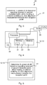
- Figure 4 illustrates schematically a network node and means for implementing methods of the present disclosure.
- the network node 12, 13 in which the present method may be implemented has been described in relation to figure 2 , and reference is also made to the description relating to figure 2 .
- the network node 12, 13 is configured for CoMP, and at least configured for UL CoMP, and it thus comprises or is arranged to control a number of reception points 35, 36.
- the network node 12, 13 may further comprise an interface device, in the figure indicated by an input/output device (I/O) 34 for communicating with other network entities, e.g. to communicate with other network nodes.
- I/O input/output device
- the network node 12, 13 comprises a processor 30 comprising any combination of one or more of a central processing unit (CPU), multiprocessor, microcontroller, digital signal processor (DSP), application specific integrated circuit etc. capable of executing software instructions stored in a memory 32, which can thus be a computer program product 32.
- processor 30 comprising any combination of one or more of a central processing unit (CPU), multiprocessor, microcontroller, digital signal processor (DSP), application specific integrated circuit etc. capable of executing software instructions stored in a memory 32, which can thus be a computer program product 32.
- the memory 32 can be any combination of read and write memory (RAM) and read only memory (ROM).
- the memory 32 also comprises persistent storage, which, for example, can be any single one or combination of magnetic memory, optical memory, solid state memory or even remotely mounted memory.
- a data memory 33 may also be provided for reading and/or storing data during execution of software instructions in the processor 30.
- the data memory 33 can be any combination of read and write memory (RAM) and read only memory (ROM).
- the processor 30 can be configured to execute any of the various embodiments of the method as has been described, e.g. in relation to figure 3 .
- a network node 12, 13 of a communication system 10 is provided for maintaining uplink time alignment.
- the communication system 10 comprises a first reception point 35 and a second reception point 36, and the network node 12 is configured to control the first reception point 35 and configured to serve a communication device 14.
- the network node 12 comprises a processor 30 and memory 31, the memory 31 containing instructions executable by the processor 30, whereby the network node 12 is operative to determine transmit power of the communication device 14 based on signaling from the communication device 14 received in the second reception point 36, while meeting a criterion enabling performing of an uplink time alignment measurement towards the first reception point 35.
- the criterion comprises a fixed threshold and the network node 12 is configured to determine by determining the transmit power based on a signal quality indicator for the signaling from the communication device 14 received in the second reception point 36 while keeping the transmit power such that signal quality indicator for the signaling received in the second reception point 36 is above the fixed threshold value.
- the fixed threshold value comprises a minimum value of a signal quality indicator for the signaling from the communication device 14 to be receivable by the first reception point 35.
- the signaling comprises a physical uplink shared channel, PUSCH, and/or physical uplink control channel, PUCCH, and wherein the network node 12 is configured to determine based on the physical uplink shared channel, PUSCH, and/or physical uplink control channel, PUCCH.
- the network node 12 is configured to determine by:
- the network node 12 is configured to determine by:
- the network node 12 is configured to determine by determining a first transmit power for transmission of a physical uplink control channel, PUCCH, based on the PUCCH received in the first reception point 35 and determining a second transmit power for transmission of a physical uplink shared channel, PUSCH, based on the PUSCH received in the second reception point 36, the network node 12 being configured to:
- the network node 12 is configured to perform the uplink alignment measurement based on the reception of the CQI report in the first reception point 35.
- the network node 12 is configured to perform the scheduling upon detecting a need of the communication device 14 for an updated timing advance value.
- the network node 12 is configured to:
- the network node 12 is configured to transmit a transmit power command to the communication device 14 based on the determined transmit power.
- the present disclosure also encompasses a computer program product 32 comprising a computer program 31 for implementing the methods as described, and a computer readable means on which the computer program 31 is stored.
- the computer program product 32 may be any combination of read and write memory (RAM) or read only memory (ROM).
- the computer program product 32 may also comprise persistent storage, which for example can be any single one or combination of magnetic memory, optical memory or solid state memory.
- the present teachings thus also encompass a computer program 31 for a network node 12 of a communication system 10 for maintaining uplink time alignment, the communication system 10 comprising a first reception point 35 and a second reception point 36, the network node 12 being configured to control the first reception point 35 and configured to serve a communication device 14.
- the computer program 31 comprises computer program code, which, when run on the network node 12 causes the network node 12 to determine transmit power of the communication device 14 based on signaling from the communication device 14 received in the second reception point 36, while meeting a criterion enabling performing of an uplink time alignment measurement towards the first reception point 35.
- the computer program product thus comprises instructions executable by the processor.
- Such instructions may be comprised in a computer program, or in one or more software modules or function modules.
- FIG. 5 An example of an implementation using function modules/ software modules is illustrated in figure 5 , in particular illustrating the network node 12 comprising function modules for implementing methods of the present disclosure.
- the network node 12 comprises means, e.g. a first function module 41, for determining transmit power of the communication device 14 based on signaling from the communication device 14 received in the second reception point 36, while meeting a criterion enabling performing of an uplink time alignment measurement towards the first reception point 35.
- Further means, e.g. function modules may be provided for implementing the various other features and embodiments that have been described.
- the means e.g. the function module 41, and further means, e.g. further function modules, can be implemented using software instructions such as computer program executing in a processor and/or using hardware, such as application specific integrated circuits, field programmable gate arrays, discrete logical components etc.
- UL CoMP is an attractive feature and more and more operators will use this type of functionality to manage the interference situation in their radio network when the traffic load increases.
- UL CoMP reception will also be an important functionality, particularly when introducing heterogeneous network deployments providing the freedom to basically receive the uplink signal in any reception point, not only in the serving reception point.
- the present disclosure addresses problems that might arise when trying to achieve the gains that can be expected when using UL CoMP.
- the present disclosure provides, in various embodiments, a method that will maintain proper time alignment measurements while using an uplink power control scheme based on signaling from best reception point. This will allow for e.g. simplified heterogeneous network deployments, improved utilization of the UL CoMP reception functionality, system throughput gains by reducing the interference situation in the network and improved cell edge performance experience in low power nodes by reducing the transmit power for UEs connected to high power nodes.
Description
- The technology disclosed herein relates generally to the field of wireless communication systems using coordinated multipoint, and in particular to timing measurements in such systems using uplink coordinated multipoint reception.
- A wireless communication system covers a geographical area which is divided into several radio coverage areas. Such radio coverage areas are often referred to as cells or sectors. Each radio coverage area is served by a radio base station (RBS), which may be denoted in different ways depending e.g. on radio access technology. For example, such RBS may be referred to as eNodeB or eNB for communication systems adapting to Long Term Evolution (LTE) standard. An access point (reception point/transmission point) refers to a set of co-located antennas that provide coverage to one radio coverage area. One RBS may serve one or several such radio coverage areas.
- Uplink Coordinated Multi-Point (UL CoMP) is a multi-antenna technique that commonly refers to utilizing received signals from more than one reception point, when performing reception for one communication device. The signals that are received by the various reception points can be combined and processed to obtain a final received signal, whereby also signals low in strength may be received with few errors. This can be compared to the presently more conventional case, where only one reception point, i.e. the serving reception point, is used when performing reception for one communication device.
- Uplink performance can be improved quite significantly by using UL CoMP, e.g. in heterogeneous (HetNet) network deployments. Apart of this gain comes from the fact that communication devices in a HetNet deployment that are served by macro RBS reception points but located quite close to a low power RBS reception point (e.g. a pico RBS reception point), can reduce their transmit power with a maintained service quality when using both the macro and pico reception points. Thereby the communication device radiates less interference towards the pico reception point.
-
US2012/0322494 (QUALCOMM INCORPORATED), published 20-12-2012, discloses an apparatus and method for controlling transmission power, wherein a serving NodeB and a non-serving NodeB are participating in a soft handover procedure. - While the combined signal quality is maintained by combining the signals from all the reception points (pico and macro in the above example) that are part of the UL CoMP reception, the signal quality in the serving reception point alone can fall below acceptable signal quality levels which are needed to perform uplink measurements such as measurements for uplink time alignment. These measurements are needed since e.g. control signaling on a physical uplink control channel (PUCCH) might only be received in the serving reception point. Furthermore, if the communication device does not receive a valid timing advance (TA) command during a configured time period, it will assume it is has lost uplink synchronization and will be forced to initiate a random access procedure prior to any physical uplink shared channel (PUSCH) or PUCCH transmission. Failure to measure uplink time alignment in the serving reception point would introduce this kind of unwanted behavior.
- When UL CoMP is used, the RBS has several alternatives of controlling the transmit power of communication devices. One way is to use a predefined signal reception quality in the reception point where the highest received signal quality is achieved, and base the transmit power thereon. The reception point having the highest received signal reception quality is not necessarily the serving reception point. This may in fact be a quite frequently occurring case, especially in heterogeneous network deployments with large differences in downlink output power, as illustrated in
figure 1 . Thecommunication system 1 comprises amacro RBS 2 and apico RBS 3, and the macro RBS 2 is typically using higher transmit power than the pico RBS 3. An uplink signal from acommunication device 4 may be received in thepico RBS 3 with a higher received signal reception quality (e.g. reference signal received power, RSRP) than in the macro RBS 2. The difference in downlink output power between thereception points pico RBS 3 and themacro eNB 2 based on RSRP may lead to choosing themacro RBS 2 as serving point in downlink, while the cell border based on pathloss would benefit from using thepico RBS 3 for uplink. - In such deployment scenarios, the transmit power control scheme of using a predefined signal reception quality has the benefit of ensuring that the
communication device 4 does not cause high interference towards the low power pico RBS 3 while using the high power macro RBS 2 as the serving reception point, hence avoiding high interference from e.g. cell-edge macro communication devices towards the communication devices connected to the low power pico RBS 3. - A drawback with using this transmit power control scheme together with UL CoMP is that the uplink signal quality in the serving reception point can become degraded to the point when e.g. uplink time alignment cannot be maintained towards the serving reception point.
- An objective of the present disclosure is to solve or at least alleviate at least the above mentioned problem.
- The invention is defined by the independent claims. Furthermore, the embodiments of the invention are those defined by the claims. Moreover, examples, aspects and descriptions, which are not covered by the claims are presented not as embodiments of the invention, but as background art or examples useful for understanding the invention. Further features and advantages of the present disclosure will become clear upon reading the following description and the accompanying drawings.
-
-
Figure 1 illustrates an UL CoMP in a heterogeneous deployment scenario. -
Figure 2 illustrates schematically an environment in which embodiments of the present disclosure may be implemented. -
Figure 3 illustrates a flow chart over steps of a method in a network node in accordance with the present disclosure. -
Figure 4 illustrates schematically a network node and means for implementing methods of the present disclosure. -
Figure 5 illustrates a network node comprising functions modules/ software modules for implementing methods of the present disclosure. - In the following description, for purposes of explanation and not limitation, specific details are set forth such as particular architectures, interfaces, techniques, etc. in order to provide a thorough understanding. In other instances, detailed descriptions of well-known devices, circuits, and methods are omitted so as not to obscure the description with unnecessary detail. Same reference numerals refer to same or similar elements throughout the description.
- As mentioned earlier, transmit power control of a communication device can be made towards the cell/ sector to which the communication has the best uplink signal quality. If having this type of transmit power control in a deployment using UL CoMP, then this may lead to the serving sector loosing uplink signal quality and necessary uplink measurements, e.g. for uplink time alignment, failing. Such situation may in particular arise in a HetNet deployment using UL CoMP reception, in which there maybe a large uplink/downlink unbalance as described earlier.
- Briefly, the present disclosure provides, in various embodiments, a method to assure adequate timing measurements and to maintain uplink time alignment in a wireless communication system using uplink coordinated multipoint (UL CoMP) reception. Various embodiments are thus disclosed for maintaining uplink time alignment while utilizing the benefits of UL CoMP together with uplink power control.
-
Figure 2 illustrates an environment in which aspects of the present disclosure may be implemented. Acommunication system 10, in which embodiments of the disclosure may be implemented, may be an LTE network. Thecommunication system 10 comprises a number ofnetwork nodes communication devices communication device network node network node particular communication device 14 from several reception points. Infigure 2 this is illustrated by arrows from thecommunication devices different reception points reception points single RBS particular communication device particular communication device 14, 16 (which of course may control all reception points with which the particular communication device communicates). The RBS serving acommunication device - In this regard, as a note of vocabulary, a reception point is typically chosen to be a serving reception point for a communication device based on downlink channel quality towards the communication device. The reception point towards which time alignment is to be maintained is typcially the serving reception point.
- It is noted that a particular network deployment in which embodiments of the present disclosure may be implemented comprise a HetNet scenario. The
communication system 10 illustrated infigure 2 may then comprise amacro RBS 12 and apico RBS 13, themacro RBS 12 being configured to use a higher transmit power than thepico RBS 13 and thus providing a larger coverage area than thepico RBS 13, which is configured to use a lower transmit power than themacro RBS 12 and reach users within a smaller coverage area. - The transmit power of the
communication devices communication device RBS communication device 14, 15 measures the power of the reference signal and may determine e.g. path loss to theRBS communication device communication device - The closed loop power control provides the
RBS communication device communication device communication device RBS communication device communication device - However, this latter feedback mechanism can also be used by the
RBS communication devices communication devices - One example of such a power control scheme is depicted in
figure 2 . In the following,communication devices figure 2 are referred to as UE2 and UE1, respectively, and communication devices in general are referred to as UE. Further, afirst network node 12 is referred to asmacro node 12, and asecond network node 13 is referred to aspico node 13. Both UE1 and UE2 are served by themacro node 12 since this decision is typically based on the received downlink RSRP in the UE. The uplink signal will be received in both themacro node 12 and thepico node 13 and the signal reception target for UE1 is maintained towards themacro node 12 since this radio link presents the best propagation path (radio link illustrated by continuous arrow between UE1 and macro node 12). Signaling from UE1 is received also bypico node 13, but this radio link (illustrated by dashed line between UE1 and pico node 13) is not as good propagation path as the radio link towards themacro node 12. UE2 is however experiencing a better propagation path towards the pico node 13 (illustrated by continuous arrow between UE2 and pico node 13) so the power reception target can be maintained towards thepico node 13 instead of themacro node 12. This means that the signal quality is maintained for UE2 by utilizing a different reception point (reception point indicated by reference numeral 36) than the serving reception point (reception point indicated by reference numeral 35). This also implies that the signal quality towards the servingreception point 35 alone could degrade to the point when uplink measurements that normally are measured in the servingreception point 35 cannot be maintained. The present disclosure provides different approaches to handle this kind of problems, i.e. approaches for maintaining uplink time alignment towards serving reception point. Thereby it is ensured that thecommunication devices - A first embodiment to maintain uplink time alignment towards the serving reception point is to make sure that the signal quality does not degrade beyond the possibilities for the serving reception point to perform adequate time alignment measurements. This may be realized by introducing a threshold, in particular a fixed power regulation threshold, that limits the degradation of the signal reception in the serving reception point when the power control algorithm tries to reduce the transmit power for the UE in relation to the reception point having the best propagation path. Such reception point, i.e. having best uplink propagation path towards a UE, is also denoted "best reception point". In particular, when the best reception point is receiving a signal quality above the predefined signal quality target, it would send a TPC to the UE to lower its transmit power. By using the fixed power regulation threshold, the best reception point is not allowed to lower the transmit power more than down to the fixed power regulation threshold, and the serving reception point will thus still be able to receive signaling from the UE or at least perform necessary measurements towards the UE, e.g. by being able to receive some signaling from the UE or by being able to make measurements on transmissions from the UE.
- The fixed power regulation threshold may be set for example based on experience and/or based on simulations. The fixed power regulation threshold may in particular be set in view of the serving reception point still being able to perform time alignment measurements, for example being able to perform time alignment measurements on a particular channel.
- In variations of the embodiment, the threshold may change adaptively depending on the success of carrying out the necessary measurements in the serving reception point. For example, when a successful measurement of the uplink time alignment has been carried out, the threshold value may be lowered. As another example, when a successful measurement of the uplink time alignment has been carried out, the threshold value may be removed for a while (e.g. setting it equal to zero), since the UE would have to move in relation to the serving reception point rather much before the timing advance value changes. If the movement of the UE is monitored, an indication of the need to update the time alignment may be received, whereby the fixed threshold may be re-set so that the time alignment measurements may again be carried out.
- Although providing a rather simple and straightforward implementation, the above embodiment may sometimes limit the amount of interference reduction that could be achieved. In particular, the best reception point is receiving signals from the UE on a higher power level than it would actually need to do in order to hear the UE (i.e. in order to receive signals from the UE), thereby allowing the serving reception point to also hear the UE.
- In a variation, the above algorithm may be used for PUSCH, so that this channel is power controlled towards all reception points while the fixed power regulation threshold is used to ensure a certain signal quality in the serving reception point. That is, the PUSCH is power controlled towards each reception point in that the transmit power target for the UE is set in relation to the best reception point among all the reception points receiving signals from the UE, but the fixed power regulation threshold is applied so that the serving reception point is able to receive signals from the UE. The PUCCH on the other hand may be power controlled only towards the serving reception point, and relies on that timing alignment is maintained properly in the serving reception point. The PUCCH is thus heard by the serving reception point since the UE sends PUCCH using sufficient power to be heard (as the UE is power controlled towards the serving reception point for this channel).
- In another variation, the fixed power regulation threshold algorithm is used for power controlling both PUSCH and PUCCH.
- In another embodiment, a scheduled bandwidth is limited to ensure a minimum signal quality at the serving reception point. A UE may become power limited; the UE has a maximum uplink transmit power limit (e.g. depending on the UE capability or limit provided by an RBS), and if the UE would like to use a higher uplink transmit power than this upper limit, e.g. based on RSRP, then it is prohibited to do this and it is said to be power limited.
- If the UE becomes power limited, a received power spectral density (PSD) in the reception point will depend on the scheduled bandwidth. If the bandwidth is too large, the received PSD in the serving reception point could be too small for reliably measure the timing advance. In an embodiment, the allowed scheduled bandwidth is therefore limited to ensure a certain signal quality (e.g. in terms of minimum PSD) in the serving reception point when the UE becomes power limited.
- If the UE becomes power limited, i.e. it cannot increase its transmit power further, then it may be allocated fewer communication resources (i.e. bandwidth). Thereby its signal power will increase in the fewer scheduled communication resources, and the received PSD is increased in the serving reception point which is then able to receive signaling from the UE. As a particular non-limiting numerical example to illustrate this, assume that the UE has a maximum transmit power of 1 W. If the UE is scheduled in 10 resource blocks (i.e. communication resources) it is thus allowed to transmit 0.1 W per resource block. However, if reducing the scheduled resource blocks by half, then it would be allowed to transmit 0.2 W per resource block of its scheduled 5 resource blocks. Such reduction of communication resources may be done during short periods of time, and may be repeated regularly or once in a while for allowing the serving reception point to receive signaling from the UE.
- This embodiment may also be combined with the previous embodiments. That is, as long as the UE is not power limited, the power control algorithm is adjusted to maintain a certain signal quality in the serving reception point. If the UE is power limited, it is no longer possible to improve signal quality by increasing power, and instead the scheduled bandwidth is limited to ensure a certain signal quality.
- In still another embodiment, an adaptive power regulation threshold may be used, the power regulation threshold being associated with expected changes in the UEs timing advance values.
- This embodiment takes advantage of the fact that the UE can move a significant distance, i.e. a significant period of time may elapse, before a change in transmit timing advance value is detected and a new timing advance value has to be signaled to the UE. It would be possible to neglect timing measurements in the serving reception point during a period of time. During these periods of time the UE is power controlled only towards the best reception point without any consideration to its serving reception point. This allows a maximum reduction of interference towards other reception points (since the UE uses lowest possible transmit power). When there is an indication of the need for an updated uplink timing advance measurement, TPC commands is sent from the best reception point ordering the UE to increase its transmit power to a level at which uplink timing measurements becomes possible in the serving reception point.
- Indications of need for an updated uplink timing advance measurement may for instance comprise the RBS determining the accuracy of the latest timing advance value for the UE, and if the accuracy is below a threshold value then that is taken as and indication of need to update the timing advance value by performing a measurement. Such an indication of the need to update the timing advance value may be realized for example by using Doppler shift to estimate the velocity of the UE. As another example, the indication of need to update the timing advance value may be realized by tracking changes of the timing advance value in the best reception point and communicating these changes to the serving point. The serving reception point may then use this information about changes in order to trigger a timing advance measurement cycle.
- Further, if the UE is power limited the scheduled bandwidth may need to be reduced to ensure a certain signal quality in the serving reception point. When the measurements have been successfully concluded the power and bandwidth constraints may be released and the UE may be power controlled towards the best serving point.
- In still another embodiment, adaptive uplink scheduling is used to measure timing advance on PUCCH. In such embodiment, the timing advance measurements are based on PUCCH and the PUCCH channel remains power controlled towards the serving reception point (as opposed to best reception point). In this case only the PUSCH channel will be power controlled towards the best reception point. As long as the UE is scheduled in uplink, the PUSCH channel is made to be used for all uplink transmissions including control information that are otherwise sent on PUCCH. The serving reception point may not be able to receive the PUSCH from the UE and in order to maintain the uplink synchronization towards serving reception point it is therefore important that the UE transmits on PUCCH channel when there is an indication that the timing advance value needs to be updated (such indications have been exemplified earlier). To ensure that this happens, i.e. that the UE transmits on the PUCCH when need arises, an UL scheduler may create UL scheduling gaps that are synchronized with the UE transmissions of periodic channel quality indicator (CQI) reports. With no scheduled uplink PUSCH resources the UE may then still send periodic CQI reports on PUCCH and these transmissions can be used for uplink timing advance measurements. It is noted that the content of the CQI report as such is unimportant for the purpose of determining the timing advance. However, since the UE is required to send the CQI-report regularly, and by forcing the UE to send it on the PUCCH (which is power controlled towards the serving reception point), a timing advance value can be determined towards the serving reception point based on received timing of the CQI-report.
- Stated differently, PUCCH is power controlled towards the serving reception point and PUSCH is power controlled towards the best reception point. By introducing the gaps in the UL PUSCH scheduling, in which gaps the UE sends CQI reports on the PUCCH, the timing advance measurements to the serving reception point are enabled.
- The various embodiments and features may be combined in a number of ways.
Figure 3 illustrates a flow chart over steps of a method in anetwork node method 20 for maintaining uplink time alignment may be performed in 12 of acommunication system 10, such as described in relation tofigure 2 . That is thecommunication system 10 comprising afirst reception point 35 and asecond reception point 36 and thenetwork node 12 being configured to control thefirst reception point 35 and configured to serve acommunication device 14. Themethod 20 comprises determining 21 transmit power of thecommunication device 14 based on signaling from thecommunication device 14 received in thesecond reception point 36, while meeting a criterion enabling performing of an uplink time alignment measurement towards thefirst reception point 35. The transmit power may thus be controlled towards the best reception point, whereby interference reduction is achieved. The transmit power is however determined such that it is ensured that the first reception point (e.g. being the serving reception point) may still be able to perform time alignment measurements, i.e. under this requirement. This requirement is ensured by determining the transmit power while simultaneously fulfilling a criterion, which may be chosen among several different criteria and is set such that the serving reception point can perform the necessary measurements. - It is noted that several second reception points could be used.
- In an embodiment, the criterion comprises a fixed threshold and the determining 21 comprises determining the transmit power based on a signal quality indicator for the signaling from the
communication device 14 received in thesecond reception point 36 while keeping the transmit power such that signal quality indicator for the signaling received in thesecond reception point 36 is above the fixed threshold value. - In a variation of the above embodiment, the fixed threshold value comprises a minimum value of a signal quality indicator for the signaling from the
communication device 14 to be receivable by thefirst reception point 35. The fixed threshold may thus be set so that the signal quality, e.g. received power, of the signaling received in thesecond reception point 36 is (just) high enough to be heard also by the first (i.e. serving)reception point 35. - In variations of the above two embodiments, the signaling comprises a physical uplink shared channel, PUSCH, and/or physical uplink control channel, PUCCH, and wherein the determining 21 is based on the physical uplink shared channel, PUSCH, and/or physical uplink control channel, PUCCH.
- In an embodiment, the determining 21 comprises:
- detecting accuracy of a timing advance adjustment towards the
first reception point 35 falling below a set threshold, and - increasing the transmit power until reaching a minimum value of a signal quality indicator for the signaling from the
communication device 14 to be receivable by thefirst reception point 35 or increasing transmit power until obtaining an accuracy of the timing advance adjustment above the set threshold. - In an embodiment, the determining 21 comprises:
- detecting accuracy of a timing advance adjustment towards the
first reception point 35 falling below a set threshold, and - reducing the number of communication resources allocated to the
communication device 14 until a minimum value of a signal quality indicator for the signaling from thecommunication device 14 to be receivable by thefirst reception point 35 is obtained or until an accuracy of the timing advance adjustment above the set threshold is obtained. - In an embodiment, the determining 21 comprises determining a first transmit power for transmission of a physical uplink control channel, PUCCH, based on the PUCCH received in the
first reception point 35 and determining a second transmit power for transmission of a physical uplink shared channel, PUSCH, based on the PUSCH received in thesecond reception point 36, themethod 20 further comprising: - scheduling PUSCH with a scheduling gap coinciding with a scheduled channel quality indicator, CQI, report, whereby the CQI report is sent on the PUCCH.
- In a variation of the above embodiment, the uplink alignment measurement is performed based on the reception of the CQI report in the
first reception point 35. - In variations of the above two embodiments, the scheduling is performed upon detecting a need of the
communication device 14 for an updated timing advance value. - In an embodiment, the
method 20 comprises: - establishing that the
communication device 14 is power limited, and - reducing the number of communication resources allocated to the
communication device 14. - In an embodiment, the
method 20 comprises transmitting a transmit power command to thecommunication device 14 based on the determined transmit power.Figure 4 illustrates schematically a network node and means for implementing methods of the present disclosure. Thenetwork node figure 2 , and reference is also made to the description relating tofigure 2 . Thenetwork node - The
network node - The
network node processor 30 comprising any combination of one or more of a central processing unit (CPU), multiprocessor, microcontroller, digital signal processor (DSP), application specific integrated circuit etc. capable of executing software instructions stored in amemory 32, which can thus be acomputer program product 32. - The
memory 32 can be any combination of read and write memory (RAM) and read only memory (ROM). Thememory 32 also comprises persistent storage, which, for example, can be any single one or combination of magnetic memory, optical memory, solid state memory or even remotely mounted memory. - A
data memory 33 may also be provided for reading and/or storing data during execution of software instructions in theprocessor 30. Thedata memory 33 can be any combination of read and write memory (RAM) and read only memory (ROM). - The
processor 30 can be configured to execute any of the various embodiments of the method as has been described, e.g. in relation tofigure 3 . In particular, anetwork node communication system 10 is provided for maintaining uplink time alignment. Thecommunication system 10 comprises afirst reception point 35 and asecond reception point 36, and thenetwork node 12 is configured to control thefirst reception point 35 and configured to serve acommunication device 14. Thenetwork node 12 comprises aprocessor 30 andmemory 31, thememory 31 containing instructions executable by theprocessor 30, whereby thenetwork node 12 is operative to determine transmit power of thecommunication device 14 based on signaling from thecommunication device 14 received in thesecond reception point 36, while meeting a criterion enabling performing of an uplink time alignment measurement towards thefirst reception point 35. - In an embodiment, the criterion comprises a fixed threshold and the
network node 12 is configured to determine by determining the transmit power based on a signal quality indicator for the signaling from thecommunication device 14 received in thesecond reception point 36 while keeping the transmit power such that signal quality indicator for the signaling received in thesecond reception point 36 is above the fixed threshold value. - In a variation of the above embodiment, the fixed threshold value comprises a minimum value of a signal quality indicator for the signaling from the
communication device 14 to be receivable by thefirst reception point 35. - In an embodiment, the signaling comprises a physical uplink shared channel, PUSCH, and/or physical uplink control channel, PUCCH, and wherein the
network node 12 is configured to determine based on the physical uplink shared channel, PUSCH, and/or physical uplink control channel, PUCCH. - In an embodiment, the
network node 12 is configured to determine by: - detecting accuracy of a timing advance adjustment towards the
first reception point 35 falling below a set threshold, and - increasing the transmit power until reaching a minimum value of a signal quality indicator for the signaling from the
communication device 14 to be receivable by thefirst reception point 35 or increasing transmit power until obtaining an accuracy of the timing advance adjustment above the set threshold. - In an embodiment, the
network node 12 is configured to determine by: - detecting accuracy of a timing advance adjustment towards the
first reception point 35 falling below a set threshold, and - reducing the number of communication resources allocated to the
communication device 14 until a minimum value of a signal quality indicator for the signaling from thecommunication device 14 to be receivable by thefirst reception point 35 is obtained or until an accuracy of the timing advance adjustment above the set threshold is obtained. - In an embodiment, wherein the
network node 12 is configured to determine by determining a first transmit power for transmission of a physical uplink control channel, PUCCH, based on the PUCCH received in thefirst reception point 35 and determining a second transmit power for transmission of a physical uplink shared channel, PUSCH, based on the PUSCH received in thesecond reception point 36, thenetwork node 12 being configured to: - schedule PUSCH with a scheduling gap coinciding with a scheduled channel quality indicator, CQI, report, whereby the CQI report is sent on the PUCCH.
- In a variation of the above embodiment, the
network node 12 is configured to perform the uplink alignment measurement based on the reception of the CQI report in thefirst reception point 35. - In variation of the above two embodiments, the
network node 12 is configured to perform the scheduling upon detecting a need of thecommunication device 14 for an updated timing advance value. - In an embodiment, the
network node 12 is configured to: - establish that the
communication device 14 is power limited, and - reduce the number of communication resources allocated to the
communication device 14. - In an embodiment, the
network node 12 is configured to transmit a transmit power command to thecommunication device 14 based on the determined transmit power. - The present disclosure also encompasses a
computer program product 32 comprising acomputer program 31 for implementing the methods as described, and a computer readable means on which thecomputer program 31 is stored. Thecomputer program product 32 may be any combination of read and write memory (RAM) or read only memory (ROM). Thecomputer program product 32 may also comprise persistent storage, which for example can be any single one or combination of magnetic memory, optical memory or solid state memory. - The present teachings thus also encompass a
computer program 31 for anetwork node 12 of acommunication system 10 for maintaining uplink time alignment, thecommunication system 10 comprising afirst reception point 35 and asecond reception point 36, thenetwork node 12 being configured to control thefirst reception point 35 and configured to serve acommunication device 14. Thecomputer program 31 comprises computer program code, which, when run on thenetwork node 12 causes thenetwork node 12 to determine transmit power of thecommunication device 14 based on signaling from thecommunication device 14 received in thesecond reception point 36, while meeting a criterion enabling performing of an uplink time alignment measurement towards thefirst reception point 35. - The computer program product, or the memory, thus comprises instructions executable by the processor. Such instructions may be comprised in a computer program, or in one or more software modules or function modules.
- An example of an implementation using function modules/ software modules is illustrated in
figure 5 , in particular illustrating thenetwork node 12 comprising function modules for implementing methods of the present disclosure. Thenetwork node 12 comprises means, e.g. afirst function module 41, for determining transmit power of thecommunication device 14 based on signaling from thecommunication device 14 received in thesecond reception point 36, while meeting a criterion enabling performing of an uplink time alignment measurement towards thefirst reception point 35. Further means, e.g. function modules, may be provided for implementing the various other features and embodiments that have been described. - The means, e.g. the
function module 41, and further means, e.g. further function modules, can be implemented using software instructions such as computer program executing in a processor and/or using hardware, such as application specific integrated circuits, field programmable gate arrays, discrete logical components etc. - The present disclosure provides a number of advantages. UL CoMP is an attractive feature and more and more operators will use this type of functionality to manage the interference situation in their radio network when the traffic load increases. UL CoMP reception will also be an important functionality, particularly when introducing heterogeneous network deployments providing the freedom to basically receive the uplink signal in any reception point, not only in the serving reception point. The present disclosure addresses problems that might arise when trying to achieve the gains that can be expected when using UL CoMP. In particular, the present disclosure provides, in various embodiments, a method that will maintain proper time alignment measurements while using an uplink power control scheme based on signaling from best reception point. This will allow for e.g. simplified heterogeneous network deployments, improved utilization of the UL CoMP reception functionality, system throughput gains by reducing the interference situation in the network and improved cell edge performance experience in low power nodes by reducing the transmit power for UEs connected to high power nodes.
- The disclosure has mainly been described herein with reference to a few embodiments. However, as is appreciated by a person skilled in the art, other embodiments than the particular ones disclosed herein are equally possible within the scope of the disclosure, as defined by the appended patent claims.
Claims (11)
- A method (20) for maintaining uplink time alignment performed by a network node (12) of a communication system (10) comprising a first reception point (35) and a second reception point (36), the network node (12) being configured to receive uplink signaling from the first and second reception points by uplink coordinated multipoint reception, configured to control the first reception point (35) and configured to serve a communication device (14), the method (20) comprising:- determining (21) transmit power of the communication device (14) based on signaling from the communication device (14) received via the second reception point (36), while meeting a criterion enabling performing of an uplink time alignment measurement towards the first reception point (35),
wherein the determining comprises:- detecting accuracy of a timing advance adjustment towards the first reception point (35) falling below a set threshold, and- increasing the transmit power until reaching a minimum value of a signal quality indicator for the signaling from the communication device (14) to be receivable by the first reception point (35) or increasing transmit power until obtaining an accuracy of the timing advance adjustment above the set threshold; and- transmitting a transmit power command to the communication device based on the determined transmit power. - The method (20) as claimed in claim 1, wherein the determining (21) comprises:- when the communication device (14) is power limited, reducing the number of communication resources allocated to the communication device (14) until a minimum value of a signal quality indicator for the signaling from the communication device (14) to be receivable by the first reception point (35) is obtained or until an accuracy of the timing advance adjustment above the set threshold is obtained.
- The method (20) as claimed in claim 1, wherein the determining (21) comprises determining a first transmit power for transmission of a physical uplink control channel, PUCCH, based on the PUCCH received in the first reception point (35) and determining a second transmit power for transmission of a physical uplink shared channel, PUSCH, based on the PUSCH received in the second reception point (36), the method (20) comprising:- scheduling PUSCH with a scheduling gap coinciding with a scheduled channel quality indicator, CQI, report, whereby the CQI report is sent on the PUCCH.
- The method (20) as claimed in claim 3, wherein the uplink alignment measurement is performed based on the reception of the CQI report in the first reception point (35).
- The method (20) as claimed in claim 3 or 4, wherein the scheduling is performed upon detecting a need of the communication device (14) for an updated timing advance value.
- A network node (12) of a communication system (10) for maintaining uplink time alignment, the communication system (10) comprising a first reception point (35) and a second reception point (36), the network node (12) being configured to receive uplink signaling from the first and second reception points by uplink coordinated multipoint reception, configured to control the first reception point (35) and configured to serve a communication device (14), the network node (12) comprising a processor (30) and memory (31), the memory (31) containing instructions executable by the processor (30), whereby the network node (12) is operative to:- determine transmit power of the communication device (14) based on signaling from the communication device (14) received via the second reception point (36), while meeting a criterion enabling performing of an uplink time alignment measurement towards the first reception point (35),
wherein the determination comprises:- detecting accuracy of a timing advance adjustment towards the first reception point (35) falling below a set threshold, and- increasing the transmit power until reaching a minimum value of a signal quality indicator for the signaling from the communication device (14) to be receivable by the first reception point (35) or increasing transmit power until obtaining an accuracy of the timing advance adjustment above the set threshold; and- transmit a transmit power command to the communication device based on the determined transmit power. - The network node (12) as claimed in claim 6, wherein the network node (12) is configured to determine by:- when the communication device (14) is power limited, reducing the number of communication resources allocated to the communication device (14) until a minimum value of a signal quality indicator for the signaling from the communication device (14) to be receivable by the first reception point (35) is obtained or until an accuracy of the timing advance adjustment above the set threshold is obtained.
- The network node (12) as claimed in claim 6, wherein the network node (12) is configured to determine by determining a first transmit power for transmission of a physical uplink control channel, PUCCH, based on the PUCCH received in the first reception point (35) and determining a second transmit power for transmission of a physical uplink shared channel, PUSCH, based on the PUSCH received in the second reception point (36), the network node (12) being configured to:- schedule PUSCH with a scheduling gap coinciding with a scheduled channel quality indicator, CQI, report, whereby the CQI report is sent on the PUCCH.
- The network node (12) as claimed in claim 8, wherein the network node (12) is configured to perform the uplink alignment measurement based on the reception of the CQI report in the first reception point (35).
- The network node (12) as claimed in claim 8 or 9, wherein the network node (12) is configured to perform the scheduling upon detecting a need of the communication device (14) for an updated timing advance value.
- A computer program (31) for a network node (12) of a communication system (10) for maintaining uplink time alignment, the communication system (10) comprising a first reception point (35) and a second reception point (36), the network node (12) being configured to receive uplink signaling from the first and second reception points by uplink coordinated multipoint reception, configured to control the first reception point (35) and configured to serve a communication device (14), the computer program (31) comprising computer program code, which, when run on the network node (12) causes the network node (12) to:- determine transmit power of the communication device (14) based on signaling from the communication device (14) received via the second reception point (36), while meeting a criterion enabling performing of an uplink time alignment measurement towards the first reception point (35),
wherein the determination comprises:- detecting accuracy of a timing advance adjustment towards the first reception point (35) falling below a set threshold, and- increasing the transmit power until reaching a minimum value of a signal quality indicator for the signaling from the communication device (14) to be receivable by the first reception point (35) or increasing transmit power until obtaining an accuracy of the timing advance adjustment above the set threshold; and- transmit a transmit power command to the communication device based on the determined transmit power.
Applications Claiming Priority (1)
| Application Number | Priority Date | Filing Date | Title |
|---|---|---|---|
| PCT/SE2013/051613 WO2015094075A1 (en) | 2013-12-20 | 2013-12-20 | Method and means for maintaining uplink time alignment |
Publications (2)
| Publication Number | Publication Date |
|---|---|
| EP3085171A1 EP3085171A1 (en) | 2016-10-26 |
| EP3085171B1 true EP3085171B1 (en) | 2021-03-24 |
Family
ID=50031484
Family Applications (1)
| Application Number | Title | Priority Date | Filing Date |
|---|---|---|---|
| EP13826789.3A Active EP3085171B1 (en) | 2013-12-20 | 2013-12-20 | Method and means for maintaining uplink time alignment |
Country Status (3)
| Country | Link |
|---|---|
| US (1) | US10091737B2 (en) |
| EP (1) | EP3085171B1 (en) |
| WO (1) | WO2015094075A1 (en) |
Families Citing this family (1)
| Publication number | Priority date | Publication date | Assignee | Title |
|---|---|---|---|---|
| US11785568B2 (en) | 2018-02-26 | 2023-10-10 | Telefonaktiebolaget Lm Ericsson (Publ) | Optimizing usage of a coordinated service |
Family Cites Families (9)
| Publication number | Priority date | Publication date | Assignee | Title |
|---|---|---|---|---|
| JP3358565B2 (en) | 1998-11-02 | 2002-12-24 | 日本電気株式会社 | Transmission power control method, transmission power control device, mobile station, base station, and control station |
| KR100459573B1 (en) * | 2001-08-25 | 2004-12-03 | 삼성전자주식회사 | Apparatus for transmitting/receiving uplink transmission power and high speed downlink shared channel power level in communication system using high speed downlink packet access scheme and method thereof |
| US8717976B2 (en) * | 2009-01-26 | 2014-05-06 | Lg Electronics Inc. | Method and apparatus for transmitting control information in wireless communications system that supports coordinated multi-point (CoMP) including multiple transmission points |
| JP5373055B2 (en) * | 2009-03-10 | 2013-12-18 | シャープ株式会社 | Mobile station apparatus, communication system, communication method, and program |
| US9420543B2 (en) * | 2010-12-10 | 2016-08-16 | Qualcomm Incorporated | Control of transmission power on high-speed dedicated physical control channel |
| EP2749094B1 (en) * | 2011-10-04 | 2018-06-06 | Telefonaktiebolaget LM Ericsson (publ) | Controlling uplink transmit power responsive to combination of received power control commands during soft handover in a communicaton system |
| US20130196707A1 (en) | 2012-01-29 | 2013-08-01 | Telefonaktiebolaget L M Ericsson (Publ) | User Equipment, Network Node and Methods Therein |
| CN102573011B (en) * | 2012-02-17 | 2015-05-20 | 大唐移动通信设备有限公司 | Access control method and equipment |
| EP2946630B1 (en) * | 2013-01-16 | 2020-05-27 | Interdigital Patent Holdings, Inc. | Discovery signal generation and reception |
-
2013
- 2013-12-20 WO PCT/SE2013/051613 patent/WO2015094075A1/en active Application Filing
- 2013-12-20 EP EP13826789.3A patent/EP3085171B1/en active Active
- 2013-12-20 US US15/102,307 patent/US10091737B2/en active Active
Non-Patent Citations (1)
| Title |
|---|
| None * |
Also Published As
| Publication number | Publication date |
|---|---|
| WO2015094075A1 (en) | 2015-06-25 |
| EP3085171A1 (en) | 2016-10-26 |
| US10091737B2 (en) | 2018-10-02 |
| US20170034786A1 (en) | 2017-02-02 |
Similar Documents
| Publication | Publication Date | Title |
|---|---|---|
| CN109861802B (en) | System and method for adaptive transmission in wireless networks | |
| KR101826111B1 (en) | Method for uplink-downlink interference mitigation in heterogeneous network | |
| US9781728B2 (en) | Method and apparatus for coordinating schedulers in a coordinated multi-point communication system | |
| EP2815605B1 (en) | Methods and devices for adjusting resource management procedures in heterogeneous communication networks based on cell information | |
| CN107735959B (en) | Mobility for beamforming systems | |
| KR101781209B1 (en) | Methods for controlling uplink transmission power in mobile communication systems | |
| CN106068618B (en) | Method and arrangement for inter-cell interference coordination | |
| US20150003268A1 (en) | Method and apparatus for scheduling user equipment | |
| KR20140090351A (en) | Method and apparatus for managing uplink adaptive modulation and coding in the mobile communication system | |
| US10085219B2 (en) | Power control in a wireless network | |
| TW201540011A (en) | Method and apparatus for coordinating inter-cell interference | |
| US9949222B2 (en) | Cellular base station and method of operation | |
| US9374793B2 (en) | Network node, user equipment, methods therein, computer program product, and a computer storage medium | |
| CN110326233B (en) | Method and apparatus for reception in a wireless communication system | |
| EP3085171B1 (en) | Method and means for maintaining uplink time alignment | |
| US11283501B2 (en) | Methods and apparatus relating to a wireless communication network that utilises beamforming | |
| WO2017109551A1 (en) | Method and apparatus for controlling channel state indicator reference signal (csi-rs) transmission | |
| JP2017200202A (en) | Method for reducing uplink-downlink interference in heterogeneous network | |
| WO2019185142A1 (en) | Uplink scheduling based on upper and lower snr targets | |
| EP3824667A1 (en) | Attenuating a signal from a cell, beam or frequency in a resource |
Legal Events
| Date | Code | Title | Description |
|---|---|---|---|
| PUAI | Public reference made under article 153(3) epc to a published international application that has entered the european phase |
Free format text: ORIGINAL CODE: 0009012 |
|
| 17P | Request for examination filed |
Effective date: 20160701 |
|
| AK | Designated contracting states |
Kind code of ref document: A1 Designated state(s): AL AT BE BG CH CY CZ DE DK EE ES FI FR GB GR HR HU IE IS IT LI LT LU LV MC MK MT NL NO PL PT RO RS SE SI SK SM TR |
|
| AX | Request for extension of the european patent |
Extension state: BA ME |
|
| DAX | Request for extension of the european patent (deleted) | ||
| STAA | Information on the status of an ep patent application or granted ep patent |
Free format text: STATUS: EXAMINATION IS IN PROGRESS |
|
| 17Q | First examination report despatched |
Effective date: 20180212 |
|
| GRAP | Despatch of communication of intention to grant a patent |
Free format text: ORIGINAL CODE: EPIDOSNIGR1 |
|
| STAA | Information on the status of an ep patent application or granted ep patent |
Free format text: STATUS: GRANT OF PATENT IS INTENDED |
|
| GRAS | Grant fee paid |
Free format text: ORIGINAL CODE: EPIDOSNIGR3 |
|
| INTG | Intention to grant announced |
Effective date: 20210122 |
|
| GRAA | (expected) grant |
Free format text: ORIGINAL CODE: 0009210 |
|
| STAA | Information on the status of an ep patent application or granted ep patent |
Free format text: STATUS: THE PATENT HAS BEEN GRANTED |
|
| AK | Designated contracting states |
Kind code of ref document: B1 Designated state(s): AL AT BE BG CH CY CZ DE DK EE ES FI FR GB GR HR HU IE IS IT LI LT LU LV MC MK MT NL NO PL PT RO RS SE SI SK SM TR |
|
| REG | Reference to a national code |
Ref country code: GB Ref legal event code: FG4D |
|
| REG | Reference to a national code |
Ref country code: CH Ref legal event code: EP |
|
| REG | Reference to a national code |
Ref country code: DE Ref legal event code: R096 Ref document number: 602013076473 Country of ref document: DE |
|
| REG | Reference to a national code |
Ref country code: IE Ref legal event code: FG4D |
|
| REG | Reference to a national code |
Ref country code: AT Ref legal event code: REF Ref document number: 1375788 Country of ref document: AT Kind code of ref document: T Effective date: 20210415 |
|
| REG | Reference to a national code |
Ref country code: NL Ref legal event code: FP |
|
| REG | Reference to a national code |
Ref country code: LT Ref legal event code: MG9D |
|
| PG25 | Lapsed in a contracting state [announced via postgrant information from national office to epo] |
Ref country code: NO Free format text: LAPSE BECAUSE OF FAILURE TO SUBMIT A TRANSLATION OF THE DESCRIPTION OR TO PAY THE FEE WITHIN THE PRESCRIBED TIME-LIMIT Effective date: 20210624 Ref country code: BG Free format text: LAPSE BECAUSE OF FAILURE TO SUBMIT A TRANSLATION OF THE DESCRIPTION OR TO PAY THE FEE WITHIN THE PRESCRIBED TIME-LIMIT Effective date: 20210624 Ref country code: GR Free format text: LAPSE BECAUSE OF FAILURE TO SUBMIT A TRANSLATION OF THE DESCRIPTION OR TO PAY THE FEE WITHIN THE PRESCRIBED TIME-LIMIT Effective date: 20210625 Ref country code: FI Free format text: LAPSE BECAUSE OF FAILURE TO SUBMIT A TRANSLATION OF THE DESCRIPTION OR TO PAY THE FEE WITHIN THE PRESCRIBED TIME-LIMIT Effective date: 20210324 Ref country code: HR Free format text: LAPSE BECAUSE OF FAILURE TO SUBMIT A TRANSLATION OF THE DESCRIPTION OR TO PAY THE FEE WITHIN THE PRESCRIBED TIME-LIMIT Effective date: 20210324 |
|
| PG25 | Lapsed in a contracting state [announced via postgrant information from national office to epo] |
Ref country code: SE Free format text: LAPSE BECAUSE OF FAILURE TO SUBMIT A TRANSLATION OF THE DESCRIPTION OR TO PAY THE FEE WITHIN THE PRESCRIBED TIME-LIMIT Effective date: 20210324 Ref country code: RS Free format text: LAPSE BECAUSE OF FAILURE TO SUBMIT A TRANSLATION OF THE DESCRIPTION OR TO PAY THE FEE WITHIN THE PRESCRIBED TIME-LIMIT Effective date: 20210324 Ref country code: LV Free format text: LAPSE BECAUSE OF FAILURE TO SUBMIT A TRANSLATION OF THE DESCRIPTION OR TO PAY THE FEE WITHIN THE PRESCRIBED TIME-LIMIT Effective date: 20210324 |
|
| REG | Reference to a national code |
Ref country code: AT Ref legal event code: MK05 Ref document number: 1375788 Country of ref document: AT Kind code of ref document: T Effective date: 20210324 |
|
| PG25 | Lapsed in a contracting state [announced via postgrant information from national office to epo] |
Ref country code: SM Free format text: LAPSE BECAUSE OF FAILURE TO SUBMIT A TRANSLATION OF THE DESCRIPTION OR TO PAY THE FEE WITHIN THE PRESCRIBED TIME-LIMIT Effective date: 20210324 Ref country code: AT Free format text: LAPSE BECAUSE OF FAILURE TO SUBMIT A TRANSLATION OF THE DESCRIPTION OR TO PAY THE FEE WITHIN THE PRESCRIBED TIME-LIMIT Effective date: 20210324 Ref country code: LT Free format text: LAPSE BECAUSE OF FAILURE TO SUBMIT A TRANSLATION OF THE DESCRIPTION OR TO PAY THE FEE WITHIN THE PRESCRIBED TIME-LIMIT Effective date: 20210324 Ref country code: CZ Free format text: LAPSE BECAUSE OF FAILURE TO SUBMIT A TRANSLATION OF THE DESCRIPTION OR TO PAY THE FEE WITHIN THE PRESCRIBED TIME-LIMIT Effective date: 20210324 Ref country code: EE Free format text: LAPSE BECAUSE OF FAILURE TO SUBMIT A TRANSLATION OF THE DESCRIPTION OR TO PAY THE FEE WITHIN THE PRESCRIBED TIME-LIMIT Effective date: 20210324 |
|
| PG25 | Lapsed in a contracting state [announced via postgrant information from national office to epo] |
Ref country code: SK Free format text: LAPSE BECAUSE OF FAILURE TO SUBMIT A TRANSLATION OF THE DESCRIPTION OR TO PAY THE FEE WITHIN THE PRESCRIBED TIME-LIMIT Effective date: 20210324 Ref country code: RO Free format text: LAPSE BECAUSE OF FAILURE TO SUBMIT A TRANSLATION OF THE DESCRIPTION OR TO PAY THE FEE WITHIN THE PRESCRIBED TIME-LIMIT Effective date: 20210324 Ref country code: PL Free format text: LAPSE BECAUSE OF FAILURE TO SUBMIT A TRANSLATION OF THE DESCRIPTION OR TO PAY THE FEE WITHIN THE PRESCRIBED TIME-LIMIT Effective date: 20210324 Ref country code: PT Free format text: LAPSE BECAUSE OF FAILURE TO SUBMIT A TRANSLATION OF THE DESCRIPTION OR TO PAY THE FEE WITHIN THE PRESCRIBED TIME-LIMIT Effective date: 20210726 Ref country code: ES Free format text: LAPSE BECAUSE OF FAILURE TO SUBMIT A TRANSLATION OF THE DESCRIPTION OR TO PAY THE FEE WITHIN THE PRESCRIBED TIME-LIMIT Effective date: 20210324 Ref country code: IS Free format text: LAPSE BECAUSE OF FAILURE TO SUBMIT A TRANSLATION OF THE DESCRIPTION OR TO PAY THE FEE WITHIN THE PRESCRIBED TIME-LIMIT Effective date: 20210724 |
|
| REG | Reference to a national code |
Ref country code: DE Ref legal event code: R097 Ref document number: 602013076473 Country of ref document: DE |
|
| PG25 | Lapsed in a contracting state [announced via postgrant information from national office to epo] |
Ref country code: AL Free format text: LAPSE BECAUSE OF FAILURE TO SUBMIT A TRANSLATION OF THE DESCRIPTION OR TO PAY THE FEE WITHIN THE PRESCRIBED TIME-LIMIT Effective date: 20210324 Ref country code: DK Free format text: LAPSE BECAUSE OF FAILURE TO SUBMIT A TRANSLATION OF THE DESCRIPTION OR TO PAY THE FEE WITHIN THE PRESCRIBED TIME-LIMIT Effective date: 20210324 |
|
| PLBE | No opposition filed within time limit |
Free format text: ORIGINAL CODE: 0009261 |
|
| STAA | Information on the status of an ep patent application or granted ep patent |
Free format text: STATUS: NO OPPOSITION FILED WITHIN TIME LIMIT |
|
| PG25 | Lapsed in a contracting state [announced via postgrant information from national office to epo] |
Ref country code: SI Free format text: LAPSE BECAUSE OF FAILURE TO SUBMIT A TRANSLATION OF THE DESCRIPTION OR TO PAY THE FEE WITHIN THE PRESCRIBED TIME-LIMIT Effective date: 20210324 |
|
| 26N | No opposition filed |
Effective date: 20220104 |
|
| PG25 | Lapsed in a contracting state [announced via postgrant information from national office to epo] |
Ref country code: IS Free format text: LAPSE BECAUSE OF FAILURE TO SUBMIT A TRANSLATION OF THE DESCRIPTION OR TO PAY THE FEE WITHIN THE PRESCRIBED TIME-LIMIT Effective date: 20210724 |
|
| PG25 | Lapsed in a contracting state [announced via postgrant information from national office to epo] |
Ref country code: MC Free format text: LAPSE BECAUSE OF FAILURE TO SUBMIT A TRANSLATION OF THE DESCRIPTION OR TO PAY THE FEE WITHIN THE PRESCRIBED TIME-LIMIT Effective date: 20210324 |
|
| REG | Reference to a national code |
Ref country code: CH Ref legal event code: PL |
|
| REG | Reference to a national code |
Ref country code: BE Ref legal event code: MM Effective date: 20211231 |
|
| PG25 | Lapsed in a contracting state [announced via postgrant information from national office to epo] |
Ref country code: LU Free format text: LAPSE BECAUSE OF NON-PAYMENT OF DUE FEES Effective date: 20211220 Ref country code: IE Free format text: LAPSE BECAUSE OF NON-PAYMENT OF DUE FEES Effective date: 20211220 |
|
| PG25 | Lapsed in a contracting state [announced via postgrant information from national office to epo] |
Ref country code: FR Free format text: LAPSE BECAUSE OF NON-PAYMENT OF DUE FEES Effective date: 20211231 Ref country code: BE Free format text: LAPSE BECAUSE OF NON-PAYMENT OF DUE FEES Effective date: 20211231 |
|
| PG25 | Lapsed in a contracting state [announced via postgrant information from national office to epo] |
Ref country code: LI Free format text: LAPSE BECAUSE OF NON-PAYMENT OF DUE FEES Effective date: 20211231 Ref country code: CH Free format text: LAPSE BECAUSE OF NON-PAYMENT OF DUE FEES Effective date: 20211231 |
|
| PG25 | Lapsed in a contracting state [announced via postgrant information from national office to epo] |
Ref country code: IT Free format text: LAPSE BECAUSE OF FAILURE TO SUBMIT A TRANSLATION OF THE DESCRIPTION OR TO PAY THE FEE WITHIN THE PRESCRIBED TIME-LIMIT Effective date: 20210324 |
|
| PGFP | Annual fee paid to national office [announced via postgrant information from national office to epo] |
Ref country code: NL Payment date: 20221226 Year of fee payment: 10 |
|
| PG25 | Lapsed in a contracting state [announced via postgrant information from national office to epo] |
Ref country code: HU Free format text: LAPSE BECAUSE OF FAILURE TO SUBMIT A TRANSLATION OF THE DESCRIPTION OR TO PAY THE FEE WITHIN THE PRESCRIBED TIME-LIMIT; INVALID AB INITIO Effective date: 20131220 |
|
| PGFP | Annual fee paid to national office [announced via postgrant information from national office to epo] |
Ref country code: DE Payment date: 20221228 Year of fee payment: 10 |
|
| PG25 | Lapsed in a contracting state [announced via postgrant information from national office to epo] |
Ref country code: CY Free format text: LAPSE BECAUSE OF FAILURE TO SUBMIT A TRANSLATION OF THE DESCRIPTION OR TO PAY THE FEE WITHIN THE PRESCRIBED TIME-LIMIT Effective date: 20210324 |
|
| PGFP | Annual fee paid to national office [announced via postgrant information from national office to epo] |
Ref country code: GB Payment date: 20231227 Year of fee payment: 11 |