EP2749094B1 - Controlling uplink transmit power responsive to combination of received power control commands during soft handover in a communicaton system - Google Patents
Controlling uplink transmit power responsive to combination of received power control commands during soft handover in a communicaton system Download PDFInfo
- Publication number
- EP2749094B1 EP2749094B1 EP12743789.5A EP12743789A EP2749094B1 EP 2749094 B1 EP2749094 B1 EP 2749094B1 EP 12743789 A EP12743789 A EP 12743789A EP 2749094 B1 EP2749094 B1 EP 2749094B1
- Authority
- EP
- European Patent Office
- Prior art keywords
- transmission power
- control channel
- dedicated physical
- parameter
- physical control
- Prior art date
- Legal status (The legal status is an assumption and is not a legal conclusion. Google has not performed a legal analysis and makes no representation as to the accuracy of the status listed.)
- Not-in-force
Links
- 230000005540 biological transmission Effects 0.000 claims description 122
- 238000000034 method Methods 0.000 claims description 33
- 238000004891 communication Methods 0.000 description 21
- 238000010586 diagram Methods 0.000 description 16
- 230000006870 function Effects 0.000 description 9
- 238000004590 computer program Methods 0.000 description 7
- 238000012545 processing Methods 0.000 description 7
- 230000004044 response Effects 0.000 description 6
- 230000011664 signaling Effects 0.000 description 5
- 238000013459 approach Methods 0.000 description 3
- 238000013519 translation Methods 0.000 description 2
- 101000741965 Homo sapiens Inactive tyrosine-protein kinase PRAG1 Proteins 0.000 description 1
- 102100038659 Inactive tyrosine-protein kinase PRAG1 Human genes 0.000 description 1
- 241001025261 Neoraja caerulea Species 0.000 description 1
- 230000001413 cellular effect Effects 0.000 description 1
- 238000010276 construction Methods 0.000 description 1
- 238000013500 data storage Methods 0.000 description 1
- 230000000694 effects Effects 0.000 description 1
- 238000004519 manufacturing process Methods 0.000 description 1
- 230000003287 optical effect Effects 0.000 description 1
- 238000012552 review Methods 0.000 description 1
- 239000004065 semiconductor Substances 0.000 description 1
Images

Classifications
-
- H—ELECTRICITY
- H04—ELECTRIC COMMUNICATION TECHNIQUE
- H04W—WIRELESS COMMUNICATION NETWORKS
- H04W52/00—Power management, e.g. TPC [Transmission Power Control], power saving or power classes
- H04W52/04—TPC
- H04W52/38—TPC being performed in particular situations
- H04W52/40—TPC being performed in particular situations during macro-diversity or soft handoff
-
- H—ELECTRICITY
- H04—ELECTRIC COMMUNICATION TECHNIQUE
- H04W—WIRELESS COMMUNICATION NETWORKS
- H04W52/00—Power management, e.g. TPC [Transmission Power Control], power saving or power classes
- H04W52/04—TPC
- H04W52/18—TPC being performed according to specific parameters
- H04W52/28—TPC being performed according to specific parameters using user profile, e.g. mobile speed, priority or network state, e.g. standby, idle or non transmission
- H04W52/286—TPC being performed according to specific parameters using user profile, e.g. mobile speed, priority or network state, e.g. standby, idle or non transmission during data packet transmission, e.g. high speed packet access [HSPA]
-
- H—ELECTRICITY
- H04—ELECTRIC COMMUNICATION TECHNIQUE
- H04W—WIRELESS COMMUNICATION NETWORKS
- H04W52/00—Power management, e.g. TPC [Transmission Power Control], power saving or power classes
- H04W52/04—TPC
- H04W52/06—TPC algorithms
- H04W52/14—Separate analysis of uplink or downlink
- H04W52/146—Uplink power control
-
- H—ELECTRICITY
- H04—ELECTRIC COMMUNICATION TECHNIQUE
- H04W—WIRELESS COMMUNICATION NETWORKS
- H04W52/00—Power management, e.g. TPC [Transmission Power Control], power saving or power classes
- H04W52/04—TPC
- H04W52/06—TPC algorithms
- H04W52/16—Deriving transmission power values from another channel
-
- H—ELECTRICITY
- H04—ELECTRIC COMMUNICATION TECHNIQUE
- H04W—WIRELESS COMMUNICATION NETWORKS
- H04W52/00—Power management, e.g. TPC [Transmission Power Control], power saving or power classes
- H04W52/04—TPC
- H04W52/18—TPC being performed according to specific parameters
- H04W52/24—TPC being performed according to specific parameters using SIR [Signal to Interference Ratio] or other wireless path parameters
- H04W52/243—TPC being performed according to specific parameters using SIR [Signal to Interference Ratio] or other wireless path parameters taking into account interferences
- H04W52/244—Interferences in heterogeneous networks, e.g. among macro and femto or pico cells or other sector / system interference [OSI]
-
- H—ELECTRICITY
- H04—ELECTRIC COMMUNICATION TECHNIQUE
- H04W—WIRELESS COMMUNICATION NETWORKS
- H04W52/00—Power management, e.g. TPC [Transmission Power Control], power saving or power classes
- H04W52/04—TPC
- H04W52/30—TPC using constraints in the total amount of available transmission power
- H04W52/32—TPC of broadcast or control channels
- H04W52/325—Power control of control or pilot channels
Definitions
- the present invention relates to wireless communication systems and, more particularly, systems and methods that control uplink transmit power from user equipment nodes to network nodes.
- WCDMA Wideband Code Division Multiple Access
- 3GPP 3rd Generation Partnership Project
- Soft handover is an important feature in all WCDMA systems. With soft handover, User Equipment Nodes (UEs) are effectively connected to several base stations at the same time. This improves reliability, since a UE that moves from one cell to another establishes a link to the new cell, before the link to the old cell is torn down.
- UEs User Equipment Nodes
- the way that soft handover is combined with transmit power control also limits uplink (UL) interference in soft handover scenarios.
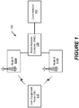
- the system 100 includes a UE 110 that communicates with two base stations (also referred to as "Node Bs" and “network nodes” herein) 120a and 120b through a radio air interface.
- the base stations 120a-b are controlled by a radio network controller (RNC) 130 and connected to a core network 140.
- RNC radio network controller
- a UE located at a border of one cell will cause uplink interference to neighboring cell(s). This interference can be particularly problematic because the UE located at the cell border (cell edge) will typically be transmitting near an upper range of its UL transmit power.
- HSPA High Speed Packet Access
- Soft handover can be used to reduce uplink interference to the neighboring cell(s).
- UEs at the border between two cells are connected to both (several in the general case) cells. The UEs therefore transmit data to both cells and receive data from both cells.
- Transmit power control is another important operation in WCDMA UL, since the channels within one cell are non-orthogonal: a transmission from one UE can strongly interfere with a transmission from another UE.
- the uplink and downlink communications are power controlled.
- the UE signals to a base station how it shall regulate its downlink transmission power.
- the base station signals to the UE how it shall regulate its uplink transmission power.
- a new transmit power control (TPC) command can be signaled every slot (e.g., 1500 TPC commands per second). Accordingly, at 1500 times per second, each UE can be commanded to either increase or decrease its transmit power by a predetermined step.
- the base station can control the UL packet error rate performance and UL interference by controlling the transmission power of the UE. As the UE increases its transmission power the experienced signal to interference ratio at the base station will in general increase. An increased signal to interference ratio will result in a lower packet error rate. In this way the base station can tune the uplink packet error rate.
- a UE In soft handover, a UE is receiving power control commands from more than one cell. Based on the received signal, each cell commands the UE to either increase or decrease its transmit power. The UE thus receives several, possibly conflicting, transmit power commands. The power control commands from the cells are combined to decide if the UE should either increase or decrease its transmit power. To combine the power control commands, the UE follows an operational rule that if any power control commands contain a DOWN request, the UE reduces its transmit power.
- a UE transmits data and control information on physical channels that can include Dedicated Physical Control CHannel (DPCCH), Enhanced-DPCCH (E-DPCCH), Enhanced Dedicated Physical Data CHannel (E-DPDCH), and High-Speed DPCCH (HS-DPCCH).
- the DPCCH transmits pilot bits that are known by the base station and also Layer 1 control information. The pilot bits are used as a reference by the base station to estimate the radio channel conditions (e.g. searcher, channel estimation, frequency offset estimation, and signal to interference ratio).
- the E-DPCCH transmits control information related to the enhanced dedicated physical data channel.
- the E-DPDCH transmits the data bits.
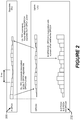
- Figure 2 illustrates graphs of transmission power levels and associated Transmission Power Control (TPC) commands that may be transmitted from a base station to a UE and, vice versa, from the UE to the base station to control the transmission power levels in the downlink and uplink directions.
- the base station measures the UL signal-to-interference ratio (SIR) on the DPCCH and compares it with a target value of the SIR. When the measured SIR is above the target SIR, the base station signals to the UE to decrease its transmission power. When the measured SIR is below the target SIR, the base station signals to the UE to increase its transmission power.
- the UL-TPC (Up Link Transmission Power Control) commands are signaled to the UE on the downlink (DL) channel F-DPCH (Fractional Dedicated Physical CHannel).
- DL downlink
- F-DPCH Fractional Dedicated Physical CHannel
- the UE measures the quality of the F-DPCH that it receives from the base station.
- the UE signals to the base station that it can decrease the transmission power on the F-DPCH.
- the UE signals to the base station to increase the transmission power on the F-DPCH.
- the DL-TPC commands are sent to the base station on the uplink channel DPCCH.
- the transmission power level of the E-DPCCH and the E-DPDCH may be controlled in response to a power offset relative to the transmission power level of the DPCCH.
- the TPC commands control the UE transmit power for DPCCH (P DPDCH ).
- the ⁇ parameter values are computed based on quantized amplitude ratios, which are translated from ⁇ ACK , ⁇ NACK , and ⁇ CQI signaling. Computation of ⁇ parameter values is explained in 3GPP TS 25.213 V10.0.0 (2010-09), Sect. 4.3.1.2, and translation of ⁇ ACK , ⁇ NACK , and ⁇ CQI signaling into ⁇ parameter values is explained in 3GPP TS 25.214 V10.0.0 (2010-09), Sect. 5.1.2.5A.
- Figure 3 illustrates a UE 110 that is connected to two base stations 120a and 120b in a heterogeneous network.
- One of the base stations 120b is a low power node (e.g., pico node) having significantly lower transmission power than the other base station 120a (e.g., macro node).
- Cell selection is typically based on downlink received power, with the illustrated UE 110 typically connected to the base station 120a or 120b from which it receives the highest transmit power, including effects of the different base station transmission powers.
- the UE 110 enters soft handover.
- the above described operational rule for combining power control commands received from different base stations is intended to ensure that data reaches one of the cells involved in a soft handover.
- the HS-DPCCH must reach one specific cell out of the cells involved in the soft handover, the so-called serving HS cell.
- the serving HS cell is the cell from which the high-speed downlink shared channel (HS-DSCH) is transmitted.
- the HS-DPCCH carried channel quality reports (CQIs) and ACK/NACKs that must reach the serving HS cell within a short delay (in the order of a few milliseconds).
- the document EP 1 494 366 A1 discloses a method for controlling uplink transmit power of a HS-DPCCH when the UE is in soft handover.
- the DPCCH transmit power may be reduced so that the HS-DPCCH is only received in the non-serving cell.
- the parameter ⁇ HS may be increased by a certain amount when the UE 110 enters soft handover. However, such an increase may be unnecessary in some cases, resulting in too high of an interference level (an unnecessary interference level).
- the cell-border can be quite close to the low power base station 120b.
- the low power base station 120b will receive a correspondingly very strong signal from the UE 110, and it will subsequently order the UE 110 to reduce it transmit power quite significantly.
- the signal received at the high power base station 120a (which may still be serving HE cell), will be quite weak, and using a fixed, large offset ⁇ HS will be insufficient for the high power base station 120a to properly receive the signal from the UE 110.
- CoMP Coordinated Multi-Point
- the invention is defined by a method according to claim 1 and a user equipment according to claim 10.
- Some embodiments of the present invention may provide improved power control during soft handover of a user equipment node (UE) between base stations.
- UE user equipment node
- Some embodiments are directed to a method by a UE for controlling uplink transmission power during soft handover of the UE from a first base station to a second base station.
- a transmission power control (TPC) command is received from each of the first and second base stations during the soft handover.
- the UE controls uplink transmission power of a high-speed dedicated physical control channel responsive to the received TPC commands.
- the UE can receive conflicting TPC commands from the base stations.
- the uplink transmission power of the high-speed dedicated physical control channel can be more robustly controlled so it can be received by whichever of the base stations is operating as a high-speed serving cell for the UE while avoiding unnecessary interference to the other base station.
- the UE determines a parameter ( ⁇ HS ) responsive to a combination of the received TPC commands, and controls the uplink transmission power of the high speed dedicated physical control channel responsive to a result of multiplying the parameter ( ⁇ HS ) and a transmission power level by the UE of a dedicated physical control channel.
- the UE determines the parameter ( ⁇ HS ) by determining a maximum value ⁇ HS max of the parameter ( ⁇ HS ), and determining when a condition occurs that at least one of the TPC commands received from the first and second base stations contains a request for the UE to decrease transmission power of the dedicated physical control channel and the parameter ( ⁇ HS ) is less than the maximum value ⁇ HS max .
- the UE responds to the determination that the condition occurred by reducing the uplink transmission power by the UE of the dedicated physical control channel. Accordingly, when conflicting TPC commands are received from the base stations, the UE will choose to decrease the uplink transmission power when the recited condition occurs while avoiding unnecessary interference to the other base station.
- the first base station is a serving high-speed cell for the UE for communication of signals to the UE on a high-speed downlink shared channel.
- the UE determines when a condition occurs that the TPC command received from the first base station contains a request for the UE to decrease transmission power of the dedicated physical control channel.
- the UE responds to the determination that the condition occurred by reducing the uplink transmission power by the UE of the dedicated physical control channel. Accordingly, when conflicting TPC commands are received from the base stations, the UE will choose to decrease the uplink transmission power when the serving HS first base station requests the UE to decrease transmission power.
- the first base station is a serving high-speed cell for the UE for communication of signals to the UE on a high-speed downlink shared channel.
- the UE determines the parameter ( ⁇ HS ) by determining when a condition occurs that the UE reduced the uplink transmission power of the dedicated physical control channel and the TPC command received from the first base station contains a request for the UE to increase transmission power of the dedicated physical control channel.
- the UE responds to the determination that the condition occurred by increasing the parameter ( ⁇ HS ) to increase the uplink transmission power by the UE of the high-speed dedicated physical control channel.
- the first base station is a serving high-speed cell for the UE for communication of signals to the UE on a high-speed downlink shared channel.
- the UE determines the parameter ( ⁇ HS ) by determining when a condition occurs that the TPC command received from the first base station contains a request for the UE to decrease transmission power of the dedicated physical control channel.
- the UE responds to the determination that the condition occurred by resetting the parameter ( ⁇ HS ) to a predefined nominal value responsive to the determination that the condition occurred.
- the UE may increase the parameter ( ⁇ HS ) by a fixed step size responsive to the TPC commands containing a request for the UE to increase transmission power of the high-speed dedicated physical control channel.
- the UE may alternatively access a table that defines values of the parameter ( ⁇ HS ) and corresponding step-sizes, using a present value of the parameter ( ⁇ HS ) as an index to look-up one of the step-sizes, and add the looked-up one of the step-sizes to the present value of the parameter ( ⁇ HS ) to generate a new value for the parameter ( ⁇ HS ) used to control the uplink transmission power of the high-speed dedicated physical control channel.
- a corresponding UE that includes a transceiver and a controller circuit.
- the transceiver receives a TPC command from each of a first base station and a second base station during soft handover of the UE from the first base station to the second base station.
- the controller circuit controls uplink transmission power by the transceiver of a high-speed dedicated physical control channel responsive to the received TPC commands.
- Various embodiments of the present invention are directed to controlling uplink transmission power between base stations (e.g., a Node B) and a UE during soft handover.
- base stations e.g., a Node B
- UE User Equipment
- FIG. 1 a pair of base stations are shown in Figure 1 , it is to be understood that the UE may communicate with any number of base stations during soft handover as controlled by predefined soft handover operations and methods.
- the UE 110 may be a mobile telephone ("cellular" telephone), a data terminal, and/or another processing device with wireless communication capability, such as, without limitation, a portable computer, a pocket computer, a hand-held computer, a laptop computer, an electronic book reader, and/or a video game console.
- cellular mobile telephone
- data terminal a data terminal
- another processing device with wireless communication capability such as, without limitation, a portable computer, a pocket computer, a hand-held computer, a laptop computer, an electronic book reader, and/or a video game console.
- the UE 110 communicates with the base stations (e.g., Node Bs) 120a and 120b, and dynamically controls its uplink transmission power in response to TPC commands received from the base stations 120a, 120b over physical channels.
- the base stations e.g., Node Bs
- Each base station 120a and 120b measures the UL signal-to-interference ratio (SIR) on the DPCCH (Dedicated Physical Control CHannel) from the UE 110 and compares it with a target value of the SIR.
- SIR signal-to-interference ratio
- the base station sends a TPC command containing a DOWN request (instruction) to the UE 110 to request that the UE 110 decrease its uplink transmission power.
- the base station sends a TPC command containing an UP request to the UE 110 to request that the UE 110 increase its uplink transmission power.
- the UL-TPC commands are signaled to the UE 110 on the downlink channel F-DPCH (Fractional Dedicated Physical CHannel).
- the TPC commands control the UE transmit power for DPCCH (P DPDCH ).
- each base station 120a,120b commands the UE 110 to either increase or decrease its uplink transmission power.
- the UE 110 therefore concurrently receives several, possibly conflicting, transmit power commands.
- the transmit power commands from the base stations 120a, 120b are combined to decide if the UE 110 should either increase or decrease it uplink transmission power.
- the UE 110 is configured to combine the TPC commands from the base stations 120a,120b using operations and methods that more robustly ensure that the HS-DPCCH reaches the intended one of the base stations 120a, 120b (the serving high-speed (HS) cell).
- HS serving high-speed
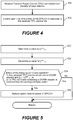
- FIG. 4 is a flowchart that illustrates operations and methods for controlling transmission power level of HS-DPCCH in accordance with some embodiments of the present invention.
- the UE 110 concurrently receives (block 400) TPC commands from the base stations 120a,120b.
- the concurrently received TPC commands are not necessarily simultaneously received or received during overlapping times, but may additionally or alternatively refer to a scenario when one of the TPC commands is received while the other TPC command is being considered by the UE 110 for use in controlling transmission power.
- the UE 110 controls (block 402) uplink transmit power of the HS-DPCCH in response to the received TPC commands.
- the TPC commands may be received (block 400) on a F-DPCH (fractional dedicated physical channel) from the first and second base stations 120a,120b.
- the first base station 120a may operate to provide a serving high-speed (HS) cell to the UE 110 by transmitting signals to the UE 110 on a HS-DPCCH (high-speed DPCCH).
- the UE 110 can control (block 402) uplink transmission power by the UE (110) of the HS-DPCCH by controlling uplink transmission power during transmission of channel quality reports through the HS-DPCCH to the first base station 120a responsive to the received TPC commands.
- the UE 110 determines (block 800) the parameter ( ⁇ HS ) responsive to a combination of the received TPC commands.
- the UE 110 controls (block 802) the uplink transmission power by the UE 110 of the HS-DPCCH responsive to a result of multiplying the parameter ⁇ HS and a transmission power level by the UE 110 of a dedicated physical control channel (DPCCH).
- DPCCH dedicated physical control channel
- the UE 110 adjusts the value of parameter ⁇ HS based on the received TPC commands.
- the UE 110 further determines values for parameters ⁇ HS nom and ⁇ HS max .
- the parameter ⁇ HS nom is determined (block 500) as a nominal value of parameter ⁇ HS , i.e. the value of parameter ⁇ HS at the start of the transmission.
- the parameter ⁇ HS max is determined (block 502) as a maximum value of parameter ⁇ HS .
- the UE 110 can be further configured to determine (block 504) that either of the following two conditions is satisfied: 1) any TPC command received from either of the first and second base stations 120a,120b contains a DOWN request (for the UE 110 to decrease transmission power of the HS-DPCCH) and that parameter ( ⁇ HS ) is less than the maximum value ⁇ HS max (i.e., ⁇ HS ⁇ ⁇ HS max ); or 2) the TPC command from the serving HS cell one of the base stations 120a, 120b contains a DOWN request (for the UE 110 to decrease transmission power of the DPCCH).
- the UE 110 responds to either one of the conditions being satisfied (block 504) by reducing (block 506) the uplink transmission power by the UE 110 of the DPCCH. Accordingly, when conflicting TPC commands are received from the base stations, the UE 110 will choose to decrease the uplink transmission power when the recited condition occurs.
- Figure 6 is a flowchart that illustrates operations and methods by the UE 110 for controlling values of the parameter ⁇ HS in accordance with some embodiments of the present invention.
- An initial value of the parameter ⁇ HS is determined (block 600).
- the initial value of parameter ⁇ HS may be computed in a conventional manner based on quantized amplitude ratios, which are translated from ⁇ ACK , ⁇ NACK , and ⁇ CQI signaling, such as described in 3GPP TS 25.213 V10.0.0 (2010-09), Sect. 4.3.1.2, and by translation of ⁇ ACK , ⁇ NACK , and ⁇ CQI signaling into parameter ⁇ values as described in 3GPP TS 25.214 V10.0.0 (2010-09), Sect. 5.1.2.5A.
- the UE 110 determines when the following condition is satisfied: 1) the UE reduced its uplink transmission power of the DPCCH power (block 506); and 2) the TPC command from the serving HS cell one of the base stations 120a, 120b contains an UP request (for the UE 110 to increase uplink transmission power of the DPCCH).
- the UE 110 responds by increasing (block 604) the parameter ⁇ HS value to increase (block 402) the uplink transmission power of the HS-DPCCH.
- the UE 110 increases the parameter ⁇ HS value in a step-wise manner using fixed step sizes, such as by increasing parameter ⁇ HS by 1 dB (or another defined step size) for each computation cycle when TPC commands are next received. Accordingly, the UE 110 may increase the parameter ⁇ HS by a fixed step size responsive to each instance of the TPC commands containing a request for the UE 110 to increase transmission power of the DPCCH.
- the UE 110 increases the parameter ⁇ HS value in a step-wise manner using step sizes that are determined based on a present value of parameter ⁇ HS .
- the UE 110 may include a table that defines values of parameter ⁇ HS and corresponding step-sizes. The UE 110 may then use a present value of parameter ⁇ HS as an index to look-up a step-size that is to be added to the present value of parameter ⁇ HS to generate the increased parameter ⁇ HS value.
- Control of the parameter ⁇ HS value is not limited to step-wise control, and may be controlled in another defined manner which may produce more continuous or other defined changes.
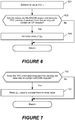
- FIG. 7 is a flowchart that illustrates further operations and methods by the UE 110 for controlling values of parameter ⁇ HS in accordance with some embodiments of the present invention.
- the UE 110 can be further configured to determine (block 700) when the TPC command received from the serving HS cell one of the base stations 120a,120b contains a DOWN request (for the UE 110 to decrease uplink transmission power of the DPCCH).
- the UE 110 responds by resetting (block 702) the parameter ⁇ HS value to a predefined nominal value.
- a UE may operate according to the operations of only one of Figures 4-8 , may operate according to operations of any two or more of Figures 4-8 , or may operate according to the operations of all of Figures 4-8 .
- the HS-DPCCH is controlled more robustly to ensure that signaling by the UE through the HS-DPCCH reaches the base station of the serving cell. Moreover, unnecessary interference between neighboring cells is avoided because the transmit power is only increased when required by the instantaneous channel conditions to the base stations involved in the soft handover.
- FIG. 9 is a block diagram of the UE 110 of the communications system of Figure 1 that is configured according to some embodiments of the present invention.
- the UE 110 includes a transceiver 902, a controller circuit 904, and a memory device(s) 906 containing functional modules 908.
- the UE 110 may further include other elements, such as a display 910, a user input interface 912, and a speaker 914.
- the transceiver 902 (e.g., WCDMA or other RF communication transceiver) is configured to communicate with the base stations 120a,120b of the system 100 over a wireless communication interface.
- the controller circuit 904 may include one or more data processing circuits, such as a general purpose and/or special purpose processor (e.g., microprocessor and/or digital signal processor).
- the controller circuit 904 is configured to execute computer program instructions from the functional modules 908 of the memory device(s) 906, described below as a computer readable medium, to perform at least some of the operations and methods described herein as being performed by a UE in accordance with one or more embodiments of the present invention.
- FIG 10 is a block diagram of a network node 1000 configured according to some embodiments of the present invention, and which may be included in the base stations 120a, 120b and/or the radio network controller 130 of the communications system of Figure 1 .
- the network node 1000 includes a transceiver 1001, a network interface(s) 1002, a controller circuit 1004, and a memory device(s) 1006 containing functional modules 1008.
- the transceiver 1001 (e.g., WCDMA or other RF communication transceiver) is configured to communicate with the UE 110 or another node of the system 100.
- the controller circuit 1004 may include one or more data processing circuits, such as a general purpose and/or special purpose processor (e.g., microprocessor and/or digital signal processor).
- the controller circuit 1004 is configured to execute computer program instructions from the functional modules 1008 of the memory device(s) 1006, described below as a computer readable medium, to perform at least some of the operations and methods described herein as being performed by a base station and/or RNC in accordance with one or more embodiments of the present invention.
- the network interface 1002 communicates with the RNC 130 (when located in a base station) or communicates with the base station and the core network 140 (when located in the RNC 130).
- node When a node is referred to as being “connected”, “coupled”, “responsive”, or variants thereof to another node, it can be directly connected, coupled, or responsive to the other node or intervening nodes may be present. In contrast, when an node is referred to as being “directly connected”, “directly coupled”, “directly responsive”, or variants thereof to another node, there are no intervening nodes present.
- Like numbers refer to like nodes throughout.
- “coupled”, “connected”, “responsive”, or variants thereof as used herein may include wirelessly coupled, connected, or responsive.
- the singular forms "a”, “an” and “the” are intended to include the plural forms as well, unless the context clearly indicates otherwise. Well-known functions or constructions may not be described in detail for brevity and/or clarity.
- the term “and/or”, abbreviated “/”, includes any and all combinations of one or more of the associated listed items.
- the terms “comprise”, “comprising”, “comprises”, “include”, “including”, “includes”, “have”, “has”, “having”, or variants thereof are open-ended, and include one or more stated features, integers, nodes, steps, components or functions but does not preclude the presence or addition of one or more other features, integers, nodes, steps, components, functions or groups thereof.
- the common abbreviation “e.g.” which derives from the Latin phrase “exempli gratia,” may be used to introduce or specify a general example or examples of a previously mentioned item, and is not intended to be limiting of such item.
- the common abbreviation “i.e.”, which derives from the Latin phrase “id est,” may be used to specify a particular item from a more general recitation.
- Example embodiments are described herein with reference to block diagrams and/or flowchart illustrations of computer-implemented methods, apparatus (systems and/or devices) and/or computer program products. It is understood that a block of the block diagrams and/or flowchart illustrations, and combinations of blocks in the block diagrams and/or flowchart illustrations, can be implemented by computer program instructions that are performed by one or more computer circuits.
- These computer program instructions may be provided to a processor circuit of a general purpose computer circuit, special purpose computer circuit, and/or other programmable data processing circuit to produce a machine, such that the instructions, which execute via the processor of the computer and/or other programmable data processing apparatus, transform and control transistors, values stored in memory locations, and other hardware components within such circuitry to implement the functions/acts specified in the block diagrams and/or flowchart block or blocks, and thereby create means (functionality) and/or structure for implementing the functions/acts specified in the block diagrams and/or flowchart block(s).
- These computer program instructions may also be stored in a tangible computer-readable medium that can direct a computer or other programmable data processing apparatus to function in a particular manner, such that the instructions stored in the computer-readable medium produce an article of manufacture including instructions which implement the functions/acts specified in the block diagrams and/or flowchart block or blocks.
- a tangible, non-transitory computer-readable medium may include an electronic, magnetic, optical, electromagnetic, or semiconductor data storage system, apparatus, or device. More specific examples of the computer-readable medium would include the following: a portable computer diskette, a random access memory (RAM) circuit, a read-only memory (ROM) circuit, an erasable programmable read-only memory (EPROM or Flash memory) circuit, a portable compact disc read-only memory (CD-ROM), and a portable digital video disc read-only memory (DVD/BlueRay).
- RAM random access memory
- ROM read-only memory
- EPROM or Flash memory erasable programmable read-only memory
- CD-ROM compact disc read-only memory
- DVD/BlueRay portable digital video disc read-only memory
- the computer program instructions may also be loaded onto a computer and/or other programmable data processing apparatus to cause a series of operational steps to be performed on the computer and/or other programmable apparatus to produce a computer-implemented process such that the instructions which execute on the computer or other programmable apparatus provide steps for implementing the functions/acts specified in the block diagrams and/or flowchart block or blocks.
- embodiments of the present invention may be embodied in hardware and/or in software (including firmware, resident software, micro-code, etc.) that runs on a processor such as a digital signal processor, which may collectively be referred to as "circuitry," "a module” or variants thereof.
Description
- The present invention relates to wireless communication systems and, more particularly, systems and methods that control uplink transmit power from user equipment nodes to network nodes.
- Wideband Code Division Multiple Access (WCDMA) is a mobile radio access network standard specified by a 3rd Generation Partnership Project (3GPP) and used in third generation wireless data/tele-communication systems.
- Soft handover is an important feature in all WCDMA systems. With soft handover, User Equipment Nodes (UEs) are effectively connected to several base stations at the same time. This improves reliability, since a UE that moves from one cell to another establishes a link to the new cell, before the link to the old cell is torn down. The way that soft handover is combined with transmit power control also limits uplink (UL) interference in soft handover scenarios.
- An
example WCDMA system 100 is shown inFigure 1 . Thesystem 100 includes a UE 110 that communicates with two base stations (also referred to as "Node Bs" and "network nodes" herein) 120a and 120b through a radio air interface. Thebase stations 120a-b are controlled by a radio network controller (RNC) 130 and connected to acore network 140. - Because WCDMA and High Speed Packet Access (HSPA) use common frequencies in all cells, a UE located at a border of one cell will cause uplink interference to neighboring cell(s). This interference can be particularly problematic because the UE located at the cell border (cell edge) will typically be transmitting near an upper range of its UL transmit power.
- Soft handover can be used to reduce uplink interference to the neighboring cell(s). UEs at the border between two cells are connected to both (several in the general case) cells. The UEs therefore transmit data to both cells and receive data from both cells.
- Transmit power control (or simply power control) is another important operation in WCDMA UL, since the channels within one cell are non-orthogonal: a transmission from one UE can strongly interfere with a transmission from another UE. In a WCDMA system, the uplink and downlink communications are power controlled. The UE signals to a base station how it shall regulate its downlink transmission power. In a similar way the base station signals to the UE how it shall regulate its uplink transmission power. A new transmit power control (TPC) command can be signaled every slot (e.g., 1500 TPC commands per second). Accordingly, at 1500 times per second, each UE can be commanded to either increase or decrease its transmit power by a predetermined step.
- The base station can control the UL packet error rate performance and UL interference by controlling the transmission power of the UE. As the UE increases its transmission power the experienced signal to interference ratio at the base station will in general increase. An increased signal to interference ratio will result in a lower packet error rate. In this way the base station can tune the uplink packet error rate.
- In soft handover, a UE is receiving power control commands from more than one cell. Based on the received signal, each cell commands the UE to either increase or decrease its transmit power. The UE thus receives several, possibly conflicting, transmit power commands. The power control commands from the cells are combined to decide if the UE should either increase or decrease its transmit power. To combine the power control commands, the UE follows an operational rule that if any power control commands contain a DOWN request, the UE reduces its transmit power.
- A UE transmits data and control information on physical channels that can include Dedicated Physical Control CHannel (DPCCH), Enhanced-DPCCH (E-DPCCH), Enhanced Dedicated Physical Data CHannel (E-DPDCH), and High-Speed DPCCH (HS-DPCCH). The DPCCH transmits pilot bits that are known by the base station and also
Layer 1 control information. The pilot bits are used as a reference by the base station to estimate the radio channel conditions (e.g. searcher, channel estimation, frequency offset estimation, and signal to interference ratio). The E-DPCCH transmits control information related to the enhanced dedicated physical data channel. The E-DPDCH transmits the data bits. -
Figure 2 illustrates graphs of transmission power levels and associated Transmission Power Control (TPC) commands that may be transmitted from a base station to a UE and, vice versa, from the UE to the base station to control the transmission power levels in the downlink and uplink directions. The base station measures the UL signal-to-interference ratio (SIR) on the DPCCH and compares it with a target value of the SIR. When the measured SIR is above the target SIR, the base station signals to the UE to decrease its transmission power. When the measured SIR is below the target SIR, the base station signals to the UE to increase its transmission power. For UEs capable of transmitting enhanced uplink, the UL-TPC (Up Link Transmission Power Control) commands are signaled to the UE on the downlink (DL) channel F-DPCH (Fractional Dedicated Physical CHannel). - In a similar manner the UE measures the quality of the F-DPCH that it receives from the base station. When the quality is sufficient, the UE signals to the base station that it can decrease the transmission power on the F-DPCH. When the quality is not sufficient, the UE signals to the base station to increase the transmission power on the F-DPCH. The DL-TPC commands are sent to the base station on the uplink channel DPCCH. The transmission power level of the E-DPCCH and the E-DPDCH may be controlled in response to a power offset relative to the transmission power level of the DPCCH.
- The TPC commands control the UE transmit power for DPCCH (PDPDCH). The UE controls the transmit power levels for the E-DPCCH (PE-DPCCH), the E-DPDCH (PE-DPDCH), and the HS-DPCCH (PHS-DPCCH) in response to a predefined power offset relative to the transmission power level of the DPCCH (PDPDCH), as follows:


-
Figure 3 illustrates a UE 110 that is connected to twobase stations base stations 120b is a low power node (e.g., pico node) having significantly lower transmission power than theother base station 120a (e.g., macro node). Cell selection is typically based on downlink received power, with the illustrated UE 110 typically connected to thebase station - This leads to a cell area surrounding the low
power base station 120b where the highpower base station 120a is selected, but where the path loss is lower toward the lowerpower base station 120b. In the uplink direction, where the transmit power is the same, it would be better for the UE 110 to be connected to the lowpower base station 120b. - If several base stations are received with similar transmit powers, the UE 110 enters soft handover. The above described operational rule for combining power control commands received from different base stations is intended to ensure that data reaches one of the cells involved in a soft handover. For the DPDCH, E-DPCCH and E-DPDCH, it is indeed enough that the transmission reaches one of the cells. However, the HS-DPCCH must reach one specific cell out of the cells involved in the soft handover, the so-called serving HS cell. The serving HS cell is the cell from which the high-speed downlink shared channel (HS-DSCH) is transmitted. The HS-DPCCH carried channel quality reports (CQIs) and ACK/NACKs that must reach the serving HS cell within a short delay (in the order of a few milliseconds).
- The
document EP 1 494 366 A1 discloses a method for controlling uplink transmit power of a HS-DPCCH when the UE is in soft handover. - With the current TPC command combining rule, the DPCCH transmit power may be reduced so that the HS-DPCCH is only received in the non-serving cell. To help alleviate the problem, the parameter βHS may be increased by a certain amount when the UE 110 enters soft handover. However, such an increase may be unnecessary in some cases, resulting in too high of an interference level (an unnecessary interference level).
- However, more importantly, in the context of the heterogeneous network of
Figure 3 , where theUE 110 communicates with the lowpower base station 120b and the highpower base station 120a, and theUE 110 is connected to the base station with the strongest received signal, the cell-border can be quite close to the lowpower base station 120b. In this case, the lowpower base station 120b will receive a correspondingly very strong signal from theUE 110, and it will subsequently order theUE 110 to reduce it transmit power quite significantly. As a result, the signal received at the highpower base station 120a (which may still be serving HE cell), will be quite weak, and using a fixed, large offset βHS will be insufficient for the highpower base station 120a to properly receive the signal from theUE 110. - Another situation where this problem is made worse is when Coordinated Multi-Point (CoMP) is deployed. When operating with CoMP, the base stations (e.g., 120a and 120b) involved in the soft handover will transmit different signals over the HS-DSCH, and the individual HS-DPCCH transmissions must reach both base stations (e.g., 120a and 120b).
- The approaches and presently recognized problems described above in this section could be pursued, but are not necessarily approaches and/or problems that have been previously conceived or pursued. Therefore, unless otherwise clearly indicated herein, the approaches and problems described above in this section are not prior art to claims in any application claiming priority from this application and are not admitted to be prior art by inclusion in this section.
- It may therefore be an object to address at least some of the above mentioned disadvantages and/or to improve performance in a wireless communication system.
- The invention is defined by a method according to
claim 1 and a user equipment according to claim 10. - Some embodiments of the present invention, for example, may provide improved power control during soft handover of a user equipment node (UE) between base stations.
- Some embodiments are directed to a method by a UE for controlling uplink transmission power during soft handover of the UE from a first base station to a second base station. A transmission power control (TPC) command is received from each of the first and second base stations during the soft handover. The UE controls uplink transmission power of a high-speed dedicated physical control channel responsive to the received TPC commands.
- In some situations, the UE can receive conflicting TPC commands from the base stations. However, by combine the TPC commands from the base stations, the uplink transmission power of the high-speed dedicated physical control channel can be more robustly controlled so it can be received by whichever of the base stations is operating as a high-speed serving cell for the UE while avoiding unnecessary interference to the other base station.
- In a further embodiment, the UE determines a parameter (βHS ) responsive to a combination of the received TPC commands, and controls the uplink transmission power of the high speed dedicated physical control channel responsive to a result of multiplying the parameter (βHS ) and a transmission power level by the UE of a dedicated physical control channel.
- In a further embodiment, the UE determines the parameter (βHS ) by determining a maximum value


- In a further embodiment, the first base station is a serving high-speed cell for the UE for communication of signals to the UE on a high-speed downlink shared channel. The UE determines when a condition occurs that the TPC command received from the first base station contains a request for the UE to decrease transmission power of the dedicated physical control channel. The UE responds to the determination that the condition occurred by reducing the uplink transmission power by the UE of the dedicated physical control channel. Accordingly, when conflicting TPC commands are received from the base stations, the UE will choose to decrease the uplink transmission power when the serving HS first base station requests the UE to decrease transmission power.
- In a further embodiment, the first base station is a serving high-speed cell for the UE for communication of signals to the UE on a high-speed downlink shared channel. The UE determines the parameter (βHS ) by determining when a condition occurs that the UE reduced the uplink transmission power of the dedicated physical control channel and the TPC command received from the first base station contains a request for the UE to increase transmission power of the dedicated physical control channel. The UE responds to the determination that the condition occurred by increasing the parameter (βHS ) to increase the uplink transmission power by the UE of the high-speed dedicated physical control channel.
- In a further embodiment, the first base station is a serving high-speed cell for the UE for communication of signals to the UE on a high-speed downlink shared channel. The UE determines the parameter (βHS ) by determining when a condition occurs that the TPC command received from the first base station contains a request for the UE to decrease transmission power of the dedicated physical control channel. The UE responds to the determination that the condition occurred by resetting the parameter (βHS ) to a predefined nominal value responsive to the determination that the condition occurred.
- In further embodiments, the UE may increase the parameter (βHS ) by a fixed step size responsive to the TPC commands containing a request for the UE to increase transmission power of the high-speed dedicated physical control channel. The UE may alternatively access a table that defines values of the parameter (βHS ) and corresponding step-sizes, using a present value of the parameter (βHS ) as an index to look-up one of the step-sizes, and add the looked-up one of the step-sizes to the present value of the parameter (βHS ) to generate a new value for the parameter (βHS ) used to control the uplink transmission power of the high-speed dedicated physical control channel.
- Other embodiments are directed to a corresponding UE that includes a transceiver and a controller circuit. The transceiver receives a TPC command from each of a first base station and a second base station during soft handover of the UE from the first base station to the second base station. The controller circuit controls uplink transmission power by the transceiver of a high-speed dedicated physical control channel responsive to the received TPC commands.
- Other methods, user equipment nodes, and systems according to embodiments of the invention will be or become apparent to one with skill in the art upon review of the following drawings and detailed description. It is intended that all such additional methods, user equipment nodes, and systems be included within this description, be within the scope of the present invention, and be protected by the accompanying claims. Moreover, it is intended that all embodiments disclosed herein can be implemented separately or combined in any way and/or combination.
- The accompanying drawings, which are included to provide a further understanding of the disclosure and are incorporated in and constitute a part of this application, illustrate certain non-limiting embodiment(s) of the invention. In the drawings:
-
Figure 1 is a block diagram of a communications system that regulates uplink and downlink transmission power between base stations and UEs; -
Figure 2 illustrates graphs of transmission power levels and associated TPC commands that may be transmitted from the base stations to the UE ofFigure 1 through dedicated physical channels and vice versa to control the transmission power levels in the downlink and uplink directions; -
Figure 3 is a block diagram of a UE connected to two base stations in a heterogeneous network; -
Figures 4-8 are flowcharts that illustrates operations and methods for controlling uplink transmission power in accordance with some embodiments of the present invention; -
Figure 9 is a block diagram of the UE of the communications system ofFigure 1 that is configured according to some embodiments of the present invention; and -
Figure 10 is a block diagram of a network node configured according to some embodiments of the present invention, and which may be included in the base stations and/or the radio network controller of the communications system ofFigure 1 . - In the following detailed description, numerous specific details are set forth in order to provide a thorough understanding of the invention. However, it will be understood by those skilled in the art that the present invention may be practiced without these specific details. In other instances, well-known methods, procedures, components and circuits have not been described in detail so as not to obscure the present invention.
- The following example embodiments provide a number of advantages and benefits relative to existing uplink transmission power control provided by UEs and base stations. It will be appreciated by those skilled in the art in view of the present description, however, that the invention is not limited to these embodiments which produce any or all of these advantages or benefits and that other advantages and benefits may be realized depending upon the particular implementation.
- Various embodiments of the present invention are directed to controlling uplink transmission power between base stations (e.g., a Node B) and a UE during soft handover. Although embodiments are disclosed in the context of a WCDMA 3GPP third generation communication system for ease of illustration and explanation only, the invention is not limited thereto. Instead embodiments of the invention may also be embodied in other types of base stations, UEs, and communication systems that control uplink transmission power. Moreover, although only a pair of base stations are shown in
Figure 1 , it is to be understood that the UE may communicate with any number of base stations during soft handover as controlled by predefined soft handover operations and methods. - With further reference to
Figure 1 , theUE 110 may be a mobile telephone ("cellular" telephone), a data terminal, and/or another processing device with wireless communication capability, such as, without limitation, a portable computer, a pocket computer, a hand-held computer, a laptop computer, an electronic book reader, and/or a video game console. - During soft handover, the
UE 110 communicates with the base stations (e.g., Node Bs) 120a and 120b, and dynamically controls its uplink transmission power in response to TPC commands received from thebase stations - Each
base station UE 110 and compares it with a target value of the SIR. When the measured SIR is above the target SIR, the base station sends a TPC command containing a DOWN request (instruction) to theUE 110 to request that theUE 110 decrease its uplink transmission power. When the measured SIR is below the target SIR, the base station sends a TPC command containing an UP request to theUE 110 to request that theUE 110 increase its uplink transmission power. When theUE 110 is capable of transmitting enhanced uplink, the UL-TPC commands are signaled to theUE 110 on the downlink channel F-DPCH (Fractional Dedicated Physical CHannel). - The TPC commands control the UE transmit power for DPCCH (PDPDCH). The
UE 110 controls the transmit power levels for the E-DPCCH (PE-DPCCH), the E-DPDCH (PE-DPDCH), and the HS-DPCCH (PHS-DPCCH) in response to a power offset relative to the transmission power level of the DPCCH (PDPDCH), as follows:


- Based on the received signal, each
base station UE 110 to either increase or decrease its uplink transmission power. TheUE 110 therefore concurrently receives several, possibly conflicting, transmit power commands. The transmit power commands from thebase stations UE 110 should either increase or decrease it uplink transmission power. - In accordance with various embodiments of the present invention, the
UE 110 is configured to combine the TPC commands from thebase stations base stations -
Figure 4 is a flowchart that illustrates operations and methods for controlling transmission power level of HS-DPCCH in accordance with some embodiments of the present invention. TheUE 110 concurrently receives (block 400) TPC commands from thebase stations UE 110 for use in controlling transmission power. TheUE 110 controls (block 402) uplink transmit power of the HS-DPCCH in response to the received TPC commands. - The TPC commands may be received (block 400) on a F-DPCH (fractional dedicated physical channel) from the first and
second base stations first base station 120a may operate to provide a serving high-speed (HS) cell to theUE 110 by transmitting signals to theUE 110 on a HS-DPCCH (high-speed DPCCH). TheUE 110 can control (block 402) uplink transmission power by the UE (110) of the HS-DPCCH by controlling uplink transmission power during transmission of channel quality reports through the HS-DPCCH to thefirst base station 120a responsive to the received TPC commands. - More particular operations and methods that may be performed by the
UE 110 to control (block 402) uplink transmit power of the HS-DPCCH are shown inFigure 8 . TheUE 110 determines (block 800) the parameter (βHS ) responsive to a combination of the received TPC commands. TheUE 110 controls (block 802) the uplink transmission power by theUE 110 of the HS-DPCCH responsive to a result of multiplying the parameter βHS and a transmission power level by theUE 110 of a dedicated physical control channel (DPCCH). - Further operations and methods that may be performed by the
UE 110 to control (block 802) uplink transmit power of the HS-DPCCH are shown inFigure 5 . TheUE 110 adjusts the value of parameter βHS based on the received TPC commands. To adjust parameter βHS, theUE 110 further determines values for parameters


- The
UE 110 can be further configured to determine (block 504) that either of the following two conditions is satisfied: 1) any TPC command received from either of the first andsecond base stations UE 110 to decrease transmission power of the HS-DPCCH) and that parameter (βHS ) is less than the maximum value

base stations UE 110 to decrease transmission power of the DPCCH). TheUE 110 responds to either one of the conditions being satisfied (block 504) by reducing (block 506) the uplink transmission power by theUE 110 of the DPCCH. Accordingly, when conflicting TPC commands are received from the base stations, theUE 110 will choose to decrease the uplink transmission power when the recited condition occurs. -
Figure 6 is a flowchart that illustrates operations and methods by theUE 110 for controlling values of the parameter βHS in accordance with some embodiments of the present invention. An initial value of the parameter βHS is determined (block 600). The initial value of parameter βHS may be computed in a conventional manner based on quantized amplitude ratios, which are translated from ΔACK, ΔNACK, and ΔCQI signaling, such as described in 3GPP TS 25.213 V10.0.0 (2010-09), Sect. 4.3.1.2, and by translation of ΔACK, ΔNACK, and ΔCQI signaling into parameter β values as described in 3GPP TS 25.214 V10.0.0 (2010-09), Sect. 5.1.2.5A. - In accordance with further embodiments, the
UE 110 determines when the following condition is satisfied: 1) the UE reduced its uplink transmission power of the DPCCH power (block 506); and 2) the TPC command from the serving HS cell one of thebase stations UE 110 to increase uplink transmission power of the DPCCH). TheUE 110 responds by increasing (block 604) the parameter βHS value to increase (block 402) the uplink transmission power of the HS-DPCCH. - In some embodiments, the
UE 110 increases the parameter βHS value in a step-wise manner using fixed step sizes, such as by increasing parameter βHS by 1 dB (or another defined step size) for each computation cycle when TPC commands are next received. Accordingly, theUE 110 may increase the parameter βHS by a fixed step size responsive to each instance of the TPC commands containing a request for theUE 110 to increase transmission power of the DPCCH. - In some other embodiments, the
UE 110 increases the parameter βHS value in a step-wise manner using step sizes that are determined based on a present value of parameter βHS. For example, theUE 110 may include a table that defines values of parameter βHS and corresponding step-sizes. TheUE 110 may then use a present value of parameter βHS as an index to look-up a step-size that is to be added to the present value of parameter βHS to generate the increased parameter βHS value. - Control of the parameter βHS value is not limited to step-wise control, and may be controlled in another defined manner which may produce more continuous or other defined changes.
-
Figure 7 is a flowchart that illustrates further operations and methods by theUE 110 for controlling values of parameter βHS in accordance with some embodiments of the present invention. TheUE 110 can be further configured to determine (block 700) when the TPC command received from the serving HS cell one of thebase stations UE 110 to decrease uplink transmission power of the DPCCH). TheUE 110 responds by resetting (block 702) the parameter βHS value to a predefined nominal value. - Although various operations and methods have been explained with separate reference to the flowcharts of
Figures 4-8 for ease of illustration and explanation, it is to be understood that these operations and methods may be combined in any manner. Thus, for example, a UE may operate according to the operations of only one ofFigures 4-8 , may operate according to operations of any two or more ofFigures 4-8 , or may operate according to the operations of all ofFigures 4-8 . - Operating in this manner, the HS-DPCCH is controlled more robustly to ensure that signaling by the UE through the HS-DPCCH reaches the base station of the serving cell. Moreover, unnecessary interference between neighboring cells is avoided because the transmit power is only increased when required by the instantaneous channel conditions to the base stations involved in the soft handover.
-
Figure 9 is a block diagram of theUE 110 of the communications system ofFigure 1 that is configured according to some embodiments of the present invention. TheUE 110 includes atransceiver 902, acontroller circuit 904, and a memory device(s) 906 containingfunctional modules 908. TheUE 110 may further include other elements, such as adisplay 910, a user input interface 912, and aspeaker 914. - The transceiver 902 (e.g., WCDMA or other RF communication transceiver) is configured to communicate with the
base stations system 100 over a wireless communication interface. Thecontroller circuit 904 may include one or more data processing circuits, such as a general purpose and/or special purpose processor (e.g., microprocessor and/or digital signal processor). Thecontroller circuit 904 is configured to execute computer program instructions from thefunctional modules 908 of the memory device(s) 906, described below as a computer readable medium, to perform at least some of the operations and methods described herein as being performed by a UE in accordance with one or more embodiments of the present invention. -
Figure 10 is a block diagram of anetwork node 1000 configured according to some embodiments of the present invention, and which may be included in thebase stations radio network controller 130 of the communications system ofFigure 1 . Thenetwork node 1000 includes atransceiver 1001, a network interface(s) 1002, acontroller circuit 1004, and a memory device(s) 1006 containingfunctional modules 1008. - The transceiver 1001 (e.g., WCDMA or other RF communication transceiver) is configured to communicate with the
UE 110 or another node of thesystem 100. Thecontroller circuit 1004 may include one or more data processing circuits, such as a general purpose and/or special purpose processor (e.g., microprocessor and/or digital signal processor). Thecontroller circuit 1004 is configured to execute computer program instructions from thefunctional modules 1008 of the memory device(s) 1006, described below as a computer readable medium, to perform at least some of the operations and methods described herein as being performed by a base station and/or RNC in accordance with one or more embodiments of the present invention. Thenetwork interface 1002 communicates with the RNC 130 (when located in a base station) or communicates with the base station and the core network 140 (when located in the RNC 130). - When a node is referred to as being "connected", "coupled", "responsive", or variants thereof to another node, it can be directly connected, coupled, or responsive to the other node or intervening nodes may be present. In contrast, when an node is referred to as being "directly connected", "directly coupled", "directly responsive", or variants thereof to another node, there are no intervening nodes present. Like numbers refer to like nodes throughout. Furthermore, "coupled", "connected", "responsive", or variants thereof as used herein may include wirelessly coupled, connected, or responsive. As used herein, the singular forms "a", "an" and "the" are intended to include the plural forms as well, unless the context clearly indicates otherwise. Well-known functions or constructions may not be described in detail for brevity and/or clarity. The term "and/or", abbreviated "/", includes any and all combinations of one or more of the associated listed items.
- As used herein, the terms "comprise", "comprising", "comprises", "include", "including", "includes", "have", "has", "having", or variants thereof are open-ended, and include one or more stated features, integers, nodes, steps, components or functions but does not preclude the presence or addition of one or more other features, integers, nodes, steps, components, functions or groups thereof. Furthermore, as used herein, the common abbreviation "e.g.", which derives from the Latin phrase "exempli gratia," may be used to introduce or specify a general example or examples of a previously mentioned item, and is not intended to be limiting of such item. The common abbreviation "i.e.", which derives from the Latin phrase "id est," may be used to specify a particular item from a more general recitation.
- Example embodiments are described herein with reference to block diagrams and/or flowchart illustrations of computer-implemented methods, apparatus (systems and/or devices) and/or computer program products. It is understood that a block of the block diagrams and/or flowchart illustrations, and combinations of blocks in the block diagrams and/or flowchart illustrations, can be implemented by computer program instructions that are performed by one or more computer circuits. These computer program instructions may be provided to a processor circuit of a general purpose computer circuit, special purpose computer circuit, and/or other programmable data processing circuit to produce a machine, such that the instructions, which execute via the processor of the computer and/or other programmable data processing apparatus, transform and control transistors, values stored in memory locations, and other hardware components within such circuitry to implement the functions/acts specified in the block diagrams and/or flowchart block or blocks, and thereby create means (functionality) and/or structure for implementing the functions/acts specified in the block diagrams and/or flowchart block(s).
- These computer program instructions may also be stored in a tangible computer-readable medium that can direct a computer or other programmable data processing apparatus to function in a particular manner, such that the instructions stored in the computer-readable medium produce an article of manufacture including instructions which implement the functions/acts specified in the block diagrams and/or flowchart block or blocks.
- A tangible, non-transitory computer-readable medium may include an electronic, magnetic, optical, electromagnetic, or semiconductor data storage system, apparatus, or device. More specific examples of the computer-readable medium would include the following: a portable computer diskette, a random access memory (RAM) circuit, a read-only memory (ROM) circuit, an erasable programmable read-only memory (EPROM or Flash memory) circuit, a portable compact disc read-only memory (CD-ROM), and a portable digital video disc read-only memory (DVD/BlueRay).
- The computer program instructions may also be loaded onto a computer and/or other programmable data processing apparatus to cause a series of operational steps to be performed on the computer and/or other programmable apparatus to produce a computer-implemented process such that the instructions which execute on the computer or other programmable apparatus provide steps for implementing the functions/acts specified in the block diagrams and/or flowchart block or blocks. Accordingly, embodiments of the present invention may be embodied in hardware and/or in software (including firmware, resident software, micro-code, etc.) that runs on a processor such as a digital signal processor, which may collectively be referred to as "circuitry," "a module" or variants thereof.
- It should also be noted that in some alternate implementations, the functions/acts noted in the blocks may occur out of the order noted in the flowcharts. For example, two blocks shown in succession may in fact be executed substantially concurrently or the blocks may sometimes be executed in the reverse order, depending upon the functionality/acts involved. Moreover, the functionality of a given block of the flowcharts and/or block diagrams may be separated into multiple blocks and/or the functionality of two or more blocks of the flowcharts and/or block diagrams may be at least partially integrated. Finally, other blocks may be added/inserted between the blocks that are illustrated. Moreover, although some of the diagrams include arrows on communication paths to show a primary direction of communication, it is to be understood that communication may occur in the opposite direction to the depicted arrows.
- Many different embodiments have been disclosed herein, in connection with the above description and the drawings. It will be understood that it would be unduly repetitious and obfuscating to literally describe and illustrate every combination and subcombination of these embodiments. Accordingly, the present specification, including the drawings, shall be construed to constitute a complete written description of various example combinations and subcombinations of embodiments and of the manner and process of making and using them, and shall support claims to any such combination or subcombination.
- Moreover, it is intended that all embodiments disclosed herein can be implemented separately or combined in any way and/or combination.
Claims (17)
- A method by a user equipment node, UE, (110) for controlling uplink transmission power during soft handover of the UE (110) from a first base station (120a) to a second base station (120b), the method comprising:receiving (400) a transmission power control, TPC, command from each of the first and second base stations (120a, 120b) during the soft handover; andcontrolling (402) uplink transmission power by the UE (110) of a high-speed dedicated physical control channel (202) responsive to the received TPC commands, characterized in that controlling (402) uplink transmission power by the UE (110) of the high speed dedicated physical control channel responsive to the received TPC commands comprises:determining (800) a parameter (βHS ) responsive to a combination of the received TPC commands; andcontrolling (802) the uplink transmission power by the UE (110) of the high speed dedicated physical control channel responsive to a result of multiplying the parameter (βHS ) and a transmission power level by the UE (110) of a dedicated physical control channel, wherein determining (800) the parameter (βHS ) comprises:determining (500) a predefined nominal value (
 determining (502) a maximum value
 determining (504) occurrence of a first condition when at least one of the TPC commands received from the first and second base stations (120a, 120b) contains a request for the UE (110) to decrease transmission power of the dedicated physical control channel (202) and the parameter (βHS ) is less than the maximum value
 reducing (506) the uplink transmission power by the UE (110) of the dedicated physical control channel (202), responsive to the determination (504) that the first condition occurred;determining (602) occurrence of a second condition when the UE reduced the uplink transmission power of the dedicated physical control channel (202) and the TPC command received from the first base station (120a) contains a request for the UE (110) to increase transmission power of the dedicated physical control channel (202);increasing (604) the parameter (βHS ) to increase (402) the uplink transmission power by the UE (110) of the high-speed dedicated physical control channel (202), responsive to the determination (602) that the second condition occurred;determining (700) occurrence of a third condition when the TPC command received from the first base station (120a) contains a request for the UE (110) to decrease transmission power of the dedicated physical control channel (202); andresetting (702) the parameter (βHS ) to the predefined nominal value (
- The method of Claim 1, wherein:
receiving (400) comprises receiving the TPC commands on a fractional dedicated physical channel (200) from the first and second base stations (120a, 120b). - The method of any of Claims 1-2,
further comprising
receiving signals by the UE (110) on a high-speed downlink shared channel from the first base station (120a), and
wherein controlling (402) uplink transmission power by the UE (110) of the high-speed dedicated physical control channel comprises controlling uplink transmission power during transmission of channel quality reports through the high-speed dedicated physical control channel to the first base station (120a) responsive to the received TPC commands. - The method of Claim 1, wherein controlling (802) the uplink transmission power by the UE (110) of the dedicated physical control channel comprises:determining (504) when a condition occurs that at least one of the TPC commands received from the first and second base stations (120a, 120b) contains a request for the UE (110) to decrease transmission power of the dedicated physical control channel (202) and the parameter (βHS ) is less than the maximum value
 reducing (506) the uplink transmission power by the UE (110) of the dedicated physical control channel (202) responsive to the determination (504) that the condition occurred.
 - The method of any of Claims 1, 4,
wherein controlling (802) the uplink transmission power by the UE (110) of the dedicated physical control channel comprises:determining (504) when a condition occurs that the TPC command received from the first base station (120a) contains a request for the UE (110) to decrease transmission power of the dedicated physical control channel (202); andreducing (506) the uplink transmission power by the UE (110) of the dedicated physical control channel (202), responsive to the determination (504) that the condition occurred. - The method of any of Claims 1, 4, 5,
wherein determining (800) the parameter (βHS ) comprises:determining (602) when a condition occurs that the UE reduced the uplink transmission power of the dedicated physical control channel (202) and the TPC command received from the first base station (120a) contains a request for the UE (110) to increase transmission power of the dedicated physical control channel (202); andincreasing (604) the parameter (βHS ) to increase (402) the uplink transmission power by the UE (110) of the high-speed dedicated physical control channel (202), responsive to the determination (602) that the condition occurred. - The method of Claims 6, wherein determining (800) the parameter (βHS ) comprises increasing the parameter (βHS ) by a fixed step size responsive to the TPC commands containing a request for the UE (110) to increase transmission power of the high-speed dedicated physical control channel (202).
- The method of Claim 6, wherein determining (800) the parameter (βHS ) comprises:accessing a table that defines values of the parameter (βHS ) and corresponding step-sizes, by using a present value of the parameter (βHS ) as an index to look-up one of the step-sizes; andadding the looked-up one of the step-sizes to the present value of the parameter (βHS ) to generate a new value for the parameter (βHS ) used to control (402) the uplink transmission power by the UE (110) of the high-speed dedicated physical control channel (202).
- The method of Claim 1,
wherein determining (800) the parameter (βHS ) comprises:determining (700) when a condition occurs that the TPC command received from the first base station (120a) contains a request for the UE (110) to decrease transmission power of the dedicated physical control channel (202); andresetting (702) the parameter (βHS ) to the predefined nominal value responsive to the determination (700) that the condition occurred. - A user equipment node, UE, (110) comprising:a transceiver (902) that receives (400) a transmission power control, TPC, command from each of a first base station (120a) and a second base station (120b) during soft handover of the UE (110) from the first base station (120a) to the second base station (120b); anda controller circuit (904) that controls (402) uplink transmission power by the transceiver (902) of a high-speed dedicated physical control channel (202) responsive to the received TPC commands, characterized in that the controller circuit (904) is adapted to determine (800) a parameter (βHS ) responsive to a combination of the received TPC commands, and adapted to control the uplink transmission power by the transceiver (902) of the high-speed dedicated physical control channel (202) responsive to a result of multiplying the parameter (βHS ) and a transmission power level by the transceiver (902) of a dedicated physical control channel,wherein the controller circuit (904) is adapted to determine (800) the parameter (βHS ) by:determining (500) a predefined nominal value (
 determining (502) a maximum value
 determining (504) occurrence of a first condition when at least one of the TPC commands received from the first and second base stations (120a, 120b) contains a request for the UE (110) to decrease transmission power of the dedicated physical control channel (202) and the parameter (βHS ) is less than the maximum value
 reducing (506) the uplink transmission power by the UE (110) of the dedicated physical control channel (202), responsive to the determination (504) that the first condition occurred;determining (602) occurrence of a second condition when the UE reduced the uplink transmission power of the dedicated physical control channel (202) and the TPC command received from the first base station (120a) contains a request for the UE (110) to increase transmission power of the dedicated physical control channel (202);increasing (604) the parameter (βHS ) to increase (402) the uplink transmission power by the UE (110) of the high-speed dedicated physical control channel (202), responsive to the determination (602) that the second condition occurred;determining (700) occurrence of a third condition when the TPC command received from the first base station (120a) contains a request for the UE (110) to decrease transmission power of the dedicated physical control channel (202); andresetting (702) the parameter (βHS ) to the predefined nominal value (
- The UE (110) of Claim 10, wherein:the transceiver (902) is adapted to receive signals on a high-speed downlink shared channel from the first base station (120a) andthe controller circuit (904) is adapted to control (402) uplink transmission power by the transceiver (902) of the high-speed dedicated physical control channel (202) during transmission of channel quality reports through the high-speed dedicated physical control channel (202) to the first base station (120a) responsive to the received TPC commands.
- The UE (110) of Claim 10, wherein:
the controller circuit (904) is adapted to determine (504) when a condition occurs that at least one of the TPC commands received from the first and second base stations (120a, 120b) contains a request for the UE (110) to decrease transmission power of the dedicated physical control channel (202) and the parameter (βHS ) is less than the maximum value
- The UE (110) of any of Claims 10-12,
the controller circuit (904) is adapted to determine (504) when a condition occurs that the TPC command received from the first base station (120a) contains a request for the UE (110) to decrease transmission power of the dedicated physical control channel (202), and adapted to reduce (506) the uplink transmission power of the transceiver (902) of the dedicated physical control channel (202), responsive to the determination (504) that the condition occurred. - The UE (110) of any of Claims 10-13,
wherein the controller circuit (904) is adapted to determine (800) the parameter (βHS ) by:determining (602) when a condition occurs that the UE reduced the uplink transmission power of the dedicated physical control channel (202) and the TPC command received from the first base station (120a) contains a request for the UE (110) to increase transmission power of the dedicated physical control channel (202); andincreasing (604) the parameter (βHS ) to increase (402) the uplink transmission power of the transceiver (902) of the high-speed dedicated physical control channel (202), responsive to the determination (602) that the condition occurred. - The UE (110) of Claim 14, wherein:
the controller circuit (904) is adapted to increase the parameter (βHS ) by a fixed step size responsive to the TPC commands containing a request for the UE (110) to increase transmission power of the high-speed dedicated physical control channel (202) by the transceiver (902). - The UE (110) of Claim 14, wherein the controller circuit (904) is adapted to determine (800) the parameter (βHS ) by:accessing a table that defines values of the parameter (βHS ) and corresponding step-sizes, by using a present value of the parameter (βHS ) as an index to look-up one of the step-sizes; andadding the looked-up one of the step-sizes to the present value of the parameter (βHS ) to generate a new value for the parameter (βHS ) used to control (402) the uplink transmission power of the transceiver (902) of the high-speed dedicated physical control channel (202).
- The UE (110) of Claim 10,
wherein the controller circuit (904) is adapted to determine (800) the parameter (βHS ) by:determining (700) when a condition occurs that the TPC command received from the first base station (120a) contains a request for the UE (110) to decrease transmission power of the dedicated physical control channel (202); andresetting (702) the parameter (βHS ) to the predefined nominal value responsive to the determination (700) that the condition occurred.
Applications Claiming Priority (2)
| Application Number | Priority Date | Filing Date | Title |
|---|---|---|---|
| US201161543205P | 2011-10-04 | 2011-10-04 | |
| PCT/SE2012/050761 WO2013051987A1 (en) | 2011-10-04 | 2012-07-02 | Controlling uplink transmit power responsive to combination of received power control commands during soft handover in a communicaton system |
Publications (2)
| Publication Number | Publication Date |
|---|---|
| EP2749094A1 EP2749094A1 (en) | 2014-07-02 |
| EP2749094B1 true EP2749094B1 (en) | 2018-06-06 |
Family
ID=46634491
Family Applications (1)
| Application Number | Title | Priority Date | Filing Date |
|---|---|---|---|
| EP12743789.5A Not-in-force EP2749094B1 (en) | 2011-10-04 | 2012-07-02 | Controlling uplink transmit power responsive to combination of received power control commands during soft handover in a communicaton system |
Country Status (4)
| Country | Link |
|---|---|
| US (1) | US9008042B2 (en) |
| EP (1) | EP2749094B1 (en) |
| IN (1) | IN2014KN00950A (en) |
| WO (1) | WO2013051987A1 (en) |
Families Citing this family (9)
| Publication number | Priority date | Publication date | Assignee | Title |
|---|---|---|---|---|
| EP2911442A4 (en) * | 2012-11-09 | 2015-12-23 | Huawei Tech Co Ltd | Method for uplink softer handover, ue and base station |
| WO2014166107A1 (en) * | 2013-04-12 | 2014-10-16 | 华为技术有限公司 | Control method and user equipment for power configuration in heterogeneous network |
| JP5964792B2 (en) * | 2013-08-30 | 2016-08-03 | 京セラ株式会社 | User terminal, communication control device, and processor |
| JP2015050575A (en) * | 2013-08-30 | 2015-03-16 | 株式会社Nttドコモ | Radio base station, user terminal, and transmission power control method |
| US9706421B2 (en) | 2013-12-06 | 2017-07-11 | Qualcomm Incorporated | Apparatus and method for sire bias compensation |
| EP3085171B1 (en) * | 2013-12-20 | 2021-03-24 | Telefonaktiebolaget LM Ericsson (publ) | Method and means for maintaining uplink time alignment |
| JP6521577B2 (en) * | 2014-06-16 | 2019-05-29 | キヤノン株式会社 | Image forming apparatus and control method thereof |
| WO2016050316A1 (en) * | 2014-10-03 | 2016-04-07 | Telefonaktiebolaget Lm Ericsson (Publ) | Methods and network nodes in a wireless communication network for handling of uplink signals sent by a user equipment |
| US20190357150A1 (en) * | 2018-05-17 | 2019-11-21 | Qualcomm Incorporated | Transmission power configuration |
Family Cites Families (9)
| Publication number | Priority date | Publication date | Assignee | Title |
|---|---|---|---|---|
| US6334047B1 (en) * | 1999-04-09 | 2001-12-25 | Telefonaktiebolaget Lm Ericsson (Publ) | Adaptive power control in a mobile radio communications system |
| CN1192530C (en) | 2002-04-08 | 2005-03-09 | 华为技术有限公司 | Method for controlling upline control channel power in soft switching of high speed data packet insertion system |
| GB2415324B (en) * | 2004-06-16 | 2006-06-28 | Siemens Ag | A method of controlling uplink power level |
| WO2006071162A1 (en) | 2004-12-30 | 2006-07-06 | Telefonaktiebolaget Lm Ericsson (Publ) | Method and system of wireless communications |
| US20080200202A1 (en) * | 2007-02-13 | 2008-08-21 | Qualcomm Incorporated | Power control with link imbalance on downlink and uplink |
| GB2452288A (en) * | 2007-08-29 | 2009-03-04 | Nokia Siemens Networks Oy | Timing of wireless transmissions using a common channel |
| EP2218191A4 (en) * | 2007-12-06 | 2015-05-13 | Ericsson Telefon Ab L M | Method and arrangement for power control during soft handover |
| US20120008510A1 (en) * | 2010-01-07 | 2012-01-12 | Interdigital Patent Holdings, Inc. | Method and Apparatus for Performing Uplink Antenna Transmit Diversity |
| WO2012050506A1 (en) * | 2010-10-12 | 2012-04-19 | Telefonaktiebolaget L M Ericsson (Publ) | Uplink power control |
-
2012
- 2012-07-02 US US13/581,681 patent/US9008042B2/en active Active
- 2012-07-02 WO PCT/SE2012/050761 patent/WO2013051987A1/en active Application Filing
- 2012-07-02 EP EP12743789.5A patent/EP2749094B1/en not_active Not-in-force
- 2012-07-02 IN IN950KON2014 patent/IN2014KN00950A/en unknown
Non-Patent Citations (1)
| Title |
|---|
| None * |
Also Published As
| Publication number | Publication date |
|---|---|
| US20140003388A1 (en) | 2014-01-02 |
| US9008042B2 (en) | 2015-04-14 |
| WO2013051987A1 (en) | 2013-04-11 |
| IN2014KN00950A (en) | 2015-10-09 |
| EP2749094A1 (en) | 2014-07-02 |
Similar Documents
| Publication | Publication Date | Title |
|---|---|---|
| EP2749094B1 (en) | Controlling uplink transmit power responsive to combination of received power control commands during soft handover in a communicaton system | |
| US20200275381A1 (en) | Uplink power control method and apparatus | |
| EP2730135B1 (en) | Controlling uplink transmission power during asynchronous switching of control states by user equipment | |
| US11653313B2 (en) | Power control method and user equipment in device to device communication in serving cell | |
| US9930622B2 (en) | Power control of uplink control channels in heterogeneous networks | |
| JP5646611B2 (en) | Transmission power control of channels transmitted in different frequency regions | |
| WO2014067092A1 (en) | Power adjustment method and device | |
| WO2012056859A1 (en) | Mobile communication system, base station, and transmission power control method | |
| US9961644B2 (en) | Fast fading power restriction | |
| US20160157237A1 (en) | Method and Device of Performing Multi-Radio Access Bearer Power Scaling | |
| US20140099988A1 (en) | Method and apparatus for controlling transmission power of multiple uplink channels in the same frequency band | |
| US9392559B2 (en) | Uplink interference suppression in a wireless communication network | |
| US20160255560A1 (en) | Providing Wireless Terminal Uplink Data Rate Offsets | |
| EP2946616B1 (en) | Method and device of performing multi-radio access bearer power scaling | |
| EP3060015B1 (en) | Method and device for controlling downlink power | |
| JP5423364B2 (en) | Radio base station, transmission power control method and program |
Legal Events
| Date | Code | Title | Description |
|---|---|---|---|
| PUAI | Public reference made under article 153(3) epc to a published international application that has entered the european phase |
Free format text: ORIGINAL CODE: 0009012 |
|
| 17P | Request for examination filed |
Effective date: 20140306 |
|
| AK | Designated contracting states |
Kind code of ref document: A1 Designated state(s): AL AT BE BG CH CY CZ DE DK EE ES FI FR GB GR HR HU IE IS IT LI LT LU LV MC MK MT NL NO PL PT RO RS SE SI SK SM TR |
|
| DAX | Request for extension of the european patent (deleted) | ||
| GRAP | Despatch of communication of intention to grant a patent |
Free format text: ORIGINAL CODE: EPIDOSNIGR1 |
|
| RIC1 | Information provided on ipc code assigned before grant |
Ipc: H04W 52/32 20090101ALN20180201BHEP Ipc: H04W 52/24 20090101ALN20180201BHEP Ipc: H04W 52/40 20090101AFI20180201BHEP Ipc: H04W 52/14 20090101ALN20180201BHEP Ipc: H04W 52/28 20090101ALI20180201BHEP Ipc: H04W 52/16 20090101ALN20180201BHEP |
|
| STAA | Information on the status of an ep patent application or granted ep patent |
Free format text: STATUS: GRANT OF PATENT IS INTENDED |
|
| INTG | Intention to grant announced |
Effective date: 20180308 |
|
| GRAS | Grant fee paid |
Free format text: ORIGINAL CODE: EPIDOSNIGR3 |
|
| GRAA | (expected) grant |
Free format text: ORIGINAL CODE: 0009210 |
|
| STAA | Information on the status of an ep patent application or granted ep patent |
Free format text: STATUS: THE PATENT HAS BEEN GRANTED |
|
| AK | Designated contracting states |
Kind code of ref document: B1 Designated state(s): AL AT BE BG CH CY CZ DE DK EE ES FI FR GB GR HR HU IE IS IT LI LT LU LV MC MK MT NL NO PL PT RO RS SE SI SK SM TR |
|
| REG | Reference to a national code |
Ref country code: GB Ref legal event code: FG4D |
|
| REG | Reference to a national code |
Ref country code: CH Ref legal event code: EP Ref country code: AT Ref legal event code: REF Ref document number: 1007405 Country of ref document: AT Kind code of ref document: T Effective date: 20180615 |
|
| REG | Reference to a national code |
Ref country code: IE Ref legal event code: FG4D |
|
| REG | Reference to a national code |
Ref country code: DE Ref legal event code: R096 Ref document number: 602012047169 Country of ref document: DE |
|
| REG | Reference to a national code |
Ref country code: NL Ref legal event code: MP Effective date: 20180606 |
|
| REG | Reference to a national code |
Ref country code: LT Ref legal event code: MG4D |
|
| PG25 | Lapsed in a contracting state [announced via postgrant information from national office to epo] |
Ref country code: FI Free format text: LAPSE BECAUSE OF FAILURE TO SUBMIT A TRANSLATION OF THE DESCRIPTION OR TO PAY THE FEE WITHIN THE PRESCRIBED TIME-LIMIT Effective date: 20180606 Ref country code: BG Free format text: LAPSE BECAUSE OF FAILURE TO SUBMIT A TRANSLATION OF THE DESCRIPTION OR TO PAY THE FEE WITHIN THE PRESCRIBED TIME-LIMIT Effective date: 20180906 Ref country code: NO Free format text: LAPSE BECAUSE OF FAILURE TO SUBMIT A TRANSLATION OF THE DESCRIPTION OR TO PAY THE FEE WITHIN THE PRESCRIBED TIME-LIMIT Effective date: 20180906 Ref country code: SE Free format text: LAPSE BECAUSE OF FAILURE TO SUBMIT A TRANSLATION OF THE DESCRIPTION OR TO PAY THE FEE WITHIN THE PRESCRIBED TIME-LIMIT Effective date: 20180606 Ref country code: ES Free format text: LAPSE BECAUSE OF FAILURE TO SUBMIT A TRANSLATION OF THE DESCRIPTION OR TO PAY THE FEE WITHIN THE PRESCRIBED TIME-LIMIT Effective date: 20180606 Ref country code: LT Free format text: LAPSE BECAUSE OF FAILURE TO SUBMIT A TRANSLATION OF THE DESCRIPTION OR TO PAY THE FEE WITHIN THE PRESCRIBED TIME-LIMIT Effective date: 20180606 Ref country code: CY Free format text: LAPSE BECAUSE OF FAILURE TO SUBMIT A TRANSLATION OF THE DESCRIPTION OR TO PAY THE FEE WITHIN THE PRESCRIBED TIME-LIMIT Effective date: 20180606 |
|
| PG25 | Lapsed in a contracting state [announced via postgrant information from national office to epo] |
Ref country code: HR Free format text: LAPSE BECAUSE OF FAILURE TO SUBMIT A TRANSLATION OF THE DESCRIPTION OR TO PAY THE FEE WITHIN THE PRESCRIBED TIME-LIMIT Effective date: 20180606 Ref country code: RS Free format text: LAPSE BECAUSE OF FAILURE TO SUBMIT A TRANSLATION OF THE DESCRIPTION OR TO PAY THE FEE WITHIN THE PRESCRIBED TIME-LIMIT Effective date: 20180606 Ref country code: GR Free format text: LAPSE BECAUSE OF FAILURE TO SUBMIT A TRANSLATION OF THE DESCRIPTION OR TO PAY THE FEE WITHIN THE PRESCRIBED TIME-LIMIT Effective date: 20180907 Ref country code: LV Free format text: LAPSE BECAUSE OF FAILURE TO SUBMIT A TRANSLATION OF THE DESCRIPTION OR TO PAY THE FEE WITHIN THE PRESCRIBED TIME-LIMIT Effective date: 20180606 |
|
| REG | Reference to a national code |
Ref country code: AT Ref legal event code: MK05 Ref document number: 1007405 Country of ref document: AT Kind code of ref document: T Effective date: 20180606 |
|
| PG25 | Lapsed in a contracting state [announced via postgrant information from national office to epo] |
Ref country code: NL Free format text: LAPSE BECAUSE OF FAILURE TO SUBMIT A TRANSLATION OF THE DESCRIPTION OR TO PAY THE FEE WITHIN THE PRESCRIBED TIME-LIMIT Effective date: 20180606 |
|
| PG25 | Lapsed in a contracting state [announced via postgrant information from national office to epo] |
Ref country code: EE Free format text: LAPSE BECAUSE OF FAILURE TO SUBMIT A TRANSLATION OF THE DESCRIPTION OR TO PAY THE FEE WITHIN THE PRESCRIBED TIME-LIMIT Effective date: 20180606 Ref country code: SK Free format text: LAPSE BECAUSE OF FAILURE TO SUBMIT A TRANSLATION OF THE DESCRIPTION OR TO PAY THE FEE WITHIN THE PRESCRIBED TIME-LIMIT Effective date: 20180606 Ref country code: AT Free format text: LAPSE BECAUSE OF FAILURE TO SUBMIT A TRANSLATION OF THE DESCRIPTION OR TO PAY THE FEE WITHIN THE PRESCRIBED TIME-LIMIT Effective date: 20180606 Ref country code: IS Free format text: LAPSE BECAUSE OF FAILURE TO SUBMIT A TRANSLATION OF THE DESCRIPTION OR TO PAY THE FEE WITHIN THE PRESCRIBED TIME-LIMIT Effective date: 20181006 Ref country code: CZ Free format text: LAPSE BECAUSE OF FAILURE TO SUBMIT A TRANSLATION OF THE DESCRIPTION OR TO PAY THE FEE WITHIN THE PRESCRIBED TIME-LIMIT Effective date: 20180606 Ref country code: RO Free format text: LAPSE BECAUSE OF FAILURE TO SUBMIT A TRANSLATION OF THE DESCRIPTION OR TO PAY THE FEE WITHIN THE PRESCRIBED TIME-LIMIT Effective date: 20180606 Ref country code: PL Free format text: LAPSE BECAUSE OF FAILURE TO SUBMIT A TRANSLATION OF THE DESCRIPTION OR TO PAY THE FEE WITHIN THE PRESCRIBED TIME-LIMIT Effective date: 20180606 |
|
| PG25 | Lapsed in a contracting state [announced via postgrant information from national office to epo] |
Ref country code: SM Free format text: LAPSE BECAUSE OF FAILURE TO SUBMIT A TRANSLATION OF THE DESCRIPTION OR TO PAY THE FEE WITHIN THE PRESCRIBED TIME-LIMIT Effective date: 20180606 Ref country code: IT Free format text: LAPSE BECAUSE OF FAILURE TO SUBMIT A TRANSLATION OF THE DESCRIPTION OR TO PAY THE FEE WITHIN THE PRESCRIBED TIME-LIMIT Effective date: 20180606 |
|
| REG | Reference to a national code |
Ref country code: CH Ref legal event code: PL |
|
| REG | Reference to a national code |
Ref country code: DE Ref legal event code: R097 Ref document number: 602012047169 Country of ref document: DE |
|
| PG25 | Lapsed in a contracting state [announced via postgrant information from national office to epo] |
Ref country code: LU Free format text: LAPSE BECAUSE OF NON-PAYMENT OF DUE FEES Effective date: 20180702 Ref country code: MC Free format text: LAPSE BECAUSE OF FAILURE TO SUBMIT A TRANSLATION OF THE DESCRIPTION OR TO PAY THE FEE WITHIN THE PRESCRIBED TIME-LIMIT Effective date: 20180606 |
|
| REG | Reference to a national code |
Ref country code: BE Ref legal event code: MM Effective date: 20180731 |
|
| PLBE | No opposition filed within time limit |
Free format text: ORIGINAL CODE: 0009261 |
|
| STAA | Information on the status of an ep patent application or granted ep patent |
Free format text: STATUS: NO OPPOSITION FILED WITHIN TIME LIMIT |
|
| REG | Reference to a national code |
Ref country code: IE Ref legal event code: MM4A |
|
| PG25 | Lapsed in a contracting state [announced via postgrant information from national office to epo] |
Ref country code: LI Free format text: LAPSE BECAUSE OF NON-PAYMENT OF DUE FEES Effective date: 20180731 Ref country code: CH Free format text: LAPSE BECAUSE OF NON-PAYMENT OF DUE FEES Effective date: 20180731 Ref country code: IE Free format text: LAPSE BECAUSE OF NON-PAYMENT OF DUE FEES Effective date: 20180702 |
|
| 26N | No opposition filed |
Effective date: 20190307 |
|
| PG25 | Lapsed in a contracting state [announced via postgrant information from national office to epo] |
Ref country code: BE Free format text: LAPSE BECAUSE OF NON-PAYMENT OF DUE FEES Effective date: 20180731 Ref country code: DK Free format text: LAPSE BECAUSE OF FAILURE TO SUBMIT A TRANSLATION OF THE DESCRIPTION OR TO PAY THE FEE WITHIN THE PRESCRIBED TIME-LIMIT Effective date: 20180606 Ref country code: SI Free format text: LAPSE BECAUSE OF FAILURE TO SUBMIT A TRANSLATION OF THE DESCRIPTION OR TO PAY THE FEE WITHIN THE PRESCRIBED TIME-LIMIT Effective date: 20180606 |
|
| PG25 | Lapsed in a contracting state [announced via postgrant information from national office to epo] |
Ref country code: FR Free format text: LAPSE BECAUSE OF NON-PAYMENT OF DUE FEES Effective date: 20180806 |
|
| PG25 | Lapsed in a contracting state [announced via postgrant information from national office to epo] |
Ref country code: AL Free format text: LAPSE BECAUSE OF FAILURE TO SUBMIT A TRANSLATION OF THE DESCRIPTION OR TO PAY THE FEE WITHIN THE PRESCRIBED TIME-LIMIT Effective date: 20180606 |
|
| PG25 | Lapsed in a contracting state [announced via postgrant information from national office to epo] |
Ref country code: MT Free format text: LAPSE BECAUSE OF NON-PAYMENT OF DUE FEES Effective date: 20180702 |
|
| PG25 | Lapsed in a contracting state [announced via postgrant information from national office to epo] |
Ref country code: TR Free format text: LAPSE BECAUSE OF FAILURE TO SUBMIT A TRANSLATION OF THE DESCRIPTION OR TO PAY THE FEE WITHIN THE PRESCRIBED TIME-LIMIT Effective date: 20180606 |
|
| PG25 | Lapsed in a contracting state [announced via postgrant information from national office to epo] |
Ref country code: PT Free format text: LAPSE BECAUSE OF FAILURE TO SUBMIT A TRANSLATION OF THE DESCRIPTION OR TO PAY THE FEE WITHIN THE PRESCRIBED TIME-LIMIT Effective date: 20180606 Ref country code: HU Free format text: LAPSE BECAUSE OF FAILURE TO SUBMIT A TRANSLATION OF THE DESCRIPTION OR TO PAY THE FEE WITHIN THE PRESCRIBED TIME-LIMIT; INVALID AB INITIO Effective date: 20120702 |
|
| PG25 | Lapsed in a contracting state [announced via postgrant information from national office to epo] |
Ref country code: MK Free format text: LAPSE BECAUSE OF NON-PAYMENT OF DUE FEES Effective date: 20180606 |
|
| PGFP | Annual fee paid to national office [announced via postgrant information from national office to epo] |
Ref country code: GB Payment date: 20220727 Year of fee payment: 11 Ref country code: DE Payment date: 20220629 Year of fee payment: 11 |
|
| REG | Reference to a national code |
Ref country code: DE Ref legal event code: R119 Ref document number: 602012047169 Country of ref document: DE |
|
| GBPC | Gb: european patent ceased through non-payment of renewal fee |
Effective date: 20230702 |