EP3085073B1 - Objekterkennungsvorrichtung, system zur steuerung einer vorrichtung mit einem beweglichen körper und programm dafür - Google Patents
Objekterkennungsvorrichtung, system zur steuerung einer vorrichtung mit einem beweglichen körper und programm dafür Download PDFInfo
- Publication number
- EP3085073B1 EP3085073B1 EP14870904.1A EP14870904A EP3085073B1 EP 3085073 B1 EP3085073 B1 EP 3085073B1 EP 14870904 A EP14870904 A EP 14870904A EP 3085073 B1 EP3085073 B1 EP 3085073B1
- Authority
- EP
- European Patent Office
- Prior art keywords
- light
- image
- imaging
- detection
- area
- Prior art date
- Legal status (The legal status is an assumption and is not a legal conclusion. Google has not performed a legal analysis and makes no representation as to the accuracy of the status listed.)
- Active
Links
- 238000001514 detection method Methods 0.000 title claims description 431
- 238000003384 imaging method Methods 0.000 claims description 448
- 238000000034 method Methods 0.000 claims description 60
- 238000005286 illumination Methods 0.000 claims description 48
- 230000008569 process Effects 0.000 claims description 41
- 230000008859 change Effects 0.000 claims description 15
- 238000012544 monitoring process Methods 0.000 claims 7
- 230000003252 repetitive effect Effects 0.000 claims 2
- 230000010287 polarization Effects 0.000 description 287
- 238000012545 processing Methods 0.000 description 157
- 230000003595 spectral effect Effects 0.000 description 150
- 230000003287 optical effect Effects 0.000 description 102
- 238000010586 diagram Methods 0.000 description 70
- 230000005540 biological transmission Effects 0.000 description 49
- 238000009826 distribution Methods 0.000 description 33
- 239000010408 film Substances 0.000 description 33
- 229910052751 metal Inorganic materials 0.000 description 26
- 239000002184 metal Substances 0.000 description 26
- 239000000945 filler Substances 0.000 description 22
- 239000000758 substrate Substances 0.000 description 20
- 238000010191 image analysis Methods 0.000 description 18
- 230000007423 decrease Effects 0.000 description 16
- 239000000463 material Substances 0.000 description 14
- 229910052782 aluminium Inorganic materials 0.000 description 12
- XAGFODPZIPBFFR-UHFFFAOYSA-N aluminium Chemical compound [Al] XAGFODPZIPBFFR-UHFFFAOYSA-N 0.000 description 12
- 238000004364 calculation method Methods 0.000 description 11
- 238000004519 manufacturing process Methods 0.000 description 10
- VYPSYNLAJGMNEJ-UHFFFAOYSA-N Silicium dioxide Chemical compound O=[Si]=O VYPSYNLAJGMNEJ-UHFFFAOYSA-N 0.000 description 9
- 230000000052 comparative effect Effects 0.000 description 9
- 230000035945 sensitivity Effects 0.000 description 9
- 230000006870 function Effects 0.000 description 7
- 239000011521 glass Substances 0.000 description 7
- 238000003475 lamination Methods 0.000 description 6
- 230000000670 limiting effect Effects 0.000 description 6
- 230000004044 response Effects 0.000 description 6
- XLYOFNOQVPJJNP-UHFFFAOYSA-N water Substances O XLYOFNOQVPJJNP-UHFFFAOYSA-N 0.000 description 6
- 239000010426 asphalt Substances 0.000 description 5
- 239000007787 solid Substances 0.000 description 5
- 238000004590 computer program Methods 0.000 description 4
- 238000005530 etching Methods 0.000 description 4
- 239000003595 mist Substances 0.000 description 4
- 230000002829 reductive effect Effects 0.000 description 4
- 238000005096 rolling process Methods 0.000 description 4
- 239000010409 thin film Substances 0.000 description 4
- GWEVSGVZZGPLCZ-UHFFFAOYSA-N Titan oxide Chemical compound O=[Ti]=O GWEVSGVZZGPLCZ-UHFFFAOYSA-N 0.000 description 3
- 239000000853 adhesive Substances 0.000 description 3
- 230000002708 enhancing effect Effects 0.000 description 3
- 230000004313 glare Effects 0.000 description 3
- 238000010030 laminating Methods 0.000 description 3
- 238000004020 luminiscence type Methods 0.000 description 3
- 229920006395 saturated elastomer Polymers 0.000 description 3
- 238000004458 analytical method Methods 0.000 description 2
- 230000006399 behavior Effects 0.000 description 2
- 230000008901 benefit Effects 0.000 description 2
- 230000008033 biological extinction Effects 0.000 description 2
- 239000000919 ceramic Substances 0.000 description 2
- 239000003795 chemical substances by application Substances 0.000 description 2
- 239000013078 crystal Substances 0.000 description 2
- 230000000694 effects Effects 0.000 description 2
- 230000005684 electric field Effects 0.000 description 2
- 238000001704 evaporation Methods 0.000 description 2
- 238000000605 extraction Methods 0.000 description 2
- 239000012530 fluid Substances 0.000 description 2
- ORUIBWPALBXDOA-UHFFFAOYSA-L magnesium fluoride Chemical compound [F-].[F-].[Mg+2] ORUIBWPALBXDOA-UHFFFAOYSA-L 0.000 description 2
- 229910001635 magnesium fluoride Inorganic materials 0.000 description 2
- 230000000873 masking effect Effects 0.000 description 2
- 238000000059 patterning Methods 0.000 description 2
- 229920002120 photoresistant polymer Polymers 0.000 description 2
- 238000003672 processing method Methods 0.000 description 2
- 239000004065 semiconductor Substances 0.000 description 2
- SCPYDCQAZCOKTP-UHFFFAOYSA-N silanol Chemical compound [SiH3]O SCPYDCQAZCOKTP-UHFFFAOYSA-N 0.000 description 2
- 239000000377 silicon dioxide Substances 0.000 description 2
- 239000002904 solvent Substances 0.000 description 2
- 238000001771 vacuum deposition Methods 0.000 description 2
- LFQSCWFLJHTTHZ-UHFFFAOYSA-N Ethanol Chemical compound CCO LFQSCWFLJHTTHZ-UHFFFAOYSA-N 0.000 description 1
- 229910007156 Si(OH)4 Inorganic materials 0.000 description 1
- 239000003570 air Substances 0.000 description 1
- 238000004378 air conditioning Methods 0.000 description 1
- 229910010293 ceramic material Inorganic materials 0.000 description 1
- 238000004891 communication Methods 0.000 description 1
- 230000000295 complement effect Effects 0.000 description 1
- 239000004020 conductor Substances 0.000 description 1
- 230000007547 defect Effects 0.000 description 1
- 230000008020 evaporation Effects 0.000 description 1
- 238000002474 experimental method Methods 0.000 description 1
- 238000010438 heat treatment Methods 0.000 description 1
- 229910010272 inorganic material Inorganic materials 0.000 description 1
- 239000011147 inorganic material Substances 0.000 description 1
- 230000001678 irradiating effect Effects 0.000 description 1
- 238000002372 labelling Methods 0.000 description 1
- 230000007246 mechanism Effects 0.000 description 1
- 239000007769 metal material Substances 0.000 description 1
- 229910044991 metal oxide Inorganic materials 0.000 description 1
- 150000004706 metal oxides Chemical class 0.000 description 1
- 238000012986 modification Methods 0.000 description 1
- 230000004048 modification Effects 0.000 description 1
- 230000036961 partial effect Effects 0.000 description 1
- 230000000737 periodic effect Effects 0.000 description 1
- 230000002265 prevention Effects 0.000 description 1
- 230000009467 reduction Effects 0.000 description 1
- 239000011347 resin Substances 0.000 description 1
- 229920005989 resin Polymers 0.000 description 1
- 230000002441 reversible effect Effects 0.000 description 1
- 229910052594 sapphire Inorganic materials 0.000 description 1
- 239000010980 sapphire Substances 0.000 description 1
- 125000006850 spacer group Chemical group 0.000 description 1
- 239000004408 titanium dioxide Substances 0.000 description 1
- 239000012780 transparent material Substances 0.000 description 1
- 230000000007 visual effect Effects 0.000 description 1
Images


Classifications
-
- B—PERFORMING OPERATIONS; TRANSPORTING
- B60—VEHICLES IN GENERAL
- B60S—SERVICING, CLEANING, REPAIRING, SUPPORTING, LIFTING, OR MANOEUVRING OF VEHICLES, NOT OTHERWISE PROVIDED FOR
- B60S1/00—Cleaning of vehicles
- B60S1/02—Cleaning windscreens, windows or optical devices
- B60S1/04—Wipers or the like, e.g. scrapers
- B60S1/06—Wipers or the like, e.g. scrapers characterised by the drive
- B60S1/08—Wipers or the like, e.g. scrapers characterised by the drive electrically driven
- B60S1/0818—Wipers or the like, e.g. scrapers characterised by the drive electrically driven including control systems responsive to external conditions, e.g. by detection of moisture, dirt or the like
- B60S1/0822—Wipers or the like, e.g. scrapers characterised by the drive electrically driven including control systems responsive to external conditions, e.g. by detection of moisture, dirt or the like characterized by the arrangement or type of detection means
- B60S1/0833—Optical rain sensor
- B60S1/0844—Optical rain sensor including a camera
-
- B—PERFORMING OPERATIONS; TRANSPORTING
- B60—VEHICLES IN GENERAL
- B60Q—ARRANGEMENT OF SIGNALLING OR LIGHTING DEVICES, THE MOUNTING OR SUPPORTING THEREOF OR CIRCUITS THEREFOR, FOR VEHICLES IN GENERAL
- B60Q1/00—Arrangement of optical signalling or lighting devices, the mounting or supporting thereof or circuits therefor
- B60Q1/02—Arrangement of optical signalling or lighting devices, the mounting or supporting thereof or circuits therefor the devices being primarily intended to illuminate the way ahead or to illuminate other areas of way or environments
- B60Q1/04—Arrangement of optical signalling or lighting devices, the mounting or supporting thereof or circuits therefor the devices being primarily intended to illuminate the way ahead or to illuminate other areas of way or environments the devices being headlights
- B60Q1/14—Arrangement of optical signalling or lighting devices, the mounting or supporting thereof or circuits therefor the devices being primarily intended to illuminate the way ahead or to illuminate other areas of way or environments the devices being headlights having dimming means
- B60Q1/1415—Dimming circuits
- B60Q1/1423—Automatic dimming circuits, i.e. switching between high beam and low beam due to change of ambient light or light level in road traffic
-
- B—PERFORMING OPERATIONS; TRANSPORTING
- B60—VEHICLES IN GENERAL
- B60R—VEHICLES, VEHICLE FITTINGS, OR VEHICLE PARTS, NOT OTHERWISE PROVIDED FOR
- B60R16/00—Electric or fluid circuits specially adapted for vehicles and not otherwise provided for; Arrangement of elements of electric or fluid circuits specially adapted for vehicles and not otherwise provided for
- B60R16/02—Electric or fluid circuits specially adapted for vehicles and not otherwise provided for; Arrangement of elements of electric or fluid circuits specially adapted for vehicles and not otherwise provided for electric constitutive elements
- B60R16/023—Electric or fluid circuits specially adapted for vehicles and not otherwise provided for; Arrangement of elements of electric or fluid circuits specially adapted for vehicles and not otherwise provided for electric constitutive elements for transmission of signals between vehicle parts or subsystems
- B60R16/0231—Circuits relating to the driving or the functioning of the vehicle
-
- B—PERFORMING OPERATIONS; TRANSPORTING
- B60—VEHICLES IN GENERAL
- B60W—CONJOINT CONTROL OF VEHICLE SUB-UNITS OF DIFFERENT TYPE OR DIFFERENT FUNCTION; CONTROL SYSTEMS SPECIALLY ADAPTED FOR HYBRID VEHICLES; ROAD VEHICLE DRIVE CONTROL SYSTEMS FOR PURPOSES NOT RELATED TO THE CONTROL OF A PARTICULAR SUB-UNIT
- B60W30/00—Purposes of road vehicle drive control systems not related to the control of a particular sub-unit, e.g. of systems using conjoint control of vehicle sub-units
- B60W30/08—Active safety systems predicting or avoiding probable or impending collision or attempting to minimise its consequences
- B60W30/09—Taking automatic action to avoid collision, e.g. braking and steering
-
- B—PERFORMING OPERATIONS; TRANSPORTING
- B60—VEHICLES IN GENERAL
- B60W—CONJOINT CONTROL OF VEHICLE SUB-UNITS OF DIFFERENT TYPE OR DIFFERENT FUNCTION; CONTROL SYSTEMS SPECIALLY ADAPTED FOR HYBRID VEHICLES; ROAD VEHICLE DRIVE CONTROL SYSTEMS FOR PURPOSES NOT RELATED TO THE CONTROL OF A PARTICULAR SUB-UNIT
- B60W40/00—Estimation or calculation of non-directly measurable driving parameters for road vehicle drive control systems not related to the control of a particular sub unit, e.g. by using mathematical models
- B60W40/02—Estimation or calculation of non-directly measurable driving parameters for road vehicle drive control systems not related to the control of a particular sub unit, e.g. by using mathematical models related to ambient conditions
-
- G—PHYSICS
- G06—COMPUTING; CALCULATING OR COUNTING
- G06V—IMAGE OR VIDEO RECOGNITION OR UNDERSTANDING
- G06V10/00—Arrangements for image or video recognition or understanding
- G06V10/10—Image acquisition
- G06V10/12—Details of acquisition arrangements; Constructional details thereof
- G06V10/14—Optical characteristics of the device performing the acquisition or on the illumination arrangements
- G06V10/141—Control of illumination
-
- G—PHYSICS
- G06—COMPUTING; CALCULATING OR COUNTING
- G06V—IMAGE OR VIDEO RECOGNITION OR UNDERSTANDING
- G06V20/00—Scenes; Scene-specific elements
- G06V20/50—Context or environment of the image
- G06V20/56—Context or environment of the image exterior to a vehicle by using sensors mounted on the vehicle
- G06V20/58—Recognition of moving objects or obstacles, e.g. vehicles or pedestrians; Recognition of traffic objects, e.g. traffic signs, traffic lights or roads
- G06V20/584—Recognition of moving objects or obstacles, e.g. vehicles or pedestrians; Recognition of traffic objects, e.g. traffic signs, traffic lights or roads of vehicle lights or traffic lights
-
- H—ELECTRICITY
- H04—ELECTRIC COMMUNICATION TECHNIQUE
- H04N—PICTORIAL COMMUNICATION, e.g. TELEVISION
- H04N23/00—Cameras or camera modules comprising electronic image sensors; Control thereof
- H04N23/70—Circuitry for compensating brightness variation in the scene
- H04N23/74—Circuitry for compensating brightness variation in the scene by influencing the scene brightness using illuminating means
-
- B—PERFORMING OPERATIONS; TRANSPORTING
- B60—VEHICLES IN GENERAL
- B60Q—ARRANGEMENT OF SIGNALLING OR LIGHTING DEVICES, THE MOUNTING OR SUPPORTING THEREOF OR CIRCUITS THEREFOR, FOR VEHICLES IN GENERAL
- B60Q1/00—Arrangement of optical signalling or lighting devices, the mounting or supporting thereof or circuits therefor
- B60Q1/02—Arrangement of optical signalling or lighting devices, the mounting or supporting thereof or circuits therefor the devices being primarily intended to illuminate the way ahead or to illuminate other areas of way or environments
- B60Q1/04—Arrangement of optical signalling or lighting devices, the mounting or supporting thereof or circuits therefor the devices being primarily intended to illuminate the way ahead or to illuminate other areas of way or environments the devices being headlights
- B60Q1/14—Arrangement of optical signalling or lighting devices, the mounting or supporting thereof or circuits therefor the devices being primarily intended to illuminate the way ahead or to illuminate other areas of way or environments the devices being headlights having dimming means
- B60Q1/1415—Dimming circuits
- B60Q1/1423—Automatic dimming circuits, i.e. switching between high beam and low beam due to change of ambient light or light level in road traffic
- B60Q1/143—Automatic dimming circuits, i.e. switching between high beam and low beam due to change of ambient light or light level in road traffic combined with another condition, e.g. using vehicle recognition from camera images or activation of wipers
-
- B—PERFORMING OPERATIONS; TRANSPORTING
- B60—VEHICLES IN GENERAL
- B60Q—ARRANGEMENT OF SIGNALLING OR LIGHTING DEVICES, THE MOUNTING OR SUPPORTING THEREOF OR CIRCUITS THEREFOR, FOR VEHICLES IN GENERAL
- B60Q2300/00—Indexing codes for automatically adjustable headlamps or automatically dimmable headlamps
- B60Q2300/30—Indexing codes relating to the vehicle environment
- B60Q2300/31—Atmospheric conditions
- B60Q2300/312—Adverse weather
-
- B—PERFORMING OPERATIONS; TRANSPORTING
- B60—VEHICLES IN GENERAL
- B60Q—ARRANGEMENT OF SIGNALLING OR LIGHTING DEVICES, THE MOUNTING OR SUPPORTING THEREOF OR CIRCUITS THEREFOR, FOR VEHICLES IN GENERAL
- B60Q2300/00—Indexing codes for automatically adjustable headlamps or automatically dimmable headlamps
- B60Q2300/40—Indexing codes relating to other road users or special conditions
- B60Q2300/41—Indexing codes relating to other road users or special conditions preceding vehicle
-
- B—PERFORMING OPERATIONS; TRANSPORTING
- B60—VEHICLES IN GENERAL
- B60Q—ARRANGEMENT OF SIGNALLING OR LIGHTING DEVICES, THE MOUNTING OR SUPPORTING THEREOF OR CIRCUITS THEREFOR, FOR VEHICLES IN GENERAL
- B60Q2300/00—Indexing codes for automatically adjustable headlamps or automatically dimmable headlamps
- B60Q2300/40—Indexing codes relating to other road users or special conditions
- B60Q2300/42—Indexing codes relating to other road users or special conditions oncoming vehicle
-
- B—PERFORMING OPERATIONS; TRANSPORTING
- B60—VEHICLES IN GENERAL
- B60R—VEHICLES, VEHICLE FITTINGS, OR VEHICLE PARTS, NOT OTHERWISE PROVIDED FOR
- B60R2300/00—Details of viewing arrangements using cameras and displays, specially adapted for use in a vehicle
- B60R2300/10—Details of viewing arrangements using cameras and displays, specially adapted for use in a vehicle characterised by the type of camera system used
- B60R2300/108—Details of viewing arrangements using cameras and displays, specially adapted for use in a vehicle characterised by the type of camera system used using 'non-standard' camera systems, e.g. camera sensor used for additional purposes i.a. rain sensor, camera sensor split in multiple image areas
-
- G—PHYSICS
- G06—COMPUTING; CALCULATING OR COUNTING
- G06V—IMAGE OR VIDEO RECOGNITION OR UNDERSTANDING
- G06V2201/00—Indexing scheme relating to image or video recognition or understanding
- G06V2201/07—Target detection
-
- G—PHYSICS
- G08—SIGNALLING
- G08G—TRAFFIC CONTROL SYSTEMS
- G08G1/00—Traffic control systems for road vehicles
- G08G1/16—Anti-collision systems
- G08G1/166—Anti-collision systems for active traffic, e.g. moving vehicles, pedestrians, bikes
-
- G—PHYSICS
- G08—SIGNALLING
- G08G—TRAFFIC CONTROL SYSTEMS
- G08G1/00—Traffic control systems for road vehicles
- G08G1/16—Anti-collision systems
- G08G1/167—Driving aids for lane monitoring, lane changing, e.g. blind spot detection
Definitions
- the present invention relates to an object detection apparatus, a moving body device control system provided therewith and an object detection program for detecting adhering matter such as raindrops adhering to a light transmissive member such as a front windscreen or a detection object existing in an image capturing area surrounding a moving body or the like.
- Patent document 1 discloses an apparatus that detects raindrops adhering to a front windscreen of a vehicle by using a camera (capturing means) for detecting information surrounding the vehicle.
- an area of a capturing frame is divided into an image area for detecting information surrounding the vehicle (capturing area image) and an image area for detecting raindrops (adhering matter observation image).
- captured image data of the image area for detecting the information surrounding the vehicle are used.
- captured image data of the image area for detecting raindrops are used.
- the captured image data are obtained by irradiating an adhering matter observation part in the front windscreen with an irradiation light from a dedicated light source.
- Patent Document 1 Japanese Published Patent Application No. 2013-115625 .
- WO 2013/081162 discloses an image processing system for a vehicle which may detect foreign matter attached to a windshield, and captures a dedicated image frame to detect the foreign matter.
- the exposure amount for capturing the capturing frame is set to the amount suitable for the process of detecting a detection object.
- the exposure amount suitable for the process of detecting adhering matter is preferably set to be the amount as small as possible so as to minimize an influence from flare or ghost of a lens or disturbance light other than the irradiation light from the light source.
- the exposure amount suitable for the process of detecting information surrounding the vehicle is preferably set to be the amount as great as possible since it is important to prevent a failure to detect a detection object by detecting relatively weak light from around the vehicle. Accordingly, in the capturing frame captured with the exposure amount suitable for the process of detecting information surrounding a vehicle, the exposure amount is too great for the process of detecting raindrops, and the light from the light source is significantly affected by the disturbance light and the accuracy for detecting raindrops cannot be enhanced.
- the inventor of the present invention has found that using capturing frames captured with different exposure amounts, not only between the process of detecting information surrounding a vehicle and the process of detecting raindrops but also in the process of detecting information surrounding the vehicle itself, for plural detection objects which are detected by the process of detecting information surrounding the vehicle, is effective for enhancing the respective detection accuracies. According to the above, since each of the plural detection objects can be detected from each capturing frame captured with an exposure amount suitable for the detection object, detection accuracies of the respective detection objects can be enhanced. Moreover, among the detection objects there is a detection object for which higher detection accuracy is obtained when the exposure amount is small.
- a tail lamp of a preceding vehicle or a head lamp of an oncoming vehicle is a high-intensity detection object.
- a low-intensity detection object such as a white line on a road or a road edge.
- an adhering matter detection apparatus a moving body device control system provided therewith and an adhering matter detection program that can realize high detection accuracies both in a process of detecting a detection object and in a process of detecting adhering matter without separately inserting a dedicated capturing frame for detecting adhering matter are provided.
- the object detection apparatus is not limited to the object detection apparatus used in the moving body device control system, but may be used as an object detection apparatus in another system, as long as the object detection apparatus detects a detection object in a capturing area through a light transmissive member based on a captured image and also detects adhering matter adhering to the transmissive member.
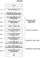
- Fig. 1 is a schematic diagram illustrating schematically a configuration of an on-vehicle device control system according to the present embodiment.
- the on-vehicle device control system performs light distribution control of a headlight, drive control of a wiper and control of other on-vehicle devices by using captured image data captured around the own vehicle as a capturing area (especially, ahead in the travelling direction) by using an imaging apparatus installed on the own vehicle 100, such as a car which is a moving body.
- the imaging apparatus provided in the on-vehicle device control system according to the present embodiment is provided in the imaging unit 101, and images a front area in the traveling direction of the travelling own vehicle 100 as a capturing area.
- the imaging apparatus is provided, for example, at around a rear-view mirror (not shown) of the front windscreen 105 of the own vehicle 100. Captured image data captured by the imaging apparatus of the imaging unit 101 are input to an image analysis unit 102.
- the image analysis unit 102 analyzes captured image data transmitted from the imaging apparatus, calculates a position (direction and distance) of another vehicle present ahead of the own vehicle 100, detects adhering matter such as raindrops or foreign material adhering to the front windscreen 105, or detects a detection object such as a white line (marking line) on a road surface present in the capturing area.
- a detection object such as a white line (marking line) on a road surface present in the capturing area.
- a result of calculation by the image analysis unit 102 is transmitted to a headlight control unit 103.
- the headlight control unit 103 generates a control signal for controlling a headlight 104 which is an on-vehicle device of the own vehicle 100, for example, from position data of the other vehicle calculated by the image analysis unit 102. Specifically, for example, switching between a low beam and a high beam for the headlight 104 is controlled or the headlight 104 is partially shielded so that a view of the driver of the own vehicle 100 is ensured, while preventing glare of a headlight of the own vehicle 100 toward the driver of the preceding vehicle or the oncoming vehicle.
- the result of calculation by the image analysis unit 102 is also transmitted to a wiper control unit 106.
- the wiper control unit 106 controls a wiper 107 that removes the adhering matter such as raindrops or foreign material adhering to the front windscreen 105 of the own vehicle 100.
- the wiper control unit 106 receives the result of detection for adhering matter detected by the image analysis unit 102 and generates a control signal for controlling the wiper 107.
- the wiper 107 operates so as to ensure the view of the driver of the own vehicle 100.
- the result of calculation by the image analysis unit 102 is also transmitted to a vehicle travelling control unit 108.
- the vehicle travelling control unit 108 based on the white line detection result detected by the image analysis unit 102, in the case where the own vehicle 100 deviates from a traffic lane area zoned by white lines or the like, gives an alarm to the driver of the own vehicle 100, or performs drive assist control such as control of a steering wheel or a brake.
- the vehicle travelling control unit 108 based on the position data of the other vehicle detected by the image analysis unit 102, in the case where the distance to the preceding vehicle decreases or the like, gives an alarm to the driver of the own vehicle 100 or performs the drive assist control such as the control of the steering wheel or the brake.
- Fig. 2 is a schematic diagram illustrating schematically a configuration of the imaging unit 101.
- Fig. 3 is an explanatory diagram illustrating a schematic configuration of the imaging apparatus 200 provided in the imaging unit 101.
- the imaging unit 101 includes the imaging apparatus 200 as an imaging means, a light source 202 as a light emitting means and an imaging case 201 for accommodating the imaging apparatus 200 and the light source 202.
- the imaging unit 101 is installed on the side of the inner wall surface of the front windscreen 105 of the own vehicle 100.
- the imaging apparatus 200 includes an imaging lens 204, an optical filter 205 and an image sensor 206.
- the light source 202 is arranged so that when the light source 202 emits light including infrared light toward the front windscreen 105 and the light is reflected at an interface between the raindrops adhering to the outer wall surface of the front windscreen 105 and air, the reflected light enters into the imaging apparatus 200.
- the adhering matter adhering to the outer wall surface of the front windscreen 105 is a light-impermeable foreign material
- the reflected light enters into the imaging apparatus 200.
- the light source 202 is for detecting the adhering matter adhering to the outer wall surface of the front windscreen 105 (in the following, an example where the adhering matter is raindrops will be exemplified).
- the adhering matter is raindrops will be exemplified.
- the emitted light after passing through the outer wall surface of the front windscreen 105, is reflected at an interface between the raindrops 203 and air, and the reflected light passes through the outer wall surface of the front windscreen 105 again, thereby the reflected light enters into the imaging apparatus 200.
- a contrast difference in brightness
- the imaging unit 101 covers the imaging apparatus 200 and the light source 202 with the imaging case 201 along with the front windscreen 105.
- the imaging case 201 covers the imaging apparatus 200 and the light source 202 with the imaging case 201 along with the front windscreen 105.
- a flow path through which air flows may be provided in a part of the imaging case 201 so that the condition in the part of the front windscreen 105 opposed to the imaging apparatus 200 is the same as that in the other part.
- a focal position of the imaging lens 204 is set at infinity or between infinity and the front windscreen 105. Accordingly, not only in the case of detecting raindrops 203 adhering to the surface of the front windscreen 105, but also in the case of detecting a preceding vehicle or an oncoming vehicle or detecting a white line, proper information can be acquired from the captured image data by the imaging apparatus 200.
- a shape recognition process is performed that determines whether a raindrop candidate image in the captured image data has a circular shape, and recognizes the raindrop candidate image to be a raindrop image.
- the imaging lens 204 focusing the raindrops 203 on the outer wall surface of the front windscreen 105
- the focal position of the imaging lens 204 is set at infinity or between infinity and the front windscreen 105, the image is out of focus, and a shape recognition rate of raindrop (circular shape) is enhanced, thereby the raindrop detection performance becomes higher.
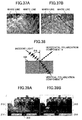
- Fig. 4 is an explanatory diagram illustrating infrared light image data which are captured image data for detecting raindrops in the case where the imaging lens 204 focuses on the raindrops 203 on the outer wall surface of the front windscreen 105.
- Fig. 5 is an explanatory diagram illustrating infrared light image data which are captured image data for detecting raindrops in the case where the imaging lens 204 is focused at infinity.
- the imaging lens 204 When the imaging lens 204 focuses on the raindrops 203 on the outer wall surface of the front windscreen 105, as shown in Fig. 4 , even a background image 203a projected in the raindrops is captured.
- the background image 203a may cause an erroneous detection of the raindrops 203.
- brightness of only a part of the raindrop 203b having an arcuate shape may become higher.
- the shape of the part having higher brightness, i.e. the shape of the image of the raindrop changes depending on a direction of sunlight or a position of a street light.
- the imaging lens 204 is focused at infinity, as shown in Fig. 5 , the image is out of focus. Then, the background image 203a projected in the raindrops 203 is not reflected in the captured image data, and occurrence of the erroneous detection for the raindrops 203 is suppressed. Moreover, according to the image being out of focus, the degree of change in shape of the image of the raindrops depending on the direction of sunlight or the position of a street light becomes smaller, and the shape of the image of the raindrop is always approximately circular. Accordingly, the processing load of the shape recognition process in processing the shape of the image of the raindrops becomes smaller, and the recognition accuracy increases.
- the imaging lens 204 is focused at infinity, when a taillight of a preceding vehicle which travels at a great distance is recognized, a number of light receiving elements on the image sensor 206 receiving light from the taillight may become approximately one. In this case, described later in details, the light of the taillight may not be received by a light receiving element for red light, which receives red light of taillights. Then, the taillight cannot be recognized, and the preceding vehicle is not detected.
- the focal point of the imaging lens 204 is preferably set less than infinity.
- an image of the taillight of the preceding vehicle is out of focus, and the number of light receiving elements receiving the light from the taillight can be increased. Then, the recognition accuracy for a taillight is enhanced and the detection accuracy of a preceding vehicle increases.
- a light-emitting diode (LED) or a laser diode (LD) may be used for the light source 202 in the imaging unit 101.
- a wavelength of emitted light from the light source 202 may be a wavelength of visible light or infrared light.
- a wavelength which is greater than that of visible light and can be detected in light reception sensitivity of the image sensor for example a wavelength in a range of the infrared light, greater than or equal to 800 nm and less than or equal to 1000 nm, is preferably selected.
- the light source 202 according to the present embodiment emits light with a wavelength in the range of the infrared light.
- the image sensor 206 of the imaging apparatus 200 receives, in addition to the light with wavelength of infrared light from the light source 202, disturbance light having a large amount of light including light with wavelength of infrared light such as sunlight, for example. Accordingly, in order to distinguish the light with wavelength of infrared light from the light source 202 from such disturbance light, an amount of luminescence of the light source 202 is required to be sufficiently greater than the amount of light of the disturbance light. But, such a light source 202 with a great amount of luminescence is often difficult to be used.
- the present embodiment for example, it is configured so that light from the light source 202 is received by the image sensor 206 via a cut filter that cuts light having a wavelength shorter than the light emission wavelength of the light source 202, as shown in Fig. 6 , or via a bandpass filter that has a peak of a transmission factor at about the light emission wavelength of the light source 202, as shown in Fig. 7 .
- a cut filter that cuts light having a wavelength shorter than the light emission wavelength of the light source 202, as shown in Fig. 6
- a bandpass filter that has a peak of a transmission factor at about the light emission wavelength of the light source 202, as shown in Fig. 7 .
- an image area of the captured image data is divided into a raindrop detection image area for detecting the raindrops 203 on the front windscreen 105, and a vehicle detection image area for detecting a preceding vehicle, an oncoming vehicle or a white line.
- the optical filter 205 is provided with a filter that removes the wavelength band other than the light with wavelength of infrared light emitted from the light source 202 only for a part corresponding to the raindrop detection image area.
- Fig. 8 is a diagram illustrating a front view of a pre-stage filter 210 provided in the optical filter 205.
- Fig. 9 is an explanatory diagram illustrating an example of an image of the captured image data.
- the optical filter 205 has a configuration that the pre-stage filter 210 and a post-stage filter 220 are overlaid in the light transmission direction.
- An area of the pre-stage filter 210 is divided, as shown in Fig. 8 , into an infrared light cut filter area 211 provided at a position corresponding to upper two-thirds of the captured image which is the vehicle detection image area 213 and an infrared light transmission filter area 212 provided at a position corresponding to lower one-third of the captured image which is the raindrop detection image area 214.
- the cut filter shown in Fig. 6 or the bandpass filter shown in Fig. 7 is used.
- images of a headlight of an oncoming vehicle, a taillight of a preceding vehicle and a white line often appear mainly above a central part of the captured image, and an image of the nearest road surface ahead of the own vehicle often appears in a lower part of the captured image. Accordingly, information required for recognizing a headlight of an oncoming vehicle, a taillight of a preceding vehicle and a white line is concentrated in an upper part of the captured image. In the recognition of them, information in the lower part of the captured image is not important.
- the lower part of the captured image is preferably allocated to the raindrop detection image area 214 and the remaining part is preferably allocated to the vehicle detection image area 213, as shown in Fig. 9 .
- the area of the pre-stage filter 210 is divided corresponding to the above allocation.
- the raindrop detection image area 214 may be provided below the vehicle detection image area 213 in the captured image.
- the raindrop detection image area 214 may be provided above the vehicle detection image area 213, or the raindrop detection image areas 214 may be provided above and below the vehicle detection image area 213.
- an image of a hood of the own vehicle may enter into the lower part in the capturing area.
- sunlight or light from a preceding vehicle reflected on the hood of the own vehicle may become disturbance light.
- the disturbance light included in the captured image data may cause false recognition of a headlight of an oncoming vehicle, a taillight of a preceding vehicle and a white line.
- the cut filter shown in Fig. 6 or the bandpass filter shown in Fig. 7 is arranged at the position corresponding to the lower part of the captured image, the disturbance light such as sunlight or light from a taillight of a preceding vehicle reflected on the hood is removed. Therefore, the recognition accuracy for a headlight of an oncoming vehicle, a taillight of a preceding vehicle and a white line increases.
- the cut filter shown in Fig. 6 or the bandpass filter shown in Fig. 7 is provided in the upper part of the pre-stage filter 210 of the optical filter 205.
- a taillight in the captured image is recognized, thereby the preceding vehicle is detected.
- an amount of light of the taillight is smaller than that of a headlight of an oncoming vehicle, and due to disturbance light such as street light, the detection of the taillight with high accuracy only from the brightness data is difficult. Therefore, it is required that spectral information is used for the detection of the taillight, and based on an amount of light of the received red light the taillight is recognized.
- a red light filter corresponding to the color of the taillight or a cyan filter, which transmits only a wavelength band of color of the taillight is arranged in the post-stage filter 220 of the optical filter 205, thereby an amount of light of the received red light can be detected.
- each of the light receiving elements included in the image sensor 206 has sensitivity also for light of wavelength band of infrared light
- the image sensor 206 receives light including wavelength band of infrared light
- the obtained captured image presents a red tone as a whole.
- the recognition of a red image part corresponding to the taillight may become difficult.
- a part in the pre-stage filter 210 of the optical filter 205 corresponding to the vehicle detection image area 213 is assigned to the infrared light cut filter area 211. Therefore, the wavelength band of infrared light is removed from the part of the captured image data used for recognizing the taillight, and the recognition accuracy for the taillight increases.
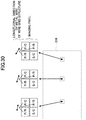
- Fig. 10 is an explanatory diagram illustrating in detail the object detection apparatus according to the present embodiment.
- the imaging apparatus 200 which configures the object detection apparatus according to the present embodiment, mainly includes an imaging lens 204, an optical filter 205, a sensor substrate 207 including an image sensor 206 having a pixel array, which is arranged two dimensionally, and a signal processing unit 208 for generating captured image data, in which analogue electric signals output (amount of light of the light received by each of the light receiving elements on the image sensor 206) from the sensor substrate 207, are converted into digital electric signals, and outputting the captured image data.
- Light from the capturing area including an object (detection object) passes through the imaging lens 204, transmits through the optical filter 205, and is converted into an electric signal according to its optical intensity at the image sensor 206.
- the signal processing unit 208 When the electric signal (analog signal) output from the image sensor 206 is input, in the signal processing unit 208, from the electric signal, a digital signal indicating brightness at each of the pixels on the image sensor 206, as captured image data, is output along with vertical and horizontal synchronization signals to a unit of the latter stage. Moreover, since the signal processing unit 208 also functions as an exposure amount changing means for performing exposure control for the image sensor 206 or an exposure condition changing means, the signal processing unit is provided with an exposure amount change unit.
- the object detection apparatus illustrates an example where the image analysis unit 102 is provided with an object detection processing unit and a raindrop detection processing unit, and functions of an object detection processing means and of an adhering matter detection means in the object detection apparatus are provided in the image analysis unit 102. However, at least a part of these functions may be provided in the imaging apparatus 200.
- Fig. 11 is an enlarged schematic diagram illustrating the optical filter 205 and the image sensor 206 viewed from a direction orthogonal to a light transmission direction.
- the image sensor 206 is an image sensor using a CCD (Charge Coupled Device) which reads signals of the respective imaging pixels by performing the simultaneous exposure (global shutter) for all the imaging pixels, a CMOS (Complementary Metal Oxide Semiconductor) which reads signals of the respective imaging pixels exposed by the line exposure (rolling shutter) or the like.
- CCD Charge Coupled Device
- CMOS Complementary Metal Oxide Semiconductor
- photodiodes 206A are used for the light receiving element.
- the photodiodes 206A are arranged in an array two dimensionally one for each pixel, and a microlens 206B is provided on an incident side of each photodiode 206A so as to enhance collection efficiency.
- the image sensor 206 is connected to a PWB (Printed Wiring Board) by a wire binding method or the like, thereby the sensor substrate 207 is formed.
- PWB Print Wiring Board
- the optical filter 205 is arranged in proximity to a surface of the image sensor 206 on the side of the microlens 206B.
- the post-stage filter 220 of the optical filter 205 includes a laminate structure where a polarization filter layer 222 and a spectral filter layer 223 are sequentially formed on a transparent filter substrate 221, as shown in Fig. 11 . Both the polarization filter layer 222 and the spectral filter layer 223 are divided into areas so that each of the areas corresponds to one photodiode 206A on the image sensor 206.
- the optical filter 205 and the image sensor 206 may be configured so that there is a gap between them. However, when the optical filter 205 adheres tightly to the image sensor 206, it becomes easier to make boundaries of the respective areas on the polarization filter layer 222 and the spectral filter layer 223 of the optical filter 205 coincide with boundaries among the photodiodes 206A on the image sensor 206.
- the optical filter 205 and the image sensor 206 may be connected with a UV adhesive agent, or four side regions outside effective pixels used for imaging may be connected with the UV adhesive agent or by thermocompression bonding while being supported by spacers outside the effective pixels.
- Fig. 12 is an explanatory diagram illustrating an area division pattern on the polarization filter layer 222 and the spectral filter layer 223 of the optical filter 205 according to the present embodiment.
- Two kinds of areas are arranged on the polarization filter layer 222 and the spectral filter layer 223, respectively, so that each of the first area and the second area corresponds to one photodiode 206A on the image sensor 206.
- an amount of light received by each of the photodiodes 206A on the image sensor 206 can be acquired as polarization information or spectral information according to the kind of the area on the polarization filter layer 222 or the spectral filter layer 223 through which the received light is transmitted.
- the image sensor 206 will be explained on the assumption of the imaging elements for monochrome image.
- the image sensor 206 may include imaging elements for color image.
- a light transmission characteristic of each of the regions on the polarization filter layer 222 and the spectral filter layer 223 may be controlled according to the characteristic of a color filter attached to each of imaging pixels of imaging element for color image.
- first configuration example an example of a configuration of the optical filter 205 according to the present embodiment (hereinafter referred to as "first configuration example) will be explained.
- Fig. 13 is a cross-sectional diagram schematically illustrating an example of a configuration of layers of the optical filter 205 according to a first configuration example.
- a configuration of layers of a vehicle detection filter part 220A corresponding to the vehicle detection image area 213 is different from a configuration of layers of a raindrop detection filter part 220B corresponding to the raindrop detection image area 214.
- the vehicle detection filter part 220A includes the spectral filter layer 223, whereas the raindrop detection filter part 220B does not include the spectral filter layer 223.
- a configuration of the polarization filter layer 222 in the vehicle detection filter part 220A is different from a configuration of the polarization filter layer 225 in the raindrop detection filter part 220B.
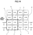
- Fig. 14 is an explanatory diagram illustrating content of information corresponding to an amount of light transmitted through the vehicle detection filter part 220A in the optical filter 205 according to the first configuration example and received by each photodiode 206A on the image sensor 206 (information of each imaging pixel).
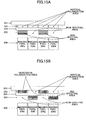
- Fig. 15A is a cross-sectional diagram schematically illustrating the vehicle detection filter part 220A of the optical filter 205 cut along reference line A-A shown in Fig. 14 and the image sensor 206.
- Fig. 15B is a cross-sectional diagram schematically illustrating the vehicle detection filter part 220A of the optical filter 205 cut along reference line B-B shown in Fig. 14 and the image sensor 206.
- the vehicle detection filter part 220A of the optical filter 205 according to the first configuration example has a laminate configuration, as shown in Figs. 15A and 15B , in which after the polarization filter layer 222 is formed on the transparent filter substrate 221 the spectral filter layer 223 is formed thereon. Then, the polarization filter layer 222 has a wire grid structure and an upper surface in the lamination direction (lower side surface in Figs. 15A and 15B ) is a corrugated surface. When the spectral filter layer 223 is formed directly on such a corrugated surface, the spectral filter layer is formed along the corrugated surface, an unevenness of a layer thickness of the spectral filter layer 223 arises, and an original spectral performance may not be obtained. Therefore, in the optical filter 205 according to the present embodiment, after filler is filled in on the upper side surface in the lamination direction in the polarization filter layer 222 to planarize the surface, the spectral filter layer 223 is formed thereon.
- a material of the filler has only not to prevent the function of the polarization filter layer 222, a corrugated surface of which is planarized by the filler, in the present embodiment, a material which does not have a polarization function is used.
- a method of applying the filler by using a spin-on-glass method may be preferably employed. But, it is not limited to this.
- a first area of the polarization filter layer 222 is a vertical polarization area that selects only a vertical polarization component, which oscillates in a direction parallel to the column (vertical direction) of the imaging pixels of the image sensor 206, and transmits the vertical polarization component.
- a second area of the polarization filter layer 222 is a horizontal polarization area that selects only a horizontal polarization component, which oscillates in a direction parallel to the row (horizontal direction) of the imaging pixels of the image sensor 206, and transmits the horizontal polarization component.
- a first area of the spectral filter layer 223 is a red spectral area that selects only light of a red wavelength band (specific wavelength band) included in a use wavelength band that can be transmitted through the polarization filter layer 222, and transmits the selected light.
- a second area of the spectral filter layer 223 is a non-spectral area that does not perform a wavelength selection and transmits light.
- the imaging pixel "a" receives light P/R of the red wavelength band (shown by reference sign “R” in Fig. 14 ) of the vertical polarization component (shown by reference sign "P” in Fig. 14 ).
- the imaging pixel "b" shown in Fig. 14 , light transmitted through the vertical polarization area (first area) in the polarization filter layer 222 of the optical filter 205 and through the non-spectral area (second area) in the spectral filter layer 223 is received. Accordingly, the imaging pixel "b” receives non-spectral (shown by reference sign "C” in Fig. 14 ) light P/C of the vertical polarization component P.
- the imaging pixel "e" receives non-spectral C light S/C of the horizontal polarization component (shown by reference sign "S" in Fig. 14 ).
- the imaging pixel "f" receives light P/R of the red wavelength band R of the vertical polarization component P, in the same way as in the imaging pixel "a".
- one image pixel for an image of a vertical polarization component of red light can be obtained from output signals of the imaging pixel "a" and the imaging pixel "f".
- One image pixel for an image of a vertical polarization component of non-spectral light can be obtained from an output signal of the imaging pixel "b”.
- One image pixel for an image of a horizontal polarization component of non-spectral light can be obtained from an output signal of the imaging pixel "e”.
- three kinds of captured image data including an image of a vertical polarization component of red light, an image of a vertical polarization component of non-spectral light and an image of a horizontal polarization component of non-spectral light, are obtained.
- a number of image pixels may become less than the number of imaging pixels, in order to obtain an image with higher resolution, a publicly-known image interpolating technique may be used.
- image pixels corresponding to the imaging pixels "a” and "f” information on the vertical polarization component P of the red light received at these imaging pixels "a” and "f” is directly used.
- an image pixel corresponding to the imaging pixel "b” for example, an average of imaging pixels "a", “c", "f” and "j” surrounding it is used as information on a vertical polarization component of red light at the image pixel.
- the image of the vertical polarization component of the red light obtained as above may be used for identifying a taillight, for example. Since in the image of the vertical polarization component of the red light a horizontal polarization component S is cut, a red image, in which a disturbance factor due to red light having great horizontal polarization component S, such as a red light reflected on a road surface or a red light from a dashboard in a room of the own vehicle 100 (reflection light) is prevented, can be obtained. Accordingly, by using the image of vertical polarization component of red light for identifying a taillight, a recognition rate for a taillight is enhanced.
- the image of the vertical polarization component of non-spectral light is used, for example, for identifying a white line or a headlight of an incoming vehicle. Since the in the image of the horizontal polarization component of the non-spectral light a horizontal polarization component S is cut, a non-spectral image, in which a disturbance factor due to white light having great horizontal polarization component S, such as a white light, e.g. a headlight, a street light or the like, reflected on a road surface or a white light from the dashboard in the room of the own vehicle 100 (reflection light) is prevented, can be obtained.
- a white light e.g. a headlight, a street light or the like
- a recognition rate thereof is enhanced.
- a reflected light from a water surface covering the road surface has much horizontal polarization component S. Accordingly, by using the image of vertical polarization component of non-spectral light for identifying a white line, it becomes possible to adequately identify a white line under a water surface on a road in the rain, and the recognition rate is enhanced.
- a pixel value represents an index value comparing respective pixel values between the image of vertical polarization component of non-spectral light and the image of horizontal polarization component of non-spectral light, as described later, it becomes possible to accurately identify a metal body within the image area, a dry and wet state of the road surface, a solid body in the image area, a white line on a road in the rain, or the like.
- a difference image in which pixel values represent difference values between pixel values of the image of vertical polarization component of non-spectral light and of the image of horizontal polarization component of non-spectral light a ratio image in which pixel values represent ratios of pixel values between these images, a differential polarization degree image in which pixel values represent ratio of the difference between the pixel values of these images to the sum of the pixel values of these images, or the like may be used.
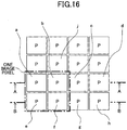
- Fig. 16 is an explanatory diagram illustrating content of information corresponding to an amount of light transmitted through the raindrop detection filter part 220B in the optical filter 205 according to the first configuration example and received by each photodiode 206A on the image sensor 206 (information of each imaging pixel).
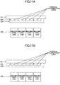
- Fig. 17A is a cross-sectional diagram schematically illustrating the raindrop detection filter part 220B of the optical filter 205 cut along reference line A-A shown in Fig. 16 and the image sensor 206.
- Fig. 17B is a cross-sectional diagram schematically illustrating the raindrop detection filter part 220B of the optical filter 205 cut along reference line B-B shown in Fig. 16 and the image sensor 206.
- a polarization filter layer 225 having a wire grid structure is formed on the filter substrate which is shared with the vehicle detection filter part 220A.
- An upper side surface of the polarization filter layer 225 in the lamination direction is filled with filler to be planarized along with the polarization filter layer 222 of the vehicle detection filter part 220A.
- a spectral filter layer 223 is not laminated, different from the vehicle detection filter part 220A.
- a view inside the own vehicle 100 may be reflected on an inner wall surface of the front windscreen 105.
- This reflection is by light reflected regularly on the inner wall of the front windscreen 105.
- This reflection is disturbance light with a relatively large light strength since it is a regular reflection light. Accordingly, when the reflection is projected onto the raindrop detection image area 214 with raindrops, the detection accuracy for raindrops decreases.
- a regular reflection light which is a light emitted from the light source 202 and reflected regularly on the inner wall surface of the front windscreen 105, is projected onto the raindrop detection image area 214 along with the raindrops, the regular refection light also becomes disturbance light and lowers the detection accuracy for raindrops.
- polarization components are polarization components, polarization directions of which are orthogonal to the light source incidence plane, i.e. horizontal polarization components S which oscillate parallel to the row of the imaging pixels (horizontal direction) of the image sensor 206.
- a transmission axis is set so as to transmit only a polarization component having a polarization direction parallel to a virtual plane including a light axis of a light from the light source 202 to the front windscreen 105 and a light axis of the imaging lens 204 (light source incidence plane), i.e. a vertical polarization component P that oscillates parallel to the column of the imaging pixels (vertical direction) of the image sensor 206.
- light transmitted through the polarization filter layer 225 of the raindrop detection filter part 220B has only vertical polarization component P, and horizontal polarization component S, which occupies most of disturbance light such as reflection light on the inner wall surface of the front windscreen 105 or regularly reflected light from the light source 202 reflected regularly on the inner wall surface of the front windscreen 105, can be cut.
- the raindrop detection image area 214 becomes a vertical polarization image by the vertical polarization component P which is less affected by disturbance light, and the detection accuracy of raindrops based on captured image data in the raindrop detection image area 214 is enhanced.
- the infrared light cut filter area 211 and the infrared light transmission filter area 212 included in the pre-stage filter 210 are formed respectively by multi-layer films, layer structures of which are different from each other.
- Such a pre-stage filter 210 is manufactured according a production method in which, for example, a part of the infrared light transmission filter area 212 is formed by a vacuum deposition or the like while masking a part of the infrared light cut filter area 211, and the part of the infrared light cut filter area 211 is formed by the vacuum deposition or the like while masking the part of the infrared light transmission filter area 212.
- both the polarization filter layer 222 of the vehicle detection filter part 220A and the polarization filter layer 225 of the raindrop detection filter part 220B have the wire grid structure for dividing into areas in two dimensional directions.
- the polarization filter layer 222 includes two kinds of areas divided in units of imaging pixels, transmission axes of which are orthogonal to each other (vertical polarization area and horizontal polarization area).
- the polarization filter layer 225 includes one kind of area divided in units of imaging pixels, having a transmission axis that transmits only the vertical polarization component P.
- the polarization filter layers 222 and 225 having different configurations on the same transparent filter substrate 221, for example, by adjusting a groove direction of a template (corresponding to a mold) for performing patterning for metal wires having the wire grid structure, it is easy to adjust the metal wire for each area in the longitudinal direction.
- the infrared light cut filter area 211 may not be provided in the optical filter 205 and, for example, the infrared light cut filter area 211 may be provided in the imaging lens 204. In this case, the manufacturing of the optical filter 205 becomes simple.
- a spectral filter layer that transmits only vertical polarization component P may be formed on the raindrop detection filter part 220B in the post-stage filter 220. In this case, it is not necessary to form the infrared light cut filter area 211 in the pre-stage filter 210.
- the polarization filter layer does not always have to be provided.
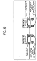
- Fig. 18 is an explanatory diagram illustrating various light related to the raindrop detection.
- the light source 202 is arranged so that regularly reflected light on the outer wall surface of the front windscreen 105 approximately coincides with the light axis of the imaging lens 204.
- a light ray A is a light ray emitted from the light source 202 and passing through the front windscreen 105.
- a raindrop 203 does not adhere to the outer wall surface of the front windscreen 105
- light emitted from the light source 202 to the front windscreen 105 passes through the front windscreen 105 and leaks directly to the outside of the own vehicle 100.
- a light source having a wavelength and a light amount of the eye-safe band is preferably selected.
- a light ray B in Fig. 18 is a light ray emitted from the light source 202, reflected regularly on the inner wall surface of the front windscreen 105 and entering the imaging apparatus 200. A part of the light emitted from the light source 202 to the front windscreen 105 is reflected regularly on the inner wall surface of the front windscreen 105. It is generally known that for a polarization component of this regularly reflected light (light ray B) an S polarization component (horizontal polarization component S) oscillating in the direction orthogonal to the entrance plane (direction perpendicular to the plane of paper of Fig. 18 ) is dominant.
- the regularly reflected light (light ray B), which is emitted from the light source 202 and reflected regularly on the inner wall surface of the front windscreen 105, does not fluctuate by a presence or an absence of a raindrop 203 adhering to the outer wall surface of the front windscreen 105. Therefore, the light ray B is not only an unnecessary light for detecting raindrops, but also a disturbance light that decreases the detection accuracy for detecting raindrops.
- the light ray B (horizontal polarization component S) is cut by the polarization filter layer 225 of the raindrop detection filter part 220B, and the decrease in the raindrop detection accuracy due to the light ray B can be suppressed.
- a light ray C in Fig. 18 is a light ray emitted from the light source 202, passing through the inner wall surface of the front windscreen 105, then reflected by a raindrop adhering to the outer wall surface of the front windscreen 105 and entering the imaging apparatus 200.
- a part of the light emitted from the light source 202 to the front windscreen 105 passes through the inner wall surface of the front windscreen 105.
- a vertical polarization component P is more dominant than a horizontal polarization component S.
- the light passing through the inner wall surface of the front windscreen 105 does not leak to the outside as the light ray A, but is reflected to multiply inside the raindrop, passes through the front windscreen 105 again toward the side of the imaging apparatus 200, and enters the imaging apparatus 200. Then, since the infrared light transmission filter area 212 of the pre-stage filter 210 in the optical filter 205 of the imaging apparatus 200 is configured so as to transmit an emission wavelength (infrared light) of the light source 202, the light ray C passes through the infrared light transmission filter area 212.
- the longitudinal direction of the metal wires having the wire grid structure is formed so as to transmit a vertical polarization component P
- the light ray C passes through also the polarization filter layer 225. Accordingly, the light ray C reaches the image sensor 206, and the detection of raindrops is performed according to the received amount of light.
- a light ray D in Fig. 18 is a light ray passing through the front windscreen 105 from the outside of the front windscreen 105 and entering toward the raindrop detection filter part 220B of the imaging apparatus 200.
- This light ray D also can be a disturbance light upon detecting raindrops, but most of the light ray D is cut by the infrared light transmission filter area 212 of the pre-stage filter 210 in the optical filter 205. Accordingly, the decrease in the raindrop detection accuracy due to the light ray D can be suppressed.
- a light ray E in Fig. 18 is a light ray passing through the front windscreen 105 from the outside of the front windscreen 105 and entering toward the vehicle detection filter part 220A of the imaging apparatus 200.
- An infrared band of the light ray E is cut by the infrared light cut filter area 211 of the pre-stage filter 210 in the optical filter 205, and only a light of visible light band is captured.
- the captured image is used for detecting a headlight of an oncoming vehicle, a taillight of a preceding vehicle and a white line.
- the polarization filter layer 225 of the raindrop detection filter part 220B is divided into areas so that plural polarization filter areas, transmission axis directions of which are different from each other, are repeated in the two dimensional array direction of the imaging pixels in units of imaging pixels.
- the transmission axis is set so as to transmit only a polarization component, a polarization direction of which is parallel to a virtual plane including a light axis of light from a light source and the light axis of the imaging lens 204, wherein an incident light quantity of the light from the light source into the polarization filter area is the greatest among the ones from plural light sources 202.
- the transmission axis direction of the polarization filter layer 225 which can appropriately remove the disturbance light reflected regularly on the inner wall surface of the front windscreen 105, varies according to a position on the inner wall surface of the front windscreen 105 at which the disturbance light entering each location of the polarization filter layer 225 is reflected.
- the front windscreen 105 of a vehicle not only slopes downward toward the front, but also is curved backward greatly from a center to both ends in the horizontal direction so as to enhance the aerodynamic characteristic.
- the raindrop detection image area 214 of the captured image although in the central portion of the image a disturbance light can be appropriately cut, in the edge portion of the image the disturbance light may not be cut appropriately.
- Fig. 19 is an explanatory diagram illustrating an example that longitudinal directions of the metal wires of the wire grid structure are different from each other at respective points (points 1 to 3) on the polarization filter layer 225.
- the post-stage filter 220 having the polarization filter layer 222 divided into areas, as shown in Fig. 14 , and the spectral filter layer 223 is provided nearer the side of the image sensor 206 than the pre-stage filter 210.
- the pre-stage filter 210 may be provided nearer the side of the image sensor 206 than the post-stage filter 220.
- second configuration example another configuration example (hereinafter, referred to as "second configuration example") of the optical filter 205 according to the present embodiment will be explained. Meanwhile, in a following explanation of the optical filter 205, since configurations of the pre-stage filter 210 and the raindrop detection filter part 220B of the post-stage filter 220 are the same as in the first configuration example, explanations of them will be omitted and only the vehicle detection filter part 220A of the post-stage filter 220 will be explained.
- Fig. 20 is an explanatory diagram illustrating content of information corresponding to an amount of light transmitted through the optical filter 205 according to the second configuration example and received by each photodiode 206A on the image sensor 206 (information of each imaging pixel).
- Fig. 21A is a cross-sectional diagram schematically illustrating the optical filter 205 cut along reference line A-A shown in Fig. 20 and the image sensor 206.
- Fig. 21B is a cross-sectional diagram schematically illustrating the optical filter 205 cut along reference line B-B shown in Fig. 20 and the image sensor 206.
- the first area in the spectral filter layer 223 is a red spectral area that selects only light of the red wavelength band and transmits it.
- the first area is a cyan spectral area that selects only light of a cyan color wavelength band (shown by Cy in Fig. 20 ) which is included in the use wavelength band that can be transmitted through the polarization filter layer 222, and transmits the selected light.
- the other configurations are the same as in the first configuration example.
- one image pixel for an image of a vertical polarization component of cyan light can be obtained from output signals of the imaging pixel "a" and the imaging pixel "f".
- One image pixel for an image of a vertical polarization component of non-spectral light can be obtained from an output signal of the imaging pixel "b”.
- One image pixel for an image of a horizontal polarization component of non-spectral light can be obtained from an output signal of the imaging pixel "e”.
- a comparative image between the image of vertical polarization component of cyan light and the image of vertical polarization component of non-spectral light can be used.
- an identification of a taillight with high accuracy becomes possible. That is, a received amount of light from a taillight at an imaging pixel transmitted through the cyan spectral area is small, but a received amount of light at an imaging pixel transmitted through the non-spectral area is great.
- the cyan spectral area using a cyan filter that transmits only a light of cyan color is used instead of the red spectral area using the red filter in the first configuration example, an ability for discriminating a taillight of a preceding vehicle which is close to the own vehicle from a headlight of an oncoming vehicle is higher than that in the first configuration example.
- a received amount of light from the taillight of the preceding vehicle which is close to the own vehicle through the red spectral area may be too great to lose light reception sensitivity, and the received amount of light is saturated. Therefore, the recognition rate of the taillight of the preceding vehicle which is close to the own vehicle may decrease.
- the received amount of light from the taillight of the preceding vehicle which is close to the own vehicle through the cyan spectral area is not saturated, and the decrease in the recognition rate of the taillight of the preceding vehicle which is close to the own vehicle can be prevented.
- Fig. 22 is an explanatory diagram illustrating content of information corresponding to an amount of light transmitted through the optical filter 205 according to the third configuration example and received by each photodiode 206A on the image sensor 206 (information of each imaging pixel).
- Fig. 23A is a cross-sectional diagram schematically illustrating the optical filter 205 cut along reference line A-A shown in Fig. 22 and the image sensor 206.
- Fig. 23B is a cross-sectional diagram schematically illustrating the optical filter 205 cut along reference line B-B shown in Fig. 22 and the image sensor 206.
- Configurations of divided areas of the polarization filter layer 222 and the spectral filter layer 223 according to the third configuration example are the same as in the first configuration example.
- an aperture restriction part for restricting a received amount of light is provided corresponding to the non-spectral area in the spectral filter layer 223.
- three kinds of captured image data including an image of a vertical polarization component of red light, an image of a vertical polarization component of non-spectral light and an image of a horizontal polarization component of non-spectral light, are obtained.
- the image of vertical polarization component of non-spectral light and the image of horizontal polarization component of non-spectral light are generated by lesser amounts of received light than those in the first configuration example.
- the configuration of restricting the received amount of light transmitted through the non-spectral area in the spectral filter layer 223 includes a configuration, in which a wire grid structure having a circular shape is formed in a central portion of the imaging pixel of the polarization filter layer 222 and a solid film of aluminum is formed around it, corresponding to the non-spectral area in the spectral filter layer 223, as shown in Fig. 24 .
- a wire grid structure having a circular shape is formed in a central portion of the imaging pixel of the polarization filter layer 222 and a solid film of aluminum is formed around it, corresponding to the non-spectral area in the spectral filter layer 223, as shown in Fig. 24 .
- the shape of area, in which the wire grid structure is formed is not limited to a circle as shown in Fig. 24 .
- the shape may be an approximate rectangle, as shown in Fig. 25 .
- the shape of area has a corner, as shown in Fig. 25 , when roundness is formed at the corner, it becomes easier to obtain a shape dimension by etching or the like.
- the polarization filter layer 222 having the wire grid structure is generally manufactured by a production method in which, for example, after uniformly forming an aluminum film on the transparent filter substrate 221, the aluminum film is partially removed by etching or the like, and thereby the wire grid structure is obtained.
- the aperture can be restricted. Accordingly, the manufacturing process can be simplified compared with the case of performing a process for the aperture restriction separately from the polarization filter layer 222.
- an aperture restriction layer may be provided separately from the polarization filter layer 222.
- a wire grid structure is not formed, but an aperture part for directly transmitting light is formed.
- the shield area for restricting the aperture is not limited to a reflective film such as the above-described aluminum film.
- the shield area may be formed of, for example, a film that absorbs light.
- the shield area may be formed of a solid film of black resist.
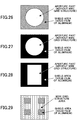
- the shape of the aperture part is not limited to a circle as shown in Fig. 27 .
- the shape may be an approximate rectangle, as shown in Fig. 28 . In the case where the shape of area has a corner, as shown in Fig. 28 , when roundness is formed at the corner, it becomes easier to obtain a shape dimension by etching or the like.
- the number of the aperture parts that transmits light for one imaging pixel is not limited to one.
- Plural aperture parts of wire grid structure areas may be formed for one imaging pixel.
- the number of the shield areas for one imaging pixel is not limited to one.
- Plural shield areas may be formed for one imaging pixel.
- the shield area is not necessarily provided in the edge portion of the imaging pixel.
- the imaging pixel may have a configuration in which solid films of aluminum are arranged in the wire grid structure.
- three kinds of captured image data including an image of vertical polarization component of red light which is the same as in the first configuration example, and an image of a vertical polarization component of non-spectral light and an image of a horizontal polarization component of non-spectral light, received amounts of light of which are restricted compared with the first configuration example, are obtained.
- an oncoming vehicle is detected from a result of an identification of a headlight using the image of vertical polarization component of non-spectral light or the image of horizontal polarization component of non-spectral light.
- taillights or headlights are paired with each other which are separated in the horizontal direction from each other by a predetermined distance. Therefore, upon detecting a preceding vehicle or an oncoming vehicle, using this property, when two image parts of taillights or headlights are separated from each other by a predetermined distance, a pair of taillights or a pair of headlights is recognized as that of a preceding vehicle or of an oncoming vehicle. At this time, since a light amount of the headlight is greater than that of the taillight, when the light reception sensitivity is set so as to receive light from the taillight properly, the received amount of light from the headlight is saturated, and an image area which is recognized as a headlight expands.
- the image areas which are originally recognized as two separated headlights becomes one image area, and the image area of the headlights cannot be recognized properly.
- the recognition rate of the oncoming vehicle thus decreases.
- the light reception sensitivity is set so as to receive light from the headlight properly, the received amount of light from the taillight is insufficient, and the image area of the taillight cannot be recognized properly. Then, the recognition rate of the preceding vehicle decreases.
- the reception sensitivity is set to fit a taillight identified by using the image of vertical polarization component of red light, a received amount of which is not restricted, the saturation of the received amount of light of the headlight is prevented.
- the respective image areas of headlights can be identified individually, and the decrease in the recognition rate of an oncoming vehicle is suppressed.
- the identification of a headlight can be balanced with the identification of a taillight without the above-described disadvantage.
- the polarization filter layer 222 provided in the post-stage filter 220 of the optical filter 205 is, as described above, divided into vertical polarization areas (first areas), each of which selects only a vertical polarization component P and transmits it; and horizontal polarization areas (second areas), each of which selects only a horizontal polarization component S and transmits it, in units of imaging pixels.
- first areas vertical polarization areas
- second areas horizontal polarization areas
- an image of the vertical polarization component, in which a horizontal polarization component S is cut can be obtained based on image data of the imaging pixels that receive light transmitted through the vertical polarization area.
- an image of the horizontal polarization component, in which a vertical polarization component P is cut can be obtained from image data of imaging pixels that receive light transmitted through the horizontal polarization area.
- the surface of the front windscreen 105 is a flat plane
- the polarization direction (transmission axis) of the vertical polarization area or the horizontal polarization area with respect to the surface of the front windscreen 105
- an image of vertical polarization component or an image of horizontal polarization component in which a reflection on the front windscreen 105 is appropriately cut can be obtained.
- the front windscreen 105 of vehicle not only slopes downward toward the front, but also is curved backward greatly from a center to both ends in the horizontal direction so as to enhance the aerodynamic characteristic.
- the polarization direction (transmission axis) of the vertical polarization area or the horizontal polarization component in the polarization filter layer 222 of the optical filter 205 is uniform at any position of area, for example, although the reflection from the front windscreen 105 is appropriately cut in the central portion of a captured image, the reflection from the front windscreen 105 in the edge portion of the captured image may not be cut appropriately.
- Fig. 30 is an explanatory diagram illustrating a longitudinal direction of a metal wire of a wire grid structure in the polarization filter layer 222 of the optical filter 205 according to the fourth configuration example.
- Configurations of divided areas of the polarization filter layer 222 and the spectral filter layer 223 of the optical filter 205 according to the fourth configuration example are the same as in the first configuration example.
- the polarization direction (transmission axis) of the vertical polarization area of the polarization filter layer 222 is not uniform.
- the vertical polarization area of the polarization filter layer 222 is formed so that an angle between the polarization direction (transmission axis) and the vertical direction increases as the vertical polarization area is closer to the edge portion in the horizontal direction of the polarization filter layer 222, adjusting to a curve of the front windscreen 105.
- the polarization filter layer 222 according to the fourth configuration example is formed so that an angle between the longitudinal direction of the metal wire of the wire grid structure and the horizontal direction becomes larger as the vertical polarization area is closer to the edge portion in the horizontal direction.
- the vertical polarization areas are formed in the wire grid structure, it is possible to form a lot of areas in tiny units of imaging pixels, which differ in polarization directions.
- the transparent filter substrate 221 is formed of a transparent material that can transmit light of use band (in the present embodiment, visible light region and infrared region), e.g. glass, sapphire, crystal or the like.
- a transparent material that can transmit light of use band in the present embodiment, visible light region and infrared region
- glass especially a silica glass which is cheap and durable (refraction index is 1.46) or tempax glass (refraction index is 1.51) can be preferably used.
- the polarization filter layer 222 formed on the transparent filter substrate 221 is configured with polarizers formed in the wire grid structure, as shown in Fig. 31 .
- the wire grid structure is a structure in which metal wires (conductor wires) formed of metal such as aluminum extending in a specified direction are arrayed at a specified pitch. According to a sufficiently small wire pitch in the wire grid structure compared with a wavelength band of incident light (for example, smaller than one-half), most of light of an electric field vector component oscillating parallel to the longitudinal direction of the metal wire is reflected and most of light of an electric field vector component oscillating perpendicular to the longitudinal direction of the metal wire is transmitted. Therefore it can be used as a polarizer for producing a single polarization.
- an extinction ratio of the polarizer of the wire grid structure increases, and furthermore for the metal wire which is greater than or equal to a predetermined width for a periodic width, the transmission factor decreases.
- a shape of a cross section orthogonal to the longitudinal direction of the metal wire is a taper shape, wavelength dispersibilities in the transmission factor and the polarization degree are small in a wide band and a characteristic of high extinction ratio is exhibited.
- the polarization filter layer 222 is formed in the wire grid structure, the following effects are exhibited.
- the wire grid structure can be formed by using a widely known semiconductor manufacturing process. Specifically, after evaporating an aluminum thin film on the transparent filter substrate 221, patterning is performed, and a sub wavelength rugged structure of the wire grid structure is formed by using a method such as metal etching. According to the above-described manufacturing process, the longitudinal direction of the metal wire i.e. the polarization direction (polarization axis) can be adjusted with an accuracy corresponding to the size of the imaging pixel in the image sensor 206 (a few ⁇ m). Accordingly, the polarization filter layer 222, in which the longitudinal direction of the metal wire, i.e. the polarization direction (polarization axis) is adjusted in each of the imaging pixels, as in the present embodiment, can be manufactured.
- the wire grid structure has an advantage that since it is made from metallic material such as aluminum, excellent heat resistance is exhibited, and it can be preferably used even under a high temperature environment such as in a vehicle compartment which is liable to be high in temperature.
- the filler 224 used for planarizing the upper side surface in the lamination direction in the polarization filter layer 222 is supplied in a concave portion between the metal wires in the polarization filter layer 222.
- an inorganic material having a refractive index lower than or equivalent to that of the transparent filter substrate 221 can be preferably used.
- the filler 224 according to the present embodiment is formed so as to cover also an upper side surface of the metal wire part of the polarization filter layer 222 in the lamination direction.
- low refraction index material a refraction index of which is extremely close to the refraction index of air (refraction index is one) is preferably used.
- a porous ceramic material which is made by dispersing fine holes in ceramic, is preferable.
- a porous silica (SiO 2 ), a porous magnesium fluoride (MgF), a porous aluminum or the like is included.
- the degree of low refraction index is determined by a number of holes in the ceramic or a size of the holes (porosity).
- a method of SOG Spin On Glass
- a solvent in which silanol (Si(OH) 4 ) is dissolved in alcohol, is spin coated on the polarization filter layer 222 formed on the transparent filter substrate 221. Then, the solvent component is vaporized by a heat treatment, and the silanol itself is dehydrated and polymerized.
- the polarization filter layer 222 has a wire grid structure of the sub wavelength size. Mechanical strength is low, and the metal wire may be damaged by a small external force. Since the optical filter 205 according to the present embodiment is desired to be arranged so as to be in close contact with the image sensor 206, there is a possibility that the optical filter 205 contacts the image sensor 206 in the manufacturing stage. In the present embodiment, the upper side surface in the lamination direction of the polarization filter layer 222, i.e. a surface on the side of the image sensor 206, is covered with the filler 224. Therefore, the damage in the wire grid structure upon contacting the image sensor 206 is suppressed.
- a protection layer such as the filler 224 is not provided for the spectral filter layer 223 laminated on the filler 224. This is because, according to an experiment by the inventors, even when the spectral filter layer 223 contacts the image sensor 206, damage to influence the captured image does not occur, and the protection layer is omitted with priority for low cost. Moreover, a height of the metal wire (convex portion) of the polarization filter layer 222 is low, i.e. less than a half of the use wavelength, whereas a height of the filter layer part forming the red spectral area or the cyan spectral area in the spectral filter layer 223 is the same as or several times the use wavelength.
- the thickness of the filler 224 increases, it becomes more difficult to ensure flatness of the upper surface, and the characteristic of the optical filter 205 is influenced. Therefore, the thickness of the filler 224 has an upper limit.
- the spectral filter layer 223 is not covered with filler.
- the filter layer part forming the red spectral area or the cyan spectral area in the spectral filter layer 223 according to the present embodiment has a multi-layer film structure in which thin films having high refractive index and thin films having low refractive index are alternately laminated. According to the above-described multi-layer film structure, a degree of freedom in setting the spectral transmission factor can be made higher by using interference of light, and by laminating thin films it is possible to realize a reflection rate close to 100% for a specific wavelength (for example, a wavelength band other than red).
- a range of the used wavelength for captured image data is approximately the visible light wavelength region (wavelength region of visible light wavelength region and infrared light wavelength region)
- an image sensor 206 having a sensitivity in the range of the used wavelength is selected and a range of a transmission wavelength of the multi-layer film part is set to be, for example, greater than or equal to 600 nm, and a cut filter for reflecting other wavelength region, as shown in Fig. 32 , is formed.
- Such a cut filter can be obtained by manufacturing a multi-layer film having a configuration such as "substrate/(0.125L 0.25H 0.125L)p/medium A" from the lower side sequentially in the laminating direction of the optical filter 205.
- substrate means the above-described filler 224.
- 0.125L represents the low refraction index material (for example, SiO 2 ) where nd/ ⁇ is 1L in the film thickness marking method.
- the film of "0.125L” means a film of low refraction index material having a film thickness which is an optical path length of 1/8 wavelength.
- n is the refraction index
- d is a thickness
- ⁇ is a cut-off wavelength.
- "0.25H” represents the high refraction index material (for example, TiO 2 ) where nd/ ⁇ is 1H in the film thickness marking method.
- the film of "0.25H” means a film of high refraction index material having a film thickness which is an optical path length of 1/4 wavelength.
- "p" indicates a number of times repeating (laminating) the combination of films indicated in the parentheses. When “p" is large, an influence such as rippling can be suppressed.
- medium A is air or resin or adhesive agent for close connection with the image sensor 206.
- the filter layer part forming the red spectral area or the cyan spectral area in the spectral filter layer 223 may be a band pass filter having a filter characteristic, as shown in Fig. 33 , where the range of transmission wavelength is a range of 600 nm to 700 nm.
- the filter layer part is the above-described band pass filter, discrimination between a near-infrared region on the side of longer wavelength than red and the red region is possible.
- the above-described band pass filter can be obtained by manufacturing the multi-layer film having a configuration such as, for example, "substrate/(0.125L 0.5M 0.125L)p(0.125L 0.5H 0.125L)q(0.125L 0.5M 0.125L)r/medium A".
- titanium dioxide (TiO 2 ) for the high refraction index material
- silica dioxide (SiO 2 ) silica dioxide
- the above-described multi-layer film is formed on the layer of the filler 224 which is formed on the transparent filter substrate 221 and the polarization filter layer 222.
- a well-known method such as evaporation may be used.
- the multi-layer film is removed at a position corresponding to the non-spectral area.
- a commonly-used method such as a lift-off processing method may be used.
- a reverse pattern to a target pattern is formed beforehand on the layer of the filler 224 with metal, photo resist or the like.
- the multi-layer film at the position corresponding to the non-spectral area is removed along with the metal or the photo resist.
- the multi-layer film structure is employed for the spectral filter layer 223, there is an advantage in that the degree of freedom in setting the spectral characteristic is high.
- a color filter used in a color sensor or the like is formed of a resist agent.
- the spectral filter layer 223 optimized for the wavelength of a taillight can be formed.
- captured image data imaged by the imaging apparatus 200 are analyzed and a taillight and a headlight of a vehicle are identified, a preceding vehicle is detected from the identified taillight and an oncoming vehicle is detected from the identified headlight. Then, switching between a high beam and a low beam of a headlight 104 is controlled or a partial shading of the headlight 104 is controlled so that prevention of glare for a driver of another vehicle is performed by avoiding high-intensity light from a headlight of the own vehicle 100 entering an eye of a driver of the preceding vehicle or the oncoming vehicle, and ensuring a visual field of the driver of the own vehicle 100 can be realized.
- intensity of light emitted from each location (light source body) in the capturing area luminance information
- distance information a distance between the light source body (other vehicle) such as a headlight or a taillight and the own vehicle
- spectral information according to comparison of a red color component of light emitted from each light source body with a white component (non-spectral) thereof
- polarization information according to comparison of a horizontal polarization component of the white component with a vertical polarization component thereof
- vertical polarization component information of the red color component in which a horizontal polarization component is cut are used.
- the luminance information will be explained.
- a headlight of the oncoming vehicle which is one of the detection objects
- a taillight of the preceding vehicle which is one of the detection objects
- the reflector is further darker.
- the taillight and the reflector of the preceding vehicle are observed more and more darkly on the image sensor 206 receiving the light, as the distance increases. Accordingly, by using the luminance (brightness information) obtained from the captured image data, a primary identification of two kinds of detection objects (headlight and taillight) and the reflector is possible.
- the distance information will be explained. Since most of the headlights and taillights have configurations of a lamp-pair, i.e. a left and right pair of lamps, the distance between the headlights or the taillights (i.e. other vehicle) and the own vehicle can be obtained by using a feature of the above configuration.
- the left and right lamps are displayed close to each other at the same position in a height direction on the captured image data imaged by the imaging apparatus 200.
- Light image areas which display the lamps respectively have almost the same size and almost the same shape. Accordingly, when the above features are made a condition, lamp image areas that satisfy the condition can be identified as a lamp-pair. Meanwhile, when the distance increases, the left and right lamps of a lamp-pair cannot be recognized as separated lamps, but are recognized as a single lamp.
- a distance to a light source in a headlight or a taillight of the lamp-pair can be calculated. That is, a distance between the left and right headlights of the vehicle and a distance between the left and right taillights of the vehicle can be approximated to be a constant value w0 (for example, 1.5 m).
- a red color image in which only red color components in the capturing area are displayed, can be generated by extracting pixel data corresponding to the imaging pixels "a", “c", “f”, “h” or the like on the image sensor 206, which receives red light (vertical polarization component) P/R, from the captured image data imaged by the imaging apparatus 200.
- the image area can be identified as a taillight image area which displays a taillight.
- a monochrome brightness image (vertical polarization component) in the capturing area can be generated by extracting only pixel data corresponding to the imaging pixels "b", "d” or the like on the image sensor 206, which receives the vertical polarization component of white light (non-spectral) P/C, from the captured image data imaged by the imaging apparatus 200. Accordingly, a brightness ratio (red color brightness ratio) between the image area on the red color image and the image area on the monochrome brightness image corresponding to the image area on the red color image can be also calculated.
- a relative ratio of the red color component included in light from a body (light source body) existing in the capturing area can be grasped. Since a red color brightness ratio of a taillight is a sufficiently higher value than a headlight or most of other light sources, by using the red color brightness ratio, accuracy in the identification of the taillight is enhanced.
- the polarization information will be explained.
- pixel data corresponding to the imaging pixels "b", “d” or the like on the image sensor 206 which receives the vertical polarization component of white light (non-spectral) P/C
- pixel data corresponding to the imaging pixels "e", “g” or the like on the image sensor 206 which receives the horizontal polarization component of white light (non-spectral) S/C
- a comparative image in which pixel values (brightness) are compared between these image data for each image pixel, can be obtained.
- a difference image in which a pixel value represents a difference value between the vertical polarization component P of white light (non-spectral) and the horizontal polarization component S of white light (non-spectral) can be obtained as the comparative image.
- a contrast between an image area (headlight image area) of direct light, which directly enters the imaging apparatus 200 from a headlight, and an image area of indirect light, which enters the imaging apparatus after reflecting on a water surface of road in the rain from the headlight can be made higher, and accuracy in the identification of the headlight is enhanced.
- a ratio image in which a pixel value represents a ratio (S/P) between the vertical polarization component P of white light (non-spectral) and the horizontal polarization component S of white light (non-spectral)
- a differential polarization degree image in which a pixel value represents a differential polarization degree ((S-P)/(S+P)) or the like is preferably used.
- a horizontal mirror surface such as a water surface
- each of the ratio (S/P) between the horizontal polarization component S and the vertical polarization component P and the differential polarization degree ((S-P)/(S+P)) becomes maximum at the specific angle (Brewster's angle).
- an asphalt surface which is a scattering plane is covered with water, and the surface of the road is in a condition close to a mirror surface.
- the reflected light of headlight from the road surface horizontal polarization component is dominant. Therefore, an image area of the reflected light of a headlight from the road surface has a great pixel value (brightness) in the ratio image or in the differential polarization degree image.
- the direct light from the headlight is basically unpolarized, the pixel value (brightness) thereof is small in the ratio image or in the differential polarization degree image. According to difference between them, the reflected light of a headlight from the road surface in the rain which has the same light amount as the direct light from the headlight can be appropriately removed, and the direct light from the headlight can be identified as distinguished from such reflected light of the headlight.
- Fig. 34 is a diagram illustrating a histogram of differential polarization degrees calculated for direct light from a headlight in a rainy day and for reflected light reflected on a rainy road surface from the headlight imaged using the imaging apparatus 200.
- the axis of ordinates indicates a frequency, which is normalized to one.
- the axis of abscissas indicates the differential polarization degree ((S-P)/(S+P)).
- the reflected light of a headlight from the road surface in the rain compared with the direct light from the headlight, has a distribution which is shifted to the direction where the horizontal polarization component S is relatively large (rightward in the drawing).
- Fig. 35 is a schematic diagram illustrating an example of a state, imaged by the imaging apparatus 200, where both a preceding vehicle and an oncoming vehicle are present ahead in the travelling direction at almost the same distances when the own vehicle travels on a rainy road surface.
- an image area having the pixel value (brightness value) of a red color image or the red color brightness ratio, described as above, greater than a predetermined threshold is identified as a taillight image area that displays the taillight of the preceding vehicle or the reflected light of the taillight from the rainy road surface.
- An image area with the pixel value or the red color brightness ratio less than or equal to the threshold is identified as a headlight image area that displays the headlight of the preceding vehicle or the reflected light of the headlight from the rainy road surface.
- direct light from the taillight or the headlight and its reflected light can be distinguished with high accuracy.
- the taillight based on the pixel value (brightness value) of the red color image of horizontal polarization component S, as described above, and its differential polarization degree or the like, by using a difference in a frequency or intensity of the horizontal polarization component, the direct light from the taillight of the preceding vehicle and the reflected light of taillight from the rainy road surface are distinguished.
- the direct light from the headlight of the preceding vehicle and the reflected light of headlight from the rainy road surface are distinguished.
- Fig. 36 is a flowchart illustrating a flow of vehicle detection processing according to the present embodiment.
- image processing is performed for image data captured by the imaging apparatus 200, and an image area considered to be a detection object is extracted. Then, the preceding vehicle or the oncoming vehicle is detected by determining which one of the two kinds of detection objects is the kind of the light source displayed on the image area.
- image data ahead of the own vehicle, captured by the image sensor 206 of the imaging apparatus 200, are acquired and stored in a memory (step S1).
- the image data include, as described above, a signal indicating brightness at each of the imaging pixels of the image sensor 206.
- information related to a behavior of the own vehicle is acquired from a vehicle behavior sensor (not shown) (step S2).
- an image area with high brightness which is considered to be the detection object (a taillight of a preceding vehicle or a headlight of an oncoming vehicle), is extracted from the image data stored in the memory (step S3).
- the high brightness image area is a bright area having brightness greater than predetermined threshold brightness in the image data.
- the image data often include plural high brightness image areas. In the present embodiment, all the high brightness image areas are extracted. Accordingly, at this stage an image area displaying reflected light from the rainy road surface is also extracted as a high brightness image area.
- step S31 binarization processing is performed by comparing a brightness value at each of the imaging pixels on the image sensor 206 with predetermined threshold brightness (step S31). Specifically, a binarized image is generated by allocating "1" to pixels having brightness greater than or equal to the predetermined threshold brightness, and allocating "0" to the other pixels.
- labelling processing for recognizing pixels, which are allocated "1" and are close to each other, as one high brightness image area in the binarized image is performed (step S32). According to the above, a set of plural pixels with high brightness which are close to each other is extracted as one high brightness image area.
- a distance between a body in a capturing area corresponding to the extracted high brightness image areas and the own vehicle is calculated (step S4).
- pair lamp creation processing for creating a pair of lamps is performed (step S41).
- Left and right lamps forming a pair satisfy conditions that they exist close to each other and at positions of almost the same height in the image data captured by the imaging apparatus 200, sizes of the high brightness image areas are almost the same and shapes of the high brightness image areas are the same. Therefore, high brightness image areas that satisfy the above conditions are regarded as a lamp-pair.
- a high brightness image area that cannot be paired is regarded as a single lamp.
- a distance to the lamp-pair is calculated by the pair lamp distance calculation processing (step S42).
- a distance between a left headlight and a right headlight and a distance between a left taillight and a right taillight are approximated to be a constant value w0 (for example, 1.5 m).
- w0 for example, 1.5 m
- a dedicated distance sensor such as a laser radar or a millimeter-wave radar may be employed. According to the above-described method, a distance to the single lamp can be measured (step S43).
- a ratio between a red color image of vertical polarization component P and a white image of vertical polarization component P (red light brightness ratio) is used as spectral information, and lamp type identification processing for identifying whether two high brightness image areas, which are regarded as a lamp-pair, are caused by light from headlights or by light from taillights, based on the spectral information, is performed (step S5).
- a red color ratio image in which a pixel value represents a ratio between pixel data corresponding to the imaging pixels "a" and "f” on the image sensor 206 and pixel data corresponding to the imaging pixel "b” on the image sensor 206, is created (step S51).
- lamp classification processing for comparing the pixel value in the red color ratio image with a predetermined threshold; determining a high brightness image area, in which the pixel value is greater than or equal to the predetermined threshold, to be a taillight image area by light from the taillight; and determining high brightness image data, in which the pixel value is less than the predetermined threshold, to be a headlight image area by light from the headlight, are performed (step S52).
- a differential polarization degree ((S-P)/(S+P)) is used as the polarization information, and reflection identification processing for identifying whether it is a direct light from the taillight or the headlight or it is reflected light reflected on a mirror surface of a rainy road surface or the like and received, is performed (step S6).
- reflection identification processing first, a differential polarization degree ((S-P)/(S+P)) is calculated for the taillight image area and a differential polarization degree image in which a pixel value is the differential polarization degree is created (step S61).
- a differential polarization degree ((S-P)/(S+P)) is calculated and a differential polarization degree image in which a pixel value is the differential polarization degree is created. Then, the pixel value in each of the differential polarization degree images is compared with a predetermined threshold, the taillight image or the headlight image, in which the pixel value is greater than or equal to the predetermined threshold, is determined to be created by the reflected light and is removed, since these image areas are not considered to display the taillight of the preceding vehicle or the headlight of the oncoming vehicle (step S62). The remaining taillight image area and the remaining headlight image area after the above removal processing are identified to be an image area that displays the taillight of the preceding vehicle or the headlight of the oncoming vehicle.
- a rain sensor or the like may be installed in the vehicle, and only when it is confirmed to be rainy by the rain sensor, the above-described reflection identification processing (step S6) may be executed. Moreover, only when an operator (driver) operates a windscreen wiper, the above-described described reflection identification processing (step S6) may be executed. In a word, the above-described reflection identification processing (step S6) may be executed only when it is rainy in which a reflection from a rainy road surface is assumed.
- detection processing is used for light distribution control for the headlight which is in vehicle equipment of the own vehicle.
- the headlight of the own vehicle is controlled by shielding partially or by shifting the light emission direction of the headlight of the own vehicle vertically or horizontally, so that the light emitted from the headlight does not enter the rearview mirror of the preceding vehicle.
- a white line (lane division line) as a detection object
- the white line includes any white lines for dividing a road, such as a solid line, a dashed line, a dotted line, a double line or the like. Meanwhile, lane division lines of color other than white, such as a yellow line or the like, can be detected in the same way as above.
- the vertical polarization component of white component may include a vertical polarization component of cyan color light.
- a white line or an asphalt surface has a flat spectral brightness characteristic in the visible light wavelength region.
- the cyan color light includes a wide band within the visible light wavelength region, it is preferable for imaging asphalt or a white line.
- the optical filter 205 by using the optical filter 205 according to the second configuration example, and by incorporating the vertical polarization component of cyan color light into the vertical polarization component of white light, a number of imaging pixels that are used can be increased. As a result, resolution becomes higher and detecting a distant white line becomes possible.
- the white line detection processing in most cases white lines are formed on road surfaces of a color which is almost black.
- brightness of the white line is sufficiently greater than that of any other part on the road surface. Therefore, a white line can be detected by determining a part, brightness of which is greater than or equal to a predetermined value, among parts of the road surface, to be a white line.
- a horizontal polarization component S is cut in the image of the vertical polarization component P of white component (non-spectral) used in the above processing, it is possible to obtain an image in which a reflected light from a rainy road surface is suppressed. Accordingly, the white line detection can be performed without erroneously recognizing a disturbance light such as a reflected light of a headlight from a rainy road surface as a white line in the night.
- polarization information according to a comparison between horizontal polarization component S and vertical polarization component P of white component (non-spectral), e.g. a differential polarization degree of the horizontal polarization component S and the vertical polarization component P of white component (non-spectral) ((S-P)/(S+P)), may be used.
- a differential polarization degree of the horizontal polarization component S and the vertical polarization component P of white component (non-spectral) (S-P)/(S+P)
- the differential polarization degree shows a value of almost zero.
- a part of the asphalt surface, on which a white line is not formed shows a characteristic where the diffuse reflection component is dominant in the case of a dry state and the differential polarization degree indicates a positive value.
- the part of the asphalt surface, on which a white line is not formed shows a characteristic where a mirror surface reflection component is dominant in the case of a wet state and the differential polarization degree indicates further greater value. Accordingly, a part of the road surface with a polarization difference value obtained as above, which is less than a predetermined threshold, can be determined to be a white line.
- Figs. 37A and 37B are images illustrating an example of a monochrome brightness image (non-spectral and non-polarized) and a non-spectral differential polarization degree image, which are imaged for the same capturing area in the rain.
- a white line in a right part of the image example overlaps a shadow
- the contrast between the white line on the right side and the road surface is quite low.
- the differential polarization degree image shown in Fig. 37B the contrast between the white line on the right side and the road surface is also sufficiently great. Accordingly, a white line, which is difficult to be identified in a monochrome brightness image, can be identified with high accuracy by using a differential polarization degree image.
- the detection processing for raindrops as adhering matter is performed for the purpose of drive control for a windscreen wiper or discharge control for washer fluid. Meanwhile, here, it is explained for the case where adhering matter adhered to the front windscreen is a raindrop, as an example. But, for adhering matter such as a bird dropping or water from a road surface splashed by an adjacent vehicle, the explanation will be the same.
- polarization information of vertical polarization component P of the raindrop detection image area 214 that receives light transmitted through the infrared light transmission filter area 212 of the pre-stage filter 210 and through the polarization filter layer 225 in the raindrop detection filter part 220B of the post-stage filter 220 is used.
- Fig. 38 is an explanatory diagram illustrating a polarization state of reflected light at the Brewster's angle.
- a reflection rate of horizontal polarization component S monotonically increases with respect to an incident angle.
- a reflection rate of vertical polarization component P becomes zero at a specific angle (Brewster's angle ⁇ B) and the vertical polarization component P is not reflected and is only a transmission light, as shown in Fig. 38 .
- the light source 202 emits only light of vertical polarization component P to the front windscreen 105 from the inside of the vehicle with the Brewster's angle ⁇ B, reflected light does not occur on the inner wall surface of the front windscreen 105 (surface on the indoor side), and light of vertical polarization component P is transmitted to the outer wall surface of the front windscreen 105 (surface on the outdoor side).
- the reflected light on the inner wall surface of the front windscreen 105 exists, the reflected light becomes a disturbance light to the imaging apparatus 200 and becomes a factor of lowering a detection rate of raindrops.
- a polarizer that transmits only vertical polarization component P is preferably arranged between the light source 202 and the front windscreen 105.
- a laser diode (LD) for the light source 202, since the LD can be made to emit light of a specific polarization component, an axis of the LD may be adjusted so that only vertical polarization component P is incident on the front windscreen 105.
- Fig. 39A is an explanatory diagram illustrating a captured image where raindrops adhere to the outer wall surface of the front windscreen 105.
- Fig. 39B is an explanatory diagram illustrating a captured image where raindrops do not adhere to the outer wall surface of the front windscreen 105.
- a lower area denoted “detection area” is the raindrop detection image area 214 and a remaining area is the vehicle detection image area 213.
- the raindrop detection image area 214 On the raindrop detection image area 214, when raindrops adhere to the outer surface, light from the light source 202 is projected as shown in Fig. 39A . When raindrops do not adhere to the outer surface, light from the light source 202 is not projected as shown in Fig. 39B . Accordingly, processing of recognizing an image of raindrops on the raindrop detection image area 214 can be easily performed by adjusting a threshold for received amount of light from the light source 202. Meanwhile, the threshold is not necessarily a fixed value, and may be appropriately changed according to a change in a condition surrounding the own vehicle on which the imaging apparatus 200 is installed or the like.
- the wiper control unit 106 performs drive control for a windscreen wiper or discharge control for washer fluid.
- the headlight control unit 103 performs light distribution control of headlight using a detection result of a taillight or a headlight (other vehicle in the night) detected based on captured image data of the vehicle detection image area imaged by the imaging apparatus 200
- the vehicle travelling control unit 108 performs lane keeping control by giving alarm to a driver of the own vehicle 100 or by performing drive assist control such as control of a steering wheel or a brake, using a detection result of a white line detected based on captured image data of the vehicle detection image area imaged by the imaging apparatus 200.
- the vehicle travelling control unit 108 performs collision avoidance control by giving alarm to the driver of the own vehicle 100 or by performing drive assist control such as control of the steering wheel or the brake, when it is detected that a distance to a preceding vehicle decreases, using a detection result of the preceding vehicle (other vehicle in the daytime or in the night) detected based on captured image data of the vehicle detection image area imaged by the imaging apparatus 200.
- An optimum exposure condition for each of the detection objects used for the above control varies according to the detection thereof.
- the captured image data used for the distribution control of headlight are used for detecting another vehicle in the night by identifying a high-intensity taillight or a headlight. Therefore, the captured image data are preferably imaged in exposure condition with a small exposure amount. Moreover, since the imaging environment is night-time, even if the exposure condition is fixed, high detection accuracy can be obtained stably.
- the captured image data used for the lane keeping control are used for detecting a white line having a brightness which is lower than that of a taillight or a headlight. Therefore, the captured image data are preferably captured in an exposure condition with a great exposure amount. Moreover, since the optimum exposure condition varies according to difference in the imaging environment such as difference between the night-time and the daytime, the exposure condition is preferably adjusted in response to the imaging environment as necessary. Moreover, for example, the captured image data used for the collision avoidance control are used for detecting a high-intensity taillight in the night-time and for detecting a low-intensity vehicle body. Therefore, since the optimum exposure condition changes significantly in response to the imaging environment, the exposure condition is preferably adjusted in response to the imaging environment.
- captured image data captured in the exposure conditions suitable for the controls are used.
- the exposure condition by the imaging apparatus 200 changes in a unit of an imaging frame, and each of the controls is performed by using captured image data captured in the exposure condition corresponding to the control.
- Fig. 40 is a timing chart simply illustrating an example of an imaging operation of the imaging apparatus 200 that can be applied in the present embodiment (hereinafter, referred to as "first example of imaging operation"). Since this timing chart is for grasping an outline of the imaging operation and does not indicate accurate control timings, a length of the arrow, for example, does not accurately indicate a length of time.
- a CCD image sensor is used for the image sensor 206, and a global shutter system for exposing all the imaging pixels of the image sensor simultaneously to generate an imaging frame is employed. Accordingly, in the first example of imaging operation, as shown in Fig. 40 , signals of the respective imaging pixels of the image sensor 206, for which the simultaneous exposure of all imaging pixels is performed in the previous frame period T n-1 , are read out in the next frame period T n .
- an imaging operation for imaging the following three kinds of imaging frames serially is repeated.
- An imaging frame of the first frame is used for the lane keeping control (Lane Departure Warning, hereinafter referred to as LDW).
- LDW Lane Departure Warning
- an exposure time FE LDW as the exposure condition is automatically controlled within a range of, for example, 20 ⁇ s to 33 ms. Therefore, for example, in the daytime the exposure time FE LDW close to 20 ⁇ s is set, and in the night-time the exposure time FE LDW close to 33 ms is set.
- An imaging frame of the second frame is used for the light distribution control (Auto High Beam, hereinafter referred to as AHB).
- AHB Auto High Beam
- an exposure time FE AHB as the exposure condition is fixed, and is set to 40 ⁇ s irrespective of daytime and night-time.
- An imaging frame of the third frame is used for the collision avoidance control (Front Collision Warning, hereinafter referred to as FCW).
- FCW Front Collision Warning
- an exposure time FE FCW as the exposure condition is automatically controlled within a range of, for example, 20 ⁇ s to 33 ms. Therefore, for example, in the daytime the exposure time FE FCW close to 20 ⁇ s is set, and in the night-time the exposure time FE FCW close to 33 ms is set.
- raindrop detection processing for detecting raindrops (adhering matter) adhered to the front windscreen, and the wiper drive control or the like is performed using the detection result for raindrops.
- the exposure condition suitable for the captured image data used in this raindrop detection processing is preferably, in order to reduce an influence from flaring or ghosting by a lens or from disturbance light other than the emitted light from the light source 202, to set the exposure amount as small as possible, i.e. to set the exposure time short.
- the method of obtaining captured image data suitable for the raindrop detection processing includes a method of appending or inserting a new kind of raindrop detection dedicated imaging frame captured in an exposure condition suitable for the raindrop detection processing.
- a raindrop detection dedicated imaging frame is neither appended nor inserted, but among the three kinds of imaging frames as described above, an imaging frame captured in an exposure condition close to the exposure condition suitable for the raindrop detection processing is used for the raindrop detection processing. Specifically, among the three kinds of imaging frames as described above, the imaging frame used for the light distribution control AHB is used for the raindrop detection processing.
- the optical filter 205 as a wavelength restriction means, such as the infrared light transmission filter area 212 or the like for restricting light to only infrared light in an infrared wavelength band emitted from the light source 202 and transmitting it, is provided. Since in such an optical filter 205 a light transmission loss exists functionally, compared with the case where the optical filter is not provided, a receiving amount of light emitted from the light source 202 and received on the image sensor 206 decreases.
- the exposure time suitable for the captured image data used for the raindrop detection processing can be extended.
- the exposure time suitable for the captured image data used for the raindrop detection processing is 4 ⁇ s for the case where the optical filter 205 is not provided
- the exposure time can be made 40 ⁇ s by providing the optical filter 205.
- the imaging frame for the light distribution control of headlight AHB, for which the exposure time is 40 ⁇ s can be used for the raindrop detection processing.
- the imaging frame used for the light distribution control of headlight AHB to be used for the raindrop detection processing is imaged with a fixed exposure time. Since the raindrop detection processing detects raindrops by receiving light reflected at the raindrops out of light emitted from the light source 202 with an almost constant amount of light, the receiving amount of light is almost constant. Therefore, if the exposure time is fixed, it is not necessary to change the threshold value in response to the exposure time, and the raindrop detection processing can be made simpler. Accordingly, the raindrop detection processing can be made faster.
- the kind of the imaging frame used for the raindrop detection processing is not limited to the imaging frame with the fixed exposure time. Moreover, it is not limited to the imaging frame to be used for the light distribution control of headlight AHB. However, the imaging frame used for the raindrop detection is preferably an imaging frame selected from the imaging frames from which the imaging frame with the greatest exposure amount is eliminated, and the imaging frame with the least exposure amount is especially preferable.
- the raindrop detection processing may be performed based on difference information between captured image data at illumination which are captured while light is being emitted from the light source 202 and captured image data at non-illumination which are captured while light is not being emitted from the light source 202.
- the light source 202 when an imaging frame of the light distribution control of headlight AHB in some repetition period is exposed, the light source 202 is turned ON and captured image data at illumination are captured. When an imaging frame of the light distribution control of headlight AHB in the next repetition period is exposed, the light source 202 is turned OFF and captured image data at non-illumination are captured. The above two operations are alternately repeated.
- an imaging frame of the light distribution control of headlight AHB captured with the light source 202 being turned OFF may be added to the repetition period of the three kinds of imaging frames, as described above.
- the first frame is an imaging frame for the lane keeping control LDW
- the second frame is an imaging frame for the light distribution control of headlight AHB with the light source 202 being turned ON
- the third frame is an imaging frame for the collision avoidance control FCW
- the fourth frame is an imaging frame for the light distribution control of headlight AHB with the light source 202 being turned OFF.
- the difference information of the raindrop detection image area 214 between the captured image data at illumination and the captured image data at non-illumination, obtained as above, is information obtained by subtracting the captured image data at non-illumination which include only disturbance light from the captured image data at illumination which include light emitted from the light source 202 and the disturbance light. Accordingly, by the difference information, the captured image data of the raindrop detection image area 214 including only light emitted from the light source 202, wherein the disturbance light is removed, is obtained. Therefore, in the raindrop detection processing, an influence from the disturbance light is suppressed and, more accurate raindrop detection is realized.
- the light source 202 is turned OFF. Therefore, the power consumption is reduced compared with the case where the light source 202 is always turned ON. Moreover, a part of the light emitted from the light source 202 may be projected also on the vehicle detection image area 213, and is likely to be disturbance light in the vehicle detection image area 213. Therefore, for the imaging frame for the lane keeping control LDW or the imaging frame for the collision avoidance control FCW the light source 202 is turned OFF, thereby disturbance light by light emitted from the light source 202 is suppressed and accuracies in the above controls can be enhanced.
- Fig. 41 is a timing chart simply illustrating an example of an imaging operation of the imaging apparatus 200 that can be applied in the present embodiment (hereinafter, referred to as "second example of an imaging operation"). Since this timing chart is for grasping an outline of the imaging operation and does not indicate accurate control timings, a length of the arrow, for example, does not accurately indicate a length of time.
- CMOS image sensor is used for the image sensor 206, and a rolling shutter system for exposing the imaging pixels of the image sensor serially to generate an imaging frame is employed.
- imaging pixels arranged on the image sensor 206 are exposed one line at a time, and signals of the imaging pixels in the respective lines 1 to X are read out serially.
- an imaging operation for capturing the following three kinds of imaging frames serially is repeated.
- a raindrop detection dedicated imaging frame is neither appended nor inserted, but among the three kinds of imaging frames as described above, the imaging frame used for the light distribution control AHB is used for the raindrop detection processing.
- the light source 202 when the imaging frame for the light distribution control of headlight AHB to be used for the raindrop detection processing is captured, the light source 202 is turned ON. Therefore, a part of light emitted from the light source 202 may be projected also on the vehicle detection image area 213 in the imaging frame for the light distribution control of headlight AHB, and is likely to be disturbance light in the vehicle detection image area 213. In this case, due to the disturbance light, accuracies in the detection for taillight or headlight in the light distribution control of headlight AHB may be lowered, and the accuracy of the light distribution control of headlight AHB may be lowered.
- the light source 202 is controlled. That is, during the exposure period for the imaging frame for the light distribution control of headlight AHB, when a line corresponding to the vehicle detection image area 213 is exposed, the light source 202 is turned OFF, and when a line corresponding to the raindrop detection image area 214 is exposed, the light source 202 is turned ON.
- the power consumption is reduced compared with the case where the light source 202 is always turned ON during the exposure period for the imaging frame for the light distribution control of headlight AHB.
- the raindrop detection processing may be performed based on difference information between captured image data at illumination which are captured while the light source 202 is turned ON and captured image data at non-illumination which are captured while the light source 202 is turned OFF.
- the light source control can be performed so as to repeat ON/OFF of the light source 202 in units of one line or two or more lines.
- difference information between the captured image data at illumination and the captured image data at non-illumination for the raindrop detection image area 214 in a single image frame can be obtained. Since this difference information is free from time shift, more accurate raindrop detection is realized. Moreover, since it is not necessary to add a new imaging frame for obtaining difference information, the frame rate is not lowered.
- a prism is arranged so as to contact a front windscreen of a vehicle, and a condition of total reflection for light from the light source on the front windscreen is configured.
- a configuration that total reflection light from the light source is received by an imaging element for a part on the front windscreen to which a raindrop is not adhered, and reflection light from the light source is not received by the imaging element or a reception amount of light at the imaging element is reduced for a part on the front windscreen to which a raindrop is adhered is realized. According to this aspect, the utilization efficiency of light can be more enhanced.
- an object detection apparatus including a light illumination unit, such as a light source 202, that emits illumination light for illuminating an adhering matter observation part in a light transmissive member, such as a front windscreen 105; an imaging unit, such as a imaging apparatus 200, that generates an imaging frame including a capturing area image and an adhering matter observation image by receiving transmission light using an image sensor, on which light receiving elements, such as photodiodes 206A, are arranged two-dimensionally, wherein the transmission light enters an outer wall surface of the light transmissive member from a capturing area and is transmitted through the light transmissive member, in a first light reception area (a sensor part corresponding to a vehicle detection image area 213) on the image sensor and imaging the capturing area image, such as a vehicle detection image area 213, and by receiving the illumination light, emitted from the light illumination unit and passing through the adhering matter observation part on the light transmissive member, in a second light reception area (a sensor part corresponding to a raindrop detection
- two or more imaging frames, exposure amounts of which are different from each other, are generated by the imaging unit, while the exposure amount of the imaging unit is changed in a unit of an imaging frame by the exposure amount change unit.
- the change in the exposure amount as above includes, for example, automatically adjusting an exposure amount in response to an imaging environment, serially generating imaging frames while switching exposure amount suitable for each of plural kinds of detection objects or the like.
- the detection processing for the detection object existing in the capturing area the detection processing for the detection object is performed based on the capturing area images in two or more imaging frames the exposure amounts of which are different from each other. Therefore, the detection object can be detected with high accuracy compared with the case where a detection object is detected only by an imaging frame of a single exposure amount.
- the detection processing for the adhering matter is performed using the adhering matter observation image in the imaging frame other than the imaging frame, an exposure amount of which is the greatest among those of the two or more imaging frames which are used for the detection processing for the detection object as above.
- the imaging frame the exposure amount of which is relatively small among those of the two or more imaging frames which are used for the detection processing for the detection object, is used. Accordingly, the detection processing for the adhering matter can be performed in a state where an influence from disturbance light on the illumination light from the light illumination unit is suppressed, and high detection accuracy can be obtained also in the detection processing for adhering matter.
- the detection processing with high accuracy for adhering matter can be performed without inserting separately a dedicated image frame for detecting the adhering matter, high detection accuracy for a detection object can be ensured without lowering a frame rate of an imaging frame for the detection object.
- the adhering matter detection processing unit performs the detection processing for adhering matter using an adhering matter observation image in an imaging frame of the two or more imaging frames, an exposure amount of which is the least among those of the two or more imaging frames.
- an object detection apparatus including a light illumination unit, such as a light source 202, that emits illumination light for illuminating an adhering matter observation part in a light transmissive member, such as a front windscreen 105; an imaging unit, such as a imaging apparatus 200, that generates an imaging frame including a capturing area image and an adhering matter observation image by receiving transmission light using an image sensor, on which light receiving elements, such as photodiodes 206A, are arranged two-dimensionally, wherein the transmission light enters an outer wall surface of the light transmissive member from a capturing area and is transmitted through the light transmissive member, on a first light reception area (a sensor part corresponding to a vehicle detection image area 213) on the image sensor and imaging the capturing area image, such as a vehicle detection image area 213, and by receiving the illumination light, emitted from the light illumination unit and passing through the adhering matter observation part on the light transmissive member, on a second light reception area (a sensor part corresponding to a raindrop detection
- two or more imaging frame groups, exposure conditions of which are different from each other, are generated by the imaging unit, while the exposure condition of the imaging unit is changed in a unit of an imaging frame by the exposure condition change unit.
- the detection processing for the detection object existing in the capturing area based on the capturing area images in two or more imaging frame groups the exposure conditions of which are different from each other, the detection processing for the respectively corresponding detection objects is performed.
- the detection processing can be performed for the respective detection objects, using the imaging frame groups imaged in the exposure conditions suitable for the respective detection objects. Accordingly, each of the detection objects can be detected with high accuracy compared with the case where the detection objects are detected from imaging frames imaged in the same exposure condition.
- the detection processing for the adhering matter is performed using the adhering matter observation image in the imaging frame group other than the imaging frame group, corresponding to the exposure condition, an exposure amount of which is the greatest among those of the two or more imaging frame groups which are used for the detection processing for the detection object as above.
- the imaging frame group of the exposure condition the exposure amount of which is relatively small among those of the two or more imaging frames which are used for the detection processing for the detection object. Accordingly, the detection processing for the adhering matter can be performed in a state where an influence from disturbance light on the illumination light from the light illumination unit is suppressed. Therefore, high detection accuracy can be obtained also in the detection processing for adhering matter.
- the detection processing with high accuracy for adhering matter can be performed without inserting separately a dedicated image frame for detecting the adhering matter, high detection accuracy for a detection object can be ensured without lowering a frame rate of an imaging frame for the detection object.
- the adhering matter detection processing unit performs the detection processing for adhering matter using an adhering matter observation image of an imaging frame group corresponding to an exposure condition, an exposure amount of which is the least among those of the imaging frame groups.
- any one of the Aspects A to C it is characterized in that the imaging frame of the adhering matter observation image used by the adhering matter detection processing unit is captured with a fixed exposure amount.
- the detection processing for the adhering matter detects adhering matter from a captured image of the adhering matter projected by illumination light emitted from the light illumination unit that can emit illumination light with almost constant light amount, even if the exposure amount is fixed regardless of the imaging environment, sufficient detection accuracy can be obtained.
- processing corresponding to a change in the exposure amount processing of changing threshold value or the like
- problems that the detection processing for adhering matter becomes complicated and fast processing of detecting adhering matter becomes difficult would occur.
- the imaging frame used for the detection processing for adhering matter is captured with a fixed exposure amount, fast detection processing can be achieved while ensuring the detection accuracy for adhering matter.
- the object detection apparatus further includes a wavelength restriction unit, such as an optical filter 205, that transmits light received in the second light reception area and restricts it into a predetermined wavelength band.
- a wavelength restriction unit such as an optical filter 205
- the wavelength restriction unit usually a loss in a light amount is generated when light is transmitted. For this reason, a receiving amount of illumination light from the light illumination unit received by the image sensor is lowered, compared with the case where the wavelength restriction unit is not provided. Accordingly, by providing the wavelength restriction unit, the exposure amount suitable for the imaging frame used for the adhering matter detection processing can be increased, compared with the case where the wavelength restriction unit is not provided. As a result, even if the imaging frame used for the detection processing for a detection object, an exposure amount of which is relatively great, is used for the detection processing for adhering matter, the detection accuracy in the detection processing for adhering matter can be ensured.
- the imaging unit such as a rolling shutter, serially exposes partially the image sensor to generate an imaging frame.
- An illumination light control unit (control unit existing inside the light source 202), which controls the light illumination unit so that when an imaging frame of an adhering matter observation image used by the adhering matter detection processing unit is imaged, during a period where the first light reception area on the image sensor is exposed, illumination light is not emitted, and during a period where the second light reception area on the image sensor is exposed, illumination light is emitted, is provided.
- a moving body device control system such as an on-vehicle device control system, including an object detection unit that detects adhering matter, such as raindrops, adhering to an adhering matter observation part of a light transmissive member, such as the front windscreen 105, in a moving body, such as an own vehicle 100, and a detection object existing in a capturing area surrounding the moving body, such as a white line, a taillight, a headlight or another body (body); and a moving body device control unit, such as a wiper control unit 106, a headlight control unit 103 or a vehicle travelling control unit 108, that controls a predetermined device installed on the moving body, such as a wiper, a headlight, a steering wheel or a brake, based on a result of detection of the adhering matter and a result of detection of the detection object by the object detection unit, it is characterized in that the object detection apparatus according to any one of the Aspects A to G is used for the object detection unit.
- any control of the device control using the result of detection for the adhering matter and the device control using the result of detection for the detection object can be performed with high accuracy.
- An object detection program to be executed in a computer of an object detection apparatus that includes a light illumination unit that emits illumination light for illuminating an adhering matter observation part in a light transmissive member; an imaging unit that generates an imaging frame including a capturing area image and an adhering matter observation image by receiving transmission light using an image sensor, on which light receiving elements are arranged two-dimensionally, wherein the transmission light enters an outer wall surface of the light transmissive member from a capturing area and is transmitted through the light transmissive member, on a first light reception area on the image sensor and imaging the capturing area image, and by receiving the illumination light, emitted from the light illumination unit and passing through the adhering matter observation part on the light transmissive member, on a second light reception area on the image sensor and capturing the adhering matter observation image; an object detection processing unit that performs detection processing for a detection object in the capturing area, based on the capturing area image in the imaging frame generated by the imaging unit; and an adhering matter detection processing unit that perform
- high detection accuracy can be achieved in both the detection processing for the detection object and the detection processing for the adhering matter without inserting separately a dedicated image frame for detecting the adhering matter.
- An object detection program to be executed in a computer of an object detection apparatus that includes a light illumination unit that emits illumination light for illuminating an adhering matter observation part in a light transmissive member; an imaging unit that generates an imaging frame including a capturing area image and an adhering matter observation image by receiving transmission light using an image sensor, on which light receiving elements are arranged two-dimensionally, wherein the transmission light enters an outer wall surface of the light transmissive member from a capturing area and is transmitted through the light transmissive member, on a first light reception area on the image sensor and imaging the capturing area image, and by receiving the illumination light, emitted from the light illumination unit and passing through the adhering matter observation part on the light transmissive member, on a second light reception area on the image sensor and capturing the adhering matter observation image; an object detection processing unit that performs detection processing for a detection object in the capturing area, based on the capturing area image in the imaging frame generated by the imaging unit; and an adhering matter detection processing unit that perform
- the above-described program may be distributed or obtained in a state recorded in a recording medium such as a CD-ROM.
- the program also can be distributed or obtained by distributing or receiving signals carrying the program which is sent from a predetermined transmission apparatus via a transmission medium such as a public telephone line, a dedicated line, another communication network or the like.
- a transmission medium such as a public telephone line, a dedicated line, another communication network or the like.
- the signals carrying the program are computer data signals embodied in predetermined carrier waves including the computer program.
- the transmission method of transmitting the computer program from the predetermined transmission apparatus includes a continuous transmission of data configuring the program or an intermittent transmission of the data.
Landscapes
- Engineering & Computer Science (AREA)
- Mechanical Engineering (AREA)
- Physics & Mathematics (AREA)
- Multimedia (AREA)
- Automation & Control Theory (AREA)
- General Physics & Mathematics (AREA)
- Theoretical Computer Science (AREA)
- Transportation (AREA)
- Mathematical Physics (AREA)
- Signal Processing (AREA)
- Investigating Or Analysing Materials By Optical Means (AREA)
- Transforming Light Signals Into Electric Signals (AREA)
- Studio Devices (AREA)
Claims (10)
- Objekterkennungsvorrichtung, umfassend:a Lichtbeleuchtungseinheit (202), die konfiguriert ist, um Beleuchtungslicht zum Beleuchten einer Überwachungsfläche zu emittieren, die auf einem lichtdurchlässigen Element definiert ist;eine Bildgebungseinheit (101), die einen Bildsensor (206) enthält, wobei der Bildsensor eine erste lichtempfangende Fläche (213) und eine zweite lichtempfangende Fläche (214) hat, wobei die Bildgebungseinheit konfiguriert ist, um ein erstes Bild von entfernten fotografischen Subjekten durch Erfassen von Lichtern in der ersten lichtempfangenden Fläche von den entfernten fotografischen Subjekten, die durch das lichtdurchlässige Element dringen, aufzunehmen, um ein zweites Bild von Fremdkörpern aufzunehmen, die an der Überwachungsfläche auf dem lichtdurchlässigen Element anhaften, durch Erfassen des Beleuchtungslichts in der zweiten lichtempfangenden Fläche, das von dem Fremdkörper reflektiert und durch das lichtdurchlässige Element dringt, und um ein Bildframe enthaltend das erste Bild und das zweite Bild zu erzeugen;eine Zielerfassungseinheit, die konfiguriert ist, um ein Erfassungsziel unter den entfernten fotografischen Subjekten beruhend auf dem ersten Bild in dem Bildgebungsframe zu erfassen; undeine Fremdkörper-Erfassungseinheit, die konfiguriert ist, um den Fremdkörper (203) zu erfassen, der an der Überwachungsfläche auf dem lichtdurchlässigen Element anhaftet, beruhend auf dem zweiten Bild in dem Bildgebungsframe; dadurch gekennzeichnet, dass die Vorrichtung ferner umfasstan Belichtungsmenge-Änderungseinheit (208), die konfiguriert ist, um eine Belichtungsmenge der Bildgebungseinheit von Bildgebungsframe zu Bildgebungsframe auf eine serielle und wiederholte Weise zu ändern; wobeidie Zielerfassungseinheit das Erfassungsziel unter Verwendung der Bilder in zwei oder mehreren der Bildgebungsframes erfasst, die verschiedene Belichtungsmengen untereinander haben, unddie Fremdkörper-Erfassungseinheit den Fremdkörper unter Verwendung des zweiten Bilds in einem Bildgebungsframe der zwei oder mehreren Bildgebungsframes erfasst, die andere sind als ein Bildgebungsframe mit einer größten Belichtungsmenge unter den zwei oder mehreren Bildgebungsframes sind.
- Objekterkennungsvorrichtung nach Anspruch 1, wobei die Fremdkörper-Erfassungseinheit konfiguriert ist, um den Fremdkörper (203) unter Verwendung des zweiten Bilds in einem Bildgebungsframe mit der kleinsten Belichtungsmenge unter den zwei oder mehreren Bildgebungsframes zu erfassen.
- Objekterkennungsvorrichtung nach Anspruch 1,
wobei die Zielerfassungseinheit beruhend auf den ersten Bildern in Bildgebungsframe-Gruppen, wobei die Bildgebungsframe-Gruppen unter Belichtungsbedingungen aufgenommen werden, die jeweils mehreren Arten von Erfassungszielen entsprechen, die Erfassungsziele der Arten, die jeweils den Bildgebungsframe-Gruppen entsprechen, erfasst, und
die Fremdkörper-Erfassungseinheit den Fremdkörper (203) unter Verwendung des zweiten Bilds in einer Bildgebungsframe-Gruppe der Bildgebungsframe-Gruppen erfasst, die eine andere ist als eine Bildgebungsframe-Gruppe mit einer größten Belichtungsmenge unter den Bildgebungsframe-Gruppen. - Objekterkennungsvorrichtung nach Anspruch 3, wobei die Fremdkörper-Erfassungseinheit konfiguriert ist, um den Fremdkörper (203) unter Verwendung des zweiten Bilds in einem Bildgebungsframe mit der kleinsten Belichtungsmenge unter den Bildgebungsframe-Gruppen zu erfassen.
- Objekterkennungsvorrichtung nach einem der Ansprüche 1 bis 4, wobei das Bildgebungsframe, von dem das zweite Bild aufgenommen wird, das von der Fremdkörper-Erfassungseinheit verwendet wird, mit einer festgelegten Belichtungsmenge gemacht wird.
- Objekterkennungsvorrichtung nach einem der Ansprüche 1 bis 5, ferner umfassend:
eine Wellenlänge-Beschränkungseinheit, die konfiguriert ist, um das Licht zu übertragen, das in der zweiten lichtempfangenden Fläche empfangen wird, und um das Licht so zu beschränken, dass es innerhalb eines vorbestimmten Wellenlängenbands ist. - Objekterkennungsvorrichtung nach einem der Ansprüche 1 bis 6, wobei die Bildgebungseinheit konfiguriert ist, um seriell den Bildsensor teilweise zu belichten, um ein Bildgebungsframe zu erzeugen, und die Objekterkennungsvorrichtung ferner eine Beleuchtungslicht-Steuereinheit enthält, die konfiguriert ist, um die Lichtbeleuchtungseinheit zu steuern, sodass wenn das Bildgebungsframe des zweiten Bilds, das von der Fremdkörper-Erfassungseinheit verwendet wird, aufgenommen wird, in einem Zeitraum, wo die erste lichtempfangende Fläche auf dem Bildsensor belichtet ist, kein Beleuchtungslicht emittiert wird, in einem Zeitraum, wo die zweite lichtempfangende Fläche auf dem Bildsensor belichtet ist, Beleuchtungslicht emittiert wird.
- Vorrichtungssteuersystems eines sich bewegenden Körpers, umfassend:eine Objekterkennungseinheit, die konfiguriert ist, um einen Fremdkörper zu erfassen, der an einer Überwachungsfläche anhaftet, die auf einem lichtdurchlässigen Element in einem sich bewegenden Körper definiert ist, und ein Erfassungsziel, das unter entfernten fotografischen Subjekte um den sich bewegenden Körper existiert; undeine Vorrichtungssteuereinheit eines sich bewegenden Körpers, die konfiguriert ist, um eine vorbestimmte Vorrichtung, die an dem sich bewegenden Körper installiert ist, beruhend auf einem Erfassungsresultat des Fremdkörpers und einem Erfassungsresultat des Erfassungsziels durch die Objekterkennungseinheit zu steuern, wobei die Objekterkennungsvorrichtung nach einem der Ansprüche 1 bis 7 als die Objekterkennungseinheit verwendet wird.
- Programm zum Veranlassen eines Computers einer Objekterkennungsvorrichtung, die eine Lichtbeleuchtungseinheit (101) enthält, die konfiguriert ist, um Beleuchtungslicht zum Beleuchten einer Überwachungsfläche zu emittieren, die auf einem lichtdurchlässigen Element definiert ist; und eine Bildgebungseinheit, die einen Bildsensor enthält, wobei der Bildsensor eine erste lichtempfangende Fläche (213) und eine zweite lichtempfangende Fläche (214) hat, wobei die Bildgebungseinheit konfiguriert ist, um ein erstes Bild von entfernten fotografischen Subjekten durch Erfassen von Lichtern in der ersten lichtempfangenden Fläche von den entfernten fotografischen Subjekten, die durch das lichtdurchlässige Element dringen, aufzunehmen, um ein zweites Bild von Fremdkörpern aufzunehmen, die an der Überwachungsfläche auf dem lichtdurchlässigen Element anhaften, durch Erfassen des Beleuchtungslichts in der zweiten lichtempfangenden Fläche, das von dem Fremdkörper reflektiert und durch das lichtdurchlässige Element dringt, und um ein Bildframe enthaltend das erste Bild und das zweite Bild zu erzeugen, um einen Objekterkennungsvorgang auszuführen, wobei der Objekterkennungsvorgang Folgendes umfasst:einen Zielerfassungsschritt eines Erfassens eines Erfassungsziels unter den entfernten fotografischen Subjekten beruhend auf dem ersten Bild in dem Bildgebungsframe; undeinen Fremdkörper-Erfassungsschritt eines Erfassens des Fremdkörpers (203), der an der Überwachungsfläche auf dem lichtdurchlässigen Element anhaftet, beruhend auf dem zweiten Bild in dem Bildgebungsframe; dadurch gekennzeichnet, dass der Vorgang ferner einen Belichtungsmenge-Änderungsschritt eines Änderns einer Belichtungsmenge der Bildgebungseinheit von Bildgebungsframe zu Bildgebungsframe auf eine serielle und wiederholte Weise umfasst;wobei in dem Zielerfassungsschritt unter Verwendung erster Bilder in zwei oder mehreren Bildgebungsframes, deren Belichtungsmengen untereinander verschieden sind, ein Erfassungsziel erfasst wird, undin dem Fremdkörper-Erfassungsschritt der Fremdkörper (203) unter Verwendung des zweiten Bilds in einem Bildgebungsframe der zwei oder mehreren Bildgebungsframes erfasst wird, das anders als ein Bildgebungsframe mit einer größten Belichtungsmenge unter den zwei oder mehreren Bildgebungsframes ist.
- Programm zum Veranlassen eines Computers einer Objekterkennungsvorrichtung nach Anspruch 9, wobei
in dem Zielerfassungsschritt beruhend auf den ersten Bildern in Bildgebungsframe - Gruppen, wobei die Bildgebungsframe-Gruppen unter Belichtungsbedingungen aufgenommen werden, die mehreren Arten von Erfassungszielen entsprechen, die Erfassungsziele der Arten, die jeweils den Bildgebungsframe-Gruppen entsprechen, erfasst werden, und
in dem Fremdkörper-Erfassungsschritt der Fremdkörper unter Verwendung des zweiten Bilds in einer Bildgebungsframe-Gruppe der Bildgebungsframe-Gruppen erfasst wird, die eine andere ist als eine Bildgebungsframe-Gruppe mit einer größten Belichtungsmenge unter den Bildgebungsframe-Gruppen.
Applications Claiming Priority (3)
| Application Number | Priority Date | Filing Date | Title |
|---|---|---|---|
| JP2013262885 | 2013-12-19 | ||
| JP2014209786A JP6380843B2 (ja) | 2013-12-19 | 2014-10-14 | 物体検出装置及びこれを備えた移動体機器制御システム並びに物体検出用プログラム |
| PCT/JP2014/083490 WO2015093552A1 (en) | 2013-12-19 | 2014-12-11 | Object detection apparatus, moving body device control system and program thereof |
Publications (3)
| Publication Number | Publication Date |
|---|---|
| EP3085073A1 EP3085073A1 (de) | 2016-10-26 |
| EP3085073A4 EP3085073A4 (de) | 2017-04-05 |
| EP3085073B1 true EP3085073B1 (de) | 2018-05-09 |
Family
ID=53402896
Family Applications (1)
| Application Number | Title | Priority Date | Filing Date |
|---|---|---|---|
| EP14870904.1A Active EP3085073B1 (de) | 2013-12-19 | 2014-12-11 | Objekterkennungsvorrichtung, system zur steuerung einer vorrichtung mit einem beweglichen körper und programm dafür |
Country Status (5)
| Country | Link |
|---|---|
| US (1) | US9944293B2 (de) |
| EP (1) | EP3085073B1 (de) |
| JP (1) | JP6380843B2 (de) |
| CN (1) | CN105830428A (de) |
| WO (1) | WO2015093552A1 (de) |
Families Citing this family (30)
| Publication number | Priority date | Publication date | Assignee | Title |
|---|---|---|---|---|
| JP2017505946A (ja) * | 2014-01-17 | 2017-02-23 | ケーピーアイティ テクノロジーズ リミテッド | 車両検出システムおよびその方法 |
| EP3252707A4 (de) * | 2015-01-28 | 2018-09-19 | Kyocera Corporation | Bildverarbeitungsvorrichtung, bildverarbeitungssystem, fahrzeug, bildgebungsvorrichtung und bildverarbeitungsverfahren |
| JP6801666B2 (ja) * | 2015-09-30 | 2020-12-16 | ソニー株式会社 | 画像処理装置と画像処理方法および車両制御システム |
| JP6589760B2 (ja) * | 2016-07-07 | 2019-10-16 | 株式会社デンソー | 車両制御装置 |
| CN106427902A (zh) * | 2016-10-26 | 2017-02-22 | 江苏金米智能科技有限责任公司 | 一种基于图像检测的车辆雨刮器自动控制系统 |
| CN106446873B (zh) * | 2016-11-03 | 2021-01-26 | 北京旷视科技有限公司 | 人脸检测方法及装置 |
| US10009554B1 (en) * | 2017-02-24 | 2018-06-26 | Lighthouse Ai, Inc. | Method and system for using light emission by a depth-sensing camera to capture video images under low-light conditions |
| WO2019014861A1 (en) * | 2017-07-18 | 2019-01-24 | Hangzhou Taruo Information Technology Co., Ltd. | INTELLIGENT FOLLOWING OF OBJECTS |
| US11460550B2 (en) | 2017-09-19 | 2022-10-04 | Veoneer Us, Llc | Direct detection LiDAR system and method with synthetic doppler processing |
| JP2019055756A (ja) * | 2017-09-22 | 2019-04-11 | トヨタ自動車株式会社 | 車両用認知支援装置 |
| US11194022B2 (en) * | 2017-09-29 | 2021-12-07 | Veoneer Us, Inc. | Detection system with reflection member and offset detection array |
| US11315966B2 (en) * | 2017-10-06 | 2022-04-26 | Sony Semiconductor Solutions Corporation | Solid-state imaging element, manufacturing method, and electronic apparatus |
| US11585901B2 (en) | 2017-11-15 | 2023-02-21 | Veoneer Us, Llc | Scanning lidar system and method with spatial filtering for reduction of ambient light |
| US11145046B2 (en) * | 2018-07-24 | 2021-10-12 | The Regents Of The University Of Michigan | Detection of near-field occlusions in images |
| WO2020085881A1 (en) * | 2018-10-26 | 2020-04-30 | Samsung Electronics Co., Ltd. | Method and apparatus for image segmentation using an event sensor |
| CN113287030B (zh) * | 2019-01-10 | 2024-08-06 | 株式会社小糸制作所 | LiDAR传感器单元 |
| CN109886900B (zh) * | 2019-03-15 | 2023-04-28 | 西北大学 | 一种基于字典训练和稀疏表示的合成雨图除雨方法 |
| US11474218B2 (en) | 2019-07-15 | 2022-10-18 | Veoneer Us, Llc | Scanning LiDAR system and method with unitary optical element |
| US11579257B2 (en) | 2019-07-15 | 2023-02-14 | Veoneer Us, Llc | Scanning LiDAR system and method with unitary optical element |
| US11313969B2 (en) | 2019-10-28 | 2022-04-26 | Veoneer Us, Inc. | LiDAR homodyne transceiver using pulse-position modulation |
| CN110941024B (zh) * | 2019-12-11 | 2022-05-17 | 江西莱利电气有限公司 | 一种基于干涉成像的风机内异物的检测装置及其方法 |
| US20230094075A1 (en) * | 2020-02-27 | 2023-03-30 | Koito Manufacturing Co., Ltd. | Sensor system, control device, non-transitory computer-readable medium, and computer program |
| CN112804447B (zh) * | 2020-12-30 | 2023-01-17 | 北京石头创新科技有限公司 | 一种检测近场物体的方法、装置、介质和电子设备 |
| US12044800B2 (en) | 2021-01-14 | 2024-07-23 | Magna Electronics, Llc | Scanning LiDAR system and method with compensation for transmit laser pulse effects |
| US11326758B1 (en) | 2021-03-12 | 2022-05-10 | Veoneer Us, Inc. | Spotlight illumination system using optical element |
| US11732858B2 (en) | 2021-06-18 | 2023-08-22 | Veoneer Us, Llc | Headlight illumination system using optical element |
| CN114419076B (zh) * | 2022-03-28 | 2022-08-05 | 杭州微影软件有限公司 | 一种数据处理方法及装置 |
| CN114898577B (zh) * | 2022-07-13 | 2022-09-20 | 环球数科集团有限公司 | 一种用于高峰期道路管理的道路智能管理系统与方法 |
| US12092278B2 (en) | 2022-10-07 | 2024-09-17 | Magna Electronics, Llc | Generating a spotlight |
| CN115934405B (zh) * | 2023-01-29 | 2023-07-21 | 蔚来汽车科技(安徽)有限公司 | 检测多系统在显示设备上显示同步性 |
Family Cites Families (16)
| Publication number | Priority date | Publication date | Assignee | Title |
|---|---|---|---|---|
| JP4326999B2 (ja) * | 2003-08-12 | 2009-09-09 | 株式会社日立製作所 | 画像処理システム |
| JP5572954B2 (ja) | 2009-01-26 | 2014-08-20 | 株式会社リコー | 撮像素子及び該撮像素子を備えた画像撮像装置 |
| JP5316805B2 (ja) | 2009-03-16 | 2013-10-16 | 株式会社リコー | 車載カメラ装置の画像調整装置及び車載カメラ装置 |
| JP2010272067A (ja) * | 2009-05-25 | 2010-12-02 | Hitachi Automotive Systems Ltd | 画像処理装置 |
| JP5376313B2 (ja) | 2009-09-03 | 2013-12-25 | 株式会社リコー | 画像処理装置及び画像撮像装置 |
| WO2011078199A1 (en) | 2009-12-25 | 2011-06-30 | Ricoh Company, Ltd. | Object identifying apparatus, moving body control apparatus, and information providing apparatus |
| US9080986B2 (en) * | 2010-02-15 | 2015-07-14 | Ricoh Company, Ltd. | Transparent object detection system and transparent flat plate detection system |
| CN103221805B (zh) * | 2010-11-30 | 2016-10-12 | 康蒂特米克微电子有限公司 | 借助于摄像机和照明装置检测窗玻璃上的雨滴 |
| JP5950196B2 (ja) | 2011-08-30 | 2016-07-13 | 株式会社リコー | 撮像装置、並びに、これを用いる画像解析装置及び移動装置 |
| JP6098575B2 (ja) | 2011-11-02 | 2017-03-22 | 株式会社リコー | 撮像ユニット、画像処理装置および車両 |
| JP5561333B2 (ja) | 2011-11-02 | 2014-07-30 | 株式会社リコー | 画像処理装置、撮像方法、プログラムおよび車両 |
| JP5633503B2 (ja) | 2011-11-29 | 2014-12-03 | 株式会社リコー | 画像処理システム、画像処理システムを備えた車両、画像処理方法及びプログラム |
| JP5846485B2 (ja) * | 2011-11-30 | 2016-01-20 | 株式会社リコー | 付着物検出装置及び付着物検出方法 |
| JP2014032174A (ja) | 2012-07-13 | 2014-02-20 | Ricoh Co Ltd | 撮像装置、付着物検出装置、移動装置用機器制御システム及び移動装置 |
| CN104509090B (zh) * | 2012-07-27 | 2016-08-24 | 歌乐牌株式会社 | 车载用图像识别装置 |
| EP2879113B1 (de) * | 2012-07-27 | 2018-05-30 | Nissan Motor Co., Ltd | Vorrichtung zur erkennung dreidimensionaler objekte und verfahren zur erkennung dreidimensionaler objekte |
-
2014
- 2014-10-14 JP JP2014209786A patent/JP6380843B2/ja active Active
- 2014-12-11 CN CN201480068131.1A patent/CN105830428A/zh active Pending
- 2014-12-11 EP EP14870904.1A patent/EP3085073B1/de active Active
- 2014-12-11 WO PCT/JP2014/083490 patent/WO2015093552A1/en active Application Filing
- 2014-12-11 US US15/035,352 patent/US9944293B2/en active Active
Non-Patent Citations (1)
| Title |
|---|
| None * |
Also Published As
| Publication number | Publication date |
|---|---|
| EP3085073A1 (de) | 2016-10-26 |
| EP3085073A4 (de) | 2017-04-05 |
| WO2015093552A1 (en) | 2015-06-25 |
| US9944293B2 (en) | 2018-04-17 |
| JP2015136095A (ja) | 2015-07-27 |
| US20160280229A1 (en) | 2016-09-29 |
| CN105830428A (zh) | 2016-08-03 |
| JP6380843B2 (ja) | 2018-08-29 |
Similar Documents
| Publication | Publication Date | Title |
|---|---|---|
| EP3085073B1 (de) | Objekterkennungsvorrichtung, system zur steuerung einer vorrichtung mit einem beweglichen körper und programm dafür | |
| US9344691B2 (en) | Imaging device, object detecting apparatus, optical filter, and manufacturing method of optical filter | |
| US10628696B2 (en) | Imaging device, object detector and mobile device control system | |
| JP5846485B2 (ja) | 付着物検出装置及び付着物検出方法 | |
| US9726604B2 (en) | Adhering detection apparatus, adhering substance detection method, storage medium, and device control system for controlling vehicle-mounted devices | |
| US9616852B2 (en) | Image processing apparatus, image-capturing method, and vehicle | |
| US9706177B2 (en) | Image processing system, vehicle including the same, image processing method, and computer program product | |
| JP5936098B2 (ja) | 撮像装置及びこれを備えた物体検出装置、並びに、光学フィルタ | |
| JP2013029451A (ja) | 付着物検出装置及び付着物検出方法 | |
| JP6555569B2 (ja) | 画像処理装置、移動体機器制御システム及び画像処理用プログラム | |
| JP5858327B2 (ja) | 撮像装置及びこれを備えた物体検出装置並びに偏光フィルタ | |
| JP5839253B2 (ja) | 物体検出装置及びこれを備えた車載機器制御装置 | |
| WO2016084359A1 (en) | Imaging device, object detector and mobile device control system | |
| JP2016146583A (ja) | 撮像装置、移動体機器制御システム及びプログラム | |
| JP2016200528A (ja) | 物体検出装置、移動体機器制御システム及び物体検出用プログラム | |
| JP6701542B2 (ja) | 検出装置、移動体機器制御システム及び検出用プログラム | |
| JP5891723B2 (ja) | 撮像方法および撮像ユニット | |
| JP2015169567A (ja) | 付着物検出装置、移動体機器制御システム及び付着物検出用プログラム |
Legal Events
| Date | Code | Title | Description |
|---|---|---|---|
| PUAI | Public reference made under article 153(3) epc to a published international application that has entered the european phase |
Free format text: ORIGINAL CODE: 0009012 |
|
| 17P | Request for examination filed |
Effective date: 20160513 |
|
| AK | Designated contracting states |
Kind code of ref document: A1 Designated state(s): AL AT BE BG CH CY CZ DE DK EE ES FI FR GB GR HR HU IE IS IT LI LT LU LV MC MK MT NL NO PL PT RO RS SE SI SK SM TR |
|
| AX | Request for extension of the european patent |
Extension state: BA ME |
|
| DAX | Request for extension of the european patent (deleted) | ||
| A4 | Supplementary search report drawn up and despatched |
Effective date: 20170301 |
|
| RIC1 | Information provided on ipc code assigned before grant |
Ipc: B60Q 1/14 20060101ALI20170224BHEP Ipc: G08G 1/16 20060101ALI20170224BHEP Ipc: G06K 9/00 20060101AFI20170224BHEP Ipc: H04N 5/225 20060101ALI20170224BHEP Ipc: G06K 9/20 20060101ALI20170224BHEP Ipc: B60W 30/09 20120101ALI20170224BHEP Ipc: B60R 11/04 20060101ALI20170224BHEP Ipc: H04N 5/232 20060101ALI20170224BHEP Ipc: B60Q 1/00 20060101ALI20170224BHEP Ipc: H04N 7/18 20060101ALI20170224BHEP Ipc: B60S 1/08 20060101ALI20170224BHEP |
|
| REG | Reference to a national code |
Ref country code: DE Ref legal event code: R079 Ref document number: 602014025406 Country of ref document: DE Free format text: PREVIOUS MAIN CLASS: H04N0005232000 Ipc: G06K0009000000 |
|
| GRAP | Despatch of communication of intention to grant a patent |
Free format text: ORIGINAL CODE: EPIDOSNIGR1 |
|
| STAA | Information on the status of an ep patent application or granted ep patent |
Free format text: STATUS: GRANT OF PATENT IS INTENDED |
|
| RIC1 | Information provided on ipc code assigned before grant |
Ipc: B60Q 1/14 20060101ALN20171030BHEP Ipc: G08G 1/16 20060101ALN20171030BHEP Ipc: B60S 1/08 20060101ALI20171030BHEP Ipc: G06K 9/00 20060101AFI20171030BHEP Ipc: G06K 9/20 20060101ALI20171030BHEP |
|
| RIC1 | Information provided on ipc code assigned before grant |
Ipc: G08G 1/16 20060101ALN20171106BHEP Ipc: G06K 9/00 20060101AFI20171106BHEP Ipc: B60S 1/08 20060101ALI20171106BHEP Ipc: G06K 9/20 20060101ALI20171106BHEP Ipc: B60Q 1/14 20060101ALN20171106BHEP |
|
| RIC1 | Information provided on ipc code assigned before grant |
Ipc: G08G 1/16 20060101ALN20171116BHEP Ipc: G06K 9/20 20060101ALI20171116BHEP Ipc: G06K 9/00 20060101AFI20171116BHEP Ipc: B60S 1/08 20060101ALI20171116BHEP Ipc: B60Q 1/14 20060101ALN20171116BHEP |
|
| INTG | Intention to grant announced |
Effective date: 20171129 |
|
| RIN1 | Information on inventor provided before grant (corrected) |
Inventor name: KASAHARA, RYOSUKE |
|
| GRAS | Grant fee paid |
Free format text: ORIGINAL CODE: EPIDOSNIGR3 |
|
| GRAA | (expected) grant |
Free format text: ORIGINAL CODE: 0009210 |
|
| STAA | Information on the status of an ep patent application or granted ep patent |
Free format text: STATUS: THE PATENT HAS BEEN GRANTED |
|
| AK | Designated contracting states |
Kind code of ref document: B1 Designated state(s): AL AT BE BG CH CY CZ DE DK EE ES FI FR GB GR HR HU IE IS IT LI LT LU LV MC MK MT NL NO PL PT RO RS SE SI SK SM TR |
|
| REG | Reference to a national code |
Ref country code: GB Ref legal event code: FG4D |
|
| REG | Reference to a national code |
Ref country code: AT Ref legal event code: REF Ref document number: 998219 Country of ref document: AT Kind code of ref document: T Effective date: 20180515 Ref country code: CH Ref legal event code: EP |
|
| REG | Reference to a national code |
Ref country code: IE Ref legal event code: FG4D |
|
| REG | Reference to a national code |
Ref country code: DE Ref legal event code: R096 Ref document number: 602014025406 Country of ref document: DE |
|
| REG | Reference to a national code |
Ref country code: NL Ref legal event code: MP Effective date: 20180509 |
|
| REG | Reference to a national code |
Ref country code: LT Ref legal event code: MG4D |
|
| PG25 | Lapsed in a contracting state [announced via postgrant information from national office to epo] |
Ref country code: LT Free format text: LAPSE BECAUSE OF FAILURE TO SUBMIT A TRANSLATION OF THE DESCRIPTION OR TO PAY THE FEE WITHIN THE PRESCRIBED TIME-LIMIT Effective date: 20180509 Ref country code: ES Free format text: LAPSE BECAUSE OF FAILURE TO SUBMIT A TRANSLATION OF THE DESCRIPTION OR TO PAY THE FEE WITHIN THE PRESCRIBED TIME-LIMIT Effective date: 20180509 Ref country code: SE Free format text: LAPSE BECAUSE OF FAILURE TO SUBMIT A TRANSLATION OF THE DESCRIPTION OR TO PAY THE FEE WITHIN THE PRESCRIBED TIME-LIMIT Effective date: 20180509 Ref country code: NO Free format text: LAPSE BECAUSE OF FAILURE TO SUBMIT A TRANSLATION OF THE DESCRIPTION OR TO PAY THE FEE WITHIN THE PRESCRIBED TIME-LIMIT Effective date: 20180809 Ref country code: FI Free format text: LAPSE BECAUSE OF FAILURE TO SUBMIT A TRANSLATION OF THE DESCRIPTION OR TO PAY THE FEE WITHIN THE PRESCRIBED TIME-LIMIT Effective date: 20180509 Ref country code: BG Free format text: LAPSE BECAUSE OF FAILURE TO SUBMIT A TRANSLATION OF THE DESCRIPTION OR TO PAY THE FEE WITHIN THE PRESCRIBED TIME-LIMIT Effective date: 20180809 |
|
| PG25 | Lapsed in a contracting state [announced via postgrant information from national office to epo] |
Ref country code: NL Free format text: LAPSE BECAUSE OF FAILURE TO SUBMIT A TRANSLATION OF THE DESCRIPTION OR TO PAY THE FEE WITHIN THE PRESCRIBED TIME-LIMIT Effective date: 20180509 Ref country code: GR Free format text: LAPSE BECAUSE OF FAILURE TO SUBMIT A TRANSLATION OF THE DESCRIPTION OR TO PAY THE FEE WITHIN THE PRESCRIBED TIME-LIMIT Effective date: 20180810 Ref country code: HR Free format text: LAPSE BECAUSE OF FAILURE TO SUBMIT A TRANSLATION OF THE DESCRIPTION OR TO PAY THE FEE WITHIN THE PRESCRIBED TIME-LIMIT Effective date: 20180509 Ref country code: RS Free format text: LAPSE BECAUSE OF FAILURE TO SUBMIT A TRANSLATION OF THE DESCRIPTION OR TO PAY THE FEE WITHIN THE PRESCRIBED TIME-LIMIT Effective date: 20180509 Ref country code: LV Free format text: LAPSE BECAUSE OF FAILURE TO SUBMIT A TRANSLATION OF THE DESCRIPTION OR TO PAY THE FEE WITHIN THE PRESCRIBED TIME-LIMIT Effective date: 20180509 |
|
| REG | Reference to a national code |
Ref country code: AT Ref legal event code: MK05 Ref document number: 998219 Country of ref document: AT Kind code of ref document: T Effective date: 20180509 |
|
| PG25 | Lapsed in a contracting state [announced via postgrant information from national office to epo] |
Ref country code: PL Free format text: LAPSE BECAUSE OF FAILURE TO SUBMIT A TRANSLATION OF THE DESCRIPTION OR TO PAY THE FEE WITHIN THE PRESCRIBED TIME-LIMIT Effective date: 20180509 Ref country code: SK Free format text: LAPSE BECAUSE OF FAILURE TO SUBMIT A TRANSLATION OF THE DESCRIPTION OR TO PAY THE FEE WITHIN THE PRESCRIBED TIME-LIMIT Effective date: 20180509 Ref country code: RO Free format text: LAPSE BECAUSE OF FAILURE TO SUBMIT A TRANSLATION OF THE DESCRIPTION OR TO PAY THE FEE WITHIN THE PRESCRIBED TIME-LIMIT Effective date: 20180509 Ref country code: CZ Free format text: LAPSE BECAUSE OF FAILURE TO SUBMIT A TRANSLATION OF THE DESCRIPTION OR TO PAY THE FEE WITHIN THE PRESCRIBED TIME-LIMIT Effective date: 20180509 Ref country code: AT Free format text: LAPSE BECAUSE OF FAILURE TO SUBMIT A TRANSLATION OF THE DESCRIPTION OR TO PAY THE FEE WITHIN THE PRESCRIBED TIME-LIMIT Effective date: 20180509 Ref country code: DK Free format text: LAPSE BECAUSE OF FAILURE TO SUBMIT A TRANSLATION OF THE DESCRIPTION OR TO PAY THE FEE WITHIN THE PRESCRIBED TIME-LIMIT Effective date: 20180509 Ref country code: EE Free format text: LAPSE BECAUSE OF FAILURE TO SUBMIT A TRANSLATION OF THE DESCRIPTION OR TO PAY THE FEE WITHIN THE PRESCRIBED TIME-LIMIT Effective date: 20180509 |
|
| REG | Reference to a national code |
Ref country code: DE Ref legal event code: R097 Ref document number: 602014025406 Country of ref document: DE |
|
| PG25 | Lapsed in a contracting state [announced via postgrant information from national office to epo] |
Ref country code: IT Free format text: LAPSE BECAUSE OF FAILURE TO SUBMIT A TRANSLATION OF THE DESCRIPTION OR TO PAY THE FEE WITHIN THE PRESCRIBED TIME-LIMIT Effective date: 20180509 Ref country code: SM Free format text: LAPSE BECAUSE OF FAILURE TO SUBMIT A TRANSLATION OF THE DESCRIPTION OR TO PAY THE FEE WITHIN THE PRESCRIBED TIME-LIMIT Effective date: 20180509 |
|
| PLBE | No opposition filed within time limit |
Free format text: ORIGINAL CODE: 0009261 |
|
| STAA | Information on the status of an ep patent application or granted ep patent |
Free format text: STATUS: NO OPPOSITION FILED WITHIN TIME LIMIT |
|
| 26N | No opposition filed |
Effective date: 20190212 |
|
| PG25 | Lapsed in a contracting state [announced via postgrant information from national office to epo] |
Ref country code: SI Free format text: LAPSE BECAUSE OF FAILURE TO SUBMIT A TRANSLATION OF THE DESCRIPTION OR TO PAY THE FEE WITHIN THE PRESCRIBED TIME-LIMIT Effective date: 20180509 |
|
| REG | Reference to a national code |
Ref country code: CH Ref legal event code: PL |
|
| PG25 | Lapsed in a contracting state [announced via postgrant information from national office to epo] |
Ref country code: LU Free format text: LAPSE BECAUSE OF NON-PAYMENT OF DUE FEES Effective date: 20181211 Ref country code: MC Free format text: LAPSE BECAUSE OF FAILURE TO SUBMIT A TRANSLATION OF THE DESCRIPTION OR TO PAY THE FEE WITHIN THE PRESCRIBED TIME-LIMIT Effective date: 20180509 |
|
| REG | Reference to a national code |
Ref country code: IE Ref legal event code: MM4A |
|
| REG | Reference to a national code |
Ref country code: BE Ref legal event code: MM Effective date: 20181231 |
|
| PG25 | Lapsed in a contracting state [announced via postgrant information from national office to epo] |
Ref country code: IE Free format text: LAPSE BECAUSE OF NON-PAYMENT OF DUE FEES Effective date: 20181211 |
|
| PG25 | Lapsed in a contracting state [announced via postgrant information from national office to epo] |
Ref country code: AL Free format text: LAPSE BECAUSE OF FAILURE TO SUBMIT A TRANSLATION OF THE DESCRIPTION OR TO PAY THE FEE WITHIN THE PRESCRIBED TIME-LIMIT Effective date: 20180509 Ref country code: BE Free format text: LAPSE BECAUSE OF NON-PAYMENT OF DUE FEES Effective date: 20181231 |
|
| PG25 | Lapsed in a contracting state [announced via postgrant information from national office to epo] |
Ref country code: CH Free format text: LAPSE BECAUSE OF NON-PAYMENT OF DUE FEES Effective date: 20181231 Ref country code: LI Free format text: LAPSE BECAUSE OF NON-PAYMENT OF DUE FEES Effective date: 20181231 |
|
| PG25 | Lapsed in a contracting state [announced via postgrant information from national office to epo] |
Ref country code: MT Free format text: LAPSE BECAUSE OF NON-PAYMENT OF DUE FEES Effective date: 20181211 |
|
| PGFP | Annual fee paid to national office [announced via postgrant information from national office to epo] |
Ref country code: FR Payment date: 20191220 Year of fee payment: 6 |
|
| PG25 | Lapsed in a contracting state [announced via postgrant information from national office to epo] |
Ref country code: TR Free format text: LAPSE BECAUSE OF FAILURE TO SUBMIT A TRANSLATION OF THE DESCRIPTION OR TO PAY THE FEE WITHIN THE PRESCRIBED TIME-LIMIT Effective date: 20180509 |
|
| PGFP | Annual fee paid to national office [announced via postgrant information from national office to epo] |
Ref country code: GB Payment date: 20191220 Year of fee payment: 6 |
|
| PG25 | Lapsed in a contracting state [announced via postgrant information from national office to epo] |
Ref country code: PT Free format text: LAPSE BECAUSE OF FAILURE TO SUBMIT A TRANSLATION OF THE DESCRIPTION OR TO PAY THE FEE WITHIN THE PRESCRIBED TIME-LIMIT Effective date: 20180509 |
|
| PG25 | Lapsed in a contracting state [announced via postgrant information from national office to epo] |
Ref country code: HU Free format text: LAPSE BECAUSE OF FAILURE TO SUBMIT A TRANSLATION OF THE DESCRIPTION OR TO PAY THE FEE WITHIN THE PRESCRIBED TIME-LIMIT; INVALID AB INITIO Effective date: 20141211 Ref country code: CY Free format text: LAPSE BECAUSE OF FAILURE TO SUBMIT A TRANSLATION OF THE DESCRIPTION OR TO PAY THE FEE WITHIN THE PRESCRIBED TIME-LIMIT Effective date: 20180509 Ref country code: MK Free format text: LAPSE BECAUSE OF NON-PAYMENT OF DUE FEES Effective date: 20180509 |
|
| PG25 | Lapsed in a contracting state [announced via postgrant information from national office to epo] |
Ref country code: IS Free format text: LAPSE BECAUSE OF FAILURE TO SUBMIT A TRANSLATION OF THE DESCRIPTION OR TO PAY THE FEE WITHIN THE PRESCRIBED TIME-LIMIT Effective date: 20180909 |
|
| GBPC | Gb: european patent ceased through non-payment of renewal fee |
Effective date: 20201211 |
|
| PG25 | Lapsed in a contracting state [announced via postgrant information from national office to epo] |
Ref country code: FR Free format text: LAPSE BECAUSE OF NON-PAYMENT OF DUE FEES Effective date: 20201231 |
|
| REG | Reference to a national code |
Ref country code: DE Ref legal event code: R079 Ref document number: 602014025406 Country of ref document: DE Free format text: PREVIOUS MAIN CLASS: G06K0009000000 Ipc: G06V0010000000 |
|
| PG25 | Lapsed in a contracting state [announced via postgrant information from national office to epo] |
Ref country code: GB Free format text: LAPSE BECAUSE OF NON-PAYMENT OF DUE FEES Effective date: 20201211 |
|
| P01 | Opt-out of the competence of the unified patent court (upc) registered |
Effective date: 20230522 |
|
| PGFP | Annual fee paid to national office [announced via postgrant information from national office to epo] |
Ref country code: DE Payment date: 20231214 Year of fee payment: 10 |