EP3084331B1 - Wagen und maschine zum betrieb eines ofens in einer anodenbefeuerungsanlage - Google Patents
Wagen und maschine zum betrieb eines ofens in einer anodenbefeuerungsanlage Download PDFInfo
- Publication number
- EP3084331B1 EP3084331B1 EP14828179.3A EP14828179A EP3084331B1 EP 3084331 B1 EP3084331 B1 EP 3084331B1 EP 14828179 A EP14828179 A EP 14828179A EP 3084331 B1 EP3084331 B1 EP 3084331B1
- Authority
- EP
- European Patent Office
- Prior art keywords
- carriage
- tools
- cells
- longitudinal
- cell
- Prior art date
- Legal status (The legal status is an assumption and is not a legal conclusion. Google has not performed a legal analysis and makes no representation as to the accuracy of the status listed.)
- Active
Links
Images





Classifications
-
- C—CHEMISTRY; METALLURGY
- C25—ELECTROLYTIC OR ELECTROPHORETIC PROCESSES; APPARATUS THEREFOR
- C25C—PROCESSES FOR THE ELECTROLYTIC PRODUCTION, RECOVERY OR REFINING OF METALS; APPARATUS THEREFOR
- C25C3/00—Electrolytic production, recovery or refining of metals by electrolysis of melts
- C25C3/06—Electrolytic production, recovery or refining of metals by electrolysis of melts of aluminium
- C25C3/08—Cell construction, e.g. bottoms, walls, cathodes
- C25C3/12—Anodes
- C25C3/125—Anodes based on carbon
-
- F—MECHANICAL ENGINEERING; LIGHTING; HEATING; WEAPONS; BLASTING
- F27—FURNACES; KILNS; OVENS; RETORTS
- F27B—FURNACES, KILNS, OVENS OR RETORTS IN GENERAL; OPEN SINTERING OR LIKE APPARATUS
- F27B13/00—Furnaces with both stationary charge and progression of heating, e.g. of ring type or of the type in which a segmental kiln moves over a stationary charge
- F27B13/02—Furnaces with both stationary charge and progression of heating, e.g. of ring type or of the type in which a segmental kiln moves over a stationary charge of multiple-chamber type with permanent partitions; Combinations of furnaces
-
- B—PERFORMING OPERATIONS; TRANSPORTING
- B66—HOISTING; LIFTING; HAULING
- B66C—CRANES; LOAD-ENGAGING ELEMENTS OR DEVICES FOR CRANES, CAPSTANS, WINCHES, OR TACKLES
- B66C17/00—Overhead travelling cranes comprising one or more substantially horizontal girders the ends of which are directly supported by wheels or rollers running on tracks carried by spaced supports
- B66C17/06—Overhead travelling cranes comprising one or more substantially horizontal girders the ends of which are directly supported by wheels or rollers running on tracks carried by spaced supports specially adapted for particular purposes, e.g. in foundries, forges; combined with auxiliary apparatus serving particular purposes
-
- F—MECHANICAL ENGINEERING; LIGHTING; HEATING; WEAPONS; BLASTING
- F27—FURNACES; KILNS; OVENS; RETORTS
- F27B—FURNACES, KILNS, OVENS OR RETORTS IN GENERAL; OPEN SINTERING OR LIKE APPARATUS
- F27B13/00—Furnaces with both stationary charge and progression of heating, e.g. of ring type or of the type in which a segmental kiln moves over a stationary charge
- F27B13/06—Details, accessories or equipment specially adapted for furnaces of this type
-
- F—MECHANICAL ENGINEERING; LIGHTING; HEATING; WEAPONS; BLASTING
- F27—FURNACES; KILNS; OVENS; RETORTS
- F27B—FURNACES, KILNS, OVENS OR RETORTS IN GENERAL; OPEN SINTERING OR LIKE APPARATUS
- F27B9/00—Furnaces through which the charge is moved mechanically, e.g. of tunnel type; Similar furnaces in which the charge moves by gravity
- F27B9/02—Furnaces through which the charge is moved mechanically, e.g. of tunnel type; Similar furnaces in which the charge moves by gravity of multiple-track type; of multiple-chamber type; Combinations of furnaces
- F27B9/028—Multi-chamber type furnaces
-
- F—MECHANICAL ENGINEERING; LIGHTING; HEATING; WEAPONS; BLASTING
- F27—FURNACES; KILNS; OVENS; RETORTS
- F27B—FURNACES, KILNS, OVENS OR RETORTS IN GENERAL; OPEN SINTERING OR LIKE APPARATUS
- F27B9/00—Furnaces through which the charge is moved mechanically, e.g. of tunnel type; Similar furnaces in which the charge moves by gravity
- F27B9/14—Furnaces through which the charge is moved mechanically, e.g. of tunnel type; Similar furnaces in which the charge moves by gravity characterised by the path of the charge during treatment; characterised by the means by which the charge is moved during treatment
- F27B9/20—Furnaces through which the charge is moved mechanically, e.g. of tunnel type; Similar furnaces in which the charge moves by gravity characterised by the path of the charge during treatment; characterised by the means by which the charge is moved during treatment the charge moving in a substantially straight path
- F27B9/26—Furnaces through which the charge is moved mechanically, e.g. of tunnel type; Similar furnaces in which the charge moves by gravity characterised by the path of the charge during treatment; characterised by the means by which the charge is moved during treatment the charge moving in a substantially straight path on or in trucks, sleds, or containers
-
- F—MECHANICAL ENGINEERING; LIGHTING; HEATING; WEAPONS; BLASTING
- F27—FURNACES; KILNS; OVENS; RETORTS
- F27D—DETAILS OR ACCESSORIES OF FURNACES, KILNS, OVENS OR RETORTS, IN SO FAR AS THEY ARE OF KINDS OCCURRING IN MORE THAN ONE KIND OF FURNACE
- F27D3/00—Charging; Discharging; Manipulation of charge
- F27D3/06—Charging or discharging machines on travelling carriages
-
- F—MECHANICAL ENGINEERING; LIGHTING; HEATING; WEAPONS; BLASTING
- F27—FURNACES; KILNS; OVENS; RETORTS
- F27D—DETAILS OR ACCESSORIES OF FURNACES, KILNS, OVENS OR RETORTS, IN SO FAR AS THEY ARE OF KINDS OCCURRING IN MORE THAN ONE KIND OF FURNACE
- F27D3/00—Charging; Discharging; Manipulation of charge
- F27D3/12—Travelling or movable supports or containers for the charge
-
- Y—GENERAL TAGGING OF NEW TECHNOLOGICAL DEVELOPMENTS; GENERAL TAGGING OF CROSS-SECTIONAL TECHNOLOGIES SPANNING OVER SEVERAL SECTIONS OF THE IPC; TECHNICAL SUBJECTS COVERED BY FORMER USPC CROSS-REFERENCE ART COLLECTIONS [XRACs] AND DIGESTS
- Y02—TECHNOLOGIES OR APPLICATIONS FOR MITIGATION OR ADAPTATION AGAINST CLIMATE CHANGE
- Y02P—CLIMATE CHANGE MITIGATION TECHNOLOGIES IN THE PRODUCTION OR PROCESSING OF GOODS
- Y02P10/00—Technologies related to metal processing
- Y02P10/25—Process efficiency
Definitions
- the present invention relates to a trolley for operating an oven in an anode baking plant for the electrolysis of aluminum.
- the invention also relates to a machine comprising a traveling crane and such a carriage on the traveling crane, and an anode firing system for the electrolysis of aluminum, comprising a building containing an oven and such a machine. .
- the anodes used for the production of aluminum metal according to the Hall-Héroult process are obtained by molding a carbonaceous paste and by baking at a temperature of the order of 1200 ° C.
- the cooking is carried out in ovens most often comprising several adjacent chambers themselves divided into cells by heating partitions inside which circulate air and combustion gases supplied by burners.
- the cooking anodes - "raw" anodes - are stacked in the cells by means of a gripper mounted on the carriage, and completely embedded in a granular or powdery material called dust.
- the dust serves to protect the anodes during cooking, in particular the oxidation that they could undergo due to the high cooking temperature.
- the dust When not in cells, the dust is contained in a tank having a filling duct.
- the tank is mounted on the carriage so that it can be moved over the furnace to bring the filler pipe above each cell to be filled.
- each anode charge in a given chamber, is successively preheated, subjected to cooking and then cooled.
- This type of furnace is called "ring furnace"("ringfurnace” in English).
- the production rate of the anodes in the cooking installations must be very important. Indeed, the electrolysis plants, usually located near the cooking facilities, include a large number of electrolysis cells (several hundred for example). And in each electrolysis cell are disposed several anodes, even a few tens of anodes which are gradually consumed by electrolysis, in about twenty days on average.
- the furnaces and the various appliances necessary for the operation of cooking the anodes operate continuously.
- some of the tools mounted on the carriage such as the anode gripper or the system for filling the dust cells, in particular the filling duct, and the various associated devices, are constantly solicited.
- the two tools of the same type may not be able to access each of all the cells of the furnace. Very often, one of the extreme cells can only be reached by one of the two tools. It follows that the carriage does not fully meet the redundancy objective of tools of the same type, to overcome a possible failure, or the objective of increasing the rate of production.
- the known carriages which comprise a greater number of tools generally have a relatively dense arrangement which can adversely affect the accessibility to the various devices carried by the carriage, particularly during maintenance, but also to the good visibility of the operator on the furnace and the cells on which it intervenes.
- the present invention aims to overcome the disadvantages mentioned above.
- the invention relates to a trolley for operating an oven in an aluminum electrolysis anode baking installation according to claim 1, the furnace comprising a plurality of cells each extending substantially in a longitudinal direction (X) and arranged next to each other in a transverse direction (Y), the spacing of the cells - defined as the transverse distance between the median longitudinal planes of two cells adjacent - being substantially constant, the carriage being adapted to move in the transverse direction above the cells and having a median longitudinal plane.
- anode means the anodic block obtained by molding a carbonaceous paste, before or after after cooking.
- anode may be used instead of anodic assembly, that is to say a set encompassing not only a or several anode blocks, but also an anode rod supporting the anode block or blocks and intended to be fixed on an anode frame of the electrolysis installation, which is not the case in the field of the present invention .
- anode will be systematically used in the following instead of anode block.
- the carriage comprises a set of tools arranged to be introduced each into a cell.
- the set of tools of the carriage comprises at least one forceps gripping anodes, or more precisely at least one forceps gripping anode blocks.
- the gripper of the anodes generally comprises in its lower part two tabs that can clamp together a anode block or a package of adjacent anode blocks.
- this carriage comprises a set of tools among which at least a first and a second tool of the same first type, arranged to be introduced each into a cell to fill the same first function, and each having an axis substantially vertical, the vertical axes of said first and second tools of the first type being spaced, in the transverse direction, a distance substantially equal to the spacing of the cells.
- the vertical axes of said first and second tools of the first type are arranged substantially symmetrically with respect to the median longitudinal plane of the carriage, the vertical axes of said tools defining between them a substantially longitudinal central corridor on the carriage.
- the first and second tools of the same first type are arranged fixedly on the carriage.
- each tool of the carriage tool set is fixedly arranged on the carriage.
- the transverse distance between the first tool and the first longitudinal edge of the carriage, adjacent to the first tool is substantially identical to the distance between the second tool and the second longitudinal edge of the carriage, opposite the first longitudinal edge.
- This arrangement makes it possible to avoid that there is an excessive transverse shift between one of the tools and an extreme cell of the building - in the transverse direction - which would prevent the access of this tool to this cell, unless increase the transverse dimension between the cell concerned and the wall of the building of the installation.
- the invention thus makes it possible, while keeping the dimensions of the building of the installation unchanged, to guarantee the access of each of these two tools of the same type to each of the cells, thus making it possible to ensure the redundancy of the tools and the gain. of productivity sought.
- the central corridor has the shape of a parallelepiped having lateral, vertical and longitudinal faces, parallel to the median longitudinal plane of the carriage and passing through the vertical axes of said tools.
- the axis of a tool is understood as the axis of the useful part of the tool, that is to say the part of the tool that is intended to penetrate into the cell.
- the carriage has a substantially longitudinal central zone which includes the central corridor and which is arranged substantially symmetrically with respect to the median longitudinal plane of the carriage, the transverse dimension of the central zone being equal to N times the transverse dimension of the central corridor, N being included between 1.4 and 2, preferably between 1.4 and 1.7, for example of the order of 1.5.
- this central zone has the shape of a parallelepiped having lateral, vertical and longitudinal faces, parallel to the median longitudinal plane of the carriage, and located on either side of the lateral faces of the central corridor.
- the carriage comprises several additional tools of other types, each arranged to be introduced into a cell to fulfill other functions, and each having a substantially vertical axis, each of these additional tools of other types being arranged on the carriage so that its vertical axis is located in the central area, and preferably in the central corridor.
- the tools have their axis included in the plane of a lateral face of the central zone, or the central corridor.
- the tools mounted on the carriage and intended to penetrate into a cell are disposed integrally in the central zone or in the central corridor.
- This centered arrangement of the tools for example of all the tools of the carriage intended to penetrate into a cell, makes it possible to create on the carriage a rationalized and compact arrangement. This also makes it possible to reduce the lengths of the components connecting the different tools and their accessories, which contributes to the optimization of the arrangement and the improvement of the access to the tools. Better visibility can also be obtained for the operator.
- the additional tools comprise at least a first and a second tool of the same second type, different from the first type, arranged to be introduced each into a cell to fulfill the same second function, different from the first function, the vertical axes of said first and second tools of the second type being spaced, in the transverse direction, by a distance substantially equal to the spacing between the cells, said first and second tools of the second type being furthermore arranged substantially symmetrically with respect to the plane longitudinal median of the carriage.
- the vertical axes of the tools of the second type and the vertical axes of the tools of the first type are aligned two by two longitudinally, and the vertical axes of the tools of the second type are included in the plane of a lateral face of the central corridor.
- the tools mounted on the carriage and intended to be introduced into a cell may belong to the group comprising: anode gripping pliers, a dust filling pipe of the cells, a dust suction pipe contained in a cell.
- the carriage comprises at least two grip grippers and / or at least two filling ducts.
- the carriage comprises a single suction pipe dust contained in a cell, said suction pipe having a substantially vertical axis which is located substantially in the same longitudinal vertical plane as the vertical axis of one of the tools of the first type.
- the vertical axis of the suction pipe dust is included in the plane of a side face of the central corridor.
- the carriage may further comprise a lifting device comprising a hook, said hook being arranged in the central zone, and preferably in the central corridor.
- the carriage may further comprise a dust storage hopper having a substantially vertical axis, said axis being located in the central zone, and preferably in the central corridor. Because of its very large capacity, the hopper may not be contained in its entirety in the central zone or the central corridor. According to the invention, however, most of the hopper is preferably contained in the central zone or the central corridor.
- the carriage further comprises a cockpit arranged on the carriage substantially centered with respect to the median longitudinal plane of the carriage, the cockpit being preferably disposed substantially in the central zone.
- a cockpit arranged on the carriage substantially centered with respect to the median longitudinal plane of the carriage, the cockpit being preferably disposed substantially in the central zone.
- the cockpit may be arranged, in the longitudinal direction, between one or more ducts (s) for filling the cells with dust and one or more gripping pliers (s) for gripping the anodes.
- the cockpit can comprise a seat that can pivot about a substantially vertical axis, the seat can thus be oriented to face a transverse vertical plane, in the direction of one of the tools, at least during the realization the operation corresponding to the function of said tool.
- the operator occupying the seat can look in the direction of the filling duct filling of the cells, during the filling operation of the cells, and this contrary to the prior art where, during this operation, the seat being arranged so as to face a longitudinal vertical plane, in the direction of this conduit, thereby forcing the operator to lift the conduit and to advance to see the bottom of the cell.
- the carriage further comprises devices which are intended to allow the operation of said tools but not to be introduced into a cell, these devices being arranged on the carriage outside the central corridor, and preferably outside the central zone. . Indeed, insofar as these devices are not intended to intervene directly in the cells, it is intended according to the invention to place them outside the central zone or the central corridor to avoid that unnecessarily clutter this part of the carriage.
- said apparatuses can be arranged on the carriage on the same side of the central corridor, or central area.
- said apparatuses can be arranged on the carriage on the same side of the central corridor, or central area.
- Said apparatus belong for example to the group comprising: a pump, a cooling device, a suction hopper, a filter.
- the area in which these devices are arranged may also contain the pipes connecting these devices together. This arrangement makes it possible to solve the difficulty associated with the implantation of this bulky suction system.
- the apparatus concerned may be disposed at a longitudinal end of the carriage, in order to limit its encroachment on the central corridor, or on the central zone.
- This transverse dimension may be less than 8500 mm, preferably less than 8400 mm, and more preferably less than 8300 mm.
- the longitudinal dimension of the carriage can be unchanged. This may for example be of the order of 13,600 mm.
- the figure 1 represents an anode baking installation 1 for the electrolysis of aluminum.
- the installation 1 comprises a building 2 in which is located an oven 3 for cooking anodes.
- the furnace 3 - said rotating furnace - comprises several chambers 4 extending in a transverse direction Y and arranged next to each other in a longitudinal direction X. Two adjacent chambers 4 - in the direction X - are separated by a In addition, the chambers 4 are limited at their transverse ends by longitudinal walls 6.
- the Z axis is defined as the upward vertical, the X, Y, Z axes forming a direct orthogonal coordinate system.
- Each chamber 4 comprises a succession of longitudinally oriented heating partitions 7, inside which air and combustion gases supplied by burners (not shown) flow.
- the burners are mounted above the oven 3 on a moving system which is moved progressively relative to the chambers 4 during the cooking cycle.
- each chamber 4 has a plurality of cells 8 each extending substantially in the longitudinal direction X and arranged next to each other in the transverse direction Y.
- the center distance d cells 8 - defined as the transverse distance between the median longitudinal planes of two adjacent cells, as illustrated on the figure 8 - is substantially constant.
- the arrangement of the cells 8 in the transverse direction is substantially regular.
- d may be of the order of about 1.5 m.
- the installation 1 further comprises an anode conveyor 9 which is here arranged centrally in the building 2, and which extends substantially longitudinally between two rows of chambers 4.
- This conveyor 9 receives raw anodes 10 material carbonaceous, to be cooked in the oven 3.
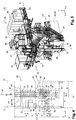
- the installation 1 further comprises a machine 15 for operating the oven 3, as illustrated in FIG. figure 2 .
- the machine 15 comprises a crane 16 having two beams 17 which extend transversely and which are spaced - along the axis X - by a longitudinal distance D.
- the crane 16 is designed to move in the longitudinal direction X to above the cells 8.
- the beams 17 of the crane 16 are mounted longitudinally movable on longitudinal rails 11, 12 each formed in the vicinity of one of the two transverse walls 13, 14 of transverse end of the building 2.
- the machine 15 further comprises a carriage 20 which is mounted transversely movable on the two beams 17 of the traveling crane 16.
- the carriage 20 is thus designed to move in the transverse direction Y above the cells 8.
- a suction pump 35 for example of the cyclone type.
- a cooling device 36 for example of the cyclone type.
- a suction hopper 37 for example of the cyclone type.
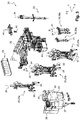
- the carriage 20 further comprises a lifting device 41 comprising a hook 42, for example a hoist of high capacity, intended in particular for the handling of the heating partitions 7, and a hopper 43 for storing dust having a substantially vertical axis 44
- the carriage 20 also comprises an electrical room 45 or an electrical cabinet.
- the carriage 20 has a median longitudinal plane P, which extends parallel to the X and Z axes, as shown in FIGS. Figures 3 to 5 , especially.
- the carriage 20 has a longitudinal dimension Lx and a transverse dimension Ly which, if the platform 22 is rectangular, can typically correspond respectively to the length and width of the platform 22.
- the carriage 20 in order to optimize the arrangement of the carriage 20, it is intended to place some of the tools intended to be introduced into the cells 8, and preferably all the tools intended to be introduced into the cells 8, so as to centered in relation to the median longitudinal plane P.
- the tools or apparatus which are not intended to be introduced into the cells 8 need not be centered and can therefore be arranged at another location of the carriage 20, so as not to unnecessarily encumber the vicinity of the median longitudinal plane P.
- central corridor 50 which has the shape of a parallelepiped having lateral faces 46, 47 vertical and longitudinal, parallel to the median longitudinal plane P, which is centered on the plane P, and which has a transverse dimension substantially equal to the spacing d of the cells 8.
- a substantially longitudinal central zone 51 which includes the central corridor 50 and which is arranged substantially symmetrically with respect to the median longitudinal plane P of the carriage 20.
- the transverse dimension of the central zone is equal to N times the transverse dimension of the central corridor 50, N being between 1.4 and 2, preferably between 1.4 and 1.7, for example of the order of 1.5.
- the central zone 51 has the shape of a parallelepiped having lateral faces 48, 49 vertical and longitudinal, parallel to the median longitudinal plane P, and situated on either side of the lateral faces 46, 47 of the central corridor 50.
- some of the tools, and preferably all the tools, intended to be introduced into the cells 8 have their vertical axis included in the central zone 51, and preferably in the central corridor 50.
- some of the tools, and preferably all the tools, intended to be introduced into the cells 8 are included in the central zone 51.
- the carriage 20 comprises a first and a second clamp 23, that is to say a double clamp, and a first and a second filling pipe 30 in dust, that is to say a double filling duct.
- the vertical axes 24 of the clamps 23 are arranged substantially symmetrically with respect to the median longitudinal plane P of the carriage 20. In other words, since the vertical axes 24 are spaced, in the transverse direction Y, by a distance B substantially equal to the center distance d of the cells 8 and that the central corridor 50 has a width d, the vertical axes 24 of the clamps 23 are each included in a lateral face 46, 47 of the central corridor 50.
- the vertical axes 31 of the dust filling pipes 30 are arranged substantially symmetrically with respect to the median longitudinal plane P of the carriage 20.
- the vertical axes 31 are spaced, in the transverse direction Y, a distance B substantially equal to the center distance d of the cells 8 and that the central corridor 44 has a width d, the vertical axes 31 of the filling pipes 30 in dust are each included in a lateral face 46, 47 of the central corridor 50.
- the axes 24, 31 of the clamps 23 and the filling pipes 30 in dust, respectively, are therefore two by two located in the same plane (X, Z).
- the carriage 20 comprises a single suction pipe 33 of the dust contained in a cell 8.
- the vertical axis 34 of the suction pipe 33 is located in the central zone 51, and preferably in the central corridor 50.
- the suction pipe 33 is located in its entirety in the central zone 51.
- the vertical axis 34 of the suction pipe 33 may be located substantially in the same plane (X, Z) as a vertical axis 24 of a clamp - or a vertical axis 31 of a filling pipe 30.
- the hook 42 of the lifting device 41 can also be arranged in the central zone 51, and preferably in the central corridor 50.
- the lifting device 41 is arranged at a longitudinal end of the carriage 20. Furthermore, it is possible to provide the electrical room 45 or the electrical cabinet at the other longitudinal end of the carriage 20, possibly substantially transversely centered.
- the dust storage hopper 43 is also advantageously arranged substantially centrally. More precisely, the vertical axis 44 of the hopper 43 may be located in the central zone 51, and preferably in the central corridor 50, for example in a lateral face 46, 47 of the central corridor 50.
- the cockpit 40 is preferably arranged substantially in the central zone 51. It comprises a seat 52, for the operator, which can rotate about a substantially vertical axis.
- the seat 52 can be oriented to face a transverse vertical plane, in the direction of the clamps 23, at least during the gripping operations of the anodes 10, raw or cooked.
- the devices carried by the carriage 20 which are not intended to be introduced into a cavity 8 are advantageously arranged on the carriage 20 out the central corridor 50, and preferably outside the central zone 51.
- these devices can be arranged on the carriage 20 on the same side of the central corridor 50, or the central zone 51.
- the suction pump 35, the cooling device 36, the suction hopper 37 and the filter 38 are arranged on the carriage 20 on the same side of the central corridor 50.
- the various tools or elements of the carriage 20 may be arranged in the following order: the clamps 23, the cockpit 40, the filling ducts 30 in dust, and the suction pipe 33 of the dust.
- the cockpit 40 being located between the clamps 23 and the filling ducts 30, and being equipped with a swivel seat, it allows the operator excellent visibility on the operations carried out in the cells 8 during the gripping of the anodes 10 and when filling the cells 8 in dust, which are delicate operations and must be conducted with precision.
- the invention makes it possible to reduce at least one of the dimensions of the carriage 20.
- the known carriages may have a transverse dimension of the order of 8550 mm.
- the longitudinal dimension Lx of the carriage 20 can be unchanged, for example of the order of 13,600 mm.
- a first advantage of the arrangement of the carriage 20 according to the invention lies in the optimization of the operation of the oven 3 without negative impact on the dimensions of the installation 1.
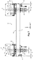
- Figures 8 and 9 represent the carriage 20 in an extreme position, near a transverse end wall 13 of the building 2.
- each of the doubled tools can have access to all the cells 8 of the furnace 3, as illustrated on the figure 8 .
- figure 9 represents the carriage 20 in extreme position near an end wall 13 of a building 2 according to the invention.
- a carriage 20 'of the prior art having a dimension transverse greater than the carriage 20 according to the invention
- the end wall 13 'of the building 2' of the prior art receiving the carriage 20 '.
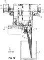
- a second advantage of the invention is to allow, by rationalizing the arrangement of the various tools and apparatus on the carriage 20, to provide the operator present in the cockpit 40 a better visibility during the various operations he leads.
- the figures 11 and 12 show clearly that, thanks to the invention, the operator has visibility to the bottom of the cell 8 concerned, without having to leave his seat, and in particular to get up.
- the invention provides a decisive improvement to the prior art, by providing a carriage that carries some tools in duplicate, for reasons of redundancy and cadence, which guarantees the access of each of these tools to all the cells. oven, and without degrading the visibility of the operator to the cells or increase the size of the truck. Due to the optimized arrangement of the various tools and devices on the carriage, the invention also makes it possible to considerably improve the arrangement of the carriage without requiring the implementation of numerous additional conduits interconnecting these tools and devices, which would complicate and weigh down the truck structure, and require more maintenance.
Landscapes
- Engineering & Computer Science (AREA)
- Mechanical Engineering (AREA)
- General Engineering & Computer Science (AREA)
- Chemical & Material Sciences (AREA)
- Chemical Kinetics & Catalysis (AREA)
- Electrochemistry (AREA)
- Materials Engineering (AREA)
- Metallurgy (AREA)
- Organic Chemistry (AREA)
- Electrolytic Production Of Metals (AREA)
- Handcart (AREA)
Claims (17)
- Wagen zum Betrieb eines Ofens (3) in einer Anlage (1) zur Befeuerung bzw. zum Brennen von Anoden (10) für die Aluminiumelektrolyse, wobei der Ofen (3) eine Mehrzahl von Zellen (8) umfasst, die sich jeweils im Wesentlichen in einer Längsrichtung (X) erstrecken und in einer Querrichtung (Y) nebeneinander angeordnet sind, wobei der Achsabstand (d) der Zellen (8) - der als der Querabstand zwischen den Mittellängsebenen zweier benachbarter Zellen (8) definiert ist - im Wesentlichen konstant ist, wobei der Wagen (20) dazu ausgelegt ist, sich in der Querrichtung (Y) über die Zellen (8) zu bewegen, und eine Mittellängsebene (P) aufweist, wobei der Wagen (20) zumindest ein erstes und ein zweites Werkzeug (23, 30) eines selben ersten Typs aufweist, die dazu angeordnet sind, jeweils in eine Zelle (8) eingeführt zu werden, um eine selbe erste Funktion zu erfüllen, und jeweils eine im Wesentlichen vertikale Achse (24, 31) aufweisen, wobei die vertikalen Achsen (24, 31) des ersten und zweiten Werkzeugs (23, 30) des ersten Typs in der Querrichtung (Y) um einen Abstand (B), der im Wesentlichen gleich dem Achsabstand (d) der Zellen (8) ist, beabstandet sind, dadurch gekennzeichnet, dass die vertikalen Achsen (24, 31) des ersten und zweiten Werkzeugs (23, 30) des ersten Typs im Wesentlichen symmetrisch zur Mittellängsebene (P) des Wagens (20) angeordnet sind, wobei die vertikalen Achsen (24, 31) der Werkzeuge (23, 30) zwischeneinander einen im Wesentlichen längs verlaufenden Mittelgang (50) auf dem Wagen (20) definieren, dass der Wagen einen im Wesentlichen längs verlaufenden Mittelbereich (51) aufweist, der den Mittelgang (50) einschließt und im Wesentlichen symmetrisch zur Mittellängsebene (P) des Wagens (20) angeordnet ist, wobei die Querabmessung des Mittelbereichs gleich dem N-fachen der Querabmessung des Mittelgangs (50) ist, wobei N zwischen 1,4 und 2, vorzugsweise zwischen 1,4 und 1,7, beispielsweise etwa 1,5, beträgt, und dass der Wagen mehrere Zusatzwerkzeuge (23, 30, 33) anderer Typen umfasst, die dazu angeordnet sind, jeweils in eine Zelle (8) eingeführt zu werden, um andere Funktionen zu erfüllen, und jeweils eine im Wesentlichen vertikale Achse (24, 31, 34) umfassen, wobei jedes dieser Zusatzwerkzeuge anderer Typen so auf dem Wagen (20) angeordnet ist, dass sich seine vertikale Achse im Mittelbereich (51) und vorzugsweise im Mittelgang (50) befindet.
- Wagen nach Anspruch 1, dadurch gekennzeichnet, dass die Zusatzwerkzeuge zumindest ein erstes und ein zweites Werkzeug (23, 30) eines selben, sich vom ersten Typ unterscheidenden zweiten Typs umfassen, die dazu angeordnet sind, jeweils in eine Zelle (8) eingeführt zu werden, um eine selbe, sich von der ersten Funktion unterscheidende zweite Funktion zu erfüllen, wobei die vertikalen Achsen (24, 31) des ersten und zweiten Werkzeugs (23, 30) des zweiten Typs in der Querrichtung (Y) um einen Abstand (B), der im Wesentlichen gleich dem Achsabstand (d) der Zellen (8) ist, beabstandet sind, wobei das erste und zweite Werkzeug (23, 30) des zweiten Typs zudem im Wesentlichen symmetrisch zur Mittellängsebene (P) des Wagens (20) angeordnet sind.
- Wagen nach Anspruch 1 oder Anspruch 2, dadurch gekennzeichnet, dass die Werkzeuge, die auf dem Wagen (20) angebracht und dazu bestimmt sind, in eine Zelle (8) eingeführt zu werden, zu der Folgendes umfassenden Gruppe gehören: eine Zange (23) zum Greifen der Anoden (10), eine Leitung (30) zum Befüllen der Zellen (8) mit Grus, ein Rohr (33) zum Absaugen des in einer Zelle (8) enthaltenen Gruses.
- Wagen nach Anspruch 3, dadurch gekennzeichnet, dass er zumindest zwei Greifzangen (23) und/oder zumindest zwei Befüllleitungen (30) umfasst.
- Wagen nach einem der Ansprüche 1 bis 4, dadurch gekennzeichnet, dass er ein einziges Rohr (33) zum Absaugen des in einer Zelle (8) enthaltenen Gruses umfasst, wobei das Saugrohr (33) eine im Wesentlichen vertikale Achse (34) aufweist, die sich im Wesentlichen in derselben vertikalen Längsebene wie die vertikale Achse (24, 31) eines der Werkzeuge (23, 30) des ersten Typs befindet.
- Wagen nach einem der Ansprüche 1 bis 5, dadurch gekennzeichnet, dass er ferner eine Hubvorrichtung (41) umfasst, die einen Haken (42) aufweist, wobei der Haken (42) im Mittelbereich (51) und vorzugsweise im Mittelgang (50) angeordnet ist.
- Wagen nach einem der Ansprüche 1 bis 6, dadurch gekennzeichnet, dass er ferner einen Trichter (43) zur Aufbewahrung von Grus mit einer im Wesentlichen vertikalen Achse (44) umfasst, wobei sich diese Achse (44) im Mittelbereich (51) und vorzugsweise im Mittelgang (50) befindet.
- Wagen nach einem der Ansprüche 1 bis 7, dadurch gekennzeichnet, dass er ferner einen auf dem Wagen (20) in einer zur Mittellängsebene (P) des Wagens (20) im Wesentlichen zentrierten Weise angeordneten Steuerstand (40) umfasst, wobei der Steuerstand (40) vorzugsweise im Wesentlichen im Mittelbereich (51) angeordnet ist.
- Wagen nach Anspruch 8, dadurch gekennzeichnet, dass der Steuerstand (40) in der Längsrichtung (X) zwischen einer oder mehreren Leitungen (30) zum Befüllen der Zellen (8) mit Grus und einer oder mehreren Zangen (23) zum Greifen der Anoden (10) angeordnet ist.
- Wagen nach Anspruch 8 oder 9, dadurch gekennzeichnet, dass der Steuerstand (40) einen Sitz (52) umfasst, der um eine im Wesentlichen vertikale Achse schwenkbar ist, wobei der Sitz (52) so ausgerichtet werden kann, dass er zumindest bei der Ausführung des der Funktion des Werkzeugs (23) entsprechenden Vorgangs einer vertikalen Querebene in Richtung eines der Werkzeuge (23) gegenüberliegt.
- Wagen nach einem der Ansprüche 1 bis 10, dadurch gekennzeichnet, dass er ferner Geräte (35 - 38) umfasst, die dazu vorgesehen sind, die Funktion der Werkzeuge (23, 30) zu ermöglichen, jedoch nicht in eine der Zelle (8) eingeführt zu werden, wobei diese Geräte (35 - 38) auf dem Wagen (20) außerhalb des Mittelgangs (50) und vorzugsweise außerhalb des Mittelbereichs (51) angeordnet sind.
- Wagen nach Anspruch 11, dadurch gekennzeichnet, dass die Geräte (35-38) auf dem Wagen (20) auf einer selben Seite des Mittelgangs (50) oder des Mittelbereichs (51) angeordnet sind.
- Wagen nach Anspruch 11 der 12, dadurch gekennzeichnet, dass die Geräte zu der Folgendes umfassenden Gruppe gehören: eine Pumpe (35), eine Kühlvorrichtung (36), ein Saugtrichter (37), ein Filter (38).
- Maschine zum Betrieb eines Ofens (3) in einer Anlage (1) zur Befeuerung bzw. zum Brennen von Anoden (10) für die Aluminiumelektrolyse, wobei der Ofen (3) eine Mehrzahl von Kammern (4) umfasst, die sich in einer Querrichtung (Y) erstrecken und nebeneinander in einer Längsrichtung (X) angeordnet sind, wobei jede Kammer (4) eine Mehrzahl von Zellen (8) aufweist, die sich jeweils im Wesentlichen in der Längsrichtung (X) erstrecken und in der Querrichtung (Y) nebeneinander angeordnet sind, wobei die Maschine (15) Folgendes umfasst:- einen Laufkran (16), der zwei sich quer erstreckende Träger (17) aufweist und dazu ausgelegt ist, sich in der Längsrichtung über die Zellen (8) zu bewegen;- einen Wagen (20) nach einem der Ansprüche 1 bis 13, wobei der Wagen (20) quer bewegbar an den beiden Trägern (17) des Laufkrans (16) angebracht ist.
- Maschine nach Anspruch 14, dadurch gekennzeichnet, dass der Längsabstand zwischen den beiden Trägern (17) des Laufkrans (16) definiert ist durch:
 F das halbe Maß einer auf dem Wagen (20) angebrachten Zange (23) zum Greifen der Anoden (10) ist;H die Abmessung eines auf dem Wagen (20) angebrachten Steuerstands (40) ist;J die Abmessung einer auf dem Wagen (20) angebrachten Leitung (30) zum Befüllen der Zellen (8) mit Grus ist;L die Abmessung eines auf dem Wagen (20) angebrachten Rohrs (33) zum Absaugen des in einer Zelle (8) enthaltenen Gruses ist;E, G, I, K, M jeweils funktionelle Spiele zwischen einem Träger (17) und der benachbarten Greifzange (23), der Greifzange (23) und dem Steuerstand (40), dem Steuerstand (40) und der Befüllleitung (30), der Befüllleitung (30) und dem Saugrohr (33) bzw. dem Saugrohr (33) und dem benachbarten Träger (17) sind.
 - Anodenbefeuerungs- bzw. Anodenbrennanlage (10) für die Aluminiumelektrolyse, umfassend :- ein Gebäude (2), in dem sich ein Ofen (3) zur Befeuerung bzw. zum Brennen von Anoden befindet, wobei der Ofen (3) eine Mehrzahl von Kammern (4) umfasst, die sich in einer Querrichtung (Y) erstrecken und in einer Längsrichtung (X) nebeneinander angeordnet sind, wobei jede Kammer (4) eine Mehrzahl von Zellen (8) aufweist, die sich jeweils im Wesentlichen in der Längsrichtung (X) erstrecken und in der Querrichtung (Y) nebeneinander angeordnet sind;- eine Maschine (15) nach Anspruch 14 oder 15, wobei der Laufkran (16) längs beweglich auf Längsschienen (11, 12), die in der Nähe zweier quer verlaufender Außenwände (13, 14) des Gebäudes (2) vorgesehen sind, angebracht ist.
- Anlage nach Anspruch 16, dadurch gekennzeichnet, dass die Querabmessung des Wagens (20) definiert ist durch: Ly = 2A - B + 2C,
wobei in der Querrichtung:A der Zellennäherungsabstand, d. h. der Abstand zwischen einer Längsschiene (11, 12) und der Mittellängsebene der zur Schiene (11, 12) benachbarten Außenzelle (8), ist;B der Abstand zwischen den vertikalen Achsen (24, 31) des ersten und zweiten Werkzeugs (23, 30) des ersten Typs ist, der im Wesentlichen gleich dem Achsabstand (d) der Zellen (8) ist;C die zulässige Überschreitung, d. h. der Abstand zwischen einer Längsschiene (11, 12) und der jeweiligen quer verlaufenden Außenwand (13, 14) des Gebäudes (2), ist.
Applications Claiming Priority (2)
| Application Number | Priority Date | Filing Date | Title |
|---|---|---|---|
| FR1302964A FR3014911B1 (fr) | 2013-12-17 | 2013-12-17 | Chariot et machine pour l'exploitation d'un four dans une installation de cuisson d'anodes |
| PCT/FR2014/000282 WO2015092162A1 (fr) | 2013-12-17 | 2014-12-12 | Chariot et machine pour l'exploitation d'un four dans une installation de cuisson d'anodes |
Publications (2)
| Publication Number | Publication Date |
|---|---|
| EP3084331A1 EP3084331A1 (de) | 2016-10-26 |
| EP3084331B1 true EP3084331B1 (de) | 2018-02-21 |
Family
ID=50721827
Family Applications (1)
| Application Number | Title | Priority Date | Filing Date |
|---|---|---|---|
| EP14828179.3A Active EP3084331B1 (de) | 2013-12-17 | 2014-12-12 | Wagen und maschine zum betrieb eines ofens in einer anodenbefeuerungsanlage |
Country Status (7)
| Country | Link |
|---|---|
| EP (1) | EP3084331B1 (de) |
| CN (1) | CN105874292B (de) |
| AR (1) | AR098769A1 (de) |
| CA (1) | CA2932684C (de) |
| FR (1) | FR3014911B1 (de) |
| RU (1) | RU2685611C1 (de) |
| WO (1) | WO2015092162A1 (de) |
Families Citing this family (2)
| Publication number | Priority date | Publication date | Assignee | Title |
|---|---|---|---|---|
| EP4293141A1 (de) * | 2022-06-13 | 2023-12-20 | Dubai Aluminium PJSC | Anodenwartungsanordnung für eine aluminium-elektrolyseanlage und verfahren zum betreiben dafür |
| CN120350419B (zh) * | 2025-06-20 | 2025-09-09 | 安徽舜富精密科技股份有限公司 | 一种铝合金表面快速氧化装置 |
Family Cites Families (9)
| Publication number | Priority date | Publication date | Assignee | Title |
|---|---|---|---|---|
| JPS5220488Y2 (de) * | 1971-02-10 | 1977-05-12 | ||
| US4394242A (en) * | 1980-01-28 | 1983-07-19 | Adnovum Ag | Clamp, tool, and electrolysis cell anode mount |
| SU1148905A1 (ru) * | 1983-12-20 | 1985-04-07 | Красноярский Политехнический Институт | Мостовой кран дл обслуживани алюминиевых электролизеров |
| ATA121992A (de) * | 1992-06-15 | 1996-08-15 | Wienerberger Ziegelind | Verfahren zum trocknen und/oder brennen von ziegelrohlingen |
| FR2890661B1 (fr) * | 2005-09-12 | 2007-11-09 | Ecl Soc Par Actions Simplifiee | Reservoir de poussier utilise pour la cuisson d'anodes, installation de cuisson d'anodes et procede de mise en place d'anodes dans un four |
| DE102008030872A1 (de) * | 2008-06-30 | 2009-12-31 | Wilkening, Siegfried, Dr.-Ing. | Verfahren und Vorrichtung zum Brennen von grünen Kohlenstoffkörpern |
| FR2937341B1 (fr) * | 2008-10-16 | 2010-11-12 | Ecl | Machine de service utilisee pour intervenir sur les cellules d'electrolyse de production d'aluminium par electrolyse ignee |
| CN201367466Y (zh) * | 2009-01-08 | 2009-12-23 | 贵阳铝镁设计研究院 | 一种电解槽大修车间的分区配置结构 |
| CN201520804U (zh) * | 2009-11-05 | 2010-07-07 | 贵阳铝镁设计研究院 | 一种电解多功能机组上的工具小车配置结构 |
-
2013
- 2013-12-17 FR FR1302964A patent/FR3014911B1/fr not_active Expired - Fee Related
-
2014
- 2014-12-12 CN CN201480068038.0A patent/CN105874292B/zh active Active
- 2014-12-12 RU RU2016129016A patent/RU2685611C1/ru active
- 2014-12-12 EP EP14828179.3A patent/EP3084331B1/de active Active
- 2014-12-12 CA CA2932684A patent/CA2932684C/fr active Active
- 2014-12-12 WO PCT/FR2014/000282 patent/WO2015092162A1/fr not_active Ceased
- 2014-12-16 AR ARP140104679A patent/AR098769A1/es unknown
Also Published As
| Publication number | Publication date |
|---|---|
| CA2932684A1 (fr) | 2015-06-25 |
| AR098769A1 (es) | 2016-06-15 |
| EP3084331A1 (de) | 2016-10-26 |
| CN105874292A (zh) | 2016-08-17 |
| FR3014911B1 (fr) | 2016-01-01 |
| CA2932684C (fr) | 2021-09-14 |
| RU2685611C1 (ru) | 2019-04-22 |
| CN105874292B (zh) | 2019-04-26 |
| RU2016129016A (ru) | 2018-01-23 |
| FR3014911A1 (fr) | 2015-06-19 |
| WO2015092162A1 (fr) | 2015-06-25 |
Similar Documents
| Publication | Publication Date | Title |
|---|---|---|
| US10493525B2 (en) | Lifting and removal device for additive manufacturing system | |
| WO2016128661A1 (fr) | Unité pour l'exploitation d'une installation de production d'aluminium, installation de production d'aluminium et procédé d'exploitation d'une telle installation | |
| CA2932684C (fr) | Chariot et machine pour l'exploitation d'un four dans une installation de cuisson d'anodes | |
| CA2560675C (fr) | Module de service compact destine aux usines de production d'aluminium par electrolyse | |
| CA2935439A1 (fr) | Cuve d'electrolyse comportant un dispositif de levage d'ensembles anodiques | |
| CA2938716C (fr) | Systeme pour la realisation d'operations liees a l'exploitation de cellules d'une installation de production d'aluminium par electrolyse | |
| WO2016128634A1 (fr) | Unité pour l'exploitation d'une installation de production d'aluminium | |
| EP3099843B1 (de) | Vorrichtung zur speicherung einer last über einer elektrolysezelle | |
| WO2016174313A1 (fr) | Dispositif de manutention d'un équipement d'une cellule d'électrolyse | |
| FR2509701A1 (fr) | Dispositif de reprise, de transport et d'evacuation dans un dispositif de refroidissement pour corps moules plastiques, en particulier pour anodes en carbone | |
| WO2011098701A1 (fr) | Procede de montage, de transport et de stockage d'un ouvrant | |
| CA2935478C (fr) | Systeme de capotage pour cuve d'electrolyse | |
| EP2761061B1 (de) | Kompaktes dienstmodul und seine verwendung in einer anlage zur herstellung von aluminium durch elektrolyse | |
| FR2940796A1 (fr) | Dispositif d'attache de recipient pour collecter des debris solides et pivotant a l'extremite d'un bras mobile, en particulier dispositif d'attache des godets articules d'une pelle a croute | |
| CA2620111A1 (fr) | Dispositif de remplissage de poussier, installation de cuisson d'anodes et procede de mise en place d'anodes dans un four | |
| FR3032456B1 (fr) | Machine de service pour l'exploitation d'une installation de production d'aluminium | |
| FR3032457A1 (fr) | Module de service pour l'exploitation d'une installation de production d'aluminium | |
| FR3032461A1 (fr) | Procede pour desengager un ensemble anodique use d'une cuve d'une installation de production d'aluminium | |
| CA3131081A1 (fr) | Dispositif de manutention destine a convoyer un outil d'intervention sur une cuve d'electrolyse | |
| CA3131450A1 (fr) | Outil d'intervention pour l'exploitation d'une cuve d'electrolyse | |
| OA17345A (fr) | Dispositif extracteur de cales de courtcircuitage destiné à la mise en circuit d'une cellule d'électrolyse pour la production d'aluminium. | |
| OA16284A (fr) | Dispositif permettant d'extraire des cales de court-circuitage lors de la mise en circuit d'une cellule d'électrolyse pour la production d'aluminium. |
Legal Events
| Date | Code | Title | Description |
|---|---|---|---|
| PUAI | Public reference made under article 153(3) epc to a published international application that has entered the european phase |
Free format text: ORIGINAL CODE: 0009012 |
|
| 17P | Request for examination filed |
Effective date: 20160617 |
|
| AK | Designated contracting states |
Kind code of ref document: A1 Designated state(s): AL AT BE BG CH CY CZ DE DK EE ES FI FR GB GR HR HU IE IS IT LI LT LU LV MC MK MT NL NO PL PT RO RS SE SI SK SM TR |
|
| AX | Request for extension of the european patent |
Extension state: BA ME |
|
| DAX | Request for extension of the european patent (deleted) | ||
| REG | Reference to a national code |
Ref country code: DE Ref legal event code: R079 Ref document number: 602014021432 Country of ref document: DE Free format text: PREVIOUS MAIN CLASS: F27B0013020000 Ipc: F27B0009020000 |
|
| GRAP | Despatch of communication of intention to grant a patent |
Free format text: ORIGINAL CODE: EPIDOSNIGR1 |
|
| STAA | Information on the status of an ep patent application or granted ep patent |
Free format text: STATUS: GRANT OF PATENT IS INTENDED |
|
| RIC1 | Information provided on ipc code assigned before grant |
Ipc: F27D 3/06 20060101ALI20170724BHEP Ipc: F27B 9/26 20060101ALI20170724BHEP Ipc: F27B 13/06 20060101ALI20170724BHEP Ipc: F27D 3/12 20060101ALI20170724BHEP Ipc: C25C 3/12 20060101ALI20170724BHEP Ipc: B66C 17/06 20060101ALI20170724BHEP Ipc: F27B 9/02 20060101AFI20170724BHEP |
|
| INTG | Intention to grant announced |
Effective date: 20170817 |
|
| GRAJ | Information related to disapproval of communication of intention to grant by the applicant or resumption of examination proceedings by the epo deleted |
Free format text: ORIGINAL CODE: EPIDOSDIGR1 |
|
| STAA | Information on the status of an ep patent application or granted ep patent |
Free format text: STATUS: REQUEST FOR EXAMINATION WAS MADE |
|
| GRAS | Grant fee paid |
Free format text: ORIGINAL CODE: EPIDOSNIGR3 |
|
| STAA | Information on the status of an ep patent application or granted ep patent |
Free format text: STATUS: GRANT OF PATENT IS INTENDED |
|
| GRAP | Despatch of communication of intention to grant a patent |
Free format text: ORIGINAL CODE: EPIDOSNIGR1 |
|
| INTC | Intention to grant announced (deleted) | ||
| INTG | Intention to grant announced |
Effective date: 20171215 |
|
| GRAA | (expected) grant |
Free format text: ORIGINAL CODE: 0009210 |
|
| STAA | Information on the status of an ep patent application or granted ep patent |
Free format text: STATUS: THE PATENT HAS BEEN GRANTED |
|
| AK | Designated contracting states |
Kind code of ref document: B1 Designated state(s): AL AT BE BG CH CY CZ DE DK EE ES FI FR GB GR HR HU IE IS IT LI LT LU LV MC MK MT NL NO PL PT RO RS SE SI SK SM TR |
|
| REG | Reference to a national code |
Ref country code: GB Ref legal event code: FG4D Free format text: NOT ENGLISH |
|
| REG | Reference to a national code |
Ref country code: CH Ref legal event code: EP |
|
| REG | Reference to a national code |
Ref country code: AT Ref legal event code: REF Ref document number: 972216 Country of ref document: AT Kind code of ref document: T Effective date: 20180315 |
|
| REG | Reference to a national code |
Ref country code: IE Ref legal event code: FG4D Free format text: LANGUAGE OF EP DOCUMENT: FRENCH |
|
| REG | Reference to a national code |
Ref country code: DE Ref legal event code: R096 Ref document number: 602014021432 Country of ref document: DE |
|
| REG | Reference to a national code |
Ref country code: NL Ref legal event code: FP |
|
| REG | Reference to a national code |
Ref country code: LT Ref legal event code: MG4D |
|
| REG | Reference to a national code |
Ref country code: AT Ref legal event code: MK05 Ref document number: 972216 Country of ref document: AT Kind code of ref document: T Effective date: 20180221 |
|
| PG25 | Lapsed in a contracting state [announced via postgrant information from national office to epo] |
Ref country code: NO Free format text: LAPSE BECAUSE OF FAILURE TO SUBMIT A TRANSLATION OF THE DESCRIPTION OR TO PAY THE FEE WITHIN THE PRESCRIBED TIME-LIMIT Effective date: 20180521 Ref country code: FI Free format text: LAPSE BECAUSE OF FAILURE TO SUBMIT A TRANSLATION OF THE DESCRIPTION OR TO PAY THE FEE WITHIN THE PRESCRIBED TIME-LIMIT Effective date: 20180221 Ref country code: LT Free format text: LAPSE BECAUSE OF FAILURE TO SUBMIT A TRANSLATION OF THE DESCRIPTION OR TO PAY THE FEE WITHIN THE PRESCRIBED TIME-LIMIT Effective date: 20180221 Ref country code: CY Free format text: LAPSE BECAUSE OF FAILURE TO SUBMIT A TRANSLATION OF THE DESCRIPTION OR TO PAY THE FEE WITHIN THE PRESCRIBED TIME-LIMIT Effective date: 20180221 Ref country code: ES Free format text: LAPSE BECAUSE OF FAILURE TO SUBMIT A TRANSLATION OF THE DESCRIPTION OR TO PAY THE FEE WITHIN THE PRESCRIBED TIME-LIMIT Effective date: 20180221 Ref country code: HR Free format text: LAPSE BECAUSE OF FAILURE TO SUBMIT A TRANSLATION OF THE DESCRIPTION OR TO PAY THE FEE WITHIN THE PRESCRIBED TIME-LIMIT Effective date: 20180221 |
|
| PG25 | Lapsed in a contracting state [announced via postgrant information from national office to epo] |
Ref country code: BG Free format text: LAPSE BECAUSE OF FAILURE TO SUBMIT A TRANSLATION OF THE DESCRIPTION OR TO PAY THE FEE WITHIN THE PRESCRIBED TIME-LIMIT Effective date: 20180521 Ref country code: RS Free format text: LAPSE BECAUSE OF FAILURE TO SUBMIT A TRANSLATION OF THE DESCRIPTION OR TO PAY THE FEE WITHIN THE PRESCRIBED TIME-LIMIT Effective date: 20180221 Ref country code: AT Free format text: LAPSE BECAUSE OF FAILURE TO SUBMIT A TRANSLATION OF THE DESCRIPTION OR TO PAY THE FEE WITHIN THE PRESCRIBED TIME-LIMIT Effective date: 20180221 Ref country code: LV Free format text: LAPSE BECAUSE OF FAILURE TO SUBMIT A TRANSLATION OF THE DESCRIPTION OR TO PAY THE FEE WITHIN THE PRESCRIBED TIME-LIMIT Effective date: 20180221 Ref country code: SE Free format text: LAPSE BECAUSE OF FAILURE TO SUBMIT A TRANSLATION OF THE DESCRIPTION OR TO PAY THE FEE WITHIN THE PRESCRIBED TIME-LIMIT Effective date: 20180221 Ref country code: GR Free format text: LAPSE BECAUSE OF FAILURE TO SUBMIT A TRANSLATION OF THE DESCRIPTION OR TO PAY THE FEE WITHIN THE PRESCRIBED TIME-LIMIT Effective date: 20180522 |
|
| PG25 | Lapsed in a contracting state [announced via postgrant information from national office to epo] |
Ref country code: MT Free format text: LAPSE BECAUSE OF FAILURE TO SUBMIT A TRANSLATION OF THE DESCRIPTION OR TO PAY THE FEE WITHIN THE PRESCRIBED TIME-LIMIT Effective date: 20180221 |
|
| PG25 | Lapsed in a contracting state [announced via postgrant information from national office to epo] |
Ref country code: PL Free format text: LAPSE BECAUSE OF FAILURE TO SUBMIT A TRANSLATION OF THE DESCRIPTION OR TO PAY THE FEE WITHIN THE PRESCRIBED TIME-LIMIT Effective date: 20180221 Ref country code: RO Free format text: LAPSE BECAUSE OF FAILURE TO SUBMIT A TRANSLATION OF THE DESCRIPTION OR TO PAY THE FEE WITHIN THE PRESCRIBED TIME-LIMIT Effective date: 20180221 Ref country code: IT Free format text: LAPSE BECAUSE OF FAILURE TO SUBMIT A TRANSLATION OF THE DESCRIPTION OR TO PAY THE FEE WITHIN THE PRESCRIBED TIME-LIMIT Effective date: 20180221 Ref country code: AL Free format text: LAPSE BECAUSE OF FAILURE TO SUBMIT A TRANSLATION OF THE DESCRIPTION OR TO PAY THE FEE WITHIN THE PRESCRIBED TIME-LIMIT Effective date: 20180221 Ref country code: EE Free format text: LAPSE BECAUSE OF FAILURE TO SUBMIT A TRANSLATION OF THE DESCRIPTION OR TO PAY THE FEE WITHIN THE PRESCRIBED TIME-LIMIT Effective date: 20180221 |
|
| REG | Reference to a national code |
Ref country code: DE Ref legal event code: R097 Ref document number: 602014021432 Country of ref document: DE |
|
| PG25 | Lapsed in a contracting state [announced via postgrant information from national office to epo] |
Ref country code: CZ Free format text: LAPSE BECAUSE OF FAILURE TO SUBMIT A TRANSLATION OF THE DESCRIPTION OR TO PAY THE FEE WITHIN THE PRESCRIBED TIME-LIMIT Effective date: 20180221 Ref country code: SK Free format text: LAPSE BECAUSE OF FAILURE TO SUBMIT A TRANSLATION OF THE DESCRIPTION OR TO PAY THE FEE WITHIN THE PRESCRIBED TIME-LIMIT Effective date: 20180221 Ref country code: SM Free format text: LAPSE BECAUSE OF FAILURE TO SUBMIT A TRANSLATION OF THE DESCRIPTION OR TO PAY THE FEE WITHIN THE PRESCRIBED TIME-LIMIT Effective date: 20180221 Ref country code: DK Free format text: LAPSE BECAUSE OF FAILURE TO SUBMIT A TRANSLATION OF THE DESCRIPTION OR TO PAY THE FEE WITHIN THE PRESCRIBED TIME-LIMIT Effective date: 20180221 |
|
| PLBE | No opposition filed within time limit |
Free format text: ORIGINAL CODE: 0009261 |
|
| STAA | Information on the status of an ep patent application or granted ep patent |
Free format text: STATUS: NO OPPOSITION FILED WITHIN TIME LIMIT |
|
| 26N | No opposition filed |
Effective date: 20181122 |
|
| PG25 | Lapsed in a contracting state [announced via postgrant information from national office to epo] |
Ref country code: SI Free format text: LAPSE BECAUSE OF FAILURE TO SUBMIT A TRANSLATION OF THE DESCRIPTION OR TO PAY THE FEE WITHIN THE PRESCRIBED TIME-LIMIT Effective date: 20180221 |
|
| GBPC | Gb: european patent ceased through non-payment of renewal fee |
Effective date: 20181212 |
|
| PG25 | Lapsed in a contracting state [announced via postgrant information from national office to epo] |
Ref country code: MC Free format text: LAPSE BECAUSE OF FAILURE TO SUBMIT A TRANSLATION OF THE DESCRIPTION OR TO PAY THE FEE WITHIN THE PRESCRIBED TIME-LIMIT Effective date: 20180221 Ref country code: LU Free format text: LAPSE BECAUSE OF NON-PAYMENT OF DUE FEES Effective date: 20181212 |
|
| REG | Reference to a national code |
Ref country code: IE Ref legal event code: MM4A |
|
| REG | Reference to a national code |
Ref country code: BE Ref legal event code: MM Effective date: 20181231 |
|
| PG25 | Lapsed in a contracting state [announced via postgrant information from national office to epo] |
Ref country code: IE Free format text: LAPSE BECAUSE OF NON-PAYMENT OF DUE FEES Effective date: 20181212 |
|
| PG25 | Lapsed in a contracting state [announced via postgrant information from national office to epo] |
Ref country code: BE Free format text: LAPSE BECAUSE OF NON-PAYMENT OF DUE FEES Effective date: 20181231 |
|
| PG25 | Lapsed in a contracting state [announced via postgrant information from national office to epo] |
Ref country code: GB Free format text: LAPSE BECAUSE OF NON-PAYMENT OF DUE FEES Effective date: 20181212 |
|
| PG25 | Lapsed in a contracting state [announced via postgrant information from national office to epo] |
Ref country code: TR Free format text: LAPSE BECAUSE OF FAILURE TO SUBMIT A TRANSLATION OF THE DESCRIPTION OR TO PAY THE FEE WITHIN THE PRESCRIBED TIME-LIMIT Effective date: 20180221 |
|
| PG25 | Lapsed in a contracting state [announced via postgrant information from national office to epo] |
Ref country code: PT Free format text: LAPSE BECAUSE OF FAILURE TO SUBMIT A TRANSLATION OF THE DESCRIPTION OR TO PAY THE FEE WITHIN THE PRESCRIBED TIME-LIMIT Effective date: 20180221 |
|
| PG25 | Lapsed in a contracting state [announced via postgrant information from national office to epo] |
Ref country code: HU Free format text: LAPSE BECAUSE OF FAILURE TO SUBMIT A TRANSLATION OF THE DESCRIPTION OR TO PAY THE FEE WITHIN THE PRESCRIBED TIME-LIMIT; INVALID AB INITIO Effective date: 20141212 Ref country code: MK Free format text: LAPSE BECAUSE OF NON-PAYMENT OF DUE FEES Effective date: 20180221 |
|
| PG25 | Lapsed in a contracting state [announced via postgrant information from national office to epo] |
Ref country code: IS Free format text: LAPSE BECAUSE OF FAILURE TO SUBMIT A TRANSLATION OF THE DESCRIPTION OR TO PAY THE FEE WITHIN THE PRESCRIBED TIME-LIMIT Effective date: 20180621 |
|
| PGFP | Annual fee paid to national office [announced via postgrant information from national office to epo] |
Ref country code: NL Payment date: 20251119 Year of fee payment: 12 |
|
| REG | Reference to a national code |
Ref country code: CH Ref legal event code: U11 Free format text: ST27 STATUS EVENT CODE: U-0-0-U10-U11 (AS PROVIDED BY THE NATIONAL OFFICE) Effective date: 20260101 |
|
| PGFP | Annual fee paid to national office [announced via postgrant information from national office to epo] |
Ref country code: DE Payment date: 20251126 Year of fee payment: 12 |
|
| PGFP | Annual fee paid to national office [announced via postgrant information from national office to epo] |
Ref country code: FR Payment date: 20251120 Year of fee payment: 12 |
|
| PGFP | Annual fee paid to national office [announced via postgrant information from national office to epo] |
Ref country code: CH Payment date: 20260101 Year of fee payment: 12 |