EP3084187B1 - Dispositif de drainage de fluides pour un moteur d'aéronef - Google Patents
Dispositif de drainage de fluides pour un moteur d'aéronef Download PDFInfo
- Publication number
- EP3084187B1 EP3084187B1 EP14827837.7A EP14827837A EP3084187B1 EP 3084187 B1 EP3084187 B1 EP 3084187B1 EP 14827837 A EP14827837 A EP 14827837A EP 3084187 B1 EP3084187 B1 EP 3084187B1
- Authority
- EP
- European Patent Office
- Prior art keywords
- engine
- collector
- liquids
- fluids
- line
- Prior art date
- Legal status (The legal status is an assumption and is not a legal conclusion. Google has not performed a legal analysis and makes no representation as to the accuracy of the status listed.)
- Active
Links
- 238000005086 pumping Methods 0.000 claims description 41
- 239000007789 gas Substances 0.000 claims description 35
- 238000012544 monitoring process Methods 0.000 claims description 28
- 238000000034 method Methods 0.000 claims description 7
- 230000000740 bleeding effect Effects 0.000 claims description 3
- 239000000567 combustion gas Substances 0.000 claims description 2
- 239000007788 liquid Substances 0.000 claims 13
- 238000007599 discharging Methods 0.000 claims 2
- 230000002547 anomalous effect Effects 0.000 claims 1
- 230000001419 dependent effect Effects 0.000 claims 1
- 239000012530 fluid Substances 0.000 description 84
- 230000002159 abnormal effect Effects 0.000 description 9
- 239000000446 fuel Substances 0.000 description 9
- 238000012423 maintenance Methods 0.000 description 8
- 238000005070 sampling Methods 0.000 description 6
- 230000000007 visual effect Effects 0.000 description 5
- 230000004913 activation Effects 0.000 description 3
- 238000002485 combustion reaction Methods 0.000 description 3
- 238000007872 degassing Methods 0.000 description 3
- 230000006835 compression Effects 0.000 description 2
- 238000007906 compression Methods 0.000 description 2
- 238000007789 sealing Methods 0.000 description 2
- 238000005507 spraying Methods 0.000 description 2
- 230000005540 biological transmission Effects 0.000 description 1
- 230000015556 catabolic process Effects 0.000 description 1
- 238000004891 communication Methods 0.000 description 1
- 238000005516 engineering process Methods 0.000 description 1
- 239000002828 fuel tank Substances 0.000 description 1
- 239000003517 fume Substances 0.000 description 1
- 239000012535 impurity Substances 0.000 description 1
- 238000007689 inspection Methods 0.000 description 1
- 230000010354 integration Effects 0.000 description 1
- 230000014759 maintenance of location Effects 0.000 description 1
- 230000007257 malfunction Effects 0.000 description 1
- 238000012806 monitoring device Methods 0.000 description 1
- 239000003921 oil Substances 0.000 description 1
- 239000003973 paint Substances 0.000 description 1
- 230000000737 periodic effect Effects 0.000 description 1
- 230000002028 premature Effects 0.000 description 1
- 238000011084 recovery Methods 0.000 description 1
- 238000007665 sagging Methods 0.000 description 1
- 239000007921 spray Substances 0.000 description 1
- 230000001960 triggered effect Effects 0.000 description 1
- 238000011144 upstream manufacturing Methods 0.000 description 1
- 238000013022 venting Methods 0.000 description 1
- XLYOFNOQVPJJNP-UHFFFAOYSA-N water Substances O XLYOFNOQVPJJNP-UHFFFAOYSA-N 0.000 description 1
Images

Classifications
-
- F—MECHANICAL ENGINEERING; LIGHTING; HEATING; WEAPONS; BLASTING
- F02—COMBUSTION ENGINES; HOT-GAS OR COMBUSTION-PRODUCT ENGINE PLANTS
- F02C—GAS-TURBINE PLANTS; AIR INTAKES FOR JET-PROPULSION PLANTS; CONTROLLING FUEL SUPPLY IN AIR-BREATHING JET-PROPULSION PLANTS
- F02C7/00—Features, components parts, details or accessories, not provided for in, or of interest apart form groups F02C1/00 - F02C6/00; Air intakes for jet-propulsion plants
- F02C7/22—Fuel supply systems
- F02C7/232—Fuel valves; Draining valves or systems
-
- B—PERFORMING OPERATIONS; TRANSPORTING
- B64—AIRCRAFT; AVIATION; COSMONAUTICS
- B64C—AEROPLANES; HELICOPTERS
- B64C1/00—Fuselages; Constructional features common to fuselages, wings, stabilising surfaces or the like
- B64C1/14—Windows; Doors; Hatch covers or access panels; Surrounding frame structures; Canopies; Windscreens accessories therefor, e.g. pressure sensors, water deflectors, hinges, seals, handles, latches, windscreen wipers
- B64C1/1407—Doors; surrounding frames
- B64C1/1453—Drain masts
-
- B—PERFORMING OPERATIONS; TRANSPORTING
- B64—AIRCRAFT; AVIATION; COSMONAUTICS
- B64D—EQUIPMENT FOR FITTING IN OR TO AIRCRAFT; FLIGHT SUITS; PARACHUTES; ARRANGEMENT OR MOUNTING OF POWER PLANTS OR PROPULSION TRANSMISSIONS IN AIRCRAFT
- B64D45/00—Aircraft indicators or protectors not otherwise provided for
-
- F—MECHANICAL ENGINEERING; LIGHTING; HEATING; WEAPONS; BLASTING
- F01—MACHINES OR ENGINES IN GENERAL; ENGINE PLANTS IN GENERAL; STEAM ENGINES
- F01M—LUBRICATING OF MACHINES OR ENGINES IN GENERAL; LUBRICATING INTERNAL COMBUSTION ENGINES; CRANKCASE VENTILATING
- F01M11/00—Component parts, details or accessories, not provided for in, or of interest apart from, groups F01M1/00 - F01M9/00
- F01M11/04—Filling or draining lubricant of or from machines or engines
- F01M11/0458—Lubricant filling and draining
-
- F—MECHANICAL ENGINEERING; LIGHTING; HEATING; WEAPONS; BLASTING
- F02—COMBUSTION ENGINES; HOT-GAS OR COMBUSTION-PRODUCT ENGINE PLANTS
- F02C—GAS-TURBINE PLANTS; AIR INTAKES FOR JET-PROPULSION PLANTS; CONTROLLING FUEL SUPPLY IN AIR-BREATHING JET-PROPULSION PLANTS
- F02C9/00—Controlling gas-turbine plants; Controlling fuel supply in air- breathing jet-propulsion plants
- F02C9/26—Control of fuel supply
-
- B—PERFORMING OPERATIONS; TRANSPORTING
- B64—AIRCRAFT; AVIATION; COSMONAUTICS
- B64D—EQUIPMENT FOR FITTING IN OR TO AIRCRAFT; FLIGHT SUITS; PARACHUTES; ARRANGEMENT OR MOUNTING OF POWER PLANTS OR PROPULSION TRANSMISSIONS IN AIRCRAFT
- B64D37/00—Arrangements in connection with fuel supply for power plant
- B64D37/02—Tanks
- B64D37/14—Filling or emptying
- B64D37/20—Emptying systems
- B64D37/26—Jettisoning of fuel
-
- F—MECHANICAL ENGINEERING; LIGHTING; HEATING; WEAPONS; BLASTING
- F05—INDEXING SCHEMES RELATING TO ENGINES OR PUMPS IN VARIOUS SUBCLASSES OF CLASSES F01-F04
- F05D—INDEXING SCHEME FOR ASPECTS RELATING TO NON-POSITIVE-DISPLACEMENT MACHINES OR ENGINES, GAS-TURBINES OR JET-PROPULSION PLANTS
- F05D2220/00—Application
- F05D2220/30—Application in turbines
- F05D2220/32—Application in turbines in gas turbines
- F05D2220/329—Application in turbines in gas turbines in helicopters
-
- F—MECHANICAL ENGINEERING; LIGHTING; HEATING; WEAPONS; BLASTING
- F05—INDEXING SCHEMES RELATING TO ENGINES OR PUMPS IN VARIOUS SUBCLASSES OF CLASSES F01-F04
- F05D—INDEXING SCHEME FOR ASPECTS RELATING TO NON-POSITIVE-DISPLACEMENT MACHINES OR ENGINES, GAS-TURBINES OR JET-PROPULSION PLANTS
- F05D2260/00—Function
- F05D2260/60—Fluid transfer
- F05D2260/601—Fluid transfer using an ejector or a jet pump
-
- F—MECHANICAL ENGINEERING; LIGHTING; HEATING; WEAPONS; BLASTING
- F05—INDEXING SCHEMES RELATING TO ENGINES OR PUMPS IN VARIOUS SUBCLASSES OF CLASSES F01-F04
- F05D—INDEXING SCHEME FOR ASPECTS RELATING TO NON-POSITIVE-DISPLACEMENT MACHINES OR ENGINES, GAS-TURBINES OR JET-PROPULSION PLANTS
- F05D2260/00—Function
- F05D2260/60—Fluid transfer
- F05D2260/602—Drainage
-
- F—MECHANICAL ENGINEERING; LIGHTING; HEATING; WEAPONS; BLASTING
- F05—INDEXING SCHEMES RELATING TO ENGINES OR PUMPS IN VARIOUS SUBCLASSES OF CLASSES F01-F04
- F05D—INDEXING SCHEME FOR ASPECTS RELATING TO NON-POSITIVE-DISPLACEMENT MACHINES OR ENGINES, GAS-TURBINES OR JET-PROPULSION PLANTS
- F05D2270/00—Control
- F05D2270/80—Devices generating input signals, e.g. transducers, sensors, cameras or strain gauges
Definitions
- the present invention relates to a fluid drainage device for an aircraft engine, an aircraft engine comprising such a device, as well as a method for controlling this engine.
- the state of the art includes in particular the documents FR-A-1 597 209 , EP-A1-2 626 616 and US-A-3,623,053 .
- a tank return is provided for recovering these fluids, that is to say that at least one pipe is provided for conveying the fluids to the aircraft fuel tank.
- this technology has many disadvantages. Indeed, it requires the aircraft manufacturer to provide this tank return which is used to recover the various fluids drained from the engine. This technical constraint is accentuated by the fact that the flow rates and temperatures of these fluids can be high. Leaks can also be the consequence of failures known as "dormant". In addition, the oil that is recovered pollutes the fuel stored in the tank. The management of these potential leaks therefore strongly constrains the aircraft manufacturer and does not facilitate the integration of the engine on aircraft not having a tank return.
- One solution consists, for example, in evacuating the drained fluids towards a scupper from the engine floor. This solution is not satisfactory because it results in the discharge of fluids to the atmosphere or onto the runway, which is less and less acceptable.
- Another solution consists in equipping the engine with a device for treating the drainage of fluids, this device comprising a collector configured to collect the fluids drained from the engine. This collector can be connected by a pipe to the exhaust nozzle of the engine so that the drained fluids are conveyed and pumped from the collector to the nozzle to be burned there. In this case, flames and fumes may appear at the outlet of the nozzle, which is not aesthetic in particular when starting the engine.
- the object of the present invention is to remedy the problem and the need mentioned above.
- the present invention relates to a fluid drainage device for an aircraft engine comprising a manifold configured to collect fluids drained from the engine.
- this drainage device is remarkable in that it comprises means for pumping the fluids contained in the collector and for evacuating these fluids, and monitoring means configured to signal an abnormal collection of the fluids by the collector, these monitoring means being configured to activate when the flow of collected fluids is greater than the flow rate of the pumping means, these monitoring means comprising an electric alarm, which is configured to emit a signal intended for the cockpit of the aircraft.
- the manifold recovers the various drained fluids (oil, fuel, etc.) coming from the engine.
- the pumping and evacuation means make it possible to pump the fluids from the collector in order to evacuate them.
- the monitoring means make it possible to monitor the flow of collected fluids and to detect when this flow is abnormal. This flow of fluids is abnormal when it is greater than the flow of the pumping means.
- the pumping rate is therefore preferably set to a threshold value (of the order of a few liters per hour for example) corresponding to normal engine operation, that is to say an operation for which the losses and leaks fluids that may occur do not affect engine operation (i.e., except in the event of engine failure).
- the pumping means evacuate all the fluids collected in the collector, when these pumping means are active.
- the flow rate of the pumping means becomes insufficient to evacuate the fluids collected in the collector.
- the monitoring means are then configured to activate and thus detect this abnormal situation.
- An engine maintenance operation can then be performed.
- the monitoring means of the device according to the invention thus make it possible to limit maintenance operations to only cases where significant leaks of drained fluids are detected, which is particularly advantageous in particular in terms of engine maintenance cost.
- the monitoring means thus make it possible to avoid premature removal of engine equipment and minimize the periodic inspections of the prior art.
- the drainage device according to the invention minimizes the interface with the aircraft manufacturer and contributes to eliminating the requirement for a tank return.
- the drainage device is thus devoid of tank return.
- the pumping means comprise an electric, mechanical or pneumatic pump.
- the pumping means may comprise an ejector of the jet horn type.
- This ejector may comprise a first conduit for the passage of drained fluids, one end of which forms an inlet for the fluids contained in the manifold and the other end of which forms a discharge outlet for fluids, and a second conduit for spraying pressurized gas which extends around or inside the first conduit and which is configured so that the sprayed gas leaving this second conduit forces the evacuation of the fluids by the outlet of the first conduit.
- the first conduit can be connected to a valve, for example a valve.
- this valve is controlled electrically or mechanically.
- it can be controlled by a pressurized fluid, the valve being closed when the fluid pressure is below a certain threshold and open when this pressure is above this threshold.
- the valve thus makes it possible to control the circulation of the fluids drained in the first conduit. This can make it possible to precisely control the moment of evacuation of the drained fluids, so that these are not so when the engine is started for example.
- the second conduit of the ejector may include a gas inlet which is connected to means for withdrawing gas under pressure, for example from an engine compressor.
- the gas inlet of the second duct of the ejector can be connected to the sampling means by a valve, for example with a valve, or a restriction of passage section.
- This valve can be electric, mechanical or pneumatic (controlled by a pressurized fluid).
- the valve can be controlled by the pressurized gas sampled. In this case, as explained in the foregoing, it can be closed when the gas pressure is below a certain threshold and open when this pressure is above this threshold. This is particularly advantageous since the flap valve then operates autonomously, the gases under pressure supplying the second conduit of the ejector when their pressure is sufficient to open the flap valve.
- the flap valve can be configured to open when the aircraft is in flight and the engine is at cruising speed, for example.
- the pumping means are integrated into the collector.
- the pumping means are mounted in or on the collector, which reduces the size of the device.
- the second duct of this ejector can be mounted in the collector at an outlet for fluids drained from the latter, which then forms the first duct of the ejector .
- the pumping means are located at a distance from the collector and connected by a pipe to a fluid outlet from the latter.
- Monitoring means comprising a visual and / or electrical alarm, which is configured to be visible by an operator controlling the collector or to emit a signal intended for the cockpit of the aircraft. The alarm is triggered when the flow rate for filling the collector is greater than the flow rate of the pumping means. It is used to report any abnormal engine leakage, as explained in the foregoing.
- Monitoring means may also be described which may include a hole or a manhole window fitted to the collector. An operator can thus check the level or volume of fluids in the collector and decide whether or not to perform a maintenance operation. It is also possible to monitor several flow thresholds to see the progress of a fault and schedule a revision.
- means for monitoring the collector comprising an overflow configured to allow fluids to escape from the collector when the flow of collected fluids is greater than the flow of the pumping means. External oil or fuel flows are thus suppressed except in the event of a breakdown. In the event that such a flow occurs, an operator could easily see, by the traces of sagging at the level of the overflow for example, that the collector has received too much fluid flow. He could then decide to carry out a maintenance operation.
- the invention also relates to an aircraft engine, comprising a combustion gas exhaust nozzle.
- the engine is remarkable in that it comprises at least one drainage device according to the invention, the outlet of the pumping means opening directly or via a pipe inside the nozzle.
- the drained fluids which are evacuated from the manifold are thus conveyed to the exhaust nozzle of the engine, to be burned there.
- the moment when the drained fluids are discharged can be determined in advance, for example by means of a flap valve connected to the first or to the second conduit of an ejector of the jet tube type forming pumping means. It is thus possible to evacuate the fluids drained into the nozzle only when the aircraft is in flight, to minimize external nuisances.
- the pumping means are connected to means for withdrawing gas from a compressor or from an engine degassing system.
- the invention also relates to an aircraft provided with a drainage device according to the invention.
- the invention also relates to a method for controlling an engine, the method comprising a step of maintaining the engine after the activation of the monitoring means of the device.
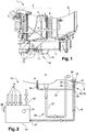
- an aircraft engine 1 (here of a helicopter) comprises (seen in transparency) a gas generator 2, formed of a compressor 3, a combustion chamber 4 and a turbine 5, in connection with a free turbine 6.
- the free turbine 6 drives the main rotor (not shown) by a power shaft 7 via a box transmission (not shown).
- the gases from the combustion are ejected into an exhaust nozzle 9.
- the engine 1 is equipped with a drainage device 10 which is intended to collect the residual fluids (fuel, oil, water condensates, impurities, etc.) coming from the engine.
- a drainage device 10 which is intended to collect the residual fluids (fuel, oil, water condensates, impurities, etc.) coming from the engine.
- a drainage device 10 comprises a manifold 11 and conduits 12 for draining fluids coming from different parts of the engine and having their outlets opening into the manifold 11.
- a fluid drainage device further comprises means for pumping the fluids contained in the collector 11 and for evacuating these fluids, as well as monitoring means configured to signal an abnormal collection of the fluids by the collector 11 .
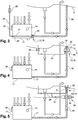
- the figure 2 represents a first embodiment of the drainage device 10 according to the invention, in which the pumping and evacuation means and the monitoring means are designated by the references 13 and 14 respectively.
- the pumping and evacuation means 13 comprise an inlet 15 connected by a pipe 16 to an outlet 17 for fluids from the manifold 11, and an outlet 18 opening into the exhaust nozzle 9 of the engine 1.
- the collector 11 receives the drained fluids coming from the conduits 12 (schematically represented by arrows) and is preferably equipped with a vent 12 ′ for venting the internal cavity of the collector, in which the fluids are received .
- the pumping and evacuation means 13 here comprise an ejector 19 of the jet pump type, provided with a first conduit 20 for passage of drained fluids, one end (upstream) of which forms the abovementioned inlet 15 and the other end of which (downstream) forms the aforementioned outlet 18.
- this outlet 18 may include a restriction of its passage section so as to define a diffuser downstream.
- the pumping and evacuation means 13 also comprise a second duct 21 for spraying pressurized gas which here extends inside the first duct 20 and which is configured so that the sprayed gas leaving this second duct 21 forces the evacuation of the fluids circulating in the conduit 20 towards its outlet 18 and in the nozzle 9.
- This pressurized gas is intended to expand in the aforementioned diffuser, which creates a vacuum and forces the passage of the drained fluids into the nozzle 9.
- the second conduit 21 thus comprises an outlet 22 for pressurized gas situated in the vicinity of the outlet 18 of the first conduit 20.
- the inlet 23 of the second conduit is connected by a conduit 24 to means for withdrawing pressurized gas from the engine 1 (not shown in the drawing).
- the sampling of pressurized gas can be carried out in the compressor 3 of the engine, for example at the plane P25 or P3 (the plane P25 being located between two compression wheels and the plane P3 being located downstream of these wheels).
- the pipe 24 is equipped with a flap valve 25 which is intended to open and let the pressurized gas taken from the pipe to the ejector 19 when the pressure of this gas is greater than or equal to a predetermined threshold value.
- the flap valve 25 is here represented by a movable ball urged by a compression spring against a seat surrounding a gas outlet of the sampling means. Thus, the flap valve 25 is actuated by the pressurized gas.
- the aforementioned threshold value of the gas pressure which is in particular a function of the stiffness of the spring in the aforementioned example, is preferably determined to precisely control the moment of evacuation of the drained fluids, in particular so that it does not occur not when the engine is started.
- the monitoring means 14 of the manifold 11 are here represented by a simple overflow 34. According to the invention, these monitoring means 14 are configured to activate when the flow of fluids received by the manifold 11 is greater than the flow of pumping means 13 (ejector 19). The monitoring means 14 thus make it possible to signal an abnormal collection of fluids by the collector 11, in particular an amount that is too high by compared to the usual amount of fluids drained during normal engine operation.
- the monitoring means 14 can be designed to emit a signal, which can be a visual and / or electrical alarm.
- the pumping means 13 are no longer able to evacuate the collected fluids as soon as the flow of collected fluids is greater than the pumping flow. If the collector allows it, the level of fluids in the collector 11 will therefore increase in the event of an engine failure.
- the monitoring means 14 include this window which is thus intended to alert the operator (visual alarm).
- the collector 11 may alternatively or as an additional characteristic comprise an overflow 34 intended to allow fluids from the collector 11 to escape, in particular when the volume of fluids collected is greater than the volume of retention of the fluids from the collector 11.
- An operator can see, in place of or in addition to the alarm means, the traces of flow generated by an overflow at the level of the overflow 34 in the event that an engine failure has occurred, the overflow 34 thus forming another type visual alarm.
- the overflow 34 can be connected by a hose to the scupper of the engine compartment floor, or to an auxiliary recovery tank.
- the monitoring means 14 may comprise a sensor intended to detect the level of fluids in the manifold 11 and to emit a signal intended for the cockpit of the aircraft which may be visible by the pilot through an indicator light for example.
- the monitoring means 14 thus make it possible to detect a large and abnormal leakage of fluids quickly enough to alert an operator or the pilot of the aircraft.
- the activation of the alarm indicates that an engine failure has occurred and that a maintenance operation must be carried out.
- the engine partially shown in figure 2 comprises other drainage means 26 which are used here to collect unburned fuel in the combustion chamber 4 and to evacuate it to the nozzle 9 by means of a pipe 27, the outlet of which opens into the nozzle.
- the drainage device 10 according to the invention is independent of these drainage means 26 which are not equipped with pumping means or with monitoring means.
- the pumping means 13 (ejector 19) are integrated into the manifold 11.
- the first conduit 20 is directly mounted at the outlet 17 for fluids from the manifold 11 and is connected to one end of a conduit 16, the other end of which opens into the nozzle 9.
- the second conduit 21 of the ejector 19 extends inside the first conduit 20 and its inlet 23 is connected by a conduit 24 which can be fitted with a flap valve 25 to the gas sampling means under pressure in the engine 1.
- the drainage device of the figure 3 also includes monitoring means 14 of the aforementioned type.
- the pumping means 13 comprise an ejector 19, the first conduit 20 of which is mounted inside the second conduit 21, so as to form a nozzle.
- the inlet of the first conduit 20 is connected by the conduit 16 to the outlet 17 of fluids from the manifold 11.
- the second conduit 21 has its inlet connected by a conduit 24 to the air intake means and its outlet extends around the outlet of the first conduit 20 and opens into the nozzle 9.
- the ejector 19 functions here as a paint spray gun type ejection nozzle, which operates by expelling the pressurized gas around the outlet 18 of the first conduit 20, in order to suck the fluids from the manifold towards the nozzle 9 11.
- the pipe 24 connecting the second pipe 21 of the ejector to the withdrawal means is equipped with a restriction 28 of its passage section (instead of the flap valve 25 of the figure 2 ).
- This restriction 28 makes it possible to delay the evacuation of the fluids so that it does not intervene when the engine is started.
- the pressure increases slightly in the second conduit 21 of the ejector at start-up, the evacuation of the fluids in the nozzle 9 occurring beyond a predetermined pressure threshold.
- the drainage device also includes monitoring means 14 of the aforementioned type.
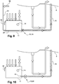
- the variant of the figure 5 differs from the embodiment of the figure 2 essentially in that line 24 is not equipped with a flap valve or restriction. Instead, a valve 29, for example with a slide valve, is mounted on the pipe 16 which connects the outlet 17 of the manifold 11 to the inlet of the first pipe 20 of the ejector 19.
- the valve 29 comprises an inlet connected by a portion of line 16 to the outlet 17 of the manifold 11 and an outlet connected by another portion of line 16 to the inlet of the first duct 20 of the ejector 19.
- the valve 29 comprises in addition to an internal member 30 movable between a position for closing the above-mentioned outlet and / or inlet of the valve 29, and a position in which the inlet and the outlet of the valve 29 are in fluid communication.
- the member 30 is biased by a spring in the closed position of the valve 29. The movement of this member 30 is controlled by pressurized gas, which here is a part of the pressurized gas taken from the engine by the means of aforementioned direct debit.
- the pipe 24 connecting the sampling means to the ejector 19 may include a bypass 31 connected to a cavity of the valve 29, in which the member is mounted to move.
- the valve 29 is intended to open when the pressure of the withdrawn gas is greater than or equal to a predetermined threshold value, which is in particular a function of the stiffness of the spring in the above example, and which is preferably determined to precisely control the moment of evacuation of the drained fluids, in particular so that it does not occur upon ignition of the engine.
- the pipe 31 can be connected by its end opposite the valve to means for taking air from the engine compressor.
- the variant of the figure 6 differs from the embodiment of the figure 2 essentially in that the line 24 is connected to means for sampling gas under pressure, not in the engine compressor, but in a degassing system (not shown) of the engine.
- the evacuation of the fluids in the nozzle 9 occurs using the engine degassing system.
- the variant of the figure 7 differs from the embodiment of the figure 3 essentially in that the pipe 24 connecting the second pipe 21 of the ejector to the withdrawal means, is equipped with a restriction 28 of its passage section (instead of the flap valve 25 of the figure 3 ).
- This restriction 28 has the same function as the restriction described with reference to the figure 4 .
- the variant of the figure 8 differs from the embodiment of the figure 2 essentially in that the pipe 24 connecting the second pipe 21 of the ejector to the withdrawal means, is equipped with a restriction 28 of its passage section (instead of the flap valve 25 of the figure 2 ).
- This restriction 28 has the same function as the restriction described with reference to the figure 4 .
- the variant of the figure 9 differs from the embodiment of the figure 3 essentially in that the line 24 connecting the second line 21 of the ejector 19 to the withdrawal means, is equipped with a valve 32 electrically controlled (instead of the flap valve 25 of the figure 3 ).
- This valve 32 is intended to open to let the pressurized gas withdrawn when it is activated by an order sent by an engine computer for example.
- the pumping means 13 of the drainage device comprise an electric pump 33 or mechanical mounted on the pipe 16 and one end of which is connected to the outlet 17 of the manifold 11 and the opposite end opens into the nozzle 9.
- This pump 33 brings the fluids from the manifold 11 to the nozzle 9, when it is actuated .
- the flow of this pump is also calibrated so as to fix a flow threshold beyond which the monitoring device signals abnormal engine operation. This variant does not require a valve, restriction or air intake.
- the drainage device also includes monitoring means 14 of the aforementioned type.
Landscapes
- Engineering & Computer Science (AREA)
- Chemical & Material Sciences (AREA)
- Combustion & Propulsion (AREA)
- Mechanical Engineering (AREA)
- General Engineering & Computer Science (AREA)
- Aviation & Aerospace Engineering (AREA)
- Lubrication Details And Ventilation Of Internal Combustion Engines (AREA)
- Exhaust Gas After Treatment (AREA)
- Loading And Unloading Of Fuel Tanks Or Ships (AREA)
- Testing Of Engines (AREA)
- Sampling And Sample Adjustment (AREA)
- Jet Pumps And Other Pumps (AREA)
Priority Applications (1)
| Application Number | Priority Date | Filing Date | Title |
|---|---|---|---|
| PL14827837T PL3084187T3 (pl) | 2013-12-19 | 2014-12-15 | Urządzenie do odprowadzania płynów przeznaczone dla silnika statku powietrznego |
Applications Claiming Priority (2)
| Application Number | Priority Date | Filing Date | Title |
|---|---|---|---|
| FR1363087A FR3015567B1 (fr) | 2013-12-19 | 2013-12-19 | Dispositif de drainage de fluides pour un moteur d'aeronef |
| PCT/FR2014/053333 WO2015092243A1 (fr) | 2013-12-19 | 2014-12-15 | Dispositif de drainage de fluides pour un moteur d'aéronef |
Publications (2)
| Publication Number | Publication Date |
|---|---|
| EP3084187A1 EP3084187A1 (fr) | 2016-10-26 |
| EP3084187B1 true EP3084187B1 (fr) | 2020-02-26 |
Family
ID=50289992
Family Applications (1)
| Application Number | Title | Priority Date | Filing Date |
|---|---|---|---|
| EP14827837.7A Active EP3084187B1 (fr) | 2013-12-19 | 2014-12-15 | Dispositif de drainage de fluides pour un moteur d'aéronef |
Country Status (10)
| Country | Link |
|---|---|
| US (1) | US10539077B2 (ru) |
| EP (1) | EP3084187B1 (ru) |
| JP (1) | JP2017503951A (ru) |
| KR (1) | KR20160094990A (ru) |
| CN (1) | CN105829681B (ru) |
| CA (1) | CA2933531C (ru) |
| FR (1) | FR3015567B1 (ru) |
| PL (1) | PL3084187T3 (ru) |
| RU (1) | RU2666719C1 (ru) |
| WO (1) | WO2015092243A1 (ru) |
Families Citing this family (10)
| Publication number | Priority date | Publication date | Assignee | Title |
|---|---|---|---|---|
| US11512811B2 (en) | 2016-07-12 | 2022-11-29 | Sikorsky Aircraft Corporation | System and method for detecting a lubricant-out condition in an aircraft gearbox |
| NO343014B1 (en) * | 2017-03-24 | 2018-10-01 | Karmoey Winch As | A pumping system and method |
| FR3082507B1 (fr) * | 2018-06-14 | 2022-01-28 | Safran Aircraft Engines | Dispositif et procede de vidange et surveillance de fluide draine d'un moteur d'aeronef |
| FR3082560B1 (fr) * | 2018-06-14 | 2020-08-28 | Safran Aircraft Engines | Systeme embarque et procede pour le drainage d'un moteur d'aeronef |
| FR3082508B1 (fr) | 2018-06-14 | 2021-12-03 | Safran Aircraft Engines | Reservoir embarque de drainage d'un moteur d'aeronef |
| CN109319159B (zh) * | 2018-11-28 | 2024-03-15 | 江西荣力航空工业有限公司 | 一种直升机发动机余油收集、排放装置 |
| CN111980803B (zh) * | 2019-05-24 | 2022-03-15 | 中国航发商用航空发动机有限责任公司 | 一种航空发动机 |
| EP3798113B1 (en) * | 2019-09-30 | 2023-03-29 | Rohr, Inc. | Fluid drainage system for an aircraft propulsion system |
| FR3114128B1 (fr) | 2020-09-14 | 2022-11-04 | Airbus Helicopters | Système de drainage d’un moteur à combustion d’aéronef et aéronef associé |
| FR3137408A1 (fr) | 2022-06-29 | 2024-01-05 | Safran Helicopter Engines | Ensemble drainé d’une turbomachine d’aéronef |
Family Cites Families (18)
| Publication number | Priority date | Publication date | Assignee | Title |
|---|---|---|---|---|
| FR1597209A (ru) * | 1968-02-02 | 1970-06-22 | ||
| US3623053A (en) * | 1969-10-23 | 1971-11-23 | Gen Electric | Leak-detecting apparatus |
| GB1402996A (en) * | 1971-10-28 | 1975-08-13 | Plessey Co Ltd | Fuel-supply systems for gas-turbine engines |
| JPS61123787A (ja) * | 1984-11-16 | 1986-06-11 | Mitsubishi Heavy Ind Ltd | 油圧機器の異常監視装置 |
| US5285636A (en) * | 1992-10-28 | 1994-02-15 | General Electric Company | Diagnostic drain mast for a gas turbine engine |
| JP3307734B2 (ja) * | 1993-09-29 | 2002-07-24 | 株式会社日立国際電気 | 警報機能付きフライトデータレコーダ |
| FR2726603B1 (fr) * | 1994-11-09 | 1996-12-13 | Snecma | Dispositif de controle actif des instabilites de combustion et de decokefaction d'un injecteur de carburant |
| IT1318110B1 (it) * | 2000-07-03 | 2003-07-23 | Nuovo Pignone Spa | Sistema di scarico e di refrigerazione per i cuscini di una turbina agas |
| US6578361B1 (en) * | 2001-08-30 | 2003-06-17 | General Electric Co. | Methods and apparatus for determining engine cavity leakage |
| US6571562B2 (en) * | 2001-10-08 | 2003-06-03 | Honeywell International Inc. | Witness drain valve |
| JP4504231B2 (ja) * | 2005-03-02 | 2010-07-14 | 株式会社東芝 | 発電プラントの再熱システム |
| FR2913250B1 (fr) * | 2007-03-02 | 2009-05-29 | Turbomeca Sa | Procede pour le demarrage d'un moteur d'helicoptere a turbine a gaz, circuit d'alimentation en carburant d'un tel moteur, et moteur ayant un tel circuit. |
| EP2052792A3 (en) * | 2007-10-09 | 2011-06-22 | Gas Turbine Efficiency Sweden AB | Drain valve, washing system and sensing of rinse and wash completion |
| EP2536536A1 (en) * | 2010-02-17 | 2012-12-26 | GARDENA Manufacturing GmbH | Power tools |
| US20130327059A1 (en) * | 2011-03-01 | 2013-12-12 | Short Brothers Plc | Draining device |
| US8708554B2 (en) * | 2011-05-12 | 2014-04-29 | Arrowhead Products Corporation | Leak detection apparatus for aircraft bleed air systems |
| FR2986583B1 (fr) * | 2012-02-08 | 2014-02-28 | Eurocopter France | Circuit de drainage d'un liquide en provenance d'un groupe de motorisation equipant un giravion, integrant un appareil de surveillance d'un ecoulement excessif du liquide |
| EP3013682B1 (en) * | 2013-06-27 | 2018-05-16 | MAG Aerospace Industries, LLC | Water management system |
-
2013
- 2013-12-19 FR FR1363087A patent/FR3015567B1/fr active Active
-
2014
- 2014-12-15 CN CN201480068556.2A patent/CN105829681B/zh active Active
- 2014-12-15 KR KR1020167016369A patent/KR20160094990A/ko not_active Application Discontinuation
- 2014-12-15 WO PCT/FR2014/053333 patent/WO2015092243A1/fr active Application Filing
- 2014-12-15 PL PL14827837T patent/PL3084187T3/pl unknown
- 2014-12-15 RU RU2016125764A patent/RU2666719C1/ru active
- 2014-12-15 EP EP14827837.7A patent/EP3084187B1/fr active Active
- 2014-12-15 CA CA2933531A patent/CA2933531C/fr active Active
- 2014-12-15 JP JP2016539936A patent/JP2017503951A/ja active Pending
- 2014-12-15 US US15/104,462 patent/US10539077B2/en active Active
Non-Patent Citations (1)
| Title |
|---|
| None * |
Also Published As
| Publication number | Publication date |
|---|---|
| RU2666719C1 (ru) | 2018-09-11 |
| US10539077B2 (en) | 2020-01-21 |
| CN105829681B (zh) | 2018-07-10 |
| CN105829681A (zh) | 2016-08-03 |
| FR3015567A1 (fr) | 2015-06-26 |
| WO2015092243A1 (fr) | 2015-06-25 |
| CA2933531A1 (fr) | 2015-06-25 |
| JP2017503951A (ja) | 2017-02-02 |
| PL3084187T3 (pl) | 2020-06-29 |
| KR20160094990A (ko) | 2016-08-10 |
| EP3084187A1 (fr) | 2016-10-26 |
| CA2933531C (fr) | 2022-03-22 |
| RU2016125764A (ru) | 2018-01-24 |
| US20160312707A1 (en) | 2016-10-27 |
| FR3015567B1 (fr) | 2015-12-25 |
Similar Documents
| Publication | Publication Date | Title |
|---|---|---|
| EP3084187B1 (fr) | Dispositif de drainage de fluides pour un moteur d'aéronef | |
| EP3181951B1 (fr) | Dispositif de lubrification de secours d' architecture simplifiee pour une boite de transmission principale de puissance d'un aeronef | |
| CA2931231C (fr) | Mat d'evacuation de fluides draines pour un ensemble propulsif | |
| EP2619419B1 (fr) | Systeme de pressurisation des enceintes de paliers des turbomachines par de l'air preleve dans la manche d'entree | |
| EP3087265B1 (fr) | Ensemble propulsif d'aeronef avec systeme d'extinction de feu et procede de ventilation | |
| FR2902755A1 (fr) | Systeme de projection de liquide de projection pour pare-brise d'aeronef, et cockpit muni d'un tel systeme de projection | |
| FR2996597A1 (fr) | Systeme de ventilation de la chambre de palier d'un moteur d'avion et son procede de mise en oeuvre | |
| FR2902754A1 (fr) | Systeme de projection de liquide de projection pour pare-brise d'aeronef, et cockpit muni d'un tel systeme de projection | |
| EP3601765B1 (fr) | Dispositif amélioré d'augmentation temporaire de puissance de turbomachine | |
| CA2818705C (fr) | Dispositif d'evacuation d'huile et turbomachine comprenant un tel dispositif | |
| FR3007391A1 (fr) | Installation motrice multimoteur munie d'un systeme de secours d'injection de fluide et aeronef | |
| FR2979387A1 (fr) | Circuit de carburant dans une turbomachine | |
| EP2697493B1 (fr) | Circuit de carburant comportant des moyens de controle d'une pompe | |
| FR3083266A1 (fr) | Ensemble pour turbomachine d'aeronef comportant un systeme ameliore de lubrification d'un reducteur d'entrainement de soufflante en cas d'autorotation de la soufflante | |
| EP3933182B1 (fr) | Systeme et procede de filtration d'air à media filtrant autonettoyant pour un moteur d'un aeronef | |
| WO2017060653A1 (fr) | Dispositif d'actionnement pour systeme d'eolienne de secours d'aeronef | |
| FR3013075A1 (fr) | Systeme d'alimentation en huile par pompe a jet | |
| FR3050760A1 (fr) | Systeme de vanne de decharge pour une turbomachine d'aeronef |
Legal Events
| Date | Code | Title | Description |
|---|---|---|---|
| PUAI | Public reference made under article 153(3) epc to a published international application that has entered the european phase |
Free format text: ORIGINAL CODE: 0009012 |
|
| 17P | Request for examination filed |
Effective date: 20160617 |
|
| AK | Designated contracting states |
Kind code of ref document: A1 Designated state(s): AL AT BE BG CH CY CZ DE DK EE ES FI FR GB GR HR HU IE IS IT LI LT LU LV MC MK MT NL NO PL PT RO RS SE SI SK SM TR |
|
| AX | Request for extension of the european patent |
Extension state: BA ME |
|
| RIN1 | Information on inventor provided before grant (corrected) |
Inventor name: PY, JEAN-MICHEL, PIERRE, CLAUDE Inventor name: BENEZECH, PHILIPPE, JEAN, RENE, MARIE Inventor name: COMBEBIAS, SEBASTIEN Inventor name: LE BORGNE, ERIC Inventor name: HERNANDEZ, LORENZO, HUACAN Inventor name: FOUCHE, SEBASTIEN Inventor name: NAPIAS, LIONEL Inventor name: ZORDAN, CEDRIC Inventor name: ROGER, PHILIPPE Inventor name: QUAIREAU, MAXIME |
|
| RAP1 | Party data changed (applicant data changed or rights of an application transferred) |
Owner name: SAFRAN HELICOPTER ENGINES |
|
| DAX | Request for extension of the european patent (deleted) | ||
| STAA | Information on the status of an ep patent application or granted ep patent |
Free format text: STATUS: EXAMINATION IS IN PROGRESS |
|
| 17Q | First examination report despatched |
Effective date: 20190621 |
|
| GRAP | Despatch of communication of intention to grant a patent |
Free format text: ORIGINAL CODE: EPIDOSNIGR1 |
|
| STAA | Information on the status of an ep patent application or granted ep patent |
Free format text: STATUS: GRANT OF PATENT IS INTENDED |
|
| INTG | Intention to grant announced |
Effective date: 20191009 |
|
| GRAS | Grant fee paid |
Free format text: ORIGINAL CODE: EPIDOSNIGR3 |
|
| GRAA | (expected) grant |
Free format text: ORIGINAL CODE: 0009210 |
|
| STAA | Information on the status of an ep patent application or granted ep patent |
Free format text: STATUS: THE PATENT HAS BEEN GRANTED |
|
| AK | Designated contracting states |
Kind code of ref document: B1 Designated state(s): AL AT BE BG CH CY CZ DE DK EE ES FI FR GB GR HR HU IE IS IT LI LT LU LV MC MK MT NL NO PL PT RO RS SE SI SK SM TR |
|
| REG | Reference to a national code |
Ref country code: GB Ref legal event code: FG4D Free format text: NOT ENGLISH |
|
| REG | Reference to a national code |
Ref country code: CH Ref legal event code: EP |
|
| REG | Reference to a national code |
Ref country code: AT Ref legal event code: REF Ref document number: 1237903 Country of ref document: AT Kind code of ref document: T Effective date: 20200315 |
|
| REG | Reference to a national code |
Ref country code: IE Ref legal event code: FG4D Free format text: LANGUAGE OF EP DOCUMENT: FRENCH |
|
| REG | Reference to a national code |
Ref country code: DE Ref legal event code: R096 Ref document number: 602014061618 Country of ref document: DE |
|
| PG25 | Lapsed in a contracting state [announced via postgrant information from national office to epo] |
Ref country code: FI Free format text: LAPSE BECAUSE OF FAILURE TO SUBMIT A TRANSLATION OF THE DESCRIPTION OR TO PAY THE FEE WITHIN THE PRESCRIBED TIME-LIMIT Effective date: 20200226 Ref country code: RS Free format text: LAPSE BECAUSE OF FAILURE TO SUBMIT A TRANSLATION OF THE DESCRIPTION OR TO PAY THE FEE WITHIN THE PRESCRIBED TIME-LIMIT Effective date: 20200226 Ref country code: NO Free format text: LAPSE BECAUSE OF FAILURE TO SUBMIT A TRANSLATION OF THE DESCRIPTION OR TO PAY THE FEE WITHIN THE PRESCRIBED TIME-LIMIT Effective date: 20200526 |
|
| REG | Reference to a national code |
Ref country code: NL Ref legal event code: MP Effective date: 20200226 |
|
| REG | Reference to a national code |
Ref country code: LT Ref legal event code: MG4D |
|
| PG25 | Lapsed in a contracting state [announced via postgrant information from national office to epo] |
Ref country code: IS Free format text: LAPSE BECAUSE OF FAILURE TO SUBMIT A TRANSLATION OF THE DESCRIPTION OR TO PAY THE FEE WITHIN THE PRESCRIBED TIME-LIMIT Effective date: 20200626 Ref country code: BG Free format text: LAPSE BECAUSE OF FAILURE TO SUBMIT A TRANSLATION OF THE DESCRIPTION OR TO PAY THE FEE WITHIN THE PRESCRIBED TIME-LIMIT Effective date: 20200526 Ref country code: GR Free format text: LAPSE BECAUSE OF FAILURE TO SUBMIT A TRANSLATION OF THE DESCRIPTION OR TO PAY THE FEE WITHIN THE PRESCRIBED TIME-LIMIT Effective date: 20200527 Ref country code: LV Free format text: LAPSE BECAUSE OF FAILURE TO SUBMIT A TRANSLATION OF THE DESCRIPTION OR TO PAY THE FEE WITHIN THE PRESCRIBED TIME-LIMIT Effective date: 20200226 Ref country code: SE Free format text: LAPSE BECAUSE OF FAILURE TO SUBMIT A TRANSLATION OF THE DESCRIPTION OR TO PAY THE FEE WITHIN THE PRESCRIBED TIME-LIMIT Effective date: 20200226 Ref country code: HR Free format text: LAPSE BECAUSE OF FAILURE TO SUBMIT A TRANSLATION OF THE DESCRIPTION OR TO PAY THE FEE WITHIN THE PRESCRIBED TIME-LIMIT Effective date: 20200226 |
|
| PG25 | Lapsed in a contracting state [announced via postgrant information from national office to epo] |
Ref country code: NL Free format text: LAPSE BECAUSE OF FAILURE TO SUBMIT A TRANSLATION OF THE DESCRIPTION OR TO PAY THE FEE WITHIN THE PRESCRIBED TIME-LIMIT Effective date: 20200226 |
|
| PG25 | Lapsed in a contracting state [announced via postgrant information from national office to epo] |
Ref country code: EE Free format text: LAPSE BECAUSE OF FAILURE TO SUBMIT A TRANSLATION OF THE DESCRIPTION OR TO PAY THE FEE WITHIN THE PRESCRIBED TIME-LIMIT Effective date: 20200226 Ref country code: SM Free format text: LAPSE BECAUSE OF FAILURE TO SUBMIT A TRANSLATION OF THE DESCRIPTION OR TO PAY THE FEE WITHIN THE PRESCRIBED TIME-LIMIT Effective date: 20200226 Ref country code: ES Free format text: LAPSE BECAUSE OF FAILURE TO SUBMIT A TRANSLATION OF THE DESCRIPTION OR TO PAY THE FEE WITHIN THE PRESCRIBED TIME-LIMIT Effective date: 20200226 Ref country code: LT Free format text: LAPSE BECAUSE OF FAILURE TO SUBMIT A TRANSLATION OF THE DESCRIPTION OR TO PAY THE FEE WITHIN THE PRESCRIBED TIME-LIMIT Effective date: 20200226 Ref country code: PT Free format text: LAPSE BECAUSE OF FAILURE TO SUBMIT A TRANSLATION OF THE DESCRIPTION OR TO PAY THE FEE WITHIN THE PRESCRIBED TIME-LIMIT Effective date: 20200719 Ref country code: DK Free format text: LAPSE BECAUSE OF FAILURE TO SUBMIT A TRANSLATION OF THE DESCRIPTION OR TO PAY THE FEE WITHIN THE PRESCRIBED TIME-LIMIT Effective date: 20200226 Ref country code: SK Free format text: LAPSE BECAUSE OF FAILURE TO SUBMIT A TRANSLATION OF THE DESCRIPTION OR TO PAY THE FEE WITHIN THE PRESCRIBED TIME-LIMIT Effective date: 20200226 Ref country code: RO Free format text: LAPSE BECAUSE OF FAILURE TO SUBMIT A TRANSLATION OF THE DESCRIPTION OR TO PAY THE FEE WITHIN THE PRESCRIBED TIME-LIMIT Effective date: 20200226 |
|
| REG | Reference to a national code |
Ref country code: AT Ref legal event code: MK05 Ref document number: 1237903 Country of ref document: AT Kind code of ref document: T Effective date: 20200226 |
|
| REG | Reference to a national code |
Ref country code: DE Ref legal event code: R097 Ref document number: 602014061618 Country of ref document: DE |
|
| PLBE | No opposition filed within time limit |
Free format text: ORIGINAL CODE: 0009261 |
|
| STAA | Information on the status of an ep patent application or granted ep patent |
Free format text: STATUS: NO OPPOSITION FILED WITHIN TIME LIMIT |
|
| PG25 | Lapsed in a contracting state [announced via postgrant information from national office to epo] |
Ref country code: AT Free format text: LAPSE BECAUSE OF FAILURE TO SUBMIT A TRANSLATION OF THE DESCRIPTION OR TO PAY THE FEE WITHIN THE PRESCRIBED TIME-LIMIT Effective date: 20200226 |
|
| 26N | No opposition filed |
Effective date: 20201127 |
|
| PG25 | Lapsed in a contracting state [announced via postgrant information from national office to epo] |
Ref country code: SI Free format text: LAPSE BECAUSE OF FAILURE TO SUBMIT A TRANSLATION OF THE DESCRIPTION OR TO PAY THE FEE WITHIN THE PRESCRIBED TIME-LIMIT Effective date: 20200226 |
|
| REG | Reference to a national code |
Ref country code: CH Ref legal event code: PL |
|
| PG25 | Lapsed in a contracting state [announced via postgrant information from national office to epo] |
Ref country code: MC Free format text: LAPSE BECAUSE OF FAILURE TO SUBMIT A TRANSLATION OF THE DESCRIPTION OR TO PAY THE FEE WITHIN THE PRESCRIBED TIME-LIMIT Effective date: 20200226 |
|
| REG | Reference to a national code |
Ref country code: BE Ref legal event code: MM Effective date: 20201231 |
|
| PG25 | Lapsed in a contracting state [announced via postgrant information from national office to epo] |
Ref country code: IE Free format text: LAPSE BECAUSE OF NON-PAYMENT OF DUE FEES Effective date: 20201215 Ref country code: LU Free format text: LAPSE BECAUSE OF NON-PAYMENT OF DUE FEES Effective date: 20201215 |
|
| PG25 | Lapsed in a contracting state [announced via postgrant information from national office to epo] |
Ref country code: CH Free format text: LAPSE BECAUSE OF NON-PAYMENT OF DUE FEES Effective date: 20201231 Ref country code: LI Free format text: LAPSE BECAUSE OF NON-PAYMENT OF DUE FEES Effective date: 20201231 |
|
| PG25 | Lapsed in a contracting state [announced via postgrant information from national office to epo] |
Ref country code: TR Free format text: LAPSE BECAUSE OF FAILURE TO SUBMIT A TRANSLATION OF THE DESCRIPTION OR TO PAY THE FEE WITHIN THE PRESCRIBED TIME-LIMIT Effective date: 20200226 Ref country code: MT Free format text: LAPSE BECAUSE OF FAILURE TO SUBMIT A TRANSLATION OF THE DESCRIPTION OR TO PAY THE FEE WITHIN THE PRESCRIBED TIME-LIMIT Effective date: 20200226 Ref country code: CY Free format text: LAPSE BECAUSE OF FAILURE TO SUBMIT A TRANSLATION OF THE DESCRIPTION OR TO PAY THE FEE WITHIN THE PRESCRIBED TIME-LIMIT Effective date: 20200226 |
|
| PG25 | Lapsed in a contracting state [announced via postgrant information from national office to epo] |
Ref country code: MK Free format text: LAPSE BECAUSE OF FAILURE TO SUBMIT A TRANSLATION OF THE DESCRIPTION OR TO PAY THE FEE WITHIN THE PRESCRIBED TIME-LIMIT Effective date: 20200226 Ref country code: AL Free format text: LAPSE BECAUSE OF FAILURE TO SUBMIT A TRANSLATION OF THE DESCRIPTION OR TO PAY THE FEE WITHIN THE PRESCRIBED TIME-LIMIT Effective date: 20200226 |
|
| PG25 | Lapsed in a contracting state [announced via postgrant information from national office to epo] |
Ref country code: BE Free format text: LAPSE BECAUSE OF NON-PAYMENT OF DUE FEES Effective date: 20201231 |
|
| PGFP | Annual fee paid to national office [announced via postgrant information from national office to epo] |
Ref country code: IT Payment date: 20221122 Year of fee payment: 9 Ref country code: CZ Payment date: 20221128 Year of fee payment: 9 |
|
| PGFP | Annual fee paid to national office [announced via postgrant information from national office to epo] |
Ref country code: PL Payment date: 20221124 Year of fee payment: 9 |
|
| PGFP | Annual fee paid to national office [announced via postgrant information from national office to epo] |
Ref country code: GB Payment date: 20231121 Year of fee payment: 10 |
|
| PGFP | Annual fee paid to national office [announced via postgrant information from national office to epo] |
Ref country code: FR Payment date: 20231122 Year of fee payment: 10 Ref country code: DE Payment date: 20231121 Year of fee payment: 10 |