EP3084184B1 - Kühlkanal für schaufelaussendichtung - Google Patents
Kühlkanal für schaufelaussendichtung Download PDFInfo
- Publication number
- EP3084184B1 EP3084184B1 EP14883695.0A EP14883695A EP3084184B1 EP 3084184 B1 EP3084184 B1 EP 3084184B1 EP 14883695 A EP14883695 A EP 14883695A EP 3084184 B1 EP3084184 B1 EP 3084184B1
- Authority
- EP
- European Patent Office
- Prior art keywords
- region
- wall
- cooling
- gas turbine
- cooling passage
- Prior art date
- Legal status (The legal status is an assumption and is not a legal conclusion. Google has not performed a legal analysis and makes no representation as to the accuracy of the status listed.)
- Active
Links
- 238000001816 cooling Methods 0.000 title claims description 40
- 239000012530 fluid Substances 0.000 claims description 7
- 238000004891 communication Methods 0.000 claims description 5
- 238000007789 sealing Methods 0.000 claims description 3
- 230000000712 assembly Effects 0.000 description 3
- 238000000429 assembly Methods 0.000 description 3
- 239000012809 cooling fluid Substances 0.000 description 3
- 238000013461 design Methods 0.000 description 2
- 230000003068 static effect Effects 0.000 description 2
- 238000011161 development Methods 0.000 description 1
- 238000005553 drilling Methods 0.000 description 1
- 238000003754 machining Methods 0.000 description 1
- 238000012986 modification Methods 0.000 description 1
- 230000004048 modification Effects 0.000 description 1
- 238000010926 purge Methods 0.000 description 1
- 238000011160 research Methods 0.000 description 1
- 238000011144 upstream manufacturing Methods 0.000 description 1
Images


Classifications
-
- F—MECHANICAL ENGINEERING; LIGHTING; HEATING; WEAPONS; BLASTING
- F01—MACHINES OR ENGINES IN GENERAL; ENGINE PLANTS IN GENERAL; STEAM ENGINES
- F01D—NON-POSITIVE DISPLACEMENT MACHINES OR ENGINES, e.g. STEAM TURBINES
- F01D25/00—Component parts, details, or accessories, not provided for in, or of interest apart from, other groups
- F01D25/08—Cooling; Heating; Heat-insulation
- F01D25/12—Cooling
-
- F—MECHANICAL ENGINEERING; LIGHTING; HEATING; WEAPONS; BLASTING
- F01—MACHINES OR ENGINES IN GENERAL; ENGINE PLANTS IN GENERAL; STEAM ENGINES
- F01D—NON-POSITIVE DISPLACEMENT MACHINES OR ENGINES, e.g. STEAM TURBINES
- F01D11/00—Preventing or minimising internal leakage of working-fluid, e.g. between stages
- F01D11/08—Preventing or minimising internal leakage of working-fluid, e.g. between stages for sealing space between rotor blade tips and stator
- F01D11/14—Adjusting or regulating tip-clearance, i.e. distance between rotor-blade tips and stator casing
- F01D11/20—Actively adjusting tip-clearance
- F01D11/24—Actively adjusting tip-clearance by selectively cooling-heating stator or rotor components
-
- F—MECHANICAL ENGINEERING; LIGHTING; HEATING; WEAPONS; BLASTING
- F05—INDEXING SCHEMES RELATING TO ENGINES OR PUMPS IN VARIOUS SUBCLASSES OF CLASSES F01-F04
- F05D—INDEXING SCHEME FOR ASPECTS RELATING TO NON-POSITIVE-DISPLACEMENT MACHINES OR ENGINES, GAS-TURBINES OR JET-PROPULSION PLANTS
- F05D2220/00—Application
- F05D2220/30—Application in turbines
- F05D2220/32—Application in turbines in gas turbines
-
- F—MECHANICAL ENGINEERING; LIGHTING; HEATING; WEAPONS; BLASTING
- F05—INDEXING SCHEMES RELATING TO ENGINES OR PUMPS IN VARIOUS SUBCLASSES OF CLASSES F01-F04
- F05D—INDEXING SCHEME FOR ASPECTS RELATING TO NON-POSITIVE-DISPLACEMENT MACHINES OR ENGINES, GAS-TURBINES OR JET-PROPULSION PLANTS
- F05D2240/00—Components
- F05D2240/10—Stators
- F05D2240/11—Shroud seal segments
-
- F—MECHANICAL ENGINEERING; LIGHTING; HEATING; WEAPONS; BLASTING
- F05—INDEXING SCHEMES RELATING TO ENGINES OR PUMPS IN VARIOUS SUBCLASSES OF CLASSES F01-F04
- F05D—INDEXING SCHEME FOR ASPECTS RELATING TO NON-POSITIVE-DISPLACEMENT MACHINES OR ENGINES, GAS-TURBINES OR JET-PROPULSION PLANTS
- F05D2240/00—Components
- F05D2240/10—Stators
- F05D2240/12—Fluid guiding means, e.g. vanes
- F05D2240/127—Vortex generators, turbulators, or the like, for mixing
-
- F—MECHANICAL ENGINEERING; LIGHTING; HEATING; WEAPONS; BLASTING
- F05—INDEXING SCHEMES RELATING TO ENGINES OR PUMPS IN VARIOUS SUBCLASSES OF CLASSES F01-F04
- F05D—INDEXING SCHEME FOR ASPECTS RELATING TO NON-POSITIVE-DISPLACEMENT MACHINES OR ENGINES, GAS-TURBINES OR JET-PROPULSION PLANTS
- F05D2260/00—Function
- F05D2260/20—Heat transfer, e.g. cooling
- F05D2260/201—Heat transfer, e.g. cooling by impingement of a fluid
-
- F—MECHANICAL ENGINEERING; LIGHTING; HEATING; WEAPONS; BLASTING
- F05—INDEXING SCHEMES RELATING TO ENGINES OR PUMPS IN VARIOUS SUBCLASSES OF CLASSES F01-F04
- F05D—INDEXING SCHEME FOR ASPECTS RELATING TO NON-POSITIVE-DISPLACEMENT MACHINES OR ENGINES, GAS-TURBINES OR JET-PROPULSION PLANTS
- F05D2260/00—Function
- F05D2260/20—Heat transfer, e.g. cooling
- F05D2260/221—Improvement of heat transfer
- F05D2260/2212—Improvement of heat transfer by creating turbulence
-
- F—MECHANICAL ENGINEERING; LIGHTING; HEATING; WEAPONS; BLASTING
- F05—INDEXING SCHEMES RELATING TO ENGINES OR PUMPS IN VARIOUS SUBCLASSES OF CLASSES F01-F04
- F05D—INDEXING SCHEME FOR ASPECTS RELATING TO NON-POSITIVE-DISPLACEMENT MACHINES OR ENGINES, GAS-TURBINES OR JET-PROPULSION PLANTS
- F05D2260/00—Function
- F05D2260/20—Heat transfer, e.g. cooling
- F05D2260/221—Improvement of heat transfer
- F05D2260/2214—Improvement of heat transfer by increasing the heat transfer surface
- F05D2260/22141—Improvement of heat transfer by increasing the heat transfer surface using fins or ribs
Definitions
- This disclosure relates to a blade outer air seal (BOAS) and, more particularly, to a cooling passage for a BOAS.
- BOAS blade outer air seal
- Gas turbine engines generally include fan, compressor, combustor and turbine sections along an engine axis of rotation.
- the fan, compressor, and turbine sections each include a series of stator and rotor blade assemblies.
- a rotor and an axially adjacent array of stator assemblies may be referred to as a stage.
- Each stator vane assembly increases efficiency through the direction of core gas flow into or out of the rotor assemblies.
- An outer case supports multiple BOAS, which provide an outer radial flow path boundary.
- the BOAS are designed to accommodate thermal and dynamic variation typical in a high pressure turbine (HPT) section of the gas turbine engine.
- the BOAS are subjected to relatively high temperatures and receive a secondary cooling airflow for temperature control.
- the secondary cooling airflow is communicated into the BOAS through cooling channels within the BOAS for temperature control.
- BOAS One type of BOAS includes multiple discrete cooling passages, each of which are fed cooling fluid through a single inlet hole in a backside of the BOAS.
- the cooling passages included chevron-shaped turbulators along the entire length of the cooling passage to improve cooling one the core gas flow side of the BOAS.
- EP 2518406 A1 relates to a fully impingement cooled venturi.
- US 2003/131980 discloses a cooled outer air seal with impingement inlet holes.
- a gas turbine engine component as described in claim 1, includes a structure that includes a first wall and a second wall that provide a cooling passage.
- the cooling passage extends a length from a first end to a second end.
- a cluster of impingement inlet holes is provided in the second wall at the first end.
- An outlet is provided at the second end.
- a first region is provided within the cooling passage adjacent the cluster of impingement inlet holes.
- a second region includes turbulators. The first region extends in the range of 25-65% of the length.
- the structure is a blade outer air seal.
- the structure includes multiple discrete cooling passages provided parallel to one another and arranged in a circumferential direction, each having the outlet and the cluster of impingement inlet holes provided in the second wall.
- the first wall includes a sealing surface.
- the second wall provides an outer wall that is configured to be in fluid communication with a cooling source.
- At least one of the first and second walls includes turbulators that are arranged downstream from the inpingement inlet hole in the second wall.
- the turbulators are chevrons.
- the second region has a Darcy friction factor that is higher than a Darcy friction factor of the first region.
- the first region has a Darcy friction factor of around 1.0
- the second region has a Darcy friction factor of around 8.4.
- the impingement inlet hole is part of a cluster of impingement inlet holes.
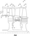
- FIG. 1 illustrates an example turbojet engine 10.
- the engine 10 generally includes a fan section 12, a compressor section 14, a combustor section 16, a turbine section 18, an augmentor section 19 and a nozzle section 20.
- the compressor section 14, combustor section 16 and turbine section 18 are generally referred to as the core engine.
- An axis A of the engine 10 extends longitudinally through the sections.
- An outer engine duct structure 22 and an inner cooling liner structure 24, or exhaust liner, provide an annular secondary fan bypass flow path 26 around a primary exhaust flow path E.
- the disclosed blade outer air seal may be used in commercial and industrial gas turbine engines as well.
- the examples described in this disclosure is not limited to a single-spool gas turbine and may be used in other architectures, such as a two-spool axial design, a three-spool axial design, and still other architectures. That is, there are various types of gas turbine engines, and other turbomachines, that can benefit from the examples disclosed herein.
- the example turbine section 18 includes multiple fixed stages 30a, 30b and multiple rotatable stages 32a, 32b, schematically shown in Figure 2 . Fewer or greater number of fixed and/or rotating stages may be used than depicted, if desired.
- One of the rotatable stages 32a includes a rotor 34 supporting a circumferential array of blades 36 for rotation about the axis A.
- Blade outer air seals (BOAS) 38 which are typically provided by multiple arcuate segments, are supported by the static structure of the engine to provide an annular gas seal relative to core gas flow C through the blades 36.
- the (BOAS) 38 includes forward and aft hooks 40, 42 used to secure the BOAS to the static structure.
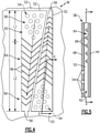
- the BOAS 38 includes a first wall 44 providing a sealing surface that provides a gas seal relative to a tip 46 of the blade 36.
- a second wall 48 is spaced from the first wall 44 and provides an outer wall that is in fluid communication with a cooling air supply 50.
- the cooling air supply may be provided by an upstream stage, such as air from the compressor section.
- One or more cooling passages 52 are provided in the BOAS 38 between the first and second walls 44, 48.
- the multiple cooling passages are provided parallel to one another and arranged in a first or circumferential direction.
- around six to ten cooling passages 52 may be provided in a blade outer air seal 38.
- a cluster of impingement inlet holes 54 is provided in the second wall 48 and is in fluid communication with the cooling air supply 50 to supply the cooling air to the cooling passages 52.
- the impingement holes 54 may be provided using a drilling or electro discharge machining process, for example.
- Outlets 56 are in fluid communication with the cooling passages 52 and may be provided in spaced apart lateral walls 53 that are next to circumferentially adjacent BOAS. The outlets 56 purge core gas flow from the gap between the adjacent BOAS.
- the cooling passage 52 extends a length L from a first end 58 to a second end 60.
- the outlet 56 is provided in the second end 60.
- First and second regions 62, 64 are respectively arranged at the first and second ends 58, 60.
- the impingement holes 54 is arranged at the first end 58 such that cooling air impinges upon the first wall 48 in the first region 62.
- the first region includes relatively smooth walls providing a Darcy friction factor of around 1.0.
- the first region extends along the cooling passage 52 a length L1 in the range of 25-65%, and in one example, 30-60%.
- Turbulators 66 are provided in the second region 64, which is arranged downstream from the impingement holes 54.
- the turbulators 66 are provided by an array of chevron-shaped protrusions extending from at least one of the first and second walls 44, 48.
- the turbulators 66 are provided on the first wall 44, which reduces the heat from the core gas flow path.
- the second region 64 extending a length L2, has higher friction factor than in the first region 62.
- the Darcy friction factor of the second region is around 8.4.
- the disclosed blade outer air seal cooling scheme may also be used in a compressor section, if desired, as well as other gas turbine engine components, such as vanes, blades, exhaust liners, combustor liners, or augmenter liners.
- the blade outer air seal reduces the friction losses within the cooling passages because first region 62 has lower fluid friction than in second region 64, as compared to prior art blade outer air seals.
- the cooling passage also provides a higher inlet area and reduces the flow restriction into the cooling passage. As a result, a reduced amount of supply pressure is needed for the same amount of cooling as compared to prior art cooling passages. Using a lower pressure cooling fluid reduces leakage and increases the cooling capacity for the same amount of cooling fluid flow.
Landscapes
- Engineering & Computer Science (AREA)
- Mechanical Engineering (AREA)
- General Engineering & Computer Science (AREA)
- Turbine Rotor Nozzle Sealing (AREA)
Claims (6)
- Gasturbinentriebwerkskomponente, die Folgendes umfasst:
eine Struktur, die eine erste Wand (44) und eine zweite Wand (48) beinhaltet, die einen Kühlkanal (52) bereitstellen, wobei sich der Kühlkanal (52) der Länge nach von einem ersten Ende (58) zu einem zweiten Ende (60) erstreckt, eine Gruppe von Aufpralleinlasslöchern (54) in der zweiten Wand an dem ersten Ende (58) bereitgestellt ist und ein Auslass (56) an dem zweiten Ende (60) bereitgestellt ist, ein erster Bereich (62) innerhalb des Kühlkanals (52) benachbart zu der Gruppe von Aufpralleinlasslöchern (54) bereitgestellt ist und ein zweiter Bereich (64) Turbulatoren (66) beinhaltet, wobei sich der erste Bereich (62) im Bereich von 25-65 % der Länge L erstreckt und aufgrund der Turbulatoren eine geringere Fluidreibung als der zweite Bereich (64) aufweist; dadurch gekennzeichnet, dass die Struktur mehrere einzelne Kühlkanäle (52) beinhaltet, die parallel zueinander bereitgestellt und in einer Umfangsrichtung angeordnet sind, wobei jeder den Auslass (56) und die Gruppe von Aufpralleinlasslöchern (54), die in der zweiten Wand (48) bereitgestellt ist, aufweist; und wobei die Struktur eine Schaufelaußendichtung (38) ist. - Gasturbinentriebwerkskomponente nach Anspruch 1, wobei der Kühlkanal (52) zwischen Seitenwänden (53) bereitgestellt ist und der Auslass (56) in einer der Seitenwände bereitgestellt ist.
- Gasturbinentriebwerkskomponente nach Anspruch 1, wobei die erste Wand (44) eine Dichtfläche beinhaltet und die zweite Wand (48) eine Außenwand bereitstellt, die dazu konfiguriert ist, mit einer Kühlquelle in Fluidverbindung zu stehen.
- Gasturbinentriebwerkskomponente nach einem der vorstehenden Ansprüche, wobei die Turbulatoren (66) in mindestens einer von der ersten und zweiten Wand beinhaltet und stromabwärts des Einlasslochs (54) in der zweiten Wand (48) angeordnet sind.
- Gasturbinentriebwerkskomponente nach Anspruch 4, wobei die Turbulatoren (66) Zickzackleisten sind.
- Gasturbinentriebwerkskomponente nach Anspruch 4, wobei der zweite Bereich (64) einen Darcy-Reibungsfaktor aufweist, der aufgrund der Turbulatoren (66) höher als ein Darcy-Reibungsfaktor des ersten Bereichs (62) ist, und wobei mehr bevorzugt der erste Bereich (62) einen Darcy-Reibungsfaktor von ungefähr 1,0 aufweist und der zweite Bereich (64) einen Darcy-Reibungsfaktor von ungefähr 8,4 aufweist.
Applications Claiming Priority (2)
| Application Number | Priority Date | Filing Date | Title |
|---|---|---|---|
| US201361918249P | 2013-12-19 | 2013-12-19 | |
| PCT/US2014/069570 WO2015130380A2 (en) | 2013-12-19 | 2014-12-10 | Blade outer air seal cooling passage |
Publications (3)
| Publication Number | Publication Date |
|---|---|
| EP3084184A2 EP3084184A2 (de) | 2016-10-26 |
| EP3084184A4 EP3084184A4 (de) | 2017-09-13 |
| EP3084184B1 true EP3084184B1 (de) | 2022-03-23 |
Family
ID=54009752
Family Applications (1)
| Application Number | Title | Priority Date | Filing Date |
|---|---|---|---|
| EP14883695.0A Active EP3084184B1 (de) | 2013-12-19 | 2014-12-10 | Kühlkanal für schaufelaussendichtung |
Country Status (3)
| Country | Link |
|---|---|
| US (1) | US10309255B2 (de) |
| EP (1) | EP3084184B1 (de) |
| WO (1) | WO2015130380A2 (de) |
Families Citing this family (6)
| Publication number | Priority date | Publication date | Assignee | Title |
|---|---|---|---|---|
| US10690055B2 (en) * | 2014-05-29 | 2020-06-23 | General Electric Company | Engine components with impingement cooling features |
| US10060288B2 (en) | 2015-10-09 | 2018-08-28 | United Technologies Corporation | Multi-flow cooling passage chamber for gas turbine engine |
| US10801345B2 (en) | 2016-02-09 | 2020-10-13 | Raytheon Technologies Corporation | Chevron trip strip |
| US10202864B2 (en) * | 2016-02-09 | 2019-02-12 | United Technologies Corporation | Chevron trip strip |
| US20170260873A1 (en) * | 2016-03-10 | 2017-09-14 | General Electric Company | System and method for cooling trailing edge and/or leading edge of hot gas flow path component |
| US11193386B2 (en) | 2016-05-18 | 2021-12-07 | Raytheon Technologies Corporation | Shaped cooling passages for turbine blade outer air seal |
Citations (2)
| Publication number | Priority date | Publication date | Assignee | Title |
|---|---|---|---|---|
| US20030131980A1 (en) * | 2002-01-16 | 2003-07-17 | General Electric Company | Multiple impingement cooled structure |
| EP2469034A2 (de) * | 2010-12-22 | 2012-06-27 | United Technologies Corporation | Turbinenleitschaufel mit einer Plattform mit Kühlkreislauf und zugehöriges Herstellungsverfahren |
Family Cites Families (28)
| Publication number | Priority date | Publication date | Assignee | Title |
|---|---|---|---|---|
| US4573865A (en) * | 1981-08-31 | 1986-03-04 | General Electric Company | Multiple-impingement cooled structure |
| US5092735A (en) * | 1990-07-02 | 1992-03-03 | The United States Of America As Represented By The Secretary Of The Air Force | Blade outer air seal cooling system |
| JPH0552102A (ja) | 1991-08-23 | 1993-03-02 | Toshiba Corp | ガスタービン |
| US5375973A (en) * | 1992-12-23 | 1994-12-27 | United Technologies Corporation | Turbine blade outer air seal with optimized cooling |
| US5391052A (en) * | 1993-11-16 | 1995-02-21 | General Electric Co. | Impingement cooling and cooling medium retrieval system for turbine shrouds and methods of operation |
| US6924002B2 (en) | 2003-02-24 | 2005-08-02 | General Electric Company | Coating and coating process incorporating raised surface features for an air-cooled surface |
| US7306424B2 (en) * | 2004-12-29 | 2007-12-11 | United Technologies Corporation | Blade outer seal with micro axial flow cooling system |
| US7284954B2 (en) * | 2005-02-17 | 2007-10-23 | Parker David G | Shroud block with enhanced cooling |
| US20070020088A1 (en) * | 2005-07-20 | 2007-01-25 | Pratt & Whitney Canada Corp. | Turbine shroud segment impingement cooling on vane outer shroud |
| US7513040B2 (en) | 2005-08-31 | 2009-04-07 | United Technologies Corporation | Manufacturable and inspectable cooling microcircuits for blade-outer-air-seals |
| US7621719B2 (en) | 2005-09-30 | 2009-11-24 | United Technologies Corporation | Multiple cooling schemes for turbine blade outer air seal |
| US7686068B2 (en) * | 2006-08-10 | 2010-03-30 | United Technologies Corporation | Blade outer air seal cores and manufacture methods |
| US7650926B2 (en) | 2006-09-28 | 2010-01-26 | United Technologies Corporation | Blade outer air seals, cores, and manufacture methods |
| US7553128B2 (en) | 2006-10-12 | 2009-06-30 | United Technologies Corporation | Blade outer air seals |
| US7670108B2 (en) * | 2006-11-21 | 2010-03-02 | Siemens Energy, Inc. | Air seal unit adapted to be positioned adjacent blade structure in a gas turbine |
| US8439629B2 (en) | 2007-03-01 | 2013-05-14 | United Technologies Corporation | Blade outer air seal |
| US8123466B2 (en) * | 2007-03-01 | 2012-02-28 | United Technologies Corporation | Blade outer air seal |
| US8177492B2 (en) | 2008-03-04 | 2012-05-15 | United Technologies Corporation | Passage obstruction for improved inlet coolant filling |
| CA2712758C (en) | 2009-08-18 | 2017-12-05 | Pratt & Whitney Canada Corp. | Blade outer air seal support cooling air distribution system |
| CA2713284C (en) | 2009-08-18 | 2017-09-19 | Pratt & Whitney Canada Corp. | Blade outer air seal cooling |
| WO2011020485A1 (en) | 2009-08-20 | 2011-02-24 | Siemens Aktiengesellschaft | Cross-flow blockers in a gas turbine impingement cooling gap |
| US8876458B2 (en) | 2011-01-25 | 2014-11-04 | United Technologies Corporation | Blade outer air seal assembly and support |
| US8931280B2 (en) * | 2011-04-26 | 2015-01-13 | General Electric Company | Fully impingement cooled venturi with inbuilt resonator for reduced dynamics and better heat transfer capabilities |
| US9238970B2 (en) | 2011-09-19 | 2016-01-19 | United Technologies Corporation | Blade outer air seal assembly leading edge core configuration |
| US9217568B2 (en) | 2012-06-07 | 2015-12-22 | United Technologies Corporation | Combustor liner with decreased liner cooling |
| US9500099B2 (en) | 2012-07-02 | 2016-11-22 | United Techologies Corporation | Cover plate for a component of a gas turbine engine |
| US9194585B2 (en) | 2012-10-04 | 2015-11-24 | United Technologies Corporation | Cooling for combustor liners with accelerating channels |
| US10215051B2 (en) | 2013-08-20 | 2019-02-26 | United Technologies Corporation | Gas turbine engine component providing prioritized cooling |
-
2014
- 2014-12-10 EP EP14883695.0A patent/EP3084184B1/de active Active
- 2014-12-10 WO PCT/US2014/069570 patent/WO2015130380A2/en active Application Filing
- 2014-12-10 US US15/104,092 patent/US10309255B2/en active Active
Patent Citations (2)
| Publication number | Priority date | Publication date | Assignee | Title |
|---|---|---|---|---|
| US20030131980A1 (en) * | 2002-01-16 | 2003-07-17 | General Electric Company | Multiple impingement cooled structure |
| EP2469034A2 (de) * | 2010-12-22 | 2012-06-27 | United Technologies Corporation | Turbinenleitschaufel mit einer Plattform mit Kühlkreislauf und zugehöriges Herstellungsverfahren |
Also Published As
| Publication number | Publication date |
|---|---|
| WO2015130380A3 (en) | 2015-10-29 |
| US20160319698A1 (en) | 2016-11-03 |
| EP3084184A2 (de) | 2016-10-26 |
| EP3084184A4 (de) | 2017-09-13 |
| WO2015130380A2 (en) | 2015-09-03 |
| US10309255B2 (en) | 2019-06-04 |
Similar Documents
| Publication | Publication Date | Title |
|---|---|---|
| EP3092373B1 (de) | System mit einer messplatte und einer aussenluftdichtung für eine turbinenschaufel | |
| EP3084184B1 (de) | Kühlkanal für schaufelaussendichtung | |
| EP2855891B1 (de) | Äussere laufschaufelluftdichtung für einen gasturbinenmotor | |
| EP2820272B1 (de) | Pufferkühlsystem mit motorarchitekturkühlung für gasturbinen | |
| EP2907978B1 (de) | Turbinenzwischengehäuse mit definiertem Kühlmittelverteilungsfluss | |
| US20170051623A1 (en) | Cooling channels for gas turbine engine component | |
| US9151226B2 (en) | Corrugated mid-turbine frame thermal radiation shield | |
| US9988934B2 (en) | Gas turbine engines including channel-cooled hooks for retaining a part relative to an engine casing structure | |
| US9303528B2 (en) | Mid-turbine frame thermal radiation shield | |
| US10738791B2 (en) | Active high pressure compressor clearance control | |
| US10221767B2 (en) | Actively cooled blade outer air seal | |
| EP3214274B1 (de) | Eingekapselte kühlung für turbinenummantelungen | |
| EP3023594B1 (de) | Statoranordnung mit pad-schnittstelle für eine gasturbine | |
| US9945239B2 (en) | Vane carrier for a compressor or a turbine section of an axial turbo machine | |
| WO2015020806A1 (en) | Airfoil trailing edge tip cooling | |
| US9995172B2 (en) | Turbine nozzle with cooling channel coolant discharge plenum | |
| EP2551468A1 (de) | Anordnung einer Schaufelspitzendichtung mit durchgangsverbundenen Hohlräumen und zugehöriges Betriebsverfahren | |
| EP3008309B1 (de) | Flusssteuerungsvorrichtung für einen gasturbinenmotor | |
| EP3196408B1 (de) | Gasturbinenmotor mit einem abschnitt mit wärmeisoliertem bereich | |
| EP3181828B1 (de) | Äussere laufschaufeldichtung mit integrierter luftisolierung | |
| EP3159492B1 (de) | Kühlkanäle für gasturbinenmotorkomponente |
Legal Events
| Date | Code | Title | Description |
|---|---|---|---|
| PUAI | Public reference made under article 153(3) epc to a published international application that has entered the european phase |
Free format text: ORIGINAL CODE: 0009012 |
|
| 17P | Request for examination filed |
Effective date: 20160719 |
|
| AK | Designated contracting states |
Kind code of ref document: A2 Designated state(s): AL AT BE BG CH CY CZ DE DK EE ES FI FR GB GR HR HU IE IS IT LI LT LU LV MC MK MT NL NO PL PT RO RS SE SI SK SM TR |
|
| AX | Request for extension of the european patent |
Extension state: BA ME |
|
| DAX | Request for extension of the european patent (deleted) | ||
| REG | Reference to a national code |
Ref country code: DE Ref legal event code: R079 Ref document number: 602014082967 Country of ref document: DE Free format text: PREVIOUS MAIN CLASS: F02C0007180000 Ipc: F01D0011080000 |
|
| A4 | Supplementary search report drawn up and despatched |
Effective date: 20170814 |
|
| RIC1 | Information provided on ipc code assigned before grant |
Ipc: F01D 11/08 20060101AFI20170808BHEP Ipc: F01D 25/12 20060101ALI20170808BHEP |
|
| STAA | Information on the status of an ep patent application or granted ep patent |
Free format text: STATUS: EXAMINATION IS IN PROGRESS |
|
| 17Q | First examination report despatched |
Effective date: 20200708 |
|
| STAA | Information on the status of an ep patent application or granted ep patent |
Free format text: STATUS: EXAMINATION IS IN PROGRESS |
|
| RAP1 | Party data changed (applicant data changed or rights of an application transferred) |
Owner name: RAYTHEON TECHNOLOGIES CORPORATION |
|
| GRAP | Despatch of communication of intention to grant a patent |
Free format text: ORIGINAL CODE: EPIDOSNIGR1 |
|
| STAA | Information on the status of an ep patent application or granted ep patent |
Free format text: STATUS: GRANT OF PATENT IS INTENDED |
|
| INTG | Intention to grant announced |
Effective date: 20211110 |
|
| GRAS | Grant fee paid |
Free format text: ORIGINAL CODE: EPIDOSNIGR3 |
|
| GRAA | (expected) grant |
Free format text: ORIGINAL CODE: 0009210 |
|
| STAA | Information on the status of an ep patent application or granted ep patent |
Free format text: STATUS: THE PATENT HAS BEEN GRANTED |
|
| AK | Designated contracting states |
Kind code of ref document: B1 Designated state(s): AL AT BE BG CH CY CZ DE DK EE ES FI FR GB GR HR HU IE IS IT LI LT LU LV MC MK MT NL NO PL PT RO RS SE SI SK SM TR |
|
| REG | Reference to a national code |
Ref country code: GB Ref legal event code: FG4D |
|
| REG | Reference to a national code |
Ref country code: CH Ref legal event code: EP |
|
| REG | Reference to a national code |
Ref country code: IE Ref legal event code: FG4D |
|
| REG | Reference to a national code |
Ref country code: DE Ref legal event code: R096 Ref document number: 602014082967 Country of ref document: DE |
|
| REG | Reference to a national code |
Ref country code: AT Ref legal event code: REF Ref document number: 1477564 Country of ref document: AT Kind code of ref document: T Effective date: 20220415 |
|
| REG | Reference to a national code |
Ref country code: LT Ref legal event code: MG9D |
|
| REG | Reference to a national code |
Ref country code: NL Ref legal event code: MP Effective date: 20220323 |
|
| PG25 | Lapsed in a contracting state [announced via postgrant information from national office to epo] |
Ref country code: SE Free format text: LAPSE BECAUSE OF FAILURE TO SUBMIT A TRANSLATION OF THE DESCRIPTION OR TO PAY THE FEE WITHIN THE PRESCRIBED TIME-LIMIT Effective date: 20220323 Ref country code: RS Free format text: LAPSE BECAUSE OF FAILURE TO SUBMIT A TRANSLATION OF THE DESCRIPTION OR TO PAY THE FEE WITHIN THE PRESCRIBED TIME-LIMIT Effective date: 20220323 Ref country code: NO Free format text: LAPSE BECAUSE OF FAILURE TO SUBMIT A TRANSLATION OF THE DESCRIPTION OR TO PAY THE FEE WITHIN THE PRESCRIBED TIME-LIMIT Effective date: 20220623 Ref country code: LT Free format text: LAPSE BECAUSE OF FAILURE TO SUBMIT A TRANSLATION OF THE DESCRIPTION OR TO PAY THE FEE WITHIN THE PRESCRIBED TIME-LIMIT Effective date: 20220323 Ref country code: HR Free format text: LAPSE BECAUSE OF FAILURE TO SUBMIT A TRANSLATION OF THE DESCRIPTION OR TO PAY THE FEE WITHIN THE PRESCRIBED TIME-LIMIT Effective date: 20220323 Ref country code: BG Free format text: LAPSE BECAUSE OF FAILURE TO SUBMIT A TRANSLATION OF THE DESCRIPTION OR TO PAY THE FEE WITHIN THE PRESCRIBED TIME-LIMIT Effective date: 20220623 |
|
| REG | Reference to a national code |
Ref country code: AT Ref legal event code: MK05 Ref document number: 1477564 Country of ref document: AT Kind code of ref document: T Effective date: 20220323 |
|
| PG25 | Lapsed in a contracting state [announced via postgrant information from national office to epo] |
Ref country code: LV Free format text: LAPSE BECAUSE OF FAILURE TO SUBMIT A TRANSLATION OF THE DESCRIPTION OR TO PAY THE FEE WITHIN THE PRESCRIBED TIME-LIMIT Effective date: 20220323 Ref country code: GR Free format text: LAPSE BECAUSE OF FAILURE TO SUBMIT A TRANSLATION OF THE DESCRIPTION OR TO PAY THE FEE WITHIN THE PRESCRIBED TIME-LIMIT Effective date: 20220624 Ref country code: FI Free format text: LAPSE BECAUSE OF FAILURE TO SUBMIT A TRANSLATION OF THE DESCRIPTION OR TO PAY THE FEE WITHIN THE PRESCRIBED TIME-LIMIT Effective date: 20220323 |
|
| PG25 | Lapsed in a contracting state [announced via postgrant information from national office to epo] |
Ref country code: NL Free format text: LAPSE BECAUSE OF FAILURE TO SUBMIT A TRANSLATION OF THE DESCRIPTION OR TO PAY THE FEE WITHIN THE PRESCRIBED TIME-LIMIT Effective date: 20220323 |
|
| PG25 | Lapsed in a contracting state [announced via postgrant information from national office to epo] |
Ref country code: SM Free format text: LAPSE BECAUSE OF FAILURE TO SUBMIT A TRANSLATION OF THE DESCRIPTION OR TO PAY THE FEE WITHIN THE PRESCRIBED TIME-LIMIT Effective date: 20220323 Ref country code: SK Free format text: LAPSE BECAUSE OF FAILURE TO SUBMIT A TRANSLATION OF THE DESCRIPTION OR TO PAY THE FEE WITHIN THE PRESCRIBED TIME-LIMIT Effective date: 20220323 Ref country code: RO Free format text: LAPSE BECAUSE OF FAILURE TO SUBMIT A TRANSLATION OF THE DESCRIPTION OR TO PAY THE FEE WITHIN THE PRESCRIBED TIME-LIMIT Effective date: 20220323 Ref country code: PT Free format text: LAPSE BECAUSE OF FAILURE TO SUBMIT A TRANSLATION OF THE DESCRIPTION OR TO PAY THE FEE WITHIN THE PRESCRIBED TIME-LIMIT Effective date: 20220725 Ref country code: ES Free format text: LAPSE BECAUSE OF FAILURE TO SUBMIT A TRANSLATION OF THE DESCRIPTION OR TO PAY THE FEE WITHIN THE PRESCRIBED TIME-LIMIT Effective date: 20220323 Ref country code: EE Free format text: LAPSE BECAUSE OF FAILURE TO SUBMIT A TRANSLATION OF THE DESCRIPTION OR TO PAY THE FEE WITHIN THE PRESCRIBED TIME-LIMIT Effective date: 20220323 Ref country code: CZ Free format text: LAPSE BECAUSE OF FAILURE TO SUBMIT A TRANSLATION OF THE DESCRIPTION OR TO PAY THE FEE WITHIN THE PRESCRIBED TIME-LIMIT Effective date: 20220323 Ref country code: AT Free format text: LAPSE BECAUSE OF FAILURE TO SUBMIT A TRANSLATION OF THE DESCRIPTION OR TO PAY THE FEE WITHIN THE PRESCRIBED TIME-LIMIT Effective date: 20220323 |
|
| PG25 | Lapsed in a contracting state [announced via postgrant information from national office to epo] |
Ref country code: PL Free format text: LAPSE BECAUSE OF FAILURE TO SUBMIT A TRANSLATION OF THE DESCRIPTION OR TO PAY THE FEE WITHIN THE PRESCRIBED TIME-LIMIT Effective date: 20220323 Ref country code: IS Free format text: LAPSE BECAUSE OF FAILURE TO SUBMIT A TRANSLATION OF THE DESCRIPTION OR TO PAY THE FEE WITHIN THE PRESCRIBED TIME-LIMIT Effective date: 20220723 Ref country code: AL Free format text: LAPSE BECAUSE OF FAILURE TO SUBMIT A TRANSLATION OF THE DESCRIPTION OR TO PAY THE FEE WITHIN THE PRESCRIBED TIME-LIMIT Effective date: 20220323 |
|
| REG | Reference to a national code |
Ref country code: DE Ref legal event code: R097 Ref document number: 602014082967 Country of ref document: DE |
|
| PLBE | No opposition filed within time limit |
Free format text: ORIGINAL CODE: 0009261 |
|
| STAA | Information on the status of an ep patent application or granted ep patent |
Free format text: STATUS: NO OPPOSITION FILED WITHIN TIME LIMIT |
|
| PG25 | Lapsed in a contracting state [announced via postgrant information from national office to epo] |
Ref country code: DK Free format text: LAPSE BECAUSE OF FAILURE TO SUBMIT A TRANSLATION OF THE DESCRIPTION OR TO PAY THE FEE WITHIN THE PRESCRIBED TIME-LIMIT Effective date: 20220323 |
|
| 26N | No opposition filed |
Effective date: 20230102 |
|
| PG25 | Lapsed in a contracting state [announced via postgrant information from national office to epo] |
Ref country code: SI Free format text: LAPSE BECAUSE OF FAILURE TO SUBMIT A TRANSLATION OF THE DESCRIPTION OR TO PAY THE FEE WITHIN THE PRESCRIBED TIME-LIMIT Effective date: 20220323 |
|
| P01 | Opt-out of the competence of the unified patent court (upc) registered |
Effective date: 20230520 |
|
| PG25 | Lapsed in a contracting state [announced via postgrant information from national office to epo] |
Ref country code: IT Free format text: LAPSE BECAUSE OF FAILURE TO SUBMIT A TRANSLATION OF THE DESCRIPTION OR TO PAY THE FEE WITHIN THE PRESCRIBED TIME-LIMIT Effective date: 20220323 |
|
| REG | Reference to a national code |
Ref country code: CH Ref legal event code: PL |
|
| REG | Reference to a national code |
Ref country code: BE Ref legal event code: MM Effective date: 20221231 |
|
| PG25 | Lapsed in a contracting state [announced via postgrant information from national office to epo] |
Ref country code: LU Free format text: LAPSE BECAUSE OF NON-PAYMENT OF DUE FEES Effective date: 20221210 |
|
| PG25 | Lapsed in a contracting state [announced via postgrant information from national office to epo] |
Ref country code: LI Free format text: LAPSE BECAUSE OF NON-PAYMENT OF DUE FEES Effective date: 20221231 Ref country code: IE Free format text: LAPSE BECAUSE OF NON-PAYMENT OF DUE FEES Effective date: 20221210 Ref country code: CH Free format text: LAPSE BECAUSE OF NON-PAYMENT OF DUE FEES Effective date: 20221231 |
|
| PG25 | Lapsed in a contracting state [announced via postgrant information from national office to epo] |
Ref country code: BE Free format text: LAPSE BECAUSE OF NON-PAYMENT OF DUE FEES Effective date: 20221231 |
|
| PGFP | Annual fee paid to national office [announced via postgrant information from national office to epo] |
Ref country code: GB Payment date: 20231121 Year of fee payment: 10 |
|
| PGFP | Annual fee paid to national office [announced via postgrant information from national office to epo] |
Ref country code: FR Payment date: 20231122 Year of fee payment: 10 Ref country code: DE Payment date: 20231121 Year of fee payment: 10 |
|
| PG25 | Lapsed in a contracting state [announced via postgrant information from national office to epo] |
Ref country code: HU Free format text: LAPSE BECAUSE OF FAILURE TO SUBMIT A TRANSLATION OF THE DESCRIPTION OR TO PAY THE FEE WITHIN THE PRESCRIBED TIME-LIMIT; INVALID AB INITIO Effective date: 20141210 |
|
| PG25 | Lapsed in a contracting state [announced via postgrant information from national office to epo] |
Ref country code: CY Free format text: LAPSE BECAUSE OF FAILURE TO SUBMIT A TRANSLATION OF THE DESCRIPTION OR TO PAY THE FEE WITHIN THE PRESCRIBED TIME-LIMIT Effective date: 20220323 |
|
| PG25 | Lapsed in a contracting state [announced via postgrant information from national office to epo] |
Ref country code: MK Free format text: LAPSE BECAUSE OF FAILURE TO SUBMIT A TRANSLATION OF THE DESCRIPTION OR TO PAY THE FEE WITHIN THE PRESCRIBED TIME-LIMIT Effective date: 20220323 |
|
| PG25 | Lapsed in a contracting state [announced via postgrant information from national office to epo] |
Ref country code: MC Free format text: LAPSE BECAUSE OF FAILURE TO SUBMIT A TRANSLATION OF THE DESCRIPTION OR TO PAY THE FEE WITHIN THE PRESCRIBED TIME-LIMIT Effective date: 20220323 |
|
| PG25 | Lapsed in a contracting state [announced via postgrant information from national office to epo] |
Ref country code: MC Free format text: LAPSE BECAUSE OF FAILURE TO SUBMIT A TRANSLATION OF THE DESCRIPTION OR TO PAY THE FEE WITHIN THE PRESCRIBED TIME-LIMIT Effective date: 20220323 |