EP3083492B1 - Method for purifying synthesis gas by amine scrubbing using aqueous amine solutions - Google Patents
Method for purifying synthesis gas by amine scrubbing using aqueous amine solutions Download PDFInfo
- Publication number
- EP3083492B1 EP3083492B1 EP14824421.3A EP14824421A EP3083492B1 EP 3083492 B1 EP3083492 B1 EP 3083492B1 EP 14824421 A EP14824421 A EP 14824421A EP 3083492 B1 EP3083492 B1 EP 3083492B1
- Authority
- EP
- European Patent Office
- Prior art keywords
- stage
- amino
- methyl
- methoxypropyl
- synthesis gas
- Prior art date
- Legal status (The legal status is an assumption and is not a legal conclusion. Google has not performed a legal analysis and makes no representation as to the accuracy of the status listed.)
- Active
Links
- 238000003786 synthesis reaction Methods 0.000 title claims description 130
- 230000015572 biosynthetic process Effects 0.000 title claims description 128
- 238000000034 method Methods 0.000 title claims description 71
- 150000001412 amines Chemical class 0.000 title claims description 67
- 238000005201 scrubbing Methods 0.000 title 1
- 239000007789 gas Substances 0.000 claims description 225
- 239000003054 catalyst Substances 0.000 claims description 68
- 230000008569 process Effects 0.000 claims description 58
- 229910002091 carbon monoxide Inorganic materials 0.000 claims description 54
- 239000002253 acid Substances 0.000 claims description 50
- 239000000203 mixture Substances 0.000 claims description 50
- 239000002904 solvent Substances 0.000 claims description 45
- 238000006243 chemical reaction Methods 0.000 claims description 44
- 150000003335 secondary amines Chemical class 0.000 claims description 44
- CRVGTESFCCXCTH-UHFFFAOYSA-N methyl diethanolamine Chemical compound OCCN(C)CCO CRVGTESFCCXCTH-UHFFFAOYSA-N 0.000 claims description 41
- 239000007864 aqueous solution Substances 0.000 claims description 36
- UGFAIRIUMAVXCW-UHFFFAOYSA-N Carbon monoxide Chemical compound [O+]#[C-] UGFAIRIUMAVXCW-UHFFFAOYSA-N 0.000 claims description 34
- 238000006460 hydrolysis reaction Methods 0.000 claims description 33
- 230000007062 hydrolysis Effects 0.000 claims description 32
- GLUUGHFHXGJENI-UHFFFAOYSA-N Piperazine Chemical compound C1CNCCN1 GLUUGHFHXGJENI-UHFFFAOYSA-N 0.000 claims description 30
- 230000003197 catalytic effect Effects 0.000 claims description 29
- CURLTUGMZLYLDI-UHFFFAOYSA-N Carbon dioxide Chemical compound O=C=O CURLTUGMZLYLDI-UHFFFAOYSA-N 0.000 claims description 27
- 238000010521 absorption reaction Methods 0.000 claims description 26
- 230000008929 regeneration Effects 0.000 claims description 25
- 238000011069 regeneration method Methods 0.000 claims description 25
- 150000003512 tertiary amines Chemical class 0.000 claims description 23
- 238000000746 purification Methods 0.000 claims description 21
- 150000003141 primary amines Chemical class 0.000 claims description 19
- 229910002092 carbon dioxide Inorganic materials 0.000 claims description 15
- 150000001875 compounds Chemical class 0.000 claims description 14
- 229910052739 hydrogen Inorganic materials 0.000 claims description 14
- ZBCBWPMODOFKDW-UHFFFAOYSA-N diethanolamine Chemical compound OCCNCCO ZBCBWPMODOFKDW-UHFFFAOYSA-N 0.000 claims description 13
- YNAVUWVOSKDBBP-UHFFFAOYSA-N Morpholine Chemical compound C1COCCN1 YNAVUWVOSKDBBP-UHFFFAOYSA-N 0.000 claims description 12
- 239000001257 hydrogen Substances 0.000 claims description 12
- 238000005215 recombination Methods 0.000 claims description 12
- 230000006798 recombination Effects 0.000 claims description 12
- 239000001569 carbon dioxide Substances 0.000 claims description 11
- HZAXFHJVJLSVMW-UHFFFAOYSA-N 2-Aminoethan-1-ol Chemical compound NCCO HZAXFHJVJLSVMW-UHFFFAOYSA-N 0.000 claims description 9
- 229910052757 nitrogen Inorganic materials 0.000 claims description 9
- VYPSYNLAJGMNEJ-UHFFFAOYSA-N Silicium dioxide Chemical compound O=[Si]=O VYPSYNLAJGMNEJ-UHFFFAOYSA-N 0.000 claims description 8
- BFSVOASYOCHEOV-UHFFFAOYSA-N 2-diethylaminoethanol Chemical compound CCN(CC)CCO BFSVOASYOCHEOV-UHFFFAOYSA-N 0.000 claims description 7
- 239000012190 activator Substances 0.000 claims description 7
- FKYPMBVSLXIHKN-UHFFFAOYSA-N 1-[1-(dimethylamino)ethoxy]-n,n-dimethylpropan-1-amine Chemical compound CCC(N(C)C)OC(C)N(C)C FKYPMBVSLXIHKN-UHFFFAOYSA-N 0.000 claims description 6
- GSEJCLTVZPLZKY-UHFFFAOYSA-N Triethanolamine Chemical compound OCCN(CCO)CCO GSEJCLTVZPLZKY-UHFFFAOYSA-N 0.000 claims description 6
- 229910052799 carbon Inorganic materials 0.000 claims description 6
- 150000002431 hydrogen Chemical class 0.000 claims description 6
- GIAFURWZWWWBQT-UHFFFAOYSA-N 2-(2-aminoethoxy)ethanol Chemical compound NCCOCCO GIAFURWZWWWBQT-UHFFFAOYSA-N 0.000 claims description 5
- HXXJMMLIEYAFOZ-UHFFFAOYSA-N (1-methylpiperidin-2-yl)methanol Chemical compound CN1CCCCC1CO HXXJMMLIEYAFOZ-UHFFFAOYSA-N 0.000 claims description 4
- PVOAHINGSUIXLS-UHFFFAOYSA-N 1-Methylpiperazine Chemical compound CN1CCNCC1 PVOAHINGSUIXLS-UHFFFAOYSA-N 0.000 claims description 4
- TWTKUWBQBMZUQN-UHFFFAOYSA-N 1-[(1-hydroxy-2-methylpropan-2-yl)amino]butan-2-ol Chemical compound CCC(O)CNC(C)(C)CO TWTKUWBQBMZUQN-UHFFFAOYSA-N 0.000 claims description 4
- ITGHNAXRIAXHEW-UHFFFAOYSA-N 1-[1-(diethylamino)ethoxy]-n,n-diethylpropan-1-amine Chemical compound CCN(CC)C(CC)OC(C)N(CC)CC ITGHNAXRIAXHEW-UHFFFAOYSA-N 0.000 claims description 4
- KBCPTAAJBVKTGN-UHFFFAOYSA-N 1-[1-(diethylamino)propoxy]-n,n-diethylpropan-1-amine Chemical compound CCN(CC)C(CC)OC(CC)N(CC)CC KBCPTAAJBVKTGN-UHFFFAOYSA-N 0.000 claims description 4
- DAQLTHSBAULVFD-UHFFFAOYSA-N 1-[1-(dimethylamino)propoxy]-n,n-dimethylpropan-1-amine Chemical compound CCC(N(C)C)OC(CC)N(C)C DAQLTHSBAULVFD-UHFFFAOYSA-N 0.000 claims description 4
- MWTQTGOEIKHJOO-UHFFFAOYSA-N 1-[3-methoxypropyl(methyl)amino]butan-2-ol Chemical compound CCC(O)CN(C)CCCOC MWTQTGOEIKHJOO-UHFFFAOYSA-N 0.000 claims description 4
- JMKLULSOUGXLNQ-UHFFFAOYSA-N 1-[3-methoxypropyl(methyl)amino]propan-2-ol Chemical compound COCCCN(C)CC(C)O JMKLULSOUGXLNQ-UHFFFAOYSA-N 0.000 claims description 4
- RBKGYEFADSPWKR-UHFFFAOYSA-N 1-[3-methoxypropyl(propan-2-yl)amino]butan-2-ol Chemical compound CCC(O)CN(C(C)C)CCCOC RBKGYEFADSPWKR-UHFFFAOYSA-N 0.000 claims description 4
- UWONXFNBQRSONX-UHFFFAOYSA-N 1-[3-methoxypropyl(propan-2-yl)amino]propan-2-ol Chemical compound COCCCN(C(C)C)CC(C)O UWONXFNBQRSONX-UHFFFAOYSA-N 0.000 claims description 4
- GRLCJJZSUVUVPA-UHFFFAOYSA-N 1-[ethyl(3-methoxypropyl)amino]butan-2-ol Chemical compound CCC(O)CN(CC)CCCOC GRLCJJZSUVUVPA-UHFFFAOYSA-N 0.000 claims description 4
- LKXYKBZBAPYPAE-UHFFFAOYSA-N 1-[ethyl(3-methoxypropyl)amino]propan-2-ol Chemical compound CC(O)CN(CC)CCCOC LKXYKBZBAPYPAE-UHFFFAOYSA-N 0.000 claims description 4
- BAUWRHPMUVYFOD-UHFFFAOYSA-N 1-methylpiperidin-4-ol Chemical compound CN1CCC(O)CC1 BAUWRHPMUVYFOD-UHFFFAOYSA-N 0.000 claims description 4
- GRLBHPWORYJVEH-UHFFFAOYSA-N 2-(2-hydroxyethylamino)-2-methylpropan-1-ol Chemical compound OCC(C)(C)NCCO GRLBHPWORYJVEH-UHFFFAOYSA-N 0.000 claims description 4
- OIULAVWJXFTBCQ-UHFFFAOYSA-N 2-(2-hydroxypropylamino)-2-methylpropan-1-ol Chemical compound CC(O)CNC(C)(C)CO OIULAVWJXFTBCQ-UHFFFAOYSA-N 0.000 claims description 4
- DMNIJELRGYXPHM-UHFFFAOYSA-N 2-[2-[2-(dimethylamino)ethoxy]ethoxy]-n,n-dimethylethanamine Chemical compound CN(C)CCOCCOCCN(C)C DMNIJELRGYXPHM-UHFFFAOYSA-N 0.000 claims description 4
- UPLLLBNFTFRBAT-UHFFFAOYSA-N 2-[3-methoxypropyl(methyl)amino]ethanol Chemical compound COCCCN(C)CCO UPLLLBNFTFRBAT-UHFFFAOYSA-N 0.000 claims description 4
- YWGIGTMIMJIXMS-UHFFFAOYSA-N 2-[3-methoxypropyl(propan-2-yl)amino]ethanol Chemical compound COCCCN(C(C)C)CCO YWGIGTMIMJIXMS-UHFFFAOYSA-N 0.000 claims description 4
- RPGKWTGKGKGYPY-UHFFFAOYSA-N 2-[ethyl(3-methoxypropyl)amino]ethanol Chemical compound OCCN(CC)CCCOC RPGKWTGKGKGYPY-UHFFFAOYSA-N 0.000 claims description 4
- XHJGXOOOMKCJPP-UHFFFAOYSA-N 2-[tert-butyl(2-hydroxyethyl)amino]ethanol Chemical compound OCCN(C(C)(C)C)CCO XHJGXOOOMKCJPP-UHFFFAOYSA-N 0.000 claims description 4
- UEEJHVSXFDXPFK-UHFFFAOYSA-N N-dimethylaminoethanol Chemical compound CN(C)CCO UEEJHVSXFDXPFK-UHFFFAOYSA-N 0.000 claims description 4
- AKNUHUCEWALCOI-UHFFFAOYSA-N N-ethyldiethanolamine Chemical compound OCCN(CC)CCO AKNUHUCEWALCOI-UHFFFAOYSA-N 0.000 claims description 4
- NQRYJNQNLNOLGT-UHFFFAOYSA-N Piperidine Chemical compound C1CCNCC1 NQRYJNQNLNOLGT-UHFFFAOYSA-N 0.000 claims description 4
- LHIJANUOQQMGNT-UHFFFAOYSA-N aminoethylethanolamine Chemical compound NCCNCCO LHIJANUOQQMGNT-UHFFFAOYSA-N 0.000 claims description 4
- 229960002887 deanol Drugs 0.000 claims description 4
- LVTYICIALWPMFW-UHFFFAOYSA-N diisopropanolamine Chemical compound CC(O)CNCC(C)O LVTYICIALWPMFW-UHFFFAOYSA-N 0.000 claims description 4
- 229940043276 diisopropanolamine Drugs 0.000 claims description 4
- 239000012972 dimethylethanolamine Substances 0.000 claims description 4
- JWPGWMIGNNGJOQ-UHFFFAOYSA-N n,n-diethyl-2-(4-ethylpiperazin-1-yl)ethanamine Chemical compound CCN(CC)CCN1CCN(CC)CC1 JWPGWMIGNNGJOQ-UHFFFAOYSA-N 0.000 claims description 4
- GBEWIXXGYLARMX-UHFFFAOYSA-N n,n-dimethyl-3-(4-methylpiperazin-1-yl)propan-1-amine Chemical compound CN(C)CCCN1CCN(C)CC1 GBEWIXXGYLARMX-UHFFFAOYSA-N 0.000 claims description 4
- 125000004433 nitrogen atom Chemical group N* 0.000 claims description 4
- BASFCYQUMIYNBI-UHFFFAOYSA-N platinum Chemical compound [Pt] BASFCYQUMIYNBI-UHFFFAOYSA-N 0.000 claims description 4
- 239000000377 silicon dioxide Substances 0.000 claims description 4
- LJDSTRZHPWMDPG-UHFFFAOYSA-N 2-(butylamino)ethanol Chemical compound CCCCNCCO LJDSTRZHPWMDPG-UHFFFAOYSA-N 0.000 claims description 3
- JOMNTHCQHJPVAZ-UHFFFAOYSA-N 2-methylpiperazine Chemical compound CC1CNCCN1 JOMNTHCQHJPVAZ-UHFFFAOYSA-N 0.000 claims description 3
- WFCSWCVEJLETKA-UHFFFAOYSA-N 2-piperazin-1-ylethanol Chemical compound OCCN1CCNCC1 WFCSWCVEJLETKA-UHFFFAOYSA-N 0.000 claims description 3
- RTAQQCXQSZGOHL-UHFFFAOYSA-N Titanium Chemical compound [Ti] RTAQQCXQSZGOHL-UHFFFAOYSA-N 0.000 claims description 3
- IMUDHTPIFIBORV-UHFFFAOYSA-N aminoethylpiperazine Chemical compound NCCN1CCNCC1 IMUDHTPIFIBORV-UHFFFAOYSA-N 0.000 claims description 3
- NAQMVNRVTILPCV-UHFFFAOYSA-N hexane-1,6-diamine Chemical compound NCCCCCCN NAQMVNRVTILPCV-UHFFFAOYSA-N 0.000 claims description 3
- QHJABUZHRJTCAR-UHFFFAOYSA-N n'-methylpropane-1,3-diamine Chemical compound CNCCCN QHJABUZHRJTCAR-UHFFFAOYSA-N 0.000 claims description 3
- 230000000737 periodic effect Effects 0.000 claims description 3
- 229910052719 titanium Inorganic materials 0.000 claims description 3
- 239000010936 titanium Substances 0.000 claims description 3
- 229940058020 2-amino-2-methyl-1-propanol Drugs 0.000 claims description 2
- VYZAMTAEIAYCRO-UHFFFAOYSA-N Chromium Chemical compound [Cr] VYZAMTAEIAYCRO-UHFFFAOYSA-N 0.000 claims description 2
- HCHKCACWOHOZIP-UHFFFAOYSA-N Zinc Chemical compound [Zn] HCHKCACWOHOZIP-UHFFFAOYSA-N 0.000 claims description 2
- QCWXUUIWCKQGHC-UHFFFAOYSA-N Zirconium Chemical compound [Zr] QCWXUUIWCKQGHC-UHFFFAOYSA-N 0.000 claims description 2
- 229910052782 aluminium Inorganic materials 0.000 claims description 2
- XAGFODPZIPBFFR-UHFFFAOYSA-N aluminium Chemical compound [Al] XAGFODPZIPBFFR-UHFFFAOYSA-N 0.000 claims description 2
- CBTVGIZVANVGBH-UHFFFAOYSA-N aminomethyl propanol Chemical compound CC(C)(N)CO CBTVGIZVANVGBH-UHFFFAOYSA-N 0.000 claims description 2
- 229910052804 chromium Inorganic materials 0.000 claims description 2
- 239000011651 chromium Substances 0.000 claims description 2
- 229910052697 platinum Inorganic materials 0.000 claims description 2
- 229910052725 zinc Inorganic materials 0.000 claims description 2
- 239000011701 zinc Substances 0.000 claims description 2
- 229910052726 zirconium Inorganic materials 0.000 claims description 2
- 150000001721 carbon Chemical group 0.000 claims 3
- 125000004432 carbon atom Chemical group C* 0.000 claims 3
- FRPZCLDYDFUXPG-UHFFFAOYSA-N 1-[1-(diethylamino)ethoxy]-N,N-dimethylpropan-1-amine Chemical compound C(C)N(CC)C(C)OC(CC)N(C)C FRPZCLDYDFUXPG-UHFFFAOYSA-N 0.000 claims 2
- MCPJXICPCBSFAI-UHFFFAOYSA-N 1-[1-(dimethylamino)ethoxy]-n,n-diethylpropan-1-amine Chemical compound CCN(CC)C(CC)OC(C)N(C)C MCPJXICPCBSFAI-UHFFFAOYSA-N 0.000 claims 2
- 239000004411 aluminium Substances 0.000 claims 1
- 150000002829 nitrogen Chemical group 0.000 claims 1
- JJWKPURADFRFRB-UHFFFAOYSA-N carbonyl sulfide Chemical compound O=C=S JJWKPURADFRFRB-UHFFFAOYSA-N 0.000 description 175
- LELOWRISYMNNSU-UHFFFAOYSA-N hydrogen cyanide Chemical compound N#C LELOWRISYMNNSU-UHFFFAOYSA-N 0.000 description 160
- XLYOFNOQVPJJNP-UHFFFAOYSA-N water Chemical compound O XLYOFNOQVPJJNP-UHFFFAOYSA-N 0.000 description 35
- 230000015556 catabolic process Effects 0.000 description 23
- 238000006731 degradation reaction Methods 0.000 description 23
- 238000005406 washing Methods 0.000 description 20
- OKKJLVBELUTLKV-UHFFFAOYSA-N Methanol Chemical compound OC OKKJLVBELUTLKV-UHFFFAOYSA-N 0.000 description 18
- 239000012535 impurity Substances 0.000 description 18
- 230000008030 elimination Effects 0.000 description 16
- 238000003379 elimination reaction Methods 0.000 description 16
- 239000002028 Biomass Substances 0.000 description 15
- 239000000243 solution Substances 0.000 description 15
- 239000007788 liquid Substances 0.000 description 13
- 230000004907 flux Effects 0.000 description 12
- 229930195733 hydrocarbon Natural products 0.000 description 11
- 150000002430 hydrocarbons Chemical class 0.000 description 11
- 238000012360 testing method Methods 0.000 description 11
- 229910017052 cobalt Inorganic materials 0.000 description 10
- 239000010941 cobalt Substances 0.000 description 10
- GUTLYIVDDKVIGB-UHFFFAOYSA-N cobalt atom Chemical compound [Co] GUTLYIVDDKVIGB-UHFFFAOYSA-N 0.000 description 10
- 238000004519 manufacturing process Methods 0.000 description 10
- VNWKTOKETHGBQD-UHFFFAOYSA-N methane Chemical group C VNWKTOKETHGBQD-UHFFFAOYSA-N 0.000 description 10
- 229910052717 sulfur Inorganic materials 0.000 description 10
- IJGRMHOSHXDMSA-UHFFFAOYSA-N Atomic nitrogen Chemical compound N#N IJGRMHOSHXDMSA-UHFFFAOYSA-N 0.000 description 9
- FGUUSXIOTUKUDN-IBGZPJMESA-N C1(=CC=CC=C1)N1C2=C(NC([C@H](C1)NC=1OC(=NN=1)C1=CC=CC=C1)=O)C=CC=C2 Chemical compound C1(=CC=CC=C1)N1C2=C(NC([C@H](C1)NC=1OC(=NN=1)C1=CC=CC=C1)=O)C=CC=C2 FGUUSXIOTUKUDN-IBGZPJMESA-N 0.000 description 9
- 239000004215 Carbon black (E152) Substances 0.000 description 9
- 230000008901 benefit Effects 0.000 description 9
- -1 naphtha Substances 0.000 description 9
- GWEVSGVZZGPLCZ-UHFFFAOYSA-N Titan oxide Chemical compound O=[Ti]=O GWEVSGVZZGPLCZ-UHFFFAOYSA-N 0.000 description 8
- 238000012856 packing Methods 0.000 description 8
- OGIDPMRJRNCKJF-UHFFFAOYSA-N titanium oxide Inorganic materials [Ti]=O OGIDPMRJRNCKJF-UHFFFAOYSA-N 0.000 description 8
- 239000006096 absorbing agent Substances 0.000 description 7
- 150000007513 acids Chemical class 0.000 description 7
- 229910052751 metal Chemical class 0.000 description 7
- 239000002184 metal Chemical class 0.000 description 7
- 239000007787 solid Substances 0.000 description 7
- QGZKDVFQNNGYKY-UHFFFAOYSA-N Ammonia Chemical compound N QGZKDVFQNNGYKY-UHFFFAOYSA-N 0.000 description 6
- 238000004438 BET method Methods 0.000 description 6
- 101100494773 Caenorhabditis elegans ctl-2 gene Proteins 0.000 description 6
- 101100112369 Fasciola hepatica Cat-1 gene Proteins 0.000 description 6
- UFHFLCQGNIYNRP-UHFFFAOYSA-N Hydrogen Chemical compound [H][H] UFHFLCQGNIYNRP-UHFFFAOYSA-N 0.000 description 6
- ZOKXTWBITQBERF-UHFFFAOYSA-N Molybdenum Chemical compound [Mo] ZOKXTWBITQBERF-UHFFFAOYSA-N 0.000 description 6
- 101100005271 Neurospora crassa (strain ATCC 24698 / 74-OR23-1A / CBS 708.71 / DSM 1257 / FGSC 987) cat-1 gene Proteins 0.000 description 6
- 101100208039 Rattus norvegicus Trpv5 gene Proteins 0.000 description 6
- 230000000295 complement effect Effects 0.000 description 6
- 238000012544 monitoring process Methods 0.000 description 6
- 230000002378 acidificating effect Effects 0.000 description 5
- 238000005194 fractionation Methods 0.000 description 5
- 238000002309 gasification Methods 0.000 description 5
- OKTJSMMVPCPJKN-UHFFFAOYSA-N Carbon Chemical group [C] OKTJSMMVPCPJKN-UHFFFAOYSA-N 0.000 description 4
- RWSOTUBLDIXVET-UHFFFAOYSA-N Dihydrogen sulfide Chemical compound S RWSOTUBLDIXVET-UHFFFAOYSA-N 0.000 description 4
- 241000196324 Embryophyta Species 0.000 description 4
- 238000006555 catalytic reaction Methods 0.000 description 4
- 230000003750 conditioning effect Effects 0.000 description 4
- 239000007857 degradation product Substances 0.000 description 4
- 235000021183 entrée Nutrition 0.000 description 4
- 239000003345 natural gas Substances 0.000 description 4
- 230000001737 promoting effect Effects 0.000 description 4
- 150000003464 sulfur compounds Chemical class 0.000 description 4
- KWYUFKZDYYNOTN-UHFFFAOYSA-M Potassium hydroxide Chemical compound [OH-].[K+] KWYUFKZDYYNOTN-UHFFFAOYSA-M 0.000 description 3
- HEMHJVSKTPXQMS-UHFFFAOYSA-M Sodium hydroxide Chemical compound [OH-].[Na+] HEMHJVSKTPXQMS-UHFFFAOYSA-M 0.000 description 3
- NINIDFKCEFEMDL-UHFFFAOYSA-N Sulfur Chemical compound [S] NINIDFKCEFEMDL-UHFFFAOYSA-N 0.000 description 3
- PNEYBMLMFCGWSK-UHFFFAOYSA-N aluminium oxide Inorganic materials [O-2].[O-2].[O-2].[Al+3].[Al+3] PNEYBMLMFCGWSK-UHFFFAOYSA-N 0.000 description 3
- 239000003245 coal Chemical group 0.000 description 3
- 238000001816 cooling Methods 0.000 description 3
- 230000007613 environmental effect Effects 0.000 description 3
- QSHDDOUJBYECFT-UHFFFAOYSA-N mercury Chemical compound [Hg] QSHDDOUJBYECFT-UHFFFAOYSA-N 0.000 description 3
- 229910052753 mercury Inorganic materials 0.000 description 3
- 150000002739 metals Chemical class 0.000 description 3
- 229910052750 molybdenum Inorganic materials 0.000 description 3
- 239000011733 molybdenum Substances 0.000 description 3
- 239000003921 oil Substances 0.000 description 3
- 235000019198 oils Nutrition 0.000 description 3
- 239000003208 petroleum Chemical group 0.000 description 3
- 239000002574 poison Substances 0.000 description 3
- 231100000614 poison Toxicity 0.000 description 3
- 239000002002 slurry Substances 0.000 description 3
- 239000011593 sulfur Substances 0.000 description 3
- 230000009466 transformation Effects 0.000 description 3
- OTMSDBZUPAUEDD-UHFFFAOYSA-N Ethane Chemical compound CC OTMSDBZUPAUEDD-UHFFFAOYSA-N 0.000 description 2
- XEEYBQQBJWHFJM-UHFFFAOYSA-N Iron Chemical compound [Fe] XEEYBQQBJWHFJM-UHFFFAOYSA-N 0.000 description 2
- CDBYLPFSWZWCQE-UHFFFAOYSA-L Sodium Carbonate Chemical compound [Na+].[Na+].[O-]C([O-])=O CDBYLPFSWZWCQE-UHFFFAOYSA-L 0.000 description 2
- UIIMBOGNXHQVGW-UHFFFAOYSA-M Sodium bicarbonate Chemical compound [Na+].OC([O-])=O UIIMBOGNXHQVGW-UHFFFAOYSA-M 0.000 description 2
- MCMNRKCIXSYSNV-UHFFFAOYSA-N Zirconium dioxide Chemical compound O=[Zr]=O MCMNRKCIXSYSNV-UHFFFAOYSA-N 0.000 description 2
- 229910021529 ammonia Inorganic materials 0.000 description 2
- 229910052785 arsenic Inorganic materials 0.000 description 2
- RQNWIZPPADIBDY-UHFFFAOYSA-N arsenic atom Chemical compound [As] RQNWIZPPADIBDY-UHFFFAOYSA-N 0.000 description 2
- 238000002453 autothermal reforming Methods 0.000 description 2
- AYJRCSIUFZENHW-UHFFFAOYSA-L barium carbonate Chemical compound [Ba+2].[O-]C([O-])=O AYJRCSIUFZENHW-UHFFFAOYSA-L 0.000 description 2
- OSGAYBCDTDRGGQ-UHFFFAOYSA-L calcium sulfate Chemical compound [Ca+2].[O-]S([O-])(=O)=O OSGAYBCDTDRGGQ-UHFFFAOYSA-L 0.000 description 2
- 238000004587 chromatography analysis Methods 0.000 description 2
- 238000005260 corrosion Methods 0.000 description 2
- 230000007797 corrosion Effects 0.000 description 2
- 238000000354 decomposition reaction Methods 0.000 description 2
- 230000003292 diminished effect Effects 0.000 description 2
- 238000005265 energy consumption Methods 0.000 description 2
- 238000005516 engineering process Methods 0.000 description 2
- RTZKZFJDLAIYFH-UHFFFAOYSA-N ether Substances CCOCC RTZKZFJDLAIYFH-UHFFFAOYSA-N 0.000 description 2
- 238000000605 extraction Methods 0.000 description 2
- 150000003948 formamides Chemical class 0.000 description 2
- 229940083124 ganglion-blocking antiadrenergic secondary and tertiary amines Drugs 0.000 description 2
- 229910001385 heavy metal Inorganic materials 0.000 description 2
- 229910000037 hydrogen sulfide Inorganic materials 0.000 description 2
- 238000009434 installation Methods 0.000 description 2
- 239000003915 liquefied petroleum gas Substances 0.000 description 2
- OYFWLCJAPSAGCG-UHFFFAOYSA-N n'-methylhexane-1,6-diamine Chemical compound CNCCCCCCN OYFWLCJAPSAGCG-UHFFFAOYSA-N 0.000 description 2
- ZETYUTMSJWMKNQ-UHFFFAOYSA-N n,n',n'-trimethylhexane-1,6-diamine Chemical compound CNCCCCCCN(C)C ZETYUTMSJWMKNQ-UHFFFAOYSA-N 0.000 description 2
- MDKQJOKKKZNQDG-UHFFFAOYSA-N n,n'-dimethylhexane-1,6-diamine Chemical compound CNCCCCCCNC MDKQJOKKKZNQDG-UHFFFAOYSA-N 0.000 description 2
- 229910017464 nitrogen compound Inorganic materials 0.000 description 2
- 150000002830 nitrogen compounds Chemical class 0.000 description 2
- 229910000069 nitrogen hydride Inorganic materials 0.000 description 2
- 230000003647 oxidation Effects 0.000 description 2
- 238000007254 oxidation reaction Methods 0.000 description 2
- 239000002006 petroleum coke Substances 0.000 description 2
- 238000002360 preparation method Methods 0.000 description 2
- 239000000047 product Substances 0.000 description 2
- 230000009467 reduction Effects 0.000 description 2
- 238000000629 steam reforming Methods 0.000 description 2
- 238000006257 total synthesis reaction Methods 0.000 description 2
- 238000011144 upstream manufacturing Methods 0.000 description 2
- HXMVNCMPQGPRLN-UHFFFAOYSA-N 2-hydroxyputrescine Chemical compound NCCC(O)CN HXMVNCMPQGPRLN-UHFFFAOYSA-N 0.000 description 1
- DGAQECJNVWCQMB-PUAWFVPOSA-M Ilexoside XXIX Chemical compound C[C@@H]1CC[C@@]2(CC[C@@]3(C(=CC[C@H]4[C@]3(CC[C@@H]5[C@@]4(CC[C@@H](C5(C)C)OS(=O)(=O)[O-])C)C)[C@@H]2[C@]1(C)O)C)C(=O)O[C@H]6[C@@H]([C@H]([C@@H]([C@H](O6)CO)O)O)O.[Na+] DGAQECJNVWCQMB-PUAWFVPOSA-M 0.000 description 1
- 241000861223 Issus Species 0.000 description 1
- 235000019482 Palm oil Nutrition 0.000 description 1
- 235000019484 Rapeseed oil Nutrition 0.000 description 1
- BUGBHKTXTAQXES-UHFFFAOYSA-N Selenium Chemical compound [Se] BUGBHKTXTAQXES-UHFFFAOYSA-N 0.000 description 1
- 240000008042 Zea mays Species 0.000 description 1
- 235000005824 Zea mays ssp. parviglumis Nutrition 0.000 description 1
- 235000002017 Zea mays subsp mays Nutrition 0.000 description 1
- 239000005083 Zinc sulfide Substances 0.000 description 1
- 239000002250 absorbent Substances 0.000 description 1
- 230000002745 absorbent Effects 0.000 description 1
- 229910052783 alkali metal Inorganic materials 0.000 description 1
- 150000001340 alkali metals Chemical class 0.000 description 1
- 229910052784 alkaline earth metal Inorganic materials 0.000 description 1
- 150000001342 alkaline earth metals Chemical class 0.000 description 1
- 238000003556 assay Methods 0.000 description 1
- 229910052788 barium Inorganic materials 0.000 description 1
- ITHZDDVSAWDQPZ-UHFFFAOYSA-L barium acetate Chemical compound [Ba+2].CC([O-])=O.CC([O-])=O ITHZDDVSAWDQPZ-UHFFFAOYSA-L 0.000 description 1
- DSAJWYNOEDNPEQ-UHFFFAOYSA-N barium atom Chemical compound [Ba] DSAJWYNOEDNPEQ-UHFFFAOYSA-N 0.000 description 1
- AYJRCSIUFZENHW-DEQYMQKBSA-L barium(2+);oxomethanediolate Chemical compound [Ba+2].[O-][14C]([O-])=O AYJRCSIUFZENHW-DEQYMQKBSA-L 0.000 description 1
- 239000002585 base Substances 0.000 description 1
- 239000001175 calcium sulphate Substances 0.000 description 1
- 235000011132 calcium sulphate Nutrition 0.000 description 1
- 125000002915 carbonyl group Chemical group [*:2]C([*:1])=O 0.000 description 1
- 150000001845 chromium compounds Chemical class 0.000 description 1
- 238000004939 coking Methods 0.000 description 1
- 230000000052 comparative effect Effects 0.000 description 1
- 235000005822 corn Nutrition 0.000 description 1
- 239000010779 crude oil Substances 0.000 description 1
- 230000001627 detrimental effect Effects 0.000 description 1
- 238000010586 diagram Methods 0.000 description 1
- 238000011143 downstream manufacturing Methods 0.000 description 1
- 150000004675 formic acid derivatives Chemical class 0.000 description 1
- 238000009472 formulation Methods 0.000 description 1
- 239000000446 fuel Substances 0.000 description 1
- 239000008246 gaseous mixture Substances 0.000 description 1
- 239000003502 gasoline Substances 0.000 description 1
- 239000013461 intermediate chemical Substances 0.000 description 1
- 229910052742 iron Inorganic materials 0.000 description 1
- 230000002427 irreversible effect Effects 0.000 description 1
- 239000003350 kerosene Substances 0.000 description 1
- 239000002029 lignocellulosic biomass Substances 0.000 description 1
- 230000001050 lubricating effect Effects 0.000 description 1
- 239000000463 material Substances 0.000 description 1
- 239000004058 oil shale Substances 0.000 description 1
- 239000002540 palm oil Substances 0.000 description 1
- 231100000572 poisoning Toxicity 0.000 description 1
- 230000000607 poisoning effect Effects 0.000 description 1
- 239000002243 precursor Substances 0.000 description 1
- 238000012545 processing Methods 0.000 description 1
- 238000000197 pyrolysis Methods 0.000 description 1
- 230000007420 reactivation Effects 0.000 description 1
- 238000012958 reprocessing Methods 0.000 description 1
- 238000012552 review Methods 0.000 description 1
- 239000011669 selenium Substances 0.000 description 1
- 229910052711 selenium Inorganic materials 0.000 description 1
- 230000035945 sensitivity Effects 0.000 description 1
- 229910052708 sodium Inorganic materials 0.000 description 1
- 239000011734 sodium Substances 0.000 description 1
- 229910000030 sodium bicarbonate Inorganic materials 0.000 description 1
- 235000017557 sodium bicarbonate Nutrition 0.000 description 1
- 229910000029 sodium carbonate Inorganic materials 0.000 description 1
- ZNCPFRVNHGOPAG-UHFFFAOYSA-L sodium oxalate Chemical compound [Na+].[Na+].[O-]C(=O)C([O-])=O ZNCPFRVNHGOPAG-UHFFFAOYSA-L 0.000 description 1
- 229940039790 sodium oxalate Drugs 0.000 description 1
- 239000010902 straw Substances 0.000 description 1
- VRRFSFYSLSPWQY-UHFFFAOYSA-N sulfanylidenecobalt Chemical compound [Co]=S VRRFSFYSLSPWQY-UHFFFAOYSA-N 0.000 description 1
- PTISTKLWEJDJID-UHFFFAOYSA-N sulfanylidenemolybdenum Chemical compound [Mo]=S PTISTKLWEJDJID-UHFFFAOYSA-N 0.000 description 1
- DRDVZXDWVBGGMH-UHFFFAOYSA-N zinc;sulfide Chemical compound [S-2].[Zn+2] DRDVZXDWVBGGMH-UHFFFAOYSA-N 0.000 description 1
Images


Classifications
-
- C—CHEMISTRY; METALLURGY
- C01—INORGANIC CHEMISTRY
- C01B—NON-METALLIC ELEMENTS; COMPOUNDS THEREOF; METALLOIDS OR COMPOUNDS THEREOF NOT COVERED BY SUBCLASS C01C
- C01B3/00—Hydrogen; Gaseous mixtures containing hydrogen; Separation of hydrogen from mixtures containing it; Purification of hydrogen
- C01B3/02—Production of hydrogen or of gaseous mixtures containing a substantial proportion of hydrogen
- C01B3/06—Production of hydrogen or of gaseous mixtures containing a substantial proportion of hydrogen by reaction of inorganic compounds containing electro-positively bound hydrogen, e.g. water, acids, bases, ammonia, with inorganic reducing agents
- C01B3/12—Production of hydrogen or of gaseous mixtures containing a substantial proportion of hydrogen by reaction of inorganic compounds containing electro-positively bound hydrogen, e.g. water, acids, bases, ammonia, with inorganic reducing agents by reaction of water vapour with carbon monoxide
- C01B3/16—Production of hydrogen or of gaseous mixtures containing a substantial proportion of hydrogen by reaction of inorganic compounds containing electro-positively bound hydrogen, e.g. water, acids, bases, ammonia, with inorganic reducing agents by reaction of water vapour with carbon monoxide using catalysts
-
- C—CHEMISTRY; METALLURGY
- C01—INORGANIC CHEMISTRY
- C01B—NON-METALLIC ELEMENTS; COMPOUNDS THEREOF; METALLOIDS OR COMPOUNDS THEREOF NOT COVERED BY SUBCLASS C01C
- C01B3/00—Hydrogen; Gaseous mixtures containing hydrogen; Separation of hydrogen from mixtures containing it; Purification of hydrogen
- C01B3/50—Separation of hydrogen or hydrogen containing gases from gaseous mixtures, e.g. purification
- C01B3/52—Separation of hydrogen or hydrogen containing gases from gaseous mixtures, e.g. purification by contacting with liquids; Regeneration of used liquids
-
- C—CHEMISTRY; METALLURGY
- C01—INORGANIC CHEMISTRY
- C01B—NON-METALLIC ELEMENTS; COMPOUNDS THEREOF; METALLOIDS OR COMPOUNDS THEREOF NOT COVERED BY SUBCLASS C01C
- C01B3/00—Hydrogen; Gaseous mixtures containing hydrogen; Separation of hydrogen from mixtures containing it; Purification of hydrogen
- C01B3/50—Separation of hydrogen or hydrogen containing gases from gaseous mixtures, e.g. purification
- C01B3/56—Separation of hydrogen or hydrogen containing gases from gaseous mixtures, e.g. purification by contacting with solids; Regeneration of used solids
- C01B3/58—Separation of hydrogen or hydrogen containing gases from gaseous mixtures, e.g. purification by contacting with solids; Regeneration of used solids including a catalytic reaction
-
- C—CHEMISTRY; METALLURGY
- C10—PETROLEUM, GAS OR COKE INDUSTRIES; TECHNICAL GASES CONTAINING CARBON MONOXIDE; FUELS; LUBRICANTS; PEAT
- C10G—CRACKING HYDROCARBON OILS; PRODUCTION OF LIQUID HYDROCARBON MIXTURES, e.g. BY DESTRUCTIVE HYDROGENATION, OLIGOMERISATION, POLYMERISATION; RECOVERY OF HYDROCARBON OILS FROM OIL-SHALE, OIL-SAND, OR GASES; REFINING MIXTURES MAINLY CONSISTING OF HYDROCARBONS; REFORMING OF NAPHTHA; MINERAL WAXES
- C10G2/00—Production of liquid hydrocarbon mixtures of undefined composition from oxides of carbon
- C10G2/30—Production of liquid hydrocarbon mixtures of undefined composition from oxides of carbon from carbon monoxide with hydrogen
- C10G2/32—Production of liquid hydrocarbon mixtures of undefined composition from oxides of carbon from carbon monoxide with hydrogen with the use of catalysts
- C10G2/33—Production of liquid hydrocarbon mixtures of undefined composition from oxides of carbon from carbon monoxide with hydrogen with the use of catalysts characterised by the catalyst used
- C10G2/331—Production of liquid hydrocarbon mixtures of undefined composition from oxides of carbon from carbon monoxide with hydrogen with the use of catalysts characterised by the catalyst used containing group VIII-metals
-
- C—CHEMISTRY; METALLURGY
- C01—INORGANIC CHEMISTRY
- C01B—NON-METALLIC ELEMENTS; COMPOUNDS THEREOF; METALLOIDS OR COMPOUNDS THEREOF NOT COVERED BY SUBCLASS C01C
- C01B2203/00—Integrated processes for the production of hydrogen or synthesis gas
- C01B2203/02—Processes for making hydrogen or synthesis gas
- C01B2203/0283—Processes for making hydrogen or synthesis gas containing a CO-shift step, i.e. a water gas shift step
-
- C—CHEMISTRY; METALLURGY
- C01—INORGANIC CHEMISTRY
- C01B—NON-METALLIC ELEMENTS; COMPOUNDS THEREOF; METALLOIDS OR COMPOUNDS THEREOF NOT COVERED BY SUBCLASS C01C
- C01B2203/00—Integrated processes for the production of hydrogen or synthesis gas
- C01B2203/04—Integrated processes for the production of hydrogen or synthesis gas containing a purification step for the hydrogen or the synthesis gas
- C01B2203/0415—Purification by absorption in liquids
-
- C—CHEMISTRY; METALLURGY
- C01—INORGANIC CHEMISTRY
- C01B—NON-METALLIC ELEMENTS; COMPOUNDS THEREOF; METALLOIDS OR COMPOUNDS THEREOF NOT COVERED BY SUBCLASS C01C
- C01B2203/00—Integrated processes for the production of hydrogen or synthesis gas
- C01B2203/04—Integrated processes for the production of hydrogen or synthesis gas containing a purification step for the hydrogen or the synthesis gas
- C01B2203/0435—Catalytic purification
- C01B2203/045—Purification by catalytic desulfurisation
-
- C—CHEMISTRY; METALLURGY
- C01—INORGANIC CHEMISTRY
- C01B—NON-METALLIC ELEMENTS; COMPOUNDS THEREOF; METALLOIDS OR COMPOUNDS THEREOF NOT COVERED BY SUBCLASS C01C
- C01B2203/00—Integrated processes for the production of hydrogen or synthesis gas
- C01B2203/04—Integrated processes for the production of hydrogen or synthesis gas containing a purification step for the hydrogen or the synthesis gas
- C01B2203/0465—Composition of the impurity
- C01B2203/047—Composition of the impurity the impurity being carbon monoxide
-
- C—CHEMISTRY; METALLURGY
- C01—INORGANIC CHEMISTRY
- C01B—NON-METALLIC ELEMENTS; COMPOUNDS THEREOF; METALLOIDS OR COMPOUNDS THEREOF NOT COVERED BY SUBCLASS C01C
- C01B2203/00—Integrated processes for the production of hydrogen or synthesis gas
- C01B2203/04—Integrated processes for the production of hydrogen or synthesis gas containing a purification step for the hydrogen or the synthesis gas
- C01B2203/0465—Composition of the impurity
- C01B2203/0475—Composition of the impurity the impurity being carbon dioxide
-
- C—CHEMISTRY; METALLURGY
- C01—INORGANIC CHEMISTRY
- C01B—NON-METALLIC ELEMENTS; COMPOUNDS THEREOF; METALLOIDS OR COMPOUNDS THEREOF NOT COVERED BY SUBCLASS C01C
- C01B2203/00—Integrated processes for the production of hydrogen or synthesis gas
- C01B2203/04—Integrated processes for the production of hydrogen or synthesis gas containing a purification step for the hydrogen or the synthesis gas
- C01B2203/0465—Composition of the impurity
- C01B2203/0485—Composition of the impurity the impurity being a sulfur compound
-
- C—CHEMISTRY; METALLURGY
- C01—INORGANIC CHEMISTRY
- C01B—NON-METALLIC ELEMENTS; COMPOUNDS THEREOF; METALLOIDS OR COMPOUNDS THEREOF NOT COVERED BY SUBCLASS C01C
- C01B2203/00—Integrated processes for the production of hydrogen or synthesis gas
- C01B2203/06—Integration with other chemical processes
- C01B2203/062—Hydrocarbon production, e.g. Fischer-Tropsch process
-
- C—CHEMISTRY; METALLURGY
- C01—INORGANIC CHEMISTRY
- C01B—NON-METALLIC ELEMENTS; COMPOUNDS THEREOF; METALLOIDS OR COMPOUNDS THEREOF NOT COVERED BY SUBCLASS C01C
- C01B2203/00—Integrated processes for the production of hydrogen or synthesis gas
- C01B2203/10—Catalysts for performing the hydrogen forming reactions
- C01B2203/1041—Composition of the catalyst
- C01B2203/1047—Group VIII metal catalysts
- C01B2203/1052—Nickel or cobalt catalysts
-
- C—CHEMISTRY; METALLURGY
- C01—INORGANIC CHEMISTRY
- C01B—NON-METALLIC ELEMENTS; COMPOUNDS THEREOF; METALLOIDS OR COMPOUNDS THEREOF NOT COVERED BY SUBCLASS C01C
- C01B2203/00—Integrated processes for the production of hydrogen or synthesis gas
- C01B2203/10—Catalysts for performing the hydrogen forming reactions
- C01B2203/1041—Composition of the catalyst
- C01B2203/1082—Composition of support materials
-
- C—CHEMISTRY; METALLURGY
- C01—INORGANIC CHEMISTRY
- C01B—NON-METALLIC ELEMENTS; COMPOUNDS THEREOF; METALLOIDS OR COMPOUNDS THEREOF NOT COVERED BY SUBCLASS C01C
- C01B2203/00—Integrated processes for the production of hydrogen or synthesis gas
- C01B2203/14—Details of the flowsheet
- C01B2203/145—At least two purification steps in parallel
-
- C—CHEMISTRY; METALLURGY
- C01—INORGANIC CHEMISTRY
- C01B—NON-METALLIC ELEMENTS; COMPOUNDS THEREOF; METALLOIDS OR COMPOUNDS THEREOF NOT COVERED BY SUBCLASS C01C
- C01B2203/00—Integrated processes for the production of hydrogen or synthesis gas
- C01B2203/14—Details of the flowsheet
- C01B2203/146—At least two purification steps in series
- C01B2203/147—Three or more purification steps in series
Definitions
- the present invention relates to the field of purification of synthesis gases containing carbon monoxide CO, in general. It relates more particularly to processes for removing acid gases such as for example CO 2 , H 2 S, COS, and HCN by carrying out a washing with one or more solvents.
- the process of the invention is carried out upstream of a Fischer-Tropsch synthesis unit, so as to eliminate impurities and in particular acid gases which are detrimental to the proper functioning of said unit. It can also be used to purify the synthesis gas used, for example, in cogeneration plants, in chemical synthesis processes such as methanol synthesis processes.
- the synthesis gases are generally gaseous mixtures comprising carbon monoxide CO, hydrogen H 2 , water vapor and carbon dioxide CO 2 . They can be obtained through the transformation of natural gas, coal, petroleum residues and / or biomass by processes such as steam reforming, autothermal reforming, or partial oxidation, or through the decomposition of methanol, or from any other method known to those skilled in the art.
- the synthesis gases contain intermediate chemical compounds which can be recovered in a multitude of applications such as cogeneration plants, and / or in chemical synthesis processes such as the processes for the synthesis of methanol, hydrogen ammonia, methane or even oxo-chemistry.
- the synthesis gases are also used in synthetic hydrocarbon production processes obtained for example by the Fischer-Tropsch reaction. All the fractions LPG (liquefied petroleum gas), naphtha, gasoline, kerosene, and diesel and lubricating bases or specialty products which result from it is characterized by a high level of technical and environmental performances.
- the raw synthesis gases obtained according to the processes from which they are derived contain, in addition, a number of impurities including sulfur compounds such as hydrogen sulfide H 2 S and carbonyl sulphide COS, compounds such as NH 3 ammonia and HCN hydrogen cyanide, halogenated compounds, and metals which are generally removed to that the gas contains only residual levels, on the one hand so as not to affect the proper functioning of downstream units and on the other hand to meet environmental standards.
- sulfur compounds such as hydrogen sulfide H 2 S and carbonyl sulphide COS
- compounds such as NH 3 ammonia and HCN hydrogen cyanide
- halogenated compounds halogenated compounds
- the synthesis gas production step used leads to a production of hydrogen and carbon monoxide whose relative contents depend on the charges used, the process, and the operating conditions of transformation [ C. Higman, M. van der Burgt, “Gasification”, Gulf Publishing, 2008 ; C. Ratnasamy, JP Wagner, “Water Gas Shift Catalysis”, Catalysis Reviews, 2009, 51, 325-440 ].
- the synthesis gas produced can then have a molar ratio H 2 / CO that is not optimal for the Fischer-Tropsch reaction, particularly when the catalyst used is a cobalt-based catalyst which advantageously requires a H 2 / CO molar ratio of approximately 2 to guide the synthesis towards the production of middle distillates [" Fischer-Tropsch Technology ", Studies in Surface Science and Catalysis, 2004, 152, 1-700 ].
- the raw synthesis gas is generally split into two streams, one of which is directed to a section of conversion of carbon monoxide to steam ("WGS "or" Water Gas Shift "according to the English terminology) for producing a gas stream rich in hydrogen and depleted in carbon monoxide.
- This reaction produces significant amounts of CO 2 .
- the respective proportions between the flow of gas undergoing the reaction of carbon monoxide conversion with steam and said complementary part are generally determined in order to obtain after recombination an effluent having the molar ratio H 2 / CO required for the proper operation of the process Fischer-Tropsch, that is to say around 2.
- the gas obtained after recombination thus contains a higher CO 2 content relative to the crude synthesis gas.
- the solvent washing technique can use aqueous solutions of alkanolamines such as monoethanolamine (MEA), diethanolamine (DEA), diisopropanolamine (DIPA), methyldiethanolamine (MDEA) or triethanolamine (TEA). which are conventionally used for the softening of natural gas.
- the compounds to be removed H 2 S, CO 2
- react chemically with the solvent [ A. Kohl, R. Nielsen, "Gas Purification", Gulf Publishing, 1997 ].
- the acid gas contents in the synthesis gas downstream of the solvent wash step are generally at most a few ppmv of H 2 S (generally less than 10 ppmv), and at most a few percent of CO 2 (generally less than 7% volume).
- amines with rapid CO 2 absorption kinetics are generally envisaged, namely primary or secondary amines such as monoethanolamine (MEA), diethanolamine (DEA), or tertiary amines activated with a secondary amine.
- primary or secondary amines such as monoethanolamine (MEA), diethanolamine ( DEA), or tertiary amines activated with a secondary amine.
- MEA monoethanolamine
- DEA diethanolamine
- tertiary amines activated with a secondary amine.
- US6852144 describes a method for removing acidic compounds present in gaseous hydrocarbons.
- the method uses an aqueous solution of absorbent amines comprising a water-N-methyldiethanolamine or water-triethanolamine mixture and containing a high proportion of a compound belonging to the following group: piperazine and / or methylpiperazine and / or morpholine.
- Tertiary amines are not or only slightly sensitive to the presence of CO, which in this case causes reduced degradation of the solvent, but has limited CO 2 removal kinetics compared with activated amines.
- the use of tertiary amines for the treatment of synthesis gas containing a large amount of CO 2 would require very high absorption columns.
- An object of the present invention is to provide an improved synthesis gas purification and conditioning method for obtaining a synthesis gas compatible with its use in hydrocarbon synthesis processes such as the Fischer-Tropsch process.
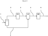
- the Applicant has implemented a new process which makes it possible to separately treat synthesis gas streams in specific sequences of steps and according to their composition and in particular from the point of view of CO 2 contents. and co. More particularly, the process of the invention incorporates in the process chain a fractionation step of the raw synthesis gas to be treated in at least two effluents, a first part and a complementary part, wherein said first part is subjected to a step of converting carbon monoxide to steam; and said complementary part is subjected to a step of catalytic hydrolysis of COS and HCN; the two resulting gas streams are then each separately treated in two dedicated acid gas removal steps, such as CO 2 and H 2 S, by washing with aqueous solutions of amines, before a recombination step of the two treated effluents.
- two dedicated acid gas removal steps such as CO 2 and H 2 S
- the process according to the invention makes it possible to significantly reduce the degradation of solvents composed of aqueous solutions of amines, to reduce the rate of solvent replacement, to improve the performance and operability of the process while reducing the flow of solvents. solvents necessary for the elimination of acid gases.
- the method according to the invention is economically more interesting by also allowing significant gains on investment and operating expenses.
- the purified synthesis gas thus obtained comprises less than 5% by volume of carbon dioxide CO 2 , preferably less than 2% by volume of CO 2 , and less than 50 ppm by H 2 S, preferably less than 10 ppm by H 2.
- S preferably less than 5 ppmv of H 2 S, very preferably less than 1 ppmv of H 2 S and also residual amounts of COS and HCN, and preferably less than 20 ppmv of COS, preferably less 10 ppmv of COS, very preferably less than 5 ppmv of COS, and even more preferably less than 2 ppmv of COS, and less than 10 ppmv of HCN, preferably less than 5 ppmv of HCN, more preferably less than 1 ppmv of HCN.
- the synthesis gas from step d) of recombination contains H 2 and CO, and advantageously has a H 2 / CO molar ratio of preferably between 0.5 and 4, preferably between 1 and 3, more preferably between 1.5 and 2.5
- An advantage of the present invention lies in the fact of separately treating synthesis gas streams in specific sequences of steps and as a function of their composition difference, in particular their difference in CO and CO 2 contents.
- An advantage of the present invention is that it makes it possible to significantly reduce the degradation of the aqueous amine solutions used in the acid gas removal steps, in particular by minimizing the contact between CO and primary and secondary amines, and by greatly reducing the rate of formation of degradation products such as, for example, formamides and temperature-stable amine salts.
- An advantage of the present invention is to provide a method with improved performance and operability, because among other things to reduce the rate of replacement of solvents.
- An advantage of the present invention is to provide a cost-effective method through the separate treatment of synthesis gas streams for more efficient and effective removal of H 2 S, COS and HCN, and thus overall reduction of the necessary amine fluxes, a reduction in the size of the treatment units, and thus a gain on investment and operating expenses.
- the process according to the present invention allows the elimination of a large quantity of impurities such as H 2 S, COS, CO 2 , HCN, NH 3 and the metals possibly present in the synthesis gas.
- the synthesis gas treated in the process of the invention can advantageously be obtained by the transformation of natural gas, coal or biomass, by processes such as steam reforming, autothermal reforming, or partial oxidation, or by the decomposition of methanol, or from any other method known to those skilled in the art.
- the synthesis gas can also be obtained from a feedstock comprising at least one biomass fraction and optionally at least a fraction of another feedstock.
- Biomass is understood to mean any type of biomass, preferably solid-type biomass, and in particular lignocellulosic biomass. Examples of non-limiting types of biomass include, for example, farm residues (including straw, corn cobs), logging residues, logging products, sawmill residues, crops dedicated to example coppice with short rotation.
- the synthesis gas may also be produced from a feedstock further comprising at least a fraction of another feedstock, preferably at least one gaseous, solid and / or liquid hydrocarbon feed fraction ("co-processing" according to the Anglo-Saxon terminology).
- Said hydrocarbon feed fraction is understood in the context of the present invention as being a load fraction that may advantageously contain at least coal, petroleum coke (petcoke according to the English terminology), natural gas, petroleum residues, crude oils, crude heading oils, deasphalted oils, deasphalting asphalts, derivatives of petroleum conversion processes (for example: FCC HCO / Slurry, heavy GO / VGO coking, visbreaking residue or thermal process similar, etc.), tar sands or their derivatives, shale gas and oil shale or their derivatives, liquid biomass (eg rapeseed oil, palm oil, pyrolysis oil, etc.), slurry biomass according to the Anglo-Saxon terminology corresponding to a mixture of liquid biomass with a solid hydrocarbon feedstock
- the feedstock of the process according to the invention may therefore be a feedstock comprising at least one solid biomass fraction, and optionally at least one fraction of another gaseous feedstock, solid or liquid, alone or as a mixture.
- the composition of the raw synthesis gas is a function of the feedstock and the process used for the preparation of the gas.
- the raw synthesis gas generally contains carbon monoxide CO, hydrogen H 2 , carbon dioxide CO 2 , and water.
- the synthesis gas contains between 5 and 65% by volume of CO, preferably between 10 and 50% by volume of CO, preferably between 12 and 45% by volume of CO, and between 1 and 65% by volume of H 2 , preferably between 3 and 50% by volume of H 2 , preferably between 5 and 35% by volume of H 2 , and between 1 and 50% by volume of CO 2 , preferably between 5 and 45% by volume of CO 2 , preferably between 10 and 40% CO 2 volume.
- a synthesis gas contains many impurities such as sulfur compounds (such as H 2 S, COS, mercaptans), nitrogen compounds (such as NH 3 , HCN), halogenated compounds (HF, HCl, HBr, HI), and also metals, such as, for example, mercury, selenium and metal carbonyls.
- impurities such as sulfur compounds (such as H 2 S, COS, mercaptans), nitrogen compounds (such as NH 3 , HCN), halogenated compounds (HF, HCl, HBr, HI), and also metals, such as, for example, mercury, selenium and metal carbonyls.
- the levels of impurities in the raw synthesis gas are a function of the feedstock and the process used for the preparation of the gas. More particularly, the contents of sulfur compounds can be between 20 and 20000 ppmv, or even 50 to 15000 ppmv. The contents of nitrogen compounds can be between 20 and 20000 ppmv, or even 50 to 15000 ppmv.
- the respective proportions of said flows resulting from the division step a) are advantageously determined in order to obtain a recombined effluent, which, after any purification steps intended to eliminate the residual impurities, feeds the Fischer-Tropsch synthesis step, and has a molar ratio H 2 / CO preferably between 0.5 and 4, preferably between 1 and 3, more preferably between 1.5 and 2.5.
- the first stream represents at least 20 to 80% by volume, preferably 30 to 70% by volume, preferably 40 to 60% by volume of the stream of synthesis gas entering in said stage a).
- Step b1) converting carbon monoxide to steam
- Said step b1) makes it possible to produce a gaseous effluent rich in H 2 and depleted in carbon monoxide CO. This reaction, however, produces significant amounts of CO 2 .
- the production step of the synthesis gas generally leads to a production of hydrogen and carbon monoxide in a molar ratio H 2 / CO not optimal for the Fischer-Tropsch reaction, particularly when the catalyst used is a catalyst based on cobalt which advantageously requires an optimum H 2 / CO molar ratio of about 2 to direct the synthesis towards the production of middle distillates.
- step b1) is carried out at an inlet temperature of between 150 and 280 ° C, preferably between 200 and 280 ° C.
- the reaction step b1) of conversion of carbon monoxide with steam is carried out at an absolute pressure of between 20 and 120 bar, preferably between 25 and 60 bar, and more preferably between 30 and 50 bar; at a volume hourly velocity VVH (charge volume / catalyst volume / hour) of between 1000 and 10000 h -1 , preferably between 1000 and 9000 h -1 and more preferably between 1500 and 8500 h -1 ; at a temperature between 150 and 550 ° C, preferably between 200 and 550 ° C, and more preferably between 250 and 500 ° C.
- VVH charge volume / catalyst volume / hour
- the catalyst used in this step b1) is a catalyst comprising at least one element of group VIII and / or at least one element of group VIB of the Mendeleev periodic classification (group VIII corresponds to group 8, 9 and 10, and Group VIB in Group 6 according to the new notation of the Periodic Table of Elements: Handbook of Chemistry and Physics, 81st Edition, 2000-2001 ).
- the catalyst is a catalyst comprising cobalt sulphide and / or molybdenum sulphide.
- the catalyst support is usually a porous solid selected from the group consisting of aluminas, silica and silica aluminas.
- the catalyst support is alumina.
- the catalyst used can be promoted with an alkaline or alkaline earth promoter. The conversion reaction of carbon monoxide makes it possible to considerably increase the hydrogen content in the outgoing effluent.
- step b1) is carried out with a H 2 O / CO ratio of between 0.5 and 100, preferably between 0.5 and 25, more preferably between 1.5 and 10. Because the exothermic character of the conversion reaction of carbon monoxide to steam, the gaseous effluent from this step has a temperature between 250 and 550 ° C.
- the catalyst used during the step of converting carbon monoxide to steam b1) also makes it possible to promote the hydrolysis reactions of carbon oxysulfide (COS) and hydrogen cyanide (HCN) in H 2 S and NH 3 .
- This step allows the partial elimination of COS and HCN which are poisons for the Fischer-Tropsch synthesis catalyst.
- the hydrolysis of COS and HCN during the step of conversion of carbon monoxide to vapor b1) allows further elimination of COS and HCN, when combined with the elimination stage. acid gas b2) downstream.
- the solvent used in the downstream stage b2) is also protected from a degradation of the reactive amines, which, if necessary, could be caused by the presence of HCN.
- step b1) makes it possible to obtain a gaseous effluent comprising at least hydrogen H 2 and carbon dioxide CO 2 .
- Said effluent advantageously contains between 5 and 95% by volume of H 2 , preferably between 10 and 80% by volume of H 2 , preferably between 20 and 60% by volume of H 2 , and contains between 5 and 60% by volume of carbon dioxide CO 2 , preferably between 10 and 50% by volume of CO 2 , preferably between 15 and 45% by volume of CO 2 .
- Said effluent also advantageously contains less than 15% by volume of carbon monoxide CO, preferably less than 10% by volume of CO, more preferably less than 5% by volume of CO, even more preferably less than 3% by volume of CO. .
- the effluent leaving step b1) for converting carbon monoxide to steam also contains less than 100 ppmv of COS, preferably less than 80 ppmv of COS, and more preferably less than 60 ppmv. of COS, and less than 10 ppmv of HCN, preferably less than 5 ppmv of HCN, and more preferably less than 2 ppmv of HCN.
- the gaseous effluent resulting from step b1) of conversion of carbon monoxide to steam is sent to a step of catalytic hydrolysis of the COS and HCN in H 2 S and NH 3 (step b1 '), preferably after cooling to a temperature between 100 and 400 ° C, preferably between 200 and 350 ° C.
- Step b1 ') is then carried out according to the same operating conditions as those of the catalytic hydrolysis step c1) described below.
- the effluent at the outlet of the hydrolysis unit of step b1 ') contains less than 50 ppmv of COS, preferably less than 25 ppmv of COS, and more preferably less than 10 ppmv of COS. , and less than 5 ppmv of HCN, preferably less than 1 ppmv of HCN, and more preferably less than 0.5 ppmv of HCN.
- the catalytic hydrolysis step b1 ') of the COS and HCN compounds present in the first synthesis gas stream resulting from step b1) may advantageously be implemented in step b2). removing acid gases from said first stream of synthesis gas.
- This embodiment is described in the patent FR 2950265 .
- the effluent from step b1) is washed with water.
- This water washing step has the advantage of eliminating impurities such as NH 3 and HCl which are soluble in water and which are particularly harmful to the operation of step b2) of eliminating acid gases.
- a step of removing acid gases from the gaseous effluent resulting from step b1) of conversion of carbon monoxide to steam and having optionally undergone step b1 ') of catalytic hydrolysis of COS and HCN is carried out by placing said effluent in contact with an aqueous solution of amines comprising at least one primary and / or secondary amine, mixed with or not with at least one sterically hindered tertiary or secondary amine.
- Acidic gases are understood to mean sulfur compounds H 2 S and COS, and the CO 2 remaining in the gaseous effluent from step b1).
- the composition of the gaseous effluent from step b1), enriched in H 2 and CO 2 and depleted in carbon monoxide CO, allows the use in said step b2) of a suitable aqueous solution of amines.
- a suitable aqueous solution of amines ensuring a high CO 2 and COS removal thanks to rapid reaction kinetics but sensitive to the presence of CO can be used.
- solvents consist of aqueous solutions of primary and / or secondary amines, optionally mixed with a tertiary amine or a sterically hindered secondary amine.
- tertiary amine means any molecule having one or more amine functions and all of whose amine functions are tertiary.
- hindered secondary amine any molecule having one or more amine functions and whose amine functions are tertiary or secondary cluttered, at least one being secondary and characterized by a steric hindrance.
- bulk of the secondary amine function is meant either the presence of at least one quaternary carbon ⁇ (alpha) nitrogen, or the presence of two tertiary carbons ⁇ and ⁇ 'position.
- the positions a and ⁇ 'of the nitrogen of a secondary amine are defined as in the following representation:
- the primary amine (s) are chosen from monoethanolamine, aminoethylethanolamine, diglycolamine, 2-amino-2-methyl-1-propanol and its non-N-substituted derivatives, alone or as a mixture.
- the secondary amine (s) are chosen from diethanolamine (DEA), diisopropanolamine, piperazine and its derivatives in which at least one nitrogen atom is not substituted, morpholine and its non-N substituted derivatives, piperidine and its non-N-substituted derivatives, N- (2'-hydroxyethyl) -2-amino-2-methyl-1-propanol, N- (2'-hydroxypropyl) -2-amino-2-methyl-1- propanol, N- (2'-hydroxybutyl) -2-amino-2-methyl-1-propanol, alone or in admixture.
- DEA diethanolamine
- diisopropanolamine piperazine and its derivatives in which at least one nitrogen atom is not substituted
- morpholine and its non-N substituted derivatives piperidine and its non-N-substituted derivatives
- step b2) operates in the presence of an aqueous solution of amines comprising at least one primary and / or secondary amine, mixed with at least one tertiary amine or a hindered secondary amine
- the primary amine (s) and / or secondary are called "activators”.
- This type of formulation makes it possible to optimize the absorption capacities of acid gases as well as the absorption kinetics of CO 2 and COS.
- the absorption kinetics of CO 2 and COS being maximized by the use of a primary amine or a secondary amine, the removal of acid gases from the gaseous effluent will be particularly favored.
- the tertiary amine or amines are chosen from methyldiethanolamine (MDEA), triethanolamine, ethyldiethanolamine, diethylethanolamine, dimethylethanolamine, 1-methyl-4- (3-dimethylaminopropyl) -piperazine, 1-ethyl- 4- (diethylaminoethyl) piperazine, 1-methyl-4-hydroxy-piperidine, 1-methyl-2-hydroxymethyl-piperidine, tert-butyldiethanolamine, 1,2-bis (2-dimethylaminoethoxy) ethane, bis (dimethylamino-3-propyl) ether, bis (diethylamino-3-propyl) ether, (dimethylamino-2-ethyl) - (dimethylamino-3-propyl) -ether, (dimethylamino-2-ethyl) - (dimethylamino-3-propyl) -ether, (dimethyla
- the hindered secondary amine (s) are chosen from N- (2'-hydroxyethyl) -2-amino-2-methyl-1-propanol, N- (2'-hydroxypropyl) -2-amino-2- methyl-1-propanol, N- (2'-hydroxybutyl) -2-amino-2-methyl-1-propanol.
- the aqueous amine solution comprises between 10% and 90% by weight of a primary amine, preferably between 20% and 60% by weight, very preferably between 25% by weight. and 50% mass; the solution comprises between 10% and 90% by weight of water, preferably between 40% and 80% by weight of water, very preferably from 50% to 75% by weight of water.
- the aqueous amine solution comprises between 10% and 90% by weight of a secondary amine, preferably between 20% and 60% by weight, very preferably between 25% and 50% by weight; the solution comprises between 10% and 90% by weight of water, preferably between 40% and 80% by weight of water, very preferably from 50% to 75% by weight of water.
- the aqueous solution of amines comprises between 10% and 90% by weight of a tertiary amine, preferably between 20% and 60% by weight, very preferably between 25% and 50% by weight; the solution comprises between 10% and 90% by weight of water, preferably between 40% and 80% by weight of water, very preferably from 50% to 75% by weight of water; and the solution comprises from 0.5% to 30% by weight of said activator, preferably from 0.5% to 15% by weight, very preferably from 0.5% to 10% by weight.
- the aqueous amine solution comprises between 10% and 90% by weight of a hindered secondary amine, preferably between 20% and 60% by weight, very preferably between 25% and 50% by weight; the solution comprises between 10% and 90% by weight of water, preferably between 40% and 80% by weight of water, very preferably from 50% to 75% by weight of water; and the solution comprises from 0.5% to 30% by weight of said activator, preferably from 0.5% to 15% by weight, very preferably from 0.5% to 10% by weight.
- the acid gas removal step b2) comprises a first step of absorption of the acidic compounds of the synthesis gas to be treated by contacting this gas with the solvent in an absorber operating at the pressure of the gas to be treated, followed by a solvent regeneration step, generally operating at a pressure slightly above atmospheric pressure.
- Said acid gas extraction step may advantageously be carried out in an acid gas absorption column.
- the absorption column may advantageously be equipped with any type of internal promoting gas / liquid contact known to those skilled in the art such as trays, bulk packings, structured packings, the solvent being distributed at the top of said column and the gas flowing countercurrently therein.
- Said step of regeneration of the solvent can advantageously be implemented in order to reduce the solvent consumption in the unit which can thus be regenerated, and is generally carried out in a column equipped at the bottom of a reboiler and at the head of a condenser for cooling the acidic compounds released by the regeneration.
- This heat regeneration step generally operates at a pressure slightly above atmospheric pressure, generally between 1 and 5 bar, preferably between 1.5 and 3 bar.
- the temperature at the bottom of the column is generally between 100 and 160 ° C., more preferably between 100 and 140 ° C.
- the regeneration column may advantageously be equipped with any type of internal promoting gas / liquid contact known to those skilled in the art such as trays, bulk packings, structured packings.
- This regeneration step may advantageously be carried out in two stages in order to eliminate, on the one hand, a gas stream rich in CO 2 and, on the other hand, a gas stream rich in H 2 S.
- this regeneration step may advantageously comprise a step of partial regeneration of the solvent by expansion at an absolute pressure slightly greater than atmospheric pressure, generally between 1 and 10 bar, preferably between 1 and 5 bar, the solvent partially regenerated can be reintroduced into the absorption column at an intermediate level between the head and the bottom of the column.
- the absorption step of the acidic gases is advantageously carried out at an absolute pressure of between 20 and 120 bar, preferably between 25 and 60 bar, and even more preferably between 30 and 50 bar.
- the absorption step of the acidic gases is advantageously carried out at a temperature of between 20 and 100 ° C., preferably between 30 and 80 ° C.
- Step b1) makes it possible to obtain a gaseous effluent from the gaseous effluent depleted in H 2 S and CO 2 .
- said gaseous effluent comprises less than 5% by volume of carbon dioxide CO 2 , preferably less than 1% by volume of CO 2 , and less than 50 ppm by H 2 S, preferably less than 10 ppm by H 2 S preferably less than 5 ppmv of H 2 S, preferably less than 1 ppmv of H 2 S.
- Said gaseous effluent from said step b2) also advantageously contains less than 20 ppmv of COS, preferably less than 10 ppmv of COS, preferably less than 5 ppmv of COS, preferably less than 2 ppmv of COS, and less than 10 ppmv of COS.
- ppmv of HCN preferably less than 5 ppmv of HCN, preferably less than 1 ppmv of HCN.
- the complementary part resulting from step a) is subjected to a step of catalytic hydrolysis of COS and HCN in H 2 S and NH 3 (step c1).
- This step allows the partial elimination of COS and HCN which are poisons for the Fischer-Tropsch synthesis catalyst.
- the implementation of the catalytic hydrolysis step c1) allows further elimination of COS and HCN, when combined with the acid gas removal step c2) downstream.
- performing the hydrolysis of the HCN during this step, the solvent used in step c2) is also protected from a degradation of the reactive amines, which if necessary could be caused by the presence of HCN.
- the catalytic hydrolysis step c1) of carbon oxysulfide (COS) and of hydrogen cyanide (HCN) is, according to the invention, advantageously carried out in the presence of a catalyst containing a platinum-based compound, or an oxide of a member selected from the group consisting of titanium, zirconium, aluminum, chromium, zinc, or a mixture thereof.
- the hydrolysis catalyst is a catalyst based on titanium oxide.
- the catalyst used may also contain at least alkali metals, alkaline earth metals and / or rare earths, for example from precursors such as potassium hydroxide, sodium hydroxide, sodium carbonate or barium carbonate, sodium bicarbonate or barium carbonate. , calcium sulphate, sodium or barium acetate, sodium oxalate or barium.
- the hydrolysis step is advantageously carried out at a temperature of between 100 and 400 ° C., preferably between 200 and 350 ° C.
- step c1) of catalytic hydrolysis of COS and HCN is carried out at an absolute pressure of between 20 and 120 bar, preferably between 25 and 60 bar, and more preferably between 30 and 50 bar.
- the synthesis gas leaving the hydrolysis unit of step c1) advantageously contains between 5 and 65% CO 2, preferably between 10 and 50% CO, preferably between 12 and 45% by volume. CO, and between 1 and 65% volume of H 2 , preferably between 3 and 50% by volume of H 2 , preferably between 5 and 35% by volume of H 2 , and between 1 and 50% by volume of CO 2 , preferably between 5 and 45% CO 2 volume, preferably between 10 and 40% CO 2 volume.
- Said gaseous effluent at the outlet of the hydrolysis unit of step c1) also advantageously contains less than 25 ppmv of COS, preferably less than 10 ppmv of COS, and more preferably less than 5 ppmv of COS, and less than 5 ppmv of HCN, preferably less than 1 ppmv of HCN, and more preferably less than 0.5 ppmv of HCN.
- step c1) of catalytic hydrolysis of the COS and HCN compounds present in the second stream of synthesis gas resulting from step a) can advantageously be carried out in the elimination step c2) acid gases of said second stream of synthesis gas.
- This embodiment is described in the patent FR 2950265 .
- the effluent from step c1) is washed with water.
- This water washing step has the advantage of eliminating impurities such as water-soluble NH 3 and HCl and particularly harmful to the operation of the acid gas removal step c 2).
- the second stream of synthesis gas from step c1) and richer in CO undergoes a step of elimination of the acid gases by contacting said stream with an aqueous solution of amines comprising at least one tertiary amine.
- Said step c2) makes it possible to produce a gaseous effluent depleted of H 2 S and CO 2 .
- said gaseous effluent from step c2) comprises less than 10% volume of CO 2 , preferably less than 7% volume of CO 2 , and less than 50 ppmv of H 2 S, preferably less than 10 ppmv. H 2 S, preferably less than 5 ppmv H 2 S, preferably less than 1 ppmv H 2 S.
- Said gaseous effluent from said step c2) also advantageously contains less than 20 ppmv of COS, preferably less than 10 ppmv of COS, preferably less than 5 ppmv of COS, preferably less than 2 ppmv of COS, and less than 10 ppmv preferably less than 5 ppmv of HCN, preferably less than 1 ppmv of HCN.
- composition of the second stream of synthesis gas from step c1), rich in CO requires the use in said step c2) of an aqueous solution of suitable amines.
- an aqueous solution of amines with little or no sensitivity to the presence of CO must be used.
- an aqueous solution of tertiary amines not allowing direct reaction with CO will be preferred.
- the tertiary amine or amines are chosen from methyldiethanolamine (MDEA), triethanolamine, ethyldiethanolamine, diethylethanolamine, dimethylethanolamine, 1-methyl-4- (3-dimethylaminopropyl) -piperazine, 1-ethyl- 4- (diethylaminoethyl) piperazine, 1-methyl-4-hydroxy-piperidine, 1-methyl-2-hydroxymethyl-piperidine, tert-butyldiethanolamine, 1,2-bis (2-dimethylaminoethoxy) ethane, bis (dimethylamino-3-propyl) ether, bis (diethylamino-3-propyl) ether,
- MDEA methyldiethanolamine
- triethanolamine ethyldiethanolamine
- diethylethanolamine diethylethanolamine
- dimethylethanolamine 1-methyl-4- (3-dimethylaminopropyl) -piperazine
- the aqueous solution of amines comprises between 10% and 90% by weight of a tertiary amine, preferably between 20% and 60% by weight, very preferably between 25% and 50% by weight; the solution comprises between 10% and 90% by weight of water, preferably between 40% and 80% by weight of water, very preferably from 50% to 75% by weight of water.
- the acid gas elimination step c2) comprises a first step of absorption of the acidic compounds of the synthesis gas to be treated by contacting this gas with the solvent in an absorber operating at the pressure of the gas to be treated, followed by a solvent regeneration step, generally operating at a pressure slightly above atmospheric pressure.
- Said acid gas extraction step may advantageously be carried out in an acid gas absorption column.
- the absorption column may advantageously be equipped with any type of internal promoting gas / liquid contact known to those skilled in the art such as trays, bulk packings, structured packings, the solvent being distributed at the top of said column and the gas flowing countercurrently therein.
- Said step of regeneration of the solvent can advantageously be implemented in order to reduce the solvent consumption in the unit which can thus be regenerated, and is generally carried out in a column equipped at the bottom of a reboiler and at the head of a condenser for cooling the acidic compounds released by the regeneration.
- This thermal regeneration step generally operates at a pressure slightly above atmospheric pressure, generally between 1 and 5 bar, preferably between 1.5 and 3 bar.
- the temperature at the bottom of the column is generally between 100 and 160 ° C., more preferably between 100 and 140 ° C.
- the column regeneration can advantageously be equipped with any type of internal promoting gas / liquid contact known to those skilled in the art such as trays, loose packings, structured packings.
- This regeneration step may advantageously be carried out in two stages in order to eliminate, on the one hand, a gas stream rich in CO 2 and, on the other hand, a gas stream rich in H 2 S.
- this regeneration step may advantageously comprise a step of partial regeneration of the solvent by expansion at an absolute pressure slightly greater than atmospheric pressure, generally between 1 and 10 bar, preferably between 1 and 5 bar, the solvent partially regenerated can be reintroduced into the absorption column at an intermediate level between the head and the bottom of the column.
- the absorption step of the acidic gases is advantageously carried out at an absolute pressure of between 20 and 120 bar, preferably between 25 and 60 bar, and even more preferably between 30 and 50 bar.
- the absorption step of the acidic gases is advantageously carried out at a temperature of between 20 and 100 ° C., preferably between 30 and 80 ° C.
- the aqueous solution of amines used in the absorption step may already be partially charged with acid gases, if it comes in particular from the absorption step of a gas enrichment unit. acid or a Claus tail gas treatment unit.
- the regeneration step may advantageously be combined with a regeneration step of an acid gas enrichment unit or a Claus tail gas treatment unit.
- At least a portion and preferably all the gaseous effluents from steps b2) and c2) are recombined to obtain a purified synthesis gas.
- the purified synthesis gas from step d) of recombination comprises less than 5% volume of carbon dioxide CO 2 , preferably less than 2% volume of CO 2 .
- the purified synthesis gas from step d) of recombination contains less than 50 ppmv of H 2 S, preferably less than 10 ppmv of H 2 S, preferably less than 5 ppmv of H 2 S, preferably less than 1 ppmv of H 2 S, and also includes residual amounts of COS and HCN, ie less than 20 ppmv of COS, preferably less than 10 ppmv of COS, preferably less than 5 ppmv. ppmv of COS, preferably less than 2 ppmv of COS, and less than 10 ppmv of HCN, preferably less than 5 ppmv of HCN, preferably less than 1 ppmv of HCN.
- the synthesis gas from step d) of recombination contains H 2 and CO, and advantageously has a H 2 / CO molar ratio of preferably between 0.5 and 4, preferably between 1 and 3, more preferably between 1.5 and 2.5.
- the purified synthesis gas from step d) of recombination may still contain impurities that it may agree to eliminate according to the specifications of downstream processes.
- the synthesis gas from step d) contains less than 50 ppmv of H 2 S, preferably less than 10 ppmv of H 2 S, more preferably less than 5 ppmv of H 2 S, very preferably preferred less than 1 ppmv H 2 S, and also includes residual amounts of COS and HCN, preferably less than 20 ppmv COS, preferably less than 10 ppmv COS, most preferably less than 5 ppmv COS more preferably less than 2 ppmv of COS, and less than 10 ppmv of HCN, preferably less than 5 ppmv of HCN, preferably less than 1 ppmv of HCN.
- the purified synthesis gas may also contain less than 20 ppmv of NH 3 , preferably less than 10 ppmv of NH 3 , preferably less than 5 ppmv of NH 3 , very preferably less than 2 ppmv of NH 3. ., as well as heavy metals such as lead, arsenic and mercury.
- said purified synthesis gas may optionally undergo a final purification stage e) by passing through at least one guard bed and / or in a catalytic reactor. Said step completely eliminates the last traces of impurities remaining in the purified synthesis gas such as halogenated compounds, H 2 S, COS, HCN and NH 3 , and heavy metals such as lead, arsenic, mercury.
- the gaseous effluent from step e) is washed with water.
- This water washing step has the advantage of eliminating impurities such as NH 3 and HCl which are soluble in water and which are particularly harmful in the Fischer-Tropsch synthesis step.
- the final purification step e) is carried out at an absolute pressure of between 20 and 120 bar, preferably between 25 and 60 bar, and more preferably between 30 and 50 bar.
- the synthesis gas contains at the end of the final purification step, a total sulfur content of less than 10 ppbv, preferably less than 5 ppbv, more preferably less than 2 ppbv, and a lower HCN content of 10 ppbv, preferably less than 5 ppbv, more preferably less than 2 ppbv, and a lower NH 3 content of 1 ppmv, preferably less than 0.5 ppmv, more preferably less than 0.1 ppmv.
- the process according to the invention can be used for conditioning and purification of the gases used in the chemical synthesis units, such as, for example, the synthesis of methanol.
- the synthesis gases are generally used at a pressure of between 10 and 150 bar, preferably of 50 to 100 bar, and at a temperature of between 150 and 300 ° C., preferably between 220 and 300 ° C. and 280 ° C.
- the process according to the invention can be used for conditioning and purification of the gases used in cogeneration installations.
- the synthesis gases are generally used at a pressure of between 1 and 150 bar, preferably of 15 to 50 bar, and at a temperature of between 100 and 450.degree. C., preferably between 170 and 450.degree. 350 ° C.
- the synthesis gas resulting from the purification process according to the invention is sent to a Fischer-Tropsch synthesis step f).
- the Fischer-Tropsch synthesis step f) of the process is carried out from a feed comprising the effluent from step e) and allowing the production of a stream comprising hydrocarbons. synthetic liquids and at least one gaseous effluent.
- the feed of the Fischer-Tropsch synthesis step f) comprises carbon monoxide and hydrogen with a molar ratio H 2 / CO of between 0.5 and 4, preferably between 1 and 3. more preferably between 1.5 and 2.5.
- Fischer-Tropsch synthesis step f) is carried out in a reaction unit comprising one or more suitable reactors, the technology of which is known to those skilled in the art. It may be For example, multitubular fixed bed reactors, or bubble column type reactors, known in English as “slurry bubble columns", or microchannel reactors.
- step f) uses one or more bubble column type reactors. Since the synthesis is highly exothermic, this embodiment makes it possible, among other things, to improve the thermal control of the reactor and to create little loss of charge.
- the catalyst used in this step f) of Fischer-Tropsch synthesis is generally any solid catalytic known to those skilled in the art for performing the Fischer-Tropsch synthesis.
- the catalyst used in said step comprises cobalt or iron, more preferably cobalt.
- the catalyst used in step f) is generally a supported catalyst.
- the support may be, for example, based on alumina, silica or titanium.
- the temperature and pressure conditions are variable and adapted to the catalyst used in this step f).
- the absolute pressure is generally between 10 and 60 bar, preferably between 15 and 35 bar and preferably between 20 and 30 bar.
- the temperature may generally be between 170 and 280 ° C., preferably between 190 and 260 ° C. and preferably between 210 and 240 ° C.
- FIGS. figures 1 , 2 and 3 These embodiments are given by way of example and are not limiting in nature. This illustration of the method of the invention does not include all the components necessary for its implementation. Only the elements necessary for understanding the invention are represented therein, those skilled in the art being able to complete this representation to implement the invention.
- step a) corresponds to a step of fractionation of synthesis gas No. 1 into two gas flows of identical composition No. 2 and No. 4, the flow of gas No. 2 being sent to a step b1) converting the CO monoxide to the steam to give a flow of gas No. 3, the gas streams No. 3 and No. 4 being recombined during the recombination step d) to give the gas flow No. 5, the flow of gas No. 5 then undergoing a step b2) of removing the acid gases to give a gas stream No. 6.
- Table 1 The evolution of the composition of the gas is specified in Table 1 below: The numbers of the flows refer to the figure 4 .
- Table 1 Composition of the synthesis gas to be purified. Flow n ° 1, n ° 2, n ° 4 Stream 3 Stream 5 Flow n ° 6 H 2 (% volume) 14.6 39.6 27.4 63.4 CO (% volume) 25.7 2.0 13.6 31.5 CO 2 (% volume) 6.6 31.5 19.4 0,001 H 2 O (% volume) 50.8 24.6 37.4 0.25 H 2 S (ppmvl) 4300 4750 4530 1 COS (ppmv) 480 30 250 145 HCN (ppmv) 200 1 100 15 NH 3 (ppmv) 650 850 750 10 H 2 / CO 0.6 19.8 2.0 2.0
- the figure 1 describes a sequence of processes according to the invention.
- the catalyst Cat2 used is an industrial catalyst based on titanium oxide. This industrial catalyst has a titanium oxide content of 85% by weight. Its specific surface area determined by the BET method is 120 m 2 / g. The catalyst is in the form of extrudates approximately 3 mm in diameter.
- the purification scheme according to the invention requires a flow rate of 200 m 3 / h of MDEA in step c2) and a flow rate of 1340 m 3 / h.
- MDEA h activated in step b2).
- the method according to the invention therefore makes it possible to reduce the overall flow rate of solvent used by 6%.
- the energy consumptions necessary for the regeneration of the aqueous solutions of amines are also diminished in the same proportions.
- the residual contents of acidic compounds in the gas at the end of the washing step are: for the H 2 S of 1 ppmv, for the COS of 10 ppmv, and for the HCN of 1 ppmv, either of the contents in impurities well below those obtained in Example 1 according to the prior art.
- the synthesis gas obtained has a ratio H 2 / CO equal to 2.
- the figure 2 describes a sequence of processes according to the invention.
- Table 4 refers to the figure 2 .
- Table 4 Composition of the synthesis gas to be purified.
- Solvent flow stage b2 Solvent flow stage b
- the purification scheme according to the invention requires a flow rate of 200 m 3 / h of MDEA in step c2) and a flow rate of 1340 m 3 / h.
- MDEA h activated in step b2).
- the method according to the invention therefore makes it possible to reduce the overall flow rate of solvent used by 6%.
- the energy consumptions necessary for the regeneration of the aqueous solutions of amines are also diminished in the same proportions.
- the residual contents of acid compounds in the gas at the end of the washing step are: for H 2 S of 1 ppmv, for the COS of 4 ppmv, and for HCN 1 ppmv, ie impurity levels well below those obtained in Example 1 according to the prior art.
- the synthesis gas obtained has a ratio H 2 / CO equal to 2.
- the test consists in comparing the stability of the amine in a mixture at 5 bar of CO or CO 2 at 140 ° C. for 14 days.
- the temperature is set at 140 ° C, corresponding to the temperature of the bottom of the regeneration column.
- the degradation results in the presence of CO 2 are taken as reference.
- Each test was repeated once ("test 1", "test 2").
- the table below presents the results of the tests carried out: Degradation 5 bar CO 2 C% m Trial 1 Trial 2 piperazine 7.7 26% 28% Degradation 5 bar CO piperazine 7.7 51% 53%
- piperazine secondary amine degrades about twice as much in the presence of CO than with CO 2 . This confirms that the use of piperazine as an activator, and more broadly the use of secondary amine is justified for the treatment of a gas depleted of CO during the washing step b2) downstream of the step conversion of CO to steam b1).
- the test consists in comparing the stability of each amine in a mixture at 5 bar of CO at 140 ° C. for 14 days.
- the temperature is set at 140 ° C, corresponding to the temperature of the bottom of the regeneration column. Samples taken over time and their assays by gas phase chromatography make it possible to follow the evolution of the concentrations over the duration of the test.
- step b2) the contact between CO and primary and / or secondary amines is minimized because of the composition of the gas to be treated having a reduced CO content relative to the raw synthesis gas .
- step c2) the tertiary amine (s) used are less sensitive to degradation by CO.
Description
La présente invention concerne le domaine de la purification des gaz de synthèse contenant du monoxyde de carbone CO, en général. Elle concerne plus particulièrement les procédés permettant d'éliminer les gaz acides tels que par exemple le CO2, l'H2S, le COS, et l'HCN en mettant en oeuvre un lavage par un ou plusieurs solvants.The present invention relates to the field of purification of synthesis gases containing carbon monoxide CO, in general. It relates more particularly to processes for removing acid gases such as for example CO 2 , H 2 S, COS, and HCN by carrying out a washing with one or more solvents.
De manière avantageuse, le procédé de l'invention est mis en oeuvre en amont d'une unité de synthèse Fischer-Tropsch, de façon à éliminer les impuretés et en particulier les gaz acides qui sont néfastes au bon fonctionnement de ladite unité. Il peut également être utilisé afin de purifier le gaz de synthèse mis en oeuvre par exemple, dans les installations de cogénération, dans les procédés de synthèse chimique tels que les procédés de synthèse du méthanol.Advantageously, the process of the invention is carried out upstream of a Fischer-Tropsch synthesis unit, so as to eliminate impurities and in particular acid gases which are detrimental to the proper functioning of said unit. It can also be used to purify the synthesis gas used, for example, in cogeneration plants, in chemical synthesis processes such as methanol synthesis processes.
Les gaz de synthèse sont généralement des mélanges gazeux comprenant du monoxyde de carbone CO, de l'hydrogène H2, de la vapeur d'eau et du dioxyde de carbone CO2. Ils peuvent être obtenus via la transformation du gaz naturel, du charbon, des résidus pétroliers et/ou de la biomasse par des procédés tels que le vaporeformage, le reformage autotherme, ou l'oxydation partielle, ou encore via la décomposition du méthanol, ou à partir de tout autre procédé connu de l'Homme du métier.The synthesis gases are generally gaseous mixtures comprising carbon monoxide CO, hydrogen H 2 , water vapor and carbon dioxide CO 2 . They can be obtained through the transformation of natural gas, coal, petroleum residues and / or biomass by processes such as steam reforming, autothermal reforming, or partial oxidation, or through the decomposition of methanol, or from any other method known to those skilled in the art.
Les gaz de synthèse contiennent des composés chimiques intermédiaires pouvant être valorisés dans une multitude d'application telles que les installations de cogénération, et/ou dans les procédés de synthèse chimique tels que les procédés de synthèse du méthanol, de l'hydrogène, de l'ammoniac, du méthane ou bien encore en oxo-chimie. Les gaz de synthèse sont également mis en oeuvre dans les procédés de production d'hydrocarbures de synthèse obtenus par exemple par la réaction Fischer-Tropsch. L'ensemble des fractions GPL (Gaz de Pétrole Liquéfié), naphta, essence, kérosène, et gazole et bases lubrifiantes ou produits de spécialités qui en découlent se caractérise par un haut niveau de performances techniques et environnementales.The synthesis gases contain intermediate chemical compounds which can be recovered in a multitude of applications such as cogeneration plants, and / or in chemical synthesis processes such as the processes for the synthesis of methanol, hydrogen ammonia, methane or even oxo-chemistry. The synthesis gases are also used in synthetic hydrocarbon production processes obtained for example by the Fischer-Tropsch reaction. All the fractions LPG (liquefied petroleum gas), naphtha, gasoline, kerosene, and diesel and lubricating bases or specialty products which result from it is characterized by a high level of technical and environmental performances.
Cependant, les gaz de synthèse bruts obtenus selon les procédés dont ils sont issus contiennent, en outre, un certain nombre d'impuretés parmi lesquelles des composés soufrés tels que le sulfure d'hydrogène H2S et le sulfure de carbonyle COS, des composés azotés tels que l'ammoniac NH3 et le cyanure d'hydrogène HCN, des composés halogénés, et des métaux qui sont généralement éliminés afin que le gaz n'en contienne plus qu'à des teneurs résiduelles, d'une part afin de ne pas altérer le bon fonctionnement des unités situées en aval et d'autre part de respecter les normes environnementales. Par ailleurs le dioxyde de carbone CO2, bien que considéré comme inerte dans le gaz de synthèse pour la plupart de ses applications, est cependant présent en grande quantité et doit également être éliminé pour atteindre des teneurs de l'ordre de quelques pourcents.However, the raw synthesis gases obtained according to the processes from which they are derived contain, in addition, a number of impurities including sulfur compounds such as hydrogen sulfide H 2 S and carbonyl sulphide COS, compounds such as NH 3 ammonia and HCN hydrogen cyanide, halogenated compounds, and metals which are generally removed to that the gas contains only residual levels, on the one hand so as not to affect the proper functioning of downstream units and on the other hand to meet environmental standards. Moreover, carbon dioxide CO 2 , although considered inert in synthesis gas for most of its applications, is nevertheless present in large quantities and must also be eliminated to reach contents of the order of a few percent.
Les impuretés présentes dans le gaz de synthèse non purifié peuvent entraîner une corrosion accélérée des installations dans lesquelles il est mis en oeuvre, telles que par exemple les turbines à gaz dans les unités de cogénération (ou "IGCC" pour "Integrated Gasification Combined Cycle" selon la terminologie anglo-saxonne), et sont susceptibles d'empoisonner les catalyseurs utilisés pour les procédés de synthèse chimique tels que ceux utilisés dans la synthèse Fischer-Tropsch ou du méthanol, ou encore d'atténuer les performances des matériaux utilisés dans les piles à combustibles. Des considérations environnementales imposent également l'élimination des impuretés présentes dans les gaz.
Dans le cas particulier de la synthèse Fischer-Tropsch, des spécifications sur le gaz de synthèse portent ainsi sur :
- les teneurs relatives en H2 et CO, pour lesquelles un ratio H2/CO est optimisé pour la synthèse d'hydrocarbures, et est généralement compris entre 1,5 et 2,5,
- la teneur en CO2, devant être au plus de 5% afin que le fonctionnement de l'unité Fischer-Tropsch soit optimal,
- les teneurs en impuretés parmi lesquelles les composés soufrés, azotés, halogénés, métalliques susceptibles d'empoisonner le catalyseur : les spécifications requises en entrée de l'unité Fischer-Tropsch sont particulièrement sévères, les teneurs présentes dans le gaz de synthèse devant être généralement inférieures à 10 ppb masse pour les impuretés soufrées, inférieure à 10 ppb masse pour l'HCN, inférieure à 10 ppb masse pour NH3, et inférieures à 10 ppb masse pour les impuretés halogénées [
M.J.A. Tijmensen, A.P.C. Faaij, C.N. Hamelinck, M.R.M. van Hardeveld, "Exploration of the possibilities for production of Fischer-Tropsch liquids and power via biomass gasification", Biomass and Bioenergy, 2002, 23(2), 129-152
In the particular case of the Fischer-Tropsch synthesis, specifications on the synthesis gas thus relate to:
- the relative contents of H 2 and CO, for which an H 2 / CO ratio is optimized for hydrocarbon synthesis, and is generally between 1.5 and 2.5,
- the CO 2 content must be at most 5% so that the operation of the Fischer-Tropsch unit is optimal,
- impurity contents, including sulfur, nitrogen, halogenated and metallic compounds capable of poisoning the catalyst: the specifications required for entry into the Fischer-Tropsch unit are particularly severe, since the contents present in the synthesis gas must be generally lower at 10 ppb mass for sulfur impurities, less than 10 ppb mass for HCN, less than 10 ppb mass for NH 3 , and less than 10 ppb mass for halogenated impurities [
MJA Tijmensen, APC Faaij, CN Hamelinck, MRM van Hardeveld, "Exploration of the possibilities for production of Fischer-Tropsch liquids and power via biomass gasification", Biomass and Bioenergy, 2002, 23 (2), 129-152
Le gaz de synthèse brut, issu directement de la gazéification ou obtenu selon tout autre moyen connu de l'Homme du métier, doit ainsi subir des étapes de conditionnement de gaz visant à atteindre les spécifications requises pour l'application dans laquelle il est mis en oeuvre.The raw synthesis gas, directly from the gasification or obtained by any other means known to those skilled in the art, must thus undergo gas conditioning steps to achieve the specifications required for the application in which it is implemented. artwork.
L'étape de production du gaz de synthèse mise en oeuvre conduit à une production d'hydrogène et de monoxyde de carbone dont les teneurs relatives dépendent des charges utilisées, du procédé, et des conditions opératoires de transformation [
Afin d'atteindre le rapport molaire H2/CO requis par la synthèse Fischer-Tropsch, le gaz de synthèse brut est généralement fractionné en deux flux, dont un est dirigé vers une section de conversion du monoxyde de carbone à la vapeur ("WGS" ou "Water Gas Shift" selon la terminologie anglo-saxonne) permettant de produire un flux gazeux riche en hydrogène et appauvri en monoxyde de carbone. Cette réaction produit cependant des quantités importantes de CO2. Les proportions respectives entre le flux de gaz subissant la réaction de conversion du monoxyde de carbone à la vapeur et ladite partie complémentaire sont généralement déterminées afin d'obtenir après recombinaison un effluent présentant le rapport molaire H2/CO requis pour le bon fonctionnement du procédé Fischer-Tropsch, c'est-à-dire autour de 2. Le gaz obtenu après recombinaison contient ainsi une teneur en CO2 plus importante par rapport au gaz de synthèse brut.In order to reach the H 2 / CO molar ratio required by Fischer-Tropsch synthesis, the raw synthesis gas is generally split into two streams, one of which is directed to a section of conversion of carbon monoxide to steam ("WGS "or" Water Gas Shift "according to the English terminology) for producing a gas stream rich in hydrogen and depleted in carbon monoxide. This reaction, however, produces significant amounts of CO 2 . The respective proportions between the flow of gas undergoing the reaction of carbon monoxide conversion with steam and said complementary part are generally determined in order to obtain after recombination an effluent having the molar ratio H 2 / CO required for the proper operation of the process Fischer-Tropsch, that is to say around 2. The gas obtained after recombination thus contains a higher CO 2 content relative to the crude synthesis gas.
L'élimination des gaz acides contenus dans le flux de gaz recombiné, et en particulier le CO2 et l'H2S est généralement conduite par lavage au solvant.
En particulier, la technique de lavage au solvant peut mettre en oeuvre des solutions aqueuses d'alcanolamines telles que la monoéthanolamine (MEA), la diéthanolamine (DEA), la diisopropanolamine (DIPA), la méthyldiéthanolamine (MDEA) ou la triéthanolamine (TEA) qui sont utilisées classiquement pour l'adoucissement du gaz naturel. Dans ce cas, les composés à éliminer (H2S, CO2) réagissent chimiquement avec le solvant [
In particular, the solvent washing technique can use aqueous solutions of alkanolamines such as monoethanolamine (MEA), diethanolamine (DEA), diisopropanolamine (DIPA), methyldiethanolamine (MDEA) or triethanolamine (TEA). which are conventionally used for the softening of natural gas. In this case, the compounds to be removed (H 2 S, CO 2 ) react chemically with the solvent [
Les teneurs en gaz acides dans le gaz de synthèse en aval de l'étape de lavage au solvant sont généralement au plus quelques ppmv de H2S (généralement moins de 10 ppmv), et au plus quelques pourcents de CO2 (généralement moins de 7% volume). En raison des teneurs élevées en CO2 contenues dans les gaz de synthèse bruts, des amines présentant des cinétiques d'absorption du CO2 rapides sont généralement envisagées, à savoir des amines primaires ou secondaires telle que la monoéthanolamine (MEA), la diéthanolamine (DEA), ou des amines tertiaires activées à l'aide d'une amine secondaire. Par exemple le document
Un des principaux inconvénients de ce type de schéma est la dégradation par le CO de l'amine secondaire utilisée comme un activateur de la cinétique d'absorption du CO2. En effet, le CO peut entraîner la formation de sels de type formiates d'amines, stables à haute température, et de formamides par réaction avec les amines primaires et secondaires, produits de dégradation des amines. Ces composés sont susceptibles de s'accumuler dans le solvant, provoquer une diminution de son efficacité, et dans certains cas entraîner une corrosion accélérée des installations en raison des propriétés chélatantes de certains produits de dégradation. La formation de ces produits de dégradation altère les performances des procédés de lavage par des solutions aqueuses d'amines, ainsi que leur opérabilité (augmentation du taux de remplacement du solvant, dans certains cas retraitement et/ou réactivation du solvant, augmentation de la fréquence d'arrêts des unités, ...) et a un impact négatif sur le coût du procédé (dépenses d'investissement et d'exploitation).One of the main drawbacks of this type of scheme is the degradation by CO of the secondary amine used as an activator of the CO 2 absorption kinetics. Indeed, CO can result in the formation of formate salts of amines, stable at high temperature, and formamides by reaction with primary amines and secondary amine degradation products. These compounds are likely to accumulate in the solvent, cause a decrease in its effectiveness, and in some cases lead to accelerated corrosion of the plants because of the chelating properties of certain degradation products. The formation of these degradation products alters the performance of washing processes by aqueous solutions of amines, as well as their operability (increase of the solvent replacement rate, in some cases reprocessing and / or reactivation of the solvent, increase of the frequency unit shutdowns, etc.) and has a negative impact on the cost of the process (investment and operating expenses).
Les amines tertiaires ne sont en revanche pas ou peu sensibles à la présence de CO, qui entraîne dans ce cas une dégradation réduite du solvant, mais présentent des cinétiques d'élimination de CO2 limitée par rapport aux amines activées. La mise en oeuvre d'amines tertiaires pour le traitement de gaz de synthèse contenant de forte quantité de CO2 nécessiterait des colonnes d'absorption de très grande hauteur.Tertiary amines, on the other hand, are not or only slightly sensitive to the presence of CO, which in this case causes reduced degradation of the solvent, but has limited CO 2 removal kinetics compared with activated amines. The use of tertiary amines for the treatment of synthesis gas containing a large amount of CO 2 would require very high absorption columns.
Par ailleurs, lors de l'utilisation de ces solvants, la teneur minimale en H2S qu'il est possible d'obtenir après traitement du gaz est de quelques ppmv, l'élimination du COS reste partielle, de l'ordre de 80% pour une élimination poussée. L'HCN est également éliminé, au détriment toutefois d'une dégradation irréversible du solvant [
Un objet de la présente invention est de proposer un procédé de conditionnement et de purification des gaz de synthèse amélioré permettant d'obtenir un gaz de synthèse compatible avec son utilisation dans les procédés de synthèse de composés hydrocarbonés tels que le procédé Fischer-Tropsch.An object of the present invention is to provide an improved synthesis gas purification and conditioning method for obtaining a synthesis gas compatible with its use in hydrocarbon synthesis processes such as the Fischer-Tropsch process.
Dans la présente invention, la demanderesse a mis en oeuvre un nouveau procédé qui permet de traiter séparément des flux de gaz de synthèse dans des enchainements spécifiques d'étapes et en fonction de leur composition et en particulier du point de vue des teneurs en CO2 et CO.
Plus particulièrement, le procédé de l'invention intègre dans la chaîne du procédé une étape de fractionnement du gaz de synthèse brut à traiter en au moins deux effluents, une première partie et une partie complémentaire, dans lequel ladite première partie est soumise à une étape de conversion du monoxyde de carbone à la vapeur; et ladite partie complémentaire est soumise à une étape d'hydrolyse catalytique du COS et de l'HCN ; les deux flux de gaz résultants sont ensuite chacun traités séparément lors de deux étapes dédiées d'élimination des gaz acides, tels que CO2 et H2S, par lavage à l'aide de solutions aqueuses d'amines, avant une étape de recombinaison des deux effluents traités.
Le procédé selon l'invention permet de réduire de manière significative la dégradation des solvants composés de solutions aqueuses d'amines, de diminuer le taux de remplacement des solvants, d'améliorer les performances et l'opérabilité du procédé tout en réduisant le flux de solvants nécessaire à l'élimination des gaz acides. En plus des avantages observés en termes de performances d'élimination des gaz acides, le procédé selon l'invention est économiquement plus intéressant en permettant également des gains significatifs sur les dépenses d'investissement et d'exploitation.In the present invention, the Applicant has implemented a new process which makes it possible to separately treat synthesis gas streams in specific sequences of steps and according to their composition and in particular from the point of view of CO 2 contents. and co.
More particularly, the process of the invention incorporates in the process chain a fractionation step of the raw synthesis gas to be treated in at least two effluents, a first part and a complementary part, wherein said first part is subjected to a step of converting carbon monoxide to steam; and said complementary part is subjected to a step of catalytic hydrolysis of COS and HCN; the two resulting gas streams are then each separately treated in two dedicated acid gas removal steps, such as CO 2 and H 2 S, by washing with aqueous solutions of amines, before a recombination step of the two treated effluents.
The process according to the invention makes it possible to significantly reduce the degradation of solvents composed of aqueous solutions of amines, to reduce the rate of solvent replacement, to improve the performance and operability of the process while reducing the flow of solvents. solvents necessary for the elimination of acid gases. In addition to the advantages observed in terms of acid gas removal performance, the method according to the invention is economically more interesting by also allowing significant gains on investment and operating expenses.
En particulier, l'invention concerne un procédé de purification du gaz de synthèse comprenant au moins les étapes suivantes :
- a) une étape de division du gaz de synthèse en au moins un premier et un deuxième flux de gaz de synthèse de même composition,
- b1) une étape de conversion du monoxyde de carbone à la vapeur du premier flux de gaz de synthèse issu de l'étape a), pour produire un effluent gazeux comprenant au moins de l'hydrogène H2 et du dioxyde de carbone CO2,
- b2) une étape d'élimination des gaz acides de l'effluent gazeux issu de l'étape b1) par mise en contact dudit effluent avec une solution aqueuse d'amines comprenant au moins une amine primaire et/ou secondaire, en mélange ou pas avec au moins une amine tertiaire ou une amine secondaire dite encombrée contenant au moins un carbone quaternaire en α (alpha) de l'azote ou deux carbones tertiaires en position α et α',
- c1) une étape d'hydrolyse catalytique du COS et de l'HCN présents dans le deuxième flux de gaz de synthèse n'ayant pas subi la réaction de conversion du monoxyde de carbone à la vapeur,
- c2) une étape d'élimination des gaz acides du flux de gaz de synthèse issu de l'étape d'hydrolyse catalytique de COS et HCN c1), par mise en contact dudit flux avec une solution aqueuse d'amines comprenant au moins une amine tertiaire,
- d) la recombinaison d'au moins une partie des effluents gazeux issus des étapes b2) et c2) pour obtenir un gaz de synthèse purifié.
- a) a step of dividing the synthesis gas into at least a first and a second synthesis gas stream of the same composition,
- b1) a step of converting the carbon monoxide with the vapor of the first stream of synthesis gas resulting from step a), to produce a gaseous effluent comprising at least hydrogen H 2 and carbon dioxide CO 2 ,
- b2) a step of removing acid gases from the gaseous effluent resulting from step b1) by bringing said effluent into contact with an aqueous solution of amines comprising at least one primary and / or secondary amine, mixed or not with at least one tertiary amine or a so-called hindered secondary amine containing at least one α-alpha (alpha) quaternary carbon of the nitrogen or two tertiary carbons in the α and α 'position,
- c1) a step of catalytic hydrolysis of COS and HCN present in the second stream of synthesis gas that has not undergone the conversion reaction of carbon monoxide with steam,
- c2) a step of removing acid gases from the synthesis gas stream from the catalytic hydrolysis step of COS and HCN c1), by bringing said stream into contact with an aqueous solution of amines comprising at least one amine tertiary,
- d) recombining at least a portion of the gaseous effluents from steps b2) and c2) to obtain a purified synthesis gas.
Le gaz de synthèse purifié ainsi obtenu comprend moins de 5% volume de dioxyde de carbone CO2, de préférence moins de 2% volume de CO2, et moins de 50 ppmv de H2S, de préférence moins de 10 ppmv de H2S, de manière préférée moins de 5 ppmv de H2S, de manière très préférée moins de 1 ppmv de H2S et également des quantités résiduelles de COS et HCN, et de préférence moins de 20 ppmv de COS, de manière préférée moins de 10 ppmv de COS, de manière très préférée moins de 5 ppmv de COS, et de manière encore plus préférée moins de 2 ppmv de COS, et moins de 10 ppmv de HCN, de préférence moins de 5 ppmv de HCN, de manière préférée moins de 1 ppmv de HCN.
En outre le gaz de synthèse issu de l'étape d) de recombinaison contient du H2 et du CO, et présente avantageusement un rapport molaire H2/CO de préférence compris entre 0,5 et 4, de préférence entre 1 et 3, de manière plus préférée entre 1,5 et 2,5.The purified synthesis gas thus obtained comprises less than 5% by volume of carbon dioxide CO 2 , preferably less than 2% by volume of CO 2 , and less than 50 ppm by H 2 S, preferably less than 10 ppm by H 2. S, preferably less than 5 ppmv of H 2 S, very preferably less than 1 ppmv of H 2 S and also residual amounts of COS and HCN, and preferably less than 20 ppmv of COS, preferably less 10 ppmv of COS, very preferably less than 5 ppmv of COS, and even more preferably less than 2 ppmv of COS, and less than 10 ppmv of HCN, preferably less than 5 ppmv of HCN, more preferably less than 1 ppmv of HCN.
In addition, the synthesis gas from step d) of recombination contains H 2 and CO, and advantageously has a H 2 / CO molar ratio of preferably between 0.5 and 4, preferably between 1 and 3, more preferably between 1.5 and 2.5.
Un avantage de la présente invention réside dans le fait de traiter séparément des flux de gaz de synthèse dans des enchainements spécifiques d'étapes et en fonction de leur différence de composition, en particulier de leur différence de teneurs en CO et CO2.An advantage of the present invention lies in the fact of separately treating synthesis gas streams in specific sequences of steps and as a function of their composition difference, in particular their difference in CO and CO 2 contents.
Un avantage de la présente invention est de permettre de réduire de manière significative la dégradation des solutions aqueuses d'amines mises en oeuvre dans les étapes d'élimination des gaz acides, en particulier en minimisant le contact entre CO et amines primaires et secondaires, et en diminuant fortement le taux de formation des produits de dégradation tels que par exemple les formamides et les sels d'amines stables en température.An advantage of the present invention is that it makes it possible to significantly reduce the degradation of the aqueous amine solutions used in the acid gas removal steps, in particular by minimizing the contact between CO and primary and secondary amines, and by greatly reducing the rate of formation of degradation products such as, for example, formamides and temperature-stable amine salts.
Un avantage de la présente invention est de fournir un procédé aux performances et à l'opérabilité améliorées, car permettant entre autre de diminuer le taux de remplacement des solvants.An advantage of the present invention is to provide a method with improved performance and operability, because among other things to reduce the rate of replacement of solvents.
Un avantage de la présente invention est de fournir un procédé à coût réduit grâce au traitement séparés des flux de gaz de synthèse permettant une élimination plus efficace et plus performante de l'H2S, du COS et de l'HCN, et ainsi une réduction globale des flux d'amines nécessaires, une réduction de la taille des unités de traitement, et ainsi un gain sur les dépenses d'investissement et d'exploitation.An advantage of the present invention is to provide a cost-effective method through the separate treatment of synthesis gas streams for more efficient and effective removal of H 2 S, COS and HCN, and thus overall reduction of the necessary amine fluxes, a reduction in the size of the treatment units, and thus a gain on investment and operating expenses.
Par ailleurs, le procédé selon la présente invention permet l'élimination d'une grande quantité d'impuretés tels que l'H2S, le COS, le CO2, l'HCN, le NH3 et les métaux éventuellement présents dans les gaz de synthèse.Furthermore, the process according to the present invention allows the elimination of a large quantity of impurities such as H 2 S, COS, CO 2 , HCN, NH 3 and the metals possibly present in the synthesis gas.
Le gaz de synthèse traité dans le procédé de l'invention peut avantageusement être obtenu par la transformation du gaz naturel, du charbon ou de la biomasse, par des procédés tels que le vaporeformage, le reformage autotherme, ou l'oxydation partielle, ou encore par la décomposition du méthanol, ou à partir de tout autre procédé connu de l'Homme du métier.The synthesis gas treated in the process of the invention can advantageously be obtained by the transformation of natural gas, coal or biomass, by processes such as steam reforming, autothermal reforming, or partial oxidation, or by the decomposition of methanol, or from any other method known to those skilled in the art.
En outre, le gaz de synthèse peut également être obtenu à partir d'une charge comprenant au moins une fraction de biomasse et éventuellement au moins une fraction d'une autre charge. On entend par biomasse tout type de biomasse, de préférence de la biomasse de type solide, et en particulier de la biomasse de type lignocellulosique. Des exemples non limitatifs de types de biomasse concernent par exemple les résidus d'exploitation agricole (notamment paille, rafles de maïs), les résidus d'exploitation forestière, les produits de l'exploitation forestière, les résidus de scieries, les cultures dédiées par exemple taillis à courte rotation.In addition, the synthesis gas can also be obtained from a feedstock comprising at least one biomass fraction and optionally at least a fraction of another feedstock. Biomass is understood to mean any type of biomass, preferably solid-type biomass, and in particular lignocellulosic biomass. Examples of non-limiting types of biomass include, for example, farm residues (including straw, corn cobs), logging residues, logging products, sawmill residues, crops dedicated to example coppice with short rotation.
Le gaz de synthèse peut également être produit à partir d'une charge comprenant en outre au moins une fraction d'une autre charge, de préférence au moins une fraction de charge hydrocarbonée gazeuse, solide et/ou liquide ("co-processing" selon la terminologie anglo-saxonne). Ladite fraction de charge hydrocarbonée est entendue dans le cadre de la présente invention comme étant une fraction de charge pouvant avantageusement contenir au moins du charbon, du coke de pétrole (petcoke selon la terminologie anglo-saxonne), du gaz naturel, des résidus pétroliers, des pétroles bruts, des pétroles bruts étêtés, des huiles désasphaltées, des asphaltes de désasphaltage, des dérivés de procédés de conversion du pétrole (comme par exemple : HCO/Slurry de FCC, GO lourd/VGO de coking, résidu de viscoréduction ou procédé thermique similaires, etc....), des sables bitumineux ou leurs dérivés, des gaz de schistes et des schistes bitumineux ou leurs dérivés, de la biomasse liquide (comme par exemple : l'huile de colza, l'huile de palme, l'huile de pyrolyse, ...), de la biomasse en slurry selon la terminologie anglo-saxone correspondant à un mélange de biomasse liquide avec une charge hydrocarbonée solide. Selon le procédé de l'invention, ladite fraction de charge hydrocarbonée peut être une fraction de charge hydrocarbonée gazeuse, solide, liquide ou leur mélange.The synthesis gas may also be produced from a feedstock further comprising at least a fraction of another feedstock, preferably at least one gaseous, solid and / or liquid hydrocarbon feed fraction ("co-processing" according to the Anglo-Saxon terminology). Said hydrocarbon feed fraction is understood in the context of the present invention as being a load fraction that may advantageously contain at least coal, petroleum coke (petcoke according to the English terminology), natural gas, petroleum residues, crude oils, crude heading oils, deasphalted oils, deasphalting asphalts, derivatives of petroleum conversion processes (for example: FCC HCO / Slurry, heavy GO / VGO coking, visbreaking residue or thermal process similar, etc.), tar sands or their derivatives, shale gas and oil shale or their derivatives, liquid biomass (eg rapeseed oil, palm oil, pyrolysis oil, etc.), slurry biomass according to the Anglo-Saxon terminology corresponding to a mixture of liquid biomass with a solid hydrocarbon feedstock. According to the process of the invention, said hydrocarbon feed fraction can be a gaseous hydrocarbon fraction, solid, liquid or their mixture.
La charge du procédé selon l'invention peut donc être une charge comprenant au moins une fraction de biomasse solide, et éventuellement au moins une fraction d'une autre charge gazeuse, solide ou liquide, seul ou en mélange.The feedstock of the process according to the invention may therefore be a feedstock comprising at least one solid biomass fraction, and optionally at least one fraction of another gaseous feedstock, solid or liquid, alone or as a mixture.
La composition du gaz de synthèse brut est fonction de la charge et du procédé utilisés pour la préparation du gaz. Le gaz de synthèse brut contient généralement du monoxyde de carbone CO, de l'hydrogène H2, du dioxyde de carbone CO2, et de l'eau. En particulier, le gaz de synthèse contient entre 5 et 65% volume de CO, de préférence entre 10 et 50% volume de CO, de préférence entre 12 et 45% volume de CO, et entre 1 et 65% volume de H2, de préférence entre 3 et 50% volume de H2, de préférence entre 5 et 35% volume de H2, et entre 1 et 50% volume de CO2, de préférence entre 5 et 45% volume de CO2, de préférence entre 10 et 40% volume de CO2.The composition of the raw synthesis gas is a function of the feedstock and the process used for the preparation of the gas. The raw synthesis gas generally contains carbon monoxide CO, hydrogen H 2 , carbon dioxide CO 2 , and water. In particular, the synthesis gas contains between 5 and 65% by volume of CO, preferably between 10 and 50% by volume of CO, preferably between 12 and 45% by volume of CO, and between 1 and 65% by volume of H 2 , preferably between 3 and 50% by volume of H 2 , preferably between 5 and 35% by volume of H 2 , and between 1 and 50% by volume of CO 2 , preferably between 5 and 45% by volume of CO 2 , preferably between 10 and 40% CO 2 volume.
En général un gaz de synthèse contient de nombreuses impuretés telles que des composés soufrés (tels que H2S, COS, mercaptans), azotés (tels que NH3, HCN), halogénés (HF, HCl, HBr, HI), et également des métaux, tel que par exemple le mercure, le sélénium et des métaux carbonyles.In general, a synthesis gas contains many impurities such as sulfur compounds (such as H 2 S, COS, mercaptans), nitrogen compounds (such as NH 3 , HCN), halogenated compounds (HF, HCl, HBr, HI), and also metals, such as, for example, mercury, selenium and metal carbonyls.
Les teneurs en impuretés dans le gaz de synthèse brut sont fonction de la charge et du procédé utilisés pour la préparation du gaz. Plus particulièrement, les teneurs en composés soufrés peuvent être comprises entre 20 et 20000 ppmv, voire de 50 à 15000 ppmv. Les teneurs en composés azotés peuvent être comprises entre 20 et 20000 ppmv, voire de 50 à 15000 ppmv.The levels of impurities in the raw synthesis gas are a function of the feedstock and the process used for the preparation of the gas. More particularly, the contents of sulfur compounds can be between 20 and 20000 ppmv, or even 50 to 15000 ppmv. The contents of nitrogen compounds can be between 20 and 20000 ppmv, or even 50 to 15000 ppmv.
Conformément à l'invention, le gaz de synthèse est soumis à une étape a) de fractionnement ou de division en au moins deux effluents de même composition, une première partie et une partie complémentaire soumises aux étapes suivantes :
- une étape b1) de conversion du monoxyde de carbone à la vapeur réalisée sur la dite première partie de l'effluent issu de l'étape a) ;
- une étape c1) d'hydrolyse catalytique des composés COS et HCN contenus dans ladite partie complémentaire de l'effluent issu de l'étape a) en H2S et NH3.
- a step b1) of carbon monoxide conversion to steam carried out on said first part of the effluent from step a);
- a step c1) of catalytic hydrolysis of the COS and HCN compounds contained in said complementary portion of the effluent from step a) to H 2 S and NH 3 .
Selon le procédé de l'invention, les proportions respectives desdits flux issus de l'étape a) de division sont avantageusement déterminées afin d'obtenir un effluent recombiné, lequel, après d'éventuelles étapes de purification visant à éliminer les impuretés résiduelles, alimente l'étape de synthèse Fischer-Tropsch, et présente un rapport molaire H2/CO de préférence compris entre 0,5 et 4, de préférence entre 1 et 3, de manière plus préférée entre 1,5 et 2,5.According to the process of the invention, the respective proportions of said flows resulting from the division step a) are advantageously determined in order to obtain a recombined effluent, which, after any purification steps intended to eliminate the residual impurities, feeds the Fischer-Tropsch synthesis step, and has a molar ratio H 2 / CO preferably between 0.5 and 4, preferably between 1 and 3, more preferably between 1.5 and 2.5.
De préférence, le premier flux représente au moins 20 à 80% volume, de préférence 30 à 70% volume, de manière préférée 40 à 60% volume du flux de gaz de synthèse entrant dans ladite étape a).Preferably, the first stream represents at least 20 to 80% by volume, preferably 30 to 70% by volume, preferably 40 to 60% by volume of the stream of synthesis gas entering in said stage a).
Ladite étape b1) permet de produire un effluent gazeux riche en H2 et appauvri en monoxyde de carbone CO. Cette réaction produit cependant des quantités importantes de CO2.Said step b1) makes it possible to produce a gaseous effluent rich in H 2 and depleted in carbon monoxide CO. This reaction, however, produces significant amounts of CO 2 .
L'étape de production du gaz de synthèse conduit généralement à une production d'hydrogène et de monoxyde de carbone dans un rapport molaire H2/CO non optimal pour la réaction de Fischer-Tropsch, particulièrement lorsque le catalyseur utilisé est un catalyseur à base de cobalt qui nécessite avantageusement un rapport molaire H2/CO optimal d'environ 2 pour orienter la synthèse vers la production de distillats moyens.The production step of the synthesis gas generally leads to a production of hydrogen and carbon monoxide in a molar ratio H 2 / CO not optimal for the Fischer-Tropsch reaction, particularly when the catalyst used is a catalyst based on cobalt which advantageously requires an optimum H 2 / CO molar ratio of about 2 to direct the synthesis towards the production of middle distillates.
Afin d'atteindre le rapport molaire H2/CO requis par la synthèse Fischer-Tropsch, la première partie de l'effluent issu de l'étape a) de fractionnement est selon l'invention dirigée vers une section de conversion du monoxyde de carbone à la vapeur b1) permettant de produire un flux gazeux enrichi en hydrogène et dioxyde de carbone et appauvri en monoxyde de carbone selon la réaction suivante :
CO + H2O → CO2 + H2
De manière préférée, l'étape b1) est réalisée à une température d'entrée comprise entre 150 et 280°C, de préférence entre 200 et 280°C.In order to reach the H 2 / CO molar ratio required by the Fischer-Tropsch synthesis, the first part of the effluent resulting from the fractionation step a) is, according to the invention, directed towards a carbon monoxide conversion section. with the steam b1) making it possible to produce a gas stream enriched in hydrogen and carbon dioxide and depleted in carbon monoxide according to the following reaction:
CO + H 2 O → CO 2 + H 2
Preferably, step b1) is carried out at an inlet temperature of between 150 and 280 ° C, preferably between 200 and 280 ° C.
Avantageusement, l'étape b1) de réaction de conversion du monoxyde de carbone à la vapeur est réalisée à une pression absolue comprise entre 20 et 120 bar, de préférence entre 25 et 60 bar, et plus préférentiellement entre 30 et 50 bar ; à une vitesse volumique horaire VVH (volume de charge/volume de catalyseur/heure) comprise entre 1000 et 10000 h-1, de préférence entre 1000 et 9000 h-1 et de manière plus préférée entre 1500 et 8500 h-1; à une température comprise entre 150 et 550°C, de préférence entre 200 et 550°C, et de manière plus préférée entre 250 et 500°C.Advantageously, the reaction step b1) of conversion of carbon monoxide with steam is carried out at an absolute pressure of between 20 and 120 bar, preferably between 25 and 60 bar, and more preferably between 30 and 50 bar; at a volume hourly velocity VVH (charge volume / catalyst volume / hour) of between 1000 and 10000 h -1 , preferably between 1000 and 9000 h -1 and more preferably between 1500 and 8500 h -1 ; at a temperature between 150 and 550 ° C, preferably between 200 and 550 ° C, and more preferably between 250 and 500 ° C.
Le catalyseur mis en oeuvre dans cette étape b1) est un catalyseur comprenant au moins un élément du groupe VIII et/ou au moins un élément du groupe VIB de la classification périodique de Mendeleïev (le groupe VIII correspond au groupe 8, 9 et 10, et le groupe VIB au groupe 6 selon la nouvelle notation de la classification périodique des éléments :
Si besoin, un apport d'eau sous forme liquide, de préférence sous forme vapeur et préférentiellement sous forme de vapeur surchauffée pourra être effectué en amont de l'étape de conversion du monoxyde de carbone à la vapeur pour ajuster le ratio H2O/CO à l'entré de l'unité de l'étape b1). Avantageusement, l'étape b1) est mise en oeuvre avec une ratio H2O/CO compris entre 0,5 et 100, de manière préférée entre 0,5 et 25, de manière plus préférée entre 1,5 et 10. En raison du caractère exothermique de la réaction de conversion du monoxyde de carbone à la vapeur, l'effluent gazeux issu de cette étape présente une température comprise entre 250 et 550°C.If necessary, a supply of water in liquid form, preferably in vapor form and preferably in the form of superheated steam may be performed upstream of the step of conversion of carbon monoxide to steam to adjust the ratio H 2 O / CO at the input of the unit of step b1). Advantageously, step b1) is carried out with a H 2 O / CO ratio of between 0.5 and 100, preferably between 0.5 and 25, more preferably between 1.5 and 10. Because the exothermic character of the conversion reaction of carbon monoxide to steam, the gaseous effluent from this step has a temperature between 250 and 550 ° C.
Avantageusement, le catalyseur utilisé lors de l'étape de conversion du monoxyde de carbone à la vapeur b1) permet également de favoriser les réactions d'hydrolyse de l'oxysulfure de carbone (COS) et du cyanure d'hydrogène (HCN) en H2S et NH3. Cette étape permet l'élimination partielle du COS et de l'HCN qui sont des poisons pour le catalyseur de synthèse Fischer-Tropsch. Par ailleurs l'hydrolyse du COS et de l'HCN lors de l'étape de conversion du monoxyde de carbone à la vapeur b1) permet une élimination plus poussée du COS et de l'HCN, lorsque combinée à l'étape d'élimination des gaz acides b2) située en aval. De plus, en réalisant l'hydrolyse de l'HCN lors de cette étape, le solvant mis en oeuvre dans l'étape b2) située en aval est également protégé d'une dégradation des amines réactives, laquelle le cas échéant pourrait être occasionnée par la présence de HCN.Advantageously, the catalyst used during the step of converting carbon monoxide to steam b1) also makes it possible to promote the hydrolysis reactions of carbon oxysulfide (COS) and hydrogen cyanide (HCN) in H 2 S and NH 3 . This step allows the partial elimination of COS and HCN which are poisons for the Fischer-Tropsch synthesis catalyst. Moreover, the hydrolysis of COS and HCN during the step of conversion of carbon monoxide to vapor b1) allows further elimination of COS and HCN, when combined with the elimination stage. acid gas b2) downstream. Moreover, by carrying out the hydrolysis of the HCN during this step, the solvent used in the downstream stage b2) is also protected from a degradation of the reactive amines, which, if necessary, could be caused by the presence of HCN.
Conformément à l'invention, l'étape b1) permet l'obtention d'un effluent gazeux comprenant au moins de l'hydrogène H2 et du dioxyde de carbone CO2. Ledit effluent contient avantageusement entre 5 et 95% volume de H2, de préférence entre 10 et 80% volume de H2, de préférence entre 20 et 60% volume de H2, et contient entre 5 et 60% volume de dioxyde de carbone CO2, de préférence entre 10 et 50% volume de CO2, de préférence entre 15 et 45% volume de CO2.
Ledit effluent contient également avantageusement moins de 15% volume de monoxyde de carbone CO, de préférence moins de 10% volume de CO, de manière plus préférée moins de 5% volume de CO, de manière encore plus préférée moins de 3% volume de CO.In accordance with the invention, step b1) makes it possible to obtain a gaseous effluent comprising at least hydrogen H 2 and carbon dioxide CO 2 . Said effluent advantageously contains between 5 and 95% by volume of H 2 , preferably between 10 and 80% by volume of H 2 , preferably between 20 and 60% by volume of H 2 , and contains between 5 and 60% by volume of carbon dioxide CO 2 , preferably between 10 and 50% by volume of CO 2 , preferably between 15 and 45% by volume of CO 2 .
Said effluent also advantageously contains less than 15% by volume of carbon monoxide CO, preferably less than 10% by volume of CO, more preferably less than 5% by volume of CO, even more preferably less than 3% by volume of CO. .
Avantageusement, l'effluent en sortie de l'étape b1) de conversion du monoxyde de carbone à la vapeur contient également moins de 100 ppmv de COS, de manière préférée moins de 80 ppmv de COS, et de manière plus préférée moins de 60 ppmv de COS, et moins de 10 ppmv de HCN, de manière préférée moins de 5 ppmv de HCN, et de manière plus préférée moins de 2 ppmv de HCN.Advantageously, the effluent leaving step b1) for converting carbon monoxide to steam also contains less than 100 ppmv of COS, preferably less than 80 ppmv of COS, and more preferably less than 60 ppmv. of COS, and less than 10 ppmv of HCN, preferably less than 5 ppmv of HCN, and more preferably less than 2 ppmv of HCN.
Dans une variante du procédé selon l'invention, l'effluent gazeux issu de l'étape b1) de conversion du monoxyde de carbone à la vapeur est envoyé dans une étape d'hydrolyse catalytique du COS et HCN en H2S et NH3 (étape b1'), de préférence après refroidissement à une température comprise entre 100 et 400°C, de manière préférée entre 200 et 350°C. L'étape b1') est alors conduite selon les mêmes conditions opératoires que celles de l'étape d'hydrolyse catalytique c1) décrite plus loin.In a variant of the process according to the invention, the gaseous effluent resulting from step b1) of conversion of carbon monoxide to steam is sent to a step of catalytic hydrolysis of the COS and HCN in H 2 S and NH 3 (step b1 '), preferably after cooling to a temperature between 100 and 400 ° C, preferably between 200 and 350 ° C. Step b1 ') is then carried out according to the same operating conditions as those of the catalytic hydrolysis step c1) described below.
Avantageusement, l'effluent en sortie de l'unité d'hydrolyse de l'étape b1') contient moins de 50 ppmv de COS, de manière préférée moins de 25 ppmv de COS, et de manière plus préférée moins de 10 ppmv de COS, et moins de 5 ppmv de HCN, de manière préférée moins de 1 ppmv de HCN, et de manière plus préférée moins de 0,5 ppmv de HCN.Advantageously, the effluent at the outlet of the hydrolysis unit of step b1 ') contains less than 50 ppmv of COS, preferably less than 25 ppmv of COS, and more preferably less than 10 ppmv of COS. , and less than 5 ppmv of HCN, preferably less than 1 ppmv of HCN, and more preferably less than 0.5 ppmv of HCN.
Selon une autre variante, l'étape b1') d'hydrolyse catalytique des composés COS et HCN présents dans le premier flux de gaz de synthèse issu de l'étape b1) peut avantageusement être mise en oeuvre dans l'étape b2) d'élimination des gaz acides dudit premier flux de gaz de synthèse. Ce mode de réalisation est décrit dans le brevet
Dans un mode de réalisation préféré, l'effluent issus de l'étape b1) est lavé à l'eau. Cette étape de lavage à l'eau présente l'avantage d'éliminer les impuretés telles que NH3 et HCl solubles dans l'eau et particulièrement néfastes à l'opération de l'étape b2) d'élimination des gaz acides.In a preferred embodiment, the effluent from step b1) is washed with water. This water washing step has the advantage of eliminating impurities such as NH 3 and HCl which are soluble in water and which are particularly harmful to the operation of step b2) of eliminating acid gases.
Conformément à l'invention, une étape d'élimination des gaz acides de l'effluent gazeux issu de l'étape b1) de conversion du monoxyde de carbone à la vapeur et ayant éventuellement subi l'étape b1') d'hydrolyse catalytique de COS et HCN est mise en oeuvre par mise en contact dudit effluent avec une solution aqueuse d'amines comprenant au moins une amine primaire et/ou secondaire, en mélange ou pas avec au moins une amine tertiaire ou secondaire stériquement encombrée.According to the invention, a step of removing acid gases from the gaseous effluent resulting from step b1) of conversion of carbon monoxide to steam and having optionally undergone step b1 ') of catalytic hydrolysis of COS and HCN is carried out by placing said effluent in contact with an aqueous solution of amines comprising at least one primary and / or secondary amine, mixed with or not with at least one sterically hindered tertiary or secondary amine.
On entend par gaz acides notamment les composés soufrés H2S et COS, et le CO2 restant dans l'effluent gazeux issu de l'étape b1).
La composition de l'effluent gazeux issu de l'étape b1), enrichi en H2 et CO2 et appauvri en monoxyde de carbone CO, permet l'utilisation dans ladite étape b2) d'une solution aqueuse d'amines adaptée. En particulier, une solution aqueuse d'amines assurant une élimination poussée du CO2 et du COS grâce à des cinétiques de réaction rapides mais sensible à la présence de CO peut être utilisée. De tels solvants sont constitués de solutions aqueuses d'amines primaire et/ou secondaire, éventuellement en mélange avec une amine tertiaire ou une amine secondaire stériquement encombrée.Acidic gases are understood to mean sulfur compounds H 2 S and COS, and the CO 2 remaining in the gaseous effluent from step b1).
The composition of the gaseous effluent from step b1), enriched in H 2 and CO 2 and depleted in carbon monoxide CO, allows the use in said step b2) of a suitable aqueous solution of amines. In particular, an aqueous solution of amines ensuring a high CO 2 and COS removal thanks to rapid reaction kinetics but sensitive to the presence of CO can be used. Such solvents consist of aqueous solutions of primary and / or secondary amines, optionally mixed with a tertiary amine or a sterically hindered secondary amine.
Dans la présente description, on entend par "amine tertiaire" toute molécule comportant une ou plusieurs fonctions amines et dont toutes les fonctions amines sont tertiaires.
Dans la présente description, on entend par "amine secondaire encombrée" toute molécule comportant une ou plusieurs fonctions amines et dont les fonctions amines sont tertiaires ou secondaires encombrées, l'une au moins étant secondaire et caractérisée par un encombrement stérique.
Par "encombrement" de la fonction amine secondaire, on entend soit la présence d'au moins un carbone quaternaire en α (alpha) de l'azote, soit la présence de deux carbones tertiaires en position α et α'. Les positions a et α' de l'azote d'une amine secondaire sont définies telles que sur la représentation ci-après :

In the present description, the term "hindered secondary amine" any molecule having one or more amine functions and whose amine functions are tertiary or secondary cluttered, at least one being secondary and characterized by a steric hindrance.
By "bulk" of the secondary amine function is meant either the presence of at least one quaternary carbon α (alpha) nitrogen, or the presence of two tertiary carbons α and α 'position. The positions a and α 'of the nitrogen of a secondary amine are defined as in the following representation:
De préférence, la ou les amines primaires sont choisies parmi la monoéthanolamine, l'aminoéthyléthanolamine, la diglycolamine, la 2-amino-2-méthyl-1-propanol et ses dérivés non N substitués, seule ou en mélange.Preferably, the primary amine (s) are chosen from monoethanolamine, aminoethylethanolamine, diglycolamine, 2-amino-2-methyl-1-propanol and its non-N-substituted derivatives, alone or as a mixture.
De préférence, la ou les amines secondaires sont choisies parmi la diéthanolamine (DEA), la diisopropanolamine, la pipérazine et ses dérivés dans lesquels au moins un atome d'azote n'est pas substitué, la morpholine et ses dérivés non N substitués, la pipéridine et ses dérivés non N substitués, la N-(2'-hydroxyéthyl)-2-amino-2-méthyl-1-propanol, la N-(2'-hydroxypropyl)-2-amino-2-méthyl-1-propanol, la N-(2'-hydroxybutyl)-2-amino-2-méthyl-1-propanol, seule ou en mélange.Preferably, the secondary amine (s) are chosen from diethanolamine (DEA), diisopropanolamine, piperazine and its derivatives in which at least one nitrogen atom is not substituted, morpholine and its non-N substituted derivatives, piperidine and its non-N-substituted derivatives, N- (2'-hydroxyethyl) -2-amino-2-methyl-1-propanol, N- (2'-hydroxypropyl) -2-amino-2-methyl-1- propanol, N- (2'-hydroxybutyl) -2-amino-2-methyl-1-propanol, alone or in admixture.
Dans le cas où ladite étape b2) opère en présence d'une solution aqueuse d'amines comprenant au moins une amine primaire et/ou secondaire, en mélange avec au moins une amine tertiaire ou une amine secondaire encombrée, la ou les amines primaires et/ou secondaires sont appelées "activateurs". Ce type de formulation permet d'optimiser les capacités d'absorption des gaz acides ainsi que les cinétiques d'absorption du CO2 et du COS. Les cinétiques d'absorption du CO2 et du COS étant maximisées par l'emploi d'une amine primaire ou d'une amine secondaire, l'élimination des gaz acides de l'effluent gazeux sera particulièrement favorisée.In the case where said step b2) operates in the presence of an aqueous solution of amines comprising at least one primary and / or secondary amine, mixed with at least one tertiary amine or a hindered secondary amine, the primary amine (s) and / or secondary are called "activators". This type of formulation makes it possible to optimize the absorption capacities of acid gases as well as the absorption kinetics of CO 2 and COS. The absorption kinetics of CO 2 and COS being maximized by the use of a primary amine or a secondary amine, the removal of acid gases from the gaseous effluent will be particularly favored.
De préférence, la ou les amines tertiaires sont choisies parmi la méthyldiéthanolamine (MDEA), la triéthanolamine, l'éthyldiéthanolamine, la diéthyléthanolamine, la diméthyléthanolamine, la 1-méthyl-4-(3-diméthylaminopropyl)-pipérazine, la 1-éthyl-4-(diéthylaminoéthyl)-pipérazine, la 1-méthyl-4-hydroxy-pipéridine, la 1-méthyl-2-hydroxyméthyl-pipéridine, la tertiobutyldiéthanolamine, la 1,2-bis-(2-diméthylaminoéthoxy)-éthane, le Bis(diméthylamino-3-propyl)éther, le Bis(diéthylamino-3-propyl)éther, le (diméthylamino-2-éthyl)-(diméthylamino-3-propyl)-éther, le (diéthylamino-2-éthyl)-(diméthylamino-3-propyl)-éther, le (diméthylamino-2-éthyl)-(diéthylamino-3-propyl)-éther, le (diéthylamino-2-éthyl)-(diéthylamino-3-propyl)-éther, la N-méthyl-N-(3-méthoxypropyl)-2-aminoéthanol, la N-méthyl-N-(3-méthoxypropyl)-1-amino-2-propanol, la N-méthyl-N-(3-méthoxypropyl)-1-amino-2-butanol, la N-éthyl-N-(3-méthoxypropyl)-2-aminoéthanol, la N-éthyl-N-(3-méthoxypropyl)-1-amino-2-propanol, la N-éthyl-N-(3-méthoxypropyl)-1-amino-2-butanol, la N-isopropyl-N-(3-méthoxypropyl)-2-aminoéthanol, la N-isopropyl-N-(3-méthoxypropyl)-1-amino-2-propanol, la N-isopropyl-N-(3-méthoxypropyl)-1-amino-2-butanol, la 1-(4-morpholino)-2-(méthylisopropylamino)-éthane, la 1-(4-morpholino)-2-(méthyltertiobutylamino)-éthane, la 1-(4-morpholino)-2-(diisopropylamino)-éthane, la 1-(4-morpholino)-2-(1-pipéridinyl)-éthane, seule ou en mélange.Preferably, the tertiary amine or amines are chosen from methyldiethanolamine (MDEA), triethanolamine, ethyldiethanolamine, diethylethanolamine, dimethylethanolamine, 1-methyl-4- (3-dimethylaminopropyl) -piperazine, 1-ethyl- 4- (diethylaminoethyl) piperazine, 1-methyl-4-hydroxy-piperidine, 1-methyl-2-hydroxymethyl-piperidine, tert-butyldiethanolamine, 1,2-bis (2-dimethylaminoethoxy) ethane, bis (dimethylamino-3-propyl) ether, bis (diethylamino-3-propyl) ether, (dimethylamino-2-ethyl) - (dimethylamino-3-propyl) -ether, (dimethylamino-2-ethyl) - (dimethylamino-3-propyl) -ether, (dimethylamino-2-ethyl) - (diethylamino) -3 propyl) -ether, (diethylamino-2-ethyl) - (diethylamino-3-propyl) -ether, N-methyl-N- (3-methoxypropyl) -2-aminoethanol, N-methyl-N- ( 3-methoxypropyl) -1-amino-2-propanol, N-methyl-N- (3-methoxypropyl) -1-amino-2-butanol, N-ethyl-N- (3-methoxypropyl) -2-aminoethanol , N-ethyl-N- (3-methoxypropyl) -1-amino-2-propanol, N-ethyl-N- (3-methoxypropyl) -1-amino-2-butanol, N-isopropyl-N- (3-methoxypropyl) -2-aminoethanol, N-isopropyl-N- (3-methoxypropyl) -1-amino-2-propanol, N-isopropyl-N- (3-methoxypropyl) -1-amino-2- butanol, 1- (4-morpholino) -2- (methylisopropylamino) ethane, 1- (4-morpholino) -2- (methyltertiobutylamino) ethane, 1- (4-morpholino) -2- (diisopropylamino) ethane, 1- (4-morpholino) -2- (1-piperidinyl) ethane, alone or in admixture.
De préférence, la ou les amines secondaires encombrées sont choisies parmi la N-(2'-hydroxyéthyl)-2-amino-2-méthyl-1-propanol, la N-(2'-hydroxypropyl)-2-amino-2-méthyl-1-propanol, la N-(2'-hydroxybutyl)-2-amino-2-méthyl-1-propanol.Preferably, the hindered secondary amine (s) are chosen from N- (2'-hydroxyethyl) -2-amino-2-methyl-1-propanol, N- (2'-hydroxypropyl) -2-amino-2- methyl-1-propanol, N- (2'-hydroxybutyl) -2-amino-2-methyl-1-propanol.
Les amines primaires ou secondaires appelées "activateur" peuvent être par exemple de préférence choisies parmi les molécules suivantes :
- Monoéthanolamine,
- Diéthanolamine,
- N-butyléthanolamine,
- Aminoéthyléthanolamine,
- Diglycolamine,
- Pipérazine,
- 1-Méthylpipérazine,
- 2-Méthylpipérazine,
- N-(2-hydroxyéthyl)pipérazine,
- N-(2-aminoéthyl)pipérazine,
- Morpholine,
- 3-(méthylamino)propylamine,
- 1,6-hexanediamine et tous ses dérivés diversement N-alkylés tels par exemple la N,N'-diméthyl-1,6-hexanediamine, la N-méthyl-1,6-hexanediamine ou la N,N',N'-triméthyl-1,6-hexanediamine.
- monoethanolamine,
- diethanolamine,
- N-butylethanolamine,
- aminoethylethanolamine
- diglycolamine,
- piperazine
- 1-methylpiperazine,
- 2-methylpiperazine,
- N- (2-hydroxyethyl) piperazine,
- N- (2-aminoethyl) piperazine,
- morpholine
- 3- (methylamino) propylamine,
- 1,6-hexanediamine and all its variously N-alkylated derivatives such as, for example, N, N'-dimethyl-1,6-hexanediamine, N-methyl-1,6-hexanediamine or N, N ', N'- trimethyl-1,6-hexanediamine.
Selon un premier mode de réalisation, la solution aqueuse d'amines comprend entre 10% et 90% masse d'une amine primaire, de préférence entre 20% et 60% masse, de manière très préférée entre 25% et 50% masse ; la solution comprend entre 10% et 90% masse d'eau, de préférence entre 40% et 80% masse d'eau, de manière très préférée de 50% à 75% masse d'eau.According to a first embodiment, the aqueous amine solution comprises between 10% and 90% by weight of a primary amine, preferably between 20% and 60% by weight, very preferably between 25% by weight. and 50% mass; the solution comprises between 10% and 90% by weight of water, preferably between 40% and 80% by weight of water, very preferably from 50% to 75% by weight of water.
Selon un deuxième mode de réalisation, la solution aqueuse d'amines comprend entre 10% et 90% masse d'une amine secondaire, de préférence entre 20% et 60% masse, de manière très préférée entre 25% et 50% masse ; la solution comprend entre 10% et 90% masse d'eau, de préférence entre 40% et 80% masse d'eau, de manière très préférée de 50% à 75% masse d'eau.According to a second embodiment, the aqueous amine solution comprises between 10% and 90% by weight of a secondary amine, preferably between 20% and 60% by weight, very preferably between 25% and 50% by weight; the solution comprises between 10% and 90% by weight of water, preferably between 40% and 80% by weight of water, very preferably from 50% to 75% by weight of water.
Selon un troisième mode de réalisation, la solution aqueuse d'amines comprend entre 10% et 90% masse d'une amine tertiaire, de préférence entre 20% et 60% masse, de manière très préférée entre 25% et 50% masse ; la solution comprend entre 10 % et 90 % masse d'eau, de préférence entre 40% et 80% masse d'eau, de manière très préférée de 50% à 75% masse d'eau ; et la solution comprend de 0,5% à 30% masse dudit activateur, de préférence de 0,5% à 15% masse, de manière très préférée de 0,5% à 10% masse.According to a third embodiment, the aqueous solution of amines comprises between 10% and 90% by weight of a tertiary amine, preferably between 20% and 60% by weight, very preferably between 25% and 50% by weight; the solution comprises between 10% and 90% by weight of water, preferably between 40% and 80% by weight of water, very preferably from 50% to 75% by weight of water; and the solution comprises from 0.5% to 30% by weight of said activator, preferably from 0.5% to 15% by weight, very preferably from 0.5% to 10% by weight.
Selon un quatrième mode de réalisation, la solution aqueuse d'amines comprend entre 10% et 90% masse d'une amine secondaire encombrée, de préférence entre 20% et 60% masse, de manière très préférée entre 25% et 50% masse ; la solution comprend entre 10% et 90% masse d'eau, de préférence entre 40% et 80% masse d'eau, de manière très préférée de 50% à 75% masse d'eau ; et la solution comprend de 0,5% à 30% masse dudit activateur, de préférence de 0,5% à 15% masse, de manière très préférée de 0,5% à 10% masse.According to a fourth embodiment, the aqueous amine solution comprises between 10% and 90% by weight of a hindered secondary amine, preferably between 20% and 60% by weight, very preferably between 25% and 50% by weight; the solution comprises between 10% and 90% by weight of water, preferably between 40% and 80% by weight of water, very preferably from 50% to 75% by weight of water; and the solution comprises from 0.5% to 30% by weight of said activator, preferably from 0.5% to 15% by weight, very preferably from 0.5% to 10% by weight.
L'étape b2) d'élimination des gaz acides comporte une première étape d'absorption des composés acides du gaz de synthèse à traiter par mise en contact de ce gaz avec le solvant dans un absorbeur opérant à la pression du gaz à traiter, suivie d'une étape de régénération du solvant, opérant généralement à une pression légèrement supérieure à la pression atmosphérique.
Ladite étape d'extraction des gaz acides peut avantageusement être mise en oeuvre dans une colonne d'absorption des gaz acides. La colonne d'absorption peut avantageusement être équipée de tout type d'internes favorisant le contact gaz/liquide connus de l'Homme du métier tels que des plateaux, des garnissages vrac, des garnissages structurés, le solvant étant distribué en haut de ladite colonne et le gaz circulant à contre-courant dans celle-ci. La dite étape de régénération du solvant peut avantageusement être mise en oeuvre afin de réduire la consommation de solvant dans l'unité qui ainsi peut être régénéré, et s'effectue généralement dans une colonne équipée au fond d'un rebouilleur et en tête d'un condenseur permettant de refroidir les composés acides libérés par la régénération. Cette étape de régénération thermique opère généralement à une pression légèrement supérieure à la pression atmosphérique, généralement entre 1 et 5 bar, préférentiellement entre 1,5 et 3 bar. La température en fond de colonne est généralement comprise entre 100 et 160°C, de manière plus préférée entre 100 et 140°C. La colonne de régénération peut avantageusement être équipée de tout type d'internes favorisant le contact gaz/liquide connus de l'Homme du métier tels que des plateaux, des garnissages vrac, des garnissages structurés. Cette étape de régénération peut être avantageusement réalisée en deux étapes afin d'éliminer d'une part un flux gazeux riche en CO2 et d'autre part un flux gazeux riche en H2S.
Selon un autre mode de réalisation cette étape de régénération peut avantageusement comprendre une étape de régénération partielle du solvant par détente à une pression absolue légèrement supérieure à la pression atmosphérique, généralement entre 1 et 10 bar, préférentiellement entre 1 et 5 bar, le solvant partiellement régénéré pouvant être réintroduit dans la colonne d'absorption à un niveau intermédiaire entre la tête et le fond de la colonne.The acid gas removal step b2) comprises a first step of absorption of the acidic compounds of the synthesis gas to be treated by contacting this gas with the solvent in an absorber operating at the pressure of the gas to be treated, followed by a solvent regeneration step, generally operating at a pressure slightly above atmospheric pressure.
Said acid gas extraction step may advantageously be carried out in an acid gas absorption column. The absorption column may advantageously be equipped with any type of internal promoting gas / liquid contact known to those skilled in the art such as trays, bulk packings, structured packings, the solvent being distributed at the top of said column and the gas flowing countercurrently therein. Said step of regeneration of the solvent can advantageously be implemented in order to reduce the solvent consumption in the unit which can thus be regenerated, and is generally carried out in a column equipped at the bottom of a reboiler and at the head of a condenser for cooling the acidic compounds released by the regeneration. This heat regeneration step generally operates at a pressure slightly above atmospheric pressure, generally between 1 and 5 bar, preferably between 1.5 and 3 bar. The temperature at the bottom of the column is generally between 100 and 160 ° C., more preferably between 100 and 140 ° C. The regeneration column may advantageously be equipped with any type of internal promoting gas / liquid contact known to those skilled in the art such as trays, bulk packings, structured packings. This regeneration step may advantageously be carried out in two stages in order to eliminate, on the one hand, a gas stream rich in CO 2 and, on the other hand, a gas stream rich in H 2 S.
According to another embodiment, this regeneration step may advantageously comprise a step of partial regeneration of the solvent by expansion at an absolute pressure slightly greater than atmospheric pressure, generally between 1 and 10 bar, preferably between 1 and 5 bar, the solvent partially regenerated can be reintroduced into the absorption column at an intermediate level between the head and the bottom of the column.
L'étape d'absorption des gaz acides est avantageusement opérée à une pression absolue comprise entre 20 et 120 bar, de préférence entre 25 et 60 bar, et de manière encore plus préférée entre 30 et 50 bar. L'étape d'absorption des gaz acides est avantageusement réalisée à une température comprise entre 20 et 100°C, de préférence entre 30 et 80°C.The absorption step of the acidic gases is advantageously carried out at an absolute pressure of between 20 and 120 bar, preferably between 25 and 60 bar, and even more preferably between 30 and 50 bar. The absorption step of the acidic gases is advantageously carried out at a temperature of between 20 and 100 ° C., preferably between 30 and 80 ° C.
L'étape b1) permet l'obtention d'un effluent gazeux l'effluent gazeux appauvri en H2S et CO2. De préférence, ledit effluent gazeux comprend moins de 5% volume de dioxyde de carbone CO2, de préférence moins de 1% volume de CO2, et moins de 50 ppmv de H2S, de préférence moins de 10 ppmv de H2S, de préférence moins de 5 ppmv de H2S, de préférence moins de 1 ppmv de H2S.
Ledit effluent gazeux issu de ladite étape b2) contient également avantageusement moins de 20 ppmv de COS, de préférence moins de 10 ppmv de COS, de préférence moins de 5 ppmv de COS, de préférence moins de 2 ppmv de COS, et moins de 10 ppmv de HCN, de préférence moins de 5 ppmv de HCN, de préférence moins de 1 ppmv de HCN.Step b1) makes it possible to obtain a gaseous effluent from the gaseous effluent depleted in H 2 S and CO 2 . Preferably, said gaseous effluent comprises less than 5% by volume of carbon dioxide CO 2 , preferably less than 1% by volume of CO 2 , and less than 50 ppm by H 2 S, preferably less than 10 ppm by H 2 S preferably less than 5 ppmv of H 2 S, preferably less than 1 ppmv of H 2 S.
Said gaseous effluent from said step b2) also advantageously contains less than 20 ppmv of COS, preferably less than 10 ppmv of COS, preferably less than 5 ppmv of COS, preferably less than 2 ppmv of COS, and less than 10 ppmv of COS. ppmv of HCN, preferably less than 5 ppmv of HCN, preferably less than 1 ppmv of HCN.
Les teneurs relatives en CO et H2 dans l'effluent gazeux sont identiques à celles du flux de gaz issu de l'étape b1) qui alimente l'étape b2).The relative contents of CO and H 2 in the gaseous effluent are identical to those of the gas stream from step b1) which feeds step b2).
Selon le procédé de l'invention, la partie complémentaire issue de l'étape a) est soumise à une étape d'hydrolyse catalytique du COS et de l'HCN en H2S et NH3 (étape c1). Cette étape permet l'élimination partielle du COS et de l'HCN qui sont des poisons pour le catalyseur de synthèse Fischer-Tropsch. Par ailleurs la mise en oeuvre de l'étape d'hydrolyse catalytique c1) permet une élimination plus poussée du COS et de l'HCN, lorsque combinée à l'étape d'élimination des gaz acides c2) située en aval. De plus, en réalisant l'hydrolyse de l'HCN lors de cette étape, le solvant mis en oeuvre dans l'étape c2) est également protégé d'une dégradation des amines réactives, laquelle le cas échéant pourrait être occasionnée par la présence de HCN.According to the process of the invention, the complementary part resulting from step a) is subjected to a step of catalytic hydrolysis of COS and HCN in H 2 S and NH 3 (step c1). This step allows the partial elimination of COS and HCN which are poisons for the Fischer-Tropsch synthesis catalyst. Furthermore, the implementation of the catalytic hydrolysis step c1) allows further elimination of COS and HCN, when combined with the acid gas removal step c2) downstream. In addition, performing the hydrolysis of the HCN during this step, the solvent used in step c2) is also protected from a degradation of the reactive amines, which if necessary could be caused by the presence of HCN.
L'étape c1) d'hydrolyse catalytique de l'oxysulfure de carbone (COS) et du cyanure d'hydrogène (HCN) est selon l'invention avantageusement mise en oeuvre en présence d'un catalyseur contenant un composé à base de platine, ou un oxyde d'un élément choisi dans le groupe comprenant le titane, le zirconium, l'aluminium, le chrome, le zinc, ou leur mélange.The catalytic hydrolysis step c1) of carbon oxysulfide (COS) and of hydrogen cyanide (HCN) is, according to the invention, advantageously carried out in the presence of a catalyst containing a platinum-based compound, or an oxide of a member selected from the group consisting of titanium, zirconium, aluminum, chromium, zinc, or a mixture thereof.
De manière préférée, le catalyseur d'hydrolyse est un catalyseur à base d'oxyde de titane. Le catalyseur utilisé peut également contenir au moins des métaux alcalins, alcalino-terreux et/ou des terres rares, issus par exemple de précurseurs tels que la potasse, la soude, le carbonate de sodium ou de baryum, le bicarbonate de sodium ou de baryum, le sulfate de calcium, l'acétate de sodium ou de baryum, l'oxalate de sodium ou de baryum. L'étape d'hydrolyse est avantageusement réalisée à une température comprise entre 100 et 400°C, de préférence entre 200 et 350°C.Preferably, the hydrolysis catalyst is a catalyst based on titanium oxide. The catalyst used may also contain at least alkali metals, alkaline earth metals and / or rare earths, for example from precursors such as potassium hydroxide, sodium hydroxide, sodium carbonate or barium carbonate, sodium bicarbonate or barium carbonate. , calcium sulphate, sodium or barium acetate, sodium oxalate or barium. The hydrolysis step is advantageously carried out at a temperature of between 100 and 400 ° C., preferably between 200 and 350 ° C.
Avantageusement, l'étape c1) d'hydrolyse catalytique de COS et HCN est réalisée à une pression absolue comprise entre 20 et 120 bar, de préférence entre 25 et 60 bar, et plus préférentiellement entre 30 et 50 bar.Advantageously, step c1) of catalytic hydrolysis of COS and HCN is carried out at an absolute pressure of between 20 and 120 bar, preferably between 25 and 60 bar, and more preferably between 30 and 50 bar.
Le gaz de synthèse en sortie de l'unité d'hydrolyse de l'étape c1) contient avantageusement entre 5 et 65% volume de CO, de préférence entre 10 et 50% volume de CO, de préférence entre 12 et 45% volume de CO, et entre 1 et 65% volume de H2, de préférence entre 3 et 50% volume de H2, de préférence entre 5 et 35% volume de H2, et entre 1 et 50% volume de CO2, de préférence entre 5 et 45% volume de CO2, de préférence entre 10 et 40% volume de CO2.The synthesis gas leaving the hydrolysis unit of step c1) advantageously contains between 5 and 65
Ledit effluent gazeux en sortie de l'unité d'hydrolyse de l'étape c1) contient également avantageusement moins de 25 ppmv de COS, de manière préférée moins de 10 ppmv de COS, et de manière plus préférée moins de 5 ppmv de COS, et moins de 5 ppmv de HCN, de manière préférée moins de 1 ppmv de HCN, et de manière plus préférée moins de 0,5 ppmv de HCN.Said gaseous effluent at the outlet of the hydrolysis unit of step c1) also advantageously contains less than 25 ppmv of COS, preferably less than 10 ppmv of COS, and more preferably less than 5 ppmv of COS, and less than 5 ppmv of HCN, preferably less than 1 ppmv of HCN, and more preferably less than 0.5 ppmv of HCN.
Selon une autre variante, l'étape c1) d'hydrolyse catalytique des composés COS et HCN présents dans le deuxième flux de gaz de synthèse issu de l'étape a) peut avantageusement être mise en oeuvre dans l'étape c2) d'élimination des gaz acides dudit deuxième flux de gaz de synthèse. Ce mode de réalisation est décrit dans le brevet
Dans un mode de réalisation préféré, l'effluent issus de l'étape c1) est lavé à l'eau. Cette étape de lavage à l'eau présente l'avantage d'éliminer les impuretés telles que NH3 et HCl solubles dans l'eau et particulièrement néfastes à l'opération de l'étape c2) d'élimination des gaz acides.In a preferred embodiment, the effluent from step c1) is washed with water. This water washing step has the advantage of eliminating impurities such as water-soluble NH 3 and HCl and particularly harmful to the operation of the acid gas removal step c 2).
Conformément à l'invention, en parallèle aux étapes b1) et b2), le deuxième flux de gaz de synthèse issu de l'étape c1) et plus riche en CO subit une étape d'élimination des gaz acides par mise en contact dudit flux avec une solution aqueuse d'amines comprenant au moins une amine tertiaire.According to the invention, in parallel with the steps b1) and b2), the second stream of synthesis gas from step c1) and richer in CO undergoes a step of elimination of the acid gases by contacting said stream with an aqueous solution of amines comprising at least one tertiary amine.
Ladite étape c2) permet de produire un effluent gazeux appauvri en H2S et CO2. De préférence, ledit effluent gazeux issu de l'étape c2) comprend moins de 10% volume de CO2, de préférence moins de 7% volume de CO2, et moins de 50 ppmv de H2S, de préférence moins de 10 ppmv de H2S, de préférence moins de 5 ppmv de H2S, de préférence moins de 1 ppmv de H2S.Said step c2) makes it possible to produce a gaseous effluent depleted of H 2 S and CO 2 . Preferably, said gaseous effluent from step c2) comprises less than 10% volume of CO 2 , preferably less than 7% volume of CO 2 , and less than 50 ppmv of H 2 S, preferably less than 10 ppmv. H 2 S, preferably less than 5 ppmv H 2 S, preferably less than 1 ppmv H 2 S.
Ledit effluent gazeux issu de ladite étape c2) contient également avantageusementmoins de 20 ppmv de COS, de préférence moins de 10 ppmv de COS, de préférence moins de 5 ppmv de COS, de préférence moins de 2 ppmv de COS, et moins de 10 ppmv de HCN, de préférence moins de 5 ppmv de HCN, de préférence moins de 1 ppmv de HCN.Said gaseous effluent from said step c2) also advantageously contains less than 20 ppmv of COS, preferably less than 10 ppmv of COS, preferably less than 5 ppmv of COS, preferably less than 2 ppmv of COS, and less than 10 ppmv preferably less than 5 ppmv of HCN, preferably less than 1 ppmv of HCN.
Les teneurs relatives en CO et H2 dans l'effluent gazeux sont identiques à celles du flux de gaz issu de l'étape c1) qui alimente l'étape c2).The relative contents of CO and H 2 in the gaseous effluent are identical to those of the gas flow from step c1) which feeds step c2).
La composition du deuxième flux de gaz de synthèse issu de l'étape c1), riche en CO, nécessite l'utilisation dans ladite étape c2) d'une solution aqueuses d'amines adaptée. En particulier, une solution aqueuse d'amines peu ou pas sensibles à la présence de CO doit être utilisée. Ainsi une solution aqueuse d'amines tertiaires ne permettant pas de réaction directe avec le CO sera privilégiée.The composition of the second stream of synthesis gas from step c1), rich in CO, requires the use in said step c2) of an aqueous solution of suitable amines. In particular, an aqueous solution of amines with little or no sensitivity to the presence of CO must be used. Thus an aqueous solution of tertiary amines not allowing direct reaction with CO will be preferred.
De préférence, la ou les amines tertiaires sont choisies parmi la méthyldiéthanolamine (MDEA), la triéthanolamine, l'éthyldiéthanolamine, la diéthyléthanolamine, la diméthyléthanolamine, la 1-méthyl-4-(3-diméthylaminopropyl)-pipérazine, la 1-éthyl-4-(diéthylaminoéthyl)-pipérazine, la 1-méthyl-4-hydroxy-pipéridine, la 1-méthyl-2-hydroxyméthyl-pipéridine, la tertiobutyldiéthanolamine, la 1,2-bis-(2-diméthylaminoéthoxy)-éthane, le Bis(diméthylamino-3-propyl)éther, le Bis(diéthylamino-3-propyl)éther, lePreferably, the tertiary amine or amines are chosen from methyldiethanolamine (MDEA), triethanolamine, ethyldiethanolamine, diethylethanolamine, dimethylethanolamine, 1-methyl-4- (3-dimethylaminopropyl) -piperazine, 1-ethyl- 4- (diethylaminoethyl) piperazine, 1-methyl-4-hydroxy-piperidine, 1-methyl-2-hydroxymethyl-piperidine, tert-butyldiethanolamine, 1,2-bis (2-dimethylaminoethoxy) ethane, bis (dimethylamino-3-propyl) ether, bis (diethylamino-3-propyl) ether,
(diméthylamino-2-éthyl)-(diméthylamino-3-propyl)-éther, le (diéthylamino-2-éthyl)-(diméthylamino-3-propyl)-éther, le (diméthylamino-2-éthyl)-(diéthylamino-3-propyl)-éther, le (diéthylamino-2-éthyl)-(diéthylamino-3-propyl)-éther, la N-méthyl-N-(3-méthoxypropyl)-2-aminoéthanol, la N-méthyl-N-(3-méthoxypropyl)-1-amino-2-propanol, la N-méthyl-N-(3-méthoxypropyl)-1-amino-2-butanol, la N-éthyl-N-(3-méthoxypropyl)-2-aminoéthanol, la N-éthyl-N-(3-méthoxypropyl)-1-amino-2-propanol, la N-éthyl-N-(3-méthoxypropyl)-1-amino-2-butanol, la N-isopropyl-N-(3-méthoxypropyl)-2-aminoéthanol, la N-isopropyl-N-(3-méthoxypropyl)-1-amino-2-propanol, la N-isopropyl-N-(3-méthoxypropyl)-1-amino-2-butanol, la 1-(4-morpholino)-2-(méthylisopropylamino)-éthane, la 1-(4-morpholino)-2-(méthyltertiobutylamino)-éthane, la 1-(4-morpholino)-2-(diisopropylamino)-éthane, la 1-(4-morpholino)-2-(1-pipéridinyl)-éthane, seule ou en mélange.(dimethylamino-2-ethyl) - (dimethylamino-3-propyl) -ether, (dimethylamino-2-ethyl) - (dimethylamino-3-propyl) -ether, (dimethylamino-2-ethyl) - (diethylamino) -3 propyl) -ether, (diethylamino-2-ethyl) - (diethylamino-3-propyl) -ether, N-methyl-N- (3-methoxypropyl) -2-aminoethanol, N-methyl-N- ( 3-methoxypropyl) -1-amino-2-propanol, N-methyl-N- (3-methoxypropyl) -1-amino-2-butanol, N-ethyl-N- (3-methoxypropyl) -2-aminoethanol , N-ethyl-N- (3-methoxypropyl) -1-amino-2-propanol, N-ethyl-N- (3-methoxypropyl) -1-amino-2-butanol, N-isopropyl-N- (3-methoxypropyl) -2-aminoethanol, N-isopropyl-N- (3-methoxypropyl) -1-amino-2-propanol, N-isopropyl-N- (3-methoxypropyl) -1-amino-2- butanol, 1- (4-morpholino) -2- (methylisopropylamino) ethane, 1- (4-morpholino) -2- (methyltertiobutylamino) ethane, 1- (4-morpholino) -2- (diisopropylamino) ethane, 1- (4-morpholino) -2- (1-piperidinyl) ethane, alone or in admixture.
Selon un mode de réalisation préféré, la solution aqueuse d'amines comprend entre 10% et 90% masse d'une amine tertiaire, de préférence entre 20% et 60% masse, de manière très préférée entre 25% et 50% masse ; la solution comprend entre 10% et 90% masse d'eau, de préférence entre 40% et 80% masse d'eau, de manière très préférée de 50% à 75% masse d'eau.According to a preferred embodiment, the aqueous solution of amines comprises between 10% and 90% by weight of a tertiary amine, preferably between 20% and 60% by weight, very preferably between 25% and 50% by weight; the solution comprises between 10% and 90% by weight of water, preferably between 40% and 80% by weight of water, very preferably from 50% to 75% by weight of water.
La cinétique d'absorption du CO2 dans une solution aqueuse d'amine tertiaire étant assez lente, une sélectivité entre l'absorption de l'H2S et l'absorption du CO2 est obtenue, ce qui permet d'éliminer substantiellement l'H2S.The absorption kinetics of CO 2 in an aqueous solution of tertiary amine being rather slow, a selectivity between the absorption of H 2 S and the absorption of CO 2 is obtained, which makes it possible to substantially eliminate the 'H 2 S.
L'étape c2) d'élimination des gaz acides comporte une première étape d'absorption des composés acides du gaz de synthèse à traiter par mise en contact de ce gaz avec le solvant dans un absorbeur opérant à la pression du gaz à traiter, suivie d'une étape de régénération du solvant, opérant généralement à une pression légèrement supérieure à la pression atmosphérique.
Ladite étape d'extraction des gaz acides peut avantageusement être mise en oeuvre dans une colonne d'absorption des gaz acides. La colonne d'absorption peut avantageusement être équipée de tout type d'internes favorisant le contact gaz/liquide connus de l'Homme du métier tels que des plateaux, des garnissages vrac, des garnissages structurés, le solvant étant distribué en haut de ladite colonne et le gaz circulant à contre-courant dans celle-ci. La dite étape de régénération du solvant peut avantageusement être mise en oeuvre afin de réduire la consommation de solvant dans l'unité qui ainsi peut être régénéré, et s'effectue généralement dans une colonne équipée au fond d'un rebouilleur et en tête d'un condenseur permettant de refroidir les composés acides libérés par la régénération. Cette étape de régénération thermique opère généralement à une pression légèrement supérieure à la pression atmosphérique, généralement entre 1 et 5 bar, préférentiellement entre 1,5 et 3 bar. La température en fond de colonne est généralement comprise entre 100 et 160°C, de manière plus préférée entre 100 et 140°C. La colonne de régénération peut avantageusement être équipée de tout type d'internes favorisant le contact gaz/liquide connus de l'Homme du métier tels que des plateaux, des garnissages vrac, des garnissages structurés. Cette étape de régénération peut être avantageusement réalisée en deux étapes afin d'éliminer d'une part un flux gazeux riche en CO2 et d'autre part un flux gazeux riche en H2S.
Selon un autre mode de réalisation cette étape de régénération peut avantageusement comprendre une étape de régénération partielle du solvant par détente à une pression absolue légèrement supérieure à la pression atmosphérique, généralement entre 1 et 10 bar, préférentiellement entre 1 et 5 bar, le solvant partiellement régénéré pouvant être réintroduit dans la colonne d'absorption à un niveau intermédiaire entre la tête et le fond de la colonne.The acid gas elimination step c2) comprises a first step of absorption of the acidic compounds of the synthesis gas to be treated by contacting this gas with the solvent in an absorber operating at the pressure of the gas to be treated, followed by a solvent regeneration step, generally operating at a pressure slightly above atmospheric pressure.
Said acid gas extraction step may advantageously be carried out in an acid gas absorption column. The absorption column may advantageously be equipped with any type of internal promoting gas / liquid contact known to those skilled in the art such as trays, bulk packings, structured packings, the solvent being distributed at the top of said column and the gas flowing countercurrently therein. Said step of regeneration of the solvent can advantageously be implemented in order to reduce the solvent consumption in the unit which can thus be regenerated, and is generally carried out in a column equipped at the bottom of a reboiler and at the head of a condenser for cooling the acidic compounds released by the regeneration. This thermal regeneration step generally operates at a pressure slightly above atmospheric pressure, generally between 1 and 5 bar, preferably between 1.5 and 3 bar. The temperature at the bottom of the column is generally between 100 and 160 ° C., more preferably between 100 and 140 ° C. The column regeneration can advantageously be equipped with any type of internal promoting gas / liquid contact known to those skilled in the art such as trays, loose packings, structured packings. This regeneration step may advantageously be carried out in two stages in order to eliminate, on the one hand, a gas stream rich in CO 2 and, on the other hand, a gas stream rich in H 2 S.
According to another embodiment, this regeneration step may advantageously comprise a step of partial regeneration of the solvent by expansion at an absolute pressure slightly greater than atmospheric pressure, generally between 1 and 10 bar, preferably between 1 and 5 bar, the solvent partially regenerated can be reintroduced into the absorption column at an intermediate level between the head and the bottom of the column.
L'étape d'absorption des gaz acides est avantageusement opérée à une pression absolue comprise entre 20 et 120 bar, de préférence entre 25 et 60 bar, et de manière encore plus préférée entre 30 et 50 bar. L'étape d'absorption des gaz acides est avantageusement réalisée à une température comprise entre 20 et 100°C, de préférence entre 30 et 80°C.The absorption step of the acidic gases is advantageously carried out at an absolute pressure of between 20 and 120 bar, preferably between 25 and 60 bar, and even more preferably between 30 and 50 bar. The absorption step of the acidic gases is advantageously carried out at a temperature of between 20 and 100 ° C., preferably between 30 and 80 ° C.
Selon un mode de réalisation préféré, la solution aqueuse d'amines utilisée à l'étape d'absorption peut être déjà partiellement chargée en gaz acides, si elle provient notamment de l'étape d'absorption d'une unité d'enrichissement de gaz acide ou d'une unité de traitement des gaz de queue de Claus.According to a preferred embodiment, the aqueous solution of amines used in the absorption step may already be partially charged with acid gases, if it comes in particular from the absorption step of a gas enrichment unit. acid or a Claus tail gas treatment unit.
Selon un autre mode de réalisation préféré, l'étape de régénération peut être avantageusement combinée avec une étape de régénération d'une unité d'enrichissement de gaz acide ou d'une unité de traitement des gaz de queue de Claus.According to another preferred embodiment, the regeneration step may advantageously be combined with a regeneration step of an acid gas enrichment unit or a Claus tail gas treatment unit.
Conformément à l'invention, au moins une partie et de préférence la totalité des effluents gazeux issus des étapes b2) et c2) sont recombinés pour obtenir un gaz de synthèse purifié.According to the invention, at least a portion and preferably all the gaseous effluents from steps b2) and c2) are recombined to obtain a purified synthesis gas.
Le gaz de synthèse purifié issu de l'étape d) de recombinaison comprend moins de 5% volume de dioxyde de carbone CO2, de préférence moins de 2% volume de CO2.The purified synthesis gas from step d) of recombination comprises less than 5% volume of carbon dioxide CO 2 , preferably less than 2% volume of CO 2 .
Avantageusement, le gaz de synthèse purifié issu de l'étape d) de recombinaison contient moins de 50 ppmv de H2S, de préférence moins de 10 ppmv de H2S, de préférence moins de 5 ppmv de H2S, de préférence moins de 1 ppmv de H2S, et comprend également des quantités résiduelles de COS et HCN, à savoir moins de 20 ppmv de COS, de préférence moins de 10 ppmv de COS, de préférence moins de 5 ppmv de COS, de préférence moins de 2 ppmv de COS, et moins de 10 ppmv de HCN, de préférence moins de 5 ppmv de HCN, de préférence moins de 1 ppmv de HCN.Advantageously, the purified synthesis gas from step d) of recombination contains less than 50 ppmv of H 2 S, preferably less than 10 ppmv of H 2 S, preferably less than 5 ppmv of H 2 S, preferably less than 1 ppmv of H 2 S, and also includes residual amounts of COS and HCN, ie less than 20 ppmv of COS, preferably less than 10 ppmv of COS, preferably less than 5 ppmv. ppmv of COS, preferably less than 2 ppmv of COS, and less than 10 ppmv of HCN, preferably less than 5 ppmv of HCN, preferably less than 1 ppmv of HCN.
En outre le gaz de synthèse issu de l'étape d) de recombinaison contient du H2 et du CO, et présente avantageusement un rapport molaire H2/CO de préférence compris entre 0,5 et 4, de préférence entre 1 et 3, de manière plus préférée entre 1,5 et 2,5.In addition, the synthesis gas from step d) of recombination contains H 2 and CO, and advantageously has a H 2 / CO molar ratio of preferably between 0.5 and 4, preferably between 1 and 3, more preferably between 1.5 and 2.5.
Le gaz de synthèse purifié issu de l'étape d) de recombinaison peut encore contenir des impuretés qu'il peut convenir d'éliminer en fonction des spécifications des procédés situés en aval. En particulier, le gaz de synthèse issu de l'étape d) contient moins de 50 ppmv de H2S, de préférence moins de 10 ppmv de H2S, de manière préférée moins de 5 ppmv de H2S, de manière très préférée moins de 1 ppmv de H2S, et comprend également des quantités résiduelles de COS et HCN, de préférence moins de 20 ppmv de COS, de manière préférée moins de 10 ppmv de COS, de manière très préférée moins de 5 ppmv de COS, de manière plus préférée moins de 2 ppmv de COS, et moins de 10 ppmv de HCN, de préférence moins de 5 ppmv de HCN, de manière préférée moins de 1 ppmv de HCN.
En outre le gaz de synthèse purifié peut également contenir moins de 20 ppmv de NH3, de préférence moins de 10 ppmv de NH3, de manière préférée moins de 5 ppmv de NH3, de manière très préférée moins de 2 ppmv de NH3., ainsi que des métaux lourds tels que le plomb, l'arsenic et le mercure.The purified synthesis gas from step d) of recombination may still contain impurities that it may agree to eliminate according to the specifications of downstream processes. In particular, the synthesis gas from step d) contains less than 50 ppmv of H 2 S, preferably less than 10 ppmv of H 2 S, more preferably less than 5 ppmv of H 2 S, very preferably preferred less than 1 ppmv H 2 S, and also includes residual amounts of COS and HCN, preferably less than 20 ppmv COS, preferably less than 10 ppmv COS, most preferably less than 5 ppmv COS more preferably less than 2 ppmv of COS, and less than 10 ppmv of HCN, preferably less than 5 ppmv of HCN, preferably less than 1 ppmv of HCN.
In addition, the purified synthesis gas may also contain less than 20 ppmv of NH 3 , preferably less than 10 ppmv of NH 3 , preferably less than 5 ppmv of NH 3 , very preferably less than 2 ppmv of NH 3. ., as well as heavy metals such as lead, arsenic and mercury.
Selon une variante du procédé, ledit gaz de synthèse purifié peut éventuellement subir une étape e) de purification finale par passage sur au moins un lit de garde et/ou dans un réacteur catalytique. Ladite étape permet d'éliminer totalement les dernières traces d'impuretés restantes dans le gaz de synthèse purifié telles que les composés halogénés, H2S, COS, HCN et NH3, et les métaux lourds tels que plomb, arsenic, mercure. L'étape de purification finale est réalisée par tout moyen connu de l'Homme du métier, à titre d'exemple sur au moins un lit de garde à base d'oxydes et/ou de sulfure de zinc, de Cu/ZnO, de charbon actif, et/ou un catalyseur d'hydrolyse du COS et de l'HCN tel qu'une alumine, un oxyde de titane, une zircone, un composé du chrome seul ou en mélange.According to a variant of the process, said purified synthesis gas may optionally undergo a final purification stage e) by passing through at least one guard bed and / or in a catalytic reactor. Said step completely eliminates the last traces of impurities remaining in the purified synthesis gas such as halogenated compounds, H 2 S, COS, HCN and NH 3 , and heavy metals such as lead, arsenic, mercury. The final purification step is carried out by any means known to those skilled in the art, for example on at least one guard bed based on oxides and / or zinc sulphide, Cu / ZnO, activated carbon, and / or a catalyst for hydrolysis of COS and HCN such as an alumina, a titanium oxide, a zirconia, a chromium compound alone or in a mixture.
Dans un mode de réalisation préféré, l'effluent gazeux issu de l'étape e) est lavé à l'eau. Cette étape de lavage à l'eau présentent l'avantage d'éliminer les impuretés telles que NH3 et HCl solubles dans l'eau et particulièrement néfastes à l'étape de synthèse Fischer-Tropsch.In a preferred embodiment, the gaseous effluent from step e) is washed with water. This water washing step has the advantage of eliminating impurities such as NH 3 and HCl which are soluble in water and which are particularly harmful in the Fischer-Tropsch synthesis step.
Avantageusement, l'étape e) de purification finale est réalisée à une pression absolue comprise entre 20 et 120 bar, de préférence entre 25 et 60 bar, et plus préférentiellement entre 30 et 50 bar.Advantageously, the final purification step e) is carried out at an absolute pressure of between 20 and 120 bar, preferably between 25 and 60 bar, and more preferably between 30 and 50 bar.
Le gaz de synthèse contient à l'issue de l'étape de purification finale, une teneur totale en soufre inférieure 10 ppbv, de préférence inférieure à 5 ppbv, de manière plus préférée inférieure à 2 ppbv, une teneur en HCN inférieure 10 ppbv, de préférence inférieure à 5 ppbv, de manière plus préférée inférieure à 2 ppbv, et une teneur en NH3 inférieure 1 ppmv, de préférence inférieure à 0,5 ppmv, de manière plus préférée inférieure à 0,1 ppmv.The synthesis gas contains at the end of the final purification step, a total sulfur content of less than 10 ppbv, preferably less than 5 ppbv, more preferably less than 2 ppbv, and a lower HCN content of 10 ppbv, preferably less than 5 ppbv, more preferably less than 2 ppbv, and a lower NH 3 content of 1 ppmv, preferably less than 0.5 ppmv, more preferably less than 0.1 ppmv.
Selon un mode particulier de réalisation, le procédé selon l'invention peut être utilisé pour le conditionnement et la purification des gaz mis en oeuvre dans les unités de synthèse chimique, tel que par exemple la synthèse de méthanol. Dans les unités de synthèse chimique, les gaz de synthèse sont généralement mis en oeuvre à une pression comprise entre 10 et 150 bar, de préférence de 50 à 100 bar, et à une température comprise entre 150 et 300°C, de préférence entre 220 et 280°C.According to a particular embodiment, the process according to the invention can be used for conditioning and purification of the gases used in the chemical synthesis units, such as, for example, the synthesis of methanol. In the chemical synthesis units, the synthesis gases are generally used at a pressure of between 10 and 150 bar, preferably of 50 to 100 bar, and at a temperature of between 150 and 300 ° C., preferably between 220 and 300 ° C. and 280 ° C.
Selon un autre mode de réalisation, le procédé selon l'invention peut être utilisé pour le conditionnement et la purification des gaz mis en oeuvre dans les installations de cogénération. Dans les installations de cogénération, les gaz de synthèse sont généralement mis en oeuvre à une pression comprise entre 1 et 150 bar, de préférence de 15 à 50 bar, et à une température comprise entre 100 et 450°C, de préférence entre 170 et 350°C.According to another embodiment, the process according to the invention can be used for conditioning and purification of the gases used in cogeneration installations. In cogeneration plants, the synthesis gases are generally used at a pressure of between 1 and 150 bar, preferably of 15 to 50 bar, and at a temperature of between 100 and 450.degree. C., preferably between 170 and 450.degree. 350 ° C.
Dans un mode de réalisation préféré de l'invention, le gaz de synthèse issu du procédé de purification selon l'invention est envoyé dans une étape f) de synthèse Fischer-Tropsch.In a preferred embodiment of the invention, the synthesis gas resulting from the purification process according to the invention is sent to a Fischer-Tropsch synthesis step f).
Selon le procédé de l'invention, l'étape f) de synthèse Fischer-Tropsch du procédé est réalisée à partir d'une alimentation comprenant l'effluent issu de l'étape e) et permettant la production d'un flux comprenant des hydrocarbures liquides de synthèse et au moins un effluent gazeux. De manière avantageuse, l'alimentation de l'étape f) de synthèse Fischer-Tropsch comporte du monoxyde de carbone et de l'hydrogène avec un rapport molaire H2/CO compris entre 0,5 et 4, de préférence entre 1 et 3, de manière plus préférée entre 1,5 et 2,5.According to the process of the invention, the Fischer-Tropsch synthesis step f) of the process is carried out from a feed comprising the effluent from step e) and allowing the production of a stream comprising hydrocarbons. synthetic liquids and at least one gaseous effluent. Advantageously, the feed of the Fischer-Tropsch synthesis step f) comprises carbon monoxide and hydrogen with a molar ratio H 2 / CO of between 0.5 and 4, preferably between 1 and 3. more preferably between 1.5 and 2.5.
L'étape f) de synthèse Fischer-Tropsch est mise en oeuvre dans une unité réactionnelle comprenant un ou plusieurs réacteurs adaptés, dont la technologie est connue de l'Homme de métier. Il peut s'agir, par exemple, de réacteurs à lit fixe multitubulaire, ou de réacteurs de type colonne à bulles, connus en anglais sous l'appellation de "slurry bubble column", ou de réacteurs microcanaux.Fischer-Tropsch synthesis step f) is carried out in a reaction unit comprising one or more suitable reactors, the technology of which is known to those skilled in the art. It may be For example, multitubular fixed bed reactors, or bubble column type reactors, known in English as "slurry bubble columns", or microchannel reactors.
Selon un mode préféré de l'invention, l'étape f) met en oeuvre un ou plusieurs réacteurs de type colonne à bulles. La synthèse étant fortement exothermique, ce mode de réalisation permet, entre autres, d'améliorer le contrôle thermique du réacteur et de créer peu de perte de charges.According to a preferred embodiment of the invention, step f) uses one or more bubble column type reactors. Since the synthesis is highly exothermic, this embodiment makes it possible, among other things, to improve the thermal control of the reactor and to create little loss of charge.
Le catalyseur mis en oeuvre dans cette étape f) de synthèse Fischer-Tropsch est généralement tout solide catalytique connu de l'Homme du métier permettant de réaliser la synthèse Fischer-Tropsch. De préférence, le catalyseur mis en oeuvre dans ladite étape comporte du cobalt ou du fer, de manière plus préférée du cobalt. Le catalyseur mis en oeuvre à l'étape f) est généralement un catalyseur supporté. Le support peut être, à titre d'exemple, à base d'alumine, de silice ou de titane.The catalyst used in this step f) of Fischer-Tropsch synthesis is generally any solid catalytic known to those skilled in the art for performing the Fischer-Tropsch synthesis. Preferably, the catalyst used in said step comprises cobalt or iron, more preferably cobalt. The catalyst used in step f) is generally a supported catalyst. The support may be, for example, based on alumina, silica or titanium.
Les conditions de température et de pression sont variables et adaptées au catalyseur mis en oeuvre dans cette étape f). La pression absolue est généralement comprise entre 10 et 60 bar, de préférence entre 15 et 35 bar et préférentiellement entre 20 et 30 bar. La température peut être généralement comprise entre 170 et 280°C, de préférence entre 190 et 260°C et préférentiellement entre 210 et 240°C.The temperature and pressure conditions are variable and adapted to the catalyst used in this step f). The absolute pressure is generally between 10 and 60 bar, preferably between 15 and 35 bar and preferably between 20 and 30 bar. The temperature may generally be between 170 and 280 ° C., preferably between 190 and 260 ° C. and preferably between 210 and 240 ° C.
-
La
figure 1 représente le schéma général du procédé selon l'invention selon lequel un gaz de synthèse (1) est séparé (a) en deux effluents (2) et (5), l'effluent (2) subissant une étape de conversion du monoxyde de carbone à la vapeur dans une unité b1) et l'effluent (5) subissant une étape d'hydrolyse catalytique du COS et de l'HCN dans une unité c1). Les effluents (3) et (6) issus respectivement des unités b1) et c1) subissent respectivement une étape dédiée d'élimination des gaz acides b2) et c2) et les effluents issus des unités b2) et c2) sont recombinés dans une unité d) pour produire un gaz de synthèse purifié (8).Thefigure 1 represents the general scheme of the process according to the invention according to which a synthesis gas (1) is separated (a) into two effluents (2) and (5), the effluent (2) undergoing a conversion step of carbon monoxide steam in a unit b1) and the effluent (5) undergoing a step of catalytic hydrolysis of COS and HCN in a unit c1). The effluents (3) and (6) respectively from the units b1) and c1) respectively undergo a dedicated stage of elimination of the acid gases b2) and c2) and the effluents from the units b2) and c2) are recombined in one unit. d) to produce a purified synthesis gas (8). -
La
figure 2 représente le schéma général du procédé selon l'invention, dans un autre mode de réalisation selon lequel l'effluent issu de l'unité b1) est envoyé via la conduite (3) dans l'unité b1') d'hydrolyse du COS et de l'HCN, puis l'effluent issu de l'unité b1') est ensuite envoyé via la conduite (3') dans l'étape b2) d'élimination des gaz acides.Thefigure 2 represents the general scheme of the process according to the invention, in another embodiment according to which the effluent from unit b1) is sent via line (3) into the unit B1 ') of hydrolysis of the COS and HCN, then the effluent from the unit b1 ') is then sent via the pipe (3') in the acid gas removal step b2). -
La
figure 3 représente le schéma général du procédé selon l'invention, dans un autre mode de réalisation selon lequel l'effluent (8) issu de l'unité d) de recombinaison des flux de gaz de synthèse est envoyé dans une unité e) de purification finale pour produire un gaz de synthèse purifié dans la conduite (9) puis vers une unité f) de synthèse d'hydrocarbures par voie Fischer-Tropsch.Thefigure 3 represents the general scheme of the process according to the invention, in another embodiment in which the effluent (8) from the unit d) of recombination of the synthesis gas streams is sent to a final purification unit e) for producing a purified synthesis gas in line (9) and then for a f) Fischer-Tropsch hydrocarbon synthesis unit f). -
La
figure 4 représente un schéma d'enchaînement de procédés selon l'art antérieur, selon lequel une étape d'élimination des gaz acides est réalisée sur les flux de gaz après l'étape d) de recombinaison. Lafigure 4 est décrite en détail dans l'exemple 1.Thefigure 4 represents a flow diagram of processes according to the prior art, wherein a step of acid gas removal is performed on the gas streams after step d) of recombination. Thefigure 4 is described in detail in Example 1.
D'autres avantages, détails et caractéristiques de l'invention apparaîtront plus clairement dans la description des trois modes de réalisation illustrés dans les
La
Débit de gaz traité (flux n°1): 453 000 Nm3/h
Débit de gaz vers l'étape b1) (flux n°2): 232 000 Nm3/h
Débit de gaz contournant l'étape b1) (flux n°4): 221 000 Nm3/hProcessed gas flow (flow no. 1): 453 000 Nm 3 / h
Gas flow to step b1) (flow no. 2): 232,000 Nm 3 / h
Gas flow bypassing step b1) (flow no. 4): 221,000 Nm 3 / h
Le catalyseur Cat1 utilisé est un catalyseur industriel à base de cobalt et de molybdène. Ce catalyseur industriel a une teneur en cobalt métallique de 2,2% masse et en molybdène métallique de 8,3% masse. Sa surface spécifique déterminée par la méthode BET est de 196 m2/g. Ce catalyseur est utilisé sous sa forme sulfurée. Le catalyseur se présente sous la forme d'extrudés d'environ 3 mm de diamètre.
La charge gazeuse de composition décrite dans le tableau 1 (flux n°2) est injectée dans un réacteur en lit fixe chargé en catalyseur Cat1. Les conditions opératoires sélectionnées sont :
- vitesse volumique horaire VVH (volume de charge / volume de catalyseur / heure) = 3000 h-1
- pression opératoire absolue : 26 bar
- température d'entrée du lit catalytique : 250°C
- température du lit catalytique : 350°C
The gaseous feedstock composition described in Table 1 (stream No. 2) is injected into a fixed bed reactor charged Cat1 catalyst. The operating conditions selected are:
- hourly volume velocity VVH (charge volume / catalyst volume / hour) = 3000 h -1
- absolute operating pressure: 26 bar
- inlet temperature of the catalytic bed: 250 ° C
- temperature of the catalytic bed: 350 ° C
Selon l'art antérieur, le gaz de synthèse est purifié par un lavage par une solution aqueuse d'amine pour éliminer le CO2 et l'H2S. En utilisant une solution aqueuse de méthyldiéthanolamine (MDEA) activée comprenant 38% masse de méthyldiéthanolamine (MDEA), 8% masse de diéthyléthanolamine (DEA) et 54% masse d'eau, le débit de solvant nécessaire pour purifier 270 000 Nm3/h de gaz est de 1640 Sm3/h dans les conditions opératoires suivantes dans l'absorbeur :
- Température : 45°C
- Pression: 26 bar
- Temperature: 45 ° C
- Pressure: 26 bar
L'évolution de la composition du gaz est précisée dans le tableau 1 ci-dessous :
Les numéros des flux font référence à la
The numbers of the flows refer to the
La
Débit de gaz traité (flux n°1): 453 000 Nm3/h
Débit de gaz vers l'étape b1) (flux n°2): 232 000 Nm3/h
Débit de gaz vers l'étape c1) (flux n°5): 221 000 Nm3/hProcessed gas flow (flow no. 1): 453 000 Nm 3 / h
Gas flow to step b1) (flow no. 2): 232,000 Nm 3 / h
Gas flow to step c1) (flow no. 5): 221,000 Nm 3 / h
Le catalyseur Cat1 utilisé est un catalyseur industriel à base de cobalt et de molybdène. Ce catalyseur industriel a une teneur en cobalt métallique de 2,2% masse et en molybdène métallique de 8,3% masse. Sa surface spécifique déterminée par la méthode BET est de 196 m2/g. Ce catalyseur est utilisé sous sa forme sulfurée. Le catalyseur se présente sous la forme d'extrudés d'environ 3 mm de diamètre.
La charge gazeuse de composition décrite dans le tableau 2 (flux n°2) est injectée dans un réacteur en lit fixe chargé en catalyseur Cat1. Les conditions opératoires sélectionnées sont :
- vitesse volumique horaire VVH (volume de charge / volume de catalyseur / heure) = 3000 h-1
- pression opératoire absolue : 26 bar
- température d'entrée du lit catalytique : 250°C
- température du lit catalytique : 350°C
The gaseous feed composition described in Table 2 (stream No. 2) is injected into a fixed bed reactor charged Cat1 catalyst. The operating conditions selected are:
- hourly volume velocity VVH (charge volume / catalyst volume / hour) = 3000 h -1
- absolute operating pressure: 26 bar
- inlet temperature of the catalytic bed: 250 ° C
- temperature of the catalytic bed: 350 ° C
Selon l'invention, le gaz de synthèse issu de l'étape b1) est purifié par un lavage par une solution aqueuse de méthyldiéthanolamine (MDEA) activée comprenant 38% masse de méthyldiéthanolamine (MDEA), 8% masse de diéthyléthanolamine (DEA) et 54% masse d'eau, le débit de solvant nécessaire pour purifier 168 000 Nm3/h de gaz est de 1340 Sm3/h dans les conditions opératoires suivantes dans l'absorbeur:
- Température : 45°C
- Pression: 26 bar
- Temperature: 45 ° C
- Pressure: 26 bar
Le catalyseur Cat2 utilisé est un catalyseur industriel à base d'oxyde de titane. Ce catalyseur industriel a une teneur en oxyde de titane de 85% masse. Sa surface spécifique déterminée par la méthode BET est de 120 m2/g. Le catalyseur se présente sous la forme d'extrudés d'environ 3 mm de diamètre.The catalyst Cat2 used is an industrial catalyst based on titanium oxide. This industrial catalyst has a titanium oxide content of 85% by weight. Its specific surface area determined by the BET method is 120 m 2 / g. The catalyst is in the form of extrudates approximately 3 mm in diameter.
La charge gazeuse de composition décrite dans le tableau 2 (flux n°5) est injectée dans un réacteur en lit fixe chargé en catalyseur Cat2. Les conditions opératoires sélectionnées sont :
- vitesse volumique horaire VVH (volume de charge / volume de catalyseur / heure) = 1500 h-1
- pression opératoire absolue : 26 bar
- température du lit catalytique : 250°C
- hourly volume velocity VVH (charge volume / catalyst volume / hour) = 1500 h -1
- absolute operating pressure: 26 bar
- Catalytic bed temperature: 250 ° C
Selon l'invention, le gaz de synthèse issu de l'étape c1) est purifié par un lavage par une solution aqueuse de méthyldiéthanolamine (MDEA) comprenant 45% masse de méthyldiéthanolamine (MDEA), et 55% masse d'eau, le débit de solvant nécessaire pour purifier 102 000 Nm3/h de gaz est de 200 Sm3/h dans les conditions opératoires suivantes dans l'absorbeur :
- Température : 50°C
- Pression: 26 bar
- Temperature: 50 ° C
- Pressure: 26 bar
Dans le tableau 2, les numéros des flux font référence à la
Pour un même débit de gaz de synthèse total de 270 000 Nm3/h, le schéma de purification selon l'invention requiert un débit de 200 m3/h de MDEA dans l'étape c2) et un débit de 1340 m3/h de MDEA activée dans l'étape b2). Le procédé selon l'invention permet donc de réduire le débit global de solvant utilisé de 6%. Les consommations énergétiques nécessaires à la régénération des solutions aqueuses d'amines s'en trouvent également diminuées dans les mêmes proportions.
Les teneurs résiduelles en composés acides dans le gaz à l'issue de l'étape de lavage sont : pour l'H2S de 1 ppmv, pour le COS de 10 ppmv, et pour l'HCN de 1 ppmv, soit des teneurs en impuretés bien inférieures à celles obtenues dans l'exemple 1 selon l'art antérieur.
Le gaz de synthèse obtenu présente un ratio H2/CO égal à 2.For the same total synthesis gas flow rate of 270,000 Nm 3 / h, the purification scheme according to the invention requires a flow rate of 200 m 3 / h of MDEA in step c2) and a flow rate of 1340 m 3 / h. MDEA h activated in step b2). The method according to the invention therefore makes it possible to reduce the overall flow rate of solvent used by 6%. The energy consumptions necessary for the regeneration of the aqueous solutions of amines are also diminished in the same proportions.
The residual contents of acidic compounds in the gas at the end of the washing step are: for the H 2 S of 1 ppmv, for the COS of 10 ppmv, and for the HCN of 1 ppmv, either of the contents in impurities well below those obtained in Example 1 according to the prior art.
The synthesis gas obtained has a ratio H 2 / CO equal to 2.
La
Débit de gaz traité (flux n°1): 453 000 Nm3/h
Débit de gaz vers l'étape b1) (flux n°2): 232 000 Nm3/h
Débit de gaz vers l'étape c1) (flux n°5): 221 000 Nm3/hProcessed gas flow (flow no. 1): 453 000 Nm 3 / h
Gas flow to step b1) (flow no. 2): 232,000 Nm 3 / h
Gas flow to step c1) (flow no. 5): 221,000 Nm 3 / h
Le catalyseur Cat1 utilisé est un catalyseur industriel à base de cobalt et de molybdène. Ce catalyseur industriel a une teneur en cobalt métallique de 2,2%masse et en molybdène métallique de 8,3%masse. Sa surface spécifique déterminée par la méthode BET est de 196 m2/g. Ce catalyseur est utilisé sous sa forme sulfurée. Le catalyseur se présente sous la forme d'extrudés d'environ 3 mm de diamètre.
La charge gazeuse de composition décrite dans le tableau 4 (flux n°2) est injectée dans un réacteur en lit fixe chargé en catalyseur Cat1. Les conditions opératoires sélectionnées sont :
- vitesse volumique horaire VVH (volume de charge / volume de catalyseur / heure) = 3000 h-1
- pression opératoire absolue : 26 bar
- température d'entrée du lit catalytique : 250°C
- température du lit catalytique : 350°C
The gaseous feed composition described in Table 4 (stream No. 2) is injected into a fixed bed reactor charged Cat1 catalyst. The operating conditions selected are:
- hourly volume velocity VVH (charge volume / catalyst volume / hour) = 3000 h -1
- absolute operating pressure: 26 bar
- inlet temperature of the catalytic bed: 250 ° C
- temperature of the catalytic bed: 350 ° C
Le catalyseur Cat2 utilisé est un catalyseur industriel à base d'oxyde de titane. Ce catalyseur industriel a une teneur en oxyde de titane de 85%masse. Sa surface spécifique déterminée par la méthode BET est de 120 m2/g. Le catalyseur se présente sous la forme d'extrudés d'environ 3 mm de diamètre.
La charge gazeuse de composition décrite dans le tableau 4 (flux n°3) issue de l'étape b1) de conversion du CO à la vapeur est injectée dans un réacteur en lit fixe chargé en catalyseur Cat2. Les conditions opératoires sélectionnées sont :
- vitesse volumique horaire VVH (volume de charge / volume de catalyseur / heure) = 1500 h-1
- pression opératoire absolue : 26 bar
- température du lit catalytique : 250°C
The gaseous composition feed described in Table 4 (stream No. 3) resulting from step b1) of CO conversion to steam is injected into a fixed bed reactor charged with Cat2 catalyst. The operating conditions selected are:
- hourly volume velocity VVH (charge volume / catalyst volume / hour) = 1500 h -1
- absolute operating pressure: 26 bar
- Catalytic bed temperature: 250 ° C
Selon l'invention, le gaz de synthèse issu de l'étape b1) est purifié par un lavage par une solution aqueuse de méthyldiéthanolamine (MDEA) activée comprenant 38% masse de méthyldiéthanolamine (MDEA), 8% masse de diéthyléthanolamine (DEA) et 54% masse d'eau, le débit de solvant nécessaire pour purifier 168 000 Nm3/h de gaz est de 1340 Sm3/h dans les conditions opératoires suivantes dans l'absorbeur:
- Température : 45°C
- Pression: 26 bar
- Temperature: 45 ° C
- Pressure: 26 bar
Le catalyseur Cat2 utilisé est un catalyseur industriel à base d'oxyde de titane. Ce catalyseur industriel a une teneur en oxyde de titane de 85%masse. Sa surface spécifique déterminée par la méthode BET est de 120 m2/g. Le catalyseur se présente sous la forme d'extrudés d'environ 3 mm de diamètre.
La charge gazeuse de composition décrite dans le tableau 4 (flux n°5) est injectée dans un réacteur en lit fixe chargé en catalyseur Cat2. Les conditions opératoires sélectionnées sont :
- vitesse volumique horaire VVH (volume de charge / volume de catalyseur / heure) = 1500 h-1
- pression opératoire absolue : 26 bar
- température du lit catalytique : 250°C
The gaseous feed composition described in Table 4 (Stream No. 5) is injected into a fixed bed reactor charged Cat2 catalyst. The operating conditions selected are:
- hourly volume velocity VVH (charge volume / catalyst volume / hour) = 1500 h -1
- absolute operating pressure: 26 bar
- Catalytic bed temperature: 250 ° C
Selon l'invention, le gaz de synthèse issu de l'étape c1) est purifié par un lavage par une solution aqueuse de MDEA comprenant 45% masse de MDEA, et 55% masse d'eau, le débit de solvant nécessaire pour purifier 102 000 Nm3/h de gaz est de 200 Sm3/h dans les conditions opératoires suivantes dans l'absorbeur :
- Température : 50°C
- Pression: 26 bar
- Temperature: 50 ° C
- Pressure: 26 bar
Le tableau 4 fait référence à la
Pour un même débit de gaz de synthèse total de 270 000 Nm3/h, le schéma de purification selon l'invention requiert un débit de 200 m3/h de MDEA dans l'étape c2) et un débit de 1340 m3/h de MDEA activée dans l'étape b2). Le procédé selon l'invention permet donc de réduire le débit global de solvant utilisé de 6%. Les consommations énergétiques nécessaires à la régénération des solutions aqueuses d'amines s'en trouvent également diminuées dans les mêmes proportions.
Dans la variante du procédé selon l'invention décrite dans l'exemple 3, les teneurs résiduelles en composés acides dans le gaz à l'issue de l'étape de lavage sont : pour l'H2S de 1 ppmv, pour le COS de 4 ppmv, et pour l'HCN de 1 ppmv, soit des teneurs en impuretés bien inférieures à celles obtenues dans l'exemple 1 selon l'art antérieur.
Le gaz de synthèse obtenu présente un ratio H2/CO égal à 2.For the same total synthesis gas flow rate of 270,000 Nm 3 / h, the purification scheme according to the invention requires a flow rate of 200 m 3 / h of MDEA in step c2) and a flow rate of 1340 m 3 / h. MDEA h activated in step b2). The method according to the invention therefore makes it possible to reduce the overall flow rate of solvent used by 6%. The energy consumptions necessary for the regeneration of the aqueous solutions of amines are also diminished in the same proportions.
In the variant of the process according to the invention described in Example 3, the residual contents of acid compounds in the gas at the end of the washing step are: for H 2 S of 1 ppmv, for the COS of 4 ppmv, and for
The synthesis gas obtained has a ratio H 2 / CO equal to 2.
Des essais expérimentaux visant à comparer les cinétiques de dégradation par le CO et le CO2 d'amines secondaires ont été réalisés. L'équipement expérimental utilisé à cet effet est constitué de quatre autoclaves permettant de réaliser simultanément quatre essais de dégradation à la même température. Une quantité minitiale de solution aqueuse d'amine de concentration Camine initiale est introduite dans l'autoclave. Dans cette étude, la concentration en MDEA (méthyldiéthanolamine) est de 38% masse, et la concentration de pipérazine est de 7,7% masse.Experimental trials to compare the CO and CO 2 degradation kinetics of secondary amines have been performed. The experimental equipment used for this purpose consists of four autoclaves for simultaneously performing four degradation tests at the same temperature. An initial m amount of amine aqueous solution of initial C amine concentration is introduced into the autoclave. In this study, the concentration of MDEA (methyldiethanolamine) is 38% by weight, and the concentration of piperazine is 7.7% by weight.
A la fin du test, la solution de masse mfinale est récupérée et analysée par chromatographie phase gaz afin de déterminer la concentration Camine finale de l'amine et d'en déduire un taux de dégradation τ exprimé comme tel : ![]()
![]()
Le test consiste à comparer la stabilité l'amine en mélange sous 5 bar de CO ou de CO2 à 140°C pendant 14 jours. La température est fixée à 140°C, correspondant à la température du fond de la colonne de régénération. Les résultats de dégradation en présence de CO2 sont pris comme référence. Chaque essai a été reproduit une fois ("essai 1", "essai 2").
Le tableau ci-dessous présente les résultats des essais réalisés :
The table below presents the results of the tests carried out:
Dans les conditions de ces essais expérimentaux, la pipérazine (amine secondaire) se dégrade environ deux fois plus en présence de CO qu'avec le CO2.
Ceci confirme que l'utilisation de la pipérazine comme activateur, et plus largement l'utilisation d'amine secondaire est justifiée pour le traitement d'un gaz appauvri en CO lors de l'étape de lavage b2) située en aval de l'étape de conversion du CO à la vapeur b1).Under the conditions of these experimental tests, piperazine (secondary amine) degrades about twice as much in the presence of CO than with CO 2 .
This confirms that the use of piperazine as an activator, and more broadly the use of secondary amine is justified for the treatment of a gas depleted of CO during the washing step b2) downstream of the step conversion of CO to steam b1).
Des essais expérimentaux visant à comparer les cinétiques de dégradation par le CO d'amines secondaires et tertiaires ont été réalisés. L'équipement expérimental utilisé à cet effet est constitué de quatre autoclaves permettant de réaliser simultanément quatre essais de dégradation à la même température.
Une quantité minitiale de solution aqueuse d'amine de concentration Camine initiale est introduite dans l'autoclave. Dans cette étude, la concentration en MDEA (méthyldiéthanolamine) est de 38% masse, et la concentration de pipérazine est de 7,7% masse.Experimental trials to compare the CO degradation kinetics of secondary and tertiary amines were performed. The experimental equipment used for this purpose consists of four autoclaves for simultaneously performing four degradation tests at the same temperature.
An initial m amount of amine aqueous solution of initial C amine concentration is introduced into the autoclave. In this study, the concentration of MDEA (methyldiethanolamine) is 38% by weight, and the concentration of piperazine is 7.7% by weight.
Le test consiste à comparer la stabilité de chaque amine en mélange sous 5 bar de CO à 140°C pendant 14 jours. La température est fixée à 140°C, correspondant à la température du fond de la colonne de régénération.
Les prélèvements d'échantillons au cours du temps et leurs dosages par chromatographie en phase gaz permettent de suivre l'évolution des concentrations sur la durée de l'essai.The test consists in comparing the stability of each amine in a mixture at 5 bar of CO at 140 ° C. for 14 days. The temperature is set at 140 ° C, corresponding to the temperature of the bottom of the regeneration column.
Samples taken over time and their assays by gas phase chromatography make it possible to follow the evolution of the concentrations over the duration of the test.
Une étude de la cinétique est réalisée en se basant sur l'hypothèse d'une cinétique d'ordre 1 par rapport à l'amine : ![]()
![]()
Le tableau ci-dessous donne les constantes cinétiques apparentes de dégradation de la MDEA (k MDEA) et de la pipérazine (k pipérazine) par le CO :
La dégradation de la MDEA en présence de CO est 10 fois plus lente que la dégradation de la pipérazine dans les mêmes conditions.
L'utilisation de MDEA seule, et plus largement d'amines tertiaires est justifiée pour le traitement d'un gaz riche en CO lors de l'étape de lavage c2).The degradation of MDEA in the presence of CO is 10 times slower than the degradation of piperazine under the same conditions.
The use of MDEA alone, and more broadly tertiary amines is justified for the treatment of a gas rich in CO during the washing step c2).
La mise en oeuvre des étapes d'élimination des gaz acides b2) et c2) selon l'invention permet ainsi de réduire de manière significative la dégradation des solutions aqueuses d'amines mises en oeuvre dans chaque étape. En effet, d'une part, lors de l'étape b2) le contact entre CO et amines primaires et/ou secondaires est minimisé du fait de la composition du gaz à traiter présentant une teneur en CO réduite par rapport au gaz de synthèse brut. D'autre part, lors de l'étape c2) la ou les amines tertiaires utilisées sont moins sensibles à la dégradation par le CO.The implementation of the acid gas elimination steps b2) and c2) according to the invention thus makes it possible to significantly reduce the degradation of the aqueous solutions of amines used in each step. Indeed, on the one hand, during step b2) the contact between CO and primary and / or secondary amines is minimized because of the composition of the gas to be treated having a reduced CO content relative to the raw synthesis gas . On the other hand, during step c2) the tertiary amine (s) used are less sensitive to degradation by CO.
Claims (16)
- Process for the purification of synthesis gas, comprising at least the following stages:a) a stage for dividing the synthesis gas into at least a first synthesis gas flow and a second synthesis gas flow of the same composition,b1) a stage for the steam conversion of the carbon monoxide of the first synthesis gas flow leaving the stage a), in order to produce a gaseous effluent containing at least hydrogen H2 and carbon dioxide CO2,b2) a stage for the removal of the acid gases from the gaseous effluent leaving the stage b1) by contacting the said effluent with an aqueous solution of amines comprising at least one primary and/or secondary amine, mixed or not with at least one tertiary amine or a secondary amine containing at least one quaternary carbon atom in the α or alpha position of the nitrogen atom or two tertiary carbon atoms in the α and α' positions,c1) a stage for the catalytic hydrolysis of the COS and HCN present in the second synthesis gas flow that has not undergone the conversion reaction of carbon monoxide with steam,c2) a stage for removal of the acid gases from the synthesis gas flow leaving the COS and HCN catalytic hydrolysis stage c1), by contacting the said flow with an aqueous solution of amines containing at least one tertiary amine,d) recombination of at least a part of the gaseous effluents leaving the stages b2) et c2) in order to obtain a purified synthesis gas.
- Process according to claim 1, in which the said stage b1) is carried out at an absolute pressure between 20 and 120 bar, at an hourly space velocity HSV between 1,000 and 10,000 h-1, and at a temperature between 150 and 550°C.
- Process according to one of claims 1 and 2, in which the catalyst used in the said stage b1) contains at least one element from group VIII and/or at least one element from group VIB of the Periodic Table and a support chosen from the group consisting of aluminas, silica, and silica-aluminas.
- Process according to one of claims 1 to 3, in which the gaseous effluent leaving the stage b1) is routed to a stage b1') for the catalytic hydrolysis of COS and HCN to H2S and NH3.
- Process according to one of claims 1 to 4, in which the primary amine or amines used in the stage b2) are chosen from monoethanolamine, aminoethylethanolamine, diglycolamine, 2-amino-2-methyl-1-propanol and its non N-substituted derivatives, individually or as a mixture.
- Process according to one of claims 1 to 5, in which the secondary amine or amines used in the stage b2) are chosen from diethanolamine (DEA), diisopropanolamine, piperazine and its derivatives containing at least a non substituted nitrogen atom, morpholine and its non N-substituted derivatives, piperidine and its non N-substituted derivatives, N-(2'-hydroxyethyl)-2-amino-2-methyl-1-propanol, N-(2'-hydroxypropyl)-2-amino-2-methyl-1-propanol, N-(2'-hydroxybutyl)-2-amino-2-methyl-1-propanol, individually or as a mixture.
- Process according to one of claims 1 to 4, in which in the case where the said stage b2) is carried out in the presence of an aqueous solution of amines containing at least one primary amine and/or secondary amine, mixed with at least one tertiary amine or a secondary amine containing at least one quaternary carbon atom in the α or alpha position of the nitrogen atom or two tertiary carbon atoms in the α and α' position, the primary and/or secondary amines termed "activators" are selected from the compounds monoethanolamine, diethanolamine, N-butylethanolamine, aminoethylethanolamine, diglycolamine, piperazine, 1-methylpiperazine, 2-methylpiperazine, N-(2-hydroxyethyl)piperazine, N-(2-aminoethyl)piperazine, morpholine, 3-(methylamino)propylamine, and 1,6-hexanediamine and all its variously N-alkylated derivatives, individually or as a mixture.
- Process according to one of claims 1 to 7, in which in the case where the said stage b2) is carried out in the presence of an aqueous solution of amines containing at least one primary amine and/or secondary amine, mixed with at least one secondary amine containing at least one quaternary carbon atom in the α or alpha position of the nitrogen atom, or two tertiary carbon atoms in the α and α' position, the secondary amine or amines are chosen from N-(2'-hydroxyethyl)-2-amino-2-methyl-1-propanol, N-(2'-hydroxypropyl)-2-amino-2-methyl-1-propanol, N-(2'-hydroxybutyl)-2-amino-2-methyl-1-propanol.
- Process according to one of claims 1 to 8, in which in the case where the said stage b2) is carried out in the presence of an aqueous solution of amines containing at least one primary amine and/or secondary amine, mixed with at least one tertiary amine, the tertiary amine or amines are chosen from methyldiethanolamine (MDEA), triethanolamine, ethyldiethanolamine, diethylethanolamine, dimethylethanolamine, 1-methyl-4-(3-dimethylaminopropyl)-piperazine, 1-ethyl-4-(diethylaminoethyl)-piperazine, 1-methyl-4-hydroxy-piperidine, 1-methyl-2-hydroxymethyl-piperidine, tert-butyldiethanolamine, 1,2-bis-(2-dimethylaminoethoxy)-ethane, Bis(dimethylamino-3-propyl)ether, Bis(diethylamino-3-propyl)ether, (dimethylamino-2-ethyl)-(dimethylamino-3-propyl)-ether, (diethylamino-2-ethyl)-(dimethylamino-3-propyl)-ether, (dimethylamino-2-ethyl)-(diethylamino-3-propyl)-ether, (diethylamino-2-ethyl)-(diethylamino-3-propyl)-ether, N-methyl-N-(3-methoxypropyl)-2-aminoethanol, N-methyl-N-(3-methoxypropyl)-1-amino-2-propanol, N-methyl-N-(3-methoxypropyl)-1-amino-2-butanol, N-ethyl-N-(3-methoxypropyl)-2-aminoethanol, N-ethyl-N-(3-methoxypropyl)-1-amino-2-propanol, N-ethyl-N-(3-methoxypropyl)-1-amino-2-butanol, N-isopropyl-N-(3-methoxypropyl)-2-aminoethanol, N-isopropyl-N-(3-methoxypropyl)-1-amino-2-propanol, N-isopropyl-N-(3-methoxypropyl)-1-amino-2-butanol, 1-(4-morpholino)-2-(methylisopropylamino)-ethane, 1-(4-morpholino)-2-(methyltertiobutylamino)-ethane, 1-(4-morpholino)-2-(diisopropylamino)-ethane, 1-(4-morpholino)-2-(1-piperidinyl)-ethane, individually or as a mixture.
- Process according to one of claims 1 to 9, in which the said stage c1) is carried out in the presence of a catalyst containing a compound based on platinum, or an oxide of an element selected from titanium, zirconium, aluminium, chromium and zinc, individually or as a mixture, the said stage c1) being carried out at a temperature between 100 and 400°C, and at an absolute pressure between 20 and 120 bar.
- Process according to one of claims 1 to 10, in which the tertiary amine or amines used in the stage c2) are chosen from methyldiethanolamine (MDEA), triethanolamine, ethyldiethanolamine, diethylethanolamine, dimethylethanolamine, 1-methyl-4-(3-dimethylaminopropyl)-piperazine, 1-ethyl-4-(diethylaminoethyl)-piperazine, 1-methyl-4-hydroxy-piperidine, 1-methyl-2-hydroxymethyl-piperidine, tert-butyldiethanolamine, 1,2-bis-(2-dimethylaminoethoxy)-ethane, Bis(dimethylamino-3-propyl)ether, Bis(diethylamino-3-propyl)ether, (dimethylamino-2-ethyl)-(dimethylamino-3-propyl)-ether, (diethylamino-2-ethyl)-(dimethylamino-3-propyl)-ether, (dimethylamino-2-ethyl)-(diethylamino-3-propyl)-ether, (diethylamino-2-ethyl)-(diethylamino-3-propyl)-ether, N-methyl-N-(3-methoxypropyl)-2-aminoethanol, N-methyl-N-(3-methoxypropyl)-1-amino-2-propanol, N-methyl-N-(3-methoxypropyl)-1-amino-2-butanol, N-ethyl-N-(3-methoxypropyl)-2-aminoethanol, N-ethyl-N-(3-methoxypropyl)-1-amino-2-propanol, N-ethyl-N-(3-methoxypropyl)-1-amino-2-butanol, N-isopropyl-N-(3-methoxypropyl)-2-aminoethanol, N-isopropyl-N-(3-methoxypropyl)-1-amino-2-propanol, N-isopropyl-N-(3-methoxypropyl)-1-amino-2-butanol, 1-(4-morpholino)-2-(methylisopropylamino)-ethane, 1-(4-morpholino)-2-(methyltertiobutylamino)-ethane, 1-(4-morpholino)-2-(diisopropylamino)-ethane, 1-(4-morpholino)-2-(1-piperidinyl)-ethane, individually or as a mixture.
- Process according to one of claims 1 to 11, in which stages b2) and c2) for the removal of the acid gases comprises a first absorption stage of the acid compounds of the synthesis gas followed by a regeneration stage of the solvent.
- Process according to claim 12, in which the aqueous solution of amines used in the absorption stage is already partially loaded with acid gases and is derived from the absorption stage of an Acid Gas Enrichment Unit or from a Tail Gas Treating Unit downstream a Claus Unit.
- Process according to claim 13, in which the regeneration stage is combined with a regeneration stage of an Acid Gas Enrichment Unit or a Tail Gas Treating Unit.
- Process according to one of claims 1 to 14, in which the said purified synthesis gas leaving the stage d) is subjected to a final purification stage e).
- Process according to claim 15, in which the said purified synthesis gas leaving step e) is routed to a Fischer-Tropsch synthesis stage f).
Priority Applications (1)
| Application Number | Priority Date | Filing Date | Title |
|---|---|---|---|
| PL14824421T PL3083492T3 (en) | 2013-12-17 | 2014-12-16 | Method for purifying synthesis gas by amine scrubbing using aqueous amine solutions |
Applications Claiming Priority (2)
| Application Number | Priority Date | Filing Date | Title |
|---|---|---|---|
| FR1362751A FR3014862B1 (en) | 2013-12-17 | 2013-12-17 | PROCESS FOR THE PURIFICATION OF SYNTHESIS GAS BY WASHING ON AQUEOUS AMINE SOLUTIONS |
| PCT/EP2014/077972 WO2015091490A1 (en) | 2013-12-17 | 2014-12-16 | Method for purifying synthetic gas by amine scrubbing using aqueous amine solutions |
Publications (2)
| Publication Number | Publication Date |
|---|---|
| EP3083492A1 EP3083492A1 (en) | 2016-10-26 |
| EP3083492B1 true EP3083492B1 (en) | 2019-04-17 |
Family
ID=50137880
Family Applications (1)
| Application Number | Title | Priority Date | Filing Date |
|---|---|---|---|
| EP14824421.3A Active EP3083492B1 (en) | 2013-12-17 | 2014-12-16 | Method for purifying synthesis gas by amine scrubbing using aqueous amine solutions |
Country Status (15)
| Country | Link |
|---|---|
| US (1) | US10118824B2 (en) |
| EP (1) | EP3083492B1 (en) |
| KR (1) | KR102330626B1 (en) |
| CN (1) | CN106029557A (en) |
| AU (1) | AU2014364629B2 (en) |
| BR (1) | BR112016013143B1 (en) |
| CA (1) | CA2932541C (en) |
| ES (1) | ES2736021T3 (en) |
| FR (1) | FR3014862B1 (en) |
| MY (1) | MY175603A (en) |
| PL (1) | PL3083492T3 (en) |
| RU (1) | RU2668925C1 (en) |
| UA (1) | UA118363C2 (en) |
| WO (1) | WO2015091490A1 (en) |
| ZA (1) | ZA201603815B (en) |
Families Citing this family (4)
| Publication number | Priority date | Publication date | Assignee | Title |
|---|---|---|---|---|
| PL3526313T3 (en) * | 2016-10-17 | 2021-07-19 | Haldor Topsøe A/S | Gasification process employing acid gas recycle |
| CN110639494A (en) * | 2019-10-31 | 2020-01-03 | 北京北科环境工程有限公司 | Blast furnace gas carbonyl sulfide hydrolytic agent and preparation method thereof |
| CN112811394A (en) * | 2021-01-27 | 2021-05-18 | 山东恒邦冶炼股份有限公司 | Process for recycling high-purity arsenic process tail gas and tail gas recycling system |
| GB202204766D0 (en) * | 2022-04-01 | 2022-05-18 | Johnson Matthey Davy Technologies Ltd | Method of producing liquid hydrocarbons from a syngas |
Family Cites Families (14)
| Publication number | Priority date | Publication date | Assignee | Title |
|---|---|---|---|---|
| FR2420568A1 (en) * | 1978-03-24 | 1979-10-19 | Texaco Development Corp | Synthesis gas and carbon mon:oxide prodn. - and methanol synthesis process |
| DE69215345T2 (en) * | 1991-12-30 | 1997-03-13 | Texaco Development Corp | Treatment of synthesis gas |
| DE102004062687A1 (en) | 2004-12-21 | 2006-06-29 | Uhde Gmbh | Process for generating hydrogen and energy from synthesis gas |
| WO2006070018A1 (en) * | 2004-12-30 | 2006-07-06 | Shell Internationale Research Maatschappij B.V. | Improvements relating to coal to liquid processes |
| US7820726B2 (en) * | 2005-05-13 | 2010-10-26 | Shell Oil Company | Removal of carbon dioxide from a gas stream |
| ES2369511T3 (en) | 2007-07-31 | 2011-12-01 | Shell Internationale Research Maatschappij B.V. | PROCESS TO PRODUCE PURIFIED GAS FROM GAS THAT INCLUDES H2S, CO2, AND HCN AND / OR COS. |
| GB0715101D0 (en) * | 2007-08-03 | 2007-09-12 | Johnson Matthey Plc | Process |
| GB0814053D0 (en) * | 2008-08-01 | 2008-09-10 | Johnson Matthey Plc | Process |
| FR2940920B1 (en) * | 2009-01-12 | 2011-10-21 | Inst Francais Du Petrole | PROCESS FOR REMOVING SULFUR, NITROGEN AND HALOGENATED IMPURITIES CONTAINED IN A SYNTHESIS GAS |
| US20120095119A1 (en) * | 2009-03-30 | 2012-04-19 | Isaac Cormelis Van Den Born | Process for producing purified synthesis gas |
| WO2010112502A1 (en) * | 2009-03-30 | 2010-10-07 | Shell Internationale Research Maatschappij B.V. | Process for producing a purified synthesis gas stream |
| EP2236457A1 (en) * | 2009-03-30 | 2010-10-06 | Shell Internationale Research Maatschappij B.V. | Process for producing a purified synthesis gas |
| WO2012075000A1 (en) | 2010-11-30 | 2012-06-07 | Fluor Technologies Corporation | Configurations and methods for gasification plants |
| JP2014505022A (en) * | 2010-12-01 | 2014-02-27 | ハンツマン ペトロケミカル エルエルシー | Steric hindered amines and related methods |
-
2013
- 2013-12-17 FR FR1362751A patent/FR3014862B1/en not_active Expired - Fee Related
-
2014
- 2014-12-16 RU RU2016128964A patent/RU2668925C1/en active
- 2014-12-16 BR BR112016013143-6A patent/BR112016013143B1/en active IP Right Grant
- 2014-12-16 ES ES14824421T patent/ES2736021T3/en active Active
- 2014-12-16 US US15/105,075 patent/US10118824B2/en active Active
- 2014-12-16 EP EP14824421.3A patent/EP3083492B1/en active Active
- 2014-12-16 MY MYPI2016702158A patent/MY175603A/en unknown
- 2014-12-16 CN CN201480068595.2A patent/CN106029557A/en active Pending
- 2014-12-16 UA UAA201607753A patent/UA118363C2/en unknown
- 2014-12-16 WO PCT/EP2014/077972 patent/WO2015091490A1/en active Application Filing
- 2014-12-16 PL PL14824421T patent/PL3083492T3/en unknown
- 2014-12-16 AU AU2014364629A patent/AU2014364629B2/en active Active
- 2014-12-16 CA CA2932541A patent/CA2932541C/en active Active
- 2014-12-16 KR KR1020167019335A patent/KR102330626B1/en active IP Right Grant
-
2016
- 2016-06-03 ZA ZA2016/03815A patent/ZA201603815B/en unknown
Non-Patent Citations (1)
| Title |
|---|
| None * |
Also Published As
| Publication number | Publication date |
|---|---|
| FR3014862A1 (en) | 2015-06-19 |
| RU2668925C1 (en) | 2018-10-04 |
| AU2014364629B2 (en) | 2018-07-12 |
| BR112016013143B1 (en) | 2022-05-10 |
| ES2736021T3 (en) | 2019-12-23 |
| CA2932541A1 (en) | 2015-06-25 |
| WO2015091490A1 (en) | 2015-06-25 |
| AU2014364629A1 (en) | 2016-07-07 |
| CN106029557A (en) | 2016-10-12 |
| EP3083492A1 (en) | 2016-10-26 |
| UA118363C2 (en) | 2019-01-10 |
| PL3083492T3 (en) | 2020-02-28 |
| KR20160124749A (en) | 2016-10-28 |
| ZA201603815B (en) | 2017-08-30 |
| CA2932541C (en) | 2021-08-31 |
| US20160368767A1 (en) | 2016-12-22 |
| RU2016128964A (en) | 2018-01-23 |
| BR112016013143A2 (en) | 2020-06-30 |
| FR3014862B1 (en) | 2016-01-01 |
| MY175603A (en) | 2020-07-01 |
| US10118824B2 (en) | 2018-11-06 |
| KR102330626B1 (en) | 2021-11-24 |
Similar Documents
| Publication | Publication Date | Title |
|---|---|---|
| EP2310110B1 (en) | Absorbent solution based on n,n,n',n'-tetramethylhexane-1,6-diamine and on one particular amine comprising primary or secondary amine functional groups and process for removing acid compounds from a gaseous effluent | |
| EP2914701B1 (en) | Improved method for converting a feedstock containing biomass for the production of hydrocarbons, by means of fischer-tropsch synthesis | |
| CA2514087C (en) | Procedure for capturing mercaptans in a gas load | |
| EP3083492B1 (en) | Method for purifying synthesis gas by amine scrubbing using aqueous amine solutions | |
| EP2385874B1 (en) | Method for removing sulphur, nitrogen and halogen impurities from a synthetic gas | |
| CA2874362C (en) | Process for purifying gas mixtures containing acid gases. | |
| EP1063275B1 (en) | Process for hydrotreatment of middle distillate in two stages with intermediate stripping | |
| FR2896509A1 (en) | Mercaptan e.g. methyl mercaptan, capturing method for use during deacidification of natural gas, involves circulating purge gas across molecular sieve to obtain gas that is contacted with solvent so that mercaptans are absorbed by solvent | |
| FR2789691A1 (en) | Synthesis of atmospheric distillate by Fischer-Tropsch reaction, includes fractionation and isomerizing hydrocracking to produce naphtha, gasoil and kerosene cuts | |
| EP2873450A1 (en) | Method and facility for removing acid compounds from gaseous effluents from various sources | |
| FR3001157A1 (en) | ABSORBENT SOLUTION BASED ON A TERTIARY OR CONTAINED AMINE AND A PARTICULAR ACTIVATOR AND METHOD FOR REMOVING ACIDIC COMPOUNDS FROM A GASEOUS EFFLUENT | |
| CA2937194A1 (en) | Optimized use of hydrogen for the hydrotreatment of hydrocarbonated loads | |
| CA2689878C (en) | Use of a tio2 composition for the recovery of halogenated compounds contained in a gas mixture | |
| CA3199543A1 (en) | Method for capturing silicon at low hourly space velocity |
Legal Events
| Date | Code | Title | Description |
|---|---|---|---|
| PUAI | Public reference made under article 153(3) epc to a published international application that has entered the european phase |
Free format text: ORIGINAL CODE: 0009012 |
|
| 17P | Request for examination filed |
Effective date: 20160718 |
|
| AK | Designated contracting states |
Kind code of ref document: A1 Designated state(s): AL AT BE BG CH CY CZ DE DK EE ES FI FR GB GR HR HU IE IS IT LI LT LU LV MC MK MT NL NO PL PT RO RS SE SI SK SM TR |
|
| AX | Request for extension of the european patent |
Extension state: BA ME |
|
| DAX | Request for extension of the european patent (deleted) | ||
| RAP1 | Party data changed (applicant data changed or rights of an application transferred) |
Owner name: COMMISSARIAT A L'ENERGIE ATOMIQUE ET AUX ENERGIES Owner name: TOTAL RAFFINAGE CHIMIE Owner name: IFP ENERGIES NOUVELLES Owner name: BIONEXT Owner name: AVRIL Owner name: THYSSENKRUPP INDUSTRIAL SOLUTIONS AG Owner name: AXENS |
|
| RAP1 | Party data changed (applicant data changed or rights of an application transferred) |
Owner name: THYSSENKRUPP INDUSTRIAL SOLUTIONS AG Owner name: IFP ENERGIES NOUVELLES Owner name: AVRIL Owner name: AXENS Owner name: TOTAL RAFFINAGE CHIMIE Owner name: BIONEXT Owner name: COMMISSARIAT A L'ENERGIE ATOMIQUE ET AUX ENERGIES |
|
| GRAP | Despatch of communication of intention to grant a patent |
Free format text: ORIGINAL CODE: EPIDOSNIGR1 |
|
| STAA | Information on the status of an ep patent application or granted ep patent |
Free format text: STATUS: GRANT OF PATENT IS INTENDED |
|
| RIC1 | Information provided on ipc code assigned before grant |
Ipc: C01B 3/56 20060101ALI20181218BHEP Ipc: C01B 3/16 20060101AFI20181218BHEP Ipc: C10G 2/00 20060101ALI20181218BHEP Ipc: C01B 3/52 20060101ALI20181218BHEP |
|
| INTG | Intention to grant announced |
Effective date: 20190123 |
|
| GRAS | Grant fee paid |
Free format text: ORIGINAL CODE: EPIDOSNIGR3 |
|
| GRAA | (expected) grant |
Free format text: ORIGINAL CODE: 0009210 |
|
| STAA | Information on the status of an ep patent application or granted ep patent |
Free format text: STATUS: THE PATENT HAS BEEN GRANTED |
|
| AK | Designated contracting states |
Kind code of ref document: B1 Designated state(s): AL AT BE BG CH CY CZ DE DK EE ES FI FR GB GR HR HU IE IS IT LI LT LU LV MC MK MT NL NO PL PT RO RS SE SI SK SM TR |
|
| REG | Reference to a national code |
Ref country code: GB Ref legal event code: FG4D Free format text: NOT ENGLISH |
|
| REG | Reference to a national code |
Ref country code: CH Ref legal event code: EP |
|
| REG | Reference to a national code |
Ref country code: DE Ref legal event code: R096 Ref document number: 602014045034 Country of ref document: DE |
|
| REG | Reference to a national code |
Ref country code: AT Ref legal event code: REF Ref document number: 1121339 Country of ref document: AT Kind code of ref document: T Effective date: 20190515 Ref country code: IE Ref legal event code: FG4D Free format text: LANGUAGE OF EP DOCUMENT: FRENCH |
|
| REG | Reference to a national code |
Ref country code: NL Ref legal event code: FP |
|
| REG | Reference to a national code |
Ref country code: SE Ref legal event code: TRGR |
|
| REG | Reference to a national code |
Ref country code: LT Ref legal event code: MG4D |
|
| PG25 | Lapsed in a contracting state [announced via postgrant information from national office to epo] |
Ref country code: PT Free format text: LAPSE BECAUSE OF FAILURE TO SUBMIT A TRANSLATION OF THE DESCRIPTION OR TO PAY THE FEE WITHIN THE PRESCRIBED TIME-LIMIT Effective date: 20190817 Ref country code: AL Free format text: LAPSE BECAUSE OF FAILURE TO SUBMIT A TRANSLATION OF THE DESCRIPTION OR TO PAY THE FEE WITHIN THE PRESCRIBED TIME-LIMIT Effective date: 20190417 Ref country code: NO Free format text: LAPSE BECAUSE OF FAILURE TO SUBMIT A TRANSLATION OF THE DESCRIPTION OR TO PAY THE FEE WITHIN THE PRESCRIBED TIME-LIMIT Effective date: 20190717 Ref country code: LT Free format text: LAPSE BECAUSE OF FAILURE TO SUBMIT A TRANSLATION OF THE DESCRIPTION OR TO PAY THE FEE WITHIN THE PRESCRIBED TIME-LIMIT Effective date: 20190417 Ref country code: HR Free format text: LAPSE BECAUSE OF FAILURE TO SUBMIT A TRANSLATION OF THE DESCRIPTION OR TO PAY THE FEE WITHIN THE PRESCRIBED TIME-LIMIT Effective date: 20190417 |
|
| PG25 | Lapsed in a contracting state [announced via postgrant information from national office to epo] |
Ref country code: GR Free format text: LAPSE BECAUSE OF FAILURE TO SUBMIT A TRANSLATION OF THE DESCRIPTION OR TO PAY THE FEE WITHIN THE PRESCRIBED TIME-LIMIT Effective date: 20190718 Ref country code: LV Free format text: LAPSE BECAUSE OF FAILURE TO SUBMIT A TRANSLATION OF THE DESCRIPTION OR TO PAY THE FEE WITHIN THE PRESCRIBED TIME-LIMIT Effective date: 20190417 Ref country code: BG Free format text: LAPSE BECAUSE OF FAILURE TO SUBMIT A TRANSLATION OF THE DESCRIPTION OR TO PAY THE FEE WITHIN THE PRESCRIBED TIME-LIMIT Effective date: 20190717 Ref country code: RS Free format text: LAPSE BECAUSE OF FAILURE TO SUBMIT A TRANSLATION OF THE DESCRIPTION OR TO PAY THE FEE WITHIN THE PRESCRIBED TIME-LIMIT Effective date: 20190417 |
|
| REG | Reference to a national code |
Ref country code: ES Ref legal event code: FG2A Ref document number: 2736021 Country of ref document: ES Kind code of ref document: T3 Effective date: 20191223 |
|
| PG25 | Lapsed in a contracting state [announced via postgrant information from national office to epo] |
Ref country code: IS Free format text: LAPSE BECAUSE OF FAILURE TO SUBMIT A TRANSLATION OF THE DESCRIPTION OR TO PAY THE FEE WITHIN THE PRESCRIBED TIME-LIMIT Effective date: 20190817 |
|
| REG | Reference to a national code |
Ref country code: DE Ref legal event code: R097 Ref document number: 602014045034 Country of ref document: DE |
|
| PG25 | Lapsed in a contracting state [announced via postgrant information from national office to epo] |
Ref country code: DK Free format text: LAPSE BECAUSE OF FAILURE TO SUBMIT A TRANSLATION OF THE DESCRIPTION OR TO PAY THE FEE WITHIN THE PRESCRIBED TIME-LIMIT Effective date: 20190417 Ref country code: EE Free format text: LAPSE BECAUSE OF FAILURE TO SUBMIT A TRANSLATION OF THE DESCRIPTION OR TO PAY THE FEE WITHIN THE PRESCRIBED TIME-LIMIT Effective date: 20190417 Ref country code: RO Free format text: LAPSE BECAUSE OF FAILURE TO SUBMIT A TRANSLATION OF THE DESCRIPTION OR TO PAY THE FEE WITHIN THE PRESCRIBED TIME-LIMIT Effective date: 20190417 Ref country code: CZ Free format text: LAPSE BECAUSE OF FAILURE TO SUBMIT A TRANSLATION OF THE DESCRIPTION OR TO PAY THE FEE WITHIN THE PRESCRIBED TIME-LIMIT Effective date: 20190417 Ref country code: SK Free format text: LAPSE BECAUSE OF FAILURE TO SUBMIT A TRANSLATION OF THE DESCRIPTION OR TO PAY THE FEE WITHIN THE PRESCRIBED TIME-LIMIT Effective date: 20190417 |
|
| PLBE | No opposition filed within time limit |
Free format text: ORIGINAL CODE: 0009261 |
|
| STAA | Information on the status of an ep patent application or granted ep patent |
Free format text: STATUS: NO OPPOSITION FILED WITHIN TIME LIMIT |
|
| PG25 | Lapsed in a contracting state [announced via postgrant information from national office to epo] |
Ref country code: SM Free format text: LAPSE BECAUSE OF FAILURE TO SUBMIT A TRANSLATION OF THE DESCRIPTION OR TO PAY THE FEE WITHIN THE PRESCRIBED TIME-LIMIT Effective date: 20190417 |
|
| 26N | No opposition filed |
Effective date: 20200120 |
|
| PG25 | Lapsed in a contracting state [announced via postgrant information from national office to epo] |
Ref country code: TR Free format text: LAPSE BECAUSE OF FAILURE TO SUBMIT A TRANSLATION OF THE DESCRIPTION OR TO PAY THE FEE WITHIN THE PRESCRIBED TIME-LIMIT Effective date: 20190417 |
|
| PG25 | Lapsed in a contracting state [announced via postgrant information from national office to epo] |
Ref country code: SI Free format text: LAPSE BECAUSE OF FAILURE TO SUBMIT A TRANSLATION OF THE DESCRIPTION OR TO PAY THE FEE WITHIN THE PRESCRIBED TIME-LIMIT Effective date: 20190417 |
|
| REG | Reference to a national code |
Ref country code: AT Ref legal event code: UEP Ref document number: 1121339 Country of ref document: AT Kind code of ref document: T Effective date: 20190417 |
|
| REG | Reference to a national code |
Ref country code: CH Ref legal event code: PL |
|
| PG25 | Lapsed in a contracting state [announced via postgrant information from national office to epo] |
Ref country code: MC Free format text: LAPSE BECAUSE OF FAILURE TO SUBMIT A TRANSLATION OF THE DESCRIPTION OR TO PAY THE FEE WITHIN THE PRESCRIBED TIME-LIMIT Effective date: 20190417 |
|
| PG25 | Lapsed in a contracting state [announced via postgrant information from national office to epo] |
Ref country code: IE Free format text: LAPSE BECAUSE OF NON-PAYMENT OF DUE FEES Effective date: 20191216 Ref country code: LU Free format text: LAPSE BECAUSE OF NON-PAYMENT OF DUE FEES Effective date: 20191216 |
|
| PG25 | Lapsed in a contracting state [announced via postgrant information from national office to epo] |
Ref country code: LI Free format text: LAPSE BECAUSE OF NON-PAYMENT OF DUE FEES Effective date: 20191231 Ref country code: CH Free format text: LAPSE BECAUSE OF NON-PAYMENT OF DUE FEES Effective date: 20191231 |
|
| PG25 | Lapsed in a contracting state [announced via postgrant information from national office to epo] |
Ref country code: CY Free format text: LAPSE BECAUSE OF FAILURE TO SUBMIT A TRANSLATION OF THE DESCRIPTION OR TO PAY THE FEE WITHIN THE PRESCRIBED TIME-LIMIT Effective date: 20190417 |
|
| PG25 | Lapsed in a contracting state [announced via postgrant information from national office to epo] |
Ref country code: MT Free format text: LAPSE BECAUSE OF FAILURE TO SUBMIT A TRANSLATION OF THE DESCRIPTION OR TO PAY THE FEE WITHIN THE PRESCRIBED TIME-LIMIT Effective date: 20190417 Ref country code: HU Free format text: LAPSE BECAUSE OF FAILURE TO SUBMIT A TRANSLATION OF THE DESCRIPTION OR TO PAY THE FEE WITHIN THE PRESCRIBED TIME-LIMIT; INVALID AB INITIO Effective date: 20141216 |
|
| PG25 | Lapsed in a contracting state [announced via postgrant information from national office to epo] |
Ref country code: MK Free format text: LAPSE BECAUSE OF FAILURE TO SUBMIT A TRANSLATION OF THE DESCRIPTION OR TO PAY THE FEE WITHIN THE PRESCRIBED TIME-LIMIT Effective date: 20190417 |
|
| PGFP | Annual fee paid to national office [announced via postgrant information from national office to epo] |
Ref country code: PL Payment date: 20221206 Year of fee payment: 9 Ref country code: BE Payment date: 20221226 Year of fee payment: 9 |
|
| PGFP | Annual fee paid to national office [announced via postgrant information from national office to epo] |
Ref country code: ES Payment date: 20230118 Year of fee payment: 9 |
|
| PGFP | Annual fee paid to national office [announced via postgrant information from national office to epo] |
Ref country code: DE Payment date: 20221227 Year of fee payment: 9 |
|
| PGFP | Annual fee paid to national office [announced via postgrant information from national office to epo] |
Ref country code: GB Payment date: 20231219 Year of fee payment: 10 |
|
| PGFP | Annual fee paid to national office [announced via postgrant information from national office to epo] |
Ref country code: SE Payment date: 20231222 Year of fee payment: 10 Ref country code: NL Payment date: 20231226 Year of fee payment: 10 Ref country code: IT Payment date: 20231221 Year of fee payment: 10 Ref country code: FR Payment date: 20231226 Year of fee payment: 10 Ref country code: FI Payment date: 20231228 Year of fee payment: 10 Ref country code: AT Payment date: 20231219 Year of fee payment: 10 |
|
| PGFP | Annual fee paid to national office [announced via postgrant information from national office to epo] |
Ref country code: PL Payment date: 20231206 Year of fee payment: 10 Ref country code: BE Payment date: 20231226 Year of fee payment: 10 |