EP3083352B1 - Hydraulikaggregat - Google Patents
Hydraulikaggregat Download PDFInfo
- Publication number
- EP3083352B1 EP3083352B1 EP14824444.5A EP14824444A EP3083352B1 EP 3083352 B1 EP3083352 B1 EP 3083352B1 EP 14824444 A EP14824444 A EP 14824444A EP 3083352 B1 EP3083352 B1 EP 3083352B1
- Authority
- EP
- European Patent Office
- Prior art keywords
- pump
- pump element
- housing block
- separator
- shoulder
- Prior art date
- Legal status (The legal status is an assumption and is not a legal conclusion. Google has not performed a legal analysis and makes no representation as to the accuracy of the status listed.)
- Active
Links
Images
Classifications
-
- B—PERFORMING OPERATIONS; TRANSPORTING
- B60—VEHICLES IN GENERAL
- B60T—VEHICLE BRAKE CONTROL SYSTEMS OR PARTS THEREOF; BRAKE CONTROL SYSTEMS OR PARTS THEREOF, IN GENERAL; ARRANGEMENT OF BRAKING ELEMENTS ON VEHICLES IN GENERAL; PORTABLE DEVICES FOR PREVENTING UNWANTED MOVEMENT OF VEHICLES; VEHICLE MODIFICATIONS TO FACILITATE COOLING OF BRAKES
- B60T17/00—Component parts, details, or accessories of power brake systems not covered by groups B60T8/00, B60T13/00 or B60T15/00, or presenting other characteristic features
- B60T17/02—Arrangements of pumps or compressors, or control devices therefor
-
- B—PERFORMING OPERATIONS; TRANSPORTING
- B60—VEHICLES IN GENERAL
- B60T—VEHICLE BRAKE CONTROL SYSTEMS OR PARTS THEREOF; BRAKE CONTROL SYSTEMS OR PARTS THEREOF, IN GENERAL; ARRANGEMENT OF BRAKING ELEMENTS ON VEHICLES IN GENERAL; PORTABLE DEVICES FOR PREVENTING UNWANTED MOVEMENT OF VEHICLES; VEHICLE MODIFICATIONS TO FACILITATE COOLING OF BRAKES
- B60T8/00—Arrangements for adjusting wheel-braking force to meet varying vehicular or ground-surface conditions, e.g. limiting or varying distribution of braking force
- B60T8/32—Arrangements for adjusting wheel-braking force to meet varying vehicular or ground-surface conditions, e.g. limiting or varying distribution of braking force responsive to a speed condition, e.g. acceleration or deceleration
- B60T8/34—Arrangements for adjusting wheel-braking force to meet varying vehicular or ground-surface conditions, e.g. limiting or varying distribution of braking force responsive to a speed condition, e.g. acceleration or deceleration having a fluid pressure regulator responsive to a speed condition
- B60T8/40—Arrangements for adjusting wheel-braking force to meet varying vehicular or ground-surface conditions, e.g. limiting or varying distribution of braking force responsive to a speed condition, e.g. acceleration or deceleration having a fluid pressure regulator responsive to a speed condition comprising an additional fluid circuit including fluid pressurising means for modifying the pressure of the braking fluid, e.g. including wheel driven pumps for detecting a speed condition, or pumps which are controlled by means independent of the braking system
- B60T8/4031—Pump units characterised by their construction or mounting
-
- F—MECHANICAL ENGINEERING; LIGHTING; HEATING; WEAPONS; BLASTING
- F04—POSITIVE - DISPLACEMENT MACHINES FOR LIQUIDS; PUMPS FOR LIQUIDS OR ELASTIC FLUIDS
- F04B—POSITIVE-DISPLACEMENT MACHINES FOR LIQUIDS; PUMPS
- F04B1/00—Multi-cylinder machines or pumps characterised by number or arrangement of cylinders
- F04B1/04—Multi-cylinder machines or pumps characterised by number or arrangement of cylinders having cylinders in star- or fan-arrangement
- F04B1/0404—Details or component parts
- F04B1/0421—Cylinders
-
- F—MECHANICAL ENGINEERING; LIGHTING; HEATING; WEAPONS; BLASTING
- F04—POSITIVE - DISPLACEMENT MACHINES FOR LIQUIDS; PUMPS FOR LIQUIDS OR ELASTIC FLUIDS
- F04B—POSITIVE-DISPLACEMENT MACHINES FOR LIQUIDS; PUMPS
- F04B53/00—Component parts, details or accessories not provided for in, or of interest apart from, groups F04B1/00 - F04B23/00 or F04B39/00 - F04B47/00
- F04B53/16—Casings; Cylinders; Cylinder liners or heads; Fluid connections
- F04B53/162—Adaptations of cylinders
-
- F—MECHANICAL ENGINEERING; LIGHTING; HEATING; WEAPONS; BLASTING
- F04—POSITIVE - DISPLACEMENT MACHINES FOR LIQUIDS; PUMPS FOR LIQUIDS OR ELASTIC FLUIDS
- F04B—POSITIVE-DISPLACEMENT MACHINES FOR LIQUIDS; PUMPS
- F04B53/00—Component parts, details or accessories not provided for in, or of interest apart from, groups F04B1/00 - F04B23/00 or F04B39/00 - F04B47/00
- F04B53/22—Arrangements for enabling ready assembly or disassembly
Definitions
- the invention relates to a hydraulic unit, in particular for a slip-controllable vehicle brake system according to the preamble of claim 1.
- a hydraulic unit is known for example from the DE 10 2008 003 456 A1 ,
- This known hydraulic unit has a housing block, with a pump housing formed on the housing housing and a pump element used in this pump housing.
- the pump element forms with the housing block a hydraulically effective separation point which separates a low-pressure region of the pump element from a high-pressure region.
- This separation point is divided into a section which forms a frictional connection between the housing block and the pump element and into a second section on which the pump element bears axially on the housing block.
- a shoulder of a bushing for guiding a piston of the pump element rests against a counter shoulder, which is formed on the inner wall of the pump receptacle of the housing block.
- Shoulder and counter-shoulder are represented by oppositely directed component tabs. These act in the production of frictional connection between the housing block and pump element as a geometric axial stop, which limits the insertion forces occurring or the maximum insertion depth of the pump element.
- the portion forming the frictional connection faces the low-pressure region of the pump element, so that high-pressure pressure medium can penetrate from the high-pressure region of the pump element to the abutment region or shoulder of the pump element and to the counter-shoulder of the pump intake.
- the bushing of the pump element is made of steel, while the housing block is made of an aluminum alloy.
- the shoulder and the counter shoulder are exposed to mechanical stresses due to their action as a mechanical axial stop when pressing the pump element into the pump housing. The sum of these circumstances can lead to the cited prior art undesirable corrosion at the stop region of the separation point, ie between the shoulder and the counter-shoulder or between the housing block and the pump element may occur.
- the invention according to the features of claim 1 has the advantage over that corrosion is prevented in the abutment region of the pump element and pump intake. This is achieved in that an intended separation point between the high-pressure region and the low-pressure region of the pump element has a frictional connection-forming section which according to the invention faces the high-pressure region of the pump element.
- the traction-forming portion prevents high-pressure fluid from entering the stopper area of the separation point.
- a corrosion-causing interaction of the different materials of the housing block and pump element with the superimposed high stress of the mechanical axial stop and under high pressure pressure medium as the electrolyte can not be adjusted.
- the invention enables a far-reaching separation of the mechanically highly loaded axial stop between the pump element and the housing block of pressure medium.
- the separation point between the high-pressure region and low pressure region of the pump element is divided into at least three sections, of which two sections each form a frictional connection between the pump element and housing block, a third section acts as an axial stop of the pump element on the housing block and this third section between the two non-positive sections is arranged.
- a frictional connection between the pump element and the housing block can be represented by the external dimensions of the pump element being matched to the internal dimensions of the pump receptacle such that the pump element is at least partially pressed into this pump receptacle with its mounting in the pump receptacle.
- a shoulder on the pump housing or on the pump element is advantageously provided, which cooperates with a counter-shoulder on the pump element or on the pump housing. Shoulder and counter-shoulder can be carried out at right angles or bevelled relative to a longitudinal axis of the pump element, wherein the rectangular design advantageously prevents radial movements, for example due to different thermal expansion of the components.
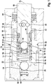
- FIG. 1 discloses a first embodiment of the invention, which is illustrated by a longitudinal section through an inserted into a pump receptacle of a housing block pump element.
- FIG. 2 shows a second embodiment of the invention with reference to a detailed diagram illustrating a separation point between a bushing of the pump element and a pump receptacle of a housing block.
- FIG. 1 a housing block of a hydraulic unit is designated by the reference numeral 10.
- This housing block 10 is provided with a pump receptacle 12, in which a pump element 14 is installed.
- the pump receptacle 12 is a bore which is open toward an outer side of the housing block 10 and which is repeatedly stepped down or withdrawn in its inner diameter from outside to inside.
- the pump element 14 inserted into the pump receptacle 12 includes, inter alia, a bushing 16 in which a piston 18 of the pump element 14 is received reciprocatingly guided.
- the bush 16 is cup-shaped and is closed at one of its ends by a bush bottom 20.
- a through hole In the center of this bushing bottom 20 is a through hole, which is further developed outside of the bush 16 to an exhaust valve seat 22.
- an exhaust valve closing member 24 in the form of a ball is provided, which is acted upon by an exhaust valve spring 26 against the exhaust valve seat 22.
- the exhaust valve closure member 24 abuts the exhaust valve seat 22 and blocks it.
- the bushing bottom 20 opposite end of the bushing 16 is open and received in the interior of the bushing 16 piston 18 is in sections from this opening. This is effected by a return spring 28 acting on the piston 18, which is arranged in the interior of the bushing 16 and which is supported on the inside of the bushing bottom 20. With its second end, the restoring spring 28 acts on a valve cage 30 of an inlet valve 32 of the pump element 14.
- the valve cage 30 is fixed to the bushing side end of the piston 18 and receives in its interior an inlet valve closing member 34 and an inlet valve spring 36 for actuating this inlet valve closing member 34.
- the valve cage 30 encloses an integral on the piston 18 axial extension 38, whose outer diameter is withdrawn relative to the piston 18.
- the axial extension 38 receives a sealing ring 40, which serves to seal the piston 18 in the bush 16.
- This sealing ring 40 is prestressed by the restoring spring 28 of the piston 18, which acts via the valve cage 30 on a first end face of the sealing ring 40.
- the opposite second end face of the sealing ring 40 bears against a rectangular shoulder 42 of the piston 18. This shoulder 42 results at the end of the axial extension 38 of the piston 18th
- the protruding from the bush 16 portion of the piston 18 is guided and sealed via a housing block side arranged sealing / guide ring assembly 44 in the pump holder 12.
- the piston 18 is provided with a blind hole-like longitudinal bore 46, which opens to the interior of the bushing 16 out.
- This longitudinal bore 46 is connected by a plurality of outwardly of the bushing 16 and distributed over the circumference of the piston 18 arranged transverse bores 48 with a piston 18 and ultimately to a pump inlet (not shown) leading low pressure region 50 of the pump element 14.
- the open end of the longitudinal bore 46 forms an inlet valve seat 52, the cross section of which is controlled by the inlet valve closing member 34.
- a pump chamber 54 Between the inlet valve seat 52 and the outlet valve seat 22 there is a pump chamber 54, the volume of which increases or decreases depending on the direction of movement of the piston 18.
- a high-pressure area 56 of the pump element 14 Downstream of the outlet valve seat 22, there is a high-pressure area 56 of the pump element 14, into which pressure medium flowing out of the outlet valve seat 22 flows.
- the high-pressure region 56 of the pump element 14 is ultimately contacted with a pump outlet, not shown.
- a sealing plug 58 which is pressed into the open towards the environment end of the pump holder 12 and additionally caulked from the outside with the housing block 10.
- the sealing plug 58 forms a receiving space 60, oriented towards the interior of the pump receptacle 12, for the outlet valve closing member 24 and for the outlet valve closing spring 26.
- the pump element 14 forms with the pump receptacle 12 a separation point 70 which is arranged between the low-pressure region 50 and the high-pressure region 56 of the pump element 14 in order to hydraulically separate these two regions from one another.
- the separation point 70 is divided into sections. In a first section 72, the pump element 14 is non-positively connected to the pump receptacle 12 and in a directly adjoining the first section 72 second portion 74, the pump element 14 is axially against the pump receptacle 12 of the housing block 10.
- the second section 74 thus forms an axial stop for the pump element 14 in the pump housing 12.
- the first, force-fit forming section 72 faces the high-pressure area 56 of the pump element 14.
- the pump receptacle 12 In the region of the adhesion-forming first portion 72 of the separation point 70, the pump receptacle 12 is reduced in its inner diameter. A transition from the larger diameter to the smaller diameter inner diameter of the pump holder 12 is designed as a ring bevel in order to simplify the assembly of the pump element 14.
- the bush 16 of the pump element 14 has an enlarged outer diameter in the first section 72 of the separation point 70. The outer diameter of the bushing 16 is matched to the inner diameter of the pump receptacle 12 such that adjusts a press connection with an installation of the pump element 14 in the pump receptacle 12 between the two parts, which rotates along the circumference of the pump element 14.
- the second section 74 of the separation point 70 directly adjoins the above-described first section 72 in the direction of a longitudinal axis 76 of the pump element 14. It is formed by an annular shoulder 78 which is shown on the inner circumference of the pump receptacle 12 or on the outer circumference of the bushing 16 and a correspondingly shaped counter-shoulder 80 which is circumferentially formed on the outer circumference of the bushing 16 or on the inner circumference of the pump receptacle 12. Shoulder 78 and counter-shoulder 80 in this embodiment form component tabs which enclose an angle between 30 ° and 60 °, preferably an angle of 45 °, relative to the longitudinal axis 76 of the pump element 14.
- the second section 74 of the separation point 70 represents a mechanical stop when pressing the pump element 14 into the pump receptacle 12. It lies according to the invention facing away from the high-pressure region 56 of the pump element 14 and comes through the invention according to the high-pressure region 56 of the pump element 14 facing and forming a frictional first portion 72 of the separation point 70 is not in high pressure pressure medium in contact.
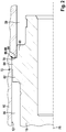
- FIG. 2 shows a second embodiment of the invention. Visible is a portion of a bushing 16 which is inserted into a pump receptacle 12.
- the bushing 16 forms with the pump receptacle 12, a separation point 70 also consisting of several sections or zones between the high pressure region 56 and the low pressure region 50 of a pump element 14 not shown in detail. Starting from the high-pressure region 56 of the pump element 14 and viewed in the direction of the longitudinal axis 76 of this pump element 14, a total of four sections are present. In section one 82, the bushing 16 of the pump element 14 forms a gap seal with the pump receptacle 12 of the housing block 10.
- Shoulder 78 and counter-shoulder 80 form planar surfaces which, viewed in the plane of the drawing, extend at a right angle (90 °) to a longitudinal axis of pump element 14 or bushing 16 of pump element 14.
- the pump element 14 strikes with its bushing 16 when it has been inserted into the pump receptacle 12 with a predetermined offset.
- an axially subsequent section four 90 again forms a frictional connection between bushing 16 and pump receptacle 12 by the diameter of the bush 16 is dimensioned slightly larger than the corresponding inner diameter of the pump receptacle 12.
- the diameters in the two adhesion-forming sections two and four 84, 90 are dimensioned differently large, wherein the diameter in section two 84 is greater than the diameter in section four 90 executed.
- the change in diameter between the sections two and four 84, 90 forms in this embodiment, the right-angled shoulder 78, against which the corresponding rectangular formed counter-shoulder 80 of the bush 16 abuts when the latter has reached its intended Einpresstiefe.
Landscapes
- Engineering & Computer Science (AREA)
- Mechanical Engineering (AREA)
- General Engineering & Computer Science (AREA)
- Transportation (AREA)
- Physics & Mathematics (AREA)
- Fluid Mechanics (AREA)
- Details Of Reciprocating Pumps (AREA)
- Valves And Accessory Devices For Braking Systems (AREA)
- Regulating Braking Force (AREA)
Description
- Die Erfindung betrifft ein Hydraulikaggregat insbesondere für eine schlupfregelbare Fahrzeugbremsanlage nach den gattungsbildenden Merkmalen des Anspruchs 1. Ein derartiges Hydraulikaggregat ist beispielsweise bekannt aus der
DE 10 2008 003 456 A1 . - Dieses bekannte Hydraulikaggregat hat einen Gehäuseblock, mit einer am Gehäuseblock ausgebildeten Pumpenaufnahme und einem in diese Pumpenaufnahme eingesetzten Pumpenelement. Das Pumpenelement bildet mit dem Gehäuseblock eine hydraulisch wirksame Trennstelle, welche einen Niederdruckbereich des Pumpenelements von einem Hochdruckbereich trennt. Diese Trennstelle ist gegliedert in einen Abschnitt, der einen Kraftschluss zwischen Gehäuseblock und Pumpenelement ausbildet und in einen zweiten Abschnitt an dem das Pumpenelement am Gehäuseblock axial anliegt.
- Im Anlagebereich liegt eine Schulter einer Laufbuchse zur Führung eines Kolbens des Pumpenelements an einer Gegenschulter an, welche an der inneren Wand der Pumpenaufnahme des Gehäuseblocks ausgebildet ist. Schulter und Gegenschulter sind dargestellt durch einander entgegen gerichtete Bauteilfasen. Diese wirken bei der Herstellung des Kraftschlusses zwischen Gehäuseblock und Pumpenelement als geometrischer Axialanschlag, welcher die auftretenden Einpresskräfte bzw. die maximale Einpresstiefe des Pumpenelements begrenzt.
- Beim bekannten Hydraulikaggregat ist der den Kraftschluss bildende Abschnitt dem Niederdruckbereich des Pumpenelements zugewandt, so dass unter hohem Druck stehendes Druckmittel aus dem Hochdruckbereich des Pumpenelements zum Anlagebereich bzw. zur Schulter des Pumpenelements und zur Gegenschulter der Pumpenaufnahme vordringen kann.
- Die Laufbuchse des Pumpenelements besteht aus Stahl, während der Gehäuseblock aus einer Aluminiumlegierung hergestellt ist. Zudem sind die Schulter sowie die Gegenschulter aufgrund ihrer Wirkung als mechanischer Axialanschlag beim Einpressen des Pumpenelements in die Pumpenaufnahme mechanischen Spannungen ausgesetzt. Die Summe dieser Umstände kann dazu führen, dass beim zitierten Stand der Technik unerwünschte Korrosion am Anschlagbereich der Trennstelle, also zwischen der Schulter und der Gegenschulter bzw. zwischen dem Gehäuseblock und dem Pumpenelement auftreten kann.
- Die Erfindung nach den Merkmalen des Anspruchs 1 weist demgegenüber den Vorteil auf, dass Korrosion im Anschlagbereich von Pumpenelement und Pumpenaufnahme verhindert wird. Dies wird dadurch erreicht, dass eine vorgesehene Trennstelle zwischen Hochdruckbereich und Niederdruckbereich des Pumpenelements einen Kraftschluss bildenden Abschnitt aufweist, der erfindungsgemäß dem Hochdruckbereich des Pumpenelements zugewandt ist. Der den Kraftschluss bildende Abschnitt verhindert, dass unter hohem Druck stehendes Druckmittel zum Anschlagbereich der Trennstelle vordringen kann. Eine Korrosion auslösende Wechselwirkung der unterschiedlichen Werkstoffe von Gehäuseblock und Pumpenelement mit der überlagerten hohen Beanspruchung des mechanischen Axialanschlags und dem unter hohen Druck stehenden Druckmittel als Elektrolyt kann sich dadurch nicht einstellen. Mit anderen Worten ermöglicht die Erfindung eine weitgehende Trennung des mechanisch hoch belasteten Axialanschlags zwischen Pumpenelement und Gehäuseblock von Druckmittel.
- Die vorgeschlagene Maßnahme ist ohne Zusatzaufwand umsetzbar und wirkt sich weder in einem zusätzlichen Bauraumbedarf noch in höheren Teile- oder Montagekosten aus.
Weitere Vorteile oder vorteilhafte Weiterbildungen der Erfindung ergeben sich aus den Unteransprüchen und/oder der nachfolgenden Beschreibung. - Besonders vorteilhaft ist, wenn die Trennstelle zwischen Hochdruckbereich und Niederdruckbereich des Pumpenelements in wenigstens drei Abschnitte gegliedert ist, von denen zwei Abschnitte jeweils einen Kraftschluss zwischen Pumpenelement und Gehäuseblock ausbilden, ein dritter Abschnitt als Axialanschlag des Pumpenelements am Gehäuseblock wirkt und dieser dritte Abschnitt zwischen den beiden kraftschlüssigen Abschnitten angeordnet ist. Durch diese Anordnung kann weder Druckmittel aus dem Hochdruckbereich des Pumpenelements noch Druckmittel aus dem Niederdruckbereich des Pumpenelements zu dem den Axialanschlag ausbildenden Abschnitt der Trennstelle vordringen. Der Axialanschlag bzw. der dritte Abschnitt der Trennstelle ist also weitgehend frei von Druckmittel bzw. trocken, wodurch sich Korrosionseffekte zwischen den Bauteilen noch wirksamer verhindern lassen.
- Fertigungstechnisch besonders einfach lässt sich ein Kraftschluss zwischen Pumpenelement und Gehäuseblock darstellen, indem die Außenabmessungen des Pumpenelements auf die Innenabmessungen der Pumpenaufnahme derart abgestimmt sind, dass das Pumpenelement mit seiner Montage in die Pumpenaufnahme wenigstens abschnittsweise in diese Pumpenaufnahme eingepresst ist. Zu einer Überwachung des Einpressvorgangs bei der Montage, z.B. hinsichtlich Einpresskraft oder Einpressmaß des Pumpenelements in die Pumpenaufnahme, ist vorteilhaft eine Schulter am Pumpengehäuse oder am Pumpenelement vorgesehen, die mit einer Gegenschulter am Pumpenelement oder am Pumpengehäuse zusammenwirkt. Schulter und Gegenschulter können dabei relativ zu einer Längsachse des Pumpenelements rechtwinklig oder angeschrägt ausgeführt werden, wobei die rechtwinklige Ausführung vorteilhafter Weise Radialbewegungen, beispielsweise bedingt durch unterschiedliche Wärmeausdehnung der Bauelemente, verhindert.
- Ausführungsbeispiele der Erfindung sind in der Zeichnung dargestellt und in der nachfolgenden Beschreibung näher erläutert.
- Die
Figur 1 offenbart ein erstes Ausführungsbeispiel der Erfindung, welches anhand eines Längsschnitts durch ein in eine Pumpenaufnahme eines Gehäuseblocks eingesetztes Pumpenelement dargestellt ist. -
Figur 2 zeigt ein zweites Ausführungsbeispiel der Erfindung anhand einer Detailskizze, welche eine Trennstelle zwischen einer Laufbuchse des Pumpenelements und einer Pumpenaufnahme eines Gehäuseblocks darstellt. - In
Figur 1 ist ein Gehäuseblock eines Hydraulikaggregats mit der Bezugsziffer 10 bezeichnet. Dieser Gehäuseblock 10 ist mit einer Pumpenaufnahme 12 versehen, in die ein Pumpenelement 14 eingebaut ist. Bei der Pumpenaufnahme 12 handelt es sich um eine zu einer Außenseite des Gehäuseblocks 10 hin offene Bohrung, die in ihrem Innendurchmesser von außen nach innen mehrfach abgesetzt bzw. zurückgenommen ist. - Das in die Pumpenaufnahme 12 eingesetzte Pumpenelement 14 umfasst unter anderem eine Laufbuchse 16, in der ein Kolben 18 des Pumpenelements 14 hin und her beweglich geführt aufgenommen ist. Die Laufbuchse 16 ist topfförmig ausgebildet und wird an einem ihrer Enden von einem Laufbuchsenboden 20 verschlossen. Im Zentrum dieses Laufbuchsenbodens 20 befindet sich eine Durchgangsöffnung, die außerhalb der Laufbuchse 16 zu einem Auslassventilsitz 22 weitergebildet ist. Zur Steuerung dieses Auslassventilsitzes 22 ist ein Auslassventilschließglied 24 in Form einer Kugel vorgesehen, das von einer Auslassventilfeder 26 gegen den Auslassventilsitz 22 beaufschlagt ist. In der Darstellung liegt das Auslassventilschließglied 24 am Auslassventilsitz 22 an und sperrt diesen ab.
- Das dem Laufbuchsenboden 20 gegenüberliegende Ende der Laufbuchse 16 ist offen und der im Inneren der Laufbuchse 16 aufgenommene Kolben 18 steht abschnittsweise aus dieser Öffnung vor. Dies wird bewirkt von einer den Kolben 18 beaufschlagenden Rückstellfeder 28, die im Inneren der Laufbuchse 16 angeordnet ist und die sich auf der Innenseite des Laufbuchsenbodens 20 abstützt. Mit ihrem zweiten Ende greift die Rückstellfeder 28 an einem Ventilkäfig 30 eines Einlassventils 32 des Pumpenelements 14 an. Der Ventilkäfig 30 ist am laufbuchsenseitigen Ende des Kolbens 18 befestigt und nimmt in seinem Inneren ein Einlassventilschließglied 34 sowie eine Einlassventilfeder 36 zur Betätigung dieses Einlassventilschließglieds 34 auf. Der Ventilkäfig 30 umschließt einen am Kolben 18 einteilig ausgebildeten Axialfortsatz 38, dessen Außendurchmesser gegenüber dem des Kolbens 18 zurückgenommen ist. Der Axialfortsatz 38 nimmt einen Dichtungsring 40 auf, welcher der Abdichtung des Kolbens 18 in der Laufbuchse 16 dient. Vorgespannt wird dieser Dichtungsring 40 von der Rückstellfeder 28 des Kolbens 18, welche über den Ventilkäfig 30 an einer ersten Stirnseite des Dichtungsrings 40 angreift. Die dazu gegenüberliegende zweite Stirnseite des Dichtungsrings 40 liegt an einer rechtwinkligen Schulter 42 des Kolbens 18 an. Diese Schulter 42 ergibt sich am Ende des Axialfortsatzes 38 des Kolbens 18.
- Der aus der Laufbuchse 16 vorstehende Abschnitt des Kolbens 18 wird über eine gehäuseblockseitig angeordnete Dicht-/Führungsringanordnung 44 in der Pumpenaufnahme 12 geführt und abgedichtet.
- Der Kolben 18 ist mit einer sacklochartigen Längsbohrung 46 versehen, die zum Inneren der Laufbuchse 16 hin ausmündet. Diese Längsbohrung 46 wird durch mehrere außerhalb der Laufbuchse 16 ausmündende und über den Umfang des Kolbens 18 verteilt angeordnete Querbohrungen 48 mit einem den Kolben 18 umgebenden und letztlich zu einem Pumpeneinlass (nicht gezeigt) hinführenden Niederdruckbereich 50 des Pumpenelements 14 verbunden. Das offene Ende der Längsbohrung 46 bildet einen Einlassventilsitz 52, dessen Querschnitt vom Einlassventilschließglied 34 gesteuert ist. Zwischen dem Einlassventilsitz 52 und dem Auslassventilsitz 22 befindet sich ein Pumpenraum 54, dessen Volumen sich abhängig von der Bewegungsrichtung des Kolbens 18 vergrößert oder verkleinert.
- Stromabwärts des Auslassventilsitzes 22 befindet sich ein Hochdruckbereich 56 des Pumpenelements 14, in den aus dem Auslassventilsitz 22 abströmendes Druckmittel einströmt. Der Hochdruckbereich 56 des Pumpenelements 14 ist letztlich mit einem nicht gezeigten Pumpenauslass kontaktiert. Gegenüber der Umgebung ist der Hochdruckbereich 56 des Pumpenelements 14 durch einen Verschlussstopfen 58 abgedichtet, der in das zur Umgebung hin offene Ende der Pumpenaufnahme 12 eingepresst und zusätzlich von außen mit dem Gehäuseblock 10 verstemmt ist. Der Verschlussstopfen 58 bildet einen zum Inneren der Pumpenaufnahme 12 ausgerichteten Aufnahmeraum 60 für das Auslassventilschließglied 24 und für die Auslassventilschließfeder 26 aus.
- Das Pumpenelement 14 bildet mit der Pumpenaufnahme 12 eine Trennstelle 70 aus, die zwischen dem Niederdruckbereich 50 und dem Hochdruckbereich 56 des Pumpenelements 14 angeordnet ist, um diese beiden Bereiche hydraulisch voneinander zu trennen. Die Trennstelle 70 gliedert sich in Abschnitte. In einem ersten Abschnitt 72 ist das Pumpenelement 14 mit der Pumpenaufnahme 12 kraftschlüssig verbunden und in einem sich unmittelbar an den ersten Abschnitt 72 anschließenden zweiten Abschnitt 74 liegt das Pumpenelement 14 axial an der Pumpenaufnahme 12 des Gehäuseblocks 10 an. Der zweite Abschnitt 74 bildet somit einen Axialanschlag für das Pumpenelement 14 in der Pumpenaufnahme 12. Erfindungsgemäß ist der erste, einen Kraftschluss ausbildende Abschnitt 72 dem Hochdruckbereich 56 des Pumpenelements 14 zugewandt.
- Im Bereich des den Kraftschluss ausbildenden ersten Abschnitts 72 der Trennstelle 70 ist die Pumpenaufnahme 12 in ihrem Innendurchmesser reduziert. Ein Übergang vom durchmessergrößeren zum durchmesserkleineren Innendurchmesser der Pumpenaufnahme 12 ist als Ringfase ausgeführt, um die Montage des Pumpenelements 14 zu vereinfachen. Die Laufbuchse 16 des Pumpenelements 14 weist im ersten Abschnitt 72 der Trennstelle 70 einen vergrößerten Außendurchmesser auf. Der Außendurchmesser der Laufbuchse 16 ist dabei auf den Innendurchmesser der Pumpenaufnahme 12 derart abgestimmt, dass sich mit einem Einbau des Pumpenelements 14 in die Pumpenaufnahme 12 zwischen beiden Teilen eine Pressverbindung einstellt, die entlang des Umfangs des Pumpenelements 14 umläuft.
- Der zweite Abschnitt 74 der Trennstelle 70 grenzt in Richtung einer Längsachse 76 des Pumpenelements 14 unmittelbar an den oben beschriebenen ersten Abschnitt 72 an. Er wird gebildet durch eine ringförmige Schulter 78, die am Innenumfang der Pumpenaufnahme 12 oder am Außenumfang der Laufbuchse 16 dargestellt ist und eine entsprechend geformte Gegenschulter 80, welche umlaufend am Außenumfang der Laufbuchse 16 oder am Innenumfang der Pumpenaufnahme 12 ausgebildet ist. Schulter 78 und Gegenschulter 80 bilden bei diesem Ausführungsbeispiel Bauteilfasen, die relativ zur Längsachse 76 des Pumpenelements 14 einen Winkel zwischen 30° und 60°, vorzugsweise einen Winkel von 45° einschließen.
- Der zweite Abschnitt 74 der Trennstelle 70 stellt einen mechanischen Anschlag beim Einpressen des Pumpenelements 14 in die Pumpenaufnahme 12 dar. Er liegt erfindungsgemäß abgewandt vom Hochdruckbereich 56 des Pumpenelements 14 und kommt durch den erfindungsgemäß dem Hochdruckbereich 56 des Pumpenelements 14 zugewandten und einen Kraftschluss ausbildenden ersten Abschnitt 72 der Trennstelle 70 nicht mit unter Hochdruck stehendem Druckmittel in Berührung.
-
Figur 2 zeigt ein zweites Ausführungsbeispiel der Erfindung. Erkennbar ist ein Abschnitt einer Laufbuchse 16, die in eine Pumpenaufnahme 12 eingesetzt ist. Die Laufbuchse 16 bildet mit der Pumpenaufnahme 12 eine ebenfalls aus mehreren Abschnitten oder Zonen bestehende Trennstelle 70 zwischen dem Hochdruckbereich 56 und dem Niederdruckbereich 50 eines nicht detailliert dargestellten Pumpenelements 14 aus. Ausgehend vom Hochdruckbereich 56 des Pumpenelements 14 und in Richtung der Längsachse 76 dieses Pumpenelements 14 betrachtet, sind insgesamt vier Abschnitte vorhanden. In Abschnitt eins 82 bildet die Laufbuchse 16 des Pumpenelements 14 eine Spaltdichtung mit der Pumpenaufnahme 12 des Gehäuseblocks 10 aus. Dies wird erreicht durch einen Außendurchmesser der Laufbuchse 16, der in dieser Zone (Abschnitt eins) nur geringfügig kleiner ist, als der zugeordnete Innendurchmesser der Pumpenaufnahme 12. In einem nachfolgenden Abschnitt zwei 84 besteht zwischen Laufbuchse 16 und Pumpenaufnahme 12 ein Kraftschluss bzw. eine Pressverbindung. Dazu ist der Außendurchmesser der Laufbuchse 16 geringfügig größer bemessen, als der zugeordnete Innendurchmesser der Pumpenaufnahme 12. In einem Abschnitt drei 86 liegt das Pumpenelement an einem Axialanschlag 88 an. Dazu bildet die Pumpenaufnahme 12 eine Schulter 78 aus, an der eine Gegenschulter 80 der Laufbuchse 16 anliegt. Schulter 78 und Gegenschulter 80 bilden ebene Flächen, die, in der Zeichenebene betrachtet, unter Einschluss eines rechten Winkels (90°) zu einer Längsachse des Pumpenelements 14 bzw. der Laufbuchse 16 des Pumpenelements 14 verlaufen. An diesem Axialanschlag 88 schlägt das Pumpenelement 14 mit seiner Laufbuchse 16 an, wenn diese mit einer festgelegten Einpresstiefe in die Pumpenaufnahme 12 eingesetzt worden ist. Ein sich darüber hinaus axial anschließender Abschnitt vier 90 bildet erneut einen Kraftschluss zwischen Laufbuchse 16 und Pumpenaufnahme 12 indem der Durchmesser der Laufbuchse 16 geringfügig größer als der entsprechende Innendurchmesser der Pumpenaufnahme 12 bemessen ist. Die Durchmesser in den beiden Kraftschluss bildenden Abschnitten zwei und vier 84, 90 sind unterschiedliche groß bemessen, wobei der Durchmesser in Abschnitt zwei 84 größer als der Durchmesser in Abschnitt vier 90 ausgeführt ist. Die Durchmesseränderung zwischen den Abschnitten zwei und vier 84, 90 bildet bei diesem Ausführungsbeispiel die rechtwinklige Schulter 78 aus, gegen welche die entsprechend rechtwinklig ausgebildete Gegenschulter 80 der Laufbuchse 16 anschlägt, sobald Letztere ihre vorgesehene Einpresstiefe erreicht hat. - Die beiden jeweils einen Kraftschluss zwischen Pumpenelement 14 und Pumpenaufnahme 12 bildenden Abschnitte zwei und vier 84, 90 verhindern bei diesem zweiten Ausführungsbeispiel, dass Druckmittel aus dem Hochdruckbereich 56 oder Druckmittel aus dem Niederdruckbereich 50 des Pumpenelements 14 zum Axialanschlag 88 zwischen Pumpenelement 14 und Pumpenaufnahme 12 bildenden Abschnitt drei 86 der Trennstelle 70 gelangt. Sie dichten demnach Abschnitt drei 86 gegen eintretendes Druckmittel ab und verhindern dadurch Korrosion zwischen Schulter 78 und Gegenschulter 80 an Pumpenelement 14 und/oder an der Pumpenaufnahme 12.
Claims (8)
- Hydraulikaggregat, insbesondere für eine schlupfregelbare Fahrzeugbremsanlage, mit einem Gehäuseblock (10), einer am Gehäuseblock (10) ausgebildeten Pumpenaufnahme (12) und einem in die Pumpenaufnahme (12) eingesetzten Pumpenelement (14), wobei das Pumpenelement (14) mit dem Gehäuseblock (10) eine Trennstelle (70) ausbildet, die einen mit einem Pumpeneinlass kontaktierten Niederdruckbereich (50) des Pumpenelements (14) von einem mit einem Pumpenauslass kontaktierten Hochdruckbereich (56) des Pumpenelements (14) hydraulisch trennt und wobei die Trennstelle (70) wenigstens einen ersten Abschnitt (72; 84), an dem das Pumpenelement (14) mit dem Gehäuseblock (10) durch einen Kraftschluss verbunden ist und einen zweiten Abschnitt (74; 86), an dem das Pumpenelement (14) mit dem Gehäuseblock (10) einen Axialanschlag ausbildet, aufweist,
dadurch gekennzeichnet,
dass der den Kraftschluss ausbildende Abschnitt (72; 84) der Trennstelle (70) dem Hochruckbereich (56) des Pumpenelements (14) zugewandt liegt. - Hydraulikaggregat nach Anspruch 1, dadurch gekennzeichnet, dass die Trennstelle (70) einen zusätzlichen dritten Abschnitt (90) aufweist, an dem das Pumpenelement (14) durch einen Kraftschluss mit dem Gehäuseblock (10) verbunden ist, wobei dieser dritte Abschnitt (90) der Trennstelle (70) dem Niederdruckbereich (50) des Pumpenelements (14) zugewandt liegt und wobei der den Axialanschlag ausbildende zweite Abschnitt (74; 86) der Trennstelle (70) zwischen den Kraftschluss bildenden ersten und zweiten Abschnitten (84, 90) der Trennstelle (70) angeordnet ist.
- Hydraulikaggregat nach Anspruch 1 oder 2, dadurch gekennzeichnet, dass die einen Kraftschluss bildenden Abschnitte (72; 84) und der einen Axialanschlag (88) bildende Abschnitt (74; 86) der Trennstelle (70) in Richtung einer Längsachse (76) des Pumpenelements (14) unmittelbar aneinander angrenzen.
- Hydraulikaggregat nach einem der Ansprüche 1 bis 3, dadurch gekennzeichnet, dass der Kraftschluss zwischen Pumpenelement (14) und Pumpenaufnahme (12) am Gehäuseblock (10) als Pressverbindung zwischen beiden Bauteilen ausgebildet ist.
- Hydraulikaggregat nach Anspruch 4, dadurch gekennzeichnet, dass der einen Axialanschlag (88) bildende Abschnitt (74; 86) der Trennstelle (70) eine am Gehäuseblock (10) oder am Pumpenelement (14) ausgebildete Schulter (78) und eine am Pumpenelement (14) oder am Gehäuseblock (10) ausgebildete Gegenschulter (80) umfasst.
- Hydraulikaggregat nach Anspruch 5, dadurch gekennzeichnet, dass die Schulter (78) und die Gegenschulter (80) mit der Längsachse (76) des Pumpenelements (14) einen Winkel von 90° oder einen Winkel zwischen 30° und 60°, vorzugsweise von 45°, einschließen.
- Hydraulikaggregat nach einem der Ansprüche 1 bis 6, dadurch gekennzeichnet, dass das Pumpenelement (14) mit einer Laufbuchse (16) zur Führung eines Kolbens (18) des Pumpenelements (14) ausgestattet ist und dass die Laufbuchse (16) mit einer Innenwandung der Pumpenaufnahme (12) des Gehäuseblocks (10) die Trennstelle (70) ausbildet.
- Hydraulikaggregat nach einem der Ansprüche 1 bis 7, dadurch gekennzeichnet, dass die Pumpenaufnahme (12) am Gehäuseblock (10) von einer nach außen offenen und in ihrem Innendurchmesser abgestuften Bohrung gebildet ist, wobei das offene Ende der Pumpenaufnahme (12) mit einem Verschlussstopfen (58) verschlossen ist, an welchem das Pumpenelement (14) abgestützt ist.
Applications Claiming Priority (2)
| Application Number | Priority Date | Filing Date | Title |
|---|---|---|---|
| DE102013226817.3A DE102013226817A1 (de) | 2013-12-20 | 2013-12-20 | Hydraulikaggregat |
| PCT/EP2014/078319 WO2015091700A1 (de) | 2013-12-20 | 2014-12-17 | Hydraulikaggregat |
Publications (2)
| Publication Number | Publication Date |
|---|---|
| EP3083352A1 EP3083352A1 (de) | 2016-10-26 |
| EP3083352B1 true EP3083352B1 (de) | 2017-08-23 |
Family
ID=52292905
Family Applications (1)
| Application Number | Title | Priority Date | Filing Date |
|---|---|---|---|
| EP14824444.5A Active EP3083352B1 (de) | 2013-12-20 | 2014-12-17 | Hydraulikaggregat |
Country Status (7)
| Country | Link |
|---|---|
| US (1) | US20160311417A1 (de) |
| EP (1) | EP3083352B1 (de) |
| JP (1) | JP6313856B2 (de) |
| KR (1) | KR102410067B1 (de) |
| CN (1) | CN105899415B (de) |
| DE (1) | DE102013226817A1 (de) |
| WO (1) | WO2015091700A1 (de) |
Family Cites Families (12)
| Publication number | Priority date | Publication date | Assignee | Title |
|---|---|---|---|---|
| DE19508636A1 (de) * | 1995-03-10 | 1996-09-12 | Bosch Gmbh Robert | Kraftstoffeinspritzventil für Brennkraftmaschinen |
| DE19732791A1 (de) * | 1997-07-30 | 1999-02-04 | Bosch Gmbh Robert | Kolbenpumpe |
| DE10314979B3 (de) * | 2003-04-02 | 2004-12-02 | Robert Bosch Gmbh | Kolbenpumpe |
| DE102005042196A1 (de) * | 2005-09-06 | 2007-03-08 | Robert Bosch Gmbh | Kolbenpumpe mit reduziertem Schadraum |
| US8011289B2 (en) * | 2006-01-13 | 2011-09-06 | Bwi Company Limited S.A. | Half-sleeved and sleeveless plastic piston pumps |
| DE102007052756A1 (de) * | 2007-11-06 | 2009-05-07 | Robert Bosch Gmbh | Kunststoffelement, Kolbenpumpe sowie Montageverfahren |
| DE102008003456A1 (de) * | 2008-01-08 | 2009-07-09 | Robert Bosch Gmbh | Hydraulikfluidpumpe mit einem Dichtring |
| DE102008002740A1 (de) * | 2008-06-27 | 2009-12-31 | Robert Bosch Gmbh | Kolbenpumpe |
| DE102009055228A1 (de) * | 2009-12-23 | 2011-06-30 | Robert Bosch GmbH, 70469 | Kolbenpumpe für eine hydraulische Fahrzeugbremsanlage |
| DE102010039507A1 (de) * | 2010-08-19 | 2012-02-23 | Robert Bosch Gmbh | Kolbenführungselement |
| DE102012213763A1 (de) * | 2012-08-03 | 2014-02-06 | Robert Bosch Gmbh | Niederdruckdichtring für ein Pumpenelement eines Hydraulikaggregats |
| DE102012214355A1 (de) * | 2012-08-13 | 2014-02-13 | Robert Bosch Gmbh | Führungsring für ein Pumpenelement einer Fahrzeugbremsanlage |
-
2013
- 2013-12-20 DE DE102013226817.3A patent/DE102013226817A1/de not_active Withdrawn
-
2014
- 2014-12-17 KR KR1020167016290A patent/KR102410067B1/ko active Active
- 2014-12-17 EP EP14824444.5A patent/EP3083352B1/de active Active
- 2014-12-17 US US15/104,266 patent/US20160311417A1/en not_active Abandoned
- 2014-12-17 JP JP2016531023A patent/JP6313856B2/ja active Active
- 2014-12-17 CN CN201480068645.7A patent/CN105899415B/zh active Active
- 2014-12-17 WO PCT/EP2014/078319 patent/WO2015091700A1/de not_active Ceased
Non-Patent Citations (1)
| Title |
|---|
| None * |
Also Published As
| Publication number | Publication date |
|---|---|
| KR102410067B1 (ko) | 2022-06-20 |
| JP6313856B2 (ja) | 2018-04-18 |
| EP3083352A1 (de) | 2016-10-26 |
| US20160311417A1 (en) | 2016-10-27 |
| WO2015091700A1 (de) | 2015-06-25 |
| CN105899415A (zh) | 2016-08-24 |
| CN105899415B (zh) | 2018-11-16 |
| DE102013226817A1 (de) | 2015-06-25 |
| KR20160100308A (ko) | 2016-08-23 |
| JP2017501070A (ja) | 2017-01-12 |
Similar Documents
| Publication | Publication Date | Title |
|---|---|---|
| EP2193282B1 (de) | Hydraulisches element | |
| EP2205865B1 (de) | Kolbenpumpe zur förderung eines fluids und zugehöriges bremssystem | |
| EP2207960A1 (de) | Kunststoffelement, kolbenpumpe sowie montageverfahren | |
| DE102014010570A1 (de) | Kupplungsteil für eine Kupplung für Druckmittelleitungen | |
| EP2283227A1 (de) | Federhaltehülse | |
| DE102010018200A1 (de) | Steuerventil, insbesondere Proportionalventil | |
| EP2564040B1 (de) | Druckspeicheranordnung für ein nockenwellenverstellsystem | |
| WO2021018341A1 (de) | Ventil und vorrichtung zur regelung von drücken eines strömungsmittels mit dem ventil sowie vorrichtung zur sicherung des ventils in dem getriebebauteil | |
| DE102018117451A1 (de) | Rückschlagventil für einen Pleuel einer Brennkraftmaschine mit variabler Verdichtung sowie Pleuel mit einem derartigen Rückschlagventil | |
| DE102015200538A1 (de) | Nockenwellenversteller | |
| EP3083352B1 (de) | Hydraulikaggregat | |
| DE10134069A1 (de) | Kraftstoffpumpe für ein Kraftstoffsystem einer Brennkraftmaschine | |
| EP4469672B1 (de) | Zylinderkopf für eine brennkraftmaschine mit einem brennraum und die verwendung einer dichthülse zum abdichten eines zylinderkopfes | |
| EP1317328B1 (de) | Verstemmstempel und verwendung desselben | |
| EP2905669A2 (de) | Druckregelventil | |
| DE102018107108A1 (de) | Umschaltventil zum Steuern eines Hydraulikflüssigkeitsstroms und Pleuel für eine Brennkraftmaschine mit variabler Verdichtung mit einem Umschaltventil | |
| EP3361069B1 (de) | Pleuel einer brennkraftmaschine mit variabler verdichtung mit einem rückschlagventil | |
| DE102017106987A1 (de) | Rückschlagventil für ein Pleuel für eine Brennkraftmaschine mit variabler Verdichtung | |
| DE3202405C2 (de) | Kraftstoffeinspritzpumpe für Brennkraftmaschinen | |
| DE102008027242B4 (de) | Verfahren zum Montieren einer Klappe in einem Gehäuse | |
| DE102018110030B4 (de) | Hydraulische Spannvorrichtung für einen Kettentrieb | |
| EP1208321A1 (de) | Ventil zum steuern von flüssigkeiten | |
| DE102008003212A1 (de) | Druckventil mit hydraulischer Dichtung, insbesondere metallischer Dichtung | |
| EP3514418B1 (de) | Einbauventil für einen ventilblock | |
| DE102015213693A1 (de) | Hydraulische Ventilanordnung und Verfahren zum Montieren einer derartigen Ventilanordnung |
Legal Events
| Date | Code | Title | Description |
|---|---|---|---|
| PUAI | Public reference made under article 153(3) epc to a published international application that has entered the european phase |
Free format text: ORIGINAL CODE: 0009012 |
|
| 17P | Request for examination filed |
Effective date: 20160720 |
|
| AK | Designated contracting states |
Kind code of ref document: A1 Designated state(s): AL AT BE BG CH CY CZ DE DK EE ES FI FR GB GR HR HU IE IS IT LI LT LU LV MC MK MT NL NO PL PT RO RS SE SI SK SM TR |
|
| AX | Request for extension of the european patent |
Extension state: BA ME |
|
| DAX | Request for extension of the european patent (deleted) | ||
| GRAP | Despatch of communication of intention to grant a patent |
Free format text: ORIGINAL CODE: EPIDOSNIGR1 |
|
| INTG | Intention to grant announced |
Effective date: 20170518 |
|
| GRAS | Grant fee paid |
Free format text: ORIGINAL CODE: EPIDOSNIGR3 |
|
| GRAA | (expected) grant |
Free format text: ORIGINAL CODE: 0009210 |
|
| AK | Designated contracting states |
Kind code of ref document: B1 Designated state(s): AL AT BE BG CH CY CZ DE DK EE ES FI FR GB GR HR HU IE IS IT LI LT LU LV MC MK MT NL NO PL PT RO RS SE SI SK SM TR |
|
| REG | Reference to a national code |
Ref country code: GB Ref legal event code: FG4D Free format text: NOT ENGLISH |
|
| REG | Reference to a national code |
Ref country code: CH Ref legal event code: EP |
|
| REG | Reference to a national code |
Ref country code: AT Ref legal event code: REF Ref document number: 920970 Country of ref document: AT Kind code of ref document: T Effective date: 20170915 |
|
| REG | Reference to a national code |
Ref country code: IE Ref legal event code: FG4D Free format text: LANGUAGE OF EP DOCUMENT: GERMAN |
|
| REG | Reference to a national code |
Ref country code: DE Ref legal event code: R096 Ref document number: 502014005193 Country of ref document: DE |
|
| REG | Reference to a national code |
Ref country code: FR Ref legal event code: PLFP Year of fee payment: 4 |
|
| REG | Reference to a national code |
Ref country code: NL Ref legal event code: MP Effective date: 20170823 |
|
| REG | Reference to a national code |
Ref country code: LT Ref legal event code: MG4D |
|
| PG25 | Lapsed in a contracting state [announced via postgrant information from national office to epo] |
Ref country code: NO Free format text: LAPSE BECAUSE OF FAILURE TO SUBMIT A TRANSLATION OF THE DESCRIPTION OR TO PAY THE FEE WITHIN THE PRESCRIBED TIME-LIMIT Effective date: 20171123 Ref country code: NL Free format text: LAPSE BECAUSE OF FAILURE TO SUBMIT A TRANSLATION OF THE DESCRIPTION OR TO PAY THE FEE WITHIN THE PRESCRIBED TIME-LIMIT Effective date: 20170823 Ref country code: FI Free format text: LAPSE BECAUSE OF FAILURE TO SUBMIT A TRANSLATION OF THE DESCRIPTION OR TO PAY THE FEE WITHIN THE PRESCRIBED TIME-LIMIT Effective date: 20170823 Ref country code: HR Free format text: LAPSE BECAUSE OF FAILURE TO SUBMIT A TRANSLATION OF THE DESCRIPTION OR TO PAY THE FEE WITHIN THE PRESCRIBED TIME-LIMIT Effective date: 20170823 Ref country code: LT Free format text: LAPSE BECAUSE OF FAILURE TO SUBMIT A TRANSLATION OF THE DESCRIPTION OR TO PAY THE FEE WITHIN THE PRESCRIBED TIME-LIMIT Effective date: 20170823 Ref country code: SE Free format text: LAPSE BECAUSE OF FAILURE TO SUBMIT A TRANSLATION OF THE DESCRIPTION OR TO PAY THE FEE WITHIN THE PRESCRIBED TIME-LIMIT Effective date: 20170823 |
|
| PG25 | Lapsed in a contracting state [announced via postgrant information from national office to epo] |
Ref country code: PL Free format text: LAPSE BECAUSE OF FAILURE TO SUBMIT A TRANSLATION OF THE DESCRIPTION OR TO PAY THE FEE WITHIN THE PRESCRIBED TIME-LIMIT Effective date: 20170823 Ref country code: GR Free format text: LAPSE BECAUSE OF FAILURE TO SUBMIT A TRANSLATION OF THE DESCRIPTION OR TO PAY THE FEE WITHIN THE PRESCRIBED TIME-LIMIT Effective date: 20171124 Ref country code: IS Free format text: LAPSE BECAUSE OF FAILURE TO SUBMIT A TRANSLATION OF THE DESCRIPTION OR TO PAY THE FEE WITHIN THE PRESCRIBED TIME-LIMIT Effective date: 20171223 Ref country code: BG Free format text: LAPSE BECAUSE OF FAILURE TO SUBMIT A TRANSLATION OF THE DESCRIPTION OR TO PAY THE FEE WITHIN THE PRESCRIBED TIME-LIMIT Effective date: 20171123 Ref country code: LV Free format text: LAPSE BECAUSE OF FAILURE TO SUBMIT A TRANSLATION OF THE DESCRIPTION OR TO PAY THE FEE WITHIN THE PRESCRIBED TIME-LIMIT Effective date: 20170823 Ref country code: RS Free format text: LAPSE BECAUSE OF FAILURE TO SUBMIT A TRANSLATION OF THE DESCRIPTION OR TO PAY THE FEE WITHIN THE PRESCRIBED TIME-LIMIT Effective date: 20170823 Ref country code: ES Free format text: LAPSE BECAUSE OF FAILURE TO SUBMIT A TRANSLATION OF THE DESCRIPTION OR TO PAY THE FEE WITHIN THE PRESCRIBED TIME-LIMIT Effective date: 20170823 |
|
| PG25 | Lapsed in a contracting state [announced via postgrant information from national office to epo] |
Ref country code: DK Free format text: LAPSE BECAUSE OF FAILURE TO SUBMIT A TRANSLATION OF THE DESCRIPTION OR TO PAY THE FEE WITHIN THE PRESCRIBED TIME-LIMIT Effective date: 20170823 Ref country code: CZ Free format text: LAPSE BECAUSE OF FAILURE TO SUBMIT A TRANSLATION OF THE DESCRIPTION OR TO PAY THE FEE WITHIN THE PRESCRIBED TIME-LIMIT Effective date: 20170823 |
|
| REG | Reference to a national code |
Ref country code: DE Ref legal event code: R097 Ref document number: 502014005193 Country of ref document: DE |
|
| PG25 | Lapsed in a contracting state [announced via postgrant information from national office to epo] |
Ref country code: SM Free format text: LAPSE BECAUSE OF FAILURE TO SUBMIT A TRANSLATION OF THE DESCRIPTION OR TO PAY THE FEE WITHIN THE PRESCRIBED TIME-LIMIT Effective date: 20170823 Ref country code: SK Free format text: LAPSE BECAUSE OF FAILURE TO SUBMIT A TRANSLATION OF THE DESCRIPTION OR TO PAY THE FEE WITHIN THE PRESCRIBED TIME-LIMIT Effective date: 20170823 Ref country code: EE Free format text: LAPSE BECAUSE OF FAILURE TO SUBMIT A TRANSLATION OF THE DESCRIPTION OR TO PAY THE FEE WITHIN THE PRESCRIBED TIME-LIMIT Effective date: 20170823 Ref country code: IT Free format text: LAPSE BECAUSE OF FAILURE TO SUBMIT A TRANSLATION OF THE DESCRIPTION OR TO PAY THE FEE WITHIN THE PRESCRIBED TIME-LIMIT Effective date: 20170823 |
|
| PLBE | No opposition filed within time limit |
Free format text: ORIGINAL CODE: 0009261 |
|
| STAA | Information on the status of an ep patent application or granted ep patent |
Free format text: STATUS: NO OPPOSITION FILED WITHIN TIME LIMIT |
|
| REG | Reference to a national code |
Ref country code: CH Ref legal event code: PL |
|
| 26N | No opposition filed |
Effective date: 20180524 |
|
| PG25 | Lapsed in a contracting state [announced via postgrant information from national office to epo] |
Ref country code: SI Free format text: LAPSE BECAUSE OF FAILURE TO SUBMIT A TRANSLATION OF THE DESCRIPTION OR TO PAY THE FEE WITHIN THE PRESCRIBED TIME-LIMIT Effective date: 20170823 |
|
| REG | Reference to a national code |
Ref country code: IE Ref legal event code: MM4A |
|
| PG25 | Lapsed in a contracting state [announced via postgrant information from national office to epo] |
Ref country code: MT Free format text: LAPSE BECAUSE OF FAILURE TO SUBMIT A TRANSLATION OF THE DESCRIPTION OR TO PAY THE FEE WITHIN THE PRESCRIBED TIME-LIMIT Effective date: 20170823 Ref country code: LU Free format text: LAPSE BECAUSE OF NON-PAYMENT OF DUE FEES Effective date: 20171217 |
|
| REG | Reference to a national code |
Ref country code: BE Ref legal event code: MM Effective date: 20171231 |
|
| PG25 | Lapsed in a contracting state [announced via postgrant information from national office to epo] |
Ref country code: IE Free format text: LAPSE BECAUSE OF NON-PAYMENT OF DUE FEES Effective date: 20171217 |
|
| PG25 | Lapsed in a contracting state [announced via postgrant information from national office to epo] |
Ref country code: BE Free format text: LAPSE BECAUSE OF NON-PAYMENT OF DUE FEES Effective date: 20171231 Ref country code: CH Free format text: LAPSE BECAUSE OF NON-PAYMENT OF DUE FEES Effective date: 20171231 Ref country code: LI Free format text: LAPSE BECAUSE OF NON-PAYMENT OF DUE FEES Effective date: 20171231 |
|
| PG25 | Lapsed in a contracting state [announced via postgrant information from national office to epo] |
Ref country code: HU Free format text: LAPSE BECAUSE OF FAILURE TO SUBMIT A TRANSLATION OF THE DESCRIPTION OR TO PAY THE FEE WITHIN THE PRESCRIBED TIME-LIMIT; INVALID AB INITIO Effective date: 20141217 Ref country code: MC Free format text: LAPSE BECAUSE OF FAILURE TO SUBMIT A TRANSLATION OF THE DESCRIPTION OR TO PAY THE FEE WITHIN THE PRESCRIBED TIME-LIMIT Effective date: 20170823 |
|
| PG25 | Lapsed in a contracting state [announced via postgrant information from national office to epo] |
Ref country code: RO Free format text: LAPSE BECAUSE OF FAILURE TO SUBMIT A TRANSLATION OF THE DESCRIPTION OR TO PAY THE FEE WITHIN THE PRESCRIBED TIME-LIMIT Effective date: 20170823 |
|
| PG25 | Lapsed in a contracting state [announced via postgrant information from national office to epo] |
Ref country code: CY Free format text: LAPSE BECAUSE OF FAILURE TO SUBMIT A TRANSLATION OF THE DESCRIPTION OR TO PAY THE FEE WITHIN THE PRESCRIBED TIME-LIMIT Effective date: 20170823 |
|
| PG25 | Lapsed in a contracting state [announced via postgrant information from national office to epo] |
Ref country code: MK Free format text: LAPSE BECAUSE OF FAILURE TO SUBMIT A TRANSLATION OF THE DESCRIPTION OR TO PAY THE FEE WITHIN THE PRESCRIBED TIME-LIMIT Effective date: 20170823 |
|
| PG25 | Lapsed in a contracting state [announced via postgrant information from national office to epo] |
Ref country code: TR Free format text: LAPSE BECAUSE OF FAILURE TO SUBMIT A TRANSLATION OF THE DESCRIPTION OR TO PAY THE FEE WITHIN THE PRESCRIBED TIME-LIMIT Effective date: 20170823 |
|
| PG25 | Lapsed in a contracting state [announced via postgrant information from national office to epo] |
Ref country code: PT Free format text: LAPSE BECAUSE OF FAILURE TO SUBMIT A TRANSLATION OF THE DESCRIPTION OR TO PAY THE FEE WITHIN THE PRESCRIBED TIME-LIMIT Effective date: 20170823 |
|
| PG25 | Lapsed in a contracting state [announced via postgrant information from national office to epo] |
Ref country code: AL Free format text: LAPSE BECAUSE OF FAILURE TO SUBMIT A TRANSLATION OF THE DESCRIPTION OR TO PAY THE FEE WITHIN THE PRESCRIBED TIME-LIMIT Effective date: 20170823 |
|
| REG | Reference to a national code |
Ref country code: AT Ref legal event code: MM01 Ref document number: 920970 Country of ref document: AT Kind code of ref document: T Effective date: 20191217 |
|
| PG25 | Lapsed in a contracting state [announced via postgrant information from national office to epo] |
Ref country code: AT Free format text: LAPSE BECAUSE OF NON-PAYMENT OF DUE FEES Effective date: 20191217 |
|
| PGFP | Annual fee paid to national office [announced via postgrant information from national office to epo] |
Ref country code: GB Payment date: 20251218 Year of fee payment: 12 |
|
| PGFP | Annual fee paid to national office [announced via postgrant information from national office to epo] |
Ref country code: FR Payment date: 20251218 Year of fee payment: 12 |
|
| PGFP | Annual fee paid to national office [announced via postgrant information from national office to epo] |
Ref country code: DE Payment date: 20260223 Year of fee payment: 12 |