EP3083349B1 - Automatisch gesteuertes bremssystem - Google Patents
Automatisch gesteuertes bremssystem Download PDFInfo
- Publication number
- EP3083349B1 EP3083349B1 EP14830688.9A EP14830688A EP3083349B1 EP 3083349 B1 EP3083349 B1 EP 3083349B1 EP 14830688 A EP14830688 A EP 14830688A EP 3083349 B1 EP3083349 B1 EP 3083349B1
- Authority
- EP
- European Patent Office
- Prior art keywords
- braking
- actuator device
- manual
- manual actuator
- action
- Prior art date
- Legal status (The legal status is an assumption and is not a legal conclusion. Google has not performed a legal analysis and makes no representation as to the accuracy of the status listed.)
- Active
Links
Images


Classifications
-
- B—PERFORMING OPERATIONS; TRANSPORTING
- B60—VEHICLES IN GENERAL
- B60T—VEHICLE BRAKE CONTROL SYSTEMS OR PARTS THEREOF; BRAKE CONTROL SYSTEMS OR PARTS THEREOF, IN GENERAL; ARRANGEMENT OF BRAKING ELEMENTS ON VEHICLES IN GENERAL; PORTABLE DEVICES FOR PREVENTING UNWANTED MOVEMENT OF VEHICLES; VEHICLE MODIFICATIONS TO FACILITATE COOLING OF BRAKES
- B60T8/00—Arrangements for adjusting wheel-braking force to meet varying vehicular or ground-surface conditions, e.g. limiting or varying distribution of braking force
- B60T8/17—Using electrical or electronic regulation means to control braking
- B60T8/1701—Braking or traction control means specially adapted for particular types of vehicles
- B60T8/1706—Braking or traction control means specially adapted for particular types of vehicles for single-track vehicles, e.g. motorcycles
-
- B—PERFORMING OPERATIONS; TRANSPORTING
- B60—VEHICLES IN GENERAL
- B60T—VEHICLE BRAKE CONTROL SYSTEMS OR PARTS THEREOF; BRAKE CONTROL SYSTEMS OR PARTS THEREOF, IN GENERAL; ARRANGEMENT OF BRAKING ELEMENTS ON VEHICLES IN GENERAL; PORTABLE DEVICES FOR PREVENTING UNWANTED MOVEMENT OF VEHICLES; VEHICLE MODIFICATIONS TO FACILITATE COOLING OF BRAKES
- B60T8/00—Arrangements for adjusting wheel-braking force to meet varying vehicular or ground-surface conditions, e.g. limiting or varying distribution of braking force
- B60T8/32—Arrangements for adjusting wheel-braking force to meet varying vehicular or ground-surface conditions, e.g. limiting or varying distribution of braking force responsive to a speed condition, e.g. acceleration or deceleration
-
- B—PERFORMING OPERATIONS; TRANSPORTING
- B60—VEHICLES IN GENERAL
- B60T—VEHICLE BRAKE CONTROL SYSTEMS OR PARTS THEREOF; BRAKE CONTROL SYSTEMS OR PARTS THEREOF, IN GENERAL; ARRANGEMENT OF BRAKING ELEMENTS ON VEHICLES IN GENERAL; PORTABLE DEVICES FOR PREVENTING UNWANTED MOVEMENT OF VEHICLES; VEHICLE MODIFICATIONS TO FACILITATE COOLING OF BRAKES
- B60T11/00—Transmitting braking action from initiating means to ultimate brake actuator without power assistance or drive or where such assistance or drive is irrelevant
- B60T11/10—Transmitting braking action from initiating means to ultimate brake actuator without power assistance or drive or where such assistance or drive is irrelevant transmitting by fluid means, e.g. hydraulic
- B60T11/101—Transmitting braking action from initiating means to ultimate brake actuator without power assistance or drive or where such assistance or drive is irrelevant transmitting by fluid means, e.g. hydraulic equalising arrangements
-
- B—PERFORMING OPERATIONS; TRANSPORTING
- B60—VEHICLES IN GENERAL
- B60T—VEHICLE BRAKE CONTROL SYSTEMS OR PARTS THEREOF; BRAKE CONTROL SYSTEMS OR PARTS THEREOF, IN GENERAL; ARRANGEMENT OF BRAKING ELEMENTS ON VEHICLES IN GENERAL; PORTABLE DEVICES FOR PREVENTING UNWANTED MOVEMENT OF VEHICLES; VEHICLE MODIFICATIONS TO FACILITATE COOLING OF BRAKES
- B60T11/00—Transmitting braking action from initiating means to ultimate brake actuator without power assistance or drive or where such assistance or drive is irrelevant
- B60T11/10—Transmitting braking action from initiating means to ultimate brake actuator without power assistance or drive or where such assistance or drive is irrelevant transmitting by fluid means, e.g. hydraulic
- B60T11/16—Master control, e.g. master cylinders
-
- B—PERFORMING OPERATIONS; TRANSPORTING
- B60—VEHICLES IN GENERAL
- B60T—VEHICLE BRAKE CONTROL SYSTEMS OR PARTS THEREOF; BRAKE CONTROL SYSTEMS OR PARTS THEREOF, IN GENERAL; ARRANGEMENT OF BRAKING ELEMENTS ON VEHICLES IN GENERAL; PORTABLE DEVICES FOR PREVENTING UNWANTED MOVEMENT OF VEHICLES; VEHICLE MODIFICATIONS TO FACILITATE COOLING OF BRAKES
- B60T13/00—Transmitting braking action from initiating means to ultimate brake actuator with power assistance or drive; Brake systems incorporating such transmitting means, e.g. air-pressure brake systems
- B60T13/10—Transmitting braking action from initiating means to ultimate brake actuator with power assistance or drive; Brake systems incorporating such transmitting means, e.g. air-pressure brake systems with fluid assistance, drive, or release
- B60T13/66—Electrical control in fluid-pressure brake systems
- B60T13/68—Electrical control in fluid-pressure brake systems by electrically-controlled valves
- B60T13/686—Electrical control in fluid-pressure brake systems by electrically-controlled valves in hydraulic systems or parts thereof
-
- B—PERFORMING OPERATIONS; TRANSPORTING
- B60—VEHICLES IN GENERAL
- B60T—VEHICLE BRAKE CONTROL SYSTEMS OR PARTS THEREOF; BRAKE CONTROL SYSTEMS OR PARTS THEREOF, IN GENERAL; ARRANGEMENT OF BRAKING ELEMENTS ON VEHICLES IN GENERAL; PORTABLE DEVICES FOR PREVENTING UNWANTED MOVEMENT OF VEHICLES; VEHICLE MODIFICATIONS TO FACILITATE COOLING OF BRAKES
- B60T13/00—Transmitting braking action from initiating means to ultimate brake actuator with power assistance or drive; Brake systems incorporating such transmitting means, e.g. air-pressure brake systems
- B60T13/74—Transmitting braking action from initiating means to ultimate brake actuator with power assistance or drive; Brake systems incorporating such transmitting means, e.g. air-pressure brake systems with electrical assistance or drive
- B60T13/745—Transmitting braking action from initiating means to ultimate brake actuator with power assistance or drive; Brake systems incorporating such transmitting means, e.g. air-pressure brake systems with electrical assistance or drive acting on a hydraulic system, e.g. a master cylinder
-
- B—PERFORMING OPERATIONS; TRANSPORTING
- B60—VEHICLES IN GENERAL
- B60T—VEHICLE BRAKE CONTROL SYSTEMS OR PARTS THEREOF; BRAKE CONTROL SYSTEMS OR PARTS THEREOF, IN GENERAL; ARRANGEMENT OF BRAKING ELEMENTS ON VEHICLES IN GENERAL; PORTABLE DEVICES FOR PREVENTING UNWANTED MOVEMENT OF VEHICLES; VEHICLE MODIFICATIONS TO FACILITATE COOLING OF BRAKES
- B60T7/00—Brake-action initiating means
- B60T7/02—Brake-action initiating means for personal initiation
- B60T7/04—Brake-action initiating means for personal initiation foot actuated
- B60T7/042—Brake-action initiating means for personal initiation foot actuated by electrical means, e.g. using travel or force sensors
-
- B—PERFORMING OPERATIONS; TRANSPORTING
- B60—VEHICLES IN GENERAL
- B60T—VEHICLE BRAKE CONTROL SYSTEMS OR PARTS THEREOF; BRAKE CONTROL SYSTEMS OR PARTS THEREOF, IN GENERAL; ARRANGEMENT OF BRAKING ELEMENTS ON VEHICLES IN GENERAL; PORTABLE DEVICES FOR PREVENTING UNWANTED MOVEMENT OF VEHICLES; VEHICLE MODIFICATIONS TO FACILITATE COOLING OF BRAKES
- B60T7/00—Brake-action initiating means
- B60T7/02—Brake-action initiating means for personal initiation
- B60T7/08—Brake-action initiating means for personal initiation hand actuated
- B60T7/085—Brake-action initiating means for personal initiation hand actuated by electrical means, e.g. travel, force sensors
-
- B—PERFORMING OPERATIONS; TRANSPORTING
- B60—VEHICLES IN GENERAL
- B60T—VEHICLE BRAKE CONTROL SYSTEMS OR PARTS THEREOF; BRAKE CONTROL SYSTEMS OR PARTS THEREOF, IN GENERAL; ARRANGEMENT OF BRAKING ELEMENTS ON VEHICLES IN GENERAL; PORTABLE DEVICES FOR PREVENTING UNWANTED MOVEMENT OF VEHICLES; VEHICLE MODIFICATIONS TO FACILITATE COOLING OF BRAKES
- B60T7/00—Brake-action initiating means
- B60T7/02—Brake-action initiating means for personal initiation
- B60T7/08—Brake-action initiating means for personal initiation hand actuated
- B60T7/10—Disposition of hand control
- B60T7/102—Disposition of hand control by means of a tilting lever
-
- B—PERFORMING OPERATIONS; TRANSPORTING
- B60—VEHICLES IN GENERAL
- B60T—VEHICLE BRAKE CONTROL SYSTEMS OR PARTS THEREOF; BRAKE CONTROL SYSTEMS OR PARTS THEREOF, IN GENERAL; ARRANGEMENT OF BRAKING ELEMENTS ON VEHICLES IN GENERAL; PORTABLE DEVICES FOR PREVENTING UNWANTED MOVEMENT OF VEHICLES; VEHICLE MODIFICATIONS TO FACILITATE COOLING OF BRAKES
- B60T8/00—Arrangements for adjusting wheel-braking force to meet varying vehicular or ground-surface conditions, e.g. limiting or varying distribution of braking force
- B60T8/32—Arrangements for adjusting wheel-braking force to meet varying vehicular or ground-surface conditions, e.g. limiting or varying distribution of braking force responsive to a speed condition, e.g. acceleration or deceleration
- B60T8/34—Arrangements for adjusting wheel-braking force to meet varying vehicular or ground-surface conditions, e.g. limiting or varying distribution of braking force responsive to a speed condition, e.g. acceleration or deceleration having a fluid pressure regulator responsive to a speed condition
- B60T8/40—Arrangements for adjusting wheel-braking force to meet varying vehicular or ground-surface conditions, e.g. limiting or varying distribution of braking force responsive to a speed condition, e.g. acceleration or deceleration having a fluid pressure regulator responsive to a speed condition comprising an additional fluid circuit including fluid pressurising means for modifying the pressure of the braking fluid, e.g. including wheel driven pumps for detecting a speed condition, or pumps which are controlled by means independent of the braking system
- B60T8/4004—Repositioning the piston(s) of the brake control means by means of a fluid pressurising means in order to reduce the brake pressure
-
- B—PERFORMING OPERATIONS; TRANSPORTING
- B60—VEHICLES IN GENERAL
- B60T—VEHICLE BRAKE CONTROL SYSTEMS OR PARTS THEREOF; BRAKE CONTROL SYSTEMS OR PARTS THEREOF, IN GENERAL; ARRANGEMENT OF BRAKING ELEMENTS ON VEHICLES IN GENERAL; PORTABLE DEVICES FOR PREVENTING UNWANTED MOVEMENT OF VEHICLES; VEHICLE MODIFICATIONS TO FACILITATE COOLING OF BRAKES
- B60T8/00—Arrangements for adjusting wheel-braking force to meet varying vehicular or ground-surface conditions, e.g. limiting or varying distribution of braking force
- B60T8/32—Arrangements for adjusting wheel-braking force to meet varying vehicular or ground-surface conditions, e.g. limiting or varying distribution of braking force responsive to a speed condition, e.g. acceleration or deceleration
- B60T8/34—Arrangements for adjusting wheel-braking force to meet varying vehicular or ground-surface conditions, e.g. limiting or varying distribution of braking force responsive to a speed condition, e.g. acceleration or deceleration having a fluid pressure regulator responsive to a speed condition
- B60T8/48—Arrangements for adjusting wheel-braking force to meet varying vehicular or ground-surface conditions, e.g. limiting or varying distribution of braking force responsive to a speed condition, e.g. acceleration or deceleration having a fluid pressure regulator responsive to a speed condition connecting the brake actuator to an alternative or additional source of fluid pressure, e.g. traction control systems
- B60T8/4809—Traction control, stability control, using both the wheel brakes and other automatic braking systems
- B60T8/4827—Traction control, stability control, using both the wheel brakes and other automatic braking systems in hydraulic brake systems
- B60T8/4863—Traction control, stability control, using both the wheel brakes and other automatic braking systems in hydraulic brake systems closed systems
-
- B—PERFORMING OPERATIONS; TRANSPORTING
- B60—VEHICLES IN GENERAL
- B60T—VEHICLE BRAKE CONTROL SYSTEMS OR PARTS THEREOF; BRAKE CONTROL SYSTEMS OR PARTS THEREOF, IN GENERAL; ARRANGEMENT OF BRAKING ELEMENTS ON VEHICLES IN GENERAL; PORTABLE DEVICES FOR PREVENTING UNWANTED MOVEMENT OF VEHICLES; VEHICLE MODIFICATIONS TO FACILITATE COOLING OF BRAKES
- B60T2270/00—Further aspects of brake control systems not otherwise provided for
- B60T2270/10—ABS control systems
-
- B—PERFORMING OPERATIONS; TRANSPORTING
- B60—VEHICLES IN GENERAL
- B60T—VEHICLE BRAKE CONTROL SYSTEMS OR PARTS THEREOF; BRAKE CONTROL SYSTEMS OR PARTS THEREOF, IN GENERAL; ARRANGEMENT OF BRAKING ELEMENTS ON VEHICLES IN GENERAL; PORTABLE DEVICES FOR PREVENTING UNWANTED MOVEMENT OF VEHICLES; VEHICLE MODIFICATIONS TO FACILITATE COOLING OF BRAKES
- B60T2270/00—Further aspects of brake control systems not otherwise provided for
- B60T2270/82—Brake-by-Wire, EHB
-
- B—PERFORMING OPERATIONS; TRANSPORTING
- B60—VEHICLES IN GENERAL
- B60T—VEHICLE BRAKE CONTROL SYSTEMS OR PARTS THEREOF; BRAKE CONTROL SYSTEMS OR PARTS THEREOF, IN GENERAL; ARRANGEMENT OF BRAKING ELEMENTS ON VEHICLES IN GENERAL; PORTABLE DEVICES FOR PREVENTING UNWANTED MOVEMENT OF VEHICLES; VEHICLE MODIFICATIONS TO FACILITATE COOLING OF BRAKES
- B60T8/00—Arrangements for adjusting wheel-braking force to meet varying vehicular or ground-surface conditions, e.g. limiting or varying distribution of braking force
- B60T8/32—Arrangements for adjusting wheel-braking force to meet varying vehicular or ground-surface conditions, e.g. limiting or varying distribution of braking force responsive to a speed condition, e.g. acceleration or deceleration
- B60T8/34—Arrangements for adjusting wheel-braking force to meet varying vehicular or ground-surface conditions, e.g. limiting or varying distribution of braking force responsive to a speed condition, e.g. acceleration or deceleration having a fluid pressure regulator responsive to a speed condition
- B60T8/42—Arrangements for adjusting wheel-braking force to meet varying vehicular or ground-surface conditions, e.g. limiting or varying distribution of braking force responsive to a speed condition, e.g. acceleration or deceleration having a fluid pressure regulator responsive to a speed condition having expanding chambers for controlling pressure, i.e. closed systems
- B60T8/4208—Debooster systems
- B60T8/4225—Debooster systems having a fluid actuated expansion unit
- B60T8/4233—Debooster systems having a fluid actuated expansion unit with brake pressure relief by introducing fluid pressure into the expansion unit
-
- B—PERFORMING OPERATIONS; TRANSPORTING
- B60—VEHICLES IN GENERAL
- B60T—VEHICLE BRAKE CONTROL SYSTEMS OR PARTS THEREOF; BRAKE CONTROL SYSTEMS OR PARTS THEREOF, IN GENERAL; ARRANGEMENT OF BRAKING ELEMENTS ON VEHICLES IN GENERAL; PORTABLE DEVICES FOR PREVENTING UNWANTED MOVEMENT OF VEHICLES; VEHICLE MODIFICATIONS TO FACILITATE COOLING OF BRAKES
- B60T8/00—Arrangements for adjusting wheel-braking force to meet varying vehicular or ground-surface conditions, e.g. limiting or varying distribution of braking force
- B60T8/32—Arrangements for adjusting wheel-braking force to meet varying vehicular or ground-surface conditions, e.g. limiting or varying distribution of braking force responsive to a speed condition, e.g. acceleration or deceleration
- B60T8/34—Arrangements for adjusting wheel-braking force to meet varying vehicular or ground-surface conditions, e.g. limiting or varying distribution of braking force responsive to a speed condition, e.g. acceleration or deceleration having a fluid pressure regulator responsive to a speed condition
- B60T8/48—Arrangements for adjusting wheel-braking force to meet varying vehicular or ground-surface conditions, e.g. limiting or varying distribution of braking force responsive to a speed condition, e.g. acceleration or deceleration having a fluid pressure regulator responsive to a speed condition connecting the brake actuator to an alternative or additional source of fluid pressure, e.g. traction control systems
- B60T8/4809—Traction control, stability control, using both the wheel brakes and other automatic braking systems
- B60T8/4827—Traction control, stability control, using both the wheel brakes and other automatic braking systems in hydraulic brake systems
- B60T8/489—Traction control, stability control, using both the wheel brakes and other automatic braking systems in hydraulic brake systems using separate traction control modulators
Definitions
- the present invention relates to an automatically controlled braking system, in particular for vehicles and the relative method of operation and control.
- Such control devices have for example a function of preventing that on account of an excessive braking action requested by the user, the vehicle may incur in the blocking of one or more wheels which would compromise the stability and control of the same.
- control devices can be efficiently used for a dynamic control of the vehicle stability: it is indeed known that by applying an appropriate braking force to individual wheels, or for example by changing the distribution of the braking force on different axles of the vehicle (whether with two, three, four or more wheels), it is possible to generate yaw moments able to correct the trajectory of the vehicle, improving the dynamic control thereof.
- ABS systems anti-blocking systems
- the solutions of the prior art typically provide anti-blocking systems, known by the name of ABS systems, which act substantially on the pressure of the hydraulic circuit of the braking system so as to reduce the hydraulic pressure and thus the braking force on each wheel subject to momentary blocking.
- the same function is used to variably divide the braking force between different axles of the vehicle.
- the user does not perceive the intervention of the braking correction made by the system, but merely provides a braking request which is in turn processed by the control unit.
- a braking system for vehicles comprising
- the command panel is programmed to command the automatic actuator device so as to operate the first braking device simultaneously with the manual operation imposed by the manual actuator device or by further braking devices provided in said system, when, following the manual operation of the manual actuator device, no blocking phenomena of the brake disc or drum occur.
- the command panel is programmed to command the automatic actuator device so as not to operate the first braking device or further braking devices provided in said system, when, following the manual operation of the manual actuator device, blocking phenomena of the brake disc or drum occur.
- the command panel is programmed to command the automatic actuator device so as to directly contrast the action of the manual actuator device opposing the thrust action of the lever or pedal, when, following the operation of the manual actuator device, blocking phenomena of the brake disc or drum occur.
- the command panel is programmed to command the automatic actuator device so as to generate a braking action by operating the first braking device or further braking devices of the system, so as to stabilise the dynamics of the associable vehicle, and exclude the manual operation of the braking devices by the user.
- the manual actuator device is operatively connected to at least a first pusher of the first braking device and the automatic actuator device is operatively connected to at least a second pusher of the first braking device, said first and second pushers operating on the same brake disc or drum.
- the manual actuator device is operatively connected to at least a first pusher of the first braking device and the automatic actuator device is operatively connected to at least a second pusher of a second braking device, said first and second pushers operating on separate brake discs or drums mechanically connected in rotation to each other.
- the manual actuator device is operatively connected to at least a first pusher of the first braking device and the automatic actuator device is operatively connected to at least a second pusher of a second braking device, said first and second pushers operating on separate brake discs or drums mechanically separate from each other and rotatably connected to different wheels of an associable vehicle.
- the command panel is programmed to command the automatic actuator device so as to operate the second braking device so as to stabilise the vehicle, following the manual operation of the manual actuator device acting on the first braking device.
- the automatic actuator device comprises contrast means acting in opposition to the thrust of the lever or pedal.
- the contrast means act on the lever or pedal so as to oppose the increase in the stroke of the lever or pedal or to reduce said stroke.
- the lever or pedal pushes a piston fluidically connected to a hydraulic operating circuit of at least a first pusher of the first braking device, and the contrast means, when operated, interrupt the fluidic connection between the piston and the at least one first pusher.
- the lever or pedal pushes a piston fluidically connected to a hydraulic operating circuit of at least a first pusher of the first braking device, and the contrast means, when operated, exert a thrust on the piston in opposition to the operating stroke.
- the contrast means comprise a hydraulic device which generates a pressure acting on the piston in opposition to the operating stroke caused by the movement of the lever or pedal.
- the contrast means comprise mechanical devices connected to the lever or pedal or to kinematisms connected to the lever or pedal so as to exercise a counter action such as to prevent the increase of the operating stroke or to reduce said stroke.
- the contrast means are predisposed so as to exclude the manual operation of the braking devices by the user, and to command the operation of the first braking device or further braking devices of the system, so as to stabilise the dynamics of the associable vehicle, regardless of the manual action of the manual actuator device on said pedal or lever.
- the contrast means are configured so as to exclude the hydraulic connection between the manual actuator device and the braking devices, and to hydraulically connect the braking devices exclusively to at least one automatic actuator device so as to command the braking devices for the dynamic stabilisation of the associable vehicle, preventing the manual operation of the braking devices.
- the system comprises
- the braking devices comprise a caliper of a disc brake and/or a drum.
- the manual actuator device, and/or the braking devices and/or the automatic actuator device comprise hydraulic type pressurised fluid operators.
- the braking system for vehicles is controlled according to a control method comprising the steps of
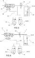
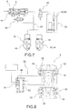
- FIGS. 1-8 show schematic views of braking systems according to a possible embodiment of the present invention.
- reference numeral 4 globally denotes a braking system for vehicles.
- vehicle should be understood in a non-limiting, manner, meaning preferably, but not exclusively, motor vehicles and/or vehicles.
- the braking system 4 comprises a manual actuator device 8, operable by means of a lever and/or pedal 12, operatively connected to at least a first braking device 16 acting on a brake disc or drum 18, so as to exert a braking action.
- the first braking device 16 is for example a caliper for a disc brake, acting on an associated brake disc, or a drum brake comprising one or more shoes acting on an associable drum, in a known manner.
- the manual actuator device 8 is a hydraulic pump, operable by means of the lever or pedal 12, operatively connected to the first braking device 16 by means of a hydraulic circuit 20 containing liquid pressurised by the hydraulic pump. It is also possible to provide for different operators of the first braking device 16, which are for example mechanical, electrical or electro/mechanical operators.
- the first manual actuator device may comprise not a hydraulic pump but a mechanical, electrical or electro/mechanical device operating the associable first braking device 16.
- the system 4 comprises an automatic actuator device 24, operatively connected to said manual actuator device 8 and/or to said first braking device 16, and at least a command panel 28 which supervises the operation of the braking system 4.
- the command panel 28 is operatively connected to the automatic actuator device 24 and is programmed so that when the manual actuator device 8 is operated, the panel 28 commands the operation of the automatic actuator device 24 so as to be able to:
- 'increasing' the overall braking action means that the braking system 4, under the supervision of the command panel 28, is able to increase the braking action of the first braking device 16 or the additional braking devices, compared to the braking action requested manually by the user through the operation of the lever or pedal 12.
- the increase of the braking action should be understood in a global sense as braking of the associable vehicle; it is therefore possible that the overall braking action is increased by operating for example a second braking device 34 not controlled by the manual actuator device 8, by means of the lever or pedal 12.
- the 'control' of the braking action of the brake system 4 is understood to mean that the command panel 28 is capable of limiting the overall braking action of the system, so as not to further operate the first braking device 16 or additional braking devices 32 of the system, despite the user's request for additional braking power from the system 4, using the lever or pedal 12 of the manual actuator device 8.
- a reduction of the overall braking action imposed by the manual actuator device 8 is taken to mean that the control unit is able to reduce the braking action acting on the first and/or second braking device in order to reduce the braking capacity, even counter to the braking request imposed by the user by means of the lever or pedal 12 of the manual actuator device 8.
- the command panel 28 is programmed to command the automatic actuator device 24 so as to operate the first braking device 16 simultaneously with the manual operation imposed by the manual actuator device 8 or by further braking devices 32 provided in said system, when, following the manual operation of the manual actuator device 8, no blocking phenomena of the brake disc or drum 18 occur.
- the command panel 28 is programmed to command the automatic actuator device 24 so as not to operate the first braking device 16 or further braking devices 32 provided in the system 4, when, following the manual operation of the manual actuator device 8, blocking phenomena of the brake disc or drum 18 occur.
- the command panel 28 is programmed to command the automatic actuator device 24 so as to directly contrast the action of the manual actuator device 8 opposing the thrust action of the lever or pedal 12, when, following the operation of the manual actuator device 8, blocking phenomena of the brake disc or drum 18 occur.
- the manual actuator device 8 is operatively connected to at least a first pusher of the first braking device 16 and the automatic actuator device 24 is operatively connected to at least a second pusher of the first braking device 16, said first and second pushers operating on the same brake disc or drum 18.
- Pusher is understood to mean a piston, in the case of the braking device 16, 32, 34 comprising a caliper disc brake or a brake shoe, in the case of the braking device 16, 32, 34 comprising a drum.
- the manual actuator device 8 is operatively connected to at least a first pusher of the first braking device 16 and the automatic actuator device 24 is operatively connected to at least a second pusher of a second braking device 34, said first and second pushers acting on separate brake discs or drums 18 mechanically connected in rotation to each other.
- Brake discs or drums 18 mechanically connected to each other in rotation is understood to mean that said brake discs or drums are associated to the same wheel or axle of the wheel so as to exert a concordant braking torque on said axle or wheel.
- the manual actuator device 8 is operatively connected to at least a first pusher of the first braking device 16 and the automatic actuator device is operatively connected to at least a second pusher of a second braking device 34, said first and second pushers operating on separate brake discs or drums 18 mechanically separate from each other and rotatably connected to different wheels of an associable vehicle.
- the command panel 28 is programmed to command the automatic actuator device 24 so as to operate the second braking device 34 so as to stabilise the vehicle, following the manual operation of the manual actuator device 8 acting on the first braking device 16.
- the automatic actuator device 24 comprises contrast means 40 acting in opposition to the thrust of the lever or pedal 12.
- said contrast means 40 act on the lever or pedal 12 so as to oppose the increase of the stroke of the lever or pedal imposed by the user or to reduce said stroke imposed by the user.
- the lever or pedal 12 pushes a piston 44 in an operating stroke or operating direction, the piston 44 being fluidically connected to a hydraulic operating circuit 20 of at least a first pusher of the first braking device 16, and wherein the contrast means 40, when operated, interrupt the fluidic connection between the piston 44 and the at least one first pusher.
- the interruption of said fluidic connection in fact prevents the user from being able to increase the braking action of the circuit.
- the lever or pedal 12 pushes a piston 44 fluidically connected to a hydraulic operating circuit 20 of at least a first pusher of the first braking device 16, and the contrast means 40, when operated, exert a thrust on the piston 44 in opposition to the operating direction.
- the contrast means 40 comprise a hydraulic device 42 which generates pressure acting on the piston 44 in opposition to the operating direction caused by the movement of the lever or pedal 12.
- the contrast means 40 comprise mechanical devices connected to the lever or pedal 12 or to kinematisms connected to the lever or pedal 12 so as to exercise a counter action such as to prevent the increase of the operating stroke or to reduce said stroke.
- said contrast means 40 are predisposed so as to exclude the manual operation of the braking devices 16, 32, 34 by the user, and to command the operation of the first braking device 16 or further braking devices 32, 34 of the system 4 so as to stabilise the dynamics of the associable vehicle, regardless of the manual operation of said pedal or lever 12 by the manual actuator device 8.
- the contrast means 40 are configured so as to exclude the hydraulic connection between the manual actuator device 8 and the braking devices 16, 32, 34, and to hydraulically connect the braking devices 16, 32, 34 exclusively to at least one automatic actuator device 24 so as to command the braking devices 16, 32, 34 for the dynamic stabilisation of the associable vehicle, preventing the manual operation of the braking devices.
- the contrast means can be configured as diverters which disconnect the braking devices 16, 32, 34 from the manual actuator device 8, and connect them to the automatic actuator device in order to permit the automatic operation of the braking devices to dynamically stabilize the vehicle regardless of the manual action exerted by the user on the lever or pedal 12.
- the braking system 4 comprises at least a second manual actuator device 52, operatively connected to the first manual actuator device 8 by means of an interposed braking balancing device 56, so as to be operated when the first manual actuator device 8 is operated, the second manual actuator device 52, operating at least a second braking device 34 acting on a drum brake disc 18 on a second axle of the associable vehicle, separate from a first vehicle axle on which the first braking device 16 acts, operated by the first manual actuator device 8.
- the automatic actuator device 24 by means of said command panel 28, commands the adjustment of the balancing device 56 so as to regulate and vary the operation of the second manual actuator device 52 in relation to the operation of the first manual actuator device 8. It is thus possible to modify the distribution of braking between the various braking devices 16, 34 acting on separate axles of the vehicle; this way one can modify for example the braking distribution between the front axle and the rear axle of a motor vehicle in order to customize the brake balance or optimize the stability control of the vehicle during the braking phase.
- the braking system according to the invention makes it possible to overcome the drawbacks of the prior art.
- the user always has the direct control of at least a portion of the hydraulic system connected to the braking devices, and consequently always has the sensation and direct control of said system or of at least a portion thereof, even when the system does not intervene to correct the braking request or to dynamically stabilise the vehicle.
Landscapes
- Engineering & Computer Science (AREA)
- Transportation (AREA)
- Mechanical Engineering (AREA)
- Physics & Mathematics (AREA)
- Fluid Mechanics (AREA)
- Regulating Braking Force (AREA)
- Braking Elements And Transmission Devices (AREA)
- Braking Systems And Boosters (AREA)
- Braking Arrangements (AREA)
- Electric Propulsion And Braking For Vehicles (AREA)
Claims (15)
- Bremssystem (4) für Fahrzeuge, umfassend:- eine manuelle Aktuatorvorrichtung (8), welche mittels eines Hebels und/oder Pedals (12) betätigbar ist, betriebsmäßig verbunden mit wenigstens einer ersten Bremsvorrichtung (16), welche auf eine Bremsscheibe oder -trommel (18) wirkt, um so eine Bremswirkung auszuüben,- eine automatische Aktuatorvorrichtung (24), welche betriebsmäßig mit der manuellen Aktuatorvorrichtung (8) und/oder der ersten Bremsvorrichtung (16) verbunden ist,- wenigstens ein Anweisungspaneel (28), welches die Funktion des Bremssystems (4) überwacht, wobei das Anweisungspaneel (28) betriebsmäßig mit der automatischen Aktuatorvorrichtung (24) verbunden und dazu programmiert ist, dass, wenn die manuelle Aktuatorvorrichtung (8) betätigt wird, das Anweisungspaneel (28) die Betätigung der automatischen Aktuatorvorrichtung (24) derart anweist, dass sie in der Lage ist:- eine Bremswirkung zu erzeugen oder die Gesamt-Bremswirkung des Bremssystems (4) zu erhöhen, wobei die Betätigung der ersten Bremsvorrichtung (16) oder weiterer in dem System bereitgestellter und auf weitere Bremsscheiben oder -trommeln wirkender Bremsvorrichtungen (32, 34) betätigt und/oder erhöht wird,- die Bremswirkung des Bremssystems (4) derart zu steuern/regeln, dass die erste Bremsvorrichtung (16) oder weitere Bremsvorrichtungen (32, 34) des Systems (4) nicht weiter betätigt werden,
dadurch gekennzeichnet, dass das Anweisungspaneel (28) ferner die Betätigung der automatischen Aktuatorvorrichtung (24) derart anweist, dass sie in der Lage ist:- die mittels der manuellen Aktuatorvorrichtung (8) eingewirkte Gesamt-Bremswirkung zu reduzieren, wobei die auf den Hebel und/oder das Pedal (12) eingewirkte Schubwirkung direkt gekontert wird. - Bremssystem (4) für Fahrzeuge nach Anspruch 1, wobei das Anweisungspaneel (28) dazu programmiert ist, die automatische Aktuatorvorrichtung (24) derart anzuweisen, dass sie die erste Bremsvorrichtung (16) gleichzeitig mit der durch die manuelle Aktuatorvorrichtung (8) oder durch weitere Bremsvorrichtungen (32, 34), welche in dem System vorgesehen sind, eingewirkten manuellen Betätigung betätigt, wenn der manuellen Betätigung der manuellen Aktuatorvorrichtung (8) folgend keine Blockierungsphänomene der Bremsscheibe oder -trommel (18) auftreten.
- Bremssystem (4) für Fahrzeuge nach Anspruch 1 oder 2, wobei das Anweisungspaneel (28) dazu programmiert ist, die automatische Aktuatorvorrichtung (24) dazu anzuweisen, die erste Bremsvorrichtung (16) oder weitere in dem System bereitgestellte Bremsvorrichtungen (32, 34) nicht zu betätigen, wenn der manuellen Betätigung der manuellen Aktuatorvorrichtung (8) folgend Blockierungsphänomene der Bremsscheibe oder -trommel (18) auftreten.
- Bremssystem (4) für Fahrzeuge nach Anspruch 1, 2 oder 3, wobei das Anweisungspaneel (28) dazu programmiert ist, die automatische Aktuatorvorrichtung (24) dazu anzuweisen, direkt der Wirkung der manuellen Aktuatorvorrichtung (8) entgegenzuwirken, gegenüber der Schubwirkung des Hebels oder Pedals (12), wenn der Betätigung der manuellen Aktuatorvorrichtung (8) folgend Blockierungsphänomene der Bremsscheibe oder -trommel (18) auftreten.
- Bremssystem (4) für Fahrzeuge nach einem der vorhergehenden Ansprüche, wobei das Anweisungspaneel (28) dazu programmiert ist, die automatische Aktuatorvorrichtung (24) dazu anzuweisen, eine Bremswirkung durch Betätigen der ersten Bremsvorrichtung (16) oder weiterer Bremsvorrichtungen (32, 34) des Systems (4) zu erzeugen, um so die Dynamiken des zuordenbaren Fahrzeugs zu stabilisieren, und die manuelle Betätigung der Bremsvorrichtungen (16, 32, 34) durch den Benutzer auszuschließen.
- Bremssystem (4) für Fahrzeuge nach einem der vorhergehenden Ansprüche, wobei die manuelle Aktuatorvorrichtung (8) betriebsmäßig mit wenigstens einem ersten Schieber der ersten Bremsvorrichtung (16) verbunden ist und die automatische Aktuatorvorrichtung (24) betriebsmäßig mit wenigstens einem zweiten Schieber der ersten Bremsvorrichtung (16) verbunden ist, wobei der erste und zweite Schieber auf dieselbe Bremsscheibe oder -trommel (18) einwirken.
- Bremssystem (4) für Fahrzeuge nach einem der vorhergehenden Ansprüche, wobei die manuelle Aktuatorvorrichtung (8) betriebsmäßig mit wenigstens einem ersten Schieber der ersten Bremsvorrichtung (16) verbunden ist und die automatische Aktuatorvorrichtung (24) betriebsmäßig mit wenigstens einem zweiten Schieber einer zweiten Bremsvorrichtung (32, 34) verbunden ist, wobei die ersten und zweiten Schieber auf unterschiedliche Bremsscheiben oder -trommeln (18) einwirken, welche mechanisch in Rotation miteinander verbunden sind.
- Bremssystem (4) für Fahrzeuge nach einem der vorhergehenden Ansprüche, wobei die manuelle Aktuatorvorrichtung (8) betriebsmäßig mit wenigstens einem ersten Schieber der ersten Bremsvorrichtung (16) verbunden ist und die automatische Aktuatorvorrichtung (24) betriebsmäßig mit wenigstens einem zweiten Schieber einer zweiten Bremsvorrichtung (32, 34) verbunden ist, wobei der erste und zweite Schieber auf unterschiedliche Bremsscheiben oder -trommeln (18) einwirken, welche mechanisch separat voneinander und verbunden sind, um an unterschiedlichen Rädern eines zuordenbaren Fahrzeugs zu rotieren.
- Bremssystem (4) für Fahrzeuge nach einem der vorhergehenden Ansprüche, wobei die automatische Aktuatorvorrichtung (24) Gegenwirkungs-Mittel (40) umfasst, welche entgegen dem Schub des Hebels oder Pedals (12) wirken.
- Bremssystem (4) für Fahrzeuge nach Anspruch 9, wobei der Hebel oder das Pedal (12) einen Kolben (44) schiebt, welcher fluidisch mit einem Hydraulik-Betriebskreislauf (20) von wenigstens einem ersten Schieber der ersten Bremsvorrichtung (16) verbunden ist, und wobei die Gegenwirkungs-Mittel (40), wenn sie betätigt werden, die Fluidverbindung zwischen dem Kolben (44) und dem wenigstens einen ersten Schieber unterbrechen.
- Bremssystem (4) für Fahrzeuge nach Anspruch 9 oder 10, wobei der Hebel oder das Pedal (12) einen Kolben (44) schiebt, welcher fluidisch mit einem Hydraulik-Betriebskreislauf (20) von wenigstens einem ersten Schieber der ersten Bremsvorrichtung (16) verbunden ist, und wobei die Gegenwirkungs-Mittel (40), wenn sie betätigt werden, einen Schub auf den Kolben (44) entgegen dem Betätigungshub und der Betätigungsrichtung ausüben.
- Bremssystem (4) für Fahrzeuge nach einem der Ansprüche 9 bis 11, wobei die Gegenwirkungs-Mittel (40) dazu voreingerichtet sind, die manuelle Betätigung der Bremsvorrichtungen (16, 32, 34) durch den Benutzer auszuschließen und die Betätigung der ersten Bremsvorrichtung (16) oder weiterer Bremsvorrichtungen (32, 34) des Systems (4) anzuweisen, um so die Dynamiken des zuordenbaren Fahrzeugs zu stabilisieren, ungeachtet der manuellen Wirkung der manuellen Aktuatorvorrichtung (8) auf das Pedal oder den Hebel (12).
- Bremssystem (4) für Fahrzeuge nach einem der Ansprüche 9 bis 12, wobei die Gegenwirkungs-Mittel (40) dazu eingerichtet sind, die hydraulische Verbindung zwischen der Aktuatorvorrichtung (8) und den Bremsvorrichtungen (16, 32, 34) auszuschließen und die Bremsvorrichtungen (16, 32, 34) hydraulisch ausschließlich mit wenigstens einer automatischen Aktuatorvorrichtung (24) zu verbinden, um so die Bremsvorrichtungen (16, 32, 34) für die dynamische Stabilisierung des zuordenbaren Fahrzeugs anzuweisen, wobei die manuelle Betätigung der Bremsvorrichtungen verhindert wird.
- Bremssystem nach einem der vorhergehenden Ansprüche, umfassend:- eine manuelle Aktuatorvorrichtung (8), welche mittels eines Hebels und/oder Pedals (12) betätigbar ist, betriebsmäßig mit wenigstens einer ersten Bremsvorrichtung (16) verbunden, welche auf eine Bremsscheibe oder -trommel (18) an einer ersten Achse eines zuordenbaren Fahrzeugs wirkt, um so eine Bremswirkung auszuüben,- eine automatische Aktuatorvorrichtung (24), welche betriebsmäßig mit der manuellen Aktuatorvorrichtung (8) und/oder der ersten Bremsvorrichtung (16) verbunden ist,- wenigstens ein Anweisungspaneel (28), welches die Funktion des Bremssystems (4) überwacht, wobei das Anweisungspaneel (28) betriebsmäßig mit der automatischen Aktuatorvorrichtung (24) verbunden und dazu programmiert ist, dass, wenn die manuelle Aktuatorvorrichtung (8) betätigt wird, das Paneel (28) die Betätigung der automatischen Aktuatorvorrichtung (24) derart anweist, dass sie in der Lage ist:- die Gesamt-Bremswirkung des Bremssystems (4) zu erhöhen, wobei ferner die erste Bremsvorrichtung (16) oder weitere in dem System bereitgestellte und auf weitere Bremsscheiben oder -trommeln (18) wirkende Bremsvorrichtungen (32, 34) betätigt werden,- Steuern/Regeln der Bremswirkung des Bremssystems (4) derart, dass die erste Bremsvorrichtung (16) oder die weiteren Bremsvorrichtungen (32, 34) des Systems nicht weiter betätigt werden,- die mittels der manuellen Aktuatorvorrichtung (8) eingewirkte Gesamt-Bremswirkung zu reduzieren, wobei die auf den Hebel und/oder das Pedal (12) eingewirkte Schubwirkung direkt gekontert wird,- wenigstens eine zweite manuelle Aktuatorvorrichtung (52), welche betriebsmäßig mit der ersten manuellen Aktuatorvorrichtung (8) mittels einer eingefügten Ausgleichsvorrichtung (56) der Bremse verbunden ist, um betätigt zu werden, wenn die erste manuelle Aktuatorvorrichtung (8) betätigt wird, wobei die zweite manuelle Aktuatorvorrichtung (52) wenigstens eine zweite Bremsvorrichtung (32, 34) betätigt, welche auf eine Trommel-Bremsscheibe (18) an einer zweiten Achse des zuordenbaren Fahrzeugs wirkt, separat von einer ersten Fahrzeugachse, auf welche die erste Bremsvorrichtung (16) wirkt, betätigt von der ersten manuellen Aktuatorvorrichtung (8),- wobei die automatische Aktuatorvorrichtung (24) mittels des Steuerpaneels (28) die Anpassung der Ausgleichsvorrichtung (56) anweist, um so den Betrieb der zweiten manuellen Aktuatorvorrichtung (52) bezüglich der ersten manuellen Aktuatorvorrichtung (8) zu regulieren und variieren.
- Verfahren zum Steuern/Regeln eines Bremssystems (4) für Fahrzeuge, umfassend die Schritte:- Bereitstellen einer manuellen Aktuatorvorrichtung (8), welche mittels eines Hebels und/oder eines Pedals (12) betätigbar ist, betriebsmäßig verbunden mit wenigstens einer ersten Bremsvorrichtung (16), welche auf eine Bremsscheibe oder -trommel (18) wirkt, um so eine Bremswirkung auszuüben,- Bereitstellen einer automatischen Aktuatorvorrichtung (24), welche betriebsmäßig mit der manuellen Aktuatorvorrichtung (8) und/oder der ersten Bremsvorrichtung (16) verbunden ist,- Bereitstellen wenigstens eines Anweisungspaneels (28), welches die Funktion des Bremssystems überwacht, wobei das Anweisungspaneel (28) betriebsmäßig mit der automatischen Aktuatorvorrichtung (24) verbunden ist,- wobei, wenn die manuelle Aktuatorvorrichtung (8) betätigt wird, das Paneel (28) den Betrieb der automatischen Aktuatorvorrichtung (24) anweist, um in der Lage zu sein:- die Gesamt-Bremswirkung des Bremssystems zu erhöhen, wobei ferner die erste Bremsvorrichtung (16) oder weitere in dem System bereitgestellte und auf weitere Bremsscheiben oder -trommeln (18) wirkende Bremsvorrichtungen (32, 34) betätigt werden,- die Bremswirkung des Bremssystems zu steuern/regeln, um so die erste Bremsvorrichtung (16) oder weitere Bremsvorrichtungen (32, 34) des Systems nicht weiter zu betätigen,- die mittels der manuellen Aktuatorvorrichtung (8) eingewirkte Gesamt-Bremswirkung zu reduzieren, wobei die auf den Hebel und/oder das Pedal (12) ausgeübte Schubwirkung direkt gekontert wird.
Applications Claiming Priority (2)
| Application Number | Priority Date | Filing Date | Title |
|---|---|---|---|
| IT001049A ITTO20131049A1 (it) | 2013-12-19 | 2013-12-19 | Impianto frenante a controllo automatico |
| PCT/IB2014/067002 WO2015092700A2 (en) | 2013-12-19 | 2014-12-17 | Automatically controlled braking system |
Publications (2)
| Publication Number | Publication Date |
|---|---|
| EP3083349A2 EP3083349A2 (de) | 2016-10-26 |
| EP3083349B1 true EP3083349B1 (de) | 2018-03-14 |
Family
ID=50159437
Family Applications (1)
| Application Number | Title | Priority Date | Filing Date |
|---|---|---|---|
| EP14830688.9A Active EP3083349B1 (de) | 2013-12-19 | 2014-12-17 | Automatisch gesteuertes bremssystem |
Country Status (4)
| Country | Link |
|---|---|
| US (1) | US11724675B2 (de) |
| EP (1) | EP3083349B1 (de) |
| IT (1) | ITTO20131049A1 (de) |
| WO (1) | WO2015092700A2 (de) |
Families Citing this family (2)
| Publication number | Priority date | Publication date | Assignee | Title |
|---|---|---|---|---|
| ES2964118T3 (es) * | 2018-09-19 | 2024-04-04 | Brembo Spa | Sistema de frenado de freno por cable eléctrico controlado de manera automática para motocicletas |
| TWI707795B (zh) * | 2019-07-10 | 2020-10-21 | 彥豪金屬工業股份有限公司 | 自行車卡鉗、自行車卡鉗控制系統及自行車卡鉗控制方法 |
Family Cites Families (8)
| Publication number | Priority date | Publication date | Assignee | Title |
|---|---|---|---|---|
| FR2559112B1 (fr) * | 1984-02-06 | 1986-12-26 | Renault | Circuit hydraulique a piston pour prevenir le blocage des freins d'un vehicule |
| US5152588A (en) * | 1991-06-28 | 1992-10-06 | General Motors Corporation | Anti-lock braking system |
| JP2002321611A (ja) * | 2001-04-26 | 2002-11-05 | Bosch Braking Systems Co Ltd | 電動式ブレーキ倍力装置 |
| EP1674360B1 (de) * | 2004-12-24 | 2012-01-18 | Honda Motor Co., Ltd. | Fahrzeugbremsvorrichtung und diesbezügliches Regelungsverfahren |
| DE102007016864B4 (de) * | 2007-04-10 | 2024-11-14 | Robert Bosch Gmbh | Bremssystem für ein Fahrzeug |
| JP5150919B2 (ja) * | 2008-02-27 | 2013-02-27 | 本田技研工業株式会社 | 車両のブレーキ装置 |
| DE102012222058B4 (de) * | 2012-12-03 | 2024-03-21 | Robert Bosch Gmbh | Hydraulisches Bremssystem für Zweiräder |
| ITUB20152710A1 (it) * | 2015-07-31 | 2017-01-31 | Freni Brembo Spa | Impianto frenante per veicoli, in particolare cicli e motocicli, e metodo di attuazione di un impianto frenante per veicoli |
-
2013
- 2013-12-19 IT IT001049A patent/ITTO20131049A1/it unknown
-
2014
- 2014-12-17 WO PCT/IB2014/067002 patent/WO2015092700A2/en not_active Ceased
- 2014-12-17 EP EP14830688.9A patent/EP3083349B1/de active Active
- 2014-12-17 US US14/999,726 patent/US11724675B2/en active Active
Also Published As
| Publication number | Publication date |
|---|---|
| WO2015092700A2 (en) | 2015-06-25 |
| US11724675B2 (en) | 2023-08-15 |
| ITTO20131049A1 (it) | 2015-06-20 |
| WO2015092700A3 (en) | 2015-11-12 |
| US20160355166A1 (en) | 2016-12-08 |
| EP3083349A2 (de) | 2016-10-26 |
Similar Documents
| Publication | Publication Date | Title |
|---|---|---|
| EP3386812B1 (de) | Brake-by-wire -fahrzeugbremssystem, mit hydraulischem feedbacksimulator, und -betriebsverfahren | |
| CN113165610B (zh) | 用于机动车的自动控制线控制动的制动系统 | |
| KR102286836B1 (ko) | 차량용 제동 장치 | |
| JP6756920B2 (ja) | 車両制動システム及び方法 | |
| CN100581886C (zh) | 具有电子制动控制装置和预填充功能的制动系统和电子制动控制方法 | |
| EP3630559B1 (de) | Bremssystem für brake-by-wire-fahrzeuge mit hydraulischem feedback-simulator und betätigungsverfahren eines bremssystems für fahrzeuge | |
| JP2018538190A5 (de) | ||
| US20170137009A1 (en) | Automatically controlled braking system for vehicles and method of actuating and controlling a braking system for vehicles | |
| EP3178712B1 (de) | Brake-by-wire-bremssystem für fahrzeuge mit hydraulischem simulator und betätigungssverfahren | |
| EP3083349B1 (de) | Automatisch gesteuertes bremssystem | |
| EP3009314B1 (de) | Automatisch gesteuertes bremssystem für fahrzeuge und entsprechende methode zum betrieb eines solchen systems | |
| US20180312145A1 (en) | Automatically Controlled Actuator Device For Brakes | |
| EP4267438B1 (de) | Integral-brake-by-wire-bremssystem für motorräder und zugehöriges motorrad | |
| EP3445624B1 (de) | Automatisiertes gesteuertes bremssystem für fahrzeuge |
Legal Events
| Date | Code | Title | Description |
|---|---|---|---|
| PUAI | Public reference made under article 153(3) epc to a published international application that has entered the european phase |
Free format text: ORIGINAL CODE: 0009012 |
|
| 17P | Request for examination filed |
Effective date: 20160613 |
|
| AK | Designated contracting states |
Kind code of ref document: A2 Designated state(s): AL AT BE BG CH CY CZ DE DK EE ES FI FR GB GR HR HU IE IS IT LI LT LU LV MC MK MT NL NO PL PT RO RS SE SI SK SM TR |
|
| AX | Request for extension of the european patent |
Extension state: BA ME |
|
| DAX | Request for extension of the european patent (deleted) | ||
| GRAP | Despatch of communication of intention to grant a patent |
Free format text: ORIGINAL CODE: EPIDOSNIGR1 |
|
| INTG | Intention to grant announced |
Effective date: 20171002 |
|
| GRAS | Grant fee paid |
Free format text: ORIGINAL CODE: EPIDOSNIGR3 |
|
| GRAA | (expected) grant |
Free format text: ORIGINAL CODE: 0009210 |
|
| AK | Designated contracting states |
Kind code of ref document: B1 Designated state(s): AL AT BE BG CH CY CZ DE DK EE ES FI FR GB GR HR HU IE IS IT LI LT LU LV MC MK MT NL NO PL PT RO RS SE SI SK SM TR |
|
| REG | Reference to a national code |
Ref country code: GB Ref legal event code: FG4D |
|
| REG | Reference to a national code |
Ref country code: CH Ref legal event code: EP Ref country code: AT Ref legal event code: REF Ref document number: 978561 Country of ref document: AT Kind code of ref document: T Effective date: 20180315 |
|
| REG | Reference to a national code |
Ref country code: IE Ref legal event code: FG4D |
|
| REG | Reference to a national code |
Ref country code: DE Ref legal event code: R096 Ref document number: 602014022435 Country of ref document: DE |
|
| REG | Reference to a national code |
Ref country code: NL Ref legal event code: MP Effective date: 20180314 |
|
| REG | Reference to a national code |
Ref country code: LT Ref legal event code: MG4D |
|
| PG25 | Lapsed in a contracting state [announced via postgrant information from national office to epo] |
Ref country code: CY Free format text: LAPSE BECAUSE OF FAILURE TO SUBMIT A TRANSLATION OF THE DESCRIPTION OR TO PAY THE FEE WITHIN THE PRESCRIBED TIME-LIMIT Effective date: 20180314 Ref country code: HR Free format text: LAPSE BECAUSE OF FAILURE TO SUBMIT A TRANSLATION OF THE DESCRIPTION OR TO PAY THE FEE WITHIN THE PRESCRIBED TIME-LIMIT Effective date: 20180314 Ref country code: LT Free format text: LAPSE BECAUSE OF FAILURE TO SUBMIT A TRANSLATION OF THE DESCRIPTION OR TO PAY THE FEE WITHIN THE PRESCRIBED TIME-LIMIT Effective date: 20180314 Ref country code: NO Free format text: LAPSE BECAUSE OF FAILURE TO SUBMIT A TRANSLATION OF THE DESCRIPTION OR TO PAY THE FEE WITHIN THE PRESCRIBED TIME-LIMIT Effective date: 20180614 Ref country code: FI Free format text: LAPSE BECAUSE OF FAILURE TO SUBMIT A TRANSLATION OF THE DESCRIPTION OR TO PAY THE FEE WITHIN THE PRESCRIBED TIME-LIMIT Effective date: 20180314 |
|
| REG | Reference to a national code |
Ref country code: AT Ref legal event code: MK05 Ref document number: 978561 Country of ref document: AT Kind code of ref document: T Effective date: 20180314 |
|
| PG25 | Lapsed in a contracting state [announced via postgrant information from national office to epo] |
Ref country code: SE Free format text: LAPSE BECAUSE OF FAILURE TO SUBMIT A TRANSLATION OF THE DESCRIPTION OR TO PAY THE FEE WITHIN THE PRESCRIBED TIME-LIMIT Effective date: 20180314 Ref country code: LV Free format text: LAPSE BECAUSE OF FAILURE TO SUBMIT A TRANSLATION OF THE DESCRIPTION OR TO PAY THE FEE WITHIN THE PRESCRIBED TIME-LIMIT Effective date: 20180314 Ref country code: BG Free format text: LAPSE BECAUSE OF FAILURE TO SUBMIT A TRANSLATION OF THE DESCRIPTION OR TO PAY THE FEE WITHIN THE PRESCRIBED TIME-LIMIT Effective date: 20180614 Ref country code: GR Free format text: LAPSE BECAUSE OF FAILURE TO SUBMIT A TRANSLATION OF THE DESCRIPTION OR TO PAY THE FEE WITHIN THE PRESCRIBED TIME-LIMIT Effective date: 20180615 Ref country code: RS Free format text: LAPSE BECAUSE OF FAILURE TO SUBMIT A TRANSLATION OF THE DESCRIPTION OR TO PAY THE FEE WITHIN THE PRESCRIBED TIME-LIMIT Effective date: 20180314 |
|
| PG25 | Lapsed in a contracting state [announced via postgrant information from national office to epo] |
Ref country code: AL Free format text: LAPSE BECAUSE OF FAILURE TO SUBMIT A TRANSLATION OF THE DESCRIPTION OR TO PAY THE FEE WITHIN THE PRESCRIBED TIME-LIMIT Effective date: 20180314 Ref country code: ES Free format text: LAPSE BECAUSE OF FAILURE TO SUBMIT A TRANSLATION OF THE DESCRIPTION OR TO PAY THE FEE WITHIN THE PRESCRIBED TIME-LIMIT Effective date: 20180314 Ref country code: PL Free format text: LAPSE BECAUSE OF FAILURE TO SUBMIT A TRANSLATION OF THE DESCRIPTION OR TO PAY THE FEE WITHIN THE PRESCRIBED TIME-LIMIT Effective date: 20180314 Ref country code: NL Free format text: LAPSE BECAUSE OF FAILURE TO SUBMIT A TRANSLATION OF THE DESCRIPTION OR TO PAY THE FEE WITHIN THE PRESCRIBED TIME-LIMIT Effective date: 20180314 Ref country code: RO Free format text: LAPSE BECAUSE OF FAILURE TO SUBMIT A TRANSLATION OF THE DESCRIPTION OR TO PAY THE FEE WITHIN THE PRESCRIBED TIME-LIMIT Effective date: 20180314 Ref country code: IT Free format text: LAPSE BECAUSE OF FAILURE TO SUBMIT A TRANSLATION OF THE DESCRIPTION OR TO PAY THE FEE WITHIN THE PRESCRIBED TIME-LIMIT Effective date: 20180314 Ref country code: EE Free format text: LAPSE BECAUSE OF FAILURE TO SUBMIT A TRANSLATION OF THE DESCRIPTION OR TO PAY THE FEE WITHIN THE PRESCRIBED TIME-LIMIT Effective date: 20180314 |
|
| PG25 | Lapsed in a contracting state [announced via postgrant information from national office to epo] |
Ref country code: SM Free format text: LAPSE BECAUSE OF FAILURE TO SUBMIT A TRANSLATION OF THE DESCRIPTION OR TO PAY THE FEE WITHIN THE PRESCRIBED TIME-LIMIT Effective date: 20180314 Ref country code: AT Free format text: LAPSE BECAUSE OF FAILURE TO SUBMIT A TRANSLATION OF THE DESCRIPTION OR TO PAY THE FEE WITHIN THE PRESCRIBED TIME-LIMIT Effective date: 20180314 Ref country code: CZ Free format text: LAPSE BECAUSE OF FAILURE TO SUBMIT A TRANSLATION OF THE DESCRIPTION OR TO PAY THE FEE WITHIN THE PRESCRIBED TIME-LIMIT Effective date: 20180314 Ref country code: SK Free format text: LAPSE BECAUSE OF FAILURE TO SUBMIT A TRANSLATION OF THE DESCRIPTION OR TO PAY THE FEE WITHIN THE PRESCRIBED TIME-LIMIT Effective date: 20180314 |
|
| REG | Reference to a national code |
Ref country code: DE Ref legal event code: R097 Ref document number: 602014022435 Country of ref document: DE |
|
| PG25 | Lapsed in a contracting state [announced via postgrant information from national office to epo] |
Ref country code: PT Free format text: LAPSE BECAUSE OF FAILURE TO SUBMIT A TRANSLATION OF THE DESCRIPTION OR TO PAY THE FEE WITHIN THE PRESCRIBED TIME-LIMIT Effective date: 20180716 |
|
| PLBE | No opposition filed within time limit |
Free format text: ORIGINAL CODE: 0009261 |
|
| STAA | Information on the status of an ep patent application or granted ep patent |
Free format text: STATUS: NO OPPOSITION FILED WITHIN TIME LIMIT |
|
| PG25 | Lapsed in a contracting state [announced via postgrant information from national office to epo] |
Ref country code: DK Free format text: LAPSE BECAUSE OF FAILURE TO SUBMIT A TRANSLATION OF THE DESCRIPTION OR TO PAY THE FEE WITHIN THE PRESCRIBED TIME-LIMIT Effective date: 20180314 |
|
| 26N | No opposition filed |
Effective date: 20181217 |
|
| PG25 | Lapsed in a contracting state [announced via postgrant information from national office to epo] |
Ref country code: SI Free format text: LAPSE BECAUSE OF FAILURE TO SUBMIT A TRANSLATION OF THE DESCRIPTION OR TO PAY THE FEE WITHIN THE PRESCRIBED TIME-LIMIT Effective date: 20180314 |
|
| REG | Reference to a national code |
Ref country code: CH Ref legal event code: PL |
|
| PG25 | Lapsed in a contracting state [announced via postgrant information from national office to epo] |
Ref country code: MC Free format text: LAPSE BECAUSE OF FAILURE TO SUBMIT A TRANSLATION OF THE DESCRIPTION OR TO PAY THE FEE WITHIN THE PRESCRIBED TIME-LIMIT Effective date: 20180314 Ref country code: LU Free format text: LAPSE BECAUSE OF NON-PAYMENT OF DUE FEES Effective date: 20181217 |
|
| REG | Reference to a national code |
Ref country code: IE Ref legal event code: MM4A |
|
| REG | Reference to a national code |
Ref country code: BE Ref legal event code: MM Effective date: 20181231 |
|
| PG25 | Lapsed in a contracting state [announced via postgrant information from national office to epo] |
Ref country code: FR Free format text: LAPSE BECAUSE OF NON-PAYMENT OF DUE FEES Effective date: 20181231 Ref country code: IE Free format text: LAPSE BECAUSE OF NON-PAYMENT OF DUE FEES Effective date: 20181217 |
|
| PG25 | Lapsed in a contracting state [announced via postgrant information from national office to epo] |
Ref country code: BE Free format text: LAPSE BECAUSE OF NON-PAYMENT OF DUE FEES Effective date: 20181231 |
|
| PG25 | Lapsed in a contracting state [announced via postgrant information from national office to epo] |
Ref country code: LI Free format text: LAPSE BECAUSE OF NON-PAYMENT OF DUE FEES Effective date: 20181231 Ref country code: CH Free format text: LAPSE BECAUSE OF NON-PAYMENT OF DUE FEES Effective date: 20181231 |
|
| PG25 | Lapsed in a contracting state [announced via postgrant information from national office to epo] |
Ref country code: MT Free format text: LAPSE BECAUSE OF NON-PAYMENT OF DUE FEES Effective date: 20181217 |
|
| PG25 | Lapsed in a contracting state [announced via postgrant information from national office to epo] |
Ref country code: TR Free format text: LAPSE BECAUSE OF FAILURE TO SUBMIT A TRANSLATION OF THE DESCRIPTION OR TO PAY THE FEE WITHIN THE PRESCRIBED TIME-LIMIT Effective date: 20180314 |
|
| PG25 | Lapsed in a contracting state [announced via postgrant information from national office to epo] |
Ref country code: MK Free format text: LAPSE BECAUSE OF NON-PAYMENT OF DUE FEES Effective date: 20180314 Ref country code: HU Free format text: LAPSE BECAUSE OF FAILURE TO SUBMIT A TRANSLATION OF THE DESCRIPTION OR TO PAY THE FEE WITHIN THE PRESCRIBED TIME-LIMIT; INVALID AB INITIO Effective date: 20141217 |
|
| PG25 | Lapsed in a contracting state [announced via postgrant information from national office to epo] |
Ref country code: IS Free format text: LAPSE BECAUSE OF FAILURE TO SUBMIT A TRANSLATION OF THE DESCRIPTION OR TO PAY THE FEE WITHIN THE PRESCRIBED TIME-LIMIT Effective date: 20180714 |
|
| REG | Reference to a national code |
Ref country code: DE Ref legal event code: R081 Ref document number: 602014022435 Country of ref document: DE Owner name: BREMBO S.P.A., CURNO, IT Free format text: FORMER OWNER: FRENI BREMBO S.P.A., CURNO, BERGAMO, IT |
|
| P01 | Opt-out of the competence of the unified patent court (upc) registered |
Effective date: 20230526 |
|
| PGFP | Annual fee paid to national office [announced via postgrant information from national office to epo] |
Ref country code: GB Payment date: 20251219 Year of fee payment: 12 |
|
| PGFP | Annual fee paid to national office [announced via postgrant information from national office to epo] |
Ref country code: DE Payment date: 20251222 Year of fee payment: 12 |