EP3082331A1 - Sensor mit gehäuse - Google Patents
Sensor mit gehäuse Download PDFInfo
- Publication number
- EP3082331A1 EP3082331A1 EP16161530.7A EP16161530A EP3082331A1 EP 3082331 A1 EP3082331 A1 EP 3082331A1 EP 16161530 A EP16161530 A EP 16161530A EP 3082331 A1 EP3082331 A1 EP 3082331A1
- Authority
- EP
- European Patent Office
- Prior art keywords
- holder
- sensor
- receptacle
- housing
- reference surface
- Prior art date
- Legal status (The legal status is an assumption and is not a legal conclusion. Google has not performed a legal analysis and makes no representation as to the accuracy of the status listed.)
- Granted
Links
Images




Classifications
-
- G—PHYSICS
- G01—MEASURING; TESTING
- G01D—MEASURING NOT SPECIALLY ADAPTED FOR A SPECIFIC VARIABLE; ARRANGEMENTS FOR MEASURING TWO OR MORE VARIABLES NOT COVERED IN A SINGLE OTHER SUBCLASS; TARIFF METERING APPARATUS; MEASURING OR TESTING NOT OTHERWISE PROVIDED FOR
- G01D11/00—Component parts of measuring arrangements not specially adapted for a specific variable
- G01D11/30—Supports specially adapted for an instrument; Supports specially adapted for a set of instruments
-
- F—MECHANICAL ENGINEERING; LIGHTING; HEATING; WEAPONS; BLASTING
- F16—ENGINEERING ELEMENTS AND UNITS; GENERAL MEASURES FOR PRODUCING AND MAINTAINING EFFECTIVE FUNCTIONING OF MACHINES OR INSTALLATIONS; THERMAL INSULATION IN GENERAL
- F16M—FRAMES, CASINGS OR BEDS OF ENGINES, MACHINES OR APPARATUS, NOT SPECIFIC TO ENGINES, MACHINES OR APPARATUS PROVIDED FOR ELSEWHERE; STANDS; SUPPORTS
- F16M11/00—Stands or trestles as supports for apparatus or articles placed thereon ; Stands for scientific apparatus such as gravitational force meters
- F16M11/02—Heads
- F16M11/04—Means for attachment of apparatus; Means allowing adjustment of the apparatus relatively to the stand
- F16M11/041—Allowing quick release of the apparatus
-
- F—MECHANICAL ENGINEERING; LIGHTING; HEATING; WEAPONS; BLASTING
- F16—ENGINEERING ELEMENTS AND UNITS; GENERAL MEASURES FOR PRODUCING AND MAINTAINING EFFECTIVE FUNCTIONING OF MACHINES OR INSTALLATIONS; THERMAL INSULATION IN GENERAL
- F16M—FRAMES, CASINGS OR BEDS OF ENGINES, MACHINES OR APPARATUS, NOT SPECIFIC TO ENGINES, MACHINES OR APPARATUS PROVIDED FOR ELSEWHERE; STANDS; SUPPORTS
- F16M11/00—Stands or trestles as supports for apparatus or articles placed thereon ; Stands for scientific apparatus such as gravitational force meters
- F16M11/02—Heads
- F16M11/04—Means for attachment of apparatus; Means allowing adjustment of the apparatus relatively to the stand
- F16M11/06—Means for attachment of apparatus; Means allowing adjustment of the apparatus relatively to the stand allowing pivoting
- F16M11/10—Means for attachment of apparatus; Means allowing adjustment of the apparatus relatively to the stand allowing pivoting around a horizontal axis
-
- F—MECHANICAL ENGINEERING; LIGHTING; HEATING; WEAPONS; BLASTING
- F16—ENGINEERING ELEMENTS AND UNITS; GENERAL MEASURES FOR PRODUCING AND MAINTAINING EFFECTIVE FUNCTIONING OF MACHINES OR INSTALLATIONS; THERMAL INSULATION IN GENERAL
- F16M—FRAMES, CASINGS OR BEDS OF ENGINES, MACHINES OR APPARATUS, NOT SPECIFIC TO ENGINES, MACHINES OR APPARATUS PROVIDED FOR ELSEWHERE; STANDS; SUPPORTS
- F16M11/00—Stands or trestles as supports for apparatus or articles placed thereon ; Stands for scientific apparatus such as gravitational force meters
- F16M11/20—Undercarriages with or without wheels
- F16M11/2007—Undercarriages with or without wheels comprising means allowing pivoting adjustment
- F16M11/2014—Undercarriages with or without wheels comprising means allowing pivoting adjustment around a vertical axis
-
- H—ELECTRICITY
- H04—ELECTRIC COMMUNICATION TECHNIQUE
- H04N—PICTORIAL COMMUNICATION, e.g. TELEVISION
- H04N23/00—Cameras or camera modules comprising electronic image sensors; Control thereof
- H04N23/50—Constructional details
- H04N23/51—Housings
-
- G—PHYSICS
- G03—PHOTOGRAPHY; CINEMATOGRAPHY; ANALOGOUS TECHNIQUES USING WAVES OTHER THAN OPTICAL WAVES; ELECTROGRAPHY; HOLOGRAPHY
- G03B—APPARATUS OR ARRANGEMENTS FOR TAKING PHOTOGRAPHS OR FOR PROJECTING OR VIEWING THEM; APPARATUS OR ARRANGEMENTS EMPLOYING ANALOGOUS TECHNIQUES USING WAVES OTHER THAN OPTICAL WAVES; ACCESSORIES THEREFOR
- G03B17/00—Details of cameras or camera bodies; Accessories therefor
- G03B17/28—Locating light-sensitive material within camera
-
- G—PHYSICS
- G03—PHOTOGRAPHY; CINEMATOGRAPHY; ANALOGOUS TECHNIQUES USING WAVES OTHER THAN OPTICAL WAVES; ELECTROGRAPHY; HOLOGRAPHY
- G03B—APPARATUS OR ARRANGEMENTS FOR TAKING PHOTOGRAPHS OR FOR PROJECTING OR VIEWING THEM; APPARATUS OR ARRANGEMENTS EMPLOYING ANALOGOUS TECHNIQUES USING WAVES OTHER THAN OPTICAL WAVES; ACCESSORIES THEREFOR
- G03B2217/00—Details of cameras or camera bodies; Accessories therefor
- G03B2217/002—Details of arrangement of components in or on camera body
Definitions
- the present invention relates to a mounting unit for a sensor.
- the DE 10 2013 104 974 A1 discloses a fastening unit for attaching a sensor to an object, wherein the fastening unit has fastening means by means of which the fastening unit is fastened to the object and wherein the fastening unit has a dovetail guide in which a slide present on the sensor can be stored, whereby the sensor on the Fixing unit is attached, wherein the fastening unit has two extending in different planes reference surfaces which are provided fixed to the fixing unit.
- position pins are often used, as in the EP 1 533 998 B1 described.
- An object of the invention is to ensure a secure, accurate and accurate attachment of the sensor to a holder. Next, a reproducible attachment to a sensor replacement is to be made possible. Next, an exchange of the sensor should be easily possible.
- a sensor having a housing, wherein the housing has a receptacle for a holder, wherein the receptacle has at least one first reference surface and at least one second reference surface, wherein the holder in each case at least one corresponding first reference surface and at least one second reference surface, wherein the receptacle of the housing has at least one fastening screw and the fastening screw is arranged opposite to the second reference surface on the receptacle and at a fastening by the fastening screw, the first reference surfaces and the second reference surfaces abut each other.
- the reference surfaces ensure accurate positioning of the sensor. Furthermore, a good reproducibility of the sensor position during a sensor replacement is ensured since the replacement sensor only needs to be exactly aligned again with the reference surfaces of the holder, whereby exactly the same position of the exchange sensor is achieved, as the original position of the sensor.
- the fastening screw abuts a mounting surface of the holder.
- the attachment surface is arranged opposite the second reference surface on the holder.
- the attachment surface may be arranged and formed mirror-symmetrically to the second reference surface.
- the fastening screw has a conical screw tip.
- the surface of the conical screw tip abuts when attached to the mounting surface of the holder.
- the fastening screws are optionally accessible from one side of the housing, at which the receiving light enters the housing, ie from the 'viewing direction side' of the sensor.
- the sensor has, for example, a windscreen on this side. As a result, an installation and removal of the sensor is also possible if the sensor is installed all around.
- the receptacle is integrally formed or connected to the housing.
- the receptacle is integrated into the housing.
- the housing and the receptacle are made of the same material.
- the reference surfaces of the images are always automatically aligned correctly with the housing and have the same reference.
- two identical receptacles are arranged at a distance from the housing and two corresponding identical holders are arranged at an identical distance.
- first reference surfaces and the second reference surfaces are arranged in different planes. This ensures a reference position in two different directions.
- the first reference surfaces and the second reference surfaces are arranged at an acute angle to each other. This ensures, on the one hand, a reference position in two different directions. Further, a wedge shape is formed by the acute angle, whereby the holder is stably fixed between the two reference surfaces. By arranged at an acute angle reference surfaces of the holder is inevitably guided mechanically in the correct position, whereby a simple positioning is achieved.
- the fastening screw is a grub screw.
- a grub screw has a continuous thread, wherein the screw head has an identical diameter as the thread and is also surrounded by the thread.
- a third reference surface is arranged perpendicular to the first reference surface and perpendicular to the second reference surface. This ensures a reference position in three different directions. As a result, the sensor is fixed exactly and uniquely determinable.
- the senor is a camera, in particular a 3D camera.
- the 3D camera is, for example, a camera that evaluates the light transit time, namely a so-called time-of-flight, or TOF camera for short.
- the 3D camera may also be a stereo camera for acquiring spatial information. Such cameras are precisely aligned by the recording and the holder, whereby a very accurate position of the camera is guaranteed.
- the holder is made of steel, in particular of stainless steel.
- the holder is designed very robust and stable.
- the holder may also be formed of an aluminum alloy, a zinc alloy, a magnesium alloy or plastic.
- the housing and the receptacle made of die-cast aluminum.
- Aluminum diecasting can also be used to produce more complex housing shapes, so that the receptacle can be integrally formed with the housing.
- the housing may also be formed of an aluminum alloy, a zinc alloy, die-cast zinc, a magnesium alloy or plastic.
- a U-shaped first retaining bracket is arranged on the holder.
- the U-shaped first bracket allows a further attachment of the holder.
- the U-shaped headband has for this purpose two side parts. Between the two side parts a middle part is arranged. At the middle part of the holder is arranged, for example screwed with mounting screws.
- the side parts also have mounting holes, such as arcuate or semi-circular slots.
- the U-shaped first retaining bracket is preferably formed in one piece.
- a second U-shaped retaining clip is arranged on the first retaining clip, wherein the first retaining clip and the second retaining clip are formed rotatable relative to one another.
- the U-shaped second mounting bracket allows a further attachment of the first retaining clip.
- the U-shaped second bracket has for this purpose two side parts. Between the two side parts a middle part is arranged. At the middle part, for example, a connection with a machine part is attached, for example screwed with mounting screws.
- the side parts also have mounting holes, such as arcuate or semi-circular slots.
- the U-shaped first retaining bracket is preferably formed in one piece. About the arcuate or part-circular slots of the first retaining bracket and / or the second retaining bracket a rotatable connection between the brackets is formed by fastening screws.
- FIG. 1 shows a sensor with a housing 2, wherein the housing 2 has a receptacle 3 for a holder 4, wherein the receptacle has at least one first reference surface 5 and at least one second reference surface 6, wherein the holder 4 each have at least one corresponding first reference surface 7 and at least one second reference surface 8, wherein the receptacle 3 of the housing 2 has at least one fastening screw 9 and the fastening screw 9 is arranged opposite to the second reference surface 6 on the receptacle 3 and at a fastening by the fastening screw, the first reference surfaces and the second reference surfaces to each other lie.
- the fastening screw 9 bears against a fastening surface 17 of the holder 4.
- the attachment surface 17 is arranged opposite the second reference surface 8 on the holder 4.
- the attachment surface 17 is according to FIG. 1 arranged and formed mirror-symmetrically to the second reference surface 8.
- the fastening screw 9 has a conical screw tip 18.
- the surface of the conical screw tip 18 abuts when mounted on the mounting surface 17 of the holder 4.
- two identical receptacles 3 are arranged at a distance to the housing 2 and two corresponding identical holder 4 are arranged at an identical distance.
- the first reference surfaces 5, 7 and the second reference surfaces 6, 8 are arranged in different planes 10. This ensures a reference position in two different directions.
- the first reference surfaces 5, 7 and the second reference surfaces 6, 8 are arranged at an acute angle 11. This ensures, on the one hand, a reference position in two different directions. Further, a wedge shape is formed by the acute angle 11, whereby the holder 4 is fixed stably between the two reference surfaces 5 and 6. By arranged at an acute angle 11 reference surfaces 5 and 6 or 7 and 8, the holder 4 is inevitably guided mechanically in the correct position, whereby a simple positioning is achieved.
- a grub screw 12 has a continuous thread, wherein the screw head has an identical diameter as the thread and is also surrounded by the thread.
- FIG. 2 is perpendicular to the first reference surface 5 and 7 and perpendicular to the second reference surface 6 and 8, a third reference surface 13 is arranged. This ensures a reference position in three different directions. As a result, the sensor 1 is fixed exactly and uniquely determinable.
- the sensor 1 is a camera 14, in particular a 3D camera.
- the 3D camera is, for example, a camera that evaluates the light transit time, namely a so-called time-of-flight, or TOF camera for short.
- the 3D camera may also be a stereo camera for acquiring spatial information.
- Such cameras 14 are through the recording 3 and the holder 4 aligned exactly, whereby a very accurate position of the camera 14 is ensured.
- the holder 4 is made of steel, in particular of stainless steel. As a result, the holder 4 is designed very robust and stable. However, the holder 4 may also be formed of an aluminum alloy, a zinc alloy, a magnesium alloy or plastic.
- FIG. 3 consists of the housing 2 and the receptacle 3 of die-cast aluminum.
- the housing 2 may also be formed of an aluminum alloy, a zinc alloy, die-cast zinc, a magnesium alloy or plastic.
- a U-shaped first bracket 15 is arranged.
- the U-shaped first retaining bracket 15 allows a further attachment of the holder 4.
- the U-shaped bracket 15 has for this purpose two side parts 19. Between the two side parts 19, a middle part 20 is arranged. At the middle part 20 of the holder 4 is arranged, for example screwed with fastening screws 21.
- the side parts 19 also have mounting holes, for example, arcuate or part-circular slots.
- the U-shaped first retaining bracket 15 is preferably formed in one piece.
- a second U-shaped bracket 16 is arranged, wherein the first bracket 15 and the second bracket 16 are rotatable to each other.
- the U-shaped second retaining bracket 16 allows a further attachment of the first retaining bracket 15.
- the U-shaped second retaining bracket 16 has for this purpose two side parts 19. Between the two side parts 19, a middle part 20 is arranged. At the middle part 20, for example, a connection with a machine part is attached, for example screwed with fastening screws 21.
- the side parts 19 also have mounting holes, for example, arcuate or part-circular slots.
- the U-shaped first retaining bracket 15 is preferably formed in one piece. About the arcuate or semi-circular slots of the first retaining bracket 15 and / or the second retaining bracket 16 is a rotatable connection between the brackets 15 and 16 is formed by means of fastening screws 21.
- FIG. 5 shows a sensor 1 with receptacle 3, holder 4, first and second U-shaped headband 15, 16 in a further perspective view.
- FIG. 6 shows a sensor 1 with receptacle 3, holder 4, first and second U-shaped bracket 15, 16 in a view from the front.
Landscapes
- Engineering & Computer Science (AREA)
- General Engineering & Computer Science (AREA)
- Mechanical Engineering (AREA)
- Physics & Mathematics (AREA)
- General Physics & Mathematics (AREA)
- Multimedia (AREA)
- Signal Processing (AREA)
- Accessories Of Cameras (AREA)
Abstract
Description
- Die vorliegende Erfindung betrifft eine Befestigungseinheit für einen Sensor.
- Die
DE 10 2013 104 974 A1 offenbart eine Befestigungseinheit zur Befestigung eines Sensors an einem Gegenstand, wobei die Befestigungseinheit Befestigungsmittel aufweist, mittels derer die Befestigungseinheit an dem Gegenstand befestigt wird und wobei die Befestigungseinheit eine Schwalbenschwanzführung aufweist, in welcher ein am Sensor vorhandener Schlitten gelagert werden kann, wodurch der Sensor an der Befestigungseinheit befestigt ist, wobei die Befestigungseinheit zwei in unterschiedlichen Ebenen verlaufende Referenzflächen aufweist, die ortsfest an der Befestigungseinheit vorgesehen sind. - Um eine genaue Positionierung von Sensoren zu erhalten, werden oft Positionsstifte verwendet, wie in der
EP 1 533 998 B1 beschrieben. - Eine Positionierung mit Stiften bedeutet immer einen Mehraufwand in der Fertigung, da eine Genauigkeit der Schnittstelle direkt mit der Genauigkeit der Stiftgröße und dem Bohrungsdurchmesser zusammenhängt.
- Eine Aufgabe der Erfindung besteht darin, eine sichere, exakte und genaue Befestigung des Sensors an einem Halter zu gewährleisten. Weiter soll eine reproduzierbare Befestigung bei einem Sensortausch ermöglicht werden. Weiter soll ein Austausch des Sensors einfach möglich sein.
- Die Aufgabe wird gemäß Anspruch 1 gelöst durch einen Sensor mit einem Gehäuse, wobei das Gehäuse eine Aufnahme für einen Halter aufweist, wobei die Aufnahme wenigstens eine erste Referenzfläche und wenigstens eine zweite Referenzfläche aufweist, wobei der Halter jeweils wenigstens eine dazu korrespondierende erste Referenzfläche und wenigstens eine zweite Referenzfläche aufweist, wobei die Aufnahme des Gehäuses wenigstens eine Befestigungsschraube aufweist und die Befestigungsschraube gegenüberliegend zu der zweiten Referenzfläche an der Aufnahme angeordnet ist und bei einer Befestigung durch die Befestigungsschraube die ersten Referenzflächen und die zweiten Referenzflächen aneinander liegen.
- Durch die Referenzflächen ist eine genaue Positionierung des Sensors gewährleistet. Weiter ist eine gute Reproduzierbarkeit der Sensorposition bei einem Sensortausch gewährleistet, da der Ersatzsensor nur wieder mit den Referenzflächen des Halters exakt ausgerichtet werden braucht, wodurch exakt die gleiche Position des Austauschsensors erreicht wird, wie die ursprüngliche Position des Sensors.
- Dadurch wird eine Justage bei einem Austausch des Sensors wesentlich vereinfacht, bzw. überflüssig gemacht.
- Die Befestigungsschraube liegt an einer Befestigungsfläche des Halters an. Die Befestigungsfläche ist gegenüberliegend zur zweiten Referenzfläche an dem Halter angeordnet. Die Befestigungsfläche kann spiegelsymmetrisch zu der zweiten Referenzfläche angeordnet und ausgebildet sein.
- Die Befestigungsschraube weist eine kegelförmige Schraubenspitze auf. Die Fläche der kegelförmigen Schraubenspitze liegt bei einer Befestigung an der Befestigungsfläche des Halters an. Durch die Befestigungsschraube werden jeweils die ersten Referenzflächen und die zweiten Referenzflächen aneinander gedrückt.
- Die Befestigungsschrauben sind dabei optional von einer Seite des Gehäuses zugänglich, an welcher das Empfangslicht in das Gehäuse eintritt, also von der 'Blickrichtungsseite' des Sensors. Der Sensor weist an dieser Seite beispielsweise eine Frontscheibe auf. Dadurch ist ein Ein- und Ausbau des Sensors auch möglich, wenn der Sensor ringsum verbaut ist.
- Optional ist die Aufnahme einstückig mit dem Gehäuse ausgebildet bzw. verbunden. Dadurch ist die Aufnahme in das Gehäuse integriert. Das Gehäuse und die Aufnahme bestehen dabei aus dem gleichen Material. Dadurch sind die Referenzflächen der Aufnahmen immer automatisch richtig zum Gehäuse ausgerichtet und weisen die gleiche Referenz auf.
- Optional sind zwei identische Aufnahmen in einem Abstand an dem Gehäuse angeordnet und zwei korrespondierende identische Halter in einem identischen Abstand angeordnet.
- Durch die zwei identischen Aufnahmen wird die mechanische Stabilität verbessert.
- In Weiterbildung der Erfindung sind die erste Referenzflächen und die zweiten Referenzflächen in unterschiedlichen Ebenen angeordnet. Dadurch wird eine Referenzposition in zwei unterschiedlichen Richtungen gewährleistet.
- Gemäß einer bevorzugten Ausführungsform sind die ersten Referenzflächen und die zweiten Referenzflächen in einem spitzen Winkel zueinander angeordnet. Dadurch ist zum einen eine Referenzposition in zwei unterschiedlichen Richtungen gewährleistet. Weiter ist durch den spitzen Winkel eine Keilform gebildet, wodurch der Halter stabil zwischen den zwei Referenzflächen fixiert ist. Durch die im spitzen Winkel angeordneten Referenzflächen wird der Halter zwangsläufig mechanisch in die richtige Position geführt, wodurch eine einfache Positionierung erreicht wird.
- In Weiterbildung der Erfindung ist die Befestigungsschraube eine Madenschraube. Eine Madenschraube weist ein durchgängiges Gewinde auf, wobei der Schraubenkopf einen identischen Durchmesser wie das Gewinde aufweist und ebenso von dem Gewinde umgeben ist.
- In Weiterbildung der Erfindung ist senkrecht zu der ersten Referenzfläche und senkrecht zu der zweiten Referenzfläche eine dritte Referenzfläche angeordnet. Dadurch wird eine Referenzposition in drei unterschiedlichen Richtungen gewährleistet. Dadurch ist der Sensor exakt und eindeutig bestimmbar fixiert.
- In Weiterbildung der Erfindung ist der Sensor eine Kamera, insbesondere eine 3D-Kamera. Bei der 3D-Kamera handelt es sich beispielsweise um eine Kamera, welche die Lichtlaufzeit auswertet, nämlich eine sogenannte Time-of-flight, kurz TOF-Kamera. Jedoch kann es sich bei der 3D-Kamera auch um eine Stereokamera zur Erfassung von Rauminformationen handeln. Derartige Kameras werden durch die Aufnahme und den Halter exakt ausgerichtet, wodurch eine sehr genaue Position der Kamera gewährleistet ist.
- In einer bevorzugten Ausführungsform der Erfindung ist der Halter aus Stahl, insbesondere aus rostfreiem Stahl. Dadurch ist der Halter sehr robust und stabil ausgelegt. Jedoch kann der Halter auch aus einer Aluminiumlegierung, aus einer Zinklegierung, aus einer Magnesiumlegierung oder auch aus Kunststoff gebildet sein.
- In einer bevorzugten Ausführungsform der Erfindung bestehen das Gehäuse und die Aufnahme aus Aluminiumdruckguss. Durch Aluminiumdruckguss können auch komplexere Gehäuseformen hergestellt werden, so dass die Aufnahme einstückig mit dem Gehäuse ausgebildet werden kann. Jedoch kann das Gehäuse auch aus einer Aluminiumlegierung, aus einer Zinklegierung, aus Zinkdruckguss, aus einer Magnesiumlegierung oder auch aus Kunststoff gebildet sein.
- In Weiterbildung der Erfindung ist an dem Halter ein U-förmiger erster Haltebügel angeordnet. Der U-förmige erste Haltebügel erlaubt eine weitere Befestigung des Halters. Der U-förmige Haltebügel weist hierzu zwei Seitenteile auf. Zwischen den zwei Seitenteilen ist ein Mittelteil angeordnet. An dem Mittelteil ist der Halter angeordnet, beispielsweise mit Befestigungsschrauben angeschraubt. Die Seitenteile weisen ebenso Befestigungsöffnungen, beispielsweise bogen- oder teilkreisförmige Langlöcher auf. Der U-förmige erste Haltebügel ist vorzugsweise einstückig ausgebildet.
- In Weiterbildung der Erfindung ist an dem ersten Haltebügel ein zweiter U-förmiger Haltebügel angeordnet, wobei der erste Haltebügel und der zweite Haltebügel verdrehbar zueinander ausgebildet sind. Der U-förmige zweite Haltebügel erlaubt eine weitere Befestigung des ersten Haltebügels. Der U-förmige zweite Haltebügel weist hierzu zwei Seitenteile auf. Zwischen den zwei Seitenteilen ist ein Mittelteil angeordnet. An dem Mittelteil wird beispielsweise eine Verbindung mit einem Maschinenteil angebracht, beispielsweise mit Befestigungsschrauben angeschraubt. Die Seitenteile weisen ebenso Befestigungsöffnungen, beispielsweise bogen- oder teilkreisförmige Langlöcher auf. Der U-förmige erste Haltebügel ist vorzugsweise einstückig ausgebildet. Über die bogen- oder teilkreisförmigen Langlöcher des ersten Haltebügels und/oder des zweiten Haltebügels wird mittels Befestigungsschrauben eine verdrehbare Verbindung zwischen den Haltebügeln ausgebildet.
- Die Erfindung wird nachstehend auch hinsichtlich weiterer Vorteile und Merkmale unter Bezugnahme auf die beigefügte Zeichnung anhand von Ausführungsbeispielen erläutert. Die Figuren der Zeichnung zeigen in:
- Figur 1
- einen Sensor mit einem Gehäuse und einer Aufnahme und einem Halter in einer Seitenansicht;
- Figur 2
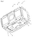
- einen Sensor mit einem Gehäuse und einer Aufnahme und einem Halter in einer Ansicht von unten;
- Figur 3
- eine perspektivische Ansicht des Sensors mit Aufnahme und Halter;
- Figur 4 und 5
- einen Sensor mit Aufnahme, Halter, erstem und zweitem U-förmigen Haltebügel in einer perspektivischen Ansicht;
- Figur 6
- einen Sensor mit Aufnahme, Halter, erstem und zweitem U-förmigen Haltebügel in einer Ansicht von vorne
- In den nachfolgenden Figuren sind identische Teile mit identischen Bezugszeichen versehen.
-
Figur 1 zeigt einen Sensor mit einem Gehäuse 2, wobei das Gehäuse 2 eine Aufnahme 3 für einen Halter 4 aufweist, wobei die Aufnahme wenigstens eine erste Referenzfläche 5 und wenigstens eine zweite Referenzfläche 6 aufweist, wobei der Halter 4 jeweils wenigstens eine dazu korrespondierende erste Referenzfläche 7 und wenigstens eine zweite Referenzfläche 8 aufweist, wobei die Aufnahme 3 des Gehäuses 2 wenigstens eine Befestigungsschraube 9 aufweist und die Befestigungsschraube 9 gegenüberliegend zu der zweiten Referenzfläche 6 an der Aufnahme 3 angeordnet ist und bei einer Befestigung durch die Befestigungsschraube die ersten Referenzflächen und die zweiten Referenzflächen aneinander liegen. - Durch die Referenzflächen 5, 6, 7 und 8 ist eine genaue Positionierung des Sensors 1 bzw. des Gehäuses 2 des Sensors 1 gewährleistet. Weiter ist eine gute Reproduzierbarkeit der Sensorposition bei einem Sensortausch gewährleistet, da ein Ersatzsensor nur wieder mit den Referenzflächen 5, 6, 7 und 8 des Halters 4 exakt ausgerichtet werden braucht, wodurch exakt die gleiche Position des Austauschsensors erreicht wird, wie die ursprüngliche Position des Sensors 1.
- Die Befestigungsschraube 9 liegt an einer Befestigungsfläche 17 des Halters 4 an. Die Befestigungsfläche 17 ist gegenüberliegend zur zweiten Referenzfläche 8 an dem Halter 4 angeordnet. Die Befestigungsfläche 17 ist gemäß
Figur 1 spiegelsymmetrisch zu der zweiten Referenzfläche 8 angeordnet und ausgebildet. - Die Befestigungsschraube 9 weist eine kegelförmige Schraubenspitze 18 auf. Die Fläche der kegelförmigen Schraubenspitze 18 liegt bei einer Befestigung an der Befestigungsfläche 17 des Halters 4 an. Durch die Befestigungsschraube 9 werden die ersten Referenzflächen 5, 7 und die zweiten Referenzflächen 6, 8 aneinander gedrückt.
- Gemäß
Figur 2 sind zwei identische Aufnahmen 3 in einem Abstand an dem Gehäuse 2 angeordnet und zwei korrespondierende identische Halter 4 in einem identischen Abstand angeordnet. - Gemäß
Figur 1 sind die ersten Referenzflächen 5, 7 und die zweiten Referenzflächen 6, 8 in unterschiedlichen Ebenen 10 angeordnet. Dadurch wird eine Referenzposition in zwei unterschiedlichen Richtungen gewährleistet. - Gemäß
Figur 1 sind die ersten Referenzflächen 5, 7 und die zweiten Referenzflächen 6, 8 in einem spitzen Winkel 11 angeordnet. Dadurch ist zum einen eine Referenzposition in zwei unterschiedlichen Richtungen gewährleistet. Weiter ist durch den spitzen Winkel 11 eine Keilform gebildet, wodurch der Halter 4 stabil zwischen den zwei Referenzflächen 5 und 6 fixiert ist. Durch die im spitzen Winkel 11 angeordneten Referenzflächen 5 und 6 bzw. 7 und 8 wird der Halter 4 zwangsläufig mechanisch in die richtige Position geführt, wodurch eine einfache Positionierung erreicht wird. - Gemäß
Figur 1 ist die Befestigungsschraube 9 eine Madenschraube 12. Eine Madenschraube 12 weist ein durchgängiges Gewinde auf, wobei der Schraubenkopf einen identischen Durchmesser wie das Gewinde aufweist und ebenso von dem Gewinde umgeben ist. - Gemäß
Figur 2 ist senkrecht zu der ersten Referenzfläche 5 bzw. 7 und senkrecht zu der zweiten Referenzfläche 6 bzw. 8 eine dritte Referenzfläche 13 angeordnet. Dadurch wird eine Referenzposition in drei unterschiedlichen Richtungen gewährleistet. Dadurch ist der Sensor 1 exakt und eindeutig bestimmbar fixiert. - Gemäß
Figur 3 ist der Sensor 1 eine Kamera 14, insbesondere eine 3D-Kamera. Bei der 3D-Kamera handelt es sich beispielsweise um eine Kamera, welche die Lichtlaufzeit auswertet, nämlich eine sogenannte Time-of-flight, kurz TOF-Kamera. Jedoch kann es sich bei der 3D-Kamera auch um eine Stereokamera zur Erfassung von Rauminformationen handeln. Derartige Kameras 14 werden durch die Aufnahme 3 und den Halter 4 exakt ausgerichtet, wodurch eine sehr genaue Position der Kamera 14 gewährleistet ist. - Gemäß
Figur 1 ist der Halter 4 aus Stahl, insbesondere aus rostfreiem Stahl. Dadurch ist der Halter 4 sehr robust und stabil ausgelegt. Jedoch kann der Halter 4 auch aus einer Aluminiumlegierung, aus einer Zinklegierung, aus einer Magnesiumlegierung oder auch aus Kunststoff gebildet sein. - Gemäß
Figur 3 besteht das Gehäuse 2 und die Aufnahme 3 aus Aluminiumdruckguss. Durch Aluminiumdruckguss können auch komplexere Gehäuseformen hergestellt werden, so dass die Aufnahme 3 einstückig mit dem Gehäuse 2 ausgebildet werden kann. Jedoch kann das Gehäuse 2 auch aus einer Aluminiumlegierung, aus einer Zinklegierung, aus Zinkdruckguss, aus einer Magnesiumlegierung oder auch aus Kunststoff gebildet sein. - Gemäß
Figur 4 ist an dem Halter 4 ein U-förmiger erster Haltebügel 15 angeordnet. Der U-förmige erste Haltebügel 15 erlaubt eine weitere Befestigung des Halters 4. Der U-förmige Haltebügel 15 weist hierzu zwei Seitenteile 19 auf. Zwischen den zwei Seitenteilen 19 ist ein Mittelteil 20 angeordnet. An dem Mittelteil 20 ist der Halter 4 angeordnet, beispielsweise mit Befestigungsschrauben 21 angeschraubt. Die Seitenteile 19 weisen ebenso Befestigungsöffnungen, beispielsweise bogen- oder teilkreisförmige Langlöcher auf. Der U-förmige erste Haltebügel 15 ist vorzugsweise einstückig ausgebildet. - Gemäß
Figur 4 ist an dem ersten Haltebügel 15 ein zweiter U-förmiger Haltebügel 16 angeordnet, wobei der erste Haltebügel 15 und der zweite Haltebügel 16 verdrehbar zueinander ausgebildet sind. Der U-förmige zweite Haltebügel 16 erlaubt eine weitere Befestigung des ersten Haltebügels 15. Der U-förmige zweite Haltebügel 16 weist hierzu zwei Seitenteile 19 auf. Zwischen den zwei Seitenteilen 19 ist ein Mittelteil 20 angeordnet. An dem Mittelteil 20 wird beispielsweise eine Verbindung mit einem Maschinenteil angebracht, beispielsweise mit Befestigungsschrauben 21 angeschraubt. Die Seitenteile 19 weisen ebenso Befestigungsöffnungen, beispielsweise bogen- oder teilkreisförmige Langlöcher auf. Der U-förmige erste Haltebügel 15 ist vorzugsweise einstückig ausgebildet. Über die bogen- oder teilkreisförmigen Langlöcher des ersten Haltebügels 15 und/oder des zweiten Haltebügels 16 wird mittels Befestigungsschrauben 21 eine verdrehbare Verbindung zwischen den Haltebügeln 15 und 16 ausgebildet. -
Figur 5 zeigt einen Sensor 1 mit Aufnahme 3, Halter 4, erstem und zweitem U-förmigen Haltebügel 15, 16 in einer weiteren perspektivischen Ansicht. -
Figur 6 zeigt einen Sensor 1 mit Aufnahme 3, Halter 4, erstem und zweitem U-förmigen Haltebügel 15, 16 in einer Ansicht von vorne. -
- 1
- Sensor
- 2
- Gehäuse
- 3
- Aufnahme
- 4
- Halter
- 5
- erste Referenzfläche der Aufnahme
- 6
- zweite Referenzfläche der Aufnahme
- 7
- erste Referenzfläche des Halters
- 8
- zweite Referenzfläche des Halters
- 9
- Befestigungsschraube
- 10
- Ebenen
- 11
- spitzen Winkel
- 12
- Madenschraube
- 13
- dritte Referenzfläche
- 14
- Kamera
- 15
- erster U-förmiger Haltebügel
- 16
- zweiter U-förmiger Haltebügel
- 17
- Befestigungsfläche
- 18
- kegelförmige Schraubenspitze
- 19
- Seitenteil
- 20
- Mittelteil
- 21
- Befestigungsschraube
Claims (10)
- Sensor mit einem Gehäuse (2), wobei das Gehäuse (2) eine Aufnahme (3) für einen Halter (4) aufweist, wobei die Aufnahme wenigstens eine erste Referenzfläche (5) und wenigstens eine zweite Referenzfläche (6) aufweist, wobei der Halter (4) jeweils wenigstens eine dazu korrespondierende erste Referenzfläche (7) und wenigstens eine zweite Referenzfläche (8) aufweist,
dadurch gekennzeichnet, dass
die Aufnahme (3) des Gehäuses (2) wenigstens eine Befestigungsschraube (9) aufweist und die Befestigungsschraube (9) gegenüberliegend zu der zweiten Referenzfläche (6) an der Aufnahme (3) angeordnet ist und bei einer Befestigung durch die Befestigungsschraube die ersten Referenzflächen und die zweiten Referenzflächen aneinander liegen. - Sensor nach Anspruch 1, dadurch gekennzeichnet, dass die ersten Referenzflächen (5, 7) und die zweiten Referenzflächen (6, 8) in unterschiedlichen Ebenen (10) angeordnet sind.
- Sensor nach einem der vorhergehenden Ansprüche, dadurch gekennzeichnet, dass die ersten Referenzflächen (5, 7) und die zweiten Referenzflächen (6, 8) in einem spitzen Winkel (11) zueinander angeordnet sind.
- Sensor nach einem der vorhergehenden Ansprüche, dadurch gekennzeichnet, dass die Befestigungsschraube (9) eine Madenschraube (12) ist.
- Sensor nach einem der vorhergehenden Ansprüche , dadurch gekennzeichnet, dass senkrecht zu der ersten Referenzfläche (5) und senkrecht zu der zweiten Referenzfläche (7) eine dritte Referenzfläche (13) angeordnet ist.
- Sensor nach einem der vorhergehenden Ansprüche, dadurch gekennzeichnet, dass der Sensor (1) eine Kamera (14), insbesondere eine 3D-Kamera ist.
- Sensor nach einem der vorhergehenden Ansprüche, dadurch gekennzeichnet, dass der Halter (4) aus Stahl ist.
- Sensor nach einem der vorhergehenden Ansprüche, dadurch gekennzeichnet, dass das Gehäuse (2) und die Aufnahme (3) aus Aluminiumdruckguss besteht.
- Sensor nach einem der vorhergehenden Ansprüche, dadurch gekennzeichnet, dass an dem Halter (4) ein U-förmiger erster Haltebügel (15) angeordnet ist.
- Sensor nach einem der vorhergehenden Ansprüche, dadurch gekennzeichnet, dass an dem ersten Haltebügel (15) ein zweiter U-förmiger Haltebügel (16) angeordnet ist, wobei der erste Haltebügel (15) und der zweite Haltebügel (16) verdrehbar zueinander ausgebildet sind.
Applications Claiming Priority (1)
| Application Number | Priority Date | Filing Date | Title |
|---|---|---|---|
| DE102015105824.3A DE102015105824A1 (de) | 2015-04-16 | 2015-04-16 | Sensor mit Gehäuse |
Publications (2)
| Publication Number | Publication Date |
|---|---|
| EP3082331A1 true EP3082331A1 (de) | 2016-10-19 |
| EP3082331B1 EP3082331B1 (de) | 2019-01-09 |
Family
ID=55637212
Family Applications (1)
| Application Number | Title | Priority Date | Filing Date |
|---|---|---|---|
| EP16161530.7A Active EP3082331B1 (de) | 2015-04-16 | 2016-03-22 | Sensor mit gehäuse |
Country Status (2)
| Country | Link |
|---|---|
| EP (1) | EP3082331B1 (de) |
| DE (1) | DE102015105824A1 (de) |
Families Citing this family (1)
| Publication number | Priority date | Publication date | Assignee | Title |
|---|---|---|---|---|
| DE202016007625U1 (de) * | 2016-12-15 | 2018-03-19 | Kuka Roboter Gmbh | Sensorhalterung für ein Fahrzeug |
Citations (7)
| Publication number | Priority date | Publication date | Assignee | Title |
|---|---|---|---|---|
| US4570887A (en) * | 1983-10-17 | 1986-02-18 | Banister Gerald K | Quick-connect mount for a camera and tripod |
| EP1069410A1 (de) * | 1999-07-12 | 2001-01-17 | Festo AG & Co | Vorrichtung zur lösbaren Verankerung eines Sensors |
| EP1533998B1 (de) | 2003-11-19 | 2011-01-26 | Sick Ag | Verfahren zum Austausch von Kameras |
| US20110042535A1 (en) * | 2009-08-18 | 2011-02-24 | Ming-Chung Cheng | Positioning apparatus for optical instrument |
| DE102010007320A1 (de) * | 2010-02-08 | 2011-08-11 | Power PLUS Communications AG, 68163 | Haltebügel zur Aufnahme eines Gehäuses und Gehäuse zur Aufnahme in einem Haltebügel |
| DE102013104974A1 (de) | 2013-05-15 | 2014-12-04 | Leuze Electronic Gmbh & Co. Kg | Befestigungseinheit für einen Sensor |
| CN204203336U (zh) * | 2014-11-19 | 2015-03-11 | 国网浙江省电力公司舟山供电公司 | 用于运维管理系统的电流采集装置 |
Family Cites Families (4)
| Publication number | Priority date | Publication date | Assignee | Title |
|---|---|---|---|---|
| US2791950A (en) * | 1954-09-17 | 1957-05-14 | Kenneth G Oppenheimer | Gauge device for camera equipment |
| US6762790B1 (en) * | 2002-12-20 | 2004-07-13 | Bendix Commercial Vehicle Systems Llc | Universal camera bracket that allows 180 degree of pitch adjustment |
| EP2667146A1 (de) * | 2012-05-22 | 2013-11-27 | inos Automationssoftware GmbH | Optische Anordnung die eine optische Sendeeinheit und eine optische Empfangseinheit beinhält |
| US8942550B1 (en) * | 2012-05-24 | 2015-01-27 | Milton Carter | Variable speed heat air gun and cooperating kit |
-
2015
- 2015-04-16 DE DE102015105824.3A patent/DE102015105824A1/de not_active Withdrawn
-
2016
- 2016-03-22 EP EP16161530.7A patent/EP3082331B1/de active Active
Patent Citations (7)
| Publication number | Priority date | Publication date | Assignee | Title |
|---|---|---|---|---|
| US4570887A (en) * | 1983-10-17 | 1986-02-18 | Banister Gerald K | Quick-connect mount for a camera and tripod |
| EP1069410A1 (de) * | 1999-07-12 | 2001-01-17 | Festo AG & Co | Vorrichtung zur lösbaren Verankerung eines Sensors |
| EP1533998B1 (de) | 2003-11-19 | 2011-01-26 | Sick Ag | Verfahren zum Austausch von Kameras |
| US20110042535A1 (en) * | 2009-08-18 | 2011-02-24 | Ming-Chung Cheng | Positioning apparatus for optical instrument |
| DE102010007320A1 (de) * | 2010-02-08 | 2011-08-11 | Power PLUS Communications AG, 68163 | Haltebügel zur Aufnahme eines Gehäuses und Gehäuse zur Aufnahme in einem Haltebügel |
| DE102013104974A1 (de) | 2013-05-15 | 2014-12-04 | Leuze Electronic Gmbh & Co. Kg | Befestigungseinheit für einen Sensor |
| CN204203336U (zh) * | 2014-11-19 | 2015-03-11 | 国网浙江省电力公司舟山供电公司 | 用于运维管理系统的电流采集装置 |
Also Published As
| Publication number | Publication date |
|---|---|
| DE102015105824A1 (de) | 2016-10-20 |
| EP3082331B1 (de) | 2019-01-09 |
Similar Documents
| Publication | Publication Date | Title |
|---|---|---|
| EP0015309A1 (de) | Vorrichtung zum Andrücken eines Lichtwellenleiters an ein photoelektrisches Bauelement | |
| DE10304259B4 (de) | Befestigung für eine Anzeigeeinheit | |
| DE102015107385B4 (de) | Verfahren zum Herstellen einer Kamera für ein Kraftfahrzeug mit elektrischem Verbinden einer Leiterplatte und einem Linsengehäuse, Kamera, Fahrerassistenzsystem sowie Kraftfahrzeug | |
| DE102009046944A1 (de) | Montagesystem und Verfahren zur Montage einer Trennwand an eine Halteeinrichtung sowie Vorrichtung zum Trennen von Bereichen | |
| EP3561364B1 (de) | Einrichtung zur justierung eines kamerawinkels sowie verwendung einer derartigen einrichtung | |
| DE102017003759A1 (de) | Einstelleinrichtung und Verfahren zum Justieren eines Sensors zur Objektdetektion an einem Fahrzeug | |
| EP3082331B1 (de) | Sensor mit gehäuse | |
| EP3467240A1 (de) | Verfahren zum endpositionierten montieren eines türgriffträgers und türgriffträgerbefestigungsset | |
| DE202014103670U1 (de) | Optoelektronischer Sensor | |
| EP1876320A1 (de) | Justierbarer Lichtschrankensender | |
| DE102015115361B4 (de) | Verfahren zum Herstellen einer Kamera für ein Kraftfahrzeug in Abhängigkeit von einer Schnittstelleneinrichtung, Kamera sowie Kraftfahrzeug | |
| WO2019110518A1 (de) | Gehäuseaufnahme für einen kfz-radarsensor | |
| DE102017222219A1 (de) | Sensoranordnung und kraftfahrzeug | |
| DE102008001133A1 (de) | Vorrichtung zur Befestigung eines Sensors | |
| DE202015101864U1 (de) | Sensor mit Gehäuse | |
| DE102013104974B4 (de) | Anordnung mit einer Befestigungseinheit und einem Sensor | |
| DE102012009135A1 (de) | Optisches System | |
| DE60304068T2 (de) | Halter und halterbasis mit einem keil | |
| EP1949041B1 (de) | Beschleunigungssensor | |
| DE202011050473U1 (de) | Justierbare Halterungsvorrichtung für einen Sensor | |
| DE102014112515B4 (de) | Bandmaßendstück | |
| DE102017005224B4 (de) | Haltemechanismus und -verfahren | |
| DE10149901A1 (de) | Befestigungsvorrichtung für Schnittstellenkarten | |
| DE10211956B4 (de) | Vorrichtung zum Anbringen optoelektrischer Komponenten auf einer Leiterplatte | |
| DE19803360C2 (de) | Verfahren zur Montage einer Positionsmeßeinrichtung und Vorrichtung zur Durchführung des Verfahrens |
Legal Events
| Date | Code | Title | Description |
|---|---|---|---|
| PUAI | Public reference made under article 153(3) epc to a published international application that has entered the european phase |
Free format text: ORIGINAL CODE: 0009012 |
|
| AK | Designated contracting states |
Kind code of ref document: A1 Designated state(s): AL AT BE BG CH CY CZ DE DK EE ES FI FR GB GR HR HU IE IS IT LI LT LU LV MC MK MT NL NO PL PT RO RS SE SI SK SM TR |
|
| AX | Request for extension of the european patent |
Extension state: BA ME |
|
| STAA | Information on the status of an ep patent application or granted ep patent |
Free format text: STATUS: REQUEST FOR EXAMINATION WAS MADE |
|
| 17P | Request for examination filed |
Effective date: 20170407 |
|
| RBV | Designated contracting states (corrected) |
Designated state(s): AL AT BE BG CH CY CZ DE DK EE ES FI FR GB GR HR HU IE IS IT LI LT LU LV MC MK MT NL NO PL PT RO RS SE SI SK SM TR |
|
| STAA | Information on the status of an ep patent application or granted ep patent |
Free format text: STATUS: EXAMINATION IS IN PROGRESS |
|
| 17Q | First examination report despatched |
Effective date: 20170703 |
|
| GRAP | Despatch of communication of intention to grant a patent |
Free format text: ORIGINAL CODE: EPIDOSNIGR1 |
|
| STAA | Information on the status of an ep patent application or granted ep patent |
Free format text: STATUS: GRANT OF PATENT IS INTENDED |
|
| GRAS | Grant fee paid |
Free format text: ORIGINAL CODE: EPIDOSNIGR3 |
|
| GRAA | (expected) grant |
Free format text: ORIGINAL CODE: 0009210 |
|
| STAA | Information on the status of an ep patent application or granted ep patent |
Free format text: STATUS: THE PATENT HAS BEEN GRANTED |
|
| INTG | Intention to grant announced |
Effective date: 20181121 |
|
| AK | Designated contracting states |
Kind code of ref document: B1 Designated state(s): AL AT BE BG CH CY CZ DE DK EE ES FI FR GB GR HR HU IE IS IT LI LT LU LV MC MK MT NL NO PL PT RO RS SE SI SK SM TR |
|
| REG | Reference to a national code |
Ref country code: GB Ref legal event code: FG4D Free format text: NOT ENGLISH |
|
| REG | Reference to a national code |
Ref country code: CH Ref legal event code: EP Ref country code: AT Ref legal event code: REF Ref document number: 1088770 Country of ref document: AT Kind code of ref document: T Effective date: 20190115 |
|
| REG | Reference to a national code |
Ref country code: IE Ref legal event code: FG4D Free format text: LANGUAGE OF EP DOCUMENT: GERMAN |
|
| REG | Reference to a national code |
Ref country code: DE Ref legal event code: R096 Ref document number: 502016003106 Country of ref document: DE |
|
| REG | Reference to a national code |
Ref country code: NL Ref legal event code: FP |
|
| REG | Reference to a national code |
Ref country code: LT Ref legal event code: MG4D |
|
| PG25 | Lapsed in a contracting state [announced via postgrant information from national office to epo] |
Ref country code: FI Free format text: LAPSE BECAUSE OF FAILURE TO SUBMIT A TRANSLATION OF THE DESCRIPTION OR TO PAY THE FEE WITHIN THE PRESCRIBED TIME-LIMIT Effective date: 20190109 Ref country code: PL Free format text: LAPSE BECAUSE OF FAILURE TO SUBMIT A TRANSLATION OF THE DESCRIPTION OR TO PAY THE FEE WITHIN THE PRESCRIBED TIME-LIMIT Effective date: 20190109 Ref country code: NO Free format text: LAPSE BECAUSE OF FAILURE TO SUBMIT A TRANSLATION OF THE DESCRIPTION OR TO PAY THE FEE WITHIN THE PRESCRIBED TIME-LIMIT Effective date: 20190409 Ref country code: SE Free format text: LAPSE BECAUSE OF FAILURE TO SUBMIT A TRANSLATION OF THE DESCRIPTION OR TO PAY THE FEE WITHIN THE PRESCRIBED TIME-LIMIT Effective date: 20190109 Ref country code: PT Free format text: LAPSE BECAUSE OF FAILURE TO SUBMIT A TRANSLATION OF THE DESCRIPTION OR TO PAY THE FEE WITHIN THE PRESCRIBED TIME-LIMIT Effective date: 20190509 Ref country code: ES Free format text: LAPSE BECAUSE OF FAILURE TO SUBMIT A TRANSLATION OF THE DESCRIPTION OR TO PAY THE FEE WITHIN THE PRESCRIBED TIME-LIMIT Effective date: 20190109 Ref country code: LT Free format text: LAPSE BECAUSE OF FAILURE TO SUBMIT A TRANSLATION OF THE DESCRIPTION OR TO PAY THE FEE WITHIN THE PRESCRIBED TIME-LIMIT Effective date: 20190109 |
|
| PG25 | Lapsed in a contracting state [announced via postgrant information from national office to epo] |
Ref country code: LV Free format text: LAPSE BECAUSE OF FAILURE TO SUBMIT A TRANSLATION OF THE DESCRIPTION OR TO PAY THE FEE WITHIN THE PRESCRIBED TIME-LIMIT Effective date: 20190109 Ref country code: RS Free format text: LAPSE BECAUSE OF FAILURE TO SUBMIT A TRANSLATION OF THE DESCRIPTION OR TO PAY THE FEE WITHIN THE PRESCRIBED TIME-LIMIT Effective date: 20190109 Ref country code: GR Free format text: LAPSE BECAUSE OF FAILURE TO SUBMIT A TRANSLATION OF THE DESCRIPTION OR TO PAY THE FEE WITHIN THE PRESCRIBED TIME-LIMIT Effective date: 20190410 Ref country code: IS Free format text: LAPSE BECAUSE OF FAILURE TO SUBMIT A TRANSLATION OF THE DESCRIPTION OR TO PAY THE FEE WITHIN THE PRESCRIBED TIME-LIMIT Effective date: 20190509 Ref country code: BG Free format text: LAPSE BECAUSE OF FAILURE TO SUBMIT A TRANSLATION OF THE DESCRIPTION OR TO PAY THE FEE WITHIN THE PRESCRIBED TIME-LIMIT Effective date: 20190409 Ref country code: HR Free format text: LAPSE BECAUSE OF FAILURE TO SUBMIT A TRANSLATION OF THE DESCRIPTION OR TO PAY THE FEE WITHIN THE PRESCRIBED TIME-LIMIT Effective date: 20190109 |
|
| REG | Reference to a national code |
Ref country code: DE Ref legal event code: R097 Ref document number: 502016003106 Country of ref document: DE |
|
| PG25 | Lapsed in a contracting state [announced via postgrant information from national office to epo] |
Ref country code: DK Free format text: LAPSE BECAUSE OF FAILURE TO SUBMIT A TRANSLATION OF THE DESCRIPTION OR TO PAY THE FEE WITHIN THE PRESCRIBED TIME-LIMIT Effective date: 20190109 Ref country code: EE Free format text: LAPSE BECAUSE OF FAILURE TO SUBMIT A TRANSLATION OF THE DESCRIPTION OR TO PAY THE FEE WITHIN THE PRESCRIBED TIME-LIMIT Effective date: 20190109 Ref country code: MC Free format text: LAPSE BECAUSE OF FAILURE TO SUBMIT A TRANSLATION OF THE DESCRIPTION OR TO PAY THE FEE WITHIN THE PRESCRIBED TIME-LIMIT Effective date: 20190109 Ref country code: AL Free format text: LAPSE BECAUSE OF FAILURE TO SUBMIT A TRANSLATION OF THE DESCRIPTION OR TO PAY THE FEE WITHIN THE PRESCRIBED TIME-LIMIT Effective date: 20190109 Ref country code: CZ Free format text: LAPSE BECAUSE OF FAILURE TO SUBMIT A TRANSLATION OF THE DESCRIPTION OR TO PAY THE FEE WITHIN THE PRESCRIBED TIME-LIMIT Effective date: 20190109 Ref country code: RO Free format text: LAPSE BECAUSE OF FAILURE TO SUBMIT A TRANSLATION OF THE DESCRIPTION OR TO PAY THE FEE WITHIN THE PRESCRIBED TIME-LIMIT Effective date: 20190109 |
|
| REG | Reference to a national code |
Ref country code: CH Ref legal event code: PL |
|
| PLBE | No opposition filed within time limit |
Free format text: ORIGINAL CODE: 0009261 |
|
| STAA | Information on the status of an ep patent application or granted ep patent |
Free format text: STATUS: NO OPPOSITION FILED WITHIN TIME LIMIT |
|
| PG25 | Lapsed in a contracting state [announced via postgrant information from national office to epo] |
Ref country code: SM Free format text: LAPSE BECAUSE OF FAILURE TO SUBMIT A TRANSLATION OF THE DESCRIPTION OR TO PAY THE FEE WITHIN THE PRESCRIBED TIME-LIMIT Effective date: 20190109 Ref country code: LU Free format text: LAPSE BECAUSE OF NON-PAYMENT OF DUE FEES Effective date: 20190322 |
|
| REG | Reference to a national code |
Ref country code: BE Ref legal event code: MM Effective date: 20190331 |
|
| 26N | No opposition filed |
Effective date: 20191010 |
|
| PG25 | Lapsed in a contracting state [announced via postgrant information from national office to epo] |
Ref country code: IE Free format text: LAPSE BECAUSE OF NON-PAYMENT OF DUE FEES Effective date: 20190322 Ref country code: LI Free format text: LAPSE BECAUSE OF NON-PAYMENT OF DUE FEES Effective date: 20190331 Ref country code: CH Free format text: LAPSE BECAUSE OF NON-PAYMENT OF DUE FEES Effective date: 20190331 |
|
| PG25 | Lapsed in a contracting state [announced via postgrant information from national office to epo] |
Ref country code: BE Free format text: LAPSE BECAUSE OF NON-PAYMENT OF DUE FEES Effective date: 20190331 Ref country code: SI Free format text: LAPSE BECAUSE OF FAILURE TO SUBMIT A TRANSLATION OF THE DESCRIPTION OR TO PAY THE FEE WITHIN THE PRESCRIBED TIME-LIMIT Effective date: 20190109 |
|
| PG25 | Lapsed in a contracting state [announced via postgrant information from national office to epo] |
Ref country code: TR Free format text: LAPSE BECAUSE OF FAILURE TO SUBMIT A TRANSLATION OF THE DESCRIPTION OR TO PAY THE FEE WITHIN THE PRESCRIBED TIME-LIMIT Effective date: 20190109 |
|
| PG25 | Lapsed in a contracting state [announced via postgrant information from national office to epo] |
Ref country code: MT Free format text: LAPSE BECAUSE OF FAILURE TO SUBMIT A TRANSLATION OF THE DESCRIPTION OR TO PAY THE FEE WITHIN THE PRESCRIBED TIME-LIMIT Effective date: 20190109 |
|
| PG25 | Lapsed in a contracting state [announced via postgrant information from national office to epo] |
Ref country code: CY Free format text: LAPSE BECAUSE OF FAILURE TO SUBMIT A TRANSLATION OF THE DESCRIPTION OR TO PAY THE FEE WITHIN THE PRESCRIBED TIME-LIMIT Effective date: 20190109 |
|
| PG25 | Lapsed in a contracting state [announced via postgrant information from national office to epo] |
Ref country code: HU Free format text: LAPSE BECAUSE OF FAILURE TO SUBMIT A TRANSLATION OF THE DESCRIPTION OR TO PAY THE FEE WITHIN THE PRESCRIBED TIME-LIMIT; INVALID AB INITIO Effective date: 20160322 |
|
| REG | Reference to a national code |
Ref country code: AT Ref legal event code: MM01 Ref document number: 1088770 Country of ref document: AT Kind code of ref document: T Effective date: 20210322 |
|
| PG25 | Lapsed in a contracting state [announced via postgrant information from national office to epo] |
Ref country code: MK Free format text: LAPSE BECAUSE OF FAILURE TO SUBMIT A TRANSLATION OF THE DESCRIPTION OR TO PAY THE FEE WITHIN THE PRESCRIBED TIME-LIMIT Effective date: 20190109 |
|
| PG25 | Lapsed in a contracting state [announced via postgrant information from national office to epo] |
Ref country code: AT Free format text: LAPSE BECAUSE OF NON-PAYMENT OF DUE FEES Effective date: 20210322 |
|
| REG | Reference to a national code |
Ref country code: DE Ref legal event code: R079 Ref document number: 502016003106 Country of ref document: DE Free format text: PREVIOUS MAIN CLASS: H04N0005225000 Ipc: H04N0023000000 |
|
| PGFP | Annual fee paid to national office [announced via postgrant information from national office to epo] |
Ref country code: IT Payment date: 20250331 Year of fee payment: 10 |
|
| PGFP | Annual fee paid to national office [announced via postgrant information from national office to epo] |
Ref country code: GB Payment date: 20260324 Year of fee payment: 11 |
|
| PGFP | Annual fee paid to national office [announced via postgrant information from national office to epo] |
Ref country code: DE Payment date: 20260320 Year of fee payment: 11 |
|
| PGFP | Annual fee paid to national office [announced via postgrant information from national office to epo] |
Ref country code: NL Payment date: 20260323 Year of fee payment: 11 |
|
| PGFP | Annual fee paid to national office [announced via postgrant information from national office to epo] |
Ref country code: FR Payment date: 20260324 Year of fee payment: 11 |
|
| PGFP | Annual fee paid to national office [announced via postgrant information from national office to epo] |
Ref country code: SK Payment date: 20260317 Year of fee payment: 11 |