EP3082298A1 - Slave device and method for controlling the same - Google Patents
Slave device and method for controlling the same Download PDFInfo
- Publication number
- EP3082298A1 EP3082298A1 EP16162599.1A EP16162599A EP3082298A1 EP 3082298 A1 EP3082298 A1 EP 3082298A1 EP 16162599 A EP16162599 A EP 16162599A EP 3082298 A1 EP3082298 A1 EP 3082298A1
- Authority
- EP
- European Patent Office
- Prior art keywords
- group
- control message
- data
- slave device
- slave
- Prior art date
- Legal status (The legal status is an assumption and is not a legal conclusion. Google has not performed a legal analysis and makes no representation as to the accuracy of the status listed.)
- Granted
Links
Images


Classifications
-
- H—ELECTRICITY
- H04—ELECTRIC COMMUNICATION TECHNIQUE
- H04L—TRANSMISSION OF DIGITAL INFORMATION, e.g. TELEGRAPHIC COMMUNICATION
- H04L67/00—Network arrangements or protocols for supporting network services or applications
- H04L67/01—Protocols
- H04L67/12—Protocols specially adapted for proprietary or special-purpose networking environments, e.g. medical networks, sensor networks, networks in vehicles or remote metering networks
- H04L67/125—Protocols specially adapted for proprietary or special-purpose networking environments, e.g. medical networks, sensor networks, networks in vehicles or remote metering networks involving control of end-device applications over a network
-
- H—ELECTRICITY
- H04—ELECTRIC COMMUNICATION TECHNIQUE
- H04L—TRANSMISSION OF DIGITAL INFORMATION, e.g. TELEGRAPHIC COMMUNICATION
- H04L12/00—Data switching networks
- H04L12/28—Data switching networks characterised by path configuration, e.g. LAN [Local Area Networks] or WAN [Wide Area Networks]
- H04L12/40—Bus networks
- H04L12/40169—Flexible bus arrangements
- H04L12/40176—Flexible bus arrangements involving redundancy
- H04L12/40202—Flexible bus arrangements involving redundancy by using a plurality of master stations
-
- H—ELECTRICITY
- H04—ELECTRIC COMMUNICATION TECHNIQUE
- H04L—TRANSMISSION OF DIGITAL INFORMATION, e.g. TELEGRAPHIC COMMUNICATION
- H04L12/00—Data switching networks
- H04L12/28—Data switching networks characterised by path configuration, e.g. LAN [Local Area Networks] or WAN [Wide Area Networks]
- H04L12/40—Bus networks
- H04L12/40052—High-speed IEEE 1394 serial bus
- H04L12/40071—Packet processing; Packet format
-
- H—ELECTRICITY
- H04—ELECTRIC COMMUNICATION TECHNIQUE
- H04L—TRANSMISSION OF DIGITAL INFORMATION, e.g. TELEGRAPHIC COMMUNICATION
- H04L12/00—Data switching networks
- H04L12/28—Data switching networks characterised by path configuration, e.g. LAN [Local Area Networks] or WAN [Wide Area Networks]
- H04L12/42—Loop networks
- H04L12/437—Ring fault isolation or reconfiguration
-
- H—ELECTRICITY
- H04—ELECTRIC COMMUNICATION TECHNIQUE
- H04L—TRANSMISSION OF DIGITAL INFORMATION, e.g. TELEGRAPHIC COMMUNICATION
- H04L41/00—Arrangements for maintenance, administration or management of data switching networks, e.g. of packet switching networks
- H04L41/08—Configuration management of networks or network elements
- H04L41/0893—Assignment of logical groups to network elements
-
- H—ELECTRICITY
- H04—ELECTRIC COMMUNICATION TECHNIQUE
- H04L—TRANSMISSION OF DIGITAL INFORMATION, e.g. TELEGRAPHIC COMMUNICATION
- H04L43/00—Arrangements for monitoring or testing data switching networks
- H04L43/10—Active monitoring, e.g. heartbeat, ping or trace-route
-
- H—ELECTRICITY
- H04—ELECTRIC COMMUNICATION TECHNIQUE
- H04L—TRANSMISSION OF DIGITAL INFORMATION, e.g. TELEGRAPHIC COMMUNICATION
- H04L67/00—Network arrangements or protocols for supporting network services or applications
- H04L67/01—Protocols
- H04L67/10—Protocols in which an application is distributed across nodes in the network
- H04L67/104—Peer-to-peer [P2P] networks
- H04L67/1044—Group management mechanisms
-
- H—ELECTRICITY
- H04—ELECTRIC COMMUNICATION TECHNIQUE
- H04L—TRANSMISSION OF DIGITAL INFORMATION, e.g. TELEGRAPHIC COMMUNICATION
- H04L43/00—Arrangements for monitoring or testing data switching networks
- H04L43/08—Monitoring or testing based on specific metrics, e.g. QoS, energy consumption or environmental parameters
- H04L43/0805—Monitoring or testing based on specific metrics, e.g. QoS, energy consumption or environmental parameters by checking availability
- H04L43/0817—Monitoring or testing based on specific metrics, e.g. QoS, energy consumption or environmental parameters by checking availability by checking functioning
Definitions
- the present disclosure relates to a slave device and a method for controlling the same.
- the devices may be divided into a master device and slave devices.
- the master device monitors operation of slave devices or transmits instructions or data required by the slave devices.
- a master device transmits a control message to each of the slave devices to control them.
- FIG. 1 is a diagram illustrating a data transmission scheme between a master device and slave devices in the related art.
- a master device M generates as many control messages as slave devices existing in the network. Then, the master device M transmits the generated control messages to the slave devices S 1 to S4, respectively.
- the slave devices S1 to S4 apply there to the received control messages from the master device M or transmit input data to the master device M as requested.
- the master device M in order to control the slave devices S 1 to S4, the master device M has to generate as many control messages as the slave devices S 1 to S4 in the network and transmits them to the slave devices S1 to S4, respectively.
- FIG. 2 is a diagram illustrating a data transmission scheme using the EtherCAT communications in the related art.
- a master device M packages output data items S1_In, S2_In, S3_In and S4_In each having a fixed size into a single control message to transmit it to the slave devices S1 to S4, respectively. Then, the master device M transmits the generated control message to the slave device S 1.
- the slave device S1 transmits the control message received from the master device M to the slave device S2 in a cut-through manner, and likewise the slave device S2 transmits the received control message to the slave device S3, and so on.
- the cut-through manner refers to a technique that a received message is transmitted as soon as the destination of the message is determined to thereby reduce standby time of the message.
- the slave device S1 receives a control message from the master device M, and extracts input data S1_In from the first field of the control message that is associated with the slave device S1. Subsequently, the slave device S1 writes output data S1_Out in the first field of the control message to transmit it to the slave device S2.
- the slave device S2 upon receiving the control message from the slave device S1, extracts input data S2_In from the second field of the control message that is associated with the slave device S2. Then, the slave device S2 writes output data S2_Out in the second field of the control message to transmit it to the slave device S3.
- the slave device S3 upon receiving the control message from the slave device S2, extracts input data S3_In from the third field of the control message that is associated with the slave device S3 to apply it thereto. Then, the slave device S3 writes output data S3_Out in the third field of the control message to transmit it to the slave device S4.
- the slave device S4 upon receiving the control message from the slave device S3, extracts input data S4_In from the fourth field of the control message that is associated with the slave device S4 to apply it thereto. Then, the slave device S4 writes output data S4_Out in the fourth field of the control message to transmit it to the master device M.
- the master device M may determine whether the slave devices S1 to S4 are operating normally based on the output data S1_Out, S2_Out, S3_Out and S4_Out, respectively, included in the received control message from the slave device S4.
- the master device M only has to generate a single control message regardless of the number of the slave devices S1 to S4. Therefore, the problem of the scheme described above with reference to FIG. 1 , i.e., increase in data traffic can be addressed. Further, according to the data transmission scheme using the EtherCAT communications as described above with referring to FIG. 2 , the data transmission time can be reduced via the hardware switching manner, i.e., the cut-through manner.
- slave devices S 1 to S4 cannot transmit other control messages while a control message is transmitted therebetween, in order to avoid data collision.
- control message generated by the master device M has fields of fixed sizes in which input data of each of the slave devices S 1 to S4 is stored, such that the size of data to be transmitted is limited. Further, for a network including a larger number of slave devices, the size of the data fields allocated to each of the slave devices decreases.
- the transmission delay of the control message increases linearly, such that it becomes difficult to control the slave devices in real-time.
- a slave device in a system comprising a master device and a plurality of groups of slave devices includes: a receiving port configured to receive a control message containing group data items each corresponding to the respective groups or the group data items; a transmitting port configured to transmit the control message or the group data items to another device; and a data processing unit configured to extract the group data items from the control message, to extract input data from the group data items, and to write output data onto the group data items, wherein the transmitting port transmits the control message to a next group before the data processing unit extracts the group data items from the control message.
- slave devices are grouped, and a master device transmits a control message containing group data items, so that data traffic can be reduced even if the number of the slave devices increases.
- a slave device in a group transmits a control message transmitted from a master device to a next group via cut-through switching manner, so that data traffic can be reduced.
- the size of data transmitted from a slave device to a master device can vary as required.
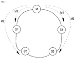
- FIG. 3 is a diagram illustrating a data transmission method between a master device and slave devices according to an exemplary embodiment of the present disclosure.
- a master device M is connected to a number of slave devices 200 existing in a network, and transmits input data items S1_In, S2_In, S3_In and S4_In contained in a control message 300 to the slave devices S1 to S4, respectively.
- the master device M may determine whether the slave devices S1 to S4 are operating normally based on the output data items S1_Out, S2_Out, S3_Out and S4_Out written onto the control message by the slave devices S 1 to S4, respectively.
- the slave devices S 1 to S4 are grouped into a plurality of groups G1 and G2 as shown in FIG. 3 .
- the first group G1 includes slave devices S1 and S2
- the second group G2 includes slave devices S3 and S4.
- four slave devices are grouped into two groups in the exemplary embodiment shown in FIGS. 3 and 4 for convenience of illustration, different numbers of slave devices may be grouped into different numbers of groups in other exemplary embodiments.
- six slave devices may be grouped into two groups each including three devices, or into three groups each including two devices.
- the master device M generates a control message 300 including first group data 301 and second group data 302.
- the first group data 301 contains input data items S1_In and S2_In to be transmitted to the slave devices S1 and S2, respectively, belonging to the first group G1.
- the second group data 302 contains input data items S3_In and S4_In to be transmitted to the slave devices S3 and S4, respectively, belonging to the second group G2.
- the master device M packages the first group data 301 and the second group data 302 into the control message 300 and transmit the generated control message 300 to the first group G1.
- the slave device S1 of the first group G1 receives the control message 300 from the master device M. Then, the slave device S1 may receive the control message 300, wait for a standby time, and transmit the control message 300 to the next group G2. That is, according to the exemplary embodiment of the present disclosure, after the groups G1 and G2 receive the control message 300, they transmit the control message 300 to the next group immediately before extracting the group data 301 and 302 from the control message 300, rather than transmitting the control message 300 to the next group after performing data processing (e.g., extracting input data or writing output data).
- data processing e.g., extracting input data or writing output data
- the groups transmit the control message 300 to the next group as soon as they receive the control message 300. Then, after the transmission of the control message 300 is completed, group data are extracted, input data items are extracted and output data items are written, which will be described below. Accordingly, it takes less time for the groups G1 and G2 to receive the control message 300, and thus increase in data traffic can be reduced even with more slave devices.
- the slave device S1 of the first group G1 may receive the control message 300, extract first group data 301 from the control message 300 and immediately transmit the control message 300 to the second group G2.
- the slave device S1 may extract an input data item S1_In from the first group data 301 extract from the control message 300. Then, the slave device S1 generates an output data item S1_Out at a predetermined data size for transmission to the master device M and writes it onto the first group data 301. That is, according to the exemplary embodiment of the present disclosure, the size of the output data item S1_Out may vary depending on a predetermined size, unlike in the related art. Then, the slave device S1 transmits the first group data 301 in which the output data S1_Out is written to the slave device S2 of the same group G1.
- the slave device S2 receives the first group data 301 from the slave device S1 and extracts an input data item S2_In therefrom. Then, the slave device S2 generates an output data item S2_Out at a predetermined data size for transmission to the master device M and writes it onto the first group data 301. Then, the slave device S2 sets the destination address of the first group data 301 to the address of the master device M and transmits the first group data 301 to the master device M.
- the first group data 301 transmitted by the slave device S2 may be transmitted to the master device M via the second group G2 or may be transmitted directly to the master device M.
- the slave device S4 of the second group G2 may receive the control message 300, extract second group data 302 from the control message 300 and then immediately transmit the control message 300 to the first group G1.
- the slave device S4 may extract an input data item S4_In from the second group data 302 extract from the control message 300, and then may generate an output data S4_Out for transmission to the master device M at a predetermined data size to write it onto the second group data 302. That is, according to the exemplary embodiment of the present disclosure, the size of the output data item S4_Out may vary depending on a predetermined size, unlike in the related art. Then, the slave device S4 may transmit the second group data 302 in which the output data S4_Out is written to the next slave device S3 of the same group G2.
- the slave device S3 may receive the second group data 302 from the slave device S4 to extract an input data item S3_In, and then may generate an output data S3_Out for transmission to the master device M at a predetermined data size to write it onto the second group data 302. Then, the slave device S3 sets the destination address of the second group data 302 to the address of the master device M and transmits the second group data 302 to the master device M.
- the second group data 302 transmitted by the slave device S3 may be transmitted to the master device M via the first group G1 or may be transmitted directly to the master device M.
- the control message 300 undergoes the same processing and transmission in the second group.
- the slave device S3 of the second group G2 extracts the second group data 302 from the control message 300 transmitted via the first group G1.
- the slave device S3 extracts the input data item S3_In from the second group data 302, and generates the output data item S3_Out at a predetermined data size to write it onto the second group data 302. Then, the slave device S3 transmits the second group data 302 in which the output data S3_Out is written to the slave device S4 of the same group G2.
- the slave device S4 receives an input data item S4_In from the second group data 302 received from the slave device S3. Then, the slave device S4 generates an output data item S4_Out at a predetermined data size for transmission to the master device M and writes it onto the second group data 302. Then, the slave device S4 sets the destination address of the second group data 302 to the address of the master device M and transmits the second group data 302 to the master device M.
- the master device M may determine whether the slave devices S1 to S4 are operating normally based on the output data item S1_Out, S2_Out, S3_Out and S4_Out written in the group data 301 and the group data 302 transmitted from the groups G1 and G2.
- the process of responding by the slave devices S1 to S4 to the master device M i.e., writing the output data items and transmitting the group data are performed at the group level. Accordingly, it takes less time to transmit data and it is possible to control the slave devices faster than in the related art in which slave devices response individually.
- FIG. 5 is a block diagram for illustrating a configuration of a slave device according to an exemplary embodiment of the present disclosure.
- a slave device 200 includes a receiving port 210, a transmitting port 220 and a data processing unit 230.
- the receiving port 210 receives a control message or group data corresponding to each of a plurality of groups. That is, the receiving port 210 may receive a control message containing group data transmitted from a master device or may receive group data transmitted from another slave device in the same group.
- the transmitting port 220 transmits the control message or the group data to another device. That is, the transmitting port 220 may transmit the control message transmitted from the master device or another group to the next group or may transmit the group data to another slave device in the same group.
- the transmitting port 220 may transmit the control message to the next group before the data processing unit 230 extracts the group data from the control message. According to another exemplary embodiment of the present disclosure, the transmitting port 220 may transmit the control message to the next group immediately after the data processing unit 230 extracts the group data from the control message.
- the data processing unit 230 extracts group data from the control message received from the receiving port 210, extracts input data from the extracted group data, and writes output data onto the control message.
- the size of the output data may vary depending on a predetermined data size.
- FIG. 6 is a message sequence chart illustrating a data transmission method between a master device and slave devices according to an exemplary embodiment of the present disclosure.
- a master device M generates a control message containing group data corresponding to each of a plurality of groups, and transmits the control message to a particular group among the plurality of groups (step S610).
- a slave device belonging to the particular group transmits the control message to the next group (step S620).
- the slave device included in the particular group After transmitting the control message to the next group, the slave device included in the particular group extracts group data from the control message (step S630).
- the slave device included in the particular group extracts/writes data from/to the group data (step S640).
- the slave device included in the particular group may extract input data from the group data while writing output data onto the group data simultaneously.
- the size of the output data may vary depending on a predetermined data size.
- the slave device included in the particular group transmits the group data to the master device M after completing extracting and writing data (step S650).
- the master device M determines whether the slave device included in the particular group is operating normally based on the output data contained in the group data (step S660).
Landscapes
- Engineering & Computer Science (AREA)
- Computer Networks & Wireless Communication (AREA)
- Signal Processing (AREA)
- Computing Systems (AREA)
- Health & Medical Sciences (AREA)
- General Health & Medical Sciences (AREA)
- Mathematical Physics (AREA)
- Physics & Mathematics (AREA)
- Theoretical Computer Science (AREA)
- Medical Informatics (AREA)
- Cardiology (AREA)
- Multimedia (AREA)
- Small-Scale Networks (AREA)
- Bus Control (AREA)
- Information Transfer Systems (AREA)
- Data Exchanges In Wide-Area Networks (AREA)
- Mobile Radio Communication Systems (AREA)
Abstract
Description
- The present disclosure relates to a slave device and a method for controlling the same.
- Typically, in a network with a number of devices connected thereto, the devices may be divided into a master device and slave devices. The master device monitors operation of slave devices or transmits instructions or data required by the slave devices. In general, when a network includes a large number of slave devices, a master device transmits a control message to each of the slave devices to control them.
-
FIG. 1 is a diagram illustrating a data transmission scheme between a master device and slave devices in the related art. Referring toFIG. 1 , a master device M generates as many control messages as slave devices existing in the network. Then, the master device M transmits the generated control messages to theslave devices S 1 to S4, respectively. The slave devices S1 to S4 apply there to the received control messages from the master device M or transmit input data to the master device M as requested. - In doing so, in order to control the
slave devices S 1 to S4, the master device M has to generate as many control messages as theslave devices S 1 to S4 in the network and transmits them to the slave devices S1 to S4, respectively. - However, according to this scheme, there is a problem in that data traffic increases as the number of slave devices increases and in turn the number of control messages increases. As a result, data transmission time increases and thus it becomes difficult to control the slave devices in real-time.
- To overcome this problem, there has been proposed a data transmission scheme using the EtherCAT communications.
-
FIG. 2 is a diagram illustrating a data transmission scheme using the EtherCAT communications in the related art. Referring toFIG. 2 , in order to control slave devices S1 to S4 in a network, a master device M packages output data items S1_In, S2_In, S3_In and S4_In each having a fixed size into a single control message to transmit it to the slave devices S1 to S4, respectively. Then, the master device M transmits the generated control message to theslave device S 1. - In the EtherCAT communications architecture shown in
FIG. 2 , the slave device S1 transmits the control message received from the master device M to the slave device S2 in a cut-through manner, and likewise the slave device S2 transmits the received control message to the slave device S3, and so on. The cut-through manner refers to a technique that a received message is transmitted as soon as the destination of the message is determined to thereby reduce standby time of the message. - Initially, the slave device S1 receives a control message from the master device M, and extracts input data S1_In from the first field of the control message that is associated with the slave device S1. Subsequently, the slave device S1 writes output data S1_Out in the first field of the control message to transmit it to the slave device S2.
- The slave device S2, upon receiving the control message from the slave device S1, extracts input data S2_In from the second field of the control message that is associated with the slave device S2. Then, the slave device S2 writes output data S2_Out in the second field of the control message to transmit it to the slave device S3.
- The slave device S3, upon receiving the control message from the slave device S2, extracts input data S3_In from the third field of the control message that is associated with the slave device S3 to apply it thereto. Then, the slave device S3 writes output data S3_Out in the third field of the control message to transmit it to the slave device S4.
- The slave device S4, upon receiving the control message from the slave device S3, extracts input data S4_In from the fourth field of the control message that is associated with the slave device S4 to apply it thereto. Then, the slave device S4 writes output data S4_Out in the fourth field of the control message to transmit it to the master device M.
- The master device M may determine whether the slave devices S1 to S4 are operating normally based on the output data S1_Out, S2_Out, S3_Out and S4_Out, respectively, included in the received control message from the slave device S4.
- According to the data transmission scheme using the EtherCAT communications as described above with referring to
FIG. 2 , the master device M only has to generate a single control message regardless of the number of the slave devices S1 to S4. Therefore, the problem of the scheme described above with reference toFIG. 1 , i.e., increase in data traffic can be addressed. Further, according to the data transmission scheme using the EtherCAT communications as described above with referring toFIG. 2 , the data transmission time can be reduced via the hardware switching manner, i.e., the cut-through manner. - Unfortunately, the
slave devices S 1 to S4 cannot transmit other control messages while a control message is transmitted therebetween, in order to avoid data collision. - In addition, the control message generated by the master device M has fields of fixed sizes in which input data of each of the
slave devices S 1 to S4 is stored, such that the size of data to be transmitted is limited. Further, for a network including a larger number of slave devices, the size of the data fields allocated to each of the slave devices decreases. - Furthermore, as the number of the slave devices increases, the transmission delay of the control message increases linearly, such that it becomes difficult to control the slave devices in real-time.
- It is an aspect of the present disclosure to provide a method for controlling a slave device in which slave devices are grouped, and a master device transmits a control message containing group data items, so that data traffic can be reduced even if the number of the slave devices increases.
- It is another aspect of the present disclosure to provide a method for controlling a slave device in which a slave device in a group transmits a control message transmitted from a master device to a next device via cut-through switching manner, so that data traffic can be reduced.
- It is yet another aspect of the present disclosure to provide a method for controlling a slave device in which the size of data transmitted from a slave device to a master device can vary as required.
- It should be noted that objects of the present disclosure are not limited to the above-described objects, and other objects of the present disclosure will be apparent to those skilled in the art from the following descriptions.
- In accordance with one aspect of the present disclosure, a method for controlling a slave device in a system comprising a master device and a plurality of groups of slave devices includes: generating, by the master device, a control message containing group data items each corresponding to the respective groups to transmit the control message to a particular group; transmitting, by a slave device included in the particular group, the control message to a next group; extracting, by the slave device, a group data item from the control message after the transmitting the control message; extracting/writing, by the slave device, data from/onto the group data; and transmitting, by the slave device, the group data to the master device after completing the extracting/writing.
- In accordance with another aspect of the present disclosure, a slave device in a system comprising a master device and a plurality of groups of slave devices includes: a receiving port configured to receive a control message containing group data items each corresponding to the respective groups or the group data items; a transmitting port configured to transmit the control message or the group data items to another device; and a data processing unit configured to extract the group data items from the control message, to extract input data from the group data items, and to write output data onto the group data items, wherein the transmitting port transmits the control message to a next group before the data processing unit extracts the group data items from the control message.
- The above described and other features are exemplified by the detailed description and accompanying drawings.
- Advantages and features of the present disclosure and methods to achieve them will become apparent from the descriptions of exemplary embodiments herein below with reference to the accompanying drawings. However, the present disclosure is not limited to exemplary embodiments disclosed herein but may be implemented in various different ways. The exemplary embodiments are provided for making the disclosure of the present disclosure thorough and for fully conveying the scope of the present disclosure to those skilled in the art. It is to be noted that the scope of the present disclosure is defined only by the claims. Like reference numerals denote like elements throughout the descriptions.
- According to an exemplary embodiment of the present disclosure, slave devices are grouped, and a master device transmits a control message containing group data items, so that data traffic can be reduced even if the number of the slave devices increases.
- According to another exemplary embodiment of the present disclosure, a slave device in a group transmits a control message transmitted from a master device to a next group via cut-through switching manner, so that data traffic can be reduced.
- In addition, according to an exemplary embodiment of the present disclosure, the size of data transmitted from a slave device to a master device can vary as required.
-
-
FIG. 1 is a diagram illustrating a data transmission scheme between a master device and slave devices in the related art; -
FIG. 2 is a diagram illustrating a data transmission scheme using the EtherCAT communications in the related art; -
FIGS. 3 and4 are diagrams illustrating a data transmission method between a master device and slave devices according to an exemplary embodiment of the present disclosure. -
FIG. 5 is a block diagram for illustrating a configuration of a slave device according to an exemplary embodiment of the present disclosure; and -
FIG. 6 is a message sequence chart illustrating a data transmission method between a master device and slave devices according to an exemplary embodiment of the present disclosure. - Hereinafter, exemplary embodiments of the present disclosure will be described in detail with reference to the accompanying drawings.
-
FIG. 3 is a diagram illustrating a data transmission method between a master device and slave devices according to an exemplary embodiment of the present disclosure. - Referring to
FIG. 3 , a master device M is connected to a number ofslave devices 200 existing in a network, and transmits input data items S1_In, S2_In, S3_In and S4_In contained in acontrol message 300 to the slave devices S1 to S4, respectively. In addition, the master device M may determine whether the slave devices S1 to S4 are operating normally based on the output data items S1_Out, S2_Out, S3_Out and S4_Out written onto the control message by theslave devices S 1 to S4, respectively. - It is to be noted that according to the exemplary embodiment, the
slave devices S 1 to S4 are grouped into a plurality of groups G1 and G2 as shown inFIG. 3 . InFIG. 3 , the first group G1 includes slave devices S1 and S2, and the second group G2 includes slave devices S3 and S4. Although four slave devices are grouped into two groups in the exemplary embodiment shown inFIGS. 3 and4 for convenience of illustration, different numbers of slave devices may be grouped into different numbers of groups in other exemplary embodiments. For example, according to an exemplary embodiment of the present disclosure, six slave devices may be grouped into two groups each including three devices, or into three groups each including two devices. - Accordingly, the master device M generates a
control message 300 includingfirst group data 301 andsecond group data 302. Thefirst group data 301 contains input data items S1_In and S2_In to be transmitted to the slave devices S1 and S2, respectively, belonging to the first group G1. Thesecond group data 302 contains input data items S3_In and S4_In to be transmitted to the slave devices S3 and S4, respectively, belonging to the second group G2. The master device M packages thefirst group data 301 and thesecond group data 302 into thecontrol message 300 and transmit the generatedcontrol message 300 to the first group G1. - Referring to
FIG. 4 , the slave device S1 of the first group G1 receives thecontrol message 300 from the master device M. Then, the slave device S1 may receive thecontrol message 300, wait for a standby time, and transmit thecontrol message 300 to the next group G2. That is, according to the exemplary embodiment of the present disclosure, after the groups G1 and G2 receive thecontrol message 300, they transmit thecontrol message 300 to the next group immediately before extracting thegroup data control message 300, rather than transmitting thecontrol message 300 to the next group after performing data processing (e.g., extracting input data or writing output data). - In other words, according to the exemplary embodiment of the present disclosure, the groups transmit the
control message 300 to the next group as soon as they receive thecontrol message 300. Then, after the transmission of thecontrol message 300 is completed, group data are extracted, input data items are extracted and output data items are written, which will be described below. Accordingly, it takes less time for the groups G1 and G2 to receive thecontrol message 300, and thus increase in data traffic can be reduced even with more slave devices. - On the other hand, according to another exemplary embodiment of the present disclosure, the slave device S1 of the first group G1 may receive the
control message 300, extractfirst group data 301 from thecontrol message 300 and immediately transmit thecontrol message 300 to the second group G2. - The slave device S1 may extract an input data item S1_In from the
first group data 301 extract from thecontrol message 300. Then, the slave device S1 generates an output data item S1_Out at a predetermined data size for transmission to the master device M and writes it onto thefirst group data 301. That is, according to the exemplary embodiment of the present disclosure, the size of the output data item S1_Out may vary depending on a predetermined size, unlike in the related art. Then, the slave device S1 transmits thefirst group data 301 in which the output data S1_Out is written to the slave device S2 of the same group G1. - The slave device S2 receives the
first group data 301 from the slave device S1 and extracts an input data item S2_In therefrom. Then, the slave device S2 generates an output data item S2_Out at a predetermined data size for transmission to the master device M and writes it onto thefirst group data 301. Then, the slave device S2 sets the destination address of thefirst group data 301 to the address of the master device M and transmits thefirst group data 301 to the master device M. Thefirst group data 301 transmitted by the slave device S2 may be transmitted to the master device M via the second group G2 or may be transmitted directly to the master device M. - In addition, according to yet another exemplary embodiment of the present disclosure, the slave device S4 of the second group G2 may receive the
control message 300, extractsecond group data 302 from thecontrol message 300 and then immediately transmit thecontrol message 300 to the first group G1. - The slave device S4 may extract an input data item S4_In from the
second group data 302 extract from thecontrol message 300, and then may generate an output data S4_Out for transmission to the master device M at a predetermined data size to write it onto thesecond group data 302. That is, according to the exemplary embodiment of the present disclosure, the size of the output data item S4_Out may vary depending on a predetermined size, unlike in the related art. Then, the slave device S4 may transmit thesecond group data 302 in which the output data S4_Out is written to the next slave device S3 of the same group G2. - The slave device S3 may receive the
second group data 302 from the slave device S4 to extract an input data item S3_In, and then may generate an output data S3_Out for transmission to the master device M at a predetermined data size to write it onto thesecond group data 302. Then, the slave device S3 sets the destination address of thesecond group data 302 to the address of the master device M and transmits thesecond group data 302 to the master device M. Thesecond group data 302 transmitted by the slave device S3 may be transmitted to the master device M via the first group G1 or may be transmitted directly to the master device M. - The
control message 300 undergoes the same processing and transmission in the second group. The slave device S3 of the second group G2 extracts thesecond group data 302 from thecontrol message 300 transmitted via the first group G1. - The slave device S3 extracts the input data item S3_In from the
second group data 302, and generates the output data item S3_Out at a predetermined data size to write it onto thesecond group data 302. Then, the slave device S3 transmits thesecond group data 302 in which the output data S3_Out is written to the slave device S4 of the same group G2. - The slave device S4 receives an input data item S4_In from the
second group data 302 received from the slave device S3. Then, the slave device S4 generates an output data item S4_Out at a predetermined data size for transmission to the master device M and writes it onto thesecond group data 302. Then, the slave device S4 sets the destination address of thesecond group data 302 to the address of the master device M and transmits thesecond group data 302 to the master device M. - The master device M may determine whether the slave devices S1 to S4 are operating normally based on the output data item S1_Out, S2_Out, S3_Out and S4_Out written in the
group data 301 and thegroup data 302 transmitted from the groups G1 and G2. - As described above, according to the exemplary embodiment of the present disclosure, the process of responding by the slave devices S1 to S4 to the master device M, i.e., writing the output data items and transmitting the group data are performed at the group level. Accordingly, it takes less time to transmit data and it is possible to control the slave devices faster than in the related art in which slave devices response individually.
-
FIG. 5 is a block diagram for illustrating a configuration of a slave device according to an exemplary embodiment of the present disclosure. - Referring to
FIG. 5 , aslave device 200 includes a receivingport 210, a transmittingport 220 and adata processing unit 230. - The receiving
port 210 receives a control message or group data corresponding to each of a plurality of groups. That is, the receivingport 210 may receive a control message containing group data transmitted from a master device or may receive group data transmitted from another slave device in the same group. - The transmitting
port 220 transmits the control message or the group data to another device. That is, the transmittingport 220 may transmit the control message transmitted from the master device or another group to the next group or may transmit the group data to another slave device in the same group. - According to an exemplary embodiment of the present disclosure, the transmitting
port 220 may transmit the control message to the next group before thedata processing unit 230 extracts the group data from the control message. According to another exemplary embodiment of the present disclosure, the transmittingport 220 may transmit the control message to the next group immediately after thedata processing unit 230 extracts the group data from the control message. - The
data processing unit 230 extracts group data from the control message received from the receivingport 210, extracts input data from the extracted group data, and writes output data onto the control message. The size of the output data may vary depending on a predetermined data size. -
FIG. 6 is a message sequence chart illustrating a data transmission method between a master device and slave devices according to an exemplary embodiment of the present disclosure. - Referring to
FIG. 6 , a master device M generates a control message containing group data corresponding to each of a plurality of groups, and transmits the control message to a particular group among the plurality of groups (step S610). - A slave device belonging to the particular group transmits the control message to the next group (step S620).
- After transmitting the control message to the next group, the slave device included in the particular group extracts group data from the control message (step S630).
- Subsequently, the slave device included in the particular group extracts/writes data from/to the group data (step S640). In an example of step S640, the slave device included in the particular group may extract input data from the group data while writing output data onto the group data simultaneously. The size of the output data may vary depending on a predetermined data size.
- The slave device included in the particular group transmits the group data to the master device M after completing extracting and writing data (step S650).
- The master device M determines whether the slave device included in the particular group is operating normally based on the output data contained in the group data (step S660).
- Thus far, although specific exemplary embodiments of the present disclosure have been described, various modifications may be made without departing from the scope of the present disclosure. Accordingly, the scope of the present disclosure is not construed as being limited to the above-described exemplary embodiments, but is defined solely by the following claims as well as equivalents thereof.
- Although the present disclosure has been described with reference to the exemplary embodiments and the accompanying drawings, it is not limited to the above-described exemplary embodiments, but may be variously modified and altered from the above description by those skilled in the art. Therefore, the scope and spirit of the present disclosure should be defined only by the following claims, and all of the equivalences and equivalent modifications of the claims should be intended to fall within the scope and spirit of the present disclosure.
Claims (6)
- A method for controlling a slave device in a system comprising a master device and a plurality of groups of slave devices, the method comprising:generating, by the master device, a control message containing group data items each corresponding to the respective groups to transmit the control message to a particular group (S610);transmitting, by a slave device included in the particular group, the control message to a next group (S620);extracting, by the slave device, a group data item from the control message after the transmitting the control message (S630);extracting, by the slave device, input data from the group data item (S640);writing, by the slave device, output data onto the group data item (S640); andtransmitting, by the slave device, the group data to the master device after completing the extracting the input data and the writing the output data (S650).
- The method of claim 1, wherein a size of the output data varies depending on a predetermined data size.
- The method of claim 1, further comprising:determining, by the master device, whether the slave devices included in the plurality of groups are operating normally based on the output data contained in the group data items transmitted from the plurality of groups (S660).
- A slave device in a system comprising a master device and a plurality of groups of slave devices, the slave device comprising:a receiving port (210) configured to receive a control message containing group data items each corresponding to the respective groups or the group data items;a transmitting port (230) configured to transmit the control message or the group data items to another device; anda data processing unit (220) configured to extract the group data items from the control message, to extract input data from the group data items, and to write output data onto the group data items,wherein the transmitting port (230) transmits the control message to a next group before the data processing unit (220) extracts the group data items from the control message.
- The slave device of claim 4, wherein a size of the output data varies depending on a predetermined data size.
- The slave device of claim 4, wherein the master device determines whether the slave devices included in the plurality of groups are operating normally based on the output data contained in the group data items transmitted from the plurality of groups.
Applications Claiming Priority (1)
| Application Number | Priority Date | Filing Date | Title |
|---|---|---|---|
| KR1020150054788A KR102023534B1 (en) | 2015-04-17 | 2015-04-17 | Slave device and mehtod controlling thereof |
Publications (2)
| Publication Number | Publication Date |
|---|---|
| EP3082298A1 true EP3082298A1 (en) | 2016-10-19 |
| EP3082298B1 EP3082298B1 (en) | 2018-07-11 |
Family
ID=56008446
Family Applications (1)
| Application Number | Title | Priority Date | Filing Date |
|---|---|---|---|
| EP16162599.1A Active EP3082298B1 (en) | 2015-04-17 | 2016-03-29 | Slave device and method for controlling the same |
Country Status (6)
| Country | Link |
|---|---|
| US (1) | US10348835B2 (en) |
| EP (1) | EP3082298B1 (en) |
| JP (1) | JP6220916B2 (en) |
| KR (1) | KR102023534B1 (en) |
| CN (1) | CN106059873B (en) |
| ES (1) | ES2686943T3 (en) |
Citations (3)
| Publication number | Priority date | Publication date | Assignee | Title |
|---|---|---|---|---|
| JP2006332787A (en) * | 2005-05-23 | 2006-12-07 | Sogo Keibi Hosho Co Ltd | Monitoring system, monitoring terminal, terminal to be monitored, life-and-death monitoring program, and life-and-death monitoring response program |
| WO2009088574A1 (en) * | 2008-01-11 | 2009-07-16 | Mosaid Technologies, Inc. | Ring-of-clusters network topologies |
| JP2010062855A (en) * | 2008-09-03 | 2010-03-18 | Fujitsu Ltd | Health check in wireless communications network |
Family Cites Families (30)
| Publication number | Priority date | Publication date | Assignee | Title |
|---|---|---|---|---|
| JPH10161952A (en) * | 1996-11-27 | 1998-06-19 | Toshiba Corp | Computer fault monitoring method and system |
| JP4204226B2 (en) | 2001-12-28 | 2009-01-07 | 日本テキサス・インスツルメンツ株式会社 | Device identification method, data transmission method, device identifier assigning apparatus, and device |
| JP2006107022A (en) * | 2004-10-04 | 2006-04-20 | Canon Inc | Method and apparatus for inter-module communication using layered rings |
| JP4564411B2 (en) | 2005-06-17 | 2010-10-20 | 株式会社三栄水栓製作所 | Drain valve |
| US8072999B1 (en) * | 2007-05-08 | 2011-12-06 | Motion Engineering Inc. | Method and system for removing and returning nodes in a synchronous network |
| WO2009012604A1 (en) * | 2007-07-20 | 2009-01-29 | Ferag Ag | Method and device for inserting, collecting or collating a plurality of flexible, planar products |
| BRPI0822259A2 (en) | 2008-02-06 | 2023-04-18 | Siemens Ag | GROUP MASTER COMMUNICATION SYSTEM AND METHOD FOR SERIES TRANSMITTING DATA IN AUTOMATION TECHNOLOGY |
| KR20100078193A (en) * | 2008-12-30 | 2010-07-08 | 주식회사 동부하이텍 | Slave and method for communicating between the slave and master |
| JP2011029002A (en) * | 2009-07-24 | 2011-02-10 | Panasonic Electric Works Co Ltd | High-pressure discharge lamp lighting device and lighting fixture using the same, and lighting system |
| ATE552672T1 (en) * | 2009-07-31 | 2012-04-15 | Abb Research Ltd | DATA TRANSMISSION IN A RING COMMUNICATIONS NETWORK |
| JP5411725B2 (en) * | 2010-01-27 | 2014-02-12 | 株式会社日立産機システム | CONTROL NETWORK SYSTEM, MASTER DEVICE, CONTROL DATA PROCESSING METHOD, AND CONTROL DATA PROCESSING PROGRAM |
| JP5394283B2 (en) * | 2010-02-25 | 2014-01-22 | 株式会社日立産機システム | Information processing apparatus and control network system |
| DE102010003448A1 (en) * | 2010-03-30 | 2011-10-06 | Beckhoff Automation Gmbh | Addressing method and communication network with such an addressing method |
| US20120041599A1 (en) * | 2010-08-11 | 2012-02-16 | Townsend William T | Teleoperator system with master controller device and multiple remote slave devices |
| JP5229343B2 (en) * | 2011-03-15 | 2013-07-03 | オムロン株式会社 | Connection abnormality detection method, network system, and master device |
| US8120935B2 (en) * | 2011-03-29 | 2012-02-21 | American Superconductor Corporation | Power converter with dual ring network control |
| WO2013064867A1 (en) * | 2011-11-04 | 2013-05-10 | Freescale Semiconductor, Inc. | Real-time distributed network slave device, real-time distributed network and method therefor |
| EP2774336B1 (en) * | 2011-11-04 | 2020-01-08 | NXP USA, Inc. | Real-time distributed network module, real-time distributed network and method therefor |
| US20130173868A1 (en) * | 2011-12-29 | 2013-07-04 | Texas Instruments Incorporated | Generation of Activation List for Memory Translation and Memory Access Protection in Industrial Ethernet Standard |
| CN104126155B (en) * | 2012-03-15 | 2017-06-09 | 欧姆龙株式会社 | Control device, information processing device, control method |
| US9266518B2 (en) * | 2013-11-08 | 2016-02-23 | GM Global Technology Operations LLC | Component control system for a vehicle |
| JP6390113B2 (en) * | 2014-02-14 | 2018-09-19 | オムロン株式会社 | Control system, development support apparatus, control apparatus, and control method |
| KR102225329B1 (en) * | 2014-03-03 | 2021-03-09 | 삼성전자주식회사 | EtherCAT CONTROL DEVICE AND FACTORY AUTOMATION SYSTEM HAVING THE SAME |
| WO2015133175A1 (en) * | 2014-03-04 | 2015-09-11 | オムロン株式会社 | Control system, control device, and control method |
| DE102014105207B4 (en) * | 2014-04-11 | 2015-10-22 | Beckhoff Automation Gmbh | Method for operating a communication network and communication network |
| DE102014006231A1 (en) * | 2014-04-30 | 2015-11-05 | Omron Corporation | Connecting multiple slave units to a master controller in a distributed controller system |
| DE102014112082A1 (en) * | 2014-08-22 | 2016-02-25 | Beckhoff Automation Gmbh | Distribution hub, automation network and method for transmitting real-time-relevant and non-real-time-relevant data packets |
| JP6465620B2 (en) * | 2014-10-31 | 2019-02-06 | ヤマハ発動機株式会社 | Control system and control method |
| US20170009915A1 (en) * | 2015-07-07 | 2017-01-12 | United Technologies Corporation | Integrated metal c-seal with threaded adapter |
| JP6846111B2 (en) * | 2016-02-26 | 2021-03-24 | オムロン株式会社 | Master device, slave device, information processing device, event log collection system, master device control method, slave device control method, and control program |
-
2015
- 2015-04-17 KR KR1020150054788A patent/KR102023534B1/en active Active
-
2016
- 2016-03-29 EP EP16162599.1A patent/EP3082298B1/en active Active
- 2016-03-29 ES ES16162599.1T patent/ES2686943T3/en active Active
- 2016-04-14 JP JP2016081023A patent/JP6220916B2/en active Active
- 2016-04-15 US US15/130,548 patent/US10348835B2/en active Active
- 2016-04-15 CN CN201610237213.5A patent/CN106059873B/en active Active
Patent Citations (3)
| Publication number | Priority date | Publication date | Assignee | Title |
|---|---|---|---|---|
| JP2006332787A (en) * | 2005-05-23 | 2006-12-07 | Sogo Keibi Hosho Co Ltd | Monitoring system, monitoring terminal, terminal to be monitored, life-and-death monitoring program, and life-and-death monitoring response program |
| WO2009088574A1 (en) * | 2008-01-11 | 2009-07-16 | Mosaid Technologies, Inc. | Ring-of-clusters network topologies |
| JP2010062855A (en) * | 2008-09-03 | 2010-03-18 | Fujitsu Ltd | Health check in wireless communications network |
Non-Patent Citations (1)
| Title |
|---|
| SHAH & M YIP EXTREME NETWORKS S: "Extreme Networks' Ethernet Automatic Protection Switching (EAPS), Version 1; draft-shah-extreme-eaps-01.txt", 5. JCT-VC MEETING; 96. MPEG MEETING; 16-3-2011 - 23-3-2011; GENEVA; (JOINT COLLABORATIVE TEAM ON VIDEO CODING OF ISO/IEC JTC1/SC29/WG11 AND ITU-T SG.16 ); URL: HTTP://WFTP3.ITU.INT/AV-ARCH/JCTVC-SITE/, INTERNET ENGINEERING TASK FORCE, IETF, CH, no. 1, 10 January 2003 (2003-01-10), XP015035158, ISSN: 0000-0004 * |
Also Published As
| Publication number | Publication date |
|---|---|
| KR20160124394A (en) | 2016-10-27 |
| ES2686943T3 (en) | 2018-10-22 |
| US10348835B2 (en) | 2019-07-09 |
| JP2016207209A (en) | 2016-12-08 |
| EP3082298B1 (en) | 2018-07-11 |
| JP6220916B2 (en) | 2017-10-25 |
| CN106059873B (en) | 2019-09-20 |
| CN106059873A (en) | 2016-10-26 |
| US20160308973A1 (en) | 2016-10-20 |
| KR102023534B1 (en) | 2019-09-23 |
Similar Documents
| Publication | Publication Date | Title |
|---|---|---|
| US10572290B2 (en) | Method and apparatus for allocating a physical resource to a virtual machine | |
| US9634888B2 (en) | Method and system for transmitting data in parallel via wireless link and wired link | |
| US20200076713A1 (en) | Slave-to-master data and out-of-sequence acknowledgements on a daisy-chained bus | |
| JP2018503995A (en) | Apparatus and method for buffering data in a switch | |
| US11671678B2 (en) | Method and device, equipment, and storage medium for data processing | |
| EP3035193A1 (en) | Memory module access method and device | |
| CN106330741B (en) | Message transmission method and device | |
| US10277502B2 (en) | Slave device control method | |
| CN113742075A (en) | Task processing method, device and system based on cloud distributed system | |
| CN104158683A (en) | Cross-device aggregation group rapid convergence method, and cross-device aggregation group rapid convergence device | |
| EP2038744B1 (en) | Method and system of grouping interrupts from a time-dependent data storage means | |
| CN104780120A (en) | Method and device for transmitting files in local area network | |
| CN102843247A (en) | Method and system for concurrently processing network element message | |
| CN108271212B (en) | Resource selection mechanism determination method and device | |
| US10728178B2 (en) | Apparatus and method for distribution of congestion information in a switch | |
| US10348835B2 (en) | Slave device and method for controlling the same | |
| US20090319733A1 (en) | System and Method for Aggregating Transmit Completion Interrupts | |
| CN105512079A (en) | Parallel package assembly method for multichannel stream data of 1394 bus | |
| KR102416176B1 (en) | Slave device control method | |
| EP2036262A1 (en) | Method for transmitting a datum from a time-dependent data storage means | |
| CN109582242A (en) | The address of cascade memory array system determines method, apparatus, electronic equipment | |
| CN103051528B (en) | A kind of message rapid distribution method for bus and device | |
| EP2922244A1 (en) | Media access control filtering apparatus for high speed switching and operating method thereof | |
| US9794197B2 (en) | Method and apparatus for transmitting can frame | |
| CN105323160A (en) | Message transmitting-receiving method and device, channel unit and communication device |
Legal Events
| Date | Code | Title | Description |
|---|---|---|---|
| PUAI | Public reference made under article 153(3) epc to a published international application that has entered the european phase |
Free format text: ORIGINAL CODE: 0009012 |
|
| AK | Designated contracting states |
Kind code of ref document: A1 Designated state(s): AL AT BE BG CH CY CZ DE DK EE ES FI FR GB GR HR HU IE IS IT LI LT LU LV MC MK MT NL NO PL PT RO RS SE SI SK SM TR |
|
| AX | Request for extension of the european patent |
Extension state: BA ME |
|
| STAA | Information on the status of an ep patent application or granted ep patent |
Free format text: STATUS: REQUEST FOR EXAMINATION WAS MADE |
|
| 17P | Request for examination filed |
Effective date: 20170418 |
|
| RBV | Designated contracting states (corrected) |
Designated state(s): AL AT BE BG CH CY CZ DE DK EE ES FI FR GB GR HR HU IE IS IT LI LT LU LV MC MK MT NL NO PL PT RO RS SE SI SK SM TR |
|
| STAA | Information on the status of an ep patent application or granted ep patent |
Free format text: STATUS: EXAMINATION IS IN PROGRESS |
|
| 17Q | First examination report despatched |
Effective date: 20171123 |
|
| GRAP | Despatch of communication of intention to grant a patent |
Free format text: ORIGINAL CODE: EPIDOSNIGR1 |
|
| STAA | Information on the status of an ep patent application or granted ep patent |
Free format text: STATUS: GRANT OF PATENT IS INTENDED |
|
| RIC1 | Information provided on ipc code assigned before grant |
Ipc: H04L 12/437 20060101ALN20180419BHEP Ipc: H04L 12/24 20060101ALI20180419BHEP Ipc: H04L 12/26 20060101AFI20180419BHEP Ipc: H04L 29/06 20060101ALN20180419BHEP |
|
| INTG | Intention to grant announced |
Effective date: 20180504 |
|
| GRAS | Grant fee paid |
Free format text: ORIGINAL CODE: EPIDOSNIGR3 |
|
| GRAA | (expected) grant |
Free format text: ORIGINAL CODE: 0009210 |
|
| STAA | Information on the status of an ep patent application or granted ep patent |
Free format text: STATUS: THE PATENT HAS BEEN GRANTED |
|
| AK | Designated contracting states |
Kind code of ref document: B1 Designated state(s): AL AT BE BG CH CY CZ DE DK EE ES FI FR GB GR HR HU IE IS IT LI LT LU LV MC MK MT NL NO PL PT RO RS SE SI SK SM TR |
|
| REG | Reference to a national code |
Ref country code: GB Ref legal event code: FG4D |
|
| REG | Reference to a national code |
Ref country code: CH Ref legal event code: EP |
|
| REG | Reference to a national code |
Ref country code: AT Ref legal event code: REF Ref document number: 1018061 Country of ref document: AT Kind code of ref document: T Effective date: 20180715 |
|
| REG | Reference to a national code |
Ref country code: IE Ref legal event code: FG4D |
|
| REG | Reference to a national code |
Ref country code: DE Ref legal event code: R096 Ref document number: 602016004017 Country of ref document: DE |
|
| REG | Reference to a national code |
Ref country code: ES Ref legal event code: FG2A Ref document number: 2686943 Country of ref document: ES Kind code of ref document: T3 Effective date: 20181022 |
|
| REG | Reference to a national code |
Ref country code: NL Ref legal event code: MP Effective date: 20180711 |
|
| REG | Reference to a national code |
Ref country code: LT Ref legal event code: MG4D |
|
| REG | Reference to a national code |
Ref country code: AT Ref legal event code: MK05 Ref document number: 1018061 Country of ref document: AT Kind code of ref document: T Effective date: 20180711 |
|
| PG25 | Lapsed in a contracting state [announced via postgrant information from national office to epo] |
Ref country code: NL Free format text: LAPSE BECAUSE OF FAILURE TO SUBMIT A TRANSLATION OF THE DESCRIPTION OR TO PAY THE FEE WITHIN THE PRESCRIBED TIME-LIMIT Effective date: 20180711 |
|
| PG25 | Lapsed in a contracting state [announced via postgrant information from national office to epo] |
Ref country code: GR Free format text: LAPSE BECAUSE OF FAILURE TO SUBMIT A TRANSLATION OF THE DESCRIPTION OR TO PAY THE FEE WITHIN THE PRESCRIBED TIME-LIMIT Effective date: 20181012 Ref country code: NO Free format text: LAPSE BECAUSE OF FAILURE TO SUBMIT A TRANSLATION OF THE DESCRIPTION OR TO PAY THE FEE WITHIN THE PRESCRIBED TIME-LIMIT Effective date: 20181011 Ref country code: SE Free format text: LAPSE BECAUSE OF FAILURE TO SUBMIT A TRANSLATION OF THE DESCRIPTION OR TO PAY THE FEE WITHIN THE PRESCRIBED TIME-LIMIT Effective date: 20180711 Ref country code: BG Free format text: LAPSE BECAUSE OF FAILURE TO SUBMIT A TRANSLATION OF THE DESCRIPTION OR TO PAY THE FEE WITHIN THE PRESCRIBED TIME-LIMIT Effective date: 20181011 Ref country code: LT Free format text: LAPSE BECAUSE OF FAILURE TO SUBMIT A TRANSLATION OF THE DESCRIPTION OR TO PAY THE FEE WITHIN THE PRESCRIBED TIME-LIMIT Effective date: 20180711 Ref country code: PL Free format text: LAPSE BECAUSE OF FAILURE TO SUBMIT A TRANSLATION OF THE DESCRIPTION OR TO PAY THE FEE WITHIN THE PRESCRIBED TIME-LIMIT Effective date: 20180711 Ref country code: FI Free format text: LAPSE BECAUSE OF FAILURE TO SUBMIT A TRANSLATION OF THE DESCRIPTION OR TO PAY THE FEE WITHIN THE PRESCRIBED TIME-LIMIT Effective date: 20180711 Ref country code: RS Free format text: LAPSE BECAUSE OF FAILURE TO SUBMIT A TRANSLATION OF THE DESCRIPTION OR TO PAY THE FEE WITHIN THE PRESCRIBED TIME-LIMIT Effective date: 20180711 Ref country code: AT Free format text: LAPSE BECAUSE OF FAILURE TO SUBMIT A TRANSLATION OF THE DESCRIPTION OR TO PAY THE FEE WITHIN THE PRESCRIBED TIME-LIMIT Effective date: 20180711 Ref country code: IS Free format text: LAPSE BECAUSE OF FAILURE TO SUBMIT A TRANSLATION OF THE DESCRIPTION OR TO PAY THE FEE WITHIN THE PRESCRIBED TIME-LIMIT Effective date: 20181111 |
|
| PG25 | Lapsed in a contracting state [announced via postgrant information from national office to epo] |
Ref country code: AL Free format text: LAPSE BECAUSE OF FAILURE TO SUBMIT A TRANSLATION OF THE DESCRIPTION OR TO PAY THE FEE WITHIN THE PRESCRIBED TIME-LIMIT Effective date: 20180711 Ref country code: LV Free format text: LAPSE BECAUSE OF FAILURE TO SUBMIT A TRANSLATION OF THE DESCRIPTION OR TO PAY THE FEE WITHIN THE PRESCRIBED TIME-LIMIT Effective date: 20180711 Ref country code: HR Free format text: LAPSE BECAUSE OF FAILURE TO SUBMIT A TRANSLATION OF THE DESCRIPTION OR TO PAY THE FEE WITHIN THE PRESCRIBED TIME-LIMIT Effective date: 20180711 |
|
| REG | Reference to a national code |
Ref country code: DE Ref legal event code: R097 Ref document number: 602016004017 Country of ref document: DE |
|
| PG25 | Lapsed in a contracting state [announced via postgrant information from national office to epo] |
Ref country code: CZ Free format text: LAPSE BECAUSE OF FAILURE TO SUBMIT A TRANSLATION OF THE DESCRIPTION OR TO PAY THE FEE WITHIN THE PRESCRIBED TIME-LIMIT Effective date: 20180711 Ref country code: RO Free format text: LAPSE BECAUSE OF FAILURE TO SUBMIT A TRANSLATION OF THE DESCRIPTION OR TO PAY THE FEE WITHIN THE PRESCRIBED TIME-LIMIT Effective date: 20180711 Ref country code: EE Free format text: LAPSE BECAUSE OF FAILURE TO SUBMIT A TRANSLATION OF THE DESCRIPTION OR TO PAY THE FEE WITHIN THE PRESCRIBED TIME-LIMIT Effective date: 20180711 |
|
| PLBE | No opposition filed within time limit |
Free format text: ORIGINAL CODE: 0009261 |
|
| STAA | Information on the status of an ep patent application or granted ep patent |
Free format text: STATUS: NO OPPOSITION FILED WITHIN TIME LIMIT |
|
| PG25 | Lapsed in a contracting state [announced via postgrant information from national office to epo] |
Ref country code: SK Free format text: LAPSE BECAUSE OF FAILURE TO SUBMIT A TRANSLATION OF THE DESCRIPTION OR TO PAY THE FEE WITHIN THE PRESCRIBED TIME-LIMIT Effective date: 20180711 Ref country code: DK Free format text: LAPSE BECAUSE OF FAILURE TO SUBMIT A TRANSLATION OF THE DESCRIPTION OR TO PAY THE FEE WITHIN THE PRESCRIBED TIME-LIMIT Effective date: 20180711 Ref country code: SM Free format text: LAPSE BECAUSE OF FAILURE TO SUBMIT A TRANSLATION OF THE DESCRIPTION OR TO PAY THE FEE WITHIN THE PRESCRIBED TIME-LIMIT Effective date: 20180711 |
|
| 26N | No opposition filed |
Effective date: 20190412 |
|
| PG25 | Lapsed in a contracting state [announced via postgrant information from national office to epo] |
Ref country code: SI Free format text: LAPSE BECAUSE OF FAILURE TO SUBMIT A TRANSLATION OF THE DESCRIPTION OR TO PAY THE FEE WITHIN THE PRESCRIBED TIME-LIMIT Effective date: 20180711 |
|
| PG25 | Lapsed in a contracting state [announced via postgrant information from national office to epo] |
Ref country code: MC Free format text: LAPSE BECAUSE OF FAILURE TO SUBMIT A TRANSLATION OF THE DESCRIPTION OR TO PAY THE FEE WITHIN THE PRESCRIBED TIME-LIMIT Effective date: 20180711 |
|
| REG | Reference to a national code |
Ref country code: CH Ref legal event code: PL |
|
| PG25 | Lapsed in a contracting state [announced via postgrant information from national office to epo] |
Ref country code: LU Free format text: LAPSE BECAUSE OF NON-PAYMENT OF DUE FEES Effective date: 20190329 |
|
| REG | Reference to a national code |
Ref country code: BE Ref legal event code: MM Effective date: 20190331 |
|
| PG25 | Lapsed in a contracting state [announced via postgrant information from national office to epo] |
Ref country code: LI Free format text: LAPSE BECAUSE OF NON-PAYMENT OF DUE FEES Effective date: 20190331 Ref country code: IE Free format text: LAPSE BECAUSE OF NON-PAYMENT OF DUE FEES Effective date: 20190329 Ref country code: CH Free format text: LAPSE BECAUSE OF NON-PAYMENT OF DUE FEES Effective date: 20190331 |
|
| PG25 | Lapsed in a contracting state [announced via postgrant information from national office to epo] |
Ref country code: BE Free format text: LAPSE BECAUSE OF NON-PAYMENT OF DUE FEES Effective date: 20190331 |
|
| PG25 | Lapsed in a contracting state [announced via postgrant information from national office to epo] |
Ref country code: TR Free format text: LAPSE BECAUSE OF FAILURE TO SUBMIT A TRANSLATION OF THE DESCRIPTION OR TO PAY THE FEE WITHIN THE PRESCRIBED TIME-LIMIT Effective date: 20180711 |
|
| PG25 | Lapsed in a contracting state [announced via postgrant information from national office to epo] |
Ref country code: MT Free format text: LAPSE BECAUSE OF NON-PAYMENT OF DUE FEES Effective date: 20190329 Ref country code: PT Free format text: LAPSE BECAUSE OF FAILURE TO SUBMIT A TRANSLATION OF THE DESCRIPTION OR TO PAY THE FEE WITHIN THE PRESCRIBED TIME-LIMIT Effective date: 20181111 |
|
| PG25 | Lapsed in a contracting state [announced via postgrant information from national office to epo] |
Ref country code: CY Free format text: LAPSE BECAUSE OF FAILURE TO SUBMIT A TRANSLATION OF THE DESCRIPTION OR TO PAY THE FEE WITHIN THE PRESCRIBED TIME-LIMIT Effective date: 20180711 |
|
| PG25 | Lapsed in a contracting state [announced via postgrant information from national office to epo] |
Ref country code: HU Free format text: LAPSE BECAUSE OF FAILURE TO SUBMIT A TRANSLATION OF THE DESCRIPTION OR TO PAY THE FEE WITHIN THE PRESCRIBED TIME-LIMIT; INVALID AB INITIO Effective date: 20160329 |
|
| REG | Reference to a national code |
Ref country code: DE Ref legal event code: R079 Ref document number: 602016004017 Country of ref document: DE Free format text: PREVIOUS MAIN CLASS: H04L0012260000 Ipc: H04L0043000000 |
|
| PG25 | Lapsed in a contracting state [announced via postgrant information from national office to epo] |
Ref country code: MK Free format text: LAPSE BECAUSE OF FAILURE TO SUBMIT A TRANSLATION OF THE DESCRIPTION OR TO PAY THE FEE WITHIN THE PRESCRIBED TIME-LIMIT Effective date: 20180711 |
|
| P01 | Opt-out of the competence of the unified patent court (upc) registered |
Effective date: 20230625 |
|
| PGFP | Annual fee paid to national office [announced via postgrant information from national office to epo] |
Ref country code: ES Payment date: 20250408 Year of fee payment: 10 |
|
| PGFP | Annual fee paid to national office [announced via postgrant information from national office to epo] |
Ref country code: FR Payment date: 20251209 Year of fee payment: 11 |
|
| PGFP | Annual fee paid to national office [announced via postgrant information from national office to epo] |
Ref country code: GB Payment date: 20260108 Year of fee payment: 11 |
|
| PGFP | Annual fee paid to national office [announced via postgrant information from national office to epo] |
Ref country code: DE Payment date: 20251208 Year of fee payment: 11 |
|
| PGFP | Annual fee paid to national office [announced via postgrant information from national office to epo] |
Ref country code: IT Payment date: 20251209 Year of fee payment: 11 |