EP3082241A2 - Battery charger, electrical installation and motor vehicle - Google Patents
Battery charger, electrical installation and motor vehicle Download PDFInfo
- Publication number
- EP3082241A2 EP3082241A2 EP16164789.6A EP16164789A EP3082241A2 EP 3082241 A2 EP3082241 A2 EP 3082241A2 EP 16164789 A EP16164789 A EP 16164789A EP 3082241 A2 EP3082241 A2 EP 3082241A2
- Authority
- EP
- European Patent Office
- Prior art keywords
- battery charger
- battery
- voltage
- output terminal
- inductor
- Prior art date
- Legal status (The legal status is an assumption and is not a legal conclusion. Google has not performed a legal analysis and makes no representation as to the accuracy of the status listed.)
- Granted
Links
- 238000010616 electrical installation Methods 0.000 title claims description 22
- 238000009499 grossing Methods 0.000 claims abstract description 50
- 238000004804 winding Methods 0.000 claims description 23
- 239000003990 capacitor Substances 0.000 claims description 15
- 235000021183 entrée Nutrition 0.000 description 6
- 238000010586 diagram Methods 0.000 description 5
- 238000005259 measurement Methods 0.000 description 2
- 230000010355 oscillation Effects 0.000 description 2
- 241000287107 Passer Species 0.000 description 1
- 240000008042 Zea mays Species 0.000 description 1
- 239000004020 conductor Substances 0.000 description 1
- 238000007599 discharging Methods 0.000 description 1
- 235000000396 iron Nutrition 0.000 description 1
- 238000012986 modification Methods 0.000 description 1
- 230000004048 modification Effects 0.000 description 1
- 230000007935 neutral effect Effects 0.000 description 1
- 230000002028 premature Effects 0.000 description 1
Images

Classifications
-
- B—PERFORMING OPERATIONS; TRANSPORTING
- B60—VEHICLES IN GENERAL
- B60L—PROPULSION OF ELECTRICALLY-PROPELLED VEHICLES; SUPPLYING ELECTRIC POWER FOR AUXILIARY EQUIPMENT OF ELECTRICALLY-PROPELLED VEHICLES; ELECTRODYNAMIC BRAKE SYSTEMS FOR VEHICLES IN GENERAL; MAGNETIC SUSPENSION OR LEVITATION FOR VEHICLES; MONITORING OPERATING VARIABLES OF ELECTRICALLY-PROPELLED VEHICLES; ELECTRIC SAFETY DEVICES FOR ELECTRICALLY-PROPELLED VEHICLES
- B60L58/00—Methods or circuit arrangements for monitoring or controlling batteries or fuel cells, specially adapted for electric vehicles
- B60L58/10—Methods or circuit arrangements for monitoring or controlling batteries or fuel cells, specially adapted for electric vehicles for monitoring or controlling batteries
- B60L58/12—Methods or circuit arrangements for monitoring or controlling batteries or fuel cells, specially adapted for electric vehicles for monitoring or controlling batteries responding to state of charge [SoC]
-
- B—PERFORMING OPERATIONS; TRANSPORTING
- B60—VEHICLES IN GENERAL
- B60L—PROPULSION OF ELECTRICALLY-PROPELLED VEHICLES; SUPPLYING ELECTRIC POWER FOR AUXILIARY EQUIPMENT OF ELECTRICALLY-PROPELLED VEHICLES; ELECTRODYNAMIC BRAKE SYSTEMS FOR VEHICLES IN GENERAL; MAGNETIC SUSPENSION OR LEVITATION FOR VEHICLES; MONITORING OPERATING VARIABLES OF ELECTRICALLY-PROPELLED VEHICLES; ELECTRIC SAFETY DEVICES FOR ELECTRICALLY-PROPELLED VEHICLES
- B60L53/00—Methods of charging batteries, specially adapted for electric vehicles; Charging stations or on-board charging equipment therefor; Exchange of energy storage elements in electric vehicles
- B60L53/10—Methods of charging batteries, specially adapted for electric vehicles; Charging stations or on-board charging equipment therefor; Exchange of energy storage elements in electric vehicles characterised by the energy transfer between the charging station and the vehicle
- B60L53/12—Inductive energy transfer
- B60L53/122—Circuits or methods for driving the primary coil, e.g. supplying electric power to the coil
-
- H—ELECTRICITY
- H02—GENERATION; CONVERSION OR DISTRIBUTION OF ELECTRIC POWER
- H02M—APPARATUS FOR CONVERSION BETWEEN AC AND AC, BETWEEN AC AND DC, OR BETWEEN DC AND DC, AND FOR USE WITH MAINS OR SIMILAR POWER SUPPLY SYSTEMS; CONVERSION OF DC OR AC INPUT POWER INTO SURGE OUTPUT POWER; CONTROL OR REGULATION THEREOF
- H02M1/00—Details of apparatus for conversion
- H02M1/14—Arrangements for reducing ripples from dc input or output
- H02M1/15—Arrangements for reducing ripples from dc input or output using active elements
-
- H—ELECTRICITY
- H02—GENERATION; CONVERSION OR DISTRIBUTION OF ELECTRIC POWER
- H02M—APPARATUS FOR CONVERSION BETWEEN AC AND AC, BETWEEN AC AND DC, OR BETWEEN DC AND DC, AND FOR USE WITH MAINS OR SIMILAR POWER SUPPLY SYSTEMS; CONVERSION OF DC OR AC INPUT POWER INTO SURGE OUTPUT POWER; CONTROL OR REGULATION THEREOF
- H02M1/00—Details of apparatus for conversion
- H02M1/42—Circuits or arrangements for compensating for or adjusting power factor in converters or inverters
- H02M1/4208—Arrangements for improving power factor of AC input
- H02M1/4233—Arrangements for improving power factor of AC input using a bridge converter comprising active switches
-
- Y—GENERAL TAGGING OF NEW TECHNOLOGICAL DEVELOPMENTS; GENERAL TAGGING OF CROSS-SECTIONAL TECHNOLOGIES SPANNING OVER SEVERAL SECTIONS OF THE IPC; TECHNICAL SUBJECTS COVERED BY FORMER USPC CROSS-REFERENCE ART COLLECTIONS [XRACs] AND DIGESTS
- Y02—TECHNOLOGIES OR APPLICATIONS FOR MITIGATION OR ADAPTATION AGAINST CLIMATE CHANGE
- Y02B—CLIMATE CHANGE MITIGATION TECHNOLOGIES RELATED TO BUILDINGS, e.g. HOUSING, HOUSE APPLIANCES OR RELATED END-USER APPLICATIONS
- Y02B70/00—Technologies for an efficient end-user side electric power management and consumption
- Y02B70/10—Technologies improving the efficiency by using switched-mode power supplies [SMPS], i.e. efficient power electronics conversion e.g. power factor correction or reduction of losses in power supplies or efficient standby modes
-
- Y—GENERAL TAGGING OF NEW TECHNOLOGICAL DEVELOPMENTS; GENERAL TAGGING OF CROSS-SECTIONAL TECHNOLOGIES SPANNING OVER SEVERAL SECTIONS OF THE IPC; TECHNICAL SUBJECTS COVERED BY FORMER USPC CROSS-REFERENCE ART COLLECTIONS [XRACs] AND DIGESTS
- Y02—TECHNOLOGIES OR APPLICATIONS FOR MITIGATION OR ADAPTATION AGAINST CLIMATE CHANGE
- Y02T—CLIMATE CHANGE MITIGATION TECHNOLOGIES RELATED TO TRANSPORTATION
- Y02T10/00—Road transport of goods or passengers
- Y02T10/60—Other road transportation technologies with climate change mitigation effect
- Y02T10/70—Energy storage systems for electromobility, e.g. batteries
-
- Y—GENERAL TAGGING OF NEW TECHNOLOGICAL DEVELOPMENTS; GENERAL TAGGING OF CROSS-SECTIONAL TECHNOLOGIES SPANNING OVER SEVERAL SECTIONS OF THE IPC; TECHNICAL SUBJECTS COVERED BY FORMER USPC CROSS-REFERENCE ART COLLECTIONS [XRACs] AND DIGESTS
- Y02—TECHNOLOGIES OR APPLICATIONS FOR MITIGATION OR ADAPTATION AGAINST CLIMATE CHANGE
- Y02T—CLIMATE CHANGE MITIGATION TECHNOLOGIES RELATED TO TRANSPORTATION
- Y02T10/00—Road transport of goods or passengers
- Y02T10/60—Other road transportation technologies with climate change mitigation effect
- Y02T10/7072—Electromobility specific charging systems or methods for batteries, ultracapacitors, supercapacitors or double-layer capacitors
-
- Y—GENERAL TAGGING OF NEW TECHNOLOGICAL DEVELOPMENTS; GENERAL TAGGING OF CROSS-SECTIONAL TECHNOLOGIES SPANNING OVER SEVERAL SECTIONS OF THE IPC; TECHNICAL SUBJECTS COVERED BY FORMER USPC CROSS-REFERENCE ART COLLECTIONS [XRACs] AND DIGESTS
- Y02—TECHNOLOGIES OR APPLICATIONS FOR MITIGATION OR ADAPTATION AGAINST CLIMATE CHANGE
- Y02T—CLIMATE CHANGE MITIGATION TECHNOLOGIES RELATED TO TRANSPORTATION
- Y02T90/00—Enabling technologies or technologies with a potential or indirect contribution to GHG emissions mitigation
- Y02T90/10—Technologies relating to charging of electric vehicles
- Y02T90/14—Plug-in electric vehicles
Definitions
- the present invention relates to a battery charger, in particular combined with an inverter in an electrical installation.
- the invention applies in particular to the field of electric motor vehicles.
- connection (and its derivatives, such as the word “connect”) of electrical components includes the case of a “direct” connection by an electrical conductor, as well as the case of an "indirect” connection, that is to say through one or more other electrical components.
- Such a battery charger therefore has a power factor corrector ( "power factor corrector" or PFC in English).
- the role of a power factor corrector is to absorb a current in phase with the mains voltage to minimize the reactive power and maximize the active power.
- the power supplied to the battery is not purely continuous but includes a sinusoidal component.
- this sinusoidal component should preferably be removed.
- the battery charger of the previous publication has a smoothing capacity for smoothing the charging current supplied to the battery, and therefore the power supplied to the battery.
- This smoothing capacitance is mounted between the second output terminal, corresponding to the negative terminal of the battery, and a third inductor connected to the output terminals by a third switching arm.
- This third switching arm is intended to allow, by its switching, the charging and the discharge of the smoothing capacitance which, when receiving current, reduces the current supplied to the battery and, by restoring current, increases the current supplied to battery.
- the invention aims to provide a battery charger to reduce losses.
- the number of switching arms and inductors used to correct the power factor and to smooth the charging current can be reduced to only two.
- the switching losses are reduced, and the absence of the third inductance makes it possible to reduce the losses losses.
- the battery charger can, depending on the battery voltage, select or not the second switching arm to smooth the charging current.
- the controller is for controlling the switch to connect the second end of the smoothing capacitance to the second input terminal when the battery voltage is above a threshold, and to control the switch to connect. the second end of the smoothing capacitance at the second end of the third inductor when the battery voltage is below the threshold.
- the battery charger can detect the drop in the battery voltage to use the third switching arm for smoothing the charging current.
- the first switching arm and the second switching arm of the battery charger are switching arms of the inverter.
- the first inductor and the second inductor of the battery charger each comprise at least a portion of respectively the first winding and the second winding of the electric motor.
- the third switching arm of the battery charger is a switching arm of the inverter.
- the third inductor of the battery charger has at least a portion of the third winding of the electric motor.
- a motor vehicle comprising an electrical installation according to the invention, the electric motor being intended to drive wheels of the motor vehicle.
- each of the electrical components inductances and capacitance
- the ends of each of the electrical components are marked respectively by the mark “1" indicating a first end of the electrical component and the mark “2" indicating a second end of the electrical component.
- This electrical installation 100 is for example intended to be installed in a motor vehicle.
- the electrical installation 100 firstly comprises a battery 102 having a negative terminal and a positive terminal and providing, between these terminals, a continuous voltage E.
- the electrical installation 100 further comprises an electric motor having three windings 104, 106, 108.
- the electrical installation 100 further comprises an inverter connecting the battery 102 to the electric motor.
- the inverter comprises two terminals BS1, BS2 respectively connected to the positive terminal and to the negative terminal of the battery 102.
- the inverter further comprises six switching arms B A ... B F for respectively connecting the ends of the windings 104, 106, 108 selectively to the terminal BS1 and to the terminal BS2.
- the switching arm B A is intended to connect one end of the winding 104 to the terminal BS1 or to the terminal BS2, depending on its state.
- Each switching arm B A ... B F comprises two switches I A1 and I A2 , ..., I F1 and I F2 connected to each other at a midpoint to which is connected the end of the winding 104, 106, 108 associated with this switching arm B A ... B F.
- the switches I A1 and I A2 , .... I F1 and I F2 of the same switching arm B A ... B F are further connected respectively to the terminal BS1 and the terminal BS2.
- the switches I A1 and I A2 of the switching arm B A are respectively connected to the terminal BS1 and to the terminal BS2.
- each winding 104, 106, 108 may be applied a zero voltage (the two ends of the winding are connected to the same terminal, negative or positive, of the battery 102), the voltage + E or the voltage -E. It is thus possible to vary the average voltages applied to the windings to rotate a rotor of the electric motor.
- the electric motor is for example intended to drive wheels of the motor vehicle.
- the electrical installation 100 further comprises a battery charger for charging the battery 104 from an electrical network 110, by supplying a charging current i B to the battery 102.
- the electrical network 110 is for example a single-phase network. or a polyphase network, for example three-phase.
- the terminal BS2 is for example connected to the neutral of the electrical network 110, while the terminal BS1 is connected to one of the phases of the electrical network 110.
- the battery charger reuses elements of the inverter and the electric motor.
- the battery charger first has terminals BS1, BS2, termed “output terminals" in the battery charger frame. As indicated above, the output terminals BS1, BS2 are respectively connected to the positive terminal and the negative terminal of the battery 102 to supply the charging current i B to the battery 102.
- the battery charger 106 further comprises two input terminals BE1, BE2 intended to be connected to the electrical network 110 to be applied a sinusoidal network voltage u R.
- the connection is made for example by means of a connector (not shown) for connection to a socket of the electrical network 110.
- the battery charger 106 further comprises two inductors L A , L C having first ends respectively connected to the input terminal BE1 and at the BE2 input terminal.
- the inductances L A , L C each comprise at least a portion of respectively the winding 104 and the winding 106.
- the battery charger 106 further comprises the two switching arms B A , B C for respectively connecting second ends of the inductors L A , L C selectively to the output terminal BS1 and to the output terminal BS2.
- the switching arm B A is intended to connect the input terminal BE1 selectively to the output terminal BS1 and to the output terminal BS2, each time through the inductance L A.
- the switching arm B C is intended to connect the input terminal BE2 selectively to the output terminal BS1 and to the output terminal BS2, each time through the inductor L C.
- the battery charger further comprises an inductor L E having at least a part of the winding 108.
- the battery charger further includes the switching arm B E for connecting a first end of the inductor L E selectively to the output terminal BS1 and the output terminal BS2.
- the battery charger further comprises a smoothing capacitor C having a first end connected to the output terminal BS2.
- the battery charger further includes a connection device 112 for connecting a second end of the smoothing capacitor C to at least the input terminal BE2.
- the connection device 112 is a switch 112 intended to connect the second end of the smoothing capacitor C selectively to the input terminal BE2 and to a second end of the inductor L E.
- the switching arm B C is intended to connect the smoothing capacitance C selectively to the output terminal BS1 and to the output terminal BS2, each time through the inductor L C.
- the switching arm B E is intended to connect the smoothing capacitor C selectively to the output terminal BS1 and the output terminal BS2, each time through the inductance L E.
- the battery charger further comprises a device 114 for measuring the network current i R , a device 116 for measuring the charging current i B and a device 118 for measuring the battery voltage E.
- the battery charger 106 further includes a controller 120 for controlling the switching arms B A , B C , B E and the switch 112 from the measurements of the measuring devices 114, 116, 118.
- the battery charger is intended to operate alternately in two modes of operation.
- the controller 120 switches the battery charger into a first mode of operation.
- the circuit diagram of the battery charger in the first operating mode is illustrated on the figure 2 .
- the controller 120 commands the switch 112 to connect the second end of the smoothing capacitor C to the input terminal BE2.
- the control device 120 also controls the switching arms B A , B C as a function of the measured network current i R , so as to take from the mains 110 a network current i R in phase with the mains voltage u R .
- the power factor of the battery charger is increased to approach 1.
- the control device 120 further controls at least the switching arm B C (and preferably the two switching arms B A , B C ) as a function of the load current i B measured, so as to alternately load and unload the capacity smoothing C to smooth the charging current i B.
- the smoothing capacitor C is traversed by a smoothing current i C which, during the charging of the smoothing capacitor C, reduces the charging current i B , and during the discharge of the smoothing capacitance C, increases the charging current i B.
- the switching arm B E is not used in the first mode of operation. Only the two switching arms B A , B C are used to correct the power factor and to smooth the charging current i B. This limits the number of switches, and therefore the losses due to switching, as well as the number of inductances, and thus the irons losses.
- the smoothing of the charging current i B makes it possible to reduce the oscillations appearing at twice the frequency of the electrical network 110. For example, with a frequency of the electrical network 110 equal to 50 or 60 Hz, the load current oscillations i B would have a frequency of 100 or 120 Hz, respectively.
- the controller 120 switches the battery charger into a second mode of operation.
- the circuit diagram of the battery charger in the second operating mode is illustrated on the figure 3 .
- the controller 120 commands the switch 112 to connect the second end of the smoothing capacitor C to the second end of the inductor L E.
- the control device 120 always controls the switching arms B A , B C as a function of the measured network current i R , so as to take from the mains 110 a network current i R in phase with the mains voltage u R.
- the threshold is greater than or equal to twice the peak voltage (that is to say the maximum value) of the electrical network 110.
- the threshold is for example equal to twice the theoretical peak voltage plus 10%.
- the battery charger when the battery charger is in the first mode of operation ( figure 2 ), it is necessary for its proper functioning that the voltage at the terminal BE1 is always lower than the battery voltage E (voltage at the terminal BS1).
- the switches I A1 and I C2 are closed while the switches I A2 and I C1 are open, the network voltage u R , and the voltage of the smoothing capacitance C add up.
- the voltage E it is necessary for the voltage E to be greater than the sum of the peak voltage of the electrical network 110 and the peak voltage of the smoothing capacitor C.
- the peak voltage of the capacitance C is equal to the peak voltage of the electrical network 110.
- the battery voltage E be greater than twice the peak voltage of the network. 110.
- the effective voltage is 240 V with possible overruns up to 10%.
- the threshold for switching from one operating mode to another is for example a predetermined fixed threshold.
- the threshold depends on the voltage of the network.
- the electrical installation 100 further comprises a device for measuring the amplitude of the network voltage u R , for example the peak-to-peak network voltage.
- the control device 120 is then intended to determine the threshold from the measurement.
- the control device 120 is intended to determine a threshold that is higher as the amplitude of the mains voltage is high.
- the battery charger could be designed to operate only in the first mode of operation, for example if it is judged that the risk of discharging the battery E is very low.
- the connection device 112 could be a simple electrical connector connecting the smoothing capacitor C to the input terminal BE2. In this case always, the switching arm B E would not be used.
Abstract
Le chargeur de batterie comporte : deux bornes de sortie (BS1, BS2) entre lesquelles une batterie (102) est destinée à être connectée ; deux bornes d'entrée (BE1, BE2) destinées à être connectées à un réseau électrique (110) ; deux inductances (LA, LC) connectées respectivement à la première borne d'entré (BE1) et à la deuxième borne d'entrée (BE2) ; deux bras de commutation (BA, BC) destinés à respectivement connecter les inductances (LA, LC) sélectivement à la première borne de sortie (BS1) et à la deuxième borne de sortie (BS2) ; un dispositif de commande (120) destiné à commander les bras de commutation (BA, BC) de manière à prélever du réseau électrique (110) un courant de réseau (iR) en phase avec la tension de réseau (uR).The battery charger comprises: two output terminals (BS1, BS2) between which a battery (102) is to be connected; two input terminals (BE1, BE2) for connection to an electrical network (110); two inductances (L A , L C ) respectively connected to the first input terminal (BE1) and the second input terminal (BE2); two switching arms (B A , B C ) for respectively connecting the inductances (L A , L C ) selectively to the first output terminal (BS1) and the second output terminal (BS2); a control device (120) for controlling the switching arms (B A , B C ) so as to draw from the mains (110) a network current (i R ) in phase with the mains voltage (u R ) .
Le chargeur de batterie comporte en outre : une capacité de lissage (C) connectée à la deuxième borne de sortie (BS2) ; et un dispositif de connexion (112) destiné à connecter la capacité de lissage (C) à la deuxième borne d'entrée (BE2). Le dispositif de commande (120) est en outre destiné à commander au moins le deuxième bras de commutation (BC) de manière à alternativement charger et décharger la capacité de lissage (C) pour lisser le courant de charge (iB).

Description
La présente invention concerne un chargeur de batterie, en particulier combiné avec un onduleur dans une installation électrique.The present invention relates to a battery charger, in particular combined with an inverter in an electrical installation.
L'invention s'applique en particulier au domaine des véhicules automobiles électriques.The invention applies in particular to the field of electric motor vehicles.
Dans la description et les revendications qui vont suivre, le terme de « connexion » (et ses dérivés, tel que le verbe « connecter ») de composants électriques englobe le cas d'une connexion « directe » par un conducteur électrique, ainsi que le cas d'une connexion « indirecte », c'est-à-dire au travers d'un ou plusieurs autres composants électriques.In the description and claims that follow, the term "connection" (and its derivatives, such as the word "connect") of electrical components includes the case of a "direct" connection by an electrical conductor, as well as the case of an "indirect" connection, that is to say through one or more other electrical components.
La demande de brevet publiée avec le numéro
- deux bornes de sortie entre lesquelles une batterie est destinée à être connectée pour recevoir un courant de charge,
- deux bornes d'entrée destinées à être connectées à un réseau électrique pour se voir appliquer une tension de réseau sinusoïdale,
- deux inductances présentant des premières extrémités connectées respectivement à la première borne d'entré et à la deuxième borne d'entrée,
- deux bras de commutation destinés à connecter respectivement des deuxièmes extrémités des inductances sélectivement à la première borne de sortie et à la deuxième borne de sortie,
- un dispositif de commande destiné à commander les bras de commutation de manière à prélever du réseau électrique un courant de réseau en phase avec la tension de réseau.
- two output terminals between which a battery is intended to be connected to receive a charging current,
- two input terminals intended to be connected to an electrical network to be applied a sinusoidal network voltage,
- two inductors having first ends respectively connected to the first input terminal and the second input terminal,
- two switching arms for respectively connecting second ends of the inductors selectively to the first output terminal and the second output terminal,
- a control device for controlling the switching arms so as to draw from the mains network current in phase with the mains voltage.
Un tel chargeur de batterie comporte donc un correcteur du facteur de puissance («power factor corrector» ou PFC en anglais). Le rôle d'un correcteur du facteur de puissance est d'absorber un courant en phase avec la tension du réseau électrique pour minimiser la puissance réactive et maximiser la puissance active. Cependant, la puissance fournie à la batterie n'est pas purement continue mais comprend une composante sinusoïdale. Or, pour assurer un rechargement correct de la batterie et éviter une usure prématurée de cette dernière, cette composante sinusoïdale doit de préférence être supprimée. Pour cela, le chargeur de batterie de la publication précédente comporte une capacité de lissage destinée à lisser le courant de charge fourni à la batterie, et donc la puissance fournie à la batterie. Cette capacité de lissage est montée entre la deuxième borne de sortie, correspondant à la borne négative de la batterie, et une troisième inductance connectée aux bornes de sortie par un troisième bras de commutation. Ce troisième bras de commutation est destiné à permettre, par ses commutations, la charge et la décharge de la capacité de lissage qui, en recevant du courant, réduit le courant fourni à la batterie et, en restituant du courant, augmente le courant fourni à la batterie.Such a battery charger therefore has a power factor corrector ( "power factor corrector" or PFC in English). The role of a power factor corrector is to absorb a current in phase with the mains voltage to minimize the reactive power and maximize the active power. However, the power supplied to the battery is not purely continuous but includes a sinusoidal component. However, to ensure correct charging of the battery and prevent premature wear of the battery, this sinusoidal component should preferably be removed. For this, the battery charger of the previous publication has a smoothing capacity for smoothing the charging current supplied to the battery, and therefore the power supplied to the battery. This smoothing capacitance is mounted between the second output terminal, corresponding to the negative terminal of the battery, and a third inductor connected to the output terminals by a third switching arm. This third switching arm is intended to allow, by its switching, the charging and the discharge of the smoothing capacitance which, when receiving current, reduces the current supplied to the battery and, by restoring current, increases the current supplied to battery.
L'invention a pour but de proposer un chargeur de batterie permettant de réduire les pertes.The invention aims to provide a battery charger to reduce losses.
À cet effet, il est proposé un chargeur de batterie du type précité, caractérisé en ce qu'il comporte en outre :
- une capacité de lissage présentant une première extrémité connectée à la deuxième borne de sortie,
- un dispositif de connexion destiné à connecter une deuxième extrémité de la capacité de lissage à la deuxième borne d'entrée,
- a smoothing capacitance having a first end connected to the second output terminal,
- a connection device for connecting a second end of the smoothing capacitance to the second input terminal,
Grâce à l'invention, le nombre de bras de commutation et d'inductances utilisés pour corriger le facteur de puissance et pour lisser le courant de charge peut être réduit à deux seulement. Ainsi, les pertes par commutation sont réduites, et l'absence de la troisième inductance permet de réduire les pertes fers.Thanks to the invention, the number of switching arms and inductors used to correct the power factor and to smooth the charging current can be reduced to only two. Thus, the switching losses are reduced, and the absence of the third inductance makes it possible to reduce the losses losses.
De façon optionnelle, le chargeur de batterie comporte en outre :
- un dispositif de mesure de la tension de batterie,
- a device for measuring the battery voltage,
Ainsi, le chargeur de batterie peut, en fonction de la tension de batterie, sélectionner ou non le deuxième bras de commutation pour lisser le courant de charge.Thus, the battery charger can, depending on the battery voltage, select or not the second switching arm to smooth the charging current.
De façon optionnelle également, le chargeur de batterie comporte en outre :
- une troisième inductance,
- un troisième bras de commutation destiné à connecter une première extrémité de la troisième inductance sélectivement à la première borne de sortie et à la deuxième borne de sortie,
et, lorsque la deuxième extrémité de la capacité de lissage est connectée à la deuxième extrémité de la troisième inductance, le dispositif de commande est destiné à commander le troisième bras de commutation de manière à alternativement charger et décharger la capacité de lissage pour lisser le courant de charge.Optionally also, the battery charger further comprises:
- a third inductor,
- a third switching arm for connecting a first end of the third inductor selectively to the first output terminal and the second output terminal,
and when the second end of the smoothing capacitance is connected to the second end of the third inductor, the controller is for controlling the third switch arm to alternately charge and discharge the smoothing ability to smooth the current. charge.
Ainsi, il est possible de choisir d'utiliser soit le deuxième bras de commutation, soit le troisième bras de commutation, pour lisser le courant de charge.Thus, it is possible to choose to use either the second switching arm or the third switching arm to smooth the charging current.
De façon optionnelle également, le dispositif de commande est destiné à commander le commutateur pour connecter la deuxième extrémité de la capacité de lissage à la deuxième borne d'entrée lorsque la tension de batterie est supérieure à un seuil, et à commander le commutateur pour connecter la deuxième extrémité de la capacité de lissage à la deuxième extrémité de la troisième inductance lorsque la tension de batterie est inférieure au seuil.Also optionally, the controller is for controlling the switch to connect the second end of the smoothing capacitance to the second input terminal when the battery voltage is above a threshold, and to control the switch to connect. the second end of the smoothing capacitance at the second end of the third inductor when the battery voltage is below the threshold.
En effet, lorsque la tension de batterie est trop faible par rapport à la tension de réseau, il peut ne pas être possible d'utiliser le deuxième bras de commutation pour à la fois corriger le facteur de puissance et lisser le courant de charge. Grâce l'invention, le chargeur de batterie peut détecter la baisse de la tension de batterie pour utiliser le troisième bras de commutation pour le lissage du courant de charge.Indeed, when the battery voltage is too low compared to the mains voltage, it may not be possible to use the second switching arm to both correct the power factor and smooth the charging current. Thanks to the invention, the battery charger can detect the drop in the battery voltage to use the third switching arm for smoothing the charging current.
Il est également proposé une installation électrique comportant :
- un chargeur de batterie selon l'invention,
- une batterie connectées aux bornes de sortie du chargeur de batterie,
- un moteur électrique comportant trois enroulements,
- un onduleur connectant la batterie au moteur électrique, l'onduleur comportant six bras de commutation destinés à connecter respectivement les extrémités des enroulements sélectivement à la première borne de sortie et à la deuxième borne de sortie.
- a battery charger according to the invention,
- a battery connected to the output terminals of the battery charger,
- an electric motor having three windings,
- an inverter connecting the battery to the electric motor, the inverter having six switching arms for respectively connecting the ends of the windings selectively to the first output terminal and the second output terminal.
De façon optionnelle, le premier bras de commutation et le deuxième bras de commutation du chargeur de batterie sont des bras de commutation de l'onduleur.Optionally, the first switching arm and the second switching arm of the battery charger are switching arms of the inverter.
De façon optionnelle également, la première inductance et la deuxième inductance du chargeur de batterie comportent chacune au moins une partie de respectivement le premier enroulement et le deuxième enroulement du moteur électrique.Optionally also, the first inductor and the second inductor of the battery charger each comprise at least a portion of respectively the first winding and the second winding of the electric motor.
De façon optionnelle également, le troisième bras de commutation du chargeur de batterie est un bras de commutation de l'onduleur.Also optionally, the third switching arm of the battery charger is a switching arm of the inverter.
De façon optionnelle également, la troisième inductance du chargeur de batterie comporte au moins une partie du troisième enroulement du moteur électrique.Optionally also, the third inductor of the battery charger has at least a portion of the third winding of the electric motor.
Ainsi, avec les quatre variantes optionnelles précédentes, une économie de composants est réalisée, ce qui peut permettre une économie en coût et en volume de l'installation électrique.Thus, with the four alternative options above, a component economy is achieved, which can allow a saving in cost and volume of the electrical installation.
Il est également proposé un véhicule automobile comportant une installation électrique selon l'invention, le moteur électrique étant destiné à entraîner des roues du véhicule automobile.It is also proposed a motor vehicle comprising an electrical installation according to the invention, the electric motor being intended to drive wheels of the motor vehicle.
-
La
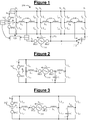
figure 1 est un schéma électrique d'une installation électrique mettant en oeuvre l'invention.Thefigure 1 is an electrical diagram of an electrical installation embodying the invention. -
La
figure 2 est un schéma électrique d'un chargeur de batterie de l'installation électrique de lafigure 1 , dans un premier mode de fonctionnement.Thefigure 2 is a circuit diagram of a battery charger the electrical installation of thefigure 1 in a first mode of operation. -
La
figure 3 est un schéma électrique d'un chargeur de batterie de l'installation électrique de lafigure 1 , dans un deuxième mode de fonctionnement.Thefigure 3 is a circuit diagram of a battery charger the electrical installation of thefigure 1 in a second mode of operation.
Sur les figures, les extrémités de chacun des composants électriques (inductances et capacité) discutés ci-dessous sont repérées respectivement par la marque « 1 » indiquant une première extrémité du composant électrique et la marque « 2 » indiquant une deuxième extrémité du composant électrique.In the figures, the ends of each of the electrical components (inductances and capacitance) discussed below are marked respectively by the mark "1" indicating a first end of the electrical component and the mark "2" indicating a second end of the electrical component.
En référence à la
Cette installation électrique 100 est par exemple destinée à être installée dans un véhicule automobile.This
L'installation électrique 100 comporte tout d'abord une batterie 102 présentant une borne négative et une borne positive et fournissant, entre ces bornes, une tension E continue.The
L'installation électrique 100 comporte en outre un moteur électrique présentant trois enroulements 104, 106, 108.The
L'installation électrique 100 comporte en outre un onduleur connectant la batterie 102 au moteur électrique.The
Plus précisément, l'onduleur comporte deux bornes BS1, BS2 connectées respectivement à la borne positive et à la borne négative de la batterie 102.More specifically, the inverter comprises two terminals BS1, BS2 respectively connected to the positive terminal and to the negative terminal of the
L'onduleur comporte en outre six bras de commutation BA...BF destinés à connecter respectivement les extrémités des enroulements 104, 106, 108 sélectivement à la borne BS1 et à la borne BS2. Par exemple, le bras de commutation BA est destiné à connecter une extrémité de l'enroulement 104 à la borne BS1 ou à la borne BS2, suivant son état.The inverter further comprises six switching arms B A ... B F for respectively connecting the ends of the
Chaque bras de commutation BA...BF comporte deux interrupteurs IA1 et IA2, ..., IF1 et IF2 connectés l'un à l'autre en un point milieu auquel est connectée l'extrémité de l'enroulement 104, 106, 108 associé à ce bras de commutation BA...BF. Les interrupteurs IA1 et IA2, .... IF1 et IF2 d'un même bras de commutation BA...BF sont en outre connectés respectivement à la borne BS1 et à la borne BS2. Par exemple, les interrupteurs IA1 et IA2 du bras de commutation BA sont connectés respectivement à la borne BS1 et à la borne BS2.Each switching arm B A ... B F comprises two switches I A1 and I A2 , ..., I F1 and I F2 connected to each other at a midpoint to which is connected the end of the winding 104, 106, 108 associated with this switching arm B A ... B F. The switches I A1 and I A2 , .... I F1 and I F2 of the same switching arm B A ... B F are further connected respectively to the terminal BS1 and the terminal BS2. For example, the switches I A1 and I A2 of the switching arm B A are respectively connected to the terminal BS1 and to the terminal BS2.
Ainsi, suivant la configuration des bras de commutation BA...BF, chaque enroulement 104, 106, 108 peut se voir appliquer une tension nulle (les deux extrémités de l'enroulement sont connectées à la même borne, négative ou positive, de la batterie 102), la tension +E ou la tension -E. Il est ainsi possible de faire varier les tensions moyennes appliquées aux enroulements pour faire tourner un rotor du moteur électrique. Le moteur électrique est par exemple destiné à entraîner des roues du véhicule automobile.Thus, according to the configuration of the switching arms B A ... B F , each winding 104, 106, 108 may be applied a zero voltage (the two ends of the winding are connected to the same terminal, negative or positive, of the battery 102), the voltage + E or the voltage -E. It is thus possible to vary the average voltages applied to the windings to rotate a rotor of the electric motor. The electric motor is for example intended to drive wheels of the motor vehicle.
L'installation électrique 100 comporte en outre un chargeur de batterie destiné à charger la batterie 104 à partir d'un réseau électrique 110, en fournissant un courant de charge iB à la batterie 102. Le réseau électrique 110 est par exemple un réseau monophasé ou bien un réseau polyphasé, par exemple triphasé. Dans ce deuxième cas, la borne BS2 est par exemple connectée au neutre du réseau électrique 110, tandis que la borne BS1 est connectée à l'une des phases du réseau électrique 110.The
Comme cela sera apparent par la suite, dans l'exemple décrit, le chargeur de batterie réutilise des éléments de l'onduleur et du moteur électrique.As will be apparent later, in the example described, the battery charger reuses elements of the inverter and the electric motor.
Ainsi, le chargeur de batterie comporte tout d'abord les bornes BS1, BS2, qualifiées de « bornes de sortie » dans le cadre du chargeur de batterie. Comme indiqué plus haut, les bornes de sortie BS1, BS2 sont connectées respectivement à la borne positive et à la borne négative de la batterie 102 pour fournir le courant de charge iB à la batterie 102.Thus, the battery charger first has terminals BS1, BS2, termed "output terminals" in the battery charger frame. As indicated above, the output terminals BS1, BS2 are respectively connected to the positive terminal and the negative terminal of the
Le chargeur de batterie 106 comporte en outre deux bornes d'entrée BE1, BE2 destinées à être connectées au réseau électrique 110 pour se voir appliquer une tension de réseau uR sinusoïdale. La connexion se fait par exemple au moyen d'une connectique (non représentée) permettant le raccordement à une prise du réseau électrique 110.The
Le chargeur de batterie 106 comporte en outre deux inductances LA, LC présentant des premières extrémités connectées respectivement à la borne d'entrée BE1 et à la borne d'entrée BE2. Dans l'exemple décrit, les inductances LA, LC comportent chacune au moins une partie de respectivement l'enroulement 104 et l'enroulement 106.The
Le chargeur de batterie 106 comporte en outre les deux bras de commutation BA, BC destinés à connecter respectivement des deuxièmes extrémités des inductances LA, LC sélectivement à la borne de sortie BS1 et à la borne de sortie BS2. Ainsi, le bras de commutation BA est destiné à connecter la borne d'entrée BE1 sélectivement à la borne de sortie BS1 et à la borne de sortie BS2, à chaque fois au travers de l'inductance LA. De manière similaire, le bras de commutation BC est destiné à connecter la borne d'entrée BE2 sélectivement à la borne de sortie BS1 et à la borne de sortie BS2, à chaque fois au travers de l'inductance LC.The
Le chargeur de batterie comporte en outre une inductance LE comportant au moins une partie de l'enroulement 108.The battery charger further comprises an inductor L E having at least a part of the winding 108.
Le chargeur de batterie comporte en outre le bras de commutation BE destiné à connecter une première extrémité de l'inductance LE sélectivement à la borne de sortie BS1 et à la borne de sortie BS2.The battery charger further includes the switching arm B E for connecting a first end of the inductor L E selectively to the output terminal BS1 and the output terminal BS2.
Le chargeur de batterie comporte en outre une capacité de lissage C présentant une première extrémité connectée à la borne de sortie BS2.The battery charger further comprises a smoothing capacitor C having a first end connected to the output terminal BS2.
Le chargeur de batterie comporte en outre un dispositif de connexion 112 destiné à connecter une deuxième extrémité de la capacité de lissage C au moins à la borne d'entrée BE2. Dans l'exemple décrit, le dispositif de connexion 112 est un commutateur 112 destiné à connecter la deuxième extrémité de la capacité de lissage C sélectivement à la borne d'entrée BE2 et à une deuxième extrémité de l'inductance LE.The battery charger further includes a
Lorsque le commutateur connecte la deuxième extrémité de la capacité de lissage C à la borne d'entrée BE2, le bras de commutation BC est destiné à de connecter la capacité de lissage C sélectivement à la borne de sortie BS1 et à la borne de sortie BS2, à chaque fois au travers de l'inductance LC. Lorsque le commutateur 112 connecte la deuxième extrémité de la capacité de lissage C à la deuxième extrémité de l'inductance LE, le bras de commutation BE est destiné à de connecter la capacité de lissage C sélectivement à la borne de sortie BS1 et à la borne de sortie BS2, à chaque fois au travers de l'inductance LE.When the switch connects the second end of the smoothing capacitor C to the input terminal BE2, the switching arm B C is intended to connect the smoothing capacitance C selectively to the output terminal BS1 and to the output terminal BS2, each time through the inductor L C. When the
Le chargeur de batterie comporte en outre un dispositif 114 de mesure du courant de réseau iR, un dispositif 116 de mesure du courant de charge iB et un dispositif 118 de mesure de la tension de batterie E.The battery charger further comprises a
Le chargeur de batterie 106 comporte en outre un dispositif de commande 120 destiné à commander les bras de commutation BA, BC, BE et le commutateur 112, à partir des mesures des dispositifs de mesure 114, 116, 118.The
Plus précisément, le chargeur de batterie est destiné à fonctionner alternativement dans deux modes de fonctionnement.More specifically, the battery charger is intended to operate alternately in two modes of operation.
Lorsque la tension de batterie E mesurée est supérieure à un seuil, le dispositif de commande 120 fait passer le chargeur de batterie dans un premier mode de fonctionnement. Le schéma électrique du chargeur de batterie dans le premier mode de fonctionnement est illustré sur la
Dans le premier mode de fonctionnement, le dispositif de commande 120 commande au commutateur 112 de connecter la deuxième extrémité de la capacité de lissage C à la borne d'entrée BE2.In the first mode of operation, the
Le dispositif de commande 120 commande en outre les bras de commutation BA, BC en fonction du courant de réseau iR mesuré, de manière à prélever du réseau électrique 110 un courant de réseau iR en phase avec la tension de réseau uR. Ainsi, le facteur de puissance du chargeur de batterie est augmenté pour qu'il s'approche de 1.The
Le dispositif de commande 120 commande en outre au moins le bras de commutation BC (et de préférence les deux bras de commutation BA, BC) en fonction du courant de charge iB mesuré, de manière à alternativement charger et décharger la capacité de lissage C pour lisser le courant de charge iB. La capacité de lissage C est traversée par un courant de lissage iC qui, lors de la charge de la capacité de lissage C, vient réduire le courant de charge iB, et lors de la décharge de la capacité de lissage C, vient augmenter le courant de charge iB.The
Il sera apprécié que le bras de commutation BE n'est pas utilisé dans le premier mode de fonctionnement. Seuls les deux bras de commutation BA, BC sont utilisés pour corriger le facteur de puissance et pour lisser le courant de charge iB. Cela limite le nombre d'interrupteurs, et donc les pertes dues aux commutations, ainsi que le nombre d'inductances, et donc les pertes fers.It will be appreciated that the switching arm B E is not used in the first mode of operation. Only the two switching arms B A , B C are used to correct the power factor and to smooth the charging current i B. This limits the number of switches, and therefore the losses due to switching, as well as the number of inductances, and thus the irons losses.
Le lissage du courant de charge iB permet de réduire les oscillations apparaissant à deux fois la fréquence du réseau électrique 110. Par exemple, avec une fréquence du réseau électrique 110 valant 50 ou 60 Hz, les oscillations de courant de charge iB auraient une fréquence de 100 ou 120 Hz, respectivement.The smoothing of the charging current i B makes it possible to reduce the oscillations appearing at twice the frequency of the
Lorsque la tension de batterie E mesurée est inférieure au seuil, le dispositif de commande 120 fait passer le chargeur de batterie dans un deuxième mode de fonctionnement. Le schéma électrique du chargeur de batterie dans le deuxième mode de fonctionnement est illustré sur la
Dans le deuxième mode de fonctionnement, le dispositif de commande 120 commande au commutateur 112 de connecter la deuxième extrémité de la capacité de lissage C à la deuxième extrémité de l'inductance LE.In the second mode of operation, the
Le dispositif de commande 120 commande toujours les bras de commutation BA, BC en fonction du courant de réseau iR mesuré, de manière à prélever du réseau électrique 110 un courant de réseau iR en phase avec la tension de réseau uR.The
Cependant, cette fois, c'est le bras de commutation BE que le dispositif de commande 120 commande en fonction du courant de charge iB mesuré, de manière à alternativement charger et décharger la capacité de lissage C pour lisser le courant de charge iB.However, this time it is the switching arm B E that the
De préférence, le seuil est supérieur ou égal à deux fois la tension crête (c'est-à-dire la valeur maximale) du réseau électrique 110. Le seuil est par exemple égal à deux fois la tension crête théorique plus 10%. En effet, lorsque le chargeur de batterie est dans le premier mode de fonctionnement (
Le seuil permettant de basculer d'un mode de fonctionnement à l'autre est par exemple un seuil fixe prédéterminé.The threshold for switching from one operating mode to another is for example a predetermined fixed threshold.
Alternativement, le seuil dépend de la tension du réseau. Dans ce cas, par exemple, l'installation électrique 100 comporte en outre un dispositif de mesure de l'amplitude de la tension de réseau uR, par exemple la tension de réseau crête-à-crête. Le dispositif de commande 120 est alors destiné à déterminer le seuil à partir de la mesure. En particulier, le dispositif de commande 120 est destiné à déterminer un seuil d'autant plus élevé que l'amplitude de la tension de réseau est élevée.Alternatively, the threshold depends on the voltage of the network. In this case, for example, the
La présente invention n'est pas limitée au mode de réalisation décrit précédemment, mais est au contraire définie par les revendications qui suivent. Il sera en effet apparent à l'homme du métier que des modifications peuvent y être apportées.The present invention is not limited to the embodiment described above, but is instead defined by the following claims. It will be apparent to those skilled in the art that modifications can be made.
En particulier, le chargeur de batterie pourrait être conçu pour fonctionner uniquement dans le premier mode de fonctionnement, par exemple s'il est jugé que le risque de décharge de la batterie E est très faible. Dans ce cas, le dispositif de connexion 112 pourrait être un simple connecteur électrique connectant la capacité de lissage C à la borne d'entrée BE2. Dans ce cas toujours, le bras de commutation BE ne serait pas utilisé.In particular, the battery charger could be designed to operate only in the first mode of operation, for example if it is judged that the risk of discharging the battery E is very low. In this case, the
Par ailleurs, les termes utilisés dans les revendications ne doivent pas être compris comme limités aux éléments du mode de réalisation décrit précédemment, mais doivent au contraire être compris comme couvrant tous les éléments équivalents que l'homme du métier peut déduire à partir de ses connaissances générales.Moreover, the terms used in the claims should not be understood as limited to the elements of the embodiment described above, but should instead be understood as covering all the equivalent elements that a person skilled in the art can deduce from his knowledge. General.
- Installation électriqueElectrical Installation
- 100100
- BatterieDrums
- 102102
- Premier enroulementFirst winding
- 104104
- Deuxième enroulementSecond winding
- 106106
- Troisième enroulementThird winding
- 108108
- Réseau électriqueElectrical network
- 110110
- Dispositif de connexion (commutateur)Connection device (switch)
- 112112
- Dispositif de mesure du courant de réseauNetwork current measuring device
- 114114
- Dispositif de mesure du courant de chargeLoad current measuring device
- 116116
- Dispositif de mesure de la tension de batterieDevice for measuring the battery voltage
- 118118
- Dispositif de commandeControl device
- 120120
- Capacité de lissageSmoothing ability
- CVS
- Courant de lissageSmoothing current
- iC i C
- Tension de réseauNetwork voltage
- uR u R
- Courant de réseauNetwork current
- iR i R
- Tension de batterieBattery voltage
- EE
- Courant de chargeCharge current
- iB i B
- Bras de commutationSwitching arm
- BA...BF B A ... B F
- Interrupteursswitches
- IA1,IA2, ..., IF1, IF2 I A1 , I A2 , ..., I F1 , I F2
Claims (10)
et dans lequel, lorsque la deuxième extrémité de la capacité de lissage (C) est connectée à la deuxième extrémité de la troisième inductance (LE), le dispositif de commande (120) est destiné à commander le troisième bras de commutation (BE) de manière à alternativement charger et décharger la capacité de lissage (C) pour lisser le courant de charge (iB).A battery charger according to claim 1 or 2, further comprising:
and wherein, when the second end of the smoothing capacitance (C) is connected to the second end of the third inductor (L E ), the controller (120) is for controlling the third switching arm (B E ) to alternately load and unload the smoothing capacitance (C) to smooth the charging current (i B ).
Applications Claiming Priority (1)
| Application Number | Priority Date | Filing Date | Title |
|---|---|---|---|
| FR1553312A FR3035282B1 (en) | 2015-04-15 | 2015-04-15 | BATTERY CHARGER, ELECTRICAL INSTALLATION AND MOTOR VEHICLE |
Publications (3)
| Publication Number | Publication Date |
|---|---|
| EP3082241A2 true EP3082241A2 (en) | 2016-10-19 |
| EP3082241A3 EP3082241A3 (en) | 2017-01-11 |
| EP3082241B1 EP3082241B1 (en) | 2020-07-29 |
Family
ID=54199753
Family Applications (1)
| Application Number | Title | Priority Date | Filing Date |
|---|---|---|---|
| EP16164789.6A Active EP3082241B1 (en) | 2015-04-15 | 2016-04-12 | Battery charger, electrical installation and motor vehicle |
Country Status (3)
| Country | Link |
|---|---|
| US (1) | US9937807B2 (en) |
| EP (1) | EP3082241B1 (en) |
| FR (1) | FR3035282B1 (en) |
Families Citing this family (1)
| Publication number | Priority date | Publication date | Assignee | Title |
|---|---|---|---|---|
| CN109552086B (en) * | 2018-12-18 | 2024-03-19 | 深圳市信维通信股份有限公司 | Wireless charging system of electric automobile and control method thereof |
Citations (1)
| Publication number | Priority date | Publication date | Assignee | Title |
|---|---|---|---|---|
| FR2991833A1 (en) | 2012-06-06 | 2013-12-13 | Valeo Sys Controle Moteur Sas | ABSORPTION CIRCUIT FOR POWER RIPPING ASSOCIATED METHOD |
Family Cites Families (9)
| Publication number | Priority date | Publication date | Assignee | Title |
|---|---|---|---|---|
| JP2005102476A (en) * | 2003-08-29 | 2005-04-14 | Fuji Electric Systems Co Ltd | Activation method for power conversion device |
| CN101685969B (en) * | 2008-09-25 | 2012-10-10 | 艾默生网络能源系统北美公司 | Control method of multipath non-bridge PFC circuits |
| JP4880762B2 (en) * | 2008-09-26 | 2012-02-22 | 株式会社MERSTech | Power converter |
| JP4764499B2 (en) * | 2009-08-05 | 2011-09-07 | 本田技研工業株式会社 | DC / DC converter and power supply system including the DC / DC converter |
| US8324863B2 (en) * | 2010-04-19 | 2012-12-04 | Tesla Motors, Inc. | Trickle charger for high-energy storage systems |
| US8810206B2 (en) * | 2010-07-22 | 2014-08-19 | Toyota Jidosha Kabushiki Kaisha | Electric motored vehicle and method for controlling electrically charging the same |
| WO2012160660A1 (en) * | 2011-05-25 | 2012-11-29 | 株式会社日立製作所 | Charging system |
| CN103597725B (en) * | 2012-06-01 | 2015-02-18 | 松下电器产业株式会社 | Power conversion device and battery charging device using same |
| KR101558662B1 (en) * | 2013-10-10 | 2015-10-08 | 현대자동차주식회사 | Switching power supply device and battery charger including the same |
-
2015
- 2015-04-15 FR FR1553312A patent/FR3035282B1/en active Active
-
2016
- 2016-04-12 EP EP16164789.6A patent/EP3082241B1/en active Active
- 2016-04-15 US US15/099,983 patent/US9937807B2/en active Active
Patent Citations (1)
| Publication number | Priority date | Publication date | Assignee | Title |
|---|---|---|---|---|
| FR2991833A1 (en) | 2012-06-06 | 2013-12-13 | Valeo Sys Controle Moteur Sas | ABSORPTION CIRCUIT FOR POWER RIPPING ASSOCIATED METHOD |
Also Published As
| Publication number | Publication date |
|---|---|
| US9937807B2 (en) | 2018-04-10 |
| EP3082241A3 (en) | 2017-01-11 |
| FR3035282A1 (en) | 2016-10-21 |
| US20160303982A1 (en) | 2016-10-20 |
| EP3082241B1 (en) | 2020-07-29 |
| FR3035282B1 (en) | 2018-05-11 |
Similar Documents
| Publication | Publication Date | Title |
|---|---|---|
| EP2695279B1 (en) | Charge transfer device and associated management method | |
| EP2352661B1 (en) | Interconnection housing for motor vehicle | |
| EP2660095B1 (en) | Converter stage, electrical converter comprising such a converter stage, ac/dc converter comprising such a converter, and battery charching terminal comprising such a converter or converter stage | |
| EP2677645B1 (en) | System for powering a load, comprising a converter connected to a network and a transformer connected in parallel to the converter to limit the zero sequence current, and drive chain comprising such a system | |
| EP3607644A1 (en) | Method for controlling a charging device on board an electric or hybrid vehicle | |
| EP2794343B1 (en) | Method of exchanging electrical energy between an electrical network conveying a dc or ac electrical quantity and an electrical energy storage unit for hybrid or electric vehicle | |
| EP3183795B1 (en) | Battery charger for high-integration electric or hybrid motor vehicle | |
| EP3082241B1 (en) | Battery charger, electrical installation and motor vehicle | |
| EP3171505B1 (en) | Device for charging a traction battery of a motor vehicle with at least partially electric traction | |
| EP3682525A1 (en) | Vehicle charger comprising a dc/dc converter | |
| FR3065332B1 (en) | CONVERTING DEVICE, CONTROL METHOD AND VEHICLE THEREFOR | |
| FR3005378A1 (en) | SYSTEM AND METHOD FOR CHARGING THE BATTERY OF AN ELECTRIC OR HYBRID VEHICLE | |
| EP3053247B1 (en) | System and method for charging a traction battery limiting the current draw of parasitic capacitances | |
| FR3040494B1 (en) | ELECTRICAL SYSTEM COMPRISING A DEVICE FOR EVALUATING AN INSULATION FAULT, A MOTOR VEHICLE COMPRISING SUCH AN ELECTRICAL SYSTEM AND A METHOD OF EVALUATING AN INSULATION FAULT | |
| EP3681756B1 (en) | Vehicle charger comprising a dc-to-dc converter | |
| KR20200116585A (en) | System and method for vehicle start using solar cell | |
| WO2019110297A1 (en) | Dc-dc converter with pre-charging of a first electrical grid from a second electrical grid | |
| EP3539203B1 (en) | Method for controlling a three-phase rectifier for a charging device on board an electrical or hybrid vehicle | |
| EP3086437B1 (en) | Battery charger, electrical system including such a charger, electric vehicle including such a system | |
| FR2926684A1 (en) | Power supply system for hybrid motor vehicle, has energy exchange device provided for permitting power transfer between energy storage unit, power storage unit, energy consuming equipment and energy providing equipment | |
| FR2998115A1 (en) | Electric conversion stage for electric converter of electric battery recharging terminal of car, has capacitor connected between output terminals, and electromagnetic coil connected between one of terminals and midpoint of switching branch | |
| WO2023110539A1 (en) | Electric device with capacitive galvanic isolation | |
| FR2521366A1 (en) | VARIABLE ELECTRICAL ENERGY STABILIZER | |
| FR2983365A1 (en) | Power supply system for supplying power to battery of electric car, has transistor modulating current intensity of inductor coil so that average value of modulated current intensity is equal to value of reference current | |
| FR2974462A1 (en) | Device for charging storage unit i.e. rechargeable high voltage battery, for electric vehicle, has power factor correction module connected to connection terminals and power supply during charging phase of storage unit |
Legal Events
| Date | Code | Title | Description |
|---|---|---|---|
| PUAI | Public reference made under article 153(3) epc to a published international application that has entered the european phase |
Free format text: ORIGINAL CODE: 0009012 |
|
| 17P | Request for examination filed |
Effective date: 20160412 |
|
| AK | Designated contracting states |
Kind code of ref document: A2 Designated state(s): AL AT BE BG CH CY CZ DE DK EE ES FI FR GB GR HR HU IE IS IT LI LT LU LV MC MK MT NL NO PL PT RO RS SE SI SK SM TR |
|
| AX | Request for extension of the european patent |
Extension state: BA ME |
|
| PUAL | Search report despatched |
Free format text: ORIGINAL CODE: 0009013 |
|
| AK | Designated contracting states |
Kind code of ref document: A3 Designated state(s): AL AT BE BG CH CY CZ DE DK EE ES FI FR GB GR HR HU IE IS IT LI LT LU LV MC MK MT NL NO PL PT RO RS SE SI SK SM TR |
|
| AX | Request for extension of the european patent |
Extension state: BA ME |
|
| RIC1 | Information provided on ipc code assigned before grant |
Ipc: H02M 1/42 20070101ALI20161208BHEP Ipc: B60L 11/18 20060101ALI20161208BHEP Ipc: H02M 1/15 20060101AFI20161208BHEP |
|
| RIN1 | Information on inventor provided before grant (corrected) |
Inventor name: CHAUVENET, PIERRE-ALEXANDRE Inventor name: SILVESTRE, BENEDICTE Inventor name: CONDAMIN, BRUNO Inventor name: BOUCHEZ, BORIS Inventor name: DE SOUSA, LUIS |
|
| STAA | Information on the status of an ep patent application or granted ep patent |
Free format text: STATUS: REQUEST FOR EXAMINATION WAS MADE |
|
| RAP1 | Party data changed (applicant data changed or rights of an application transferred) |
Owner name: VALEO SIEMENS EAUTOMOTIVE FRANCE SAS |
|
| GRAP | Despatch of communication of intention to grant a patent |
Free format text: ORIGINAL CODE: EPIDOSNIGR1 |
|
| STAA | Information on the status of an ep patent application or granted ep patent |
Free format text: STATUS: GRANT OF PATENT IS INTENDED |
|
| RIC1 | Information provided on ipc code assigned before grant |
Ipc: H02M 1/42 20070101ALI20200207BHEP Ipc: H02M 1/15 20060101AFI20200207BHEP |
|
| INTG | Intention to grant announced |
Effective date: 20200303 |
|
| RIN1 | Information on inventor provided before grant (corrected) |
Inventor name: CONDAMIN, BRUNO Inventor name: BOUCHEZ, BORIS Inventor name: CHAUVENET, PIERRE-ALEXANDRE Inventor name: DE SOUSA, LUIS Inventor name: SILVESTRE, BENEDICTE |
|
| GRAS | Grant fee paid |
Free format text: ORIGINAL CODE: EPIDOSNIGR3 |
|
| GRAA | (expected) grant |
Free format text: ORIGINAL CODE: 0009210 |
|
| STAA | Information on the status of an ep patent application or granted ep patent |
Free format text: STATUS: THE PATENT HAS BEEN GRANTED |
|
| AK | Designated contracting states |
Kind code of ref document: B1 Designated state(s): AL AT BE BG CH CY CZ DE DK EE ES FI FR GB GR HR HU IE IS IT LI LT LU LV MC MK MT NL NO PL PT RO RS SE SI SK SM TR |
|
| REG | Reference to a national code |
Ref country code: CH Ref legal event code: EP |
|
| REG | Reference to a national code |
Ref country code: AT Ref legal event code: REF Ref document number: 1296946 Country of ref document: AT Kind code of ref document: T Effective date: 20200815 |
|
| REG | Reference to a national code |
Ref country code: IE Ref legal event code: FG4D Free format text: LANGUAGE OF EP DOCUMENT: FRENCH |
|
| REG | Reference to a national code |
Ref country code: DE Ref legal event code: R096 Ref document number: 602016040671 Country of ref document: DE |
|
| REG | Reference to a national code |
Ref country code: LT Ref legal event code: MG4D |
|
| REG | Reference to a national code |
Ref country code: NL Ref legal event code: MP Effective date: 20200729 |
|
| REG | Reference to a national code |
Ref country code: AT Ref legal event code: MK05 Ref document number: 1296946 Country of ref document: AT Kind code of ref document: T Effective date: 20200729 |
|
| PG25 | Lapsed in a contracting state [announced via postgrant information from national office to epo] |
Ref country code: ES Free format text: LAPSE BECAUSE OF FAILURE TO SUBMIT A TRANSLATION OF THE DESCRIPTION OR TO PAY THE FEE WITHIN THE PRESCRIBED TIME-LIMIT Effective date: 20200729 Ref country code: NO Free format text: LAPSE BECAUSE OF FAILURE TO SUBMIT A TRANSLATION OF THE DESCRIPTION OR TO PAY THE FEE WITHIN THE PRESCRIBED TIME-LIMIT Effective date: 20201029 Ref country code: BG Free format text: LAPSE BECAUSE OF FAILURE TO SUBMIT A TRANSLATION OF THE DESCRIPTION OR TO PAY THE FEE WITHIN THE PRESCRIBED TIME-LIMIT Effective date: 20201029 Ref country code: AT Free format text: LAPSE BECAUSE OF FAILURE TO SUBMIT A TRANSLATION OF THE DESCRIPTION OR TO PAY THE FEE WITHIN THE PRESCRIBED TIME-LIMIT Effective date: 20200729 Ref country code: FI Free format text: LAPSE BECAUSE OF FAILURE TO SUBMIT A TRANSLATION OF THE DESCRIPTION OR TO PAY THE FEE WITHIN THE PRESCRIBED TIME-LIMIT Effective date: 20200729 Ref country code: GR Free format text: LAPSE BECAUSE OF FAILURE TO SUBMIT A TRANSLATION OF THE DESCRIPTION OR TO PAY THE FEE WITHIN THE PRESCRIBED TIME-LIMIT Effective date: 20201030 Ref country code: LT Free format text: LAPSE BECAUSE OF FAILURE TO SUBMIT A TRANSLATION OF THE DESCRIPTION OR TO PAY THE FEE WITHIN THE PRESCRIBED TIME-LIMIT Effective date: 20200729 Ref country code: HR Free format text: LAPSE BECAUSE OF FAILURE TO SUBMIT A TRANSLATION OF THE DESCRIPTION OR TO PAY THE FEE WITHIN THE PRESCRIBED TIME-LIMIT Effective date: 20200729 Ref country code: SE Free format text: LAPSE BECAUSE OF FAILURE TO SUBMIT A TRANSLATION OF THE DESCRIPTION OR TO PAY THE FEE WITHIN THE PRESCRIBED TIME-LIMIT Effective date: 20200729 Ref country code: PT Free format text: LAPSE BECAUSE OF FAILURE TO SUBMIT A TRANSLATION OF THE DESCRIPTION OR TO PAY THE FEE WITHIN THE PRESCRIBED TIME-LIMIT Effective date: 20201130 |
|
| PG25 | Lapsed in a contracting state [announced via postgrant information from national office to epo] |
Ref country code: LV Free format text: LAPSE BECAUSE OF FAILURE TO SUBMIT A TRANSLATION OF THE DESCRIPTION OR TO PAY THE FEE WITHIN THE PRESCRIBED TIME-LIMIT Effective date: 20200729 Ref country code: RS Free format text: LAPSE BECAUSE OF FAILURE TO SUBMIT A TRANSLATION OF THE DESCRIPTION OR TO PAY THE FEE WITHIN THE PRESCRIBED TIME-LIMIT Effective date: 20200729 Ref country code: PL Free format text: LAPSE BECAUSE OF FAILURE TO SUBMIT A TRANSLATION OF THE DESCRIPTION OR TO PAY THE FEE WITHIN THE PRESCRIBED TIME-LIMIT Effective date: 20200729 Ref country code: IS Free format text: LAPSE BECAUSE OF FAILURE TO SUBMIT A TRANSLATION OF THE DESCRIPTION OR TO PAY THE FEE WITHIN THE PRESCRIBED TIME-LIMIT Effective date: 20201129 |
|
| PG25 | Lapsed in a contracting state [announced via postgrant information from national office to epo] |
Ref country code: NL Free format text: LAPSE BECAUSE OF FAILURE TO SUBMIT A TRANSLATION OF THE DESCRIPTION OR TO PAY THE FEE WITHIN THE PRESCRIBED TIME-LIMIT Effective date: 20200729 |
|
| PG25 | Lapsed in a contracting state [announced via postgrant information from national office to epo] |
Ref country code: EE Free format text: LAPSE BECAUSE OF FAILURE TO SUBMIT A TRANSLATION OF THE DESCRIPTION OR TO PAY THE FEE WITHIN THE PRESCRIBED TIME-LIMIT Effective date: 20200729 Ref country code: SM Free format text: LAPSE BECAUSE OF FAILURE TO SUBMIT A TRANSLATION OF THE DESCRIPTION OR TO PAY THE FEE WITHIN THE PRESCRIBED TIME-LIMIT Effective date: 20200729 Ref country code: RO Free format text: LAPSE BECAUSE OF FAILURE TO SUBMIT A TRANSLATION OF THE DESCRIPTION OR TO PAY THE FEE WITHIN THE PRESCRIBED TIME-LIMIT Effective date: 20200729 Ref country code: DK Free format text: LAPSE BECAUSE OF FAILURE TO SUBMIT A TRANSLATION OF THE DESCRIPTION OR TO PAY THE FEE WITHIN THE PRESCRIBED TIME-LIMIT Effective date: 20200729 Ref country code: CZ Free format text: LAPSE BECAUSE OF FAILURE TO SUBMIT A TRANSLATION OF THE DESCRIPTION OR TO PAY THE FEE WITHIN THE PRESCRIBED TIME-LIMIT Effective date: 20200729 Ref country code: IT Free format text: LAPSE BECAUSE OF FAILURE TO SUBMIT A TRANSLATION OF THE DESCRIPTION OR TO PAY THE FEE WITHIN THE PRESCRIBED TIME-LIMIT Effective date: 20200729 |
|
| REG | Reference to a national code |
Ref country code: DE Ref legal event code: R097 Ref document number: 602016040671 Country of ref document: DE |
|
| PG25 | Lapsed in a contracting state [announced via postgrant information from national office to epo] |
Ref country code: AL Free format text: LAPSE BECAUSE OF FAILURE TO SUBMIT A TRANSLATION OF THE DESCRIPTION OR TO PAY THE FEE WITHIN THE PRESCRIBED TIME-LIMIT Effective date: 20200729 |
|
| PLBE | No opposition filed within time limit |
Free format text: ORIGINAL CODE: 0009261 |
|
| STAA | Information on the status of an ep patent application or granted ep patent |
Free format text: STATUS: NO OPPOSITION FILED WITHIN TIME LIMIT |
|
| PG25 | Lapsed in a contracting state [announced via postgrant information from national office to epo] |
Ref country code: SK Free format text: LAPSE BECAUSE OF FAILURE TO SUBMIT A TRANSLATION OF THE DESCRIPTION OR TO PAY THE FEE WITHIN THE PRESCRIBED TIME-LIMIT Effective date: 20200729 |
|
| 26N | No opposition filed |
Effective date: 20210430 |
|
| PG25 | Lapsed in a contracting state [announced via postgrant information from national office to epo] |
Ref country code: SI Free format text: LAPSE BECAUSE OF FAILURE TO SUBMIT A TRANSLATION OF THE DESCRIPTION OR TO PAY THE FEE WITHIN THE PRESCRIBED TIME-LIMIT Effective date: 20200729 |
|
| PG25 | Lapsed in a contracting state [announced via postgrant information from national office to epo] |
Ref country code: MC Free format text: LAPSE BECAUSE OF FAILURE TO SUBMIT A TRANSLATION OF THE DESCRIPTION OR TO PAY THE FEE WITHIN THE PRESCRIBED TIME-LIMIT Effective date: 20200729 |
|
| PG25 | Lapsed in a contracting state [announced via postgrant information from national office to epo] |
Ref country code: LU Free format text: LAPSE BECAUSE OF NON-PAYMENT OF DUE FEES Effective date: 20210412 |
|
| REG | Reference to a national code |
Ref country code: BE Ref legal event code: MM Effective date: 20210430 |
|
| PG25 | Lapsed in a contracting state [announced via postgrant information from national office to epo] |
Ref country code: LI Free format text: LAPSE BECAUSE OF NON-PAYMENT OF DUE FEES Effective date: 20210430 Ref country code: CH Free format text: LAPSE BECAUSE OF NON-PAYMENT OF DUE FEES Effective date: 20210430 |
|
| PG25 | Lapsed in a contracting state [announced via postgrant information from national office to epo] |
Ref country code: IE Free format text: LAPSE BECAUSE OF NON-PAYMENT OF DUE FEES Effective date: 20210412 |
|
| PG25 | Lapsed in a contracting state [announced via postgrant information from national office to epo] |
Ref country code: IS Free format text: LAPSE BECAUSE OF FAILURE TO SUBMIT A TRANSLATION OF THE DESCRIPTION OR TO PAY THE FEE WITHIN THE PRESCRIBED TIME-LIMIT Effective date: 20201129 |
|
| PG25 | Lapsed in a contracting state [announced via postgrant information from national office to epo] |
Ref country code: BE Free format text: LAPSE BECAUSE OF NON-PAYMENT OF DUE FEES Effective date: 20210430 |
|
| PG25 | Lapsed in a contracting state [announced via postgrant information from national office to epo] |
Ref country code: HU Free format text: LAPSE BECAUSE OF FAILURE TO SUBMIT A TRANSLATION OF THE DESCRIPTION OR TO PAY THE FEE WITHIN THE PRESCRIBED TIME-LIMIT; INVALID AB INITIO Effective date: 20160412 |
|
| PG25 | Lapsed in a contracting state [announced via postgrant information from national office to epo] |
Ref country code: CY Free format text: LAPSE BECAUSE OF FAILURE TO SUBMIT A TRANSLATION OF THE DESCRIPTION OR TO PAY THE FEE WITHIN THE PRESCRIBED TIME-LIMIT Effective date: 20200729 |
|
| PGFP | Annual fee paid to national office [announced via postgrant information from national office to epo] |
Ref country code: FR Payment date: 20230425 Year of fee payment: 8 Ref country code: DE Payment date: 20230412 Year of fee payment: 8 |
|
| P01 | Opt-out of the competence of the unified patent court (upc) registered |
Effective date: 20230629 |
|
| PGFP | Annual fee paid to national office [announced via postgrant information from national office to epo] |
Ref country code: GB Payment date: 20230424 Year of fee payment: 8 |
|
| PG25 | Lapsed in a contracting state [announced via postgrant information from national office to epo] |
Ref country code: MK Free format text: LAPSE BECAUSE OF FAILURE TO SUBMIT A TRANSLATION OF THE DESCRIPTION OR TO PAY THE FEE WITHIN THE PRESCRIBED TIME-LIMIT Effective date: 20200729 |