EP3082175A1 - Battery, battery case and electronic vehicle - Google Patents
Battery, battery case and electronic vehicle Download PDFInfo
- Publication number
- EP3082175A1 EP3082175A1 EP16162698.1A EP16162698A EP3082175A1 EP 3082175 A1 EP3082175 A1 EP 3082175A1 EP 16162698 A EP16162698 A EP 16162698A EP 3082175 A1 EP3082175 A1 EP 3082175A1
- Authority
- EP
- European Patent Office
- Prior art keywords
- accommodating portion
- battery
- partition wall
- cell accommodating
- battery cells
- Prior art date
- Legal status (The legal status is an assumption and is not a legal conclusion. Google has not performed a legal analysis and makes no representation as to the accuracy of the status listed.)
- Granted
Links
Images


Classifications
-
- H—ELECTRICITY
- H01—ELECTRIC ELEMENTS
- H01M—PROCESSES OR MEANS, e.g. BATTERIES, FOR THE DIRECT CONVERSION OF CHEMICAL ENERGY INTO ELECTRICAL ENERGY
- H01M10/00—Secondary cells; Manufacture thereof
- H01M10/42—Methods or arrangements for servicing or maintenance of secondary cells or secondary half-cells
- H01M10/425—Structural combination with electronic components, e.g. electronic circuits integrated to the outside of the casing
-
- H—ELECTRICITY
- H01—ELECTRIC ELEMENTS
- H01M—PROCESSES OR MEANS, e.g. BATTERIES, FOR THE DIRECT CONVERSION OF CHEMICAL ENERGY INTO ELECTRICAL ENERGY
- H01M10/00—Secondary cells; Manufacture thereof
- H01M10/05—Accumulators with non-aqueous electrolyte
- H01M10/058—Construction or manufacture
- H01M10/0585—Construction or manufacture of accumulators having only flat construction elements, i.e. flat positive electrodes, flat negative electrodes and flat separators
-
- B—PERFORMING OPERATIONS; TRANSPORTING
- B60—VEHICLES IN GENERAL
- B60L—PROPULSION OF ELECTRICALLY-PROPELLED VEHICLES; SUPPLYING ELECTRIC POWER FOR AUXILIARY EQUIPMENT OF ELECTRICALLY-PROPELLED VEHICLES; ELECTRODYNAMIC BRAKE SYSTEMS FOR VEHICLES IN GENERAL; MAGNETIC SUSPENSION OR LEVITATION FOR VEHICLES; MONITORING OPERATING VARIABLES OF ELECTRICALLY-PROPELLED VEHICLES; ELECTRIC SAFETY DEVICES FOR ELECTRICALLY-PROPELLED VEHICLES
- B60L50/00—Electric propulsion with power supplied within the vehicle
- B60L50/20—Electric propulsion with power supplied within the vehicle using propulsion power generated by humans or animals
-
- B—PERFORMING OPERATIONS; TRANSPORTING
- B60—VEHICLES IN GENERAL
- B60L—PROPULSION OF ELECTRICALLY-PROPELLED VEHICLES; SUPPLYING ELECTRIC POWER FOR AUXILIARY EQUIPMENT OF ELECTRICALLY-PROPELLED VEHICLES; ELECTRODYNAMIC BRAKE SYSTEMS FOR VEHICLES IN GENERAL; MAGNETIC SUSPENSION OR LEVITATION FOR VEHICLES; MONITORING OPERATING VARIABLES OF ELECTRICALLY-PROPELLED VEHICLES; ELECTRIC SAFETY DEVICES FOR ELECTRICALLY-PROPELLED VEHICLES
- B60L50/00—Electric propulsion with power supplied within the vehicle
- B60L50/50—Electric propulsion with power supplied within the vehicle using propulsion power supplied by batteries or fuel cells
- B60L50/60—Electric propulsion with power supplied within the vehicle using propulsion power supplied by batteries or fuel cells using power supplied by batteries
- B60L50/64—Constructional details of batteries specially adapted for electric vehicles
-
- B—PERFORMING OPERATIONS; TRANSPORTING
- B60—VEHICLES IN GENERAL
- B60L—PROPULSION OF ELECTRICALLY-PROPELLED VEHICLES; SUPPLYING ELECTRIC POWER FOR AUXILIARY EQUIPMENT OF ELECTRICALLY-PROPELLED VEHICLES; ELECTRODYNAMIC BRAKE SYSTEMS FOR VEHICLES IN GENERAL; MAGNETIC SUSPENSION OR LEVITATION FOR VEHICLES; MONITORING OPERATING VARIABLES OF ELECTRICALLY-PROPELLED VEHICLES; ELECTRIC SAFETY DEVICES FOR ELECTRICALLY-PROPELLED VEHICLES
- B60L50/00—Electric propulsion with power supplied within the vehicle
- B60L50/50—Electric propulsion with power supplied within the vehicle using propulsion power supplied by batteries or fuel cells
- B60L50/60—Electric propulsion with power supplied within the vehicle using propulsion power supplied by batteries or fuel cells using power supplied by batteries
- B60L50/66—Arrangements of batteries
-
- H—ELECTRICITY
- H01—ELECTRIC ELEMENTS
- H01M—PROCESSES OR MEANS, e.g. BATTERIES, FOR THE DIRECT CONVERSION OF CHEMICAL ENERGY INTO ELECTRICAL ENERGY
- H01M10/00—Secondary cells; Manufacture thereof
- H01M10/05—Accumulators with non-aqueous electrolyte
- H01M10/052—Li-accumulators
- H01M10/0525—Rocking-chair batteries, i.e. batteries with lithium insertion or intercalation in both electrodes; Lithium-ion batteries
-
- H—ELECTRICITY
- H01—ELECTRIC ELEMENTS
- H01M—PROCESSES OR MEANS, e.g. BATTERIES, FOR THE DIRECT CONVERSION OF CHEMICAL ENERGY INTO ELECTRICAL ENERGY
- H01M10/00—Secondary cells; Manufacture thereof
- H01M10/42—Methods or arrangements for servicing or maintenance of secondary cells or secondary half-cells
- H01M10/425—Structural combination with electronic components, e.g. electronic circuits integrated to the outside of the casing
- H01M10/4257—Smart batteries, e.g. electronic circuits inside the housing of the cells or batteries
-
- H—ELECTRICITY
- H01—ELECTRIC ELEMENTS
- H01M—PROCESSES OR MEANS, e.g. BATTERIES, FOR THE DIRECT CONVERSION OF CHEMICAL ENERGY INTO ELECTRICAL ENERGY
- H01M50/00—Constructional details or processes of manufacture of the non-active parts of electrochemical cells other than fuel cells, e.g. hybrid cells
- H01M50/20—Mountings; Secondary casings or frames; Racks, modules or packs; Suspension devices; Shock absorbers; Transport or carrying devices; Holders
- H01M50/204—Racks, modules or packs for multiple batteries or multiple cells
- H01M50/207—Racks, modules or packs for multiple batteries or multiple cells characterised by their shape
- H01M50/211—Racks, modules or packs for multiple batteries or multiple cells characterised by their shape adapted for pouch cells
-
- H—ELECTRICITY
- H01—ELECTRIC ELEMENTS
- H01M—PROCESSES OR MEANS, e.g. BATTERIES, FOR THE DIRECT CONVERSION OF CHEMICAL ENERGY INTO ELECTRICAL ENERGY
- H01M50/00—Constructional details or processes of manufacture of the non-active parts of electrochemical cells other than fuel cells, e.g. hybrid cells
- H01M50/20—Mountings; Secondary casings or frames; Racks, modules or packs; Suspension devices; Shock absorbers; Transport or carrying devices; Holders
- H01M50/271—Lids or covers for the racks or secondary casings
-
- H—ELECTRICITY
- H01—ELECTRIC ELEMENTS
- H01M—PROCESSES OR MEANS, e.g. BATTERIES, FOR THE DIRECT CONVERSION OF CHEMICAL ENERGY INTO ELECTRICAL ENERGY
- H01M50/00—Constructional details or processes of manufacture of the non-active parts of electrochemical cells other than fuel cells, e.g. hybrid cells
- H01M50/20—Mountings; Secondary casings or frames; Racks, modules or packs; Suspension devices; Shock absorbers; Transport or carrying devices; Holders
- H01M50/284—Mountings; Secondary casings or frames; Racks, modules or packs; Suspension devices; Shock absorbers; Transport or carrying devices; Holders with incorporated circuit boards, e.g. printed circuit boards [PCB]
-
- H—ELECTRICITY
- H01—ELECTRIC ELEMENTS
- H01M—PROCESSES OR MEANS, e.g. BATTERIES, FOR THE DIRECT CONVERSION OF CHEMICAL ENERGY INTO ELECTRICAL ENERGY
- H01M50/00—Constructional details or processes of manufacture of the non-active parts of electrochemical cells other than fuel cells, e.g. hybrid cells
- H01M50/20—Mountings; Secondary casings or frames; Racks, modules or packs; Suspension devices; Shock absorbers; Transport or carrying devices; Holders
- H01M50/289—Mountings; Secondary casings or frames; Racks, modules or packs; Suspension devices; Shock absorbers; Transport or carrying devices; Holders characterised by spacing elements or positioning means within frames, racks or packs
-
- B—PERFORMING OPERATIONS; TRANSPORTING
- B60—VEHICLES IN GENERAL
- B60L—PROPULSION OF ELECTRICALLY-PROPELLED VEHICLES; SUPPLYING ELECTRIC POWER FOR AUXILIARY EQUIPMENT OF ELECTRICALLY-PROPELLED VEHICLES; ELECTRODYNAMIC BRAKE SYSTEMS FOR VEHICLES IN GENERAL; MAGNETIC SUSPENSION OR LEVITATION FOR VEHICLES; MONITORING OPERATING VARIABLES OF ELECTRICALLY-PROPELLED VEHICLES; ELECTRIC SAFETY DEVICES FOR ELECTRICALLY-PROPELLED VEHICLES
- B60L2200/00—Type of vehicles
- B60L2200/12—Bikes
-
- H—ELECTRICITY
- H01—ELECTRIC ELEMENTS
- H01M—PROCESSES OR MEANS, e.g. BATTERIES, FOR THE DIRECT CONVERSION OF CHEMICAL ENERGY INTO ELECTRICAL ENERGY
- H01M10/00—Secondary cells; Manufacture thereof
- H01M10/42—Methods or arrangements for servicing or maintenance of secondary cells or secondary half-cells
- H01M10/425—Structural combination with electronic components, e.g. electronic circuits integrated to the outside of the casing
- H01M2010/4271—Battery management systems including electronic circuits, e.g. control of current or voltage to keep battery in healthy state, cell balancing
-
- H—ELECTRICITY
- H01—ELECTRIC ELEMENTS
- H01M—PROCESSES OR MEANS, e.g. BATTERIES, FOR THE DIRECT CONVERSION OF CHEMICAL ENERGY INTO ELECTRICAL ENERGY
- H01M2220/00—Batteries for particular applications
- H01M2220/20—Batteries in motive systems, e.g. vehicle, ship, plane
-
- Y—GENERAL TAGGING OF NEW TECHNOLOGICAL DEVELOPMENTS; GENERAL TAGGING OF CROSS-SECTIONAL TECHNOLOGIES SPANNING OVER SEVERAL SECTIONS OF THE IPC; TECHNICAL SUBJECTS COVERED BY FORMER USPC CROSS-REFERENCE ART COLLECTIONS [XRACs] AND DIGESTS
- Y02—TECHNOLOGIES OR APPLICATIONS FOR MITIGATION OR ADAPTATION AGAINST CLIMATE CHANGE
- Y02E—REDUCTION OF GREENHOUSE GAS [GHG] EMISSIONS, RELATED TO ENERGY GENERATION, TRANSMISSION OR DISTRIBUTION
- Y02E60/00—Enabling technologies; Technologies with a potential or indirect contribution to GHG emissions mitigation
- Y02E60/10—Energy storage using batteries
-
- Y—GENERAL TAGGING OF NEW TECHNOLOGICAL DEVELOPMENTS; GENERAL TAGGING OF CROSS-SECTIONAL TECHNOLOGIES SPANNING OVER SEVERAL SECTIONS OF THE IPC; TECHNICAL SUBJECTS COVERED BY FORMER USPC CROSS-REFERENCE ART COLLECTIONS [XRACs] AND DIGESTS
- Y02—TECHNOLOGIES OR APPLICATIONS FOR MITIGATION OR ADAPTATION AGAINST CLIMATE CHANGE
- Y02P—CLIMATE CHANGE MITIGATION TECHNOLOGIES IN THE PRODUCTION OR PROCESSING OF GOODS
- Y02P70/00—Climate change mitigation technologies in the production process for final industrial or consumer products
- Y02P70/50—Manufacturing or production processes characterised by the final manufactured product
-
- Y—GENERAL TAGGING OF NEW TECHNOLOGICAL DEVELOPMENTS; GENERAL TAGGING OF CROSS-SECTIONAL TECHNOLOGIES SPANNING OVER SEVERAL SECTIONS OF THE IPC; TECHNICAL SUBJECTS COVERED BY FORMER USPC CROSS-REFERENCE ART COLLECTIONS [XRACs] AND DIGESTS
- Y02—TECHNOLOGIES OR APPLICATIONS FOR MITIGATION OR ADAPTATION AGAINST CLIMATE CHANGE
- Y02T—CLIMATE CHANGE MITIGATION TECHNOLOGIES RELATED TO TRANSPORTATION
- Y02T10/00—Road transport of goods or passengers
- Y02T10/60—Other road transportation technologies with climate change mitigation effect
- Y02T10/70—Energy storage systems for electromobility, e.g. batteries
Definitions
- the present invention relates to a battery, a battery case, and an electric vehicle, e.g. a straddled vehicle.
- a battery pack constructed such that, together with a printed wiring board, a battery stack including a plurality of stacked unit cells is housed in a housing vessel having a rectangular parallelepiped shape.
- Thinning of a battery to be mounted to an electric vehicle or the like may be required.
- the battery in general, the battery is arranged below a seat. Accordingly, it is preferred that the battery be thinned in a vehicle width direction so as to enable a rider to easily straddle the vehicle.
- a circuit board configured to control charging and to hold an amount of remaining charge is sometimes provided. It is desirable to adopt a configuration capable of preventing the circuit board from being soaked in a leaking electrolyte even if or when electrolyte leaks from the battery cells.
- At least one embodiment of at least one aspect of the present invention has an object of providing a battery, a battery case, and/or an electric vehicle capable of achieving thinning of the battery, and/or of separating a circuit board from battery cells.
- a battery such as an electric battery.
- the battery may comprise a plurality of battery cells.
- the battery may comprise a circuit board, which may be electrically connected to the plurality of battery cells.
- the battery may comprise a battery case, which may comprise a rectangular parallelepiped shape.
- the battery case may be configured to accommodate the plurality of battery cells and the circuit board therein.
- the battery case may comprise or include a first cell accommodating portion, which may have a rectangular parallelepiped shape.
- the first cell accommodating portion may be configured to accommodate a first number of the plurality of battery cells therein.
- the battery case may comprise or include a second cell accommodating portion, which may have a rectangular parallelepiped shape.
- the second cell accommodating portion may be configured to accommodate a second number of the plurality of battery cells therein.
- the battery case may comprise a board accommodating portion, which may be configured to accommodate the circuit board therein.
- the second number may be smaller than the first number.
- the second cell accommodating portion may be shorter than the first cell accommodating portion, e.g. in one of three directions parallel to sides of the battery case.
- the board accommodating portion may be adjacent to the second cell accommodating portion in the one of the three directions.
- the battery case may comprise or include a first partition wall, which may be arranged between the first cell accommodating portion and the board accommodating portion.
- the battery case may comprise or include a second partition wall, which may be arranged between the second cell accommodating portion and the board accommodating portion.
- the number of battery cells accommodated in the second cell accommodating portion may be set to be smaller than the number of battery cells accommodated in the first cell accommodating portion.
- the second cell accommodating portion may be shorter than the first cell accommodating portion in length, e.g. in the one of the three directions, and a space (defined in this structure) may be used as the board accommodating portion, thereby preferably being capable of reducing an entire thickness of the battery including the cell accommodating portions and the board accommodating portion.
- the partition wall may be arranged between the board accommodating portion and each of the cell accommodating portions.
- the first partition wall may comprise a first edge positioned on the second partition wall side.
- the second partition wall may comprise a second edge positioned on the first partition wall side.
- the first edge and the second edge may be connected to each other at a connection portion.
- the first partition wall and the second partition wall may be formed integrally with each other at the connection portion.
- An angle formed at the connection portion between the first partition wall and the second partition wall may be substantially 90 degrees.
- the second number of the plurality of battery cells may be stacked on each other in the one of the three directions.
- the first number of the plurality of battery cells may be stacked on each other in the one of the three directions.
- the circuit board may be arranged in parallel to a surface which extends perpendicularly to the one of the three directions.
- the battery case may comprise a pair of half case bodies, which may be dividable in the one of the three directions, and may be configured to define the first cell accommodating portion and the second cell accommodating portion when the pair of half case bodies are combined together,
- One of the pair of half case bodies may comprise an inward opening recessed portion, which may be formed to be open to an inside of the battery case, and may be configured to define a part of the first cell accommodating portion.
- One of the pair of half case bodies may comprise an outward opening recessed portion, which may be formed to be open to an outside of the battery case, and may be configured to define at least a part of the board accommodating portion.
- the inward opening recessed portion and the outward opening recessed portion may share the first partition wall.
- the second partition wall may define a bottom portion of the outward opening recessed portion.
- the battery case may comprise a cover configured to cover the outward opening recessed portion.
- the battery may comprise cushion members arranged between the battery case and the plurality of battery cells.
- At least one of the cushion members arranged in the second cell accommodating portion may be thicker than at least one of the cushion members arranged in the first cell accommodating portion.
- One of the first partition wall and the second partition wall may comprise a through-hole formed therein, through which a lead wire connecting the plurality of battery cells and the circuit board to each other may be led or fed, and the through-hole through which the lead wire may be led is sealed.
- the battery may comprise a connector, which may be adjacent to the second cell accommodating portion in the one of the three directions, and may be electrically connected to the circuit board.
- a battery case According to a second aspect of the present invention there is provided a battery case.
- the battery case may comprise a rectangular parallelepiped shape.
- the battery case may be configured to accommodate a plurality of battery cells and a circuit board electrically connected to the plurality of battery cells.
- the battery case may comprise a first cell accommodating portion, which may have a rectangular parallelepiped shape.
- the first cell accommodating portion may be configured to accommodate a first number of the plurality of battery cells therein.
- the battery case may comprise a second cell accommodating portion, which may have a rectangular parallelepiped shape.
- the second cell accommodating portion may be configured to accommodate a second number of the plurality of battery cells therein.
- the second number may be smaller than the first number.
- the second cell accommodating portion may be shorter than the first cell accommodating portion, e.g. in one of the three directions parallel to sides of the battery case.
- the battery case may comprise a board accommodating portion, which may be adjacent to the second cell accommodating portion in the one of the three directions, and may be configured to accommodate the circuit board therein.
- the battery case may comprise a first partition wall, which may be arranged between the first cell accommodating portion and the board accommodating portion.
- the battery case may comprise a second partition wall, which may be arranged between the second cell accommodating portion and the board accommodating portion.
- an electric vehicle comprising at least one battery according to the first aspect of the present invention.
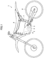
- Figure 1 shows a side view of an electric vehicle 1 according to an embodiment of the present invention.
- Figure 2 shows a perspective view of a frame 2 of the electric vehicle 1.
- the electric vehicle 1 is, for example, a straddled electric vehicle.
- an electric motorcycle is described as an example of the straddled electric vehicle.
- the electric vehicle 1 according to the present invention is not limited thereto, and may be also applied to other vehicles, for example, a four-wheeled electric vehicle.
- the electric vehicle 1 includes an electric motor 3 and an electric circuit 4 mounted to the frame 2, and is the electric motorcycle that decelerates a rotational output of the electric motor 3 by a reduction gear 5 to transmit rotational output to a rear wheel 6.
- the electric circuit 4 includes an electronic control unit (ECU), an inverter, and the like.
- a battery 7 As a power source of the electric motor 3, a battery 7 according to the embodiment of the present invention is mounted to the electric vehicle 1.
- the battery 7 is accommodated in a box-like battery accommodating portion 9 constructed by the frame 2, and is arranged below a saddle 8.
- the battery 7 is charged after being dismounted from the electric vehicle 1. Accordingly, and advantageously, the battery 7 is easily mountable to and dismountable from the electric vehicle 1, that is, mountable to and dismountable from the electric vehicle 1, preferably without using any tool.
- the battery accommodating portion 9 is formed into a box-like shape having an upward opening.
- the saddle 8 is dismounted from the electric vehicle 1, and a cover 10 is opened, thereby allowing access to the battery accommodating portion 9 from an outside.
- the cover 10 can be opened by a simple method using no tool, for example, a method of releasing a latch 11 arranged at an end portion of the cover 10.
- a plurality of (two in the illustrated example) batteries 7 are accommodated in the battery accommodating portion 9.
- Each battery 7 is designed to have a size and a weight suitable for carrying by hand, that is, designed to have, for example, a weight of 10 kg or less.
- the plurality of batteries 7 designed in this manner are mounted, thereby being capable of achieving easy carrying of the batteries 7 manually or by hand, and of ensuring a travelling distance and an output necessary for running of the electric vehicle 1.
- a handle 12 is arranged on an upper portion of each battery 7.
- the handle 12 is held by hand, and then the battery 7 is pulled up. In this manner, the battery 7 can be dismounted from the electric vehicle 1 very easily. Similarly, the battery 7 can be mounted to the electric vehicle 1 very easily.
- the “battery” refers to a component obtained by accommodating a secondary battery module, which includes, as needed, a plurality of battery cells each serving as a member configured to store electric power therein, in a battery case so that the secondary battery module can be handled independently, easily, and safely.
- a lithium-ion battery is suitable as the secondary battery module.
- a control circuit called a battery management system (BMS) configured to perform control of charge and discharge, hold or grasp an amount of remaining charge, regenerative control, and the like is accommodated in the battery case together with the secondary battery module.
- BMS battery management system
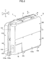
- FIG 3 shows a perspective view of the battery 7 according to this embodiment.
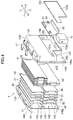
- Figure 4 shows an exploded perspective view of the battery 7. In Figure 4 , illustrations of lead wires are omitted.
- Figure 5 is a perspective view of the battery 7 in a state in which a cover 13C and a connector 16 are removed.
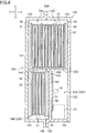
- Figure 6 shows a sectional view of the battery 7 taken along the line VI-VI of Figure 3 .
- Figure 7 shows a view for schematically illustrating electric connection of battery cells 21.
- the X1-X2 direction, the Y1-Y2 direction, and the Z1-Z2 direction illustrated in the drawings respectively indicate three directions parallel to sides of a battery case 13 having a rectangular parallelepiped shape.
- X1 and X2 represent a front side and a rear side, respectively
- Y1 and Y2 represent an upper side and a lower side, respectively
- Z1 and Z2 represent a right side and a left side, respectively.
- the X1-X2 direction, the Y1-Y2 direction, and the Z1-Z2 direction correspond to a fore-and-aft (lengthwise) direction, an up-and-down (heightwise) direction, and a lateral (widthwise) direction of the electric vehicle 1, respectively.
- the battery 7 is mounted in a slightly inclined posture to the electric vehicle 1 so that a front side of the battery 7 is positioned upward of a rear side thereof (see Figure 1 ).
- the X1-X2 direction and the Y1-Y2 direction are slightly inclined with respect to the fore-and-aft direction and the up-and-down direction of the electric vehicle 1, respectively.
- the battery 7 includes a battery case 13 having a rectangular parallelepiped shape and being thinnest in the lateral direction.
- the battery case 13 accommodates a plurality of laminated plate-like battery cells 21 each having a rectangular parallelepiped shape, and a circuit board 51 including the BMS mounted thereon and electrically connected to the battery cells 21. Further, a connector 16 configured to electrically connect the battery 7 to the electric vehicle 1 is mounted to the battery case 13.
- a material of the battery case 13 has impact resistance and also has an insulation property.
- a synthetic resin such as an acrylonitrile-butadiene-styrene (ABS) resin is suitable, for example.
- the battery case 13 includes a first cell accommodating portion 20A having a rectangular parallelepiped shape and being configured to accommodate a first number of battery cells 21 therein, a second cell accommodating portion 20B having a rectangular parallelepiped shape and being configured to accommodate a second number of battery cells 21 therein, and a board accommodating portion 20C configured to accommodate the circuit board 51 therein.
- the second number is smaller than the first number.
- the first number and the second number are not particularly limited. However, it is preferred that, for example, the second number be less than half the first number, and that both the first number and the second number be even numbers. This reason is described later. In this illustrated example, the first number is ten and the second number is four.
- the first cell accommodating portion 20A occupies an upper half of the battery case 13.
- the second cell accommodating portion 20B is adjacent to the first cell accommodating portion 20A in the up-and-down direction.
- the second cell accommodating portion 20B is smaller than the first cell accommodating portion 20A in length in the lateral direction, and occupies a right half of a lower half of the battery case 13.
- the board accommodating portion 20C is adjacent to the first cell accommodating portion 20A in the up-and-down direction, and is also adjacent to the second cell accommodating portion 20B in the lateral direction.
- the board accommodating portion 20C occupies a left half of the lower half of the battery case 13. More specifically, the second cell accommodating portion 20B is slightly larger than the board accommodating portion 20C in length in the lateral direction, and occupies a range slightly larger than a lateral half of the lower half of the battery case 13.
- a partition wall (first partition wall) 155 is arranged between the first cell accommodating portion 20A and the board accommodating portion 20C, and a partition wall (second partition wall) 156 is arranged between the second cell accommodating portion 20B and the board accommodating portion 20C. With this structure, the board accommodating portion 20C is separated from the first cell accommodating portion 20A and the second cell accommodating portion 20B.
- the battery case 13 includes a pair of a right half case body 13A and a left half case body 13B dividable in the lateral direction.
- the right half case body 13A and the left half case body 13B are dividable along a plane perpendicular to the lateral direction.
- the right half case body 13A and the left half case body 13B define the first cell accommodating portion 20A and the second cell accommodating portion 20B when combined together in the lateral direction.
- the right half case body 13A constructs the right half of the battery case 13, and is formed into a box-like shape having a leftward opening.
- a first recessed portion 14A is formed in an upper half of the right half case body 13A, and a second recessed portion 14B is formed in a lower half thereof.
- the left half case body 13B constructs the left half of the battery case 13.
- a box-like first recessed portion 15A having a rightward opening is formed in an upper half of the left half case body 13B, and a box-like second recessed portion 15B having a leftward opening is formed in a lower half thereof. That is, the first recessed portion 15A is open to an inside of the battery case 13, whereas the second recessed portion 15B is open to an outside of the battery case 13.
- the first recessed portion 14A of the right half case body 13A and the first recessed portion 15A of the left half case body 13B are combined together, to thereby define the first cell accommodating portion 20A.
- the second recessed portion 14B of the right half case body 13A defines the second cell accommodating portion 20B.
- the second recessed portion 15B of the left half case body 13B which is open to the outside of the battery case, defines the board accommodating portion 20C.
- the battery case 13 further includes the cover 13C configured to close the opening of the second recessed portion 15B. Without dividing the right half case body 13A and the left half case body 13B from each other, a user only dismounts the cover 13C from the battery case 13, thereby being capable of obtaining access to the circuit board 51 without touching the battery cells 21.
- the right half case body 13A includes a rectangular main wall 141 occupying an entire right side portion of the battery case 13, a peripheral wall 143 extending leftward from a peripheral edge of the main wall 141, and a partition wall 145 extending leftward from a center of the main wall 141 in the up-and-down direction.
- the peripheral wall 143 includes an upper portion, a lower portion, a front portion, and a rear portion.
- the partition wall 145 extends in the fore-and-aft direction at the center of the main wall 141 in the up-and-down direction, and partitions an inner space of the right half case body 13A.
- a space above the partition wall 145 corresponds to the first recessed portion 14A
- a space below the partition wall 145 corresponds to the second recessed portion 14B. That is, the first recessed portion 14A is defined by an upper half of the main wall 141, an upper half of the peripheral wall 143, and the partition wall 145, whereas the second recessed portion 14B is defined by a lower half of the main wall 141, a lower half of the peripheral wall 143, and the partition wall 145.
- first recessed portion 14A and the second recessed portion 14B share the partition wall 145.
- Each of the first recessed portion 14A and the second recessed portion 14B is formed to have a size capable of accommodating the battery cells 21 arranged so that a longitudinal direction of each of the battery cells is along the fore-and-aft direction and a width direction thereof is along the up-and-down direction.
- the partition wall 145 is not connected to the front portion of the peripheral wall 143, and a front end of the partition wall 145 is separated from the peripheral wall 143. Accordingly, the first recessed portion 14A and the second recessed portion 14B are not completely separated from each other.
- a protruding wall 146 extending in the up-and-down direction is formed at the front end of the partition wall 145 (see Figure 4 ). Although not shown, a rear end of the partition wall 145 is constructed in the same manner. A gap between the front portion of the peripheral wall 143 and the protruding wall 146 is used to arrange lead wires described later.
- a flange 149 extending outward along a plane perpendicular to the lateral direction is formed at an edge of a left end of the peripheral wall 143.
- the flange 149 includes a plurality of fastening portions 149a that are formed for fastening with screws or the like so as to be separated from each other.
- a rib 148 extending in the lateral direction and having the same height as that of the flange 149 is formed on an outer surface of the lower portion of the peripheral wall 143.
- the left half case body 13B includes a rectangular main wall 151 occupying an upper half of a left side portion of the battery case 13, and a rectangular partition wall 156 positioned below and rightward of the main wall 151 so as to be parallel to the main wall 151.
- the left half case body 13B includes a peripheral wall 153 extending in the lateral direction and being connected to peripheral edges of the main wall 151 and the partition wall 156 so as to surround the main wall 151 and the partition wall 156, and a partition wall 155 extending in the lateral direction and being connected to a lower edge of the main wall 151 and an upper edge of the partition wall 156.
- the partition wall 156 is arranged at a position close to an edge of a right end of the left half case body 13B, specifically, a position slightly leftward of the edge of the right end of the left half case body 13B.
- the peripheral wall 153 extends leftward from the peripheral edge of the main wall 151 excluding the lower edge thereof. Further, the peripheral wall 153 extends leftward from the peripheral edge of the partition wall 156 excluding the upper edge thereof, and also slightly extends rightward.
- a retreat portion 157 is formed at a front lower portion of the peripheral wall 153, and is bent into an L-shape so as to be convex inward.
- the partition wall 155 extends in the fore-and-aft direction at the center of the left half case body 13B in the up-and-down direction, and is connected to the lower edge of the main wall 151, the upper edge of the partition wall 156, and a front portion and a rear portion of the peripheral wall 153.
- a space above the partition wall 155 corresponds to the first recessed portion 15A
- a space below the partition wall 155 corresponds to the second recessed portion 15B. That is, the first recessed portion 15A is defined by the main wall 151, an upper half of the peripheral wall 153, and the partition wall 155, whereas the second recessed portion 15B is defined by the partition wall 156, a lower half of the peripheral wall 153, and the partition wall 155. In this case, the first recessed portion 15A and the second recessed portion 15B share the partition wall 155. Further, the partition wall 156 constructs a bottom portion of the second recessed portion 15B.
- the left half case body 13B exhibits an S-shaped cross-section when taken along a plane perpendicular to the fore-and-aft direction. That is, the upper portion of the peripheral wall 153, the main wall 151, the partition wall 155, the partition wall 156, and the lower portion of the peripheral wall 153 define the S-shaped cross-section.
- the first recessed portion 15A is formed to have a size capable of accommodating the battery cells 21 arranged so that the longitudinal direction of each of the battery cells is along the fore-and-aft direction and that the width direction thereof is along the up-and-down direction.
- the second recessed portion 15B is formed to have a size capable of accommodating the circuit board 51 arranged so that a longitudinal direction of the circuit board 51 is along the fore-and-aft direction and that a width direction thereof is along the up-and-down direction.
- a right edge of the partition wall 155 and the upper edge of the partition wall 156 are connected to each other at a connection portion 150.
- the partition wall 155 and the partition wall 156 are, for example, formed integrally with each other at the connection portion 150.
- an angle formed between the partition wall 155 and the partition wall 156 is, for example, 90 degrees.
- a protruding wall 154 is formed to extend rightward from the connection portion 150.
- the protruding wall 154 is extended rightward from the partition wall 155, and is formed so as to protrude rightward from the partition wall 156.
- the retreat portion 157 is formed at the front lower portion of the peripheral wall 153 so as to cut out a front lower portion of the second recessed portion 15B.
- On an outer side of the retreat portion 157 there is formed a third recessed portion 15C that is defined by the retreat portion 157 and the partition wall 156 and is open to front, lower, and left sides of the battery case 13. That is, the retreat portion 157 divides the second recessed portion 15B and the third recessed portion 15C.
- the connector 16 is arranged in the third recessed portion 15C.
- two through-holes 157a passing through the retreat portion 157 in the up-and-down direction are formed at positions separated from each other in the fore-and-aft direction.
- An end portion 63e of a lead wire 63 and an end portion 73e of a lead wire 73 are to be inserted into the two through-holes 157a, respectively.
- a through-hole 156a passing through the partition wall 156 in the lateral direction is formed in a front upper portion of the partition wall 156, that is, above the retreat portion 157.
- Lead wires 61 and 71 are to be inserted into the through-hole 156a.
- the through-hole 156a is indicated by the broken line in Figure 5 .
- a plurality of bosses 153a for fastening the cover 13C with screws or the like are formed to be separated from each other. Positions of the bosses 153a correspond to positions of screw holes 133a formed in the peripheral edge of the cover 13C.
- the bosses 153a are formed so as to swell or protrude from the peripheral wall 153 and the partition wall 155 toward an inside of the second recessed portion 15B.
- a flange 159 extending outward along a plane perpendicular to the lateral direction is formed at an edge of a right end of the left half case body 13B.
- the flange 159 includes a plurality of fastening portions 159a formed for fastening with screws or the like.
- a rib 158 extending in the lateral direction and having the same height as that of the flange 159 is formed on an outer surface of the lower portion of the peripheral wall 153.
- the flange 149 formed on the right half case body 13A and the flange 159 formed on the left half case body 13B are joined together, and the fastening portions 149a and 159a are fastened together with screws or the like, thereby hermetically sealing the battery case 13.
- a liquid gasket is applied or provided between the flange 149 and the flange 159.
- the right half case body 13A and the left half case body 13B are combined together, thereby defining the first cell accommodating portion 20A and the second cell accommodating portion 20B.
- the first cell accommodating portion 20A is defined by a combination of the first recessed portion 14A of the right half case body 13A and the first recessed portion 15A of the left half case body 13B. That is, the first cell accommodating portion 20A is defined by the upper half of the main wall 141, the upper half of the peripheral wall 143, and the partition wall 145 of the right half case body 13A, and by the main wall 151, the upper half of the peripheral wall 153, the partition wall 155, and the protruding wall 154 of the left half case body 13B.
- the second cell accommodating portion 20B is defined in such a manner that the opening of the second recessed portion 14B of the right half case body 13A is closed by the partition wall 156 of the left half case body 13B. More specifically, the second cell accommodating portion 20B is defined by the lower half of the main wall 141, the lower half of the peripheral wall 143, and the partition wall 145 of the right half case body 13A, and by the partition wall 156, the protruding wall 154 of the left half case body 13B, and a portion of the peripheral wall 153 extending rightward of the partition wall 156.
- the partition wall 145 of the right half case body 13A and the protruding wall 154 of the left half case body 13B are also joined together.
- the partition wall 145 and the protruding wall 154 are formed to prevent misalignment of the battery cells 21 accommodated in the cell accommodating portions 20A and 20B, but the partition wall 145 and the protruding wall 154 may be omitted.
- the board accommodating portion 20C is defined in such a manner that the opening of the second recessed portion 15B, which is open to an outside of the left half case body 13B, is closed by the cover 13C. More specifically, the board accommodating portion 20C is defined by the partition wall 156, the lower half of the peripheral wall 153, and the partition wall 155 of the left half case body 13B, and by the cover 13C.
- the cover 13C is formed into a shape having a cut-out front lower portion so as to avoid the third recessed portion 15C.
- the screw holes 133a formed in the peripheral edge of the cover 13C, and the bosses 153a formed on the peripheral edge of the second recessed portion 15B are fastened together with screws or the like, thereby fixing the cover 13C to the left half case body 13B.
- the connector 16 having a rectangular parallelepiped shape is fitted into the third recessed portion 15C positioned in the front lower portion of the left half case body 13B and formed on the outer side of the retreat portion 157 of the peripheral wall 153.
- the connector 16 is, for example, a female connector (so-called receptacle), and includes a lower surface having an insertion hole (not shown) formed therein.
- a male connector (so-called plug) arranged in the electric vehicle 1 (to extend upward) is inserted into the insertion hole.
- the male connector is arranged inside the battery accommodating portion 9 of the electric vehicle 1 to extend upward from a bottom surface thereof.
- the male connector arranged on the bottom surface of the battery accommodating portion 9 is inserted into the connector 16 arranged on the front lower portion of the battery case 13.
- the plurality of battery cells 21 accommodated in the battery case 13 are parted into the two cell accommodating portions 20A and 20B, and the cell accommodating portions 20A and 20B are aligned in the up-and-down direction. In this manner, reduction of a lateral thickness of the battery case 13 is beneficially achieved.
- the number of battery cells 21 accommodated in the second cell accommodating portion 20B is set to be smaller than the number of battery cells 21 accommodated in the first cell accommodating portion 20A.
- a lateral thickness of the second cell accommodating portion 20B is smaller than a lateral thickness of the first cell accommodating portion 20A.
- a space defined in this structure that is, a space adjacent to the second cell accommodating portion 20B in the lateral direction and also adjacent to the first cell accommodating portion 20A in the up-and-down direction is used as the board accommodating portion 20C, thereby achieving the reduction of the lateral thickness of the battery case 13. It will be appreciated that this advantageous arrangement can be used in other embodiments of the present invention.
- the partition wall 155 is arranged between the first cell accommodating portion 20A and the board accommodating portion 20C
- the partition wall 156 is arranged between the second cell accommodating portion 20B and the board accommodating portion 20C.
- the board accommodating portion 20C is beneficially separated from the cell accommodating portions 20A and 20B.
- the partition wall 155 and the partition wall 156 are formed integrally with each other at the connection portion 150, thereby being capable of effectively preventing or mitigating the leaking electrolyte from entering the board accommodating portion 20C.
- the angle formed at the connection portion 150 between the partition wall 155 and the partition wall 156 is set to 90 degrees, thereby being capable of achieving downsizing of the cell accommodating portions 20A and 20B and the board accommodating portion 20C.
- the connector 16 is arranged in the lower portion of the battery case 13. Accordingly, the first cell accommodating portion 20A is arranged in the upper half of the battery case 13, and the second cell accommodating portion 20B and the board accommodating portion 20C are arranged in the lower half of the battery case 13.
- the present invention is not limited to this mode.
- the first cell accommodating portion 20A may be arranged in the lower half of the battery case 13, and the second cell accommodating portion 20B and the board accommodating portion 20C may be arranged in the upper half of the battery case 13.
- the first cell accommodating portion 20A may be arranged in a front half of the battery case 13, and the second cell accommodating portion 20B and the board accommodating portion 20C may be arranged in a rear half of the battery case 13.
- an inverse arrangement may be adopted.
- positions of the second cell accommodating portion 20B and the board accommodating portion 20C may be switched relative to each other in the lateral direction.
- the first number of (ten in the illustrated example) battery cells 21 are accommodated in the first cell accommodating portion 20A of the battery case 13, and the second number of (four in the illustrated example) battery cells 21 are accommodated in the second cell accommodating portion 20B.
- the second number is smaller than the first number.
- the battery cells 21 are accommodated in the cell accommodating portions 20A and 20B under such a state that the longitudinal direction of each of the battery cells is along the fore-and-aft direction, that the width direction thereof is along the up-and-down direction, and that the battery cells are stacked on each other in the lateral direction.
- a terminal 23 protruding forward and a terminal 23 protruding rearward are arranged on a front end and a rear end of each of the battery cells 21, respectively.
- a plurality of metal plates 30 and a pair of cushion members 41 are accommodated in a state of being stacked in the lateral direction.
- the pair of cushion members 41 are arranged on outermost lateral sides, respectively.
- the pair of cushion members 41 are interposed between the battery cells 21 and the battery case 13 in the lateral direction, and are held in contact with the battery case 13.
- the metal plates 30 are arranged in several gaps defined between the stacked battery cells 21, and in a gap defined between one battery cell 21 and one of the cushion members 41.
- a plurality of metal plates 30 and a pair of cushion members 42 are accommodated in a state of being stacked in the lateral direction.
- the pair of cushion members 42 are arranged on outermost lateral sides, respectively.
- the pair of cushion members 42 are interposed between the battery cells 21 and the battery case 13 in the lateral direction, and are held in contact with the battery case 13.
- the metal plates 30 are arranged in several gaps defined between the stacked battery cells 21, and in a gap defined between one battery cell 21 and one of the cushion members 42.
- the metal plates 30 are rectangular plates made of a metal material such as aluminum. Concave cutouts for avoiding the terminals 23 are formed in a front end and a rear end of each of the metal plates 30, respectively.
- the metal plates 30 are brought into abutment against inside members of the battery case 13 (such as the peripheral walls 143 and 153, the partition walls 145 and 155, and the protruding wall 146), thereby being capable of preventing damage of the battery cells 21.
- Each of the cushion members 41 and 42 is made of, for example, a sponge or foam like material, and is formed into a rectangular parallelepiped shape being thinnest in the lateral direction.
- Each of the cushion members 41 and 42 is interposed between the battery case 13 and the battery cells 21, thereby softening an impact transmitted from the battery case 13 to the battery cells 21.
- Each of the cushion members 41 and 42 is interposed between the battery case 13 and the battery cells 21 in a state of being compressed in the lateral direction.
- the battery cells 21, the metal plates 30, and the cushion members 41 and 42 accommodated in the cell accommodating portions 20A and 20B are stacked on each other in the lateral direction corresponding to a direction of dividing the battery case 13, and are sandwiched between the right half case body 13A and the left half case body 13B.
- the battery cells 21, the metal plates 30, and the cushion members 41 and 42 can be accommodated easily, and positional stabilization can be achieved.
- the left half case body 13B is brought close to the right half case body 13A, and then the right half case body 13A and the left half case body 13B are combined together while the cushion members 41 and 42 are compressed in the stacking direction.
- the battery cells 21, the metal plates 30, and the cushion members 41 and 42 are fastened in the stacking direction. Accordingly, in the midst of accommodation and even afterward, it is possible to prevent misalignment in the planar direction perpendicular to the stacking direction.
- a direction of stacking the battery cells 21 accommodated in the first cell accommodating portion 20A may be different from a direction of stacking the battery cells 21 accommodated in the second cell accommodating portion 20B.
- the battery cells are stacked on each other in the up-and-down direction in the first cell accommodating portion 20A, whereas the battery cells are stacked on each other in the lateral direction in the second cell accommodating portion 20B.
- a direction, along which the second cell accommodating portion 20B and the board accommodating portion 20C are adjacent to each other be the same as the direction of stacking the battery cells 21 accommodated in the second cell accommodating portion 20B.
- the cushion members 42 arranged in the second cell accommodating portion 20B are thicker than the cushion members 41 arranged in the first cell accommodating portion 20A. This is because an entire heat generating amount is lower in the second cell accommodating portion 20B in which the smaller number of battery cells 21 are accommodated, with the result that the second cell accommodating portion 20B is more easily cooled. That is, the cushion members 42 are thicker than the cushion members 41, thereby enhancing thermal insulation in the second cell accommodating portion 20B. Thus, a temperature in the first cell accommodating portion 20A and a temperature in the second cell accommodating portion 20B are equalized.
- the number of battery cells 21 accommodated in the second cell accommodating portion 20B is beneficially equal to or smaller than a half of the number of battery cells 21 accommodated in the first cell accommodating portion 20A, but the cushion members 42 are thicker than the cushion members 41. Accordingly, a lateral length of the second cell accommodating portion 20B is larger than a half of a lateral length of the first cell accommodating portion 20A. That is, when considering thickening the cushion members 42 in the second cell accommodating portion 20B in addition to securing a space as the board accommodating portion 20C, it is preferred that the number of battery cells 21 accommodated in the second cell accommodating portion 20B be equal to or smaller than the half of the number of battery cells 21 accommodated in the first cell accommodating portion 20A.
- the rectangular circuit board 51 is arranged in the board accommodating portion 20C in parallel to a surface of the board accommodating portion 20C, which extends perpendicularly to the lateral direction.
- the circuit board 51 is fixed, with a screw or the like, to the partition wall 156 being the bottom portion of the second recessed portion 15B formed in the left half case body 13B of the battery case 13 so as to be open outward.
- the circuit board 51 is arranged in this manner, thereby being capable of achieving reduction of a lateral thickness of the board accommodating portion 20C, and also the reduction of the lateral thickness of the battery case 13.
- Two connectors 55 configured to connect the lead wires 61,63 to the circuit board 51 are arranged on a surface of the circuit board 51 to be separated from each other in the fore-and-aft direction.
- a heat sink 53 having a rectangular parallelepiped shape and being mounted at a lower edge of the circuit board 51, and a fuse 57 configured to protect the circuit board 51 are accommodated in the board accommodating portion 20C.
- the fuse 57 is connected to the lead wires 71 and 73.
- the lead wires 61 and 71 are led from the cell accommodating portions 20A and 20B into the board accommodating portion 20C through through-hole 156a formed in the front upper portion of the partition wall 156.
- the through-hole 156a through which the lead wires 61 and 71 are led is beneficially sealed, e.g. by a curable resin material. With this structure, even when the electrolyte leaks from the battery cells 21 in the cell accommodating portions 20A and 20B, the leaking electrolyte can be prevented from entering the board accommodating portion 20C.
- the through-hole 156a may be formed in the partition wall 155.
- the lead wires 63 and 73 are led from the board accommodating portion 20C into the third recessed portion 15C through the through-holes 157a formed in the upper portion of the retreat portion 157, and the end portion 63e of the lead wire 63 and the end portion 73e of the lead wire 73 protruding from the through-holes 157a toward the third recessed portion 15C are connected to the connector 16.
- the plurality of battery cells 21 accommodated in the cell accommodating portions 20A and 20B are connected to each other in series.
- the battery cells 21 are stacked on each other so that the positive terminals 23 alternate with the negative terminals 23, and a pair of the positive terminal 23 and the negative terminal 23 adjacent to each other are connected to each other by a connection member 29. This facilitates series connection of the battery cells 21.
- the lead wire 61 to be led into the board accommodating portion 20C is connected to the negative terminal 23 of one of the battery cells 21 accommodated in the first cell accommodating portion 20A.
- the one of the battery cells 21 is positioned on one end side in the stacking direction.
- the lead wire 62, which is to be connected to the battery cells 21 accommodated in the second cell accommodating portion 20B, is connected to the positive terminal 23 of another one of the battery cells 21 positioned on the other end side in the stacking direction.
- the lead wire 72 which is to be connected to the battery cells 21 accommodated in the first cell accommodating portion 20A, is connected to the negative terminal 23 of one of the battery cells 21 accommodated in the second cell accommodating portion 20B.
- the one of the battery cells 21 is positioned on one end side in the stacking direction.
- the lead wire 71 to be led into the board accommodating portion 20C is connected to the positive terminal 23 of another one of the battery cells 21 positioned on the other end side in the stacking direction.
- the lead wires 62 and 72 are connected to each other by the connection member 59.
- the lead wires 62 and 72 can be connected to each other in the cell accommodating portion 20A or 20B, or can be led into the board accommodating portion 20C and connected to each other in the board accommodating portion 20C.
- the sum of the number of battery cells 21 accommodated in the first cell accommodating portion 20A and the number of battery cells 21 accommodated in the second cell accommodating portion 20B is an even number.
- both of the lead wires 61 and 71 can be arranged on the front side of the battery case to be led into the board accommodating portion 20C through the through-hole 156a.
- both of the number of battery cells 21 accommodated in the first cell accommodating portion 20A and the number of battery cells 21 accommodated in the second cell accommodating portion 20B are even numbers.
- all of the four lead wires 61, 62, 71, and 72 can be arranged on the front side of the battery case to be led into the board accommodating portion 20C through the through-hole 156a.
- straddle-type vehicle or motor vehicle used herein, and as used in the art, is meant to include at least the following terms also used in the art:
Landscapes
- Engineering & Computer Science (AREA)
- Chemical & Material Sciences (AREA)
- General Chemical & Material Sciences (AREA)
- Electrochemistry (AREA)
- Chemical Kinetics & Catalysis (AREA)
- Power Engineering (AREA)
- Mechanical Engineering (AREA)
- Transportation (AREA)
- Manufacturing & Machinery (AREA)
- Life Sciences & Earth Sciences (AREA)
- Sustainable Energy (AREA)
- Sustainable Development (AREA)
- Microelectronics & Electronic Packaging (AREA)
- Materials Engineering (AREA)
- Battery Mounting, Suspending (AREA)
- Sealing Battery Cases Or Jackets (AREA)
- Secondary Cells (AREA)
Abstract
Description
- The present invention relates to a battery, a battery case, and an electric vehicle, e.g. a straddled vehicle.
- In Japanese Patent Application Laid-open No.
2007-087909 - Thinning of a battery to be mounted to an electric vehicle or the like may be required. For example, in a straddled electric vehicle, in general, the battery is arranged below a seat. Accordingly, it is preferred that the battery be thinned in a vehicle width direction so as to enable a rider to easily straddle the vehicle.
- Further, in a battery to be mounted to the electric vehicle or the like, in addition to battery cells, a circuit board configured to control charging and to hold an amount of remaining charge is sometimes provided. It is desirable to adopt a configuration capable of preventing the circuit board from being soaked in a leaking electrolyte even if or when electrolyte leaks from the battery cells.
- At least one embodiment of at least one aspect of the present invention has an object of providing a battery, a battery case, and/or an electric vehicle capable of achieving thinning of the battery, and/or of separating a circuit board from battery cells.
- It is an object of at least one embodiment of at least one aspect of the present invention to obviate or at least mitigate one or more problems or disadvantages in the prior art.
- Various aspects of the present invention are defined in the appended independent claims. Some preferred features are defined in the appended dependent claims.
- According to one aspect of the present invention there is provided a battery, such as an electric battery.
- The battery may comprise a plurality of battery cells. The battery may comprise a circuit board, which may be electrically connected to the plurality of battery cells. The battery may comprise a battery case, which may comprise a rectangular parallelepiped shape. The battery case may be configured to accommodate the plurality of battery cells and the circuit board therein. The battery case may comprise or include a first cell accommodating portion, which may have a rectangular parallelepiped shape. The first cell accommodating portion may be configured to accommodate a first number of the plurality of battery cells therein. The battery case may comprise or include a second cell accommodating portion, which may have a rectangular parallelepiped shape. The second cell accommodating portion may be configured to accommodate a second number of the plurality of battery cells therein. The battery case may comprise a board accommodating portion, which may be configured to accommodate the circuit board therein. The second number may be smaller than the first number. The second cell accommodating portion may be shorter than the first cell accommodating portion, e.g. in one of three directions parallel to sides of the battery case. The board accommodating portion may be adjacent to the second cell accommodating portion in the one of the three directions. The battery case may comprise or include a first partition wall, which may be arranged between the first cell accommodating portion and the board accommodating portion. The battery case may comprise or include a second partition wall, which may be arranged between the second cell accommodating portion and the board accommodating portion.
- The number of battery cells accommodated in the second cell accommodating portion may be set to be smaller than the number of battery cells accommodated in the first cell accommodating portion. The second cell accommodating portion may be shorter than the first cell accommodating portion in length, e.g. in the one of the three directions, and a space (defined in this structure) may be used as the board accommodating portion, thereby preferably being capable of reducing an entire thickness of the battery including the cell accommodating portions and the board accommodating portion. The partition wall may be arranged between the board accommodating portion and each of the cell accommodating portions. Thus, even when an electrolyte leaks from the battery cells, the circuit board preferably may be prevented or at least mitigated from being soaked in the leaking electrolyte.
- The first partition wall may comprise a first edge positioned on the second partition wall side.
- The second partition wall may comprise a second edge positioned on the first partition wall side.
- The first edge and the second edge may be connected to each other at a connection portion.
- The first partition wall and the second partition wall may be formed integrally with each other at the connection portion.
- An angle formed at the connection portion between the first partition wall and the second partition wall may be substantially 90 degrees.
- The second number of the plurality of battery cells may be stacked on each other in the one of the three directions.
- The first number of the plurality of battery cells may be stacked on each other in the one of the three directions.
- The circuit board may be arranged in parallel to a surface which extends perpendicularly to the one of the three directions.
- The battery case may comprise a pair of half case bodies, which may be dividable in the one of the three directions, and may be configured to define the first cell accommodating portion and the second cell accommodating portion when the pair of half case bodies are combined together,
- One of the pair of half case bodies may comprise an inward opening recessed portion, which may be formed to be open to an inside of the battery case, and may be configured to define a part of the first cell accommodating portion.
- One of the pair of half case bodies may comprise an outward opening recessed portion, which may be formed to be open to an outside of the battery case, and may be configured to define at least a part of the board accommodating portion.
- The inward opening recessed portion and the outward opening recessed portion may share the first partition wall.
- The second partition wall may define a bottom portion of the outward opening recessed portion.
- The battery case may comprise a cover configured to cover the outward opening recessed portion.
- The battery may comprise cushion members arranged between the battery case and the plurality of battery cells.
- At least one of the cushion members arranged in the second cell accommodating portion may be thicker than at least one of the cushion members arranged in the first cell accommodating portion.
- One of the first partition wall and the second partition wall may comprise a through-hole formed therein, through which a lead wire connecting the plurality of battery cells and the circuit board to each other may be led or fed, and the through-hole through which the lead wire may be led is sealed.
- The battery may comprise a connector, which may be adjacent to the second cell accommodating portion in the one of the three directions, and may be electrically connected to the circuit board.
- According to a second aspect of the present invention there is provided a battery case.
- The battery case may comprise a rectangular parallelepiped shape.
- The battery case may be configured to accommodate a plurality of battery cells and a circuit board electrically connected to the plurality of battery cells.
- The battery case may comprise a first cell accommodating portion, which may have a rectangular parallelepiped shape.
- The first cell accommodating portion may be configured to accommodate a first number of the plurality of battery cells therein.
- The battery case may comprise a second cell accommodating portion, which may have a rectangular parallelepiped shape.
- The second cell accommodating portion may be configured to accommodate a second number of the plurality of battery cells therein.
- The second number may be smaller than the first number. The second cell accommodating portion may be shorter than the first cell accommodating portion, e.g. in one of the three directions parallel to sides of the battery case.
- The battery case may comprise a board accommodating portion, which may be adjacent to the second cell accommodating portion in the one of the three directions, and may be configured to accommodate the circuit board therein.
- The battery case may comprise a first partition wall, which may be arranged between the first cell accommodating portion and the board accommodating portion.
- The battery case may comprise a second partition wall, which may be arranged between the second cell accommodating portion and the board accommodating portion.
- According to a third aspect of the present invention there is provided an electric vehicle comprising at least one battery according to the first aspect of the present invention.
- It will be appreciated that features analogous to those described in relation to any of the above aspects may be individually and separably or in combination applicable to any of the other aspects.
- An embodiment of the present invention will now be described, by way of example only, with reference to the accompanying drawings, which are:
- Figure 1
- a side view of an electric vehicle according to an embodiment of the present invention;
- Figure 2
- a perspective view of a frame of the electric vehicle of
Figure 1 ; - Figure 3
- a perspective view of a battery according to the embodiment of the present invention;
- Figure 4
- an exploded perspective view of the battery of
Figure 3 ; - Figure 5
- a perspective view of the battery of
Figure 3 in a state in which a cover is removed; - Figure 6
- a sectional view of the battery of
Figure 3 ; - Figure 7
- a view schematically illustrating electric connection of battery cells of the battery of
Figure 3 ; and - Figure 8
- a view schematically illustrating a modification of arrangement of the battery cells of the battery of
Figure 3 . - An embodiment of the present invention will now be described with reference to the accompanying drawings.
-
Figure 1 shows a side view of an electric vehicle 1 according to an embodiment of the present invention.Figure 2 shows a perspective view of aframe 2 of the electric vehicle 1. The electric vehicle 1 is, for example, a straddled electric vehicle. Herein, an electric motorcycle is described as an example of the straddled electric vehicle. However, it will be appreciated that the electric vehicle 1 according to the present invention is not limited thereto, and may be also applied to other vehicles, for example, a four-wheeled electric vehicle. - In this embodiment, the electric vehicle 1 includes an
electric motor 3 and anelectric circuit 4 mounted to theframe 2, and is the electric motorcycle that decelerates a rotational output of theelectric motor 3 by a reduction gear 5 to transmit rotational output to arear wheel 6. Theelectric circuit 4 includes an electronic control unit (ECU), an inverter, and the like. - As a power source of the
electric motor 3, abattery 7 according to the embodiment of the present invention is mounted to the electric vehicle 1. Thebattery 7 is accommodated in a box-likebattery accommodating portion 9 constructed by theframe 2, and is arranged below asaddle 8. In this embodiment, thebattery 7 is charged after being dismounted from the electric vehicle 1. Accordingly, and advantageously, thebattery 7 is easily mountable to and dismountable from the electric vehicle 1, that is, mountable to and dismountable from the electric vehicle 1, preferably without using any tool. - The
battery accommodating portion 9 is formed into a box-like shape having an upward opening. Thesaddle 8 is dismounted from the electric vehicle 1, and acover 10 is opened, thereby allowing access to thebattery accommodating portion 9 from an outside. Note that, thecover 10 can be opened by a simple method using no tool, for example, a method of releasing alatch 11 arranged at an end portion of thecover 10. - A plurality of (two in the illustrated example)
batteries 7 are accommodated in thebattery accommodating portion 9. Eachbattery 7 is designed to have a size and a weight suitable for carrying by hand, that is, designed to have, for example, a weight of 10 kg or less. The plurality ofbatteries 7 designed in this manner are mounted, thereby being capable of achieving easy carrying of thebatteries 7 manually or by hand, and of ensuring a travelling distance and an output necessary for running of the electric vehicle 1. - A
handle 12 is arranged on an upper portion of eachbattery 7. Thehandle 12 is held by hand, and then thebattery 7 is pulled up. In this manner, thebattery 7 can be dismounted from the electric vehicle 1 very easily. Similarly, thebattery 7 can be mounted to the electric vehicle 1 very easily. - Herein, the "battery" refers to a component obtained by accommodating a secondary battery module, which includes, as needed, a plurality of battery cells each serving as a member configured to store electric power therein, in a battery case so that the secondary battery module can be handled independently, easily, and safely. For example, a lithium-ion battery is suitable as the secondary battery module.
- In addition, in the
battery 7 according to this embodiment, a control circuit called a battery management system (BMS) configured to perform control of charge and discharge, hold or grasp an amount of remaining charge, regenerative control, and the like is accommodated in the battery case together with the secondary battery module. -
Figure 3 shows a perspective view of thebattery 7 according to this embodiment.Figure 4 shows an exploded perspective view of thebattery 7. InFigure 4 , illustrations of lead wires are omitted.Figure 5 is a perspective view of thebattery 7 in a state in which acover 13C and aconnector 16 are removed.Figure 6 shows a sectional view of thebattery 7 taken along the line VI-VI ofFigure 3 .Figure 7 shows a view for schematically illustrating electric connection ofbattery cells 21. - The X1-X2 direction, the Y1-Y2 direction, and the Z1-Z2 direction illustrated in the drawings respectively indicate three directions parallel to sides of a
battery case 13 having a rectangular parallelepiped shape. In the following description, X1 and X2 represent a front side and a rear side, respectively, and Y1 and Y2 represent an upper side and a lower side, respectively. Further, Z1 and Z2 represent a right side and a left side, respectively. - The X1-X2 direction, the Y1-Y2 direction, and the Z1-Z2 direction correspond to a fore-and-aft (lengthwise) direction, an up-and-down (heightwise) direction, and a lateral (widthwise) direction of the electric vehicle 1, respectively. More specifically, the
battery 7 is mounted in a slightly inclined posture to the electric vehicle 1 so that a front side of thebattery 7 is positioned upward of a rear side thereof (seeFigure 1 ). Accordingly, the X1-X2 direction and the Y1-Y2 direction are slightly inclined with respect to the fore-and-aft direction and the up-and-down direction of the electric vehicle 1, respectively. - The
battery 7 includes abattery case 13 having a rectangular parallelepiped shape and being thinnest in the lateral direction. Thebattery case 13 accommodates a plurality of laminated plate-like battery cells 21 each having a rectangular parallelepiped shape, and acircuit board 51 including the BMS mounted thereon and electrically connected to thebattery cells 21. Further, aconnector 16 configured to electrically connect thebattery 7 to the electric vehicle 1 is mounted to thebattery case 13. - It is preferred that a material of the
battery case 13 has impact resistance and also has an insulation property. A synthetic resin such as an acrylonitrile-butadiene-styrene (ABS) resin is suitable, for example. - As illustrated in
Figure 6 , thebattery case 13 includes a firstcell accommodating portion 20A having a rectangular parallelepiped shape and being configured to accommodate a first number ofbattery cells 21 therein, a secondcell accommodating portion 20B having a rectangular parallelepiped shape and being configured to accommodate a second number ofbattery cells 21 therein, and aboard accommodating portion 20C configured to accommodate thecircuit board 51 therein. The second number is smaller than the first number. The first number and the second number are not particularly limited. However, it is preferred that, for example, the second number be less than half the first number, and that both the first number and the second number be even numbers. This reason is described later. In this illustrated example, the first number is ten and the second number is four. - The first
cell accommodating portion 20A occupies an upper half of thebattery case 13. The secondcell accommodating portion 20B is adjacent to the firstcell accommodating portion 20A in the up-and-down direction. The secondcell accommodating portion 20B is smaller than the firstcell accommodating portion 20A in length in the lateral direction, and occupies a right half of a lower half of thebattery case 13. Theboard accommodating portion 20C is adjacent to the firstcell accommodating portion 20A in the up-and-down direction, and is also adjacent to the secondcell accommodating portion 20B in the lateral direction. Theboard accommodating portion 20C occupies a left half of the lower half of thebattery case 13. More specifically, the secondcell accommodating portion 20B is slightly larger than theboard accommodating portion 20C in length in the lateral direction, and occupies a range slightly larger than a lateral half of the lower half of thebattery case 13. - A partition wall (first partition wall) 155 is arranged between the first
cell accommodating portion 20A and theboard accommodating portion 20C, and a partition wall (second partition wall) 156 is arranged between the secondcell accommodating portion 20B and theboard accommodating portion 20C. With this structure, theboard accommodating portion 20C is separated from the firstcell accommodating portion 20A and the secondcell accommodating portion 20B. - The
battery case 13 includes a pair of a righthalf case body 13A and a lefthalf case body 13B dividable in the lateral direction. The righthalf case body 13A and the lefthalf case body 13B are dividable along a plane perpendicular to the lateral direction. The righthalf case body 13A and the lefthalf case body 13B define the firstcell accommodating portion 20A and the secondcell accommodating portion 20B when combined together in the lateral direction. - The right
half case body 13A constructs the right half of thebattery case 13, and is formed into a box-like shape having a leftward opening. A first recessedportion 14A is formed in an upper half of the righthalf case body 13A, and a second recessedportion 14B is formed in a lower half thereof. - The left
half case body 13B constructs the left half of thebattery case 13. A box-like first recessedportion 15A having a rightward opening is formed in an upper half of the lefthalf case body 13B, and a box-like second recessedportion 15B having a leftward opening is formed in a lower half thereof. That is, the first recessedportion 15A is open to an inside of thebattery case 13, whereas the second recessedportion 15B is open to an outside of thebattery case 13. - When the right
half case body 13A and the lefthalf case body 13B are combined together, the first recessedportion 14A of the righthalf case body 13A and the first recessedportion 15A of the lefthalf case body 13B are combined together, to thereby define the firstcell accommodating portion 20A. The second recessedportion 14B of the righthalf case body 13A defines the secondcell accommodating portion 20B. - The second recessed
portion 15B of the lefthalf case body 13B, which is open to the outside of the battery case, defines theboard accommodating portion 20C. Thebattery case 13 further includes thecover 13C configured to close the opening of the second recessedportion 15B. Without dividing the righthalf case body 13A and the lefthalf case body 13B from each other, a user only dismounts thecover 13C from thebattery case 13, thereby being capable of obtaining access to thecircuit board 51 without touching thebattery cells 21. - The right
half case body 13A is described in detail. The righthalf case body 13A includes a rectangularmain wall 141 occupying an entire right side portion of thebattery case 13, aperipheral wall 143 extending leftward from a peripheral edge of themain wall 141, and apartition wall 145 extending leftward from a center of themain wall 141 in the up-and-down direction. Theperipheral wall 143 includes an upper portion, a lower portion, a front portion, and a rear portion. - The
partition wall 145 extends in the fore-and-aft direction at the center of themain wall 141 in the up-and-down direction, and partitions an inner space of the righthalf case body 13A. A space above thepartition wall 145 corresponds to the first recessedportion 14A, and a space below thepartition wall 145 corresponds to the second recessedportion 14B. That is, the first recessedportion 14A is defined by an upper half of themain wall 141, an upper half of theperipheral wall 143, and thepartition wall 145, whereas the second recessedportion 14B is defined by a lower half of themain wall 141, a lower half of theperipheral wall 143, and thepartition wall 145. In this case, the first recessedportion 14A and the second recessedportion 14B share thepartition wall 145. Each of the first recessedportion 14A and the second recessedportion 14B is formed to have a size capable of accommodating thebattery cells 21 arranged so that a longitudinal direction of each of the battery cells is along the fore-and-aft direction and a width direction thereof is along the up-and-down direction. - The
partition wall 145 is not connected to the front portion of theperipheral wall 143, and a front end of thepartition wall 145 is separated from theperipheral wall 143. Accordingly, the first recessedportion 14A and the second recessedportion 14B are not completely separated from each other. A protrudingwall 146 extending in the up-and-down direction is formed at the front end of the partition wall 145 (seeFigure 4 ). Although not shown, a rear end of thepartition wall 145 is constructed in the same manner. A gap between the front portion of theperipheral wall 143 and the protrudingwall 146 is used to arrange lead wires described later. - A
flange 149 extending outward along a plane perpendicular to the lateral direction is formed at an edge of a left end of theperipheral wall 143. Theflange 149 includes a plurality offastening portions 149a that are formed for fastening with screws or the like so as to be separated from each other. Arib 148 extending in the lateral direction and having the same height as that of theflange 149 is formed on an outer surface of the lower portion of theperipheral wall 143. - The left
half case body 13B is described in detail. The lefthalf case body 13B includes a rectangularmain wall 151 occupying an upper half of a left side portion of thebattery case 13, and arectangular partition wall 156 positioned below and rightward of themain wall 151 so as to be parallel to themain wall 151. In addition, the lefthalf case body 13B includes aperipheral wall 153 extending in the lateral direction and being connected to peripheral edges of themain wall 151 and thepartition wall 156 so as to surround themain wall 151 and thepartition wall 156, and apartition wall 155 extending in the lateral direction and being connected to a lower edge of themain wall 151 and an upper edge of thepartition wall 156. - The
partition wall 156 is arranged at a position close to an edge of a right end of the lefthalf case body 13B, specifically, a position slightly leftward of the edge of the right end of the lefthalf case body 13B. Theperipheral wall 153 extends leftward from the peripheral edge of themain wall 151 excluding the lower edge thereof. Further, theperipheral wall 153 extends leftward from the peripheral edge of thepartition wall 156 excluding the upper edge thereof, and also slightly extends rightward. Aretreat portion 157 is formed at a front lower portion of theperipheral wall 153, and is bent into an L-shape so as to be convex inward. - The
partition wall 155 extends in the fore-and-aft direction at the center of the lefthalf case body 13B in the up-and-down direction, and is connected to the lower edge of themain wall 151, the upper edge of thepartition wall 156, and a front portion and a rear portion of theperipheral wall 153. A space above thepartition wall 155 corresponds to the first recessedportion 15A, and a space below thepartition wall 155 corresponds to the second recessedportion 15B. That is, the first recessedportion 15A is defined by themain wall 151, an upper half of theperipheral wall 153, and thepartition wall 155, whereas the second recessedportion 15B is defined by thepartition wall 156, a lower half of theperipheral wall 153, and thepartition wall 155. In this case, the first recessedportion 15A and the second recessedportion 15B share thepartition wall 155. Further, thepartition wall 156 constructs a bottom portion of the second recessedportion 15B. - As illustrated in
Figure 6 , the lefthalf case body 13B exhibits an S-shaped cross-section when taken along a plane perpendicular to the fore-and-aft direction. That is, the upper portion of theperipheral wall 153, themain wall 151, thepartition wall 155, thepartition wall 156, and the lower portion of theperipheral wall 153 define the S-shaped cross-section. - The first recessed
portion 15A is formed to have a size capable of accommodating thebattery cells 21 arranged so that the longitudinal direction of each of the battery cells is along the fore-and-aft direction and that the width direction thereof is along the up-and-down direction. The second recessedportion 15B is formed to have a size capable of accommodating thecircuit board 51 arranged so that a longitudinal direction of thecircuit board 51 is along the fore-and-aft direction and that a width direction thereof is along the up-and-down direction. - A right edge of the
partition wall 155 and the upper edge of thepartition wall 156 are connected to each other at aconnection portion 150. Thepartition wall 155 and thepartition wall 156 are, for example, formed integrally with each other at theconnection portion 150. At theconnection portion 150, an angle formed between thepartition wall 155 and thepartition wall 156 is, for example, 90 degrees. Further, a protrudingwall 154 is formed to extend rightward from theconnection portion 150. The protrudingwall 154 is extended rightward from thepartition wall 155, and is formed so as to protrude rightward from thepartition wall 156. - The
retreat portion 157 is formed at the front lower portion of theperipheral wall 153 so as to cut out a front lower portion of the second recessedportion 15B. On an outer side of theretreat portion 157, there is formed a third recessedportion 15C that is defined by theretreat portion 157 and thepartition wall 156 and is open to front, lower, and left sides of thebattery case 13. That is, theretreat portion 157 divides the second recessedportion 15B and the third recessedportion 15C. Theconnector 16 is arranged in the third recessedportion 15C. - In an upper portion of the
retreat portion 157, two through-holes 157a passing through theretreat portion 157 in the up-and-down direction are formed at positions separated from each other in the fore-and-aft direction. Anend portion 63e of alead wire 63 and anend portion 73e of alead wire 73 are to be inserted into the two through-holes 157a, respectively. Further, in a front upper portion of thepartition wall 156, that is, above theretreat portion 157, a through-hole 156a passing through thepartition wall 156 in the lateral direction is formed. Leadwires hole 156a. The through-hole 156a is indicated by the broken line inFigure 5 . - On the lower half of the
peripheral wall 153 and thepartition wall 155 surrounding the second recessedportion 15B, a plurality ofbosses 153a for fastening thecover 13C with screws or the like are formed to be separated from each other. Positions of thebosses 153a correspond to positions ofscrew holes 133a formed in the peripheral edge of thecover 13C. Thebosses 153a are formed so as to swell or protrude from theperipheral wall 153 and thepartition wall 155 toward an inside of the second recessedportion 15B. - A
flange 159 extending outward along a plane perpendicular to the lateral direction is formed at an edge of a right end of the lefthalf case body 13B. Theflange 159 includes a plurality offastening portions 159a formed for fastening with screws or the like. Arib 158 extending in the lateral direction and having the same height as that of theflange 159 is formed on an outer surface of the lower portion of theperipheral wall 153. - The
flange 149 formed on the righthalf case body 13A and theflange 159 formed on the lefthalf case body 13B are joined together, and thefastening portions battery case 13. For example, a liquid gasket is applied or provided between theflange 149 and theflange 159. - As illustrated in
Figure 6 , the righthalf case body 13A and the lefthalf case body 13B are combined together, thereby defining the firstcell accommodating portion 20A and the secondcell accommodating portion 20B. - Specifically, the first
cell accommodating portion 20A is defined by a combination of the first recessedportion 14A of the righthalf case body 13A and the first recessedportion 15A of the lefthalf case body 13B. That is, the firstcell accommodating portion 20A is defined by the upper half of themain wall 141, the upper half of theperipheral wall 143, and thepartition wall 145 of the righthalf case body 13A, and by themain wall 151, the upper half of theperipheral wall 153, thepartition wall 155, and the protrudingwall 154 of the lefthalf case body 13B. - Further, the second
cell accommodating portion 20B is defined in such a manner that the opening of the second recessedportion 14B of the righthalf case body 13A is closed by thepartition wall 156 of the lefthalf case body 13B. More specifically, the secondcell accommodating portion 20B is defined by the lower half of themain wall 141, the lower half of theperipheral wall 143, and thepartition wall 145 of the righthalf case body 13A, and by thepartition wall 156, the protrudingwall 154 of the lefthalf case body 13B, and a portion of theperipheral wall 153 extending rightward of thepartition wall 156. - When the right
half case body 13A and the lefthalf case body 13B are combined together, thepartition wall 145 of the righthalf case body 13A and the protrudingwall 154 of the lefthalf case body 13B are also joined together. Note that, thepartition wall 145 and the protrudingwall 154 are formed to prevent misalignment of thebattery cells 21 accommodated in thecell accommodating portions partition wall 145 and the protrudingwall 154 may be omitted. - The
board accommodating portion 20C is defined in such a manner that the opening of the second recessedportion 15B, which is open to an outside of the lefthalf case body 13B, is closed by thecover 13C. More specifically, theboard accommodating portion 20C is defined by thepartition wall 156, the lower half of theperipheral wall 153, and thepartition wall 155 of the lefthalf case body 13B, and by thecover 13C. - In conformity to the shape of the lower half of the
peripheral wall 153 of the lefthalf case body 13B including theretreat portion 157, thecover 13C is formed into a shape having a cut-out front lower portion so as to avoid the third recessedportion 15C. Thescrew holes 133a formed in the peripheral edge of thecover 13C, and thebosses 153a formed on the peripheral edge of the second recessedportion 15B are fastened together with screws or the like, thereby fixing thecover 13C to the lefthalf case body 13B. - The
connector 16 having a rectangular parallelepiped shape is fitted into the third recessedportion 15C positioned in the front lower portion of the lefthalf case body 13B and formed on the outer side of theretreat portion 157 of theperipheral wall 153. Theconnector 16 is, for example, a female connector (so-called receptacle), and includes a lower surface having an insertion hole (not shown) formed therein. A male connector (so-called plug) arranged in the electric vehicle 1 (to extend upward) is inserted into the insertion hole. - More specifically, the male connector is arranged inside the
battery accommodating portion 9 of the electric vehicle 1 to extend upward from a bottom surface thereof. When thebattery 7 is accommodated in thebattery accommodating portion 9, along with downward movement of thebattery 7, the male connector arranged on the bottom surface of thebattery accommodating portion 9 is inserted into theconnector 16 arranged on the front lower portion of thebattery case 13. - As described above, advantageously, the plurality of
battery cells 21 accommodated in thebattery case 13 are parted into the twocell accommodating portions cell accommodating portions battery case 13 is beneficially achieved. The number ofbattery cells 21 accommodated in the secondcell accommodating portion 20B is set to be smaller than the number ofbattery cells 21 accommodated in the firstcell accommodating portion 20A. Thus, a lateral thickness of the secondcell accommodating portion 20B is smaller than a lateral thickness of the firstcell accommodating portion 20A. Further, a space defined in this structure, that is, a space adjacent to the secondcell accommodating portion 20B in the lateral direction and also adjacent to the firstcell accommodating portion 20A in the up-and-down direction is used as theboard accommodating portion 20C, thereby achieving the reduction of the lateral thickness of thebattery case 13. It will be appreciated that this advantageous arrangement can be used in other embodiments of the present invention. - Further, the
partition wall 155 is arranged between the firstcell accommodating portion 20A and theboard accommodating portion 20C, and thepartition wall 156 is arranged between the secondcell accommodating portion 20B and theboard accommodating portion 20C. Thus, theboard accommodating portion 20C is beneficially separated from thecell accommodating portions battery cells 21 in the cell accommodatingportions 20Aand 20B, the leaking electrolyte can be prevented or mitigated from entering theboard accommodating portion 20C. In particular, thepartition wall 155 and thepartition wall 156 are formed integrally with each other at theconnection portion 150, thereby being capable of effectively preventing or mitigating the leaking electrolyte from entering theboard accommodating portion 20C. Further, the angle formed at theconnection portion 150 between thepartition wall 155 and thepartition wall 156 is set to 90 degrees, thereby being capable of achieving downsizing of thecell accommodating portions board accommodating portion 20C. - It should be noted that in this embodiment, the
connector 16 is arranged in the lower portion of thebattery case 13. Accordingly, the firstcell accommodating portion 20A is arranged in the upper half of thebattery case 13, and the secondcell accommodating portion 20B and theboard accommodating portion 20C are arranged in the lower half of thebattery case 13. However, the present invention is not limited to this mode. For example, the firstcell accommodating portion 20A may be arranged in the lower half of thebattery case 13, and the secondcell accommodating portion 20B and theboard accommodating portion 20C may be arranged in the upper half of thebattery case 13. Further, the firstcell accommodating portion 20A may be arranged in a front half of thebattery case 13, and the secondcell accommodating portion 20B and theboard accommodating portion 20C may be arranged in a rear half of thebattery case 13. Alternatively, an inverse arrangement may be adopted. Further, positions of the secondcell accommodating portion 20B and theboard accommodating portion 20C may be switched relative to each other in the lateral direction. - The first number of (ten in the illustrated example)
battery cells 21 are accommodated in the firstcell accommodating portion 20A of thebattery case 13, and the second number of (four in the illustrated example)battery cells 21 are accommodated in the secondcell accommodating portion 20B. The second number is smaller than the first number. Thebattery cells 21 are accommodated in thecell accommodating portions battery cells 21, respectively. - Further, in the first
cell accommodating portion 20A, together with the first number ofbattery cells 21, a plurality ofmetal plates 30 and a pair ofcushion members 41 are accommodated in a state of being stacked in the lateral direction. The pair ofcushion members 41 are arranged on outermost lateral sides, respectively. The pair ofcushion members 41 are interposed between thebattery cells 21 and thebattery case 13 in the lateral direction, and are held in contact with thebattery case 13. Themetal plates 30 are arranged in several gaps defined between thestacked battery cells 21, and in a gap defined between onebattery cell 21 and one of thecushion members 41. - Further, also in the second
cell accommodating portion 20B, together with the second number ofbattery cells 21, a plurality ofmetal plates 30 and a pair ofcushion members 42 are accommodated in a state of being stacked in the lateral direction. The pair ofcushion members 42 are arranged on outermost lateral sides, respectively. The pair ofcushion members 42 are interposed between thebattery cells 21 and thebattery case 13 in the lateral direction, and are held in contact with thebattery case 13. Themetal plates 30 are arranged in several gaps defined between thestacked battery cells 21, and in a gap defined between onebattery cell 21 and one of thecushion members 42. - The
metal plates 30 are rectangular plates made of a metal material such as aluminum. Concave cutouts for avoiding theterminals 23 are formed in a front end and a rear end of each of themetal plates 30, respectively. When thebattery cells 21 and themetal plates 30 are moved inside thebattery case 13 in a planar direction perpendicular to the lateral direction, themetal plates 30 are brought into abutment against inside members of the battery case 13 (such as theperipheral walls partition walls battery cells 21. - Each of the
cushion members cushion members battery case 13 and thebattery cells 21, thereby softening an impact transmitted from thebattery case 13 to thebattery cells 21. Each of thecushion members battery case 13 and thebattery cells 21 in a state of being compressed in the lateral direction. - The
battery cells 21, themetal plates 30, and thecushion members cell accommodating portions battery case 13, and are sandwiched between the righthalf case body 13A and the lefthalf case body 13B. With this structure, thebattery cells 21, themetal plates 30, and thecushion members - For example, under a state in which the
battery cells 21, themetal plates 30, and thecushion members portion 14A and the second recessedportion 14B of the righthalf case body 13A, the lefthalf case body 13B is brought close to the righthalf case body 13A, and then the righthalf case body 13A and the lefthalf case body 13B are combined together while thecushion members battery cells 21, themetal plates 30, and thecushion members - The present invention is not limited to this illustrated mode. For example, as illustrated in a schematic view of
Figure 8 , a direction of stacking thebattery cells 21 accommodated in the firstcell accommodating portion 20A may be different from a direction of stacking thebattery cells 21 accommodated in the secondcell accommodating portion 20B. In the example illustrated inFigure 8 , the battery cells are stacked on each other in the up-and-down direction in the firstcell accommodating portion 20A, whereas the battery cells are stacked on each other in the lateral direction in the secondcell accommodating portion 20B. Note that, it is preferred that a direction, along which the secondcell accommodating portion 20B and theboard accommodating portion 20C are adjacent to each other, be the same as the direction of stacking thebattery cells 21 accommodated in the secondcell accommodating portion 20B. - Referring to
Figures 3 to Figure 7 , advantageously thecushion members 42 arranged in the secondcell accommodating portion 20B are thicker than thecushion members 41 arranged in the firstcell accommodating portion 20A. This is because an entire heat generating amount is lower in the secondcell accommodating portion 20B in which the smaller number ofbattery cells 21 are accommodated, with the result that the secondcell accommodating portion 20B is more easily cooled. That is, thecushion members 42 are thicker than thecushion members 41, thereby enhancing thermal insulation in the secondcell accommodating portion 20B. Thus, a temperature in the firstcell accommodating portion 20A and a temperature in the secondcell accommodating portion 20B are equalized. - Further, the number of
battery cells 21 accommodated in the secondcell accommodating portion 20B is beneficially equal to or smaller than a half of the number ofbattery cells 21 accommodated in the firstcell accommodating portion 20A, but thecushion members 42 are thicker than thecushion members 41. Accordingly, a lateral length of the secondcell accommodating portion 20B is larger than a half of a lateral length of the firstcell accommodating portion 20A. That is, when considering thickening thecushion members 42 in the secondcell accommodating portion 20B in addition to securing a space as theboard accommodating portion 20C, it is preferred that the number ofbattery cells 21 accommodated in the secondcell accommodating portion 20B be equal to or smaller than the half of the number ofbattery cells 21 accommodated in the firstcell accommodating portion 20A. - The
rectangular circuit board 51 is arranged in theboard accommodating portion 20C in parallel to a surface of theboard accommodating portion 20C, which extends perpendicularly to the lateral direction. Thecircuit board 51 is fixed, with a screw or the like, to thepartition wall 156 being the bottom portion of the second recessedportion 15B formed in the lefthalf case body 13B of thebattery case 13 so as to be open outward. Thecircuit board 51 is arranged in this manner, thereby being capable of achieving reduction of a lateral thickness of theboard accommodating portion 20C, and also the reduction of the lateral thickness of thebattery case 13. - Two
connectors 55 configured to connect thelead wires circuit board 51 are arranged on a surface of thecircuit board 51 to be separated from each other in the fore-and-aft direction. In addition to thecircuit board 51, aheat sink 53 having a rectangular parallelepiped shape and being mounted at a lower edge of thecircuit board 51, and afuse 57 configured to protect thecircuit board 51 are accommodated in theboard accommodating portion 20C. Thefuse 57 is connected to thelead wires - The
lead wires cell accommodating portions board accommodating portion 20C through through-hole 156a formed in the front upper portion of thepartition wall 156. The through-hole 156a through which thelead wires battery cells 21 in thecell accommodating portions board accommodating portion 20C. Note that, the through-hole 156a may be formed in thepartition wall 155. - The
lead wires board accommodating portion 20C into the third recessedportion 15C through the through-holes 157a formed in the upper portion of theretreat portion 157, and theend portion 63e of thelead wire 63 and theend portion 73e of thelead wire 73 protruding from the through-holes 157a toward the third recessedportion 15C are connected to theconnector 16. - As illustrated in
Figure 7 , the plurality ofbattery cells 21 accommodated in thecell accommodating portions battery cells 21 are stacked on each other so that thepositive terminals 23 alternate with thenegative terminals 23, and a pair of thepositive terminal 23 and thenegative terminal 23 adjacent to each other are connected to each other by aconnection member 29. This facilitates series connection of thebattery cells 21. - The
lead wire 61 to be led into theboard accommodating portion 20C is connected to thenegative terminal 23 of one of thebattery cells 21 accommodated in the firstcell accommodating portion 20A. The one of thebattery cells 21 is positioned on one end side in the stacking direction. Thelead wire 62, which is to be connected to thebattery cells 21 accommodated in the secondcell accommodating portion 20B, is connected to thepositive terminal 23 of another one of thebattery cells 21 positioned on the other end side in the stacking direction. - The
lead wire 72, which is to be connected to thebattery cells 21 accommodated in the firstcell accommodating portion 20A, is connected to thenegative terminal 23 of one of thebattery cells 21 accommodated in the secondcell accommodating portion 20B. The one of thebattery cells 21 is positioned on one end side in the stacking direction. Thelead wire 71 to be led into theboard accommodating portion 20C is connected to thepositive terminal 23 of another one of thebattery cells 21 positioned on the other end side in the stacking direction. - The
lead wires connection member 59. Thelead wires cell accommodating portion board accommodating portion 20C and connected to each other in theboard accommodating portion 20C. - In this case, the sum of the number of
battery cells 21 accommodated in the firstcell accommodating portion 20A and the number ofbattery cells 21 accommodated in the secondcell accommodating portion 20B is an even number. Thus, both of thelead wires board accommodating portion 20C through the through-hole 156a. In addition, both of the number ofbattery cells 21 accommodated in the firstcell accommodating portion 20A and the number ofbattery cells 21 accommodated in the secondcell accommodating portion 20B are even numbers. Thus, all of the fourlead wires board accommodating portion 20C through the through-hole 156a. - While the embodiment of the present invention has been described above, it is to be understood that the present invention is not limited to the embodiment described above and various modifications may be made thereto by a person having ordinary skill in the art.
- It will be appreciated that the term straddle-type vehicle or motor vehicle used herein, and as used in the art, is meant to include at least the following terms also used in the art:
- straddle-type vehicle, saddle-ride type vehicle or motor vehicle, saddle-straddling type vehicle or motor vehicle, and includes: motorcycles and motorbikes as well as motor tricycles and All Terrain Vehicles (ATVs), scooters, mopeds and snowmobiles.
Claims (15)
- A battery (7), comprising:a plurality of battery cells (21);a circuit board (51) which is electrically connected to the plurality of battery cells; anda battery case (13) which has a rectangular parallelepiped shape, and is configured to accommodate the plurality of battery cells and the circuit board therein,the battery case comprising:a first cell accommodating portion (20A) which has a rectangular parallelepiped shape and is configured to accommodate a first number of the plurality of battery cells therein;a second cell accommodating portion (20B), which has a rectangular parallelepiped shape and is configured to accommodate a second number of the plurality of battery cells therein, the second number being smaller than the first number, the second cell accommodating portion being shorter than the first cell accommodating portion in one of three directions parallel to sides of the battery case;a board accommodating portion (20C) which is adjacent to the second cell accommodating portion in the one of the three directions and is configured to accommodate the circuit board therein;a first partition wall (155) which is arranged between the first cell accommodating portion and the board accommodating portion; anda second partition wall (156) which is arranged between the second cell accommodating portion and the board accommodating portion.
- The battery according to claim 1,
wherein the first partition wall comprises a first edge positioned on the second partition wall side,
wherein the second partition wall comprises a second edge positioned on the first partition wall side, and
wherein the first edge and the second edge are connected to each other at a connection portion. - The battery according to claim 2, wherein the first partition wall and the second partition wall are formed integrally with each other at the connection portion.
- The battery according to either of claims 2 or 3, wherein an angle formed at the connection portion between the first partition wall and the second partition wall is 90 degrees.
- The battery according to any of claims 1 to 4, wherein the second number of the plurality of battery cells are stacked on each other in the one of the three directions.
- The battery according to any of claims 1 to 5, wherein the first number of the plurality of battery cells are stacked on each other in the one of the three directions.
- The battery according to any of claims 1 to 6, wherein the circuit board is arranged in parallel to a surface which extends perpendicularly to the one of the three directions.
- The battery according to any of claims 1 to 7,
wherein the battery case comprises a pair of half case bodies (13A,13B), which is dividable in the one of the three directions, and is configured to define the first cell accommodating portion and the second cell accommodating portion when the pair of half case bodies are combined together,
wherein one of the pair of half case bodies (13B) comprises:an inward opening recessed portion (15A) which is formed to be open to an inside of the battery case and is configured to define a part of the first cell accommodating portion; andan outward opening recessed portion (15B) which is formed to be open to an outside of the battery case and is configured to define at least a part of the board accommodating portion,wherein the inward opening recessed portion and the outward opening recessed portion share the first partition wall, andwherein the second partition wall defines a bottom portion of the outward opening recessed portion. - The battery according to claim 8, wherein the battery case comprises a cover (13C) configured to cover the outward opening recessed portion.
- The battery according to any of claims 1 to 9, further comprising cushion members (41,42) arranged between the battery case and the plurality of battery cells.
- The battery according to claim 10, wherein at least one of the cushion members (42) arranged in the second cell accommodating portion is thicker than at least one of the cushion members arranged in the first cell accommodating portion.
- The battery according to any of claims 1 to 10,
wherein one of the first partition wall and the second partition wall has a through-hole (156A) formed therein, through which a lead wire connecting the plurality of battery cells and the circuit board to each other is led, and
wherein the through-hole through which the lead wire is led is sealed. - The battery according to any of claims 1 to 12, further comprising a connector (16), which is adjacent to the second cell accommodating portion in the one of the three directions and is electrically connected to the circuit board.
- A battery case (13) which has a rectangular parallelepiped shape and is configured to accommodate a plurality of battery cells (21) and a circuit board (51) electrically connected to the plurality of battery cells,
the battery case comprising:a first cell accommodating portion (20A) which has a rectangular parallelepiped shape and is configured to accommodate a first number of the plurality of battery cells therein;a second cell accommodating portion(20B) which has a rectangular parallelepiped shape and is configured to accommodate a second number of the plurality of battery cells therein, the second number being smaller than the first number, the second cell accommodating portion being shorter than the first cell accommodating portion in one of three directions parallel to sides of the battery case;a board accommodating portion (20C) which is adjacent to the second cell accommodating portion in the one of the three directions and is configured to accommodate the circuit board therein;a first partition wall (155) which is arranged between the first cell accommodating portion and the board accommodating portion; anda second partition wall (156) which is arranged between the second cell accommodating portion and the board accommodating portion. - An electric vehicle (1), such as a straddled vehicle, the electric vehicle comprising a battery (7) of any of claims 1 to 13.
Applications Claiming Priority (1)
| Application Number | Priority Date | Filing Date | Title |
|---|---|---|---|
| JP2015084305A JP6113218B2 (en) | 2015-04-16 | 2015-04-16 | Battery, battery case and electric vehicle |
Publications (2)
| Publication Number | Publication Date |
|---|---|
| EP3082175A1 true EP3082175A1 (en) | 2016-10-19 |
| EP3082175B1 EP3082175B1 (en) | 2020-11-25 |
Family
ID=55637303
Family Applications (1)
| Application Number | Title | Priority Date | Filing Date |
|---|---|---|---|
| EP16162698.1A Active EP3082175B1 (en) | 2015-04-16 | 2016-03-29 | Battery, battery case and electronic vehicle |
Country Status (3)
| Country | Link |
|---|---|
| US (1) | US10992007B2 (en) |
| EP (1) | EP3082175B1 (en) |
| JP (1) | JP6113218B2 (en) |
Cited By (1)
| Publication number | Priority date | Publication date | Assignee | Title |
|---|---|---|---|---|
| US20230026536A1 (en) * | 2021-07-22 | 2023-01-26 | Sk On Co., Ltd. | Battery Module and Battery Pack Having The Same |
Families Citing this family (30)
| Publication number | Priority date | Publication date | Assignee | Title |
|---|---|---|---|---|
| US10632857B2 (en) | 2016-08-17 | 2020-04-28 | Shape Corp. | Battery support and protection structure for a vehicle |
| WO2018105278A1 (en) | 2016-12-06 | 2018-06-14 | 株式会社村田製作所 | Secondary battery |
| WO2018105277A1 (en) * | 2016-12-06 | 2018-06-14 | 株式会社村田製作所 | Secondary battery |
| CN110383526A (en) | 2017-01-04 | 2019-10-25 | 形状集团 | Node Modular Vehicle Battery Tray Structure |
| WO2018213383A1 (en) | 2017-05-16 | 2018-11-22 | Shape Corp. | Vehicle battery tray with integrated battery retention and support features |
| US10886513B2 (en) | 2017-05-16 | 2021-01-05 | Shape Corp. | Vehicle battery tray having tub-based integration |
| US10483510B2 (en) | 2017-05-16 | 2019-11-19 | Shape Corp. | Polarized battery tray for a vehicle |
| JP6850198B2 (en) * | 2017-05-29 | 2021-03-31 | 矢崎総業株式会社 | Power supply |
| JP7019971B2 (en) * | 2017-06-05 | 2022-02-16 | 大日本印刷株式会社 | Combination |
| JP6930316B2 (en) * | 2017-09-12 | 2021-09-01 | 株式会社デンソー | Battery pack |
| CN111108015A (en) | 2017-09-13 | 2020-05-05 | 形状集团 | Vehicle battery tray with tubular peripheral wall |
| US12347879B2 (en) | 2017-09-13 | 2025-07-01 | Shape Corp. | Vehicle battery tray with tubular peripheral wall |
| WO2019071013A1 (en) | 2017-10-04 | 2019-04-11 | Shape Corp. | Battery tray floor assembly for electric vehicles |
| CN111902901B (en) * | 2017-12-13 | 2022-04-05 | 凯尊创新有限公司 | Lithium ion battery |
| TWI687024B (en) * | 2018-01-30 | 2020-03-01 | 光陽工業股份有限公司 | Power supply system for passive parts of vehicles |
| EP3759761B1 (en) | 2018-03-01 | 2026-04-08 | Shape Corp. | Cooling system integrated with vehicle battery tray |
| JP2019160446A (en) | 2018-03-08 | 2019-09-19 | ヤマハ発動機株式会社 | Lean vehicle battery and lean vehicle |
| US11688910B2 (en) | 2018-03-15 | 2023-06-27 | Shape Corp. | Vehicle battery tray having tub-based component |
| DE102019109715B4 (en) * | 2019-04-12 | 2023-08-31 | Dr. Ing. H.C. F. Porsche Aktiengesellschaft | Battery module for a motor vehicle and method for its manufacture |
| JP7157014B2 (en) * | 2019-07-10 | 2022-10-19 | 本田技研工業株式会社 | Storage modules and storage module packs |
| JP7110167B2 (en) * | 2019-10-21 | 2022-08-01 | ヤマハ発動機株式会社 | Battery for electric vehicle and electric vehicle |
| JP7347257B2 (en) * | 2020-02-21 | 2023-09-20 | 株式会社デンソー | battery pack |
| JP2022038245A (en) * | 2020-08-26 | 2022-03-10 | 株式会社Gsユアサ | Power storage device |
| US12485981B2 (en) | 2021-03-24 | 2025-12-02 | Polaris Industries Inc. | Electric recreational vehicle |
| US12447866B2 (en) | 2021-04-21 | 2025-10-21 | Textron Inc. | Thermal management of electrical energy storage pack of a vehicle |
| CN113384004B (en) * | 2021-06-01 | 2025-03-14 | 深圳麦克韦尔科技有限公司 | A battery assembly for electronic atomization device and electronic atomization device |
| CN113517512B (en) * | 2021-06-16 | 2022-10-18 | 东风时代(武汉)电池系统有限公司 | Mounting bracket of battery module |
| CN216928817U (en) * | 2022-02-21 | 2022-07-08 | 湖北亿纬动力有限公司 | Battery boxes and packs |
| WO2024246752A1 (en) * | 2023-05-31 | 2024-12-05 | Bombardier Recreational Products Inc. | Electric vehicle with battery pack |
| CN222126758U (en) * | 2024-01-31 | 2024-12-06 | 惠州亿纬锂能股份有限公司 | Battery pack upper cover and battery pack |
Citations (5)
| Publication number | Priority date | Publication date | Assignee | Title |
|---|---|---|---|---|
| JP2007087909A (en) | 2005-03-24 | 2007-04-05 | Toshiba Corp | Battery pack and automobile |
| EP2549580A1 (en) * | 2010-03-17 | 2013-01-23 | MITSUBISHI HEAVY INDUSTRIES, Ltd. | Battery system |
| US20130130070A1 (en) * | 2011-11-23 | 2013-05-23 | Denso Corporation | Battery unit |
| EP2693520A1 (en) * | 2011-03-31 | 2014-02-05 | NEC Energy Devices, Inc. | Battery pack and electric bicycle |
| US20140220396A1 (en) * | 2013-02-05 | 2014-08-07 | Robert Bosch Gmbh | Battery pack |
Family Cites Families (11)
| Publication number | Priority date | Publication date | Assignee | Title |
|---|---|---|---|---|
| JP3631054B2 (en) * | 1999-08-19 | 2005-03-23 | 三洋電機株式会社 | Battery pack |
| JP2009212059A (en) | 2008-03-06 | 2009-09-17 | Toshiba Corp | Battery device of electric light vehicle |
| CN103140366B (en) | 2010-11-12 | 2016-01-20 | 川崎重工业株式会社 | Mounting structure of power storage device for electric vehicle |
| JP2012156014A (en) * | 2011-01-26 | 2012-08-16 | Lithium Energy Japan:Kk | Battery module |
| US20140017542A1 (en) | 2011-03-31 | 2014-01-16 | Nec Energy Devices, Ltd. | Battery pack and electric bicycle |
| JP5761742B2 (en) * | 2011-03-31 | 2015-08-12 | Necエナジーデバイス株式会社 | Battery pack |
| JP5831922B2 (en) | 2011-03-31 | 2015-12-09 | Necエナジーデバイス株式会社 | Battery pack and electric bicycle |
| JP2012212608A (en) * | 2011-03-31 | 2012-11-01 | Nec Energy Devices Ltd | Battery pack |
| JP5672218B2 (en) * | 2011-11-23 | 2015-02-18 | 株式会社デンソー | Assembled battery |
| JP5741400B2 (en) * | 2011-11-23 | 2015-07-01 | 株式会社デンソー | Battery unit |
| JP2014063598A (en) | 2012-09-03 | 2014-04-10 | Nec Energy Devices Ltd | Battery pack |
-
2015
- 2015-04-16 JP JP2015084305A patent/JP6113218B2/en active Active
-
2016
- 2016-03-29 US US15/083,820 patent/US10992007B2/en active Active
- 2016-03-29 EP EP16162698.1A patent/EP3082175B1/en active Active
Patent Citations (5)
| Publication number | Priority date | Publication date | Assignee | Title |
|---|---|---|---|---|
| JP2007087909A (en) | 2005-03-24 | 2007-04-05 | Toshiba Corp | Battery pack and automobile |
| EP2549580A1 (en) * | 2010-03-17 | 2013-01-23 | MITSUBISHI HEAVY INDUSTRIES, Ltd. | Battery system |
| EP2693520A1 (en) * | 2011-03-31 | 2014-02-05 | NEC Energy Devices, Inc. | Battery pack and electric bicycle |
| US20130130070A1 (en) * | 2011-11-23 | 2013-05-23 | Denso Corporation | Battery unit |
| US20140220396A1 (en) * | 2013-02-05 | 2014-08-07 | Robert Bosch Gmbh | Battery pack |
Cited By (1)
| Publication number | Priority date | Publication date | Assignee | Title |
|---|---|---|---|---|
| US20230026536A1 (en) * | 2021-07-22 | 2023-01-26 | Sk On Co., Ltd. | Battery Module and Battery Pack Having The Same |
Also Published As
| Publication number | Publication date |
|---|---|
| US20160308180A1 (en) | 2016-10-20 |
| JP2016207307A (en) | 2016-12-08 |
| US10992007B2 (en) | 2021-04-27 |
| JP6113218B2 (en) | 2017-04-12 |
| EP3082175B1 (en) | 2020-11-25 |
Similar Documents
| Publication | Publication Date | Title |
|---|---|---|
| EP3082175B1 (en) | Battery, battery case and electronic vehicle | |
| JP7062175B2 (en) | Battery pack with degassing flow path | |
| CN210607431U (en) | Battery module and battery pack of ICB assembly with space saving structure | |
| JP7059737B2 (en) | Battery pack | |
| CN103907221B (en) | Battery wiring module | |
| CN105826492B (en) | Battery module | |
| EP3748711A1 (en) | Vehicle battery pack | |
| KR20210017172A (en) | Under Body for Vehicle | |
| KR102267846B1 (en) | Housing for detachable battery module | |
| CN104149721B (en) | Power Storage Devices for Vehicles | |
| EP3747680A1 (en) | Straddle vehicle | |
| KR20220106534A (en) | Battery module and battery pack including the same | |
| KR20210010239A (en) | Battery module and battery pack including the same | |
| CN112771730B (en) | Male connector and receiving device having the male connector | |
| JP2013177106A (en) | Battery module and saddle-type electric vehicle | |
| CN113314793B (en) | Storage battery pack | |
| CN120660226A (en) | battery pack | |
| JP7309314B2 (en) | vehicle battery pack | |
| KR20230097896A (en) | Logical cell, secondary battery module and secondary battery pack including the same | |
| CN116114104A (en) | Battery modules, battery packs and power storage devices | |
| KR102837609B1 (en) | Battery module, Battery pack and vehicle including the same | |
| KR20220011432A (en) | Battery module and battery pack including the same | |
| KR102941527B1 (en) | Battery pack and vehicle including same | |
| KR20220011431A (en) | Battery module and battery pack including the same | |
| KR102090310B1 (en) | Housing for Pouch cell and Pouch cell unit having the housing |
Legal Events
| Date | Code | Title | Description |
|---|---|---|---|
| PUAI | Public reference made under article 153(3) epc to a published international application that has entered the european phase |
Free format text: ORIGINAL CODE: 0009012 |
|
| AK | Designated contracting states |
Kind code of ref document: A1 Designated state(s): AL AT BE BG CH CY CZ DE DK EE ES FI FR GB GR HR HU IE IS IT LI LT LU LV MC MK MT NL NO PL PT RO RS SE SI SK SM TR |
|
| AX | Request for extension of the european patent |
Extension state: BA ME |
|
| 17P | Request for examination filed |
Effective date: 20160930 |
|
| STAA | Information on the status of an ep patent application or granted ep patent |
Free format text: STATUS: EXAMINATION IS IN PROGRESS |
|
| 17Q | First examination report despatched |
Effective date: 20180309 |
|
| GRAP | Despatch of communication of intention to grant a patent |
Free format text: ORIGINAL CODE: EPIDOSNIGR1 |
|
| STAA | Information on the status of an ep patent application or granted ep patent |
Free format text: STATUS: GRANT OF PATENT IS INTENDED |
|
| RIC1 | Information provided on ipc code assigned before grant |
Ipc: B60L 50/64 20190101ALI20200604BHEP Ipc: B60L 50/60 20190101ALI20200604BHEP Ipc: H01M 2/10 20060101AFI20200604BHEP Ipc: B60L 50/20 20190101ALI20200604BHEP Ipc: H01M 10/42 20060101ALI20200604BHEP |
|
| INTG | Intention to grant announced |
Effective date: 20200629 |
|
| GRAS | Grant fee paid |
Free format text: ORIGINAL CODE: EPIDOSNIGR3 |
|
| GRAA | (expected) grant |
Free format text: ORIGINAL CODE: 0009210 |
|
| STAA | Information on the status of an ep patent application or granted ep patent |
Free format text: STATUS: THE PATENT HAS BEEN GRANTED |
|
| AK | Designated contracting states |
Kind code of ref document: B1 Designated state(s): AL AT BE BG CH CY CZ DE DK EE ES FI FR GB GR HR HU IE IS IT LI LT LU LV MC MK MT NL NO PL PT RO RS SE SI SK SM TR |
|
| REG | Reference to a national code |
Ref country code: GB Ref legal event code: FG4D |
|
| REG | Reference to a national code |
Ref country code: DE Ref legal event code: R079 Ref document number: 602016048413 Country of ref document: DE Free format text: PREVIOUS MAIN CLASS: H01M0002100000 Ipc: H01M0050200000 |
|
| REG | Reference to a national code |
Ref country code: CH Ref legal event code: EP |
|
| REG | Reference to a national code |
Ref country code: DE Ref legal event code: R096 Ref document number: 602016048413 Country of ref document: DE |
|
| REG | Reference to a national code |
Ref country code: AT Ref legal event code: REF Ref document number: 1339312 Country of ref document: AT Kind code of ref document: T Effective date: 20201215 |
|
| REG | Reference to a national code |
Ref country code: IE Ref legal event code: FG4D |
|
| REG | Reference to a national code |
Ref country code: AT Ref legal event code: MK05 Ref document number: 1339312 Country of ref document: AT Kind code of ref document: T Effective date: 20201125 |
|
| REG | Reference to a national code |
Ref country code: NL Ref legal event code: MP Effective date: 20201125 |
|
| PG25 | Lapsed in a contracting state [announced via postgrant information from national office to epo] |
Ref country code: NO Free format text: LAPSE BECAUSE OF FAILURE TO SUBMIT A TRANSLATION OF THE DESCRIPTION OR TO PAY THE FEE WITHIN THE PRESCRIBED TIME-LIMIT Effective date: 20210225 Ref country code: FI Free format text: LAPSE BECAUSE OF FAILURE TO SUBMIT A TRANSLATION OF THE DESCRIPTION OR TO PAY THE FEE WITHIN THE PRESCRIBED TIME-LIMIT Effective date: 20201125 Ref country code: PT Free format text: LAPSE BECAUSE OF FAILURE TO SUBMIT A TRANSLATION OF THE DESCRIPTION OR TO PAY THE FEE WITHIN THE PRESCRIBED TIME-LIMIT Effective date: 20210325 Ref country code: RS Free format text: LAPSE BECAUSE OF FAILURE TO SUBMIT A TRANSLATION OF THE DESCRIPTION OR TO PAY THE FEE WITHIN THE PRESCRIBED TIME-LIMIT Effective date: 20201125 Ref country code: GR Free format text: LAPSE BECAUSE OF FAILURE TO SUBMIT A TRANSLATION OF THE DESCRIPTION OR TO PAY THE FEE WITHIN THE PRESCRIBED TIME-LIMIT Effective date: 20210226 |
|
| PG25 | Lapsed in a contracting state [announced via postgrant information from national office to epo] |
Ref country code: SE Free format text: LAPSE BECAUSE OF FAILURE TO SUBMIT A TRANSLATION OF THE DESCRIPTION OR TO PAY THE FEE WITHIN THE PRESCRIBED TIME-LIMIT Effective date: 20201125 Ref country code: IS Free format text: LAPSE BECAUSE OF FAILURE TO SUBMIT A TRANSLATION OF THE DESCRIPTION OR TO PAY THE FEE WITHIN THE PRESCRIBED TIME-LIMIT Effective date: 20210325 Ref country code: LV Free format text: LAPSE BECAUSE OF FAILURE TO SUBMIT A TRANSLATION OF THE DESCRIPTION OR TO PAY THE FEE WITHIN THE PRESCRIBED TIME-LIMIT Effective date: 20201125 Ref country code: PL Free format text: LAPSE BECAUSE OF FAILURE TO SUBMIT A TRANSLATION OF THE DESCRIPTION OR TO PAY THE FEE WITHIN THE PRESCRIBED TIME-LIMIT Effective date: 20201125 Ref country code: BG Free format text: LAPSE BECAUSE OF FAILURE TO SUBMIT A TRANSLATION OF THE DESCRIPTION OR TO PAY THE FEE WITHIN THE PRESCRIBED TIME-LIMIT Effective date: 20210225 Ref country code: AT Free format text: LAPSE BECAUSE OF FAILURE TO SUBMIT A TRANSLATION OF THE DESCRIPTION OR TO PAY THE FEE WITHIN THE PRESCRIBED TIME-LIMIT Effective date: 20201125 |
|
| REG | Reference to a national code |
Ref country code: LT Ref legal event code: MG9D |
|
| PG25 | Lapsed in a contracting state [announced via postgrant information from national office to epo] |
Ref country code: HR Free format text: LAPSE BECAUSE OF FAILURE TO SUBMIT A TRANSLATION OF THE DESCRIPTION OR TO PAY THE FEE WITHIN THE PRESCRIBED TIME-LIMIT Effective date: 20201125 |
|
| PG25 | Lapsed in a contracting state [announced via postgrant information from national office to epo] |
Ref country code: SM Free format text: LAPSE BECAUSE OF FAILURE TO SUBMIT A TRANSLATION OF THE DESCRIPTION OR TO PAY THE FEE WITHIN THE PRESCRIBED TIME-LIMIT Effective date: 20201125 Ref country code: LT Free format text: LAPSE BECAUSE OF FAILURE TO SUBMIT A TRANSLATION OF THE DESCRIPTION OR TO PAY THE FEE WITHIN THE PRESCRIBED TIME-LIMIT Effective date: 20201125 Ref country code: EE Free format text: LAPSE BECAUSE OF FAILURE TO SUBMIT A TRANSLATION OF THE DESCRIPTION OR TO PAY THE FEE WITHIN THE PRESCRIBED TIME-LIMIT Effective date: 20201125 Ref country code: CZ Free format text: LAPSE BECAUSE OF FAILURE TO SUBMIT A TRANSLATION OF THE DESCRIPTION OR TO PAY THE FEE WITHIN THE PRESCRIBED TIME-LIMIT Effective date: 20201125 Ref country code: RO Free format text: LAPSE BECAUSE OF FAILURE TO SUBMIT A TRANSLATION OF THE DESCRIPTION OR TO PAY THE FEE WITHIN THE PRESCRIBED TIME-LIMIT Effective date: 20201125 Ref country code: SK Free format text: LAPSE BECAUSE OF FAILURE TO SUBMIT A TRANSLATION OF THE DESCRIPTION OR TO PAY THE FEE WITHIN THE PRESCRIBED TIME-LIMIT Effective date: 20201125 |
|
| REG | Reference to a national code |
Ref country code: DE Ref legal event code: R097 Ref document number: 602016048413 Country of ref document: DE |
|
| PG25 | Lapsed in a contracting state [announced via postgrant information from national office to epo] |
Ref country code: DK Free format text: LAPSE BECAUSE OF FAILURE TO SUBMIT A TRANSLATION OF THE DESCRIPTION OR TO PAY THE FEE WITHIN THE PRESCRIBED TIME-LIMIT Effective date: 20201125 |
|
| PLBE | No opposition filed within time limit |
Free format text: ORIGINAL CODE: 0009261 |
|
| STAA | Information on the status of an ep patent application or granted ep patent |
Free format text: STATUS: NO OPPOSITION FILED WITHIN TIME LIMIT |
|
| PG25 | Lapsed in a contracting state [announced via postgrant information from national office to epo] |
Ref country code: NL Free format text: LAPSE BECAUSE OF FAILURE TO SUBMIT A TRANSLATION OF THE DESCRIPTION OR TO PAY THE FEE WITHIN THE PRESCRIBED TIME-LIMIT Effective date: 20201125 Ref country code: MC Free format text: LAPSE BECAUSE OF FAILURE TO SUBMIT A TRANSLATION OF THE DESCRIPTION OR TO PAY THE FEE WITHIN THE PRESCRIBED TIME-LIMIT Effective date: 20201125 Ref country code: AL Free format text: LAPSE BECAUSE OF FAILURE TO SUBMIT A TRANSLATION OF THE DESCRIPTION OR TO PAY THE FEE WITHIN THE PRESCRIBED TIME-LIMIT Effective date: 20201125 |
|
| REG | Reference to a national code |
Ref country code: CH Ref legal event code: PL |
|
| 26N | No opposition filed |
Effective date: 20210826 |
|
| GBPC | Gb: european patent ceased through non-payment of renewal fee |
Effective date: 20210329 |
|
| PG25 | Lapsed in a contracting state [announced via postgrant information from national office to epo] |
Ref country code: SI Free format text: LAPSE BECAUSE OF FAILURE TO SUBMIT A TRANSLATION OF THE DESCRIPTION OR TO PAY THE FEE WITHIN THE PRESCRIBED TIME-LIMIT Effective date: 20201125 Ref country code: ES Free format text: LAPSE BECAUSE OF FAILURE TO SUBMIT A TRANSLATION OF THE DESCRIPTION OR TO PAY THE FEE WITHIN THE PRESCRIBED TIME-LIMIT Effective date: 20201125 |
|
| REG | Reference to a national code |
Ref country code: BE Ref legal event code: MM Effective date: 20210331 |
|
| PG25 | Lapsed in a contracting state [announced via postgrant information from national office to epo] |
Ref country code: GB Free format text: LAPSE BECAUSE OF NON-PAYMENT OF DUE FEES Effective date: 20210329 Ref country code: IE Free format text: LAPSE BECAUSE OF NON-PAYMENT OF DUE FEES Effective date: 20210329 Ref country code: LU Free format text: LAPSE BECAUSE OF NON-PAYMENT OF DUE FEES Effective date: 20210329 Ref country code: LI Free format text: LAPSE BECAUSE OF NON-PAYMENT OF DUE FEES Effective date: 20210331 Ref country code: CH Free format text: LAPSE BECAUSE OF NON-PAYMENT OF DUE FEES Effective date: 20210331 |
|
| PG25 | Lapsed in a contracting state [announced via postgrant information from national office to epo] |
Ref country code: IS Free format text: LAPSE BECAUSE OF FAILURE TO SUBMIT A TRANSLATION OF THE DESCRIPTION OR TO PAY THE FEE WITHIN THE PRESCRIBED TIME-LIMIT Effective date: 20210325 |
|
| PG25 | Lapsed in a contracting state [announced via postgrant information from national office to epo] |
Ref country code: BE Free format text: LAPSE BECAUSE OF NON-PAYMENT OF DUE FEES Effective date: 20210331 |
|
| PG25 | Lapsed in a contracting state [announced via postgrant information from national office to epo] |
Ref country code: HU Free format text: LAPSE BECAUSE OF FAILURE TO SUBMIT A TRANSLATION OF THE DESCRIPTION OR TO PAY THE FEE WITHIN THE PRESCRIBED TIME-LIMIT; INVALID AB INITIO Effective date: 20160329 |
|
| PG25 | Lapsed in a contracting state [announced via postgrant information from national office to epo] |
Ref country code: CY Free format text: LAPSE BECAUSE OF FAILURE TO SUBMIT A TRANSLATION OF THE DESCRIPTION OR TO PAY THE FEE WITHIN THE PRESCRIBED TIME-LIMIT Effective date: 20201125 |
|
| P01 | Opt-out of the competence of the unified patent court (upc) registered |
Effective date: 20230527 |
|
| PG25 | Lapsed in a contracting state [announced via postgrant information from national office to epo] |
Ref country code: MK Free format text: LAPSE BECAUSE OF FAILURE TO SUBMIT A TRANSLATION OF THE DESCRIPTION OR TO PAY THE FEE WITHIN THE PRESCRIBED TIME-LIMIT Effective date: 20201125 |
|
| PG25 | Lapsed in a contracting state [announced via postgrant information from national office to epo] |
Ref country code: MT Free format text: LAPSE BECAUSE OF FAILURE TO SUBMIT A TRANSLATION OF THE DESCRIPTION OR TO PAY THE FEE WITHIN THE PRESCRIBED TIME-LIMIT Effective date: 20201125 |
|
| PG25 | Lapsed in a contracting state [announced via postgrant information from national office to epo] |
Ref country code: TR Free format text: LAPSE BECAUSE OF FAILURE TO SUBMIT A TRANSLATION OF THE DESCRIPTION OR TO PAY THE FEE WITHIN THE PRESCRIBED TIME-LIMIT Effective date: 20201125 |
|
| PGFP | Annual fee paid to national office [announced via postgrant information from national office to epo] |
Ref country code: DE Payment date: 20260319 Year of fee payment: 11 |
|
| PGFP | Annual fee paid to national office [announced via postgrant information from national office to epo] |
Ref country code: IT Payment date: 20260324 Year of fee payment: 11 |
|
| PGFP | Annual fee paid to national office [announced via postgrant information from national office to epo] |
Ref country code: FR Payment date: 20260320 Year of fee payment: 11 |