EP3081909A1 - Anordnung mit einem strömungsgleichrichter - Google Patents
Anordnung mit einem strömungsgleichrichter Download PDFInfo
- Publication number
- EP3081909A1 EP3081909A1 EP15163346.8A EP15163346A EP3081909A1 EP 3081909 A1 EP3081909 A1 EP 3081909A1 EP 15163346 A EP15163346 A EP 15163346A EP 3081909 A1 EP3081909 A1 EP 3081909A1
- Authority
- EP
- European Patent Office
- Prior art keywords
- flow
- activated carbon
- honeycomb body
- conduit
- downstream side
- Prior art date
- Legal status (The legal status is an assumption and is not a legal conclusion. Google has not performed a legal analysis and makes no representation as to the accuracy of the status listed.)
- Withdrawn
Links
Images
Classifications
-
- G—PHYSICS
- G01—MEASURING; TESTING
- G01F—MEASURING VOLUME, VOLUME FLOW, MASS FLOW OR LIQUID LEVEL; METERING BY VOLUME
- G01F1/00—Measuring the volume flow or mass flow of fluid or fluent solid material wherein the fluid passes through a meter in a continuous flow
- G01F1/68—Measuring the volume flow or mass flow of fluid or fluent solid material wherein the fluid passes through a meter in a continuous flow by using thermal effects
- G01F1/684—Structural arrangements; Mounting of elements, e.g. in relation to fluid flow
- G01F1/6842—Structural arrangements; Mounting of elements, e.g. in relation to fluid flow with means for influencing the fluid flow
-
- F—MECHANICAL ENGINEERING; LIGHTING; HEATING; WEAPONS; BLASTING
- F15—FLUID-PRESSURE ACTUATORS; HYDRAULICS OR PNEUMATICS IN GENERAL
- F15D—FLUID DYNAMICS, i.e. METHODS OR MEANS FOR INFLUENCING THE FLOW OF GASES OR LIQUIDS
- F15D1/00—Influencing flow of fluids
- F15D1/02—Influencing flow of fluids in pipes or conduits
- F15D1/025—Influencing flow of fluids in pipes or conduits by means of orifice or throttle elements
-
- F—MECHANICAL ENGINEERING; LIGHTING; HEATING; WEAPONS; BLASTING
- F01—MACHINES OR ENGINES IN GENERAL; ENGINE PLANTS IN GENERAL; STEAM ENGINES
- F01N—GAS-FLOW SILENCERS OR EXHAUST APPARATUS FOR MACHINES OR ENGINES IN GENERAL; GAS-FLOW SILENCERS OR EXHAUST APPARATUS FOR INTERNAL-COMBUSTION ENGINES
- F01N3/00—Exhaust or silencing apparatus having means for purifying, rendering innocuous, or otherwise treating exhaust
- F01N3/02—Exhaust or silencing apparatus having means for purifying, rendering innocuous, or otherwise treating exhaust for cooling, or for removing solid constituents of, exhaust
- F01N3/021—Exhaust or silencing apparatus having means for purifying, rendering innocuous, or otherwise treating exhaust for cooling, or for removing solid constituents of, exhaust by means of filters
- F01N3/022—Exhaust or silencing apparatus having means for purifying, rendering innocuous, or otherwise treating exhaust for cooling, or for removing solid constituents of, exhaust by means of filters characterised by specially adapted filtering structure, e.g. honeycomb, mesh or fibrous
-
- B—PERFORMING OPERATIONS; TRANSPORTING
- B01—PHYSICAL OR CHEMICAL PROCESSES OR APPARATUS IN GENERAL
- B01D—SEPARATION
- B01D53/00—Separation of gases or vapours; Recovering vapours of volatile solvents from gases; Chemical or biological purification of waste gases, e.g. engine exhaust gases, smoke, fumes, flue gases, aerosols
-
- B—PERFORMING OPERATIONS; TRANSPORTING
- B01—PHYSICAL OR CHEMICAL PROCESSES OR APPARATUS IN GENERAL
- B01D—SEPARATION
- B01D53/00—Separation of gases or vapours; Recovering vapours of volatile solvents from gases; Chemical or biological purification of waste gases, e.g. engine exhaust gases, smoke, fumes, flue gases, aerosols
- B01D53/02—Separation of gases or vapours; Recovering vapours of volatile solvents from gases; Chemical or biological purification of waste gases, e.g. engine exhaust gases, smoke, fumes, flue gases, aerosols by adsorption, e.g. preparative gas chromatography
- B01D53/04—Separation of gases or vapours; Recovering vapours of volatile solvents from gases; Chemical or biological purification of waste gases, e.g. engine exhaust gases, smoke, fumes, flue gases, aerosols by adsorption, e.g. preparative gas chromatography with stationary adsorbents
- B01D53/0407—Constructional details of adsorbing systems
- B01D53/0446—Means for feeding or distributing gases
-
- B—PERFORMING OPERATIONS; TRANSPORTING
- B01—PHYSICAL OR CHEMICAL PROCESSES OR APPARATUS IN GENERAL
- B01J—CHEMICAL OR PHYSICAL PROCESSES, e.g. CATALYSIS OR COLLOID CHEMISTRY; THEIR RELEVANT APPARATUS
- B01J20/00—Solid sorbent compositions or filter aid compositions; Sorbents for chromatography; Processes for preparing, regenerating or reactivating thereof
- B01J20/02—Solid sorbent compositions or filter aid compositions; Sorbents for chromatography; Processes for preparing, regenerating or reactivating thereof comprising inorganic material
- B01J20/20—Solid sorbent compositions or filter aid compositions; Sorbents for chromatography; Processes for preparing, regenerating or reactivating thereof comprising inorganic material comprising free carbon; comprising carbon obtained by carbonising processes
-
- B—PERFORMING OPERATIONS; TRANSPORTING
- B01—PHYSICAL OR CHEMICAL PROCESSES OR APPARATUS IN GENERAL
- B01J—CHEMICAL OR PHYSICAL PROCESSES, e.g. CATALYSIS OR COLLOID CHEMISTRY; THEIR RELEVANT APPARATUS
- B01J20/00—Solid sorbent compositions or filter aid compositions; Sorbents for chromatography; Processes for preparing, regenerating or reactivating thereof
- B01J20/28—Solid sorbent compositions or filter aid compositions; Sorbents for chromatography; Processes for preparing, regenerating or reactivating thereof characterised by their form or physical properties
- B01J20/28014—Solid sorbent compositions or filter aid compositions; Sorbents for chromatography; Processes for preparing, regenerating or reactivating thereof characterised by their form or physical properties characterised by their form
- B01J20/28042—Shaped bodies; Monolithic structures
- B01J20/28045—Honeycomb or cellular structures; Solid foams or sponges
-
- F—MECHANICAL ENGINEERING; LIGHTING; HEATING; WEAPONS; BLASTING
- F02—COMBUSTION ENGINES; HOT-GAS OR COMBUSTION-PRODUCT ENGINE PLANTS
- F02M—SUPPLYING COMBUSTION ENGINES IN GENERAL WITH COMBUSTIBLE MIXTURES OR CONSTITUENTS THEREOF
- F02M35/00—Combustion-air cleaners, air intakes, intake silencers, or induction systems specially adapted for, or arranged on, internal-combustion engines
- F02M35/02—Air cleaners
- F02M35/0218—Air cleaners acting by absorption or adsorption; trapping or removing vapours or liquids, e.g. originating from fuel
-
- F—MECHANICAL ENGINEERING; LIGHTING; HEATING; WEAPONS; BLASTING
- F02—COMBUSTION ENGINES; HOT-GAS OR COMBUSTION-PRODUCT ENGINE PLANTS
- F02M—SUPPLYING COMBUSTION ENGINES IN GENERAL WITH COMBUSTIBLE MIXTURES OR CONSTITUENTS THEREOF
- F02M35/00—Combustion-air cleaners, air intakes, intake silencers, or induction systems specially adapted for, or arranged on, internal-combustion engines
- F02M35/02—Air cleaners
- F02M35/024—Air cleaners using filters, e.g. moistened
- F02M35/02441—Materials or structure of filter elements, e.g. foams
-
- F—MECHANICAL ENGINEERING; LIGHTING; HEATING; WEAPONS; BLASTING
- F02—COMBUSTION ENGINES; HOT-GAS OR COMBUSTION-PRODUCT ENGINE PLANTS
- F02M—SUPPLYING COMBUSTION ENGINES IN GENERAL WITH COMBUSTIBLE MIXTURES OR CONSTITUENTS THEREOF
- F02M35/00—Combustion-air cleaners, air intakes, intake silencers, or induction systems specially adapted for, or arranged on, internal-combustion engines
- F02M35/10—Air intakes; Induction systems
- F02M35/10314—Materials for intake systems
-
- F—MECHANICAL ENGINEERING; LIGHTING; HEATING; WEAPONS; BLASTING
- F15—FLUID-PRESSURE ACTUATORS; HYDRAULICS OR PNEUMATICS IN GENERAL
- F15D—FLUID DYNAMICS, i.e. METHODS OR MEANS FOR INFLUENCING THE FLOW OF GASES OR LIQUIDS
- F15D1/00—Influencing flow of fluids
- F15D1/02—Influencing flow of fluids in pipes or conduits
-
- F—MECHANICAL ENGINEERING; LIGHTING; HEATING; WEAPONS; BLASTING
- F24—HEATING; RANGES; VENTILATING
- F24F—AIR-CONDITIONING; AIR-HUMIDIFICATION; VENTILATION; USE OF AIR CURRENTS FOR SCREENING
- F24F13/00—Details common to, or for air-conditioning, air-humidification, ventilation or use of air currents for screening
- F24F13/28—Arrangement or mounting of filters
-
- G—PHYSICS
- G01—MEASURING; TESTING
- G01F—MEASURING VOLUME, VOLUME FLOW, MASS FLOW OR LIQUID LEVEL; METERING BY VOLUME
- G01F15/00—Details of, or accessories for, apparatus of groups G01F1/00 - G01F13/00 insofar as such details or appliances are not adapted to particular types of such apparatus
-
- G—PHYSICS
- G01—MEASURING; TESTING
- G01F—MEASURING VOLUME, VOLUME FLOW, MASS FLOW OR LIQUID LEVEL; METERING BY VOLUME
- G01F15/00—Details of, or accessories for, apparatus of groups G01F1/00 - G01F13/00 insofar as such details or appliances are not adapted to particular types of such apparatus
- G01F15/12—Cleaning arrangements; Filters
- G01F15/125—Filters
-
- B—PERFORMING OPERATIONS; TRANSPORTING
- B01—PHYSICAL OR CHEMICAL PROCESSES OR APPARATUS IN GENERAL
- B01D—SEPARATION
- B01D2253/00—Adsorbents used in seperation treatment of gases and vapours
- B01D2253/10—Inorganic adsorbents
- B01D2253/102—Carbon
-
- B—PERFORMING OPERATIONS; TRANSPORTING
- B01—PHYSICAL OR CHEMICAL PROCESSES OR APPARATUS IN GENERAL
- B01D—SEPARATION
- B01D2253/00—Adsorbents used in seperation treatment of gases and vapours
- B01D2253/30—Physical properties of adsorbents
- B01D2253/34—Specific shapes
- B01D2253/342—Monoliths
- B01D2253/3425—Honeycomb shape
-
- B—PERFORMING OPERATIONS; TRANSPORTING
- B01—PHYSICAL OR CHEMICAL PROCESSES OR APPARATUS IN GENERAL
- B01D—SEPARATION
- B01D2257/00—Components to be removed
- B01D2257/70—Organic compounds not provided for in groups B01D2257/00 - B01D2257/602
- B01D2257/702—Hydrocarbons
-
- B—PERFORMING OPERATIONS; TRANSPORTING
- B01—PHYSICAL OR CHEMICAL PROCESSES OR APPARATUS IN GENERAL
- B01D—SEPARATION
- B01D2259/00—Type of treatment
- B01D2259/45—Gas separation or purification devices adapted for specific applications
- B01D2259/4508—Gas separation or purification devices adapted for specific applications for cleaning air in buildings
-
- B—PERFORMING OPERATIONS; TRANSPORTING
- B01—PHYSICAL OR CHEMICAL PROCESSES OR APPARATUS IN GENERAL
- B01D—SEPARATION
- B01D2259/00—Type of treatment
- B01D2259/45—Gas separation or purification devices adapted for specific applications
- B01D2259/4566—Gas separation or purification devices adapted for specific applications for use in transportation means
-
- B—PERFORMING OPERATIONS; TRANSPORTING
- B01—PHYSICAL OR CHEMICAL PROCESSES OR APPARATUS IN GENERAL
- B01D—SEPARATION
- B01D53/00—Separation of gases or vapours; Recovering vapours of volatile solvents from gases; Chemical or biological purification of waste gases, e.g. engine exhaust gases, smoke, fumes, flue gases, aerosols
- B01D53/02—Separation of gases or vapours; Recovering vapours of volatile solvents from gases; Chemical or biological purification of waste gases, e.g. engine exhaust gases, smoke, fumes, flue gases, aerosols by adsorption, e.g. preparative gas chromatography
- B01D53/04—Separation of gases or vapours; Recovering vapours of volatile solvents from gases; Chemical or biological purification of waste gases, e.g. engine exhaust gases, smoke, fumes, flue gases, aerosols by adsorption, e.g. preparative gas chromatography with stationary adsorbents
-
- F—MECHANICAL ENGINEERING; LIGHTING; HEATING; WEAPONS; BLASTING
- F01—MACHINES OR ENGINES IN GENERAL; ENGINE PLANTS IN GENERAL; STEAM ENGINES
- F01N—GAS-FLOW SILENCERS OR EXHAUST APPARATUS FOR MACHINES OR ENGINES IN GENERAL; GAS-FLOW SILENCERS OR EXHAUST APPARATUS FOR INTERNAL-COMBUSTION ENGINES
- F01N2330/00—Structure of catalyst support or particle filter
- F01N2330/02—Metallic plates or honeycombs, e.g. superposed or rolled-up corrugated or otherwise deformed sheet metal
- F01N2330/04—Methods of manufacturing
Definitions
- the invention relates to an arrangement according to the preamble of patent claim 1 and a use of a flow straightener.
- Flow conditioners of the prior art are often made of plastic or metal.
- the functions of the flow rectification and adsorption are carried out here by two different components, which are spatially separated from one another.
- a large space requirement in a pipe system for air guidance is required for these two components.
- the invention is therefore based on the object to provide an arrangement which allows at erarmem and compact design to equalize a flowing gas on the one hand in terms of its flow profile and on the other hand to adsorb components of a gas.
- a flow rectifier can also be used as an adsorption filter element. Both functions, namely flow rectification and adsorption, are performed by a component.
- a honeycomb body can be used as the flow rectifier, which has a plurality of channels which are separated from each other by channel walls, wherein the honeycomb body is made of activated carbon or has activated carbon.
- the flow rectifier is constructed as a honeycomb body, so that over the honeycomb structure, namely on wall thicknesses and wall distances, the rectifier function can be variably adjusted.
- the honeycomb body is made entirely of a material which consists mainly of activated carbon, or it consists of an activated carbon-coated substrate.
- the activated carbon or activated carbon coating fulfills the function of adsorbing hydrocarbons.
- the honeycomb body could be made entirely of activated carbon.
- the flow rectifier in the configuration as a honeycomb body of activated carbon has the advantage that it emits no activated carbon particles due to its manufacturing process and therefore can also be advantageously used as adsorption filter element.
- an air mass sensor could be arranged on the downstream side.
- a flow rectifier is realized, which has the task to equalize the air velocities in terms of magnitude and direction, so that, for example, in an engine air intake tract downstream of the flow rectifier air mass sensor is able to measure with very small fluctuations in the local air velocity.
- the values sensed by the air mass sensor at a particular location are relatively representative of other locations downstream of the flow straightener where no air mass sensors are provided by the homogenization of the air velocity profile.
- an engine of a motor vehicle could be arranged on the outflow side, from which combustion gases can diffuse back to the flow rectifier when the motor vehicle is at a standstill.
- a second function of the flow straightener is to adsorb after the switching off of the engine, namely an internal combustion engine, from the engine compartment of a motor vehicle via a Heilansaugrange hydrocarbons, so that leakage into the environment is prevented.
- the honeycomb body of activated carbon, in an engine air intake tract of an automobile engine during engine operation is used as a flow straightener can also be used in engine downtime as Adsorptionsfilterelement for the returning hydrocarbons from the engine compartment. He thereby contributes to the fulfillment of the LEV III requirements in the USA.
- the honeycomb body in this application flow straightener and adsorption filter element in a component.
- LEV Standard is an abbreviation for Low Emission Vehicle Standard. This was introduced in 1996 in the US state of California. Today, the program is valid in the third stage, so in this writing is spoken by LEV III.
- LEV III affects model year 2015 to 2025 vehicles.
- the LEV III standard has now been adopted in 12 more US states and will be launched in South Korea in 2017.
- the LEV III standard specifies limits for volatile hydrocarbons that a vehicle may deliver at standstill within a certain period of time. Compliance with these limits must be demonstrated by the vehicle manufacturer in order to obtain approval in the affected US states.
- the honeycomb body of activated carbon has over conventional adsorption filter elements, which are used to meet the LEV III requirements, the advantage that it has a so-called full-flow adsorption filter element by at least 50% reduced pressure difference over a conventional full-flow adsorption filter element.
- Conventional full-flow adsorption filter elements for LEV III requirements are, for example, pleated filter elements.
- Conventional pleated filter elements for Adsorption is usually produced as a laminate which incorporates activated carbon particles between support materials. These activated carbon particles can dissolve in full-flow applications and be discharged with the air flow.
- a heat exchanger of an air conditioner could be arranged on the downstream side of the flow rectifier.
- Another application of said flow straightener is to equalize the supply air flow of an air conditioner in terms of magnitude and direction and at the same time to clean from hydrocarbons.
- the flow rectification and the gas adsorption within an air-conditioning system are simultaneously provided by one component.
- the efficiency, namely the efficiency, of the heat exchanger is increased because the flow straightener ensures that the air flow reaches a larger area of the heat exchanger.
- the efficiency of the heat exchanger is increased.
- Conventional adsorption filter elements in air conditioning systems are usually made as a folded filter elements of a laminate, which incorporates activated carbon particles between support materials. These activated carbon particles can dissolve during operation and be discharged with the air flow.
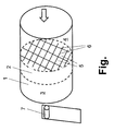
- the Fig. Shows an arrangement comprising a conduit 1 and a flow straightener 2, wherein the flow rectifier 2 is installed in the conduit to impart a flow of gas after flowing through the flow straightener 2 on a downstream side 3 within the conduit 1 a uniform flow profile.
- the flow rectifier 2 is flowed on the upstream side 4 of the gas.
- the flow rectifier 2 is formed as a honeycomb body having a plurality of channels 5, which are separated from each other by channel walls 6, wherein the honeycomb body is made of activated carbon or has activated carbon.
- the honeycomb body is made entirely of activated carbon.
- a plurality means more than two channels 5, preferably more than three, more than four, more than five, more than six, more than seven, more than eight, more than nine or more than ten channels 5.
- an air mass sensor 7 is arranged on the downstream side 3.
- an unillustrated engine of a motor vehicle is arranged, from which combustion gases diffuse back to the flow straightener 2.
- an air conditioning system can be arranged on the downstream side 3.
Landscapes
- Engineering & Computer Science (AREA)
- Chemical & Material Sciences (AREA)
- Mechanical Engineering (AREA)
- General Engineering & Computer Science (AREA)
- Analytical Chemistry (AREA)
- Chemical Kinetics & Catalysis (AREA)
- Combustion & Propulsion (AREA)
- Fluid Mechanics (AREA)
- Physics & Mathematics (AREA)
- General Physics & Mathematics (AREA)
- Oil, Petroleum & Natural Gas (AREA)
- General Chemical & Material Sciences (AREA)
- Organic Chemistry (AREA)
- Inorganic Chemistry (AREA)
- Separation Of Gases By Adsorption (AREA)
- Solid-Sorbent Or Filter-Aiding Compositions (AREA)
Abstract
Eine Anordnung, umfassend eine Leitung (1) und einen Strömungsgleichrichter (2), wobei der Strömungsgleichrichter (2) in die Leitung (1) eingebaut ist, um einem strömenden Gas nach Durchströmen des Strömungsgleichrichters (2) auf einer Abströmseite (3) innerhalb der Leitung (1) ein vergleichmäßigtes Strömungsprofil zu verleihen, ist im Hinblick auf die Aufgabe, eine Anordnung anzugeben, welche bei teilearmem und kompaktem Aufbau erlaubt, ein strömendes Gas einerseits im Hinblick auf sein Strömungsprofil zu vergleichmäßigen und andererseits Bestandteile eines Gases zu adsorbieren, dadurch gekennzeichnet, dass der Strömungsgleichrichter (2) als Wabenkörper ausgebildet ist, der eine Vielzahl von Kanälen (5) aufweist, die von einander durch Kanalwände (6) abgetrennt sind, wobei der Wabenkörper aus Aktivkohle gefertigt ist oder Aktivkohle aufweist.
Description
- Die Erfindung betrifft eine Anordnung gemäß dem Oberbegriff des Patentanspruchs 1 und eine Verwendung eines Strömungsgleichrichters.
- Es ist bereits bekannt, Strömungsgleichrichter in einer gasdurchströmten Leitung anzuordnen, um ein Strömungsprofil über einen durchströmten Querschnitt zu vergleichmäßigen. Daher umfassen übliche Anordnungen zumindest eine Leitung und einen Strömungsgleichrichter, wobei der Strömungsgleichrichter in die Leitung eingebaut ist, um einem strömenden Gas nach Durchströmen des Strömungsgleichrichters auf einer Abströmseite innerhalb der Leitung ein vergleichmäßigtes Strömungsprofil zu verleihen.
- Strömungsgleichrichter des Stands der Technik sind häufig aus Kunststoff oder Metall hergestellt. Üblicherweise werden hierbei die Funktionen der Strömungsgleichrichtung und Adsorption durch zwei verschiedene Bauteile ausgeführt, welche räumlich voneinander getrennt sind. Hierdurch ist für diese zwei Bauteile ein großer Platzbedarf in einem Leitungssystem zur Luftführung erforderlich.
- Der Erfindung liegt daher die Aufgabe zu Grunde, eine Anordnung anzugeben, welche bei teilearmem und kompaktem Aufbau erlaubt, ein strömendes Gas einerseits im Hinblick auf sein Strömungsprofil zu vergleichmäßigen und andererseits Bestandteile eines Gases zu adsorbieren.
- Erfindungsgemäß wird die voranstehende Aufgabe mit den Merkmalen der Patentansprüche 1 und 6 gelöst.
- Erfindungsgemäß ist erkannt worden, dass ein Strömungsgleichrichter zugleich als Adsorptionsfilterelement verwendet werden kann. Dabei werden beide Funktionen, nämlich Strömungsgleichrichtung und Adsorption, durch ein Bauteil ausgeführt.
- Erfindungsgemäß ist auch erkannt worden, dass als Strömungsgleichrichter ein Wabenkörper verwendet werden kann, der eine Vielzahl von Kanälen aufweist, die voneinander durch Kanalwände abgetrennt sind, wobei der Wabenkörper aus Aktivkohle gefertigt ist oder Aktivkohle aufweist. Der Strömungsgleichrichter ist als Wabenkörper aufgebaut, so dass über die Wabenstruktur, nämlich über Wanddicken und Wandabstände, die Gleichrichterfunktion variabel eingestellt werden kann. Insbesondere ist der Wabenkörper vollständig aus einem Material hergestellt, welches mehrheitlich aus Aktivkohle besteht, oder er besteht aus einem mit Aktivkohle beschichteten Substrat. Die Aktivkohle oder Aktivkohlebeschichtung erfüllt die Funktion, Kohlenwasserstoffe zu adsorbieren.
- Erfindungsgemäß ist hierbei konkret erkannt worden, dass zwei Funktionen durch ein kompaktes Bauteil erfüllt werden können. Erfindungsgemäß ist eine kostengünstige Lösung angegeben, welche den beiden Anforderungen Strömungsgleichrichtung und Gasadsorption gerecht wird.
- Folglich ist die eingangs genannte Aufgabe gelöst.
- Der Wabenkörper könnte vollständig aus Aktivkohle gefertigt sein. Der Strömungsgleichrichter in der Ausgestaltung als Wabenkörper aus Aktivkohle besitzt den Vorteil, dass er aufgrund seines Herstellverfahrens keine Aktivkohlepartikeln emittiert und daher auch vorteilhaft als Adsorptionsfilterelement verwendet werden kann.
- Auf der Abströmseite könnte ein Luftmassensensor angeordnet sein. Hierdurch wird ein Strömungsgleichrichter realisiert, der die Aufgabe hat, die Luftgeschwindigkeiten nach Betrag und Richtung zu vergleichmäßigen, so dass zum Beispiel in einem Motorluftansaugtrakt ein dem Strömungsgleichrichter nachgeschalteter Luftmassensensor in die Lage versetzt wird, mit sehr geringen Schwankungen die lokale Luftgeschwindigkeit zu messen. Die Werte, die von dem Luftmassensensor an einem bestimmten Ort erfasst werden, sind durch die Vergleichmäßigung des Luftgeschwindigkeitsprofils relativ repräsentativ für andere Orte nach dem Strömungsgleichrichter, an denen keine Luftmassensensoren vorgesehen sind.
- Vor diesem Hintergrund könnte auf der Abströmseite ein Motor eines Kraftfahrzeugs angeordnet sein, von welchem bei Stillstand des Kraftfahrzeuges Verbrennungsgase zum Strömungsgleichrichter zurück diffundieren. Eine zweite Funktion des Strömungsgleichrichters ist es, die nach dem Abschalten des Motors, nämlich eines Verbrennungsmotors, vom Motorraum eines Kraftfahrzeugs über eine Luftansaugstrecke zurückströmenden Kohlenwasserstoffe zu adsorbieren, so dass ein Austreten in die Umwelt verhindert wird. Der Wabenkörper aus Aktivkohle, der in einem Motorluftansaugtrakt eines Kraftfahrzeugmotors während des Motorbetriebes als Strömungsgleichrichter genutzt wird, kann zusätzlich bei Motorstillstand als Adsorptionsfilterelement für die zurückströmenden Kohlenwasserstoffe aus dem Motorraum verwendet werden. Er trägt dadurch zur Erfüllung der LEV III Anforderungen in den USA bei. Vorteilhaft ist der Wabenkörper in dieser Anwendung Strömungsgleichrichter und Adsorptionsfilterelement in einem Bauteil.
- LEV Standard ist eine Abkürzung für Low Emission Vehicle Standard (dt.: Fahrzeug mit geringen Emissionen Vorschrift). Diese wurde 1996 im US-Bundesstaat Kalifornien eingeführt. Heute ist das Programm in der 3. Stufe gültig, deshalb wird in dieser Schrift von LEV III gesprochen.
- LEV III betrifft Fahrzeuge der Modelljahre 2015 bis 2025. Der LEV III Standard wurde inzwischen in 12 weitere US-Bundesstaaten übernommen und wird im Jahre 2017 auch in Südkorea eingeführt.
- Der LEV III Standard gibt Grenzwerte für flüchtige Kohlenwasserstoffe vor, die ein Fahrzeug im Stillstand in einem bestimmten Zeitraum abgeben darf. Die Einhaltung dieser Grenzwerte muss vom Fahrzeughersteller nachgewiesen werden, um eine Zulassung in den betroffenen US-Bundestaaten zu bekommen.
- Der Wabenkörper aus Aktivkohle zeigt gegenüber herkömmlichen Adsorptionsfilterelementen, die zur Erfüllung der LEV III Anforderungen eingesetzt werden, den Vorteil, dass er als sogenanntes Full-Flow-Adsorptionsfilterelement eine um mindestens 50% reduzierte Druckdifferenz gegenüber einem herkömmlichen Full-Flow-Adsorptionsfilterelement besitzt.
- Herkömmliche Full-Flow-Adsorptionsfilterelemente für LEV III Anforderungen sind z.B. Faltenfilterelemente. Herkömmliche Faltenfilterelemente zur Adsorption werden üblicherweise als Laminat hergestellt, welches Aktivkohlepartikel zwischen Trägermaterialien einbindet. Diese Aktivkohlepartikel können sich bei Full-Flow-Anwendungen lösen und mit dem Luftstrom ausgetragen werden.
- Auf der Abströmseite des Strömungsgleichrichters könnte ein Wärmetauscher einer Klimaanlage angeordnet sein. Eine weitere Anwendung des genannten Strömungsgleichrichters besteht darin, den Zuluftstrom einer Klimaanlage nach Betrag und Richtung zu vergleichmäßigen und gleichzeitig von Kohlenwasserstoffen zu reinigen. Vorteilhaft werden die Strömungsgleichrichtung und die Gasadsorption innerhalb einer Klimaanlage gleichzeitig von einem Bauteil erbracht. Bei Positionierung des Strömungsgleichrichters vor dem Wärmetauscher innerhalb einer Klimaanlage, wird die Effizienz, nämlich der Wirkungsgrad, des Wärmetauschers, gesteigert, da durch den Strömungsgleichrichter sichergestellt ist, dass der Luftstrom eine größere Fläche des Wärmetauschers erreicht. Dadurch wird der Wirkungsgrad des Wärmetauschers gesteigert. Herkömmliche Adsorptionsfilterelemente in Klimaanlagen werden üblicherweise als Faltenfilterelemente aus einem Laminat hergestellt, welches Aktivkohlepartikel zwischen Trägermaterialien einbindet. Diese Aktivkohlepartikel können sich im Betrieb lösen und mit dem Luftstrom ausgetragen werden.
- In der Zeichnung zeigt die
- Fig.
- eine Anordnung, welche einen Strömungsgleichrichter aufweist.
- Die Fig. zeigt eine Anordnung, umfassend eine Leitung 1 und einen Strömungsgleichrichter 2, wobei der Strömungsgleichrichter 2 in die Leitung eingebaut ist, um einem strömenden Gas nach Durchströmen des Strömungsgleichrichters 2 auf einer Abströmseite 3 innerhalb der Leitung 1 ein vergleichmäßigtes Strömungsprofil zu verleihen. Der Strömungsgleichrichter 2 wird auf der Anströmseite 4 vom Gas angeströmt.
- Der Strömungsgleichrichter 2 ist als Wabenkörper ausgebildet, der eine Vielzahl von Kanälen 5 aufweist, die voneinander durch Kanalwände 6 abgetrennt sind, wobei der Wabenkörper aus Aktivkohle gefertigt ist oder Aktivkohle aufweist. Der Wabenkörper ist vollständig aus Aktivkohle gefertigt.
- Unter einer Vielzahl werden mehr als zwei Kanäle 5, bevorzugt mehr als drei, mehr als vier, mehr als fünf, mehr als sechs, mehr als sieben, mehr als acht, mehr als neun oder mehr als zehn Kanäle 5 verstanden.
- Auf der Abströmseite 3 ist ein Luftmassensensor 7 angeordnet. Auf der Abströmseite 3 ist ein nicht gezeigter Motor eines Kraftfahrzeugs angeordnet, von welchem Verbrennungsgase zum Strömungsgleichrichter 2 zurück diffundieren.
- Auf der Abströmseite 3 kann ein nicht gezeigter Wärmetauscher einer Klimaanlage angeordnet sein.
Claims (7)
- Anordnung, umfassend eine Leitung (1) und einen Strömungsgleichrichter (2), wobei der Strömungsgleichrichter (2) in die Leitung (1) eingebaut ist, um einem strömenden Gas nach Durchströmen des Strömungsgleichrichters (2) auf einer Abströmseite (3) innerhalb der Leitung (1) ein vergleichmäßigtes Strömungsprofil zu verleihen,
dadurch gekennzeichnet, dass der Strömungsgleichrichter (2) als Wabenkörper ausgebildet ist, der eine Vielzahl von Kanälen (5) aufweist, die voneinander durch Kanalwände (6) abgetrennt sind, wobei der Wabenkörper aus Aktivkohle gefertigt ist oder Aktivkohle aufweist. - Anordnung nach Anspruch 1, dadurch gekennzeichnet, dass der Wabenkörper vollständig aus Aktivkohle gefertigt ist.
- Anordnung nach Anspruch 1 oder 2, dadurch gekennzeichnet, dass auf der Abströmseite (3) ein Luftmassensensor (7) angeordnet ist.
- Anordnung nach einem der voranstehenden Ansprüche, dadurch gekennzeichnet, dass auf der Abströmseite (3) ein Motor eines Kraftfahrzeugs angeordnet ist, von welchem Verbrennungsgase zum Strömungsgleichrichter (2) zurück diffundieren.
- Anordnung nach einem der voranstehenden Ansprüche, dadurch gekennzeichnet, dass auf der Abströmseite (3) ein Wärmetauscher einer Klimaanlage angeordnet ist.
- Verwendung eines Strömungsgleichrichters (2) zugleich als Adsorptionsfilterelement.
- Verwendung nach Anspruch 6, dadurch gekennzeichnet, dass der Strömungsgleichrichter (2) in einer Anordnung nach einem der Ansprüche 1 bis 5 verwendet wird.
Priority Applications (3)
| Application Number | Priority Date | Filing Date | Title |
|---|---|---|---|
| EP15163346.8A EP3081909A1 (de) | 2015-04-13 | 2015-04-13 | Anordnung mit einem strömungsgleichrichter |
| KR1020160043409A KR20160122072A (ko) | 2015-04-13 | 2016-04-08 | 유동 정류기를 갖춘 어셈블리 |
| US15/095,194 US20160298663A1 (en) | 2015-04-13 | 2016-04-11 | Arrangement with a flow rectifier |
Applications Claiming Priority (1)
| Application Number | Priority Date | Filing Date | Title |
|---|---|---|---|
| EP15163346.8A EP3081909A1 (de) | 2015-04-13 | 2015-04-13 | Anordnung mit einem strömungsgleichrichter |
Publications (1)
| Publication Number | Publication Date |
|---|---|
| EP3081909A1 true EP3081909A1 (de) | 2016-10-19 |
Family
ID=52997857
Family Applications (1)
| Application Number | Title | Priority Date | Filing Date |
|---|---|---|---|
| EP15163346.8A Withdrawn EP3081909A1 (de) | 2015-04-13 | 2015-04-13 | Anordnung mit einem strömungsgleichrichter |
Country Status (3)
| Country | Link |
|---|---|
| US (1) | US20160298663A1 (de) |
| EP (1) | EP3081909A1 (de) |
| KR (1) | KR20160122072A (de) |
Cited By (3)
| Publication number | Priority date | Publication date | Assignee | Title |
|---|---|---|---|---|
| EP3372294A1 (de) * | 2017-03-06 | 2018-09-12 | Carl Freudenberg KG | Filteranordnung für eine mobile einrichtung |
| EE01508U1 (et) * | 2019-07-03 | 2020-08-17 | Enteh Engineering As | Ebaühtlaste ja mittestatsionaarsete kiirusväljade mahtühtlusti |
| US20210060472A1 (en) * | 2019-08-30 | 2021-03-04 | Indufil BV | Flow optimized filter |
Families Citing this family (3)
| Publication number | Priority date | Publication date | Assignee | Title |
|---|---|---|---|---|
| ES2714366T3 (es) * | 2015-12-21 | 2019-05-28 | Fydec Holding Sa | Dispositivo de dosificación de cantidades mínimas, en particular para aplicaciones farmacéuticas, así como el proceso de dosificación de cantidades mínimas de polvo |
| JP7027942B2 (ja) * | 2018-02-22 | 2022-03-02 | トヨタ自動車株式会社 | 蒸発燃料処理装置 |
| CN116899066A (zh) * | 2023-06-19 | 2023-10-20 | 南京舒普思达医疗设备有限公司 | 一种氧气组件及使用该组件的呼吸机 |
Citations (3)
| Publication number | Priority date | Publication date | Assignee | Title |
|---|---|---|---|---|
| GB2402971A (en) * | 2003-06-18 | 2004-12-22 | Visteon Global Tech Inc | Flow conditioning device for i.c. engine air intake |
| DE102004002774B3 (de) * | 2003-12-18 | 2005-05-19 | Helsa-Werke Helmut Sandler Gmbh & Co. Kg | Sorptiver Kanalfilter |
| DE102010062892A1 (de) * | 2010-12-13 | 2012-06-14 | Robert Bosch Gmbh | Strömungsgitter zum Einsatz in einem Strömungsrohr eines strömenden fluiden Mediums |
-
2015
- 2015-04-13 EP EP15163346.8A patent/EP3081909A1/de not_active Withdrawn
-
2016
- 2016-04-08 KR KR1020160043409A patent/KR20160122072A/ko not_active Ceased
- 2016-04-11 US US15/095,194 patent/US20160298663A1/en not_active Abandoned
Patent Citations (3)
| Publication number | Priority date | Publication date | Assignee | Title |
|---|---|---|---|---|
| GB2402971A (en) * | 2003-06-18 | 2004-12-22 | Visteon Global Tech Inc | Flow conditioning device for i.c. engine air intake |
| DE102004002774B3 (de) * | 2003-12-18 | 2005-05-19 | Helsa-Werke Helmut Sandler Gmbh & Co. Kg | Sorptiver Kanalfilter |
| DE102010062892A1 (de) * | 2010-12-13 | 2012-06-14 | Robert Bosch Gmbh | Strömungsgitter zum Einsatz in einem Strömungsrohr eines strömenden fluiden Mediums |
Cited By (4)
| Publication number | Priority date | Publication date | Assignee | Title |
|---|---|---|---|---|
| EP3372294A1 (de) * | 2017-03-06 | 2018-09-12 | Carl Freudenberg KG | Filteranordnung für eine mobile einrichtung |
| US10843114B2 (en) | 2017-03-06 | 2020-11-24 | Carl Freudenberg Kg | Filter arrangement for a mobile device |
| EE01508U1 (et) * | 2019-07-03 | 2020-08-17 | Enteh Engineering As | Ebaühtlaste ja mittestatsionaarsete kiirusväljade mahtühtlusti |
| US20210060472A1 (en) * | 2019-08-30 | 2021-03-04 | Indufil BV | Flow optimized filter |
Also Published As
| Publication number | Publication date |
|---|---|
| US20160298663A1 (en) | 2016-10-13 |
| KR20160122072A (ko) | 2016-10-21 |
Similar Documents
| Publication | Publication Date | Title |
|---|---|---|
| EP3081909A1 (de) | Anordnung mit einem strömungsgleichrichter | |
| WO2016058743A1 (de) | Drucksensor zur erfassung eines drucks eines fluiden mediums | |
| DE202009009760U1 (de) | Modular aufgebaute Einheit | |
| EP2934982B1 (de) | Klimatisierungsanordnung für ein schienenfahrzeug | |
| DE202008018286U1 (de) | Luftauslass | |
| WO2018108746A1 (de) | Vorrichtung zum befeuchten eines luftstroms | |
| DE102008025959A1 (de) | Vorrichtung zur Verbindung von zwei Rohrleitungselementen und einer Blende in einer Flugzeugklimatisierungsanlage | |
| DE10230044A1 (de) | Schalldämpfer | |
| DE102017222752A1 (de) | Filteranordnung für eine Belüftungs- oder Klimaanlage | |
| WO2003069284A1 (de) | Strömungsgleichrichter für einen luftmassensensor | |
| DE102011100014A1 (de) | Schalldämpfer | |
| DE102014209452A1 (de) | Klimaanlage mit Bypassvorrichtung | |
| DE102005026709A1 (de) | Strömungssensor | |
| DE102007014003B4 (de) | Rohrverbindungsvorrichtung | |
| EP3737919B1 (de) | Messanordnung zur bestimmung eines parameters eines durch einen fluidströmungskanal strömenden fluiden mediums sowie fluidströmungskanal mit einer solchen messanordnung | |
| DE102018109858A1 (de) | Klimadüse mit Coanda-Effekt | |
| DE102007039587A1 (de) | Luftauslasseinrichtung für Fahrzeuge | |
| DE102012207198B4 (de) | Vorrichtung zur Verringerung der Lärmemission von Luftansaugrohren | |
| EP2002411B1 (de) | Rauchmelder | |
| EP3698075B1 (de) | Steuerschrank | |
| EP1481830B1 (de) | Belüftungsvorrichtung, insbesondere für ein Kraftfahrzeug | |
| EP1674775B1 (de) | Bausatz zur Bereitstellung von Stellgeräten | |
| EP1571021B1 (de) | Heizluftein- und Ausströmbaugruppe für ein Heizgerät | |
| DE102009008219A1 (de) | Ausströmdüse für eine Lüftungsvorrichtung eines Fahrzeuges | |
| DE102022119623A1 (de) | Belüftungsvorrichtung für ein Kraftfahrzeug sowie hiermit ausgestattetes Kraftfahrzeug |
Legal Events
| Date | Code | Title | Description |
|---|---|---|---|
| PUAI | Public reference made under article 153(3) epc to a published international application that has entered the european phase |
Free format text: ORIGINAL CODE: 0009012 |
|
| AK | Designated contracting states |
Kind code of ref document: A1 Designated state(s): AL AT BE BG CH CY CZ DE DK EE ES FI FR GB GR HR HU IE IS IT LI LT LU LV MC MK MT NL NO PL PT RO RS SE SI SK SM TR |
|
| AX | Request for extension of the european patent |
Extension state: BA ME |
|
| STAA | Information on the status of an ep patent application or granted ep patent |
Free format text: STATUS: THE APPLICATION IS DEEMED TO BE WITHDRAWN |
|
| 18D | Application deemed to be withdrawn |
Effective date: 20170420 |