EP3081874A1 - Building with demand-controlled heat exchange system for ventilation and heat exchange system - Google Patents
Building with demand-controlled heat exchange system for ventilation and heat exchange system Download PDFInfo
- Publication number
- EP3081874A1 EP3081874A1 EP16164502.3A EP16164502A EP3081874A1 EP 3081874 A1 EP3081874 A1 EP 3081874A1 EP 16164502 A EP16164502 A EP 16164502A EP 3081874 A1 EP3081874 A1 EP 3081874A1
- Authority
- EP
- European Patent Office
- Prior art keywords
- secondary air
- discharge
- flow passage
- supply
- heat exchange
- Prior art date
- Legal status (The legal status is an assumption and is not a legal conclusion. Google has not performed a legal analysis and makes no representation as to the accuracy of the status listed.)
- Granted
Links
- 238000009423 ventilation Methods 0.000 title description 4
- 238000007599 discharging Methods 0.000 claims description 2
- 230000001105 regulatory effect Effects 0.000 description 5
- 238000009434 installation Methods 0.000 description 4
- 238000001816 cooling Methods 0.000 description 2
- 238000010438 heat treatment Methods 0.000 description 2
- 230000008054 signal transmission Effects 0.000 description 2
- 238000004519 manufacturing process Methods 0.000 description 1
- 230000000717 retained effect Effects 0.000 description 1
- 239000000725 suspension Substances 0.000 description 1
Images


Classifications
-
- F—MECHANICAL ENGINEERING; LIGHTING; HEATING; WEAPONS; BLASTING
- F24—HEATING; RANGES; VENTILATING
- F24F—AIR-CONDITIONING; AIR-HUMIDIFICATION; VENTILATION; USE OF AIR CURRENTS FOR SCREENING
- F24F12/00—Use of energy recovery systems in air conditioning, ventilation or screening
- F24F12/001—Use of energy recovery systems in air conditioning, ventilation or screening with heat-exchange between supplied and exhausted air
- F24F12/006—Use of energy recovery systems in air conditioning, ventilation or screening with heat-exchange between supplied and exhausted air using an air-to-air heat exchanger
-
- F—MECHANICAL ENGINEERING; LIGHTING; HEATING; WEAPONS; BLASTING
- F24—HEATING; RANGES; VENTILATING
- F24F—AIR-CONDITIONING; AIR-HUMIDIFICATION; VENTILATION; USE OF AIR CURRENTS FOR SCREENING
- F24F13/00—Details common to, or for air-conditioning, air-humidification, ventilation or use of air currents for screening
- F24F13/02—Ducting arrangements
- F24F13/0236—Ducting arrangements with ducts including air distributors, e.g. air collecting boxes with at least three openings
-
- F—MECHANICAL ENGINEERING; LIGHTING; HEATING; WEAPONS; BLASTING
- F24—HEATING; RANGES; VENTILATING
- F24F—AIR-CONDITIONING; AIR-HUMIDIFICATION; VENTILATION; USE OF AIR CURRENTS FOR SCREENING
- F24F7/00—Ventilation
- F24F2007/001—Ventilation with exhausting air ducts
- F24F2007/002—Junction box, e.g. for ducts from kitchen, toilet or bathroom
-
- Y—GENERAL TAGGING OF NEW TECHNOLOGICAL DEVELOPMENTS; GENERAL TAGGING OF CROSS-SECTIONAL TECHNOLOGIES SPANNING OVER SEVERAL SECTIONS OF THE IPC; TECHNICAL SUBJECTS COVERED BY FORMER USPC CROSS-REFERENCE ART COLLECTIONS [XRACs] AND DIGESTS
- Y02—TECHNOLOGIES OR APPLICATIONS FOR MITIGATION OR ADAPTATION AGAINST CLIMATE CHANGE
- Y02B—CLIMATE CHANGE MITIGATION TECHNOLOGIES RELATED TO BUILDINGS, e.g. HOUSING, HOUSE APPLIANCES OR RELATED END-USER APPLICATIONS
- Y02B30/00—Energy efficient heating, ventilation or air conditioning [HVAC]
- Y02B30/56—Heat recovery units
Definitions
- the invention concerns a building comprising several rooms, of which one room is connected to a secondary air supply duct and a secondary air discharge duct, and of which another room is connected to another secondary air supply duct and another secondary air discharge duct, a heat exchange system which is connected to the secondary air supply ducts and the secondary air discharge ducts and to a main air supply duct and a main air discharge duct, which heat exchange system comprises a housing which contains a supply flow passage and a discharge flow passage, a heat exchanger by means of which the supply flow passage and the discharge flow passage are in a heat-exchanging relationship to each other, wherein the main air supply duct is connected to one end of the supply flow passage, at the other end of which supply flow passage at least two secondary air supply ducts are connected, the main air discharge duct is connected to one end of the discharge flow passage, to the other end of which discharge flow passage at least two secondary air discharge ducts are connected, a booster for supplying air to the rooms through the main air supply duct via the supply flow passage and the secondary
- Such a building is known and has the advantage that the energy for heating and/or cooling the various rooms thereof can be utilised more efficiently.
- the discharged air emits energy to the supplied air at the heat exchanger so that energy for heating or cooling the rooms can be saved.
- the air which flows through the heat exchange system must be distributed evenly to a greater or lesser extent over the various rooms.
- the need for the supply and discharge of air may differ greatly from room to room. This is affected by the occupation of the rooms, the moisture production, the incident sunlight and similar.
- the set distribution of the supply to the various rooms and the discharge from the various rooms cannot be adapted, or can scarcely be adapted, to the actual requirements.
- One aim of the invention is therefore to create a building in which the ventilation is improved. Another aim is to create a building in which the ventilation can be adjusted room by room. A further aim is to create a building in which the heat exchange system can be adapted flexibly. Yet another aim is to create a building in which firstly the energy demand can be handled efficiently, and in which secondly the supply/discharge of air can be regulated room by room.
- the flow regulator or regulators located in the supply and/or discharge air flow offers/offer the possibility of adapting the air flow room by room, while the exchange of heat between the supplied and discharged air is retained. These functions are all accommodated in the heat exchange system so that a compact design is obtained which contains all the desired functions. This allows simple installation.
- the flow regulator is provided in the housing, there are no visible connections between the flow regulators and the secondary supply and/or discharge ducts, nor are there any visible cable connections from the flow regulator(s) to the control system.
- the heat exchange system with the flow regulator(s) can be moved and connected as a whole. In addition, on overhaul of the system, in particular of the flow regulators, it is not necessary to decouple the secondary supply and/or discharge ducts.
- a room may mean a spacial zone with one or more room sections or chambers. In this way, the supply/discharge of air can be regulated for each room and hence also for the one or more room sections of this room.
- the flow regulator may be contained in just one secondary air supply duct and/or in just one secondary air discharge duct.
- the embodiment comprises several flow regulators.
- one flow regulator may be located in the supply flow passage between the heat exchanger and one of the secondary air supply ducts, and another flow regulator may be located between the heat exchanger and the other of the secondary air supply ducts, for individual regulation of the air flow through said one secondary air supply duct independently of the regulation of the air flow through said other secondary air supply duct.
- a flow regulator may be provided which is located between the heat exchanger and one of the secondary air discharge ducts, and another flow regulator which is located between the heat exchanger and another of the secondary air discharge ducts, for individual regulation of the air flow through said one secondary air discharge duct independently of regulation of the air flow through said other secondary air discharge duct.
- a flow regulator is provided for each secondary air supply and/or discharge duct.
- at least one flow regulator may be provided for two secondary air supply and/or discharge ducts.
- the ventilation can be adapted in the desired manner.
- This may be done in different ways.
- One example is regulation by means of a control panel located in the room concerned.
- Automatic regulation is however preferred in which a measuring system for measuring a property of the air is provided at least in the supply flow passage and/or discharge flow passage.
- a measuring system may for example comprise a sensor unit for measuring the C02 content, the relative humidity and similar of the air.
- a control system may be provided for regulating the flow on the basis of the property measured by the measuring system.
- a flow regulator may here form part of a cassette, in which case the housing is provided by a cassette chamber in which the cassette is received.
- This cassette chamber may have a guide by means of which the cassette can be guided into the cassette chamber or out of the cassette chamber respectively.
- the flow regulator can be fitted or replaced very easily. It is also possible to install the flow regulator afterwards.
- the cassette guide is oriented transversely to the air flow direction through the supply flow passage and/or the discharge flow passage.
- the (guide of the) cassette chamber preferably has an opening which opens on the outside of the housing and is closed there by a cover.
- the flow regulator is thus firstly easily accessible from outside and secondly well protected from external influences by the cover. This could also cover the cables for the power supply, signal transmission and similar.
- several cassette chambers may be provided next to each other, which cassette chambers are closed by a common cover.
- the flow regulator is located in or inside the housing of the heat exchange system.
- This also includes a position of the flow regulator(s) in the wall of the housing.
- the flow regulators and the associated cassettes are thus located under the cover which closes the housing.
- the flow regulators with the associated measuring system and control systems are well protected from external influences without the need for supplementary measures.
- This has the advantage that the ducts can be connected directly to the housing, which is important if little space is available for the installation.
- the invention also concerns a heat exchange system for a building, comprising a housing which contains a supply flow passage and a discharge flow passage, a heat exchanger by means of which the supply flow passage and the discharge flow passage are in a heat-exchanging relationship to each other, a main air supply connection at one end of the supply flow passage, at the other end of which supply flow passage at least two secondary air supply connections are located, a main air discharge connection at one end of the discharge flow passage, at the other end of which discharge flow passage at least two secondary air discharge connections are located, a booster for ensuring the flow of air through the main air supply connection via the supply flow passage and the secondary air supply connections, and a second booster for ensuring the flow of air via the secondary air discharge connections, the discharge flow passage and the main air discharge connection.
- the heat exchange system according to the invention is however characterized in that the housing is provided with at least one flow regulator located between the heat exchanger and a secondary air supply connection, and/or a flow regulator located between the heat exchanger and a secondary air discharge connection.
- a flow regulator is provided for each secondary air supply and/or air discharge connection.
- at least one flow regulator may be provided for two secondary air supply and/or air discharge connections.
- a flow regulator may be placed in the supply flow passage, located between the heat exchanger and one of the secondary air supply connections, and another flow regulator is located between the heat exchanger and another of the secondary air supply connections, for the individual regulation of the air flow through said one secondary air supply connection independently of the regulation of the air flow through said other secondary air supply connection.
- a flow regulator is preferably placed in the discharge flow passage and is located between the heat exchanger and one of the secondary air discharge connections, and furthermore another flow regulator which is located between the heat exchanger and another of the second air discharge connections, for individual regulation of the air flow through said one secondary air discharge connection independently of the regulation of the air flow through said other secondary air discharge connection.
- the flow regulator may be provided at the site of one secondary air supply connection and/or at the site of one secondary air discharge connection.
- the heat exchange system may furthermore be configured in the same way as described above in connection with a building.
- the flow regulator is provided in the supply flow passage.
- the building shown in Figure 1 has several rooms or zones 1, 2 to which air can be supplied by the secondary air supply ducts 3, 4. Also, air can be discharged from a room via the secondary air discharge ducts 5, 6.
- the rooms or zones 1, 2 each comprise two room sections or chambers 1', 1", 2', 2".
- the air to be supplied is conducted into the building via the main air supply duct 7 and discharged therefrom via the main air discharge duct 8.
- the heat exchange system indicated as a whole with reference numeral 9 is placed between the path formed between the main air supply duct 8 and the secondary air supply ducts 3, 4 on one side, and the path formed between the main air discharge duct 8 and the secondary air discharge ducts 5, 6 on the other.
- FIG. 2 - 4 A first embodiment of the heat exchange system 9 is shown in Figures 2 - 4 .
- This heat exchange system has a housing, designated as a whole as 12, with a main air supply connection 10 to which the main air supply duct 7 of Figure 1 connects. Furthermore, the heat exchange system has a main air discharge connection 11 to which the main air discharge duct 8 connects. At the other end of the housing are several, in this exemplary embodiment two, secondary air supply connections 13 and two secondary air discharge connections 14.
- the supply flow passage 15 extends between the main air supply connection 10 and the secondary air supply connection 13.
- the discharge flow passage 16 extends between the secondary air discharge connections 14 and the main air discharge connection 11.
- the heat exchanger designated as a whole as 18 is placed in the supply flow passage 15 and discharge flow passage 17, and ensures that energy is exchanged between the supplied air and the discharged air.
- the air is supplied and discharged by means of the two boosters 19, one of which is placed in the supply flow passage 15 and the other in the discharge flow passage 16.
- the air flows to the various rooms or is extracted therefrom without further possibility of regulation.
- flow regulators 17 are placed in the secondary air supply connection 13.
- Each flow regulator is contained in a cassette 20, each of which in turn is held in a cassette chamber 21 located at or behind the corresponding secondary air supply connection 13.
- a cassette guide 22 is provided in each cassette chamber to facilitate the fitting or removal or replacement of such a cassette 20.
- Each cassette furthermore has a measuring system 23, which may for example comprise a sensor for measuring the CO2 value of the air, the humidity or similar.
- the measuring system 23 is placed on the flow regulator 17 itself, but it is also possible to place this elsewhere on the cassette or elsewhere in the supply flow passage 15, or to place a separate sensor in the room.
- a control system 24 is provided on the cassette 20 with which, on the basis of the data obtained by the measuring system 23, the flow regulator 17 can be set to the desired level.
- cassettes 20, cassette chambers 21 and cassette guides 22 are provided at the secondary air supply connections 24. All cassette chambers can be covered by the cover 28 with which the housing 12 as a whole is closed.
- the heat exchange system 9 has a housing 12 with two walls 26, 27 placed obliquely.
- the one wall 26 has two secondary air discharge connections 14.
- a distributor piece 25 is fitted on the second obliquely placed wall 27, and in total has four secondary air supply connections 13.
- a cassette 20 is arranged at each of the secondary air supply connections 14, wherein the cassette chambers 21 may be placed horizontally or vertically, depending on the orientation of the respective secondary air supply connection 13. These cassette chambers are also covered by a cover (not shown).
- FIG 7 shows a diagrammatic side view of a further embodiment of the heat exchange system 9, in an opened state.
- This heat exchange system 9 has a housing, designated as a whole as 12, with a main air supply connection 10 to which the main air supply duct 7 of Figure 1 connects. Furthermore, the heat exchange system 9 has a main air discharge connection 11 to which the main air discharge duct 8 connects. At the same end of the housing 12 are several, in the exemplary embodiment shown two, secondary air supply connections 13 and one secondary air discharge connection 14.
- the supply flow passage extends between the main air supply connection 10 and the secondary air supply connection 13.
- the discharge flow passage extends between the secondary air discharge connections 14 and the main discharge air connection 11.
- the heat exchanger designated as a whole as 18, is placed in this supply flow passage and discharge flow passage, and ensures that energy is exchanged between the supplied air and the discharged air.
- the air is supplied and discharged by means of two boosters 19 (only one shown in Figure 7 ), one of which is placed in the supply flow passage and the other in the discharge flow passage.
- a flow regulator 17 is placed in the secondary air supply connection 13.
- the flow regulator 17 is held in a cassette 20 which in turn is received in a cassette chamber 21, located at or behind the respective secondary air supply connection 13.
- one flow regulator 17 is provided per two secondary supply connections 13.
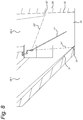
- FIG 8 shows a cross-section of a cassette for the heat exchange system in Figure 7 .
- the cassette 20 is provided with two cassette outlets 29 located next to each other, which connect to the respective secondary supply connections 13 when the cassette is introduced in the system 9, and an opposing cassette inlet 30 which connects to the supply flow passage of the system 9.
- the flow regulator or valve 17 is provided with a suspension point between the two cassette outlets 29. The valve 17 functions as a flow regulator for both cassette outlets 29 or secondary supply connections 13.
- the flow regulator or valve 17 may assume various positions for regulating the flow through the respective cassette outlets 29 or the secondary supply connections 13.
- the valve 17 allows air to flow through the cassette from the cassette inlet 30 through both a first cassette outlet 29.1 and a second cassette outlet 29.2.
- a first closed position 31" the valve 17 is oriented towards a first contact wall 31 of the cassette 20. A free end of the valve 17 then rests on the first contact wall 31 at a first contact point 31'.
- the first cassette outlet 29.1 is closed so that the air flow is now allowed only from the cassette inlet 30 to the second cassette outlet 29.2.
- valve 17 In a second closed position 32", the valve 17 is oriented towards a second contact wall 32 of the cassette 20. The free end of the valve 17 rests on the second contact wall 32 at a second contact point 32'. In the second closed position, the second cassette outlet 29.2 is closed so that the air flow is now allowed only from the cassette inlet 30 to the first cassette outlet 29.1.
- the air flow to the respective cassette outlets may be regulated further by orienting the valve 17 in any desired position between the first and second closed state.
- the valve 17 When the valve 17 is oriented closer to the first contact wall 31, the opening for air flow to the first cassette outlet 29.1 is smaller, so that the air flow through this cassette outlet will be reduced.
- the opening for air flow to the second cassette outlet 29.2 becomes larger, so that the air flow through the second cassette outlet will increase.
- the flap 17 is oriented more towards the second contact wall 32.
Landscapes
- Engineering & Computer Science (AREA)
- Chemical & Material Sciences (AREA)
- Combustion & Propulsion (AREA)
- Mechanical Engineering (AREA)
- General Engineering & Computer Science (AREA)
- Central Air Conditioning (AREA)
Abstract
Description
- The invention concerns a building comprising several rooms, of which one room is connected to a secondary air supply duct and a secondary air discharge duct, and of which another room is connected to another secondary air supply duct and another secondary air discharge duct, a heat exchange system which is connected to the secondary air supply ducts and the secondary air discharge ducts and to a main air supply duct and a main air discharge duct, which heat exchange system comprises a housing which contains a supply flow passage and a discharge flow passage, a heat exchanger by means of which the supply flow passage and the discharge flow passage are in a heat-exchanging relationship to each other, wherein the main air supply duct is connected to one end of the supply flow passage, at the other end of which supply flow passage at least two secondary air supply ducts are connected, the main air discharge duct is connected to one end of the discharge flow passage, to the other end of which discharge flow passage at least two secondary air discharge ducts are connected, a booster for supplying air to the rooms through the main air supply duct via the supply flow passage and the secondary air supply ducts, and a second booster for discharging air from the rooms via the secondary air discharge ducts, the air discharge passage and the main air discharge duct.
- Such a building is known and has the advantage that the energy for heating and/or cooling the various rooms thereof can be utilised more efficiently. The discharged air emits energy to the supplied air at the heat exchanger so that energy for heating or cooling the rooms can be saved.
- The air which flows through the heat exchange system must be distributed evenly to a greater or lesser extent over the various rooms. In practice however, it is found that the need for the supply and discharge of air may differ greatly from room to room. This is affected by the occupation of the rooms, the moisture production, the incident sunlight and similar. In known buildings however, the set distribution of the supply to the various rooms and the discharge from the various rooms cannot be adapted, or can scarcely be adapted, to the actual requirements.
- One aim of the invention is therefore to create a building in which the ventilation is improved. Another aim is to create a building in which the ventilation can be adjusted room by room. A further aim is to create a building in which the heat exchange system can be adapted flexibly. Yet another aim is to create a building in which firstly the energy demand can be handled efficiently, and in which secondly the supply/discharge of air can be regulated room by room. These and other aims are achieved in that the housing is provided with at least one flow regulator which is located between the heat exchanger and a secondary air supply duct and/or at least one flow regulator which is located between the heat exchanger and a secondary air discharge duct. The flow regulator or regulators located in the supply and/or discharge air flow offers/offer the possibility of adapting the air flow room by room, while the exchange of heat between the supplied and discharged air is retained. These functions are all accommodated in the heat exchange system so that a compact design is obtained which contains all the desired functions. This allows simple installation. In addition, because the flow regulator is provided in the housing, there are no visible connections between the flow regulators and the secondary supply and/or discharge ducts, nor are there any visible cable connections from the flow regulator(s) to the control system. Furthermore, the heat exchange system with the flow regulator(s) can be moved and connected as a whole. In addition, on overhaul of the system, in particular of the flow regulators, it is not necessary to decouple the secondary supply and/or discharge ducts.
- A room may mean a spacial zone with one or more room sections or chambers. In this way, the supply/discharge of air can be regulated for each room and hence also for the one or more room sections of this room.
- As already mentioned, the flow regulator may be contained in just one secondary air supply duct and/or in just one secondary air discharge duct. Preferably however, the embodiment comprises several flow regulators. For example, one flow regulator may be located in the supply flow passage between the heat exchanger and one of the secondary air supply ducts, and another flow regulator may be located between the heat exchanger and the other of the secondary air supply ducts, for individual regulation of the air flow through said one secondary air supply duct independently of the regulation of the air flow through said other secondary air supply duct.
- Furthermore, in the discharge flow passage a flow regulator may be provided which is located between the heat exchanger and one of the secondary air discharge ducts, and another flow regulator which is located between the heat exchanger and another of the secondary air discharge ducts, for individual regulation of the air flow through said one secondary air discharge duct independently of regulation of the air flow through said other secondary air discharge duct.
- In one embodiment, a flow regulator is provided for each secondary air supply and/or discharge duct. Alternatively, at least one flow regulator may be provided for two secondary air supply and/or discharge ducts.
- In these embodiments, for each room for which the secondary air supply duct or secondary air discharge duct has a flow regulator, the ventilation can be adapted in the desired manner. This may be done in different ways. One example is regulation by means of a control panel located in the room concerned. Automatic regulation is however preferred in which a measuring system for measuring a property of the air is provided at least in the supply flow passage and/or discharge flow passage. Such a measuring system may for example comprise a sensor unit for measuring the C02 content, the relative humidity and similar of the air. Furthermore, a control system may be provided for regulating the flow on the basis of the property measured by the measuring system.
- As already stated, it may be desirable to be able to adapt the heat exchange systems flexibly. For example, it may be preferable to create a general embodiment which has the possibility of allowing regulation per secondary air supply duct or per secondary air discharge duct as required, while others may remain open. In an efficient embodiment, a flow regulator may here form part of a cassette, in which case the housing is provided by a cassette chamber in which the cassette is received. This cassette chamber may have a guide by means of which the cassette can be guided into the cassette chamber or out of the cassette chamber respectively. In such an embodiment, the flow regulator can be fitted or replaced very easily. It is also possible to install the flow regulator afterwards.
- Preferably, the cassette guide is oriented transversely to the air flow direction through the supply flow passage and/or the discharge flow passage. The (guide of the) cassette chamber preferably has an opening which opens on the outside of the housing and is closed there by a cover. The flow regulator is thus firstly easily accessible from outside and secondly well protected from external influences by the cover. This could also cover the cables for the power supply, signal transmission and similar. In an efficient embodiment, several cassette chambers may be provided next to each other, which cassette chambers are closed by a common cover.
- In particular, the flow regulator is located in or inside the housing of the heat exchange system. This also includes a position of the flow regulator(s) in the wall of the housing. The flow regulators and the associated cassettes are thus located under the cover which closes the housing. In this way, the flow regulators with the associated measuring system and control systems are well protected from external influences without the need for supplementary measures. Thus there are no parts which are located outside the housing or which are located between the secondary air supply ducts and the secondary air discharge ducts. This has the advantage that the ducts can be connected directly to the housing, which is important if little space is available for the installation. Reference is made to the prior art, consisting of a heat exchange system in which the flow regulators are arranged in the connected ducts. Such installations have relatively large dimensions, while the electrical lines for the power supply to the valves and for signal transmission must be installed afterwards. Because of the many separate components constituting the known systems, the dimensions of these systems are relatively large. Furthermore, the fitting of such an installation is labour-intensive. The various components such as valves, measuring systems and similar are less well protected. The invention also concerns a heat exchange system for a building, comprising a housing which contains a supply flow passage and a discharge flow passage, a heat exchanger by means of which the supply flow passage and the discharge flow passage are in a heat-exchanging relationship to each other, a main air supply connection at one end of the supply flow passage, at the other end of which supply flow passage at least two secondary air supply connections are located, a main air discharge connection at one end of the discharge flow passage, at the other end of which discharge flow passage at least two secondary air discharge connections are located, a booster for ensuring the flow of air through the main air supply connection via the supply flow passage and the secondary air supply connections, and a second booster for ensuring the flow of air via the secondary air discharge connections, the discharge flow passage and the main air discharge connection.
- Such a system is known from publication
EP 2770267A2 . - The heat exchange system according to the invention is however characterized in that the housing is provided with at least one flow regulator located between the heat exchanger and a secondary air supply connection, and/or a flow regulator located between the heat exchanger and a secondary air discharge connection.
- In one embodiment, a flow regulator is provided for each secondary air supply and/or air discharge connection. Alternatively, at least one flow regulator may be provided for two secondary air supply and/or air discharge connections.
- Preferably, several flow regulators are present. Thus a flow regulator may be placed in the supply flow passage, located between the heat exchanger and one of the secondary air supply connections, and another flow regulator is located between the heat exchanger and another of the secondary air supply connections, for the individual regulation of the air flow through said one secondary air supply connection independently of the regulation of the air flow through said other secondary air supply connection.
- Furthermore, a flow regulator is preferably placed in the discharge flow passage and is located between the heat exchanger and one of the secondary air discharge connections, and furthermore another flow regulator which is located between the heat exchanger and another of the second air discharge connections, for individual regulation of the air flow through said one secondary air discharge connection independently of the regulation of the air flow through said other secondary air discharge connection. In particular, the flow regulator may be provided at the site of one secondary air supply connection and/or at the site of one secondary air discharge connection. The heat exchange system may furthermore be configured in the same way as described above in connection with a building. Preferably, the flow regulator is provided in the supply flow passage.
- The invention will be explained with reference to an exemplary embodiment shown in the figures.
-
Figure 1 shows a building with a heat exchange system. -
Figure 2 shows a top view in perspective of the opened heat exchange system. -
Figure 3 shows the disassembled heat exchange system in perspective. -
Figure 4 shows a top view of the opened heat exchange system. -
Figure 5 shows a second embodiment of the heat exchange system, partly disassembled, in perspective. -
Figure 6 shows a top view of the heat exchange system inFigure 5 . -
Figure 7 shows a diagrammatic side view of a further embodiment of the heat exchange system in opened state. -
Figure 8 shows a cross-section of a cassette for the heat exchange system ofFigure 7 . - The building shown in
Figure 1 has several rooms orzones air supply ducts 3, 4. Also, air can be discharged from a room via the secondaryair discharge ducts zones chambers 1', 1", 2', 2". The air to be supplied is conducted into the building via the main air supply duct 7 and discharged therefrom via the mainair discharge duct 8. The heat exchange system indicated as a whole withreference numeral 9 is placed between the path formed between the mainair supply duct 8 and the secondaryair supply ducts 3, 4 on one side, and the path formed between the mainair discharge duct 8 and the secondaryair discharge ducts - A first embodiment of the
heat exchange system 9 is shown inFigures 2 - 4 . This heat exchange system has a housing, designated as a whole as 12, with a mainair supply connection 10 to which the main air supply duct 7 ofFigure 1 connects. Furthermore, the heat exchange system has a mainair discharge connection 11 to which the mainair discharge duct 8 connects. At the other end of the housing are several, in this exemplary embodiment two, secondaryair supply connections 13 and two secondaryair discharge connections 14. - The
supply flow passage 15 extends between the mainair supply connection 10 and the secondaryair supply connection 13. Correspondingly, thedischarge flow passage 16 extends between the secondaryair discharge connections 14 and the mainair discharge connection 11. The heat exchanger designated as a whole as 18 is placed in thesupply flow passage 15 anddischarge flow passage 17, and ensures that energy is exchanged between the supplied air and the discharged air. The air is supplied and discharged by means of the twoboosters 19, one of which is placed in thesupply flow passage 15 and the other in thedischarge flow passage 16. - In the general embodiment of the
heat exchange system 9, depending on the resistance in the various ducts, the air flows to the various rooms or is extracted therefrom without further possibility of regulation. In connection with offering the possibility of a desired distribution of the supplied air,flow regulators 17 are placed in the secondaryair supply connection 13. Each flow regulator is contained in acassette 20, each of which in turn is held in acassette chamber 21 located at or behind the corresponding secondaryair supply connection 13. Acassette guide 22 is provided in each cassette chamber to facilitate the fitting or removal or replacement of such acassette 20. - Each cassette furthermore has a measuring
system 23, which may for example comprise a sensor for measuring the CO2 value of the air, the humidity or similar. In the exemplary embodiment shown, the measuringsystem 23 is placed on theflow regulator 17 itself, but it is also possible to place this elsewhere on the cassette or elsewhere in thesupply flow passage 15, or to place a separate sensor in the room. In addition, acontrol system 24 is provided on thecassette 20 with which, on the basis of the data obtained by the measuringsystem 23, theflow regulator 17 can be set to the desired level. - Correspondingly,
similar cassettes 20,cassette chambers 21 and cassette guides 22 are provided at the secondaryair supply connections 24. All cassette chambers can be covered by thecover 28 with which thehousing 12 as a whole is closed. - In the exemplary embodiment of
Figures 5 and 6 , theheat exchange system 9 has ahousing 12 with twowalls wall 26 has two secondaryair discharge connections 14. Adistributor piece 25 is fitted on the second obliquely placedwall 27, and in total has four secondaryair supply connections 13. Acassette 20 is arranged at each of the secondaryair supply connections 14, wherein thecassette chambers 21 may be placed horizontally or vertically, depending on the orientation of the respective secondaryair supply connection 13. These cassette chambers are also covered by a cover (not shown). -
Figure 7 shows a diagrammatic side view of a further embodiment of theheat exchange system 9, in an opened state. Thisheat exchange system 9 has a housing, designated as a whole as 12, with a mainair supply connection 10 to which the main air supply duct 7 ofFigure 1 connects. Furthermore, theheat exchange system 9 has a mainair discharge connection 11 to which the mainair discharge duct 8 connects. At the same end of thehousing 12 are several, in the exemplary embodiment shown two, secondaryair supply connections 13 and one secondaryair discharge connection 14. - The supply flow passage (not shown) extends between the main
air supply connection 10 and the secondaryair supply connection 13. Correspondingly, the discharge flow passage (not shown) extends between the secondaryair discharge connections 14 and the maindischarge air connection 11. The heat exchanger, designated as a whole as 18, is placed in this supply flow passage and discharge flow passage, and ensures that energy is exchanged between the supplied air and the discharged air. The air is supplied and discharged by means of two boosters 19 (only one shown inFigure 7 ), one of which is placed in the supply flow passage and the other in the discharge flow passage. In connection with offering the possibility of a desired distribution of supplied air, aflow regulator 17 is placed in the secondaryair supply connection 13. Theflow regulator 17 is held in acassette 20 which in turn is received in acassette chamber 21, located at or behind the respective secondaryair supply connection 13. In this embodiment of theheat exchange system 9, oneflow regulator 17 is provided per twosecondary supply connections 13. -
Figure 8 shows a cross-section of a cassette for the heat exchange system inFigure 7 . Thecassette 20 is provided with two cassette outlets 29 located next to each other, which connect to the respectivesecondary supply connections 13 when the cassette is introduced in thesystem 9, and an opposingcassette inlet 30 which connects to the supply flow passage of thesystem 9. The flow regulator orvalve 17 is provided with a suspension point between the two cassette outlets 29. Thevalve 17 functions as a flow regulator for both cassette outlets 29 orsecondary supply connections 13. - The flow regulator or
valve 17 may assume various positions for regulating the flow through the respective cassette outlets 29 or thesecondary supply connections 13. In the state shown, thevalve 17 allows air to flow through the cassette from thecassette inlet 30 through both a first cassette outlet 29.1 and a second cassette outlet 29.2. In a firstclosed position 31", thevalve 17 is oriented towards afirst contact wall 31 of thecassette 20. A free end of thevalve 17 then rests on thefirst contact wall 31 at a first contact point 31'. In the first closed position, the first cassette outlet 29.1 is closed so that the air flow is now allowed only from thecassette inlet 30 to the second cassette outlet 29.2. - In a second
closed position 32", thevalve 17 is oriented towards asecond contact wall 32 of thecassette 20. The free end of thevalve 17 rests on thesecond contact wall 32 at a second contact point 32'. In the second closed position, the second cassette outlet 29.2 is closed so that the air flow is now allowed only from thecassette inlet 30 to the first cassette outlet 29.1. - The air flow to the respective cassette outlets may be regulated further by orienting the
valve 17 in any desired position between the first and second closed state. When thevalve 17 is oriented closer to thefirst contact wall 31, the opening for air flow to the first cassette outlet 29.1 is smaller, so that the air flow through this cassette outlet will be reduced. At the same time, the opening for air flow to the second cassette outlet 29.2 becomes larger, so that the air flow through the second cassette outlet will increase. The converse applies when theflap 17 is oriented more towards thesecond contact wall 32. -
- 1., 2.
- Room
- 3., 4.
- Secondary air supply duct
- 5., 6.
- Secondary air discharge duct
- 7.
- Main air supply duct
- 8.
- Main air discharge duct
- 9.
- Heat exchange system
- 10.
- Main air supply connection
- 11.
- Main air discharge connection
- 12.
- Housing of heat exchange system
- 13.
- Secondary air supply connection
- 14.
- Secondary air discharge connection
- 15.
- Supply flow passage
- 16.
- Discharge flow passage
- 17.
- Flow regulator
- 18.
- Heat exchanger
- 19.
- Booster
- 20.
- Cassette
- 21.
- Cassette chamber
- 22.
- Cassette guide
- 23.
- Measuring system
- 24.
- Control system
- 25.
- Distributor piece
- 26.
- Oblique wall
- 27.
- Oblique wall
- 28.
- Cover for housing
- 29.
- Cassette outlet
- 30.
- Cassette inlet
- 31.
- First cassette contact wall
- 31'.
- First cassette contact point
- 32.
- Second cassette contact wall
- 32'.
- Second cassette contact point
Claims (15)
- Heat exchange system (9) for a building, comprising a housing (12) which contains a supply flow passage (15) and a discharge flow passage (16), a heat exchanger (18) by means of which the supply flow passage and the discharge flow passage are in a heat-exchanging relationship to each other, a main air supply connection (10) at one end of the supply flow passage, at the other end of which supply flow passage at least two secondary air supply connections (13) are located, a main air discharge connection (11) at one end of the discharge flow passage, at the other end of which discharge flow passage at least two secondary air discharge connections (14) are located, a booster (19) for ensuring the flow of air through the main air supply connection via the supply flow passage and the secondary air supply connections, and a second booster (19) for ensuring the flow of air via the secondary air discharge connections, the discharge flow passage and the main air discharge connection, characterized in that the housing (12) is provided with at least one flow regulator (17) which is located between the heat exchanger (18) and a secondary air supply connection (13), and/or a flow regulator (17) which is located between the heat exchanger (18) and a secondary air discharge connection (14).
- Heat exchange system according to Claim 1, wherein the flow regulator (17) is located between the heat exchanger (12) and at least two secondary air supply connections (13); and/or wherein the flow regulator (17) is located between the heat exchanger (12) and at least two secondary air discharge connections (14).
- Heat exchange system according to one of the preceding claims, wherein the flow regulator is located in or inside the housing of the heat exchange system.
- Heat exchange system (9) according to Claim 1, wherein the supply flow passage (15) is provided with a flow regulator (17) which is located between the heat exchanger (18) and one of the secondary air supply connections (13), and another flow regulator (17) which is located between the heat exchanger (18) and another of the secondary air supply connections (13), for individual regulation of the air flow through said one secondary air supply connection independently of the regulation of the air flow through said other secondary air supply connection; and/or wherein a flow regulator (17) is provided in the discharge flow passage (16) and is located between the heat exchanger (18) and one of the secondary air discharge connections (14), and another flow regulator (17) is located between the heat exchanger (12) and another of the secondary air discharge connections (14), for individual regulation of the air flow through said one secondary air discharge connection independently of the regulation of the air flow through said other secondary air discharge connection.
- Heat exchange system (9) according to any of the preceding claims, wherein at least one flow regulator (17) is located at the site of a secondary air supply connection (13) and/or at least one flow regulator (17) is located at the site of a secondary air discharge connection (14).
- Heat exchange system (9) according to any of the preceding claims, wherein at least one flow regulator (17) forms part of a cassette (20) and the housing (12) is provided with a cassette chamber (21) in which the cassette is received.
- Heat exchange system (9) according to Claim 6, wherein the cassette chamber (21) has a guide (22) by means of which the cassette (20) can be guided into or out of the cassette chamber.
- Heat exchange system according to Claim 7, wherein the guide (22) is arranged transversely relative to the air flow direction through the supply flow passage (15) and/or the discharge flow passage (16).
- Heat exchange system (9) according to Claim 7 or 8, wherein the cassette chamber (21) and/or the guide (22) has an opening which opens on the outside of the housing and is closed there by a cover (28).
- Heat exchange system (9) according to Claim 9, wherein several cassette chambers (20) are provided next to each other and closed by a common cover (28).
- Heat exchange system (9) according to any of the preceding claims, wherein at least the supply flow passage (15) and/or the discharge flow passage (16) is provided with a measuring system (23) for measuring a property of the air.
- Heat exchange system (9) according to Claim 11, wherein a control system (24) is provided for controlling a flow regulator (17) on the basis of the property measured by the measuring system (23).
- Heat exchange system (9) according to Claim 11 or 12, wherein the measuring system (23) and/or the control system (24) form part of the cassette (20).
- Building comprising several rooms (1, 2), ofwhich one room is connected to a secondary air supply duct (3, 4) and a secondary air discharge duct (5, 6), and of which another room is connected to another secondary air supply duct and another secondary air discharge duct, a heat exchange system (9), preferably according to any of the preceding claims, which is connected to the secondary air supply ducts (3, 4) and to the secondary air discharge ducts (5, 6) and to a main air supply duct (7) and a main air discharge duct (8), which heat exchange system (9) comprises a housing (12) which contains a supply flow passage (15) and a discharge flow passage (16), a heat exchanger (18) by means of which the supply flow passage and the discharge flow passage are in a heat-exchanging relationship to each other, wherein the main air supply duct (7) is connected to one end of the supply flow passage (15), at the other end of which supply flow passage at least two secondary air supply ducts (3, 4) are connected, the main air discharge duct (8) is connected to one end of the discharge flow passage (16), at the other end of which discharge flow passage at least two secondary air discharge ducts (5, 6) are connected, a booster (19) for supplying air to the rooms through the main air supply duct via the supply flow passage and the secondary air supply ducts, and a second booster (19) for discharging air from the rooms via the secondary air discharge ducts, the discharge flow passage and the main air discharge duct, characterized in that the housing (12) is provided with at least one flow regulator (17) which is located between the heat exchanger (12) and a secondary air supply duct (3, 4) and/or at least one flow regulator (17) which is located between the heat exchanger (12) and a secondary air discharge duct (5, 6).
- Building according to Claim 14, wherein the flow regulator (17) is located between the heat exchanger (12) and at least two secondary air supply ducts (3, 4), and/or wherein the flow regulator (17) is located between the heat exchanger (12) and at least two secondary air discharge ducts (5, 6).
Priority Applications (1)
| Application Number | Priority Date | Filing Date | Title |
|---|---|---|---|
| EP16188124.8A EP3228946B1 (en) | 2015-04-10 | 2016-09-09 | Building with demand-controlled heat exchange system for ventilation, and heat exchange system |
Applications Claiming Priority (1)
| Application Number | Priority Date | Filing Date | Title |
|---|---|---|---|
| NL2014612A NL2014612B1 (en) | 2015-04-10 | 2015-04-10 | Building with demand-driven heat exchange system for ventilation, as well as heat exchange system. |
Publications (2)
| Publication Number | Publication Date |
|---|---|
| EP3081874A1 true EP3081874A1 (en) | 2016-10-19 |
| EP3081874B1 EP3081874B1 (en) | 2018-06-13 |
Family
ID=53189128
Family Applications (2)
| Application Number | Title | Priority Date | Filing Date |
|---|---|---|---|
| EP16164502.3A Active EP3081874B1 (en) | 2015-04-10 | 2016-04-08 | Building with demand-controlled heat exchange system for ventilation and heat exchange system |
| EP16188124.8A Active EP3228946B1 (en) | 2015-04-10 | 2016-09-09 | Building with demand-controlled heat exchange system for ventilation, and heat exchange system |
Family Applications After (1)
| Application Number | Title | Priority Date | Filing Date |
|---|---|---|---|
| EP16188124.8A Active EP3228946B1 (en) | 2015-04-10 | 2016-09-09 | Building with demand-controlled heat exchange system for ventilation, and heat exchange system |
Country Status (2)
| Country | Link |
|---|---|
| EP (2) | EP3081874B1 (en) |
| NL (1) | NL2014612B1 (en) |
Cited By (2)
| Publication number | Priority date | Publication date | Assignee | Title |
|---|---|---|---|---|
| PL129494U1 (en) * | 2020-10-01 | 2022-04-04 | AWENTA E.W.A. CHOMKA Spółka Jawna | System of a ventilation device with heat recovery |
| NL2026607B1 (en) * | 2020-10-02 | 2022-06-03 | Vero Duco Nv | Ventilation device and ventilation system |
Families Citing this family (3)
| Publication number | Priority date | Publication date | Assignee | Title |
|---|---|---|---|---|
| BE1031084B1 (en) | 2022-11-30 | 2024-06-24 | Vero Duco | HYGIENIC BALANCED VENTILATION SYSTEM AND METHOD FOR CONTROLLING SUCH VENTILATION SYSTEM |
| BE1031086B1 (en) | 2022-11-30 | 2024-06-24 | Vero Duco | HYBRID VENTILATION SYSTEM AND METHOD FOR CONTROLLING SUCH VENTILATION SYSTEM |
| BE1031087B1 (en) | 2022-11-30 | 2024-06-24 | Vero Duco | HYGIENIC VENTILATION SYSTEM AND METHOD FOR CONTROLLING SUCH VENTILATION SYSTEM |
Citations (5)
| Publication number | Priority date | Publication date | Assignee | Title |
|---|---|---|---|---|
| CA2492294A1 (en) * | 2005-01-12 | 2006-07-12 | Venmar Ventilation Inc. | Ventilation assembly configurable for top openings and/or side openings |
| US20070169927A1 (en) * | 2004-02-19 | 2007-07-26 | Kinji Isaka | Heat exchange type ventilator |
| FR2969256A1 (en) * | 2010-12-21 | 2012-06-22 | Atlantic Climatisation Et Ventilation | Ventilation air flow distribution device for use in double flow controlled mechanical ventilation installation used to ventilate e.g. kitchen, has regulation device to regulate air flow from inlet orifice in flap distribution position |
| NL2008944C2 (en) * | 2012-06-06 | 2013-12-09 | Vero Duco Nv | VENTILATION INSTALLATION WITH FLOW CONTROLLERS. |
| EP2770267A2 (en) | 2013-02-26 | 2014-08-27 | Brink Climate Systems B.V. | Ventilation assembly, valve therefor and building containing such a ventilation assembly |
Family Cites Families (3)
| Publication number | Priority date | Publication date | Assignee | Title |
|---|---|---|---|---|
| DE3112394A1 (en) * | 1980-07-22 | 1982-07-08 | Eltreva AG, 4147 Aesch | "DEVICE FOR AIR CONTROL OF AN ENERGY FACADE" |
| DE19836891C1 (en) * | 1998-08-14 | 2000-05-04 | Al Ko Therm Maschf | Combined room heater and ventilator for e.g. low-energy houses has ventilator unit with heat exchanger for intake air and outlet air flows, air/water heat pump, and mixer chamber |
| BE1019200A5 (en) * | 2010-02-24 | 2012-04-03 | Renson Ventilation Nv | METHOD FOR CONTROLLING A CENTRAL VENTILATION SYSTEM, BALANCING SYSTEM AND CENTRAL VENTILATION SYSTEM WITH SUCH BALANCING SYSTEM. |
-
2015
- 2015-04-10 NL NL2014612A patent/NL2014612B1/en not_active IP Right Cessation
-
2016
- 2016-04-08 EP EP16164502.3A patent/EP3081874B1/en active Active
- 2016-09-09 EP EP16188124.8A patent/EP3228946B1/en active Active
Patent Citations (5)
| Publication number | Priority date | Publication date | Assignee | Title |
|---|---|---|---|---|
| US20070169927A1 (en) * | 2004-02-19 | 2007-07-26 | Kinji Isaka | Heat exchange type ventilator |
| CA2492294A1 (en) * | 2005-01-12 | 2006-07-12 | Venmar Ventilation Inc. | Ventilation assembly configurable for top openings and/or side openings |
| FR2969256A1 (en) * | 2010-12-21 | 2012-06-22 | Atlantic Climatisation Et Ventilation | Ventilation air flow distribution device for use in double flow controlled mechanical ventilation installation used to ventilate e.g. kitchen, has regulation device to regulate air flow from inlet orifice in flap distribution position |
| NL2008944C2 (en) * | 2012-06-06 | 2013-12-09 | Vero Duco Nv | VENTILATION INSTALLATION WITH FLOW CONTROLLERS. |
| EP2770267A2 (en) | 2013-02-26 | 2014-08-27 | Brink Climate Systems B.V. | Ventilation assembly, valve therefor and building containing such a ventilation assembly |
Cited By (2)
| Publication number | Priority date | Publication date | Assignee | Title |
|---|---|---|---|---|
| PL129494U1 (en) * | 2020-10-01 | 2022-04-04 | AWENTA E.W.A. CHOMKA Spółka Jawna | System of a ventilation device with heat recovery |
| NL2026607B1 (en) * | 2020-10-02 | 2022-06-03 | Vero Duco Nv | Ventilation device and ventilation system |
Also Published As
| Publication number | Publication date |
|---|---|
| EP3228946A1 (en) | 2017-10-11 |
| EP3081874B1 (en) | 2018-06-13 |
| NL2014612A (en) | 2016-10-12 |
| NL2014612B1 (en) | 2017-01-19 |
| EP3228946B1 (en) | 2021-08-25 |
Similar Documents
| Publication | Publication Date | Title |
|---|---|---|
| EP3081874B1 (en) | Building with demand-controlled heat exchange system for ventilation and heat exchange system | |
| US11092347B2 (en) | Chilled beam module, system, and method | |
| US20240247816A1 (en) | Environmental Control and Air Distribution System and Method of Using the Same | |
| US9086226B2 (en) | Control device for ventilation and air conditioning systems | |
| US4874127A (en) | Climate control apparatus | |
| DK3117155T3 (en) | Device and method for regulating the flow of supply air into an air treatment system | |
| CN106642603A (en) | Temperature control humidity control anti-condensation method for electrical room with cable trench | |
| GB2035543A (en) | Ceiling air outlet for air conditioning system | |
| WO2013121168A1 (en) | Modular air movement apparatus | |
| NL2022733B1 (en) | Building With Demand-Controlled Heat Exchange System For Ventilation, Heat Exchange Ventilation System and Heat Exchange System | |
| KR101010937B1 (en) | Control System for Floor Heating | |
| US9273463B1 (en) | Curtain wall building environmental control systems and methods | |
| EP3018426B1 (en) | Supply and exhaust air terminal device | |
| KR20050078338A (en) | Temperature adjustment system of hot water distributor | |
| NL2014565B1 (en) | Ventilation system with adjustable manifold and manifold therefor. | |
| NL2014563B1 (en) | Ventilation installation with adjustable manifold and manifold therefor. | |
| EP3772624A1 (en) | Dual plenum for air distribution | |
| US3089649A (en) | Building and air distributing system | |
| SE1050783A1 (en) | Ventilation system and heat exchange unit | |
| KR101955620B1 (en) | Air diffuser | |
| EP2135011B1 (en) | Air conditioning equipment for return air | |
| CA1179136A (en) | Fixture for feeding and adjusting a heat carrier for a surface air conditioner | |
| JPH0362978B2 (en) | ||
| KR20060015975A (en) | Multi distribution apparatus for unitary airconditioner | |
| AU2005100339A4 (en) | Distribution box airconditioning system |
Legal Events
| Date | Code | Title | Description |
|---|---|---|---|
| PUAI | Public reference made under article 153(3) epc to a published international application that has entered the european phase |
Free format text: ORIGINAL CODE: 0009012 |
|
| AK | Designated contracting states |
Kind code of ref document: A1 Designated state(s): AL AT BE BG CH CY CZ DE DK EE ES FI FR GB GR HR HU IE IS IT LI LT LU LV MC MK MT NL NO PL PT RO RS SE SI SK SM TR |
|
| AX | Request for extension of the european patent |
Extension state: BA ME |
|
| STAA | Information on the status of an ep patent application or granted ep patent |
Free format text: STATUS: REQUEST FOR EXAMINATION WAS MADE |
|
| 17P | Request for examination filed |
Effective date: 20170418 |
|
| RBV | Designated contracting states (corrected) |
Designated state(s): AL AT BE BG CH CY CZ DE DK EE ES FI FR GB GR HR HU IE IS IT LI LT LU LV MC MK MT NL NO PL PT RO RS SE SI SK SM TR |
|
| GRAP | Despatch of communication of intention to grant a patent |
Free format text: ORIGINAL CODE: EPIDOSNIGR1 |
|
| STAA | Information on the status of an ep patent application or granted ep patent |
Free format text: STATUS: GRANT OF PATENT IS INTENDED |
|
| RIC1 | Information provided on ipc code assigned before grant |
Ipc: F24F 13/02 20060101ALI20171019BHEP Ipc: F24F 12/00 20060101AFI20171019BHEP |
|
| INTG | Intention to grant announced |
Effective date: 20171116 |
|
| GRAJ | Information related to disapproval of communication of intention to grant by the applicant or resumption of examination proceedings by the epo deleted |
Free format text: ORIGINAL CODE: EPIDOSDIGR1 |
|
| STAA | Information on the status of an ep patent application or granted ep patent |
Free format text: STATUS: REQUEST FOR EXAMINATION WAS MADE |
|
| GRAR | Information related to intention to grant a patent recorded |
Free format text: ORIGINAL CODE: EPIDOSNIGR71 |
|
| GRAS | Grant fee paid |
Free format text: ORIGINAL CODE: EPIDOSNIGR3 |
|
| INTC | Intention to grant announced (deleted) | ||
| STAA | Information on the status of an ep patent application or granted ep patent |
Free format text: STATUS: GRANT OF PATENT IS INTENDED |
|
| GRAA | (expected) grant |
Free format text: ORIGINAL CODE: 0009210 |
|
| STAA | Information on the status of an ep patent application or granted ep patent |
Free format text: STATUS: THE PATENT HAS BEEN GRANTED |
|
| INTG | Intention to grant announced |
Effective date: 20180425 |
|
| AK | Designated contracting states |
Kind code of ref document: B1 Designated state(s): AL AT BE BG CH CY CZ DE DK EE ES FI FR GB GR HR HU IE IS IT LI LT LU LV MC MK MT NL NO PL PT RO RS SE SI SK SM TR |
|
| REG | Reference to a national code |
Ref country code: GB Ref legal event code: FG4D |
|
| REG | Reference to a national code |
Ref country code: CH Ref legal event code: EP Ref country code: AT Ref legal event code: REF Ref document number: 1008904 Country of ref document: AT Kind code of ref document: T Effective date: 20180615 |
|
| REG | Reference to a national code |
Ref country code: IE Ref legal event code: FG4D |
|
| REG | Reference to a national code |
Ref country code: DE Ref legal event code: R096 Ref document number: 602016003460 Country of ref document: DE |
|
| REG | Reference to a national code |
Ref country code: NL Ref legal event code: FP |
|
| REG | Reference to a national code |
Ref country code: SE Ref legal event code: TRGR |
|
| REG | Reference to a national code |
Ref country code: LT Ref legal event code: MG4D |
|
| PG25 | Lapsed in a contracting state [announced via postgrant information from national office to epo] |
Ref country code: ES Free format text: LAPSE BECAUSE OF FAILURE TO SUBMIT A TRANSLATION OF THE DESCRIPTION OR TO PAY THE FEE WITHIN THE PRESCRIBED TIME-LIMIT Effective date: 20180613 Ref country code: LT Free format text: LAPSE BECAUSE OF FAILURE TO SUBMIT A TRANSLATION OF THE DESCRIPTION OR TO PAY THE FEE WITHIN THE PRESCRIBED TIME-LIMIT Effective date: 20180613 Ref country code: NO Free format text: LAPSE BECAUSE OF FAILURE TO SUBMIT A TRANSLATION OF THE DESCRIPTION OR TO PAY THE FEE WITHIN THE PRESCRIBED TIME-LIMIT Effective date: 20180913 Ref country code: CY Free format text: LAPSE BECAUSE OF FAILURE TO SUBMIT A TRANSLATION OF THE DESCRIPTION OR TO PAY THE FEE WITHIN THE PRESCRIBED TIME-LIMIT Effective date: 20180613 Ref country code: BG Free format text: LAPSE BECAUSE OF FAILURE TO SUBMIT A TRANSLATION OF THE DESCRIPTION OR TO PAY THE FEE WITHIN THE PRESCRIBED TIME-LIMIT Effective date: 20180913 Ref country code: FI Free format text: LAPSE BECAUSE OF FAILURE TO SUBMIT A TRANSLATION OF THE DESCRIPTION OR TO PAY THE FEE WITHIN THE PRESCRIBED TIME-LIMIT Effective date: 20180613 |
|
| PG25 | Lapsed in a contracting state [announced via postgrant information from national office to epo] |
Ref country code: HR Free format text: LAPSE BECAUSE OF FAILURE TO SUBMIT A TRANSLATION OF THE DESCRIPTION OR TO PAY THE FEE WITHIN THE PRESCRIBED TIME-LIMIT Effective date: 20180613 Ref country code: GR Free format text: LAPSE BECAUSE OF FAILURE TO SUBMIT A TRANSLATION OF THE DESCRIPTION OR TO PAY THE FEE WITHIN THE PRESCRIBED TIME-LIMIT Effective date: 20180914 Ref country code: LV Free format text: LAPSE BECAUSE OF FAILURE TO SUBMIT A TRANSLATION OF THE DESCRIPTION OR TO PAY THE FEE WITHIN THE PRESCRIBED TIME-LIMIT Effective date: 20180613 Ref country code: RS Free format text: LAPSE BECAUSE OF FAILURE TO SUBMIT A TRANSLATION OF THE DESCRIPTION OR TO PAY THE FEE WITHIN THE PRESCRIBED TIME-LIMIT Effective date: 20180613 |
|
| REG | Reference to a national code |
Ref country code: AT Ref legal event code: MK05 Ref document number: 1008904 Country of ref document: AT Kind code of ref document: T Effective date: 20180613 |
|
| PG25 | Lapsed in a contracting state [announced via postgrant information from national office to epo] |
Ref country code: PL Free format text: LAPSE BECAUSE OF FAILURE TO SUBMIT A TRANSLATION OF THE DESCRIPTION OR TO PAY THE FEE WITHIN THE PRESCRIBED TIME-LIMIT Effective date: 20180613 Ref country code: SK Free format text: LAPSE BECAUSE OF FAILURE TO SUBMIT A TRANSLATION OF THE DESCRIPTION OR TO PAY THE FEE WITHIN THE PRESCRIBED TIME-LIMIT Effective date: 20180613 Ref country code: AT Free format text: LAPSE BECAUSE OF FAILURE TO SUBMIT A TRANSLATION OF THE DESCRIPTION OR TO PAY THE FEE WITHIN THE PRESCRIBED TIME-LIMIT Effective date: 20180613 Ref country code: IS Free format text: LAPSE BECAUSE OF FAILURE TO SUBMIT A TRANSLATION OF THE DESCRIPTION OR TO PAY THE FEE WITHIN THE PRESCRIBED TIME-LIMIT Effective date: 20181013 Ref country code: EE Free format text: LAPSE BECAUSE OF FAILURE TO SUBMIT A TRANSLATION OF THE DESCRIPTION OR TO PAY THE FEE WITHIN THE PRESCRIBED TIME-LIMIT Effective date: 20180613 Ref country code: CZ Free format text: LAPSE BECAUSE OF FAILURE TO SUBMIT A TRANSLATION OF THE DESCRIPTION OR TO PAY THE FEE WITHIN THE PRESCRIBED TIME-LIMIT Effective date: 20180613 Ref country code: RO Free format text: LAPSE BECAUSE OF FAILURE TO SUBMIT A TRANSLATION OF THE DESCRIPTION OR TO PAY THE FEE WITHIN THE PRESCRIBED TIME-LIMIT Effective date: 20180613 |
|
| PG25 | Lapsed in a contracting state [announced via postgrant information from national office to epo] |
Ref country code: IT Free format text: LAPSE BECAUSE OF FAILURE TO SUBMIT A TRANSLATION OF THE DESCRIPTION OR TO PAY THE FEE WITHIN THE PRESCRIBED TIME-LIMIT Effective date: 20180613 Ref country code: SM Free format text: LAPSE BECAUSE OF FAILURE TO SUBMIT A TRANSLATION OF THE DESCRIPTION OR TO PAY THE FEE WITHIN THE PRESCRIBED TIME-LIMIT Effective date: 20180613 |
|
| REG | Reference to a national code |
Ref country code: DE Ref legal event code: R097 Ref document number: 602016003460 Country of ref document: DE |
|
| PLBE | No opposition filed within time limit |
Free format text: ORIGINAL CODE: 0009261 |
|
| STAA | Information on the status of an ep patent application or granted ep patent |
Free format text: STATUS: NO OPPOSITION FILED WITHIN TIME LIMIT |
|
| 26N | No opposition filed |
Effective date: 20190314 |
|
| PG25 | Lapsed in a contracting state [announced via postgrant information from national office to epo] |
Ref country code: DK Free format text: LAPSE BECAUSE OF FAILURE TO SUBMIT A TRANSLATION OF THE DESCRIPTION OR TO PAY THE FEE WITHIN THE PRESCRIBED TIME-LIMIT Effective date: 20180613 Ref country code: SI Free format text: LAPSE BECAUSE OF FAILURE TO SUBMIT A TRANSLATION OF THE DESCRIPTION OR TO PAY THE FEE WITHIN THE PRESCRIBED TIME-LIMIT Effective date: 20180613 |
|
| PG25 | Lapsed in a contracting state [announced via postgrant information from national office to epo] |
Ref country code: AL Free format text: LAPSE BECAUSE OF FAILURE TO SUBMIT A TRANSLATION OF THE DESCRIPTION OR TO PAY THE FEE WITHIN THE PRESCRIBED TIME-LIMIT Effective date: 20180613 |
|
| PG25 | Lapsed in a contracting state [announced via postgrant information from national office to epo] |
Ref country code: MC Free format text: LAPSE BECAUSE OF FAILURE TO SUBMIT A TRANSLATION OF THE DESCRIPTION OR TO PAY THE FEE WITHIN THE PRESCRIBED TIME-LIMIT Effective date: 20180613 |
|
| PG25 | Lapsed in a contracting state [announced via postgrant information from national office to epo] |
Ref country code: TR Free format text: LAPSE BECAUSE OF FAILURE TO SUBMIT A TRANSLATION OF THE DESCRIPTION OR TO PAY THE FEE WITHIN THE PRESCRIBED TIME-LIMIT Effective date: 20180613 |
|
| PG25 | Lapsed in a contracting state [announced via postgrant information from national office to epo] |
Ref country code: PT Free format text: LAPSE BECAUSE OF FAILURE TO SUBMIT A TRANSLATION OF THE DESCRIPTION OR TO PAY THE FEE WITHIN THE PRESCRIBED TIME-LIMIT Effective date: 20181015 |
|
| PG25 | Lapsed in a contracting state [announced via postgrant information from national office to epo] |
Ref country code: HU Free format text: LAPSE BECAUSE OF FAILURE TO SUBMIT A TRANSLATION OF THE DESCRIPTION OR TO PAY THE FEE WITHIN THE PRESCRIBED TIME-LIMIT; INVALID AB INITIO Effective date: 20160408 Ref country code: MT Free format text: LAPSE BECAUSE OF FAILURE TO SUBMIT A TRANSLATION OF THE DESCRIPTION OR TO PAY THE FEE WITHIN THE PRESCRIBED TIME-LIMIT Effective date: 20180613 |
|
| PG25 | Lapsed in a contracting state [announced via postgrant information from national office to epo] |
Ref country code: MK Free format text: LAPSE BECAUSE OF FAILURE TO SUBMIT A TRANSLATION OF THE DESCRIPTION OR TO PAY THE FEE WITHIN THE PRESCRIBED TIME-LIMIT Effective date: 20180613 |
|
| P01 | Opt-out of the competence of the unified patent court (upc) registered |
Effective date: 20230508 |
|
| PGFP | Annual fee paid to national office [announced via postgrant information from national office to epo] |
Ref country code: NL Payment date: 20240201 Year of fee payment: 9 |
|
| PGFP | Annual fee paid to national office [announced via postgrant information from national office to epo] |
Ref country code: LU Payment date: 20240425 Year of fee payment: 9 |
|
| PGFP | Annual fee paid to national office [announced via postgrant information from national office to epo] |
Ref country code: IE Payment date: 20240417 Year of fee payment: 9 |
|
| PGFP | Annual fee paid to national office [announced via postgrant information from national office to epo] |
Ref country code: GB Payment date: 20240423 Year of fee payment: 9 |
|
| PGFP | Annual fee paid to national office [announced via postgrant information from national office to epo] |
Ref country code: DE Payment date: 20240429 Year of fee payment: 9 |
|
| PGFP | Annual fee paid to national office [announced via postgrant information from national office to epo] |
Ref country code: CH Payment date: 20240501 Year of fee payment: 9 |
|
| PGFP | Annual fee paid to national office [announced via postgrant information from national office to epo] |
Ref country code: FR Payment date: 20240430 Year of fee payment: 9 |
|
| PGFP | Annual fee paid to national office [announced via postgrant information from national office to epo] |
Ref country code: SE Payment date: 20240429 Year of fee payment: 9 Ref country code: BE Payment date: 20240425 Year of fee payment: 9 |