EP3081801A1 - Flap valve device and gas-liquid separating device comprising flap valve device - Google Patents
Flap valve device and gas-liquid separating device comprising flap valve device Download PDFInfo
- Publication number
- EP3081801A1 EP3081801A1 EP14869475.5A EP14869475A EP3081801A1 EP 3081801 A1 EP3081801 A1 EP 3081801A1 EP 14869475 A EP14869475 A EP 14869475A EP 3081801 A1 EP3081801 A1 EP 3081801A1
- Authority
- EP
- European Patent Office
- Prior art keywords
- flap
- main body
- coil spring
- valve device
- hinge shaft
- Prior art date
- Legal status (The legal status is an assumption and is not a legal conclusion. Google has not performed a legal analysis and makes no representation as to the accuracy of the status listed.)
- Granted
Links
Images


Classifications
-
- B—PERFORMING OPERATIONS; TRANSPORTING
- B60—VEHICLES IN GENERAL
- B60K—ARRANGEMENT OR MOUNTING OF PROPULSION UNITS OR OF TRANSMISSIONS IN VEHICLES; ARRANGEMENT OR MOUNTING OF PLURAL DIVERSE PRIME-MOVERS IN VEHICLES; AUXILIARY DRIVES FOR VEHICLES; INSTRUMENTATION OR DASHBOARDS FOR VEHICLES; ARRANGEMENTS IN CONNECTION WITH COOLING, AIR INTAKE, GAS EXHAUST OR FUEL SUPPLY OF PROPULSION UNITS IN VEHICLES
- B60K15/00—Arrangement in connection with fuel supply of combustion engines or other fuel consuming energy converters, e.g. fuel cells; Mounting or construction of fuel tanks
- B60K15/03—Fuel tanks
- B60K15/035—Fuel tanks characterised by venting means
- B60K15/03519—Valve arrangements in the vent line
-
- B—PERFORMING OPERATIONS; TRANSPORTING
- B60—VEHICLES IN GENERAL
- B60K—ARRANGEMENT OR MOUNTING OF PROPULSION UNITS OR OF TRANSMISSIONS IN VEHICLES; ARRANGEMENT OR MOUNTING OF PLURAL DIVERSE PRIME-MOVERS IN VEHICLES; AUXILIARY DRIVES FOR VEHICLES; INSTRUMENTATION OR DASHBOARDS FOR VEHICLES; ARRANGEMENTS IN CONNECTION WITH COOLING, AIR INTAKE, GAS EXHAUST OR FUEL SUPPLY OF PROPULSION UNITS IN VEHICLES
- B60K15/00—Arrangement in connection with fuel supply of combustion engines or other fuel consuming energy converters, e.g. fuel cells; Mounting or construction of fuel tanks
- B60K15/03—Fuel tanks
- B60K15/035—Fuel tanks characterised by venting means
- B60K15/03504—Fuel tanks characterised by venting means adapted to avoid loss of fuel or fuel vapour, e.g. with vapour recovery systems
-
- F—MECHANICAL ENGINEERING; LIGHTING; HEATING; WEAPONS; BLASTING
- F02—COMBUSTION ENGINES; HOT-GAS OR COMBUSTION-PRODUCT ENGINE PLANTS
- F02M—SUPPLYING COMBUSTION ENGINES IN GENERAL WITH COMBUSTIBLE MIXTURES OR CONSTITUENTS THEREOF
- F02M25/00—Engine-pertinent apparatus for adding non-fuel substances or small quantities of secondary fuel to combustion-air, main fuel or fuel-air mixture
- F02M25/08—Engine-pertinent apparatus for adding non-fuel substances or small quantities of secondary fuel to combustion-air, main fuel or fuel-air mixture adding fuel vapours drawn from engine fuel reservoir
- F02M25/0836—Arrangement of valves controlling the admission of fuel vapour to an engine, e.g. valve being disposed between fuel tank or absorption canister and intake manifold
-
- F—MECHANICAL ENGINEERING; LIGHTING; HEATING; WEAPONS; BLASTING
- F02—COMBUSTION ENGINES; HOT-GAS OR COMBUSTION-PRODUCT ENGINE PLANTS
- F02M—SUPPLYING COMBUSTION ENGINES IN GENERAL WITH COMBUSTIBLE MIXTURES OR CONSTITUENTS THEREOF
- F02M25/00—Engine-pertinent apparatus for adding non-fuel substances or small quantities of secondary fuel to combustion-air, main fuel or fuel-air mixture
- F02M25/08—Engine-pertinent apparatus for adding non-fuel substances or small quantities of secondary fuel to combustion-air, main fuel or fuel-air mixture adding fuel vapours drawn from engine fuel reservoir
- F02M25/089—Layout of the fuel vapour installation
-
- F—MECHANICAL ENGINEERING; LIGHTING; HEATING; WEAPONS; BLASTING
- F02—COMBUSTION ENGINES; HOT-GAS OR COMBUSTION-PRODUCT ENGINE PLANTS
- F02M—SUPPLYING COMBUSTION ENGINES IN GENERAL WITH COMBUSTIBLE MIXTURES OR CONSTITUENTS THEREOF
- F02M37/00—Apparatus or systems for feeding liquid fuel from storage containers to carburettors or fuel-injection apparatus; Arrangements for purifying liquid fuel specially adapted for, or arranged on, internal-combustion engines
- F02M37/0011—Constructional details; Manufacturing or assembly of elements of fuel systems; Materials therefor
- F02M37/0023—Valves in the fuel supply and return system
-
- F—MECHANICAL ENGINEERING; LIGHTING; HEATING; WEAPONS; BLASTING
- F16—ENGINEERING ELEMENTS AND UNITS; GENERAL MEASURES FOR PRODUCING AND MAINTAINING EFFECTIVE FUNCTIONING OF MACHINES OR INSTALLATIONS; THERMAL INSULATION IN GENERAL
- F16K—VALVES; TAPS; COCKS; ACTUATING-FLOATS; DEVICES FOR VENTING OR AERATING
- F16K1/00—Lift valves or globe valves, i.e. cut-off apparatus with closure members having at least a component of their opening and closing motion perpendicular to the closing faces
- F16K1/16—Lift valves or globe valves, i.e. cut-off apparatus with closure members having at least a component of their opening and closing motion perpendicular to the closing faces with pivoted closure-members
- F16K1/18—Lift valves or globe valves, i.e. cut-off apparatus with closure members having at least a component of their opening and closing motion perpendicular to the closing faces with pivoted closure-members with pivoted discs or flaps
- F16K1/20—Lift valves or globe valves, i.e. cut-off apparatus with closure members having at least a component of their opening and closing motion perpendicular to the closing faces with pivoted closure-members with pivoted discs or flaps with axis of rotation arranged externally of valve member
- F16K1/2007—Lift valves or globe valves, i.e. cut-off apparatus with closure members having at least a component of their opening and closing motion perpendicular to the closing faces with pivoted closure-members with pivoted discs or flaps with axis of rotation arranged externally of valve member specially adapted operating means therefor
-
- F—MECHANICAL ENGINEERING; LIGHTING; HEATING; WEAPONS; BLASTING
- F16—ENGINEERING ELEMENTS AND UNITS; GENERAL MEASURES FOR PRODUCING AND MAINTAINING EFFECTIVE FUNCTIONING OF MACHINES OR INSTALLATIONS; THERMAL INSULATION IN GENERAL
- F16K—VALVES; TAPS; COCKS; ACTUATING-FLOATS; DEVICES FOR VENTING OR AERATING
- F16K24/00—Devices, e.g. valves, for venting or aerating enclosures
- F16K24/04—Devices, e.g. valves, for venting or aerating enclosures for venting only
-
- B—PERFORMING OPERATIONS; TRANSPORTING
- B60—VEHICLES IN GENERAL
- B60K—ARRANGEMENT OR MOUNTING OF PROPULSION UNITS OR OF TRANSMISSIONS IN VEHICLES; ARRANGEMENT OR MOUNTING OF PLURAL DIVERSE PRIME-MOVERS IN VEHICLES; AUXILIARY DRIVES FOR VEHICLES; INSTRUMENTATION OR DASHBOARDS FOR VEHICLES; ARRANGEMENTS IN CONNECTION WITH COOLING, AIR INTAKE, GAS EXHAUST OR FUEL SUPPLY OF PROPULSION UNITS IN VEHICLES
- B60K15/00—Arrangement in connection with fuel supply of combustion engines or other fuel consuming energy converters, e.g. fuel cells; Mounting or construction of fuel tanks
- B60K15/03—Fuel tanks
- B60K2015/03256—Fuel tanks characterised by special valves, the mounting thereof
- B60K2015/03269—Flap valves
-
- B—PERFORMING OPERATIONS; TRANSPORTING
- B60—VEHICLES IN GENERAL
- B60K—ARRANGEMENT OR MOUNTING OF PROPULSION UNITS OR OF TRANSMISSIONS IN VEHICLES; ARRANGEMENT OR MOUNTING OF PLURAL DIVERSE PRIME-MOVERS IN VEHICLES; AUXILIARY DRIVES FOR VEHICLES; INSTRUMENTATION OR DASHBOARDS FOR VEHICLES; ARRANGEMENTS IN CONNECTION WITH COOLING, AIR INTAKE, GAS EXHAUST OR FUEL SUPPLY OF PROPULSION UNITS IN VEHICLES
- B60K15/00—Arrangement in connection with fuel supply of combustion engines or other fuel consuming energy converters, e.g. fuel cells; Mounting or construction of fuel tanks
- B60K15/03—Fuel tanks
- B60K15/035—Fuel tanks characterised by venting means
- B60K2015/03561—Venting means working at specific times
- B60K2015/03576—Venting during filling the reservoir
-
- B—PERFORMING OPERATIONS; TRANSPORTING
- B60—VEHICLES IN GENERAL
- B60K—ARRANGEMENT OR MOUNTING OF PROPULSION UNITS OR OF TRANSMISSIONS IN VEHICLES; ARRANGEMENT OR MOUNTING OF PLURAL DIVERSE PRIME-MOVERS IN VEHICLES; AUXILIARY DRIVES FOR VEHICLES; INSTRUMENTATION OR DASHBOARDS FOR VEHICLES; ARRANGEMENTS IN CONNECTION WITH COOLING, AIR INTAKE, GAS EXHAUST OR FUEL SUPPLY OF PROPULSION UNITS IN VEHICLES
- B60K15/00—Arrangement in connection with fuel supply of combustion engines or other fuel consuming energy converters, e.g. fuel cells; Mounting or construction of fuel tanks
- B60K15/03—Fuel tanks
- B60K15/035—Fuel tanks characterised by venting means
- B60K2015/0358—Fuel tanks characterised by venting means the venting is actuated by specific signals or positions of particular parts
- B60K2015/03595—Fuel tanks characterised by venting means the venting is actuated by specific signals or positions of particular parts by filler nozzle
-
- F—MECHANICAL ENGINEERING; LIGHTING; HEATING; WEAPONS; BLASTING
- F02—COMBUSTION ENGINES; HOT-GAS OR COMBUSTION-PRODUCT ENGINE PLANTS
- F02M—SUPPLYING COMBUSTION ENGINES IN GENERAL WITH COMBUSTIBLE MIXTURES OR CONSTITUENTS THEREOF
- F02M25/00—Engine-pertinent apparatus for adding non-fuel substances or small quantities of secondary fuel to combustion-air, main fuel or fuel-air mixture
- F02M25/08—Engine-pertinent apparatus for adding non-fuel substances or small quantities of secondary fuel to combustion-air, main fuel or fuel-air mixture adding fuel vapours drawn from engine fuel reservoir
- F02M25/0854—Details of the absorption canister
Definitions
- the present invention relates to a flap valve device and a gas liquid separation device provided with a flap valve device, and in particular to a gas liquid separation device for removing liquid from fuel vapor that flows from a fuel tank of a motor vehicle into a fuel vapor canister.
- a fuel tank of a motor vehicle is typically provided with a fuel vapor passage for expelling fuel vapor from the fuel tank and a fuel vapor canister provided in the fuel vapor passage for absorbing the fuel vapor.
- the fuel absorbed by the canister is drawn from the canister by the intake negative pressure of the intake system, and flows into the combustion chambers via the intake system. In this manner, the fuel vapor is prevented from being released to the atmosphere, and an excessive rise in the internal pressure of the fuel tank can be avoided.
- the fuel liquid separated from the fuel vapor is expelled to the filler pipe that connects the filler opening with the fuel tank.
- the gas liquid separation device includes a main pipe that extends vertically and has a lower end extending into the filler pipe.
- the main pipe is closed at the upper end and opens out at the lower end.
- the interior of the main pipe is separated into a first passage and a second passage by a partition wall extending along the axial line of the main pipe.
- the upper end of the first passage is connected to the fuel tank side end of the fuel vapor passage, and the upper end of the second passage is connected to the canister side of the fuel vapor passage.
- the gas liquid separation device includes a normally open type flap valve device which is pivotally attached to the interior of the filler pipe to selectively close the lower end of the main pipe.
- the flap of the flap valve device is normally in the open position, and can be pushed into the closed position to close the open end of the main pipe by the filler nozzle inserted into the filler pipe during refueling.
- the flap is configured such that a gap is created between the flap and the partition wall when the flap closes the open end of the main pipe.
- the fuel vapor that flows through the fuel vapor passage is passed downward through the first passage, and upward through the second passage via the interior of the filler pipe before reaching the canister.
- the fuel liquid that may flow in the fuel vapor passage passes from the first passage to the filler pipe under the gravitational force, and does not reach the canister.
- the open end of the main pipe is closed by the filler nozzle pushing the flap into the closed position so that the fuel liquid flowing through the filler pipe does not flow into the main pipe.
- the fuel vapor can pass through the gap between the partition wall and the flap, and flows into the canister via the second passage.
- the fuel liquid is trapped in the lower end of the main pipe or on top of the flap.
- the filler nozzle is pulled out of the filler opening, and the flap opens as a result, the fuel liquid that may have collected on the flap flows into the filler pipe.
- Patent Document 1 DE10 2008 061 264A
- a hinge bearing is formed on each of a main body of the device and a flap, and a hinge shaft made of metallic material is passed into the hinge bearings of the main body and the flap.
- the two ends of the hinge shaft are then crimped so as to keep the hinge shaft in position.
- a special tool is required for crimping the two ends of the hinge shaft, and the crimping work is required to be performed in a precise manner so that each crimped part of the hinge shaft has a proper length and width. Therefore, the efficiency of the assembly work is poor.
- the hinge shaft has to have a sufficient length for the crimping work to be performed in the two ends thereof, the two ends protrude from the respective ends of the hinge, and this impairs the external appearance. Furthermore, owing to the increased length of the hinge axis for the crimping purpose, the hole formed in the filler pipe for inserting the gas liquid separation device into the filler pipe has to be increased in size for passing the hinge shaft through the hole. Also, a torsion coil spring needs to be interposed between the main body and the flap to urge the flap to the normally open position.
- the torsion coil spring is typically placed on the outer side of the main body and the flap so that the two ends of the torsion coil spring are required to be engaged by features provided on the outer side of the main body and the flap, respectively.
- the engagement structure for engaging the two ends of the torsion coil spring on the outer side of the main body and the flap tends to be highly complicated as there is a need to engage the two ends in a stable manner, and this additionally impairs the efficiency of the assembly work.
- a primary object of the present invention is to provide a flap valve device and a gas liquid separation device provided with a flap valve wherein the flap valve device is highly compact, and is easy to assemble.
- the present invention provides a normally open flap valve device (2) comprising a main body (5) having an opening (4), a flap (6) for selectively closing the opening and a torsion coil spring (7) provided between the main body and the flap for biasing the flap in an opening direction, the flap valve device further comprising: a main body side bearing (21) provided on the main body; a flap side bearing (25) provided on the flap; a connecting member (27) including a hinge shaft (27A) passed through the main body side bearing, the flap side bearing and a coil portion (7A) of the torsion coil spring so as to serve as a pivot shaft for the flap, and an extension (27B) extending from an end of the hinge shaft along an outer part (6B) of the flap; and a spring engagement portion (43) provided on the main body for engaging an end of the torsion coil spring; another end of the torsion coil spring being engaged by the extension, the extension being engaged on the outer part of the flap.
- the main body, the flap, the connecting member, the torsion coil spring and the support member can be assembled by the engagement features provided in these components, and the need for crimping and other work requiring tools is eliminated. Therefore, the assemble work is facilitated. Because the extension of the connecting member is retained by using the support member engaged by the inner part of the flap, the extension can be engaged by the flap simply by positioning the extension to a prescribed position on the flap and engaging the support member with the flap so that the work required for securing the extension to the flap can be facilitated.
- the flap valve device may further comprise a support member (33) attached to the outer part of the flap for receiving a force for rotating the flap in a closing direction, the support member engaging the extension on the outer part of the flap.
- the extension is engaged by using the support member which is attached to the outer part of the flap, the extension can be secured to the flap simply by positioning the extension on a prescribed position on the flap and engaging the support member onto the flap.
- the flap valve device may further comprise a first engagement portion (37) provided on the outer part of the flap for engaging the extension in such a manner that the extension is prevented from moving in an axial direction of the hinge shaft relative to the flap, and is allowed to rotate around the hinge shaft relative to the flap, wherein the support member when attached to the flap engages the extension against a rotational motion of the extension around the hinge shaft, and the extension engages the other end of the torsion coil spring against a rotational motion of the other end of the torsion coil spring around the hinge shaft.
- a through hole (31) may be formed in the outer part of the flap, and the support member may include a front end (33A) passed through the through hole and projecting out of the through hole, and an engagement claw (33F) configured to be engaged by a peripheral edge of the through hole.
- the mounting of the support member onto the flap and the engagement of the extension with the support member can be accomplished simply by inserting the support member into the through hole.
- the outer part of the flap is provided with a second engagement portion (41) for engaging the other end of the torsion coil spring to restrict a movement of the other end of the torsion coil spring along an axial line of the hinge shaft relative to the flap, and to permit a rotation of the other end of the torsion coil spring around the hinge shaft relative to the flap.
- the position of the other end of the torsion coil spring is determined with respect to the axial direction of the hinge shaft by engaging the other end of the torsion coil spring with the second engagement portion so that the other end of the torsion coil spring can be engaged in a stable manner. Because the rotation of the other end of the torsion coil spring around the hinge shaft relative to the flap is permitted, the position of the other end of the torsion coil spring onto the second engagement portion is facilitated.
- the flap may be provided with a seal member (24) for sealing an interface between the flap and the main body when the flap is in a closed position.
- the seal member ensures a favorable seal between the flap and the main body so that the opening can be closed in a reliable manner.
- the present invention further provides a gas liquid separation device provided with the flap valve device as defined above, wherein the flap valve device serves as an outlet for separated liquid.
- the gas liquid separation device can be made simple in structure and easy to assemble.
- the main body may comprise a pipe extending vertically with a closed upper end and a lower end defining the opening, an interior of the main body being separated by a partition wall (11) into a first passage (12) and a second passage (13) that extend vertically, an upper end of the first passage defining an inlet (15) for receiving liquid, an upper end of the second passage defining an outlet (16) for expelling liquid; wherein the flap is provided on a lower end of the main body to selectively close the opening; and wherein the lower end of the main body projects into a filler pipe connecting a fuel tank (51) of a vehicle with a filler opening (52), and the inlet is connected to a fuel tank side of a fuel vapor passage connecting the fuel tank with the canister (55) while the outlet is connected to a canister side of the fuel vapor passage (54).
- the gas liquid separation device configured to be provided in a passage for conducting fuel vapor from the fuel tank to the fuel vapor canister can be constructed as a highly simple unit.
- the flap valve device in a flap valve device and a gas liquid separation device provided with a flap valve device, the flap valve device can be made highly compact, and easy to assemble.
- the flap valve device and the gas liquid separation device provided with the flap valve device are described in the following with reference to the appended drawings.
- the gas liquid separation device of the illustrated embodiment is provided in a fuel vapor passage connecting the fuel tank with the fuel vapor canister in a motor vehicle, and is configured to return the separated fuel liquid into the filler pipe.
- the gas liquid separation device 1 is provided with the flap valve device 2 which includes a main body 5 having an opening 4, a flap 6 configured to selectively open the opening 4 and a torsion coil spring 7 provided between the main body 5 and the flap 6 to urge the flap 6 in the closing direction.
- the flap valve device 2 which includes a main body 5 having an opening 4, a flap 6 configured to selectively open the opening 4 and a torsion coil spring 7 provided between the main body 5 and the flap 6 to urge the flap 6 in the closing direction.
- the main body 5 is tubular in shape, and extends vertically with a closed upper end and an open lower end (the opening 4).
- the main body 5 is internally provided with a partition wall 11 extending in the axial direction.
- the partition wall 11 diametrically separates the interior of the main body 5 into a first passage 12 and a second passage 13 both extending in the vertical direction.
- the lower end of the partition wall 11 is positioned higher than the lower end of the main body 5 so that the two lower ends of the first passage 12 and the second passage 13 communicate with each other.
- a through hole 14 is passed through a part of the main body 5 slightly spaced from the lower end thereof so as to communicate the interior and the exterior of the main body 5 with each other.
- An inlet tube 15 and an outlet tube 16 project from opposite sides of the upper end of the main body 5.
- the base ends of the inlet tube 15 and the outlet tube 16 are 180 degrees apart along the outer periphery of the main body 5.
- the inlet tube 15 and the outlet tube 16 extend tangentially and in opposite directions from the outer peripheral parts of the main body 5.
- the interior of the inlet tube 15 communicates with the upper end of the first passage 12, and the interior of the outlet tube 16 communicates with the upper end of the second passage 13.
- the inlet tube 15 and the outlet tube 16 are provided with a downward slant toward the respective free ends thereof which define open ends.
- An intermediate portion of the main body 5 with respect to the lengthwise direction is formed with a circular flange 17 extending radially outward.
- the outer periphery of the flange 17 is provided with a peripheral wall 18 extending vertically downward.
- the peripheral wall 18 extends along the outer periphery of the flange 17 in an annular fashion.
- the main body 5, the inlet tube 15, the outlet tube 16 and the flange 17 are integrally molded by plastic material.
- the main body 5, the inlet tube 15, the outlet tube 16 and the flange 17 are two-color injection molded in such a manner that the outer side and the inner side of the main body 5, the inlet tube 15, the outlet tube 16 and the flange 17 are formed as an outer layer and an inner layer, respectively.
- the outer layer is made of stiffer material than the inner layer, such as HDPE.
- the inner layer functions as a barrier layer made of material having a low permeability for gasoline, such as plastic material consisting of a mixture of PA6 (nylon 6) and HDPE.
- the downward facing end surface of the peripheral wall 18 is formed by the outer layer.
- an outer side part of the lower end of the main body 5 is provided with a pair of main body side bearings 21 which are spaced apart from each other along the tangential direction of the main body 5, and define respective bearing holes extending coaxially in the tangential direction.
- Each bearing hole consists of a through hole.
- the axial line of the bearing holes is assumed as extending in the lateral direction.
- the lower end of the main body 5 is pivotally fitted with a flap 6 for selectively closing the opening 4.
- the flap 6 consists of a disk-shaped lid, and is made of plastic material such as POM.
- the flap 6 includes an inner part 6A and an outer part 6B positioned one over the other, and the inner part 6A has a smaller diameter than the outer part 6B so as to define a stepped outer periphery.
- the outer diameter of the outer part 6B is greater than the inner diameter of the opening 4 of the main body 5, and the outer diameter of the inner part 6A is smaller than the inner diameter of the opening 4 of the main body 5 so that the inner part 6A of the flap 6 projects into the opening 4 while the outer part of the flap 6 remains on the outer side of the opening 4.
- An annular engagement groove 23 is defined along the periphery of the flap 6 between the inner part 6A and the outer part 6B.
- An annular seal member 24 is fitted into the annular engagement groove 23. Thereby, when the flap 6 is in the closed position, the outer part 6B abuts the periphery of the opening 4 via the seal member 24.
- a pair of flap side bearings 25 are provided on an outer peripheral part of the outer part 6B of the flap 6.
- the flap side bearings 25 are spaced apart from each other along the tangential direction of the flap 6, and define respective bearing holes extending coaxially in the tangential direction.
- Each bearing hole consists of a through hole.
- the flap side bearings 25 of the flap 6 are connected to the main body side bearings 21 of the main body 5 via a connecting member 27 so that the flap 6 is pivotally attached to the main body 5.
- the connecting member 27 includes a hinge shaft 27A extending in the axial direction, and an extension 27B extending from an end of the hinge shaft 27A.
- the connecting member 27 is formed by bending a metallic rod into a prescribed shape.
- the hinge shaft 27A extends linearly.
- the extension 27B includes a base end 27C bent from an end of the hinge shaft 27A in a perpendicular direction, an intermediate portion 27D bent from the other end of the base end 27C in parallel with the hinge shaft 27A and a free end 27E extending from the other end of the intermediate portion 27D in a perpendicular direction.
- the flap 6 is positioned relative to the main body 5 such that the two main body side bearings 21 are interposed between the two flap side bearings 25.
- the bearings holes of the flap side bearing 25 and the main body side bearings 21 are coaxially aligned with one another, and the hinge shaft 27A of the connecting member 27 is passed into one of the flap side bearings 25, one of the main body side bearings 21, the other main body side bearing 21 and the other flap side bearing 25, in that order, so that the flap 6 is pivotally attached to the main body 5 via the connecting member 27.
- the axial line of the bearings holes of the flap side bearing 25 and the main body side bearings 21 and the axial line of the hinge shaft 27A extend laterally.
- the connecting member 27 is thus able to pivot around the hinge shaft 27A relative to the main body 5 and the flap 6 when the connecting member 27 is passed through the flap side bearings 25 and the main body side bearings 21.
- the extension 27B can be positioned onto the outer part 6B of the flap 6 by pivoting the connecting member 27 around the hinge shaft 27A.
- the outer part 6B of the flap 6 is centrally formed with a recess 29 having a semi-circular cross section.
- a support base 30 having a rectangular shape projects from a part of the outer part 6B on the side opposite from the flap side bearings 25 with respect to the recess 29.
- a first side wall 30A provided on a side of the support base 30 adjacent to the recess 29 opposes the flap side bearings 25 and extends substantially in parallel with the hinge shaft 27A.
- the side of the support base 30 opposite to the first side wall 30A is formed with a second side wall 30B.
- a slot 31 is passed through the first side wall 30A and the second side wall 30B in a direction perpendicular to the hinge shaft 27A.
- the slot 31 is provided with a rectangular, laterally elongated cross section, and is configured to accept a support member 33 which will be described hereinafter.
- the projecting end surface of the support base 30 is formed with a slit 34 communicating with the slot 31.
- the slit 34 extends in a direction perpendicular to the hinge shaft 27A, and is passed through the first side wall 30A at an end thereof.
- the two lateral sides of the support base 30 is formed with a third side wall 30C and a fourth side wall 30D, respectively, in a perpendicular relationship to the first side wall 30A and the second side wall 30B.
- the third side wall 30C is located on the side corresponding to the free end of the hinge shaft 27A (on the right hand side in Figure 5 ).
- a first projection 36 is formed on the outer part 6B of the flap 6 laterally spaced from the third side wall 30C by a prescribed distance, and is elongated in a direction perpendicular to the hinge shaft 27A.
- the third side wall 30C and the first projection 36 jointly define a first engagement portion 37 formed as a groove extending in a direction perpendicular to the hinge shaft 27A.
- the outer part 6B of the flap 6 is further provided with a second projection 38 and a third projection 39.
- the second projection 38 is L-shaped, and has a first end extending in parallel with the hinge shaft 27A and a second end extending into the recess 29 toward the support base 30 on a part of the outer part 6B of the flap 6 located between the recess 29 and the flap side bearings 25.
- the end of the second projection 38 extending toward the support base 30 is spaced from the first side wall 30A by a prescribed distance.
- the third projection 39 is laterally spaced from the right end of the second projection 38 by a prescribed distance.
- the second projection 38 and the third projection 39 jointly define a second engagement portion 41 formed as a groove extending in a direction perpendicular to the hinge shaft 27A.
- the end part of the second projection 38 opposing the third projection 39 defines a sloping surface that decreases in height toward the third projection 39.
- the connecting member 27 is arranged such that the extension 27B extends along the outer part 6B of the flap 6, and the intermediate portion 27D extends between the second projection 38 and the support base 30 along the first side wall 30A.
- the free end 27E is positioned in the first engagement portion 37. Owing to the positioning of the free end 27E in the first engagement portion 37, the free end 27E is prevented from moving laterally by the third side wall 30C and the first projection 36. Owing to the engagement of the free end 27E by the first engagement portion 37, the connecting member 27 is prevented from moving laterally or along the axial direction of the hinge shaft 27A, and the hinge shaft 27A is kept received in the main body side bearings 21 and the flap side bearings 25.
- the support member 33 is configured to receive the external force for rotating the flap 6.
- the support member 33 is formed by bending a sheet spring consisting of a metallic strip.
- the support member 33 is provided with an insertion end 33A inserted in the slot 31 at a lengthwise end thereof, a bent portion 33B bent into a hairpin shape in a lengthwise intermediate part thereof and a pressure receiving portion 33C for receiving an external force at the other lengthwise end thereof.
- the insertion end 33A is passed into the slot 31 from the side of the second side wall 30B to the first side wall 30A.
- the insertion end 33A is provided with a shoulder portion 33D abutting the second side wall 30B.
- the shoulder portion 33D is formed by bending the support member 33 in a crank shape.
- the insertion depth of the insertion end 33A into the slot 31 is determined by the abutment of the shoulder portion 33D onto the second side wall 30B.
- the insertion end 33A is formed with a curved portion 33E in the free end thereof, and the curved portion 33E extends out of the slot 31 from the open end of the slot 31 on the side of the first side wall 30A.
- the curved portion 33E can pass through the slot 31 by deflecting, and regain the original shape after passing through the slot 31. Thereby, the insertion end 33A is normally retained in the slot 31.
- the curved portion 33E is formed with an elastic claw 33F by virtue of a C-shaped cut made therein.
- the projecting end of the elastic claw 33F faces the first side wall 30A so that the insertion end 33A can be even more securely retained in the slot 31 by the abutting of the projecting end of the elastic claw 33F onto the first side wall 30A.
- the end (main part) of the insertion end 33A opposite to the free end extends outward in the radial direction of the flap 6.
- the pressure receiving portion 33C is connected to the insertion end 33A via the bent portion 33B, and folded back radially from an radially outer part to a radially inner part of the flap 6.
- the pressure receiving portion 33C extends with a certain incline such that the distance to the outer part 6B of the flap 6 increases toward the center of the flap 6.
- the support member 33 is mounted on the flap 6 and the insertion end 33A projects from the first side wall 30A in such a manner that the insertion end 33A extends above the intermediate portion 27D of the connecting member 27. Owing to the retention of the intermediate portion 27D by the insertion end 33A, the rotation of the connecting member 27 around the hinge shaft 27A is restricted, and the free end 27E is kept engaged by the first engagement portion 37. In other words, by mounting the support member 33 on the flap 6, the connecting member 27 is prevented from coming off the flap 6 so that the flap 6 is supported by the main body 5 in a stable manner.
- the second end 7C of the torsion coil spring is passed between the intermediate portion 27D of the connecting member 27 and the flap 6, and extends into the slot 31.
- the torsion coil spring 7 urges the flap 6 in the opening direction relative to the main body 5, and the second end 7C contacts the side of the intermediate portion 27D facing the flap 6, and is engaged thereby.
- a stopper 45 extends downward from each main body side bearing 21.
- the outer part 6B of the flap 6 is formed with seats 46 for the respective stoppers 45 to abut on.
- the open position (maximum open position) of the flap 6 relative to the main body 5 is determined by the abutting of the stoppers 45 onto the respective seats 46.
- the gas liquid separation device 1 described above can be assembled as discussed in the following.
- the flap 6 is positioned relative to the main body 5 such that the main body side bearings 21 are positioned between the flap side bearings 25 in a coaxial arrangement.
- the torsion coil spring 7 is then positioned on the main body 5 such that the first end 7B of the torsion coil spring 7 is inserted into and engaged by the spring engagement portion 43, and the coil portion 7A is positioned between the main body side bearings 21 in a coaxial arrangement with the axial line of the bearings 21 and 25.
- the hinge shaft 27A of the connecting member 27 is passed into the flap side bearings 25, the main body side bearings 21 and the coil portion 7A of the torsion coil spring 7 arranged in a mutually coaxial relationship. Thereby, the main body 5, the flap 6 and the torsion coil spring 7 are provisionally assembled via the hinge shaft 27A.
- the second end 7C of the torsion coil spring 7 is positioned between the intermediate portion 27D of the connecting member 27 and the flap 6. This positioning step for the second end 7C is performed simultaneously as or before completing the insertion of the hinge shaft 27A. Because the coil portion 7A of the torsion coil spring 7 is readily deformable, the positioning of the second end 7C can be performed easily even after the hinge shaft 27A has been inserted.
- the connecting member 27 is rotated around the hinge shaft 27A against the biasing force of the torsion coil spring 7 until the connecting member 27 comes into contact with the outer part 6B of the flap 6 with the result that the free end 27E of the connecting member 27 is positioned in the first engagement portion 37 and the intermediate portion 27D is positioned adjacent to the first side wall 30A.
- the second end 7C of the torsion coil spring 7 that may be moved with the connecting member 27 is passed into the slot 31 via the slit 34, and positioned in the second engagement portion 41.
- the second end 7C advances into the second engagement portion 41, the second end 7C is guided by the sloping surface of the second projection 38, and is positioned in the prescribed location of the second engagement portion 41.
- the lateral position of the torsion coil spring 7 is determined by the second end 7C being positioned in the second engagement portion 41.
- the insertion end 33A of the support member 33 is then inserted into the slot 31.
- the curved portion 33E and the elastic claw 33F deflect by being pressed by the peripheral edge of the slot 31 so that the insertion end 33A gets through the slot 31.
- the curved portion 33E regains the original shape so that the insertion end 33A is prevented from coming off the slot 31.
- the elastic claw 33F also regains the original shape, the projecting end of the elastic claw 33F abuts the first side wall 30A so that the support member 33 is prevented from coming off the slot 31.
- the intermediate portion 27D of the connecting member 27 is engaged by the insertion end 33A so that the rotation of the connecting member 27 around the hinge shaft 27A is prevented. Because the rotation of the connecting member 27 around the hinge shaft 27A is prevented, the free end 27E is kept engaged by the first engagement portion 37, and the lateral movement of the connecting member 27 is prevented. Therefore, the hinge shaft 27A is prevented from moving out of the main body side bearings 21, the flap side bearings 25 and the coil portion 7A of the torsion coil spring 7.
- the assembly work of the flap valve device 2 can be carried out in a highly simple manner without requiring tools.
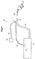
- a fuel system 50 for a motor vehicle includes a fuel tank 51, a filler pipe 53 connecting the fuel tank 51 with a filler opening 52, a fuel vapor passage 54 for expelling fuel vapor from the fuel tank 51 to the outside and a fuel vapor canister 55 provided in the fuel vapor passage 54 for absorbing fuel vapor.
- the fuel absorbed by the canister 55 is expelled therefrom by intake negative pressure of an engine intake system not shown in the drawings, and introduced into the combustion chambers of the engine via the intake system.
- An end of the fuel vapor passage 54 opens out in an upper part of the fuel tank 51, and this open end of the fuel vapor passage 54 is provided with a float valve 57.
- the float valve 57 moves vertically in dependence on the liquid level in the fuel tank 51, and closes the fuel vapor passage 54 when the liquid level exceeds a prescribed value. Therefore, when the liquid level of the fuel in the fuel tank 51 rises by refueling, the fuel vapor passage 54 is closed by the float valve 57, and the fuel liquid is prevented from flowing into the fuel vapor passage 54.
- the liquid level of the fuel in the filler pipe 53 rises, and comes into contact with the filler nozzle 58 (filler gun) of the fuel dispenser of the filling station so that the fuel dispenser detects the full condition of the fuel tank 51, and stops the supply of fuel from the filler nozzle 58.
- an inner tube 61 defining the filler opening 52 is provided in the outer end of the filler pipe 53.
- the outer end 61A of the inner tube 61 is given with a greater outer diameter and inner diameter than the inner end 61B of the inner tube 61 such that the outer peripheral surface of the outer end 61 A of the inner tube 61 is in contact with the inner peripheral surface of the filler pipe 53.
- the inner tube 61 is tapered in the part thereof between the inner end 61 B and the outer end 61A from the outer end side to the inner end side.
- a flap valve 63 is pivotally attached to the inner end of the inner tube 61 for selectively closing the inner end of the inner tube 61.
- the flap valve 63 is urged in the closing direction by a spring not shown in the drawing.
- An upper part of the filler pipe 53 more inward than the flap valve 63 (on the side of the fuel tank 51) is formed with a vertically passed mounting hole 65.
- the surrounding part of the mounting hole 65 projects outward (upward) of the filler pipe 53 to define a boss 66.
- the gas liquid separation device 1 is mounted on this mounting hole 65.
- the end surface of the peripheral wall 18 of the flange 17 of the gas liquid separation device 1 abuts the opposing end surface of the boss 66, and is welded thereto by vibration welding.
- the lower end of the main body 5 of the gas liquid separation device 1 and the flap 6 project into the filler pipe 53.
- the gas liquid separation device 1 is positioned on the filler pipe 53 in such a manner that the flap 6 in the open position faces the outer end of the filler pipe 53 and opposes the flap valve 63.
- the inlet tube 15 of the gas liquid separation device 1 is connected to a fuel tank 51 side part of the fuel vapor passage 54, and the outlet tube 16 is connected to a canister 55 side part of the fuel vapor passage 54.
- the fuel liquid flows downward in the first passage 12 under the gravitational force, and drops into the filler pipe 53.
- the fuel liquid that has dropped into the filler pipe 53 then flows into the fuel tank 51, and is thereby recovered.
- the fuel in the fuel vapor passage 54 is separated into gas and liquid.
- the flap valve device 2 of the gas liquid separation device 1 functions as an outlet for releasing the separated liquid to the outside.
- the communication between the first passage 12 and the second passage 13 is maintained at all times.
- the through hole 14 communicates the first passage 12 and the second passage 13 of the main body 5 with the interior of the filler pipe 53.
- a part of the fuel vapor that flows from the fuel vapor passage 54 to the first passage 12 and the second passage 13 passes into the filler pipe 53 via the through hole 14, and is returned to the fuel tank 51 once again.
- the flap valve device 2 and the gas liquid separation device 1 fitted with the flap valve device 2 are discussed in the following.
- the main body 5, the flap 6, the connecting member 27, the torsion coil spring 7 and the support member 33 can be assembled by the engagement features provided in these components, and the need for crimping and other work requiring tools is eliminated.
- the extension 27B is retained by using the support member 33 engaged by the outer part 6B of the flap 6, the extension 27B can be engaged by the flap 6 simply by positioning the extension 27B to a prescribed position on the flap 6 and engaging the support member 33 with the flap 6 so that the work required for attaching the extension 27B to the flap 6 can be facilitated.
- the first engagement portion 37 is formed as a groove defined by the third side wall 30C and the first projection 36, but may also be defined solely by the third side wall 30C by omitting the first projection 36.
- the first engagement portion 37 is not necessarily required to prevent the lateral movement of the connecting member 27 in the lateral direction, and it suffices if the first engagement portion 37 is at least able to restrict the hinge shaft 27A from coming out of the associated bearings.
Landscapes
- Engineering & Computer Science (AREA)
- General Engineering & Computer Science (AREA)
- Mechanical Engineering (AREA)
- Chemical & Material Sciences (AREA)
- Combustion & Propulsion (AREA)
- Life Sciences & Earth Sciences (AREA)
- Sustainable Development (AREA)
- Sustainable Energy (AREA)
- Transportation (AREA)
- Cooling, Air Intake And Gas Exhaust, And Fuel Tank Arrangements In Propulsion Units (AREA)
- Supplying Secondary Fuel Or The Like To Fuel, Air Or Fuel-Air Mixtures (AREA)
Abstract
Description
- The present invention relates to a flap valve device and a gas liquid separation device provided with a flap valve device, and in particular to a gas liquid separation device for removing liquid from fuel vapor that flows from a fuel tank of a motor vehicle into a fuel vapor canister.
- A fuel tank of a motor vehicle is typically provided with a fuel vapor passage for expelling fuel vapor from the fuel tank and a fuel vapor canister provided in the fuel vapor passage for absorbing the fuel vapor. The fuel absorbed by the canister is drawn from the canister by the intake negative pressure of the intake system, and flows into the combustion chambers via the intake system. In this manner, the fuel vapor is prevented from being released to the atmosphere, and an excessive rise in the internal pressure of the fuel tank can be avoided.
- In such a fuel tank, it is known to open out an end of the fuel vapor passage in an upper part of the fuel tank, and selectively close the open end with a float valve. The float valve moves up and down in dependence on the liquid level of the fuel tank so that the fuel vapor passage is closed when the liquid level rises beyond a prescribed value to prevent the fuel liquid from flowing into the fuel vapor passage. However, when a rapid rise in the liquid or bubbling of the fuel should occur, the fuel liquid could flow into the fuel vapor passage. To remove the fuel liquid that happens to flow into the fuel vapor passage, and prevent the fuel liquid from reaching the fuel vapor canister, it has been proposed to provide a gas liquid separation device in an intermediate point of the fuel passage. See Patent Document 1, for instance.
- In the gas liquid separation device disclosed in Patent Document 1, the fuel liquid separated from the fuel vapor is expelled to the filler pipe that connects the filler opening with the fuel tank. The gas liquid separation device includes a main pipe that extends vertically and has a lower end extending into the filler pipe. The main pipe is closed at the upper end and opens out at the lower end. The interior of the main pipe is separated into a first passage and a second passage by a partition wall extending along the axial line of the main pipe. The upper end of the first passage is connected to the fuel tank side end of the fuel vapor passage, and the upper end of the second passage is connected to the canister side of the fuel vapor passage. The gas liquid separation device includes a normally open type flap valve device which is pivotally attached to the interior of the filler pipe to selectively close the lower end of the main pipe. The flap of the flap valve device is normally in the open position, and can be pushed into the closed position to close the open end of the main pipe by the filler nozzle inserted into the filler pipe during refueling. The flap is configured such that a gap is created between the flap and the partition wall when the flap closes the open end of the main pipe.
- In this gas liquid separation device, the fuel vapor that flows through the fuel vapor passage is passed downward through the first passage, and upward through the second passage via the interior of the filler pipe before reaching the canister. The fuel liquid that may flow in the fuel vapor passage passes from the first passage to the filler pipe under the gravitational force, and does not reach the canister. During refueling, the open end of the main pipe is closed by the filler nozzle pushing the flap into the closed position so that the fuel liquid flowing through the filler pipe does not flow into the main pipe. When the open end of the main pipe is closed, the fuel vapor can pass through the gap between the partition wall and the flap, and flows into the canister via the second passage. On the other hand, the fuel liquid is trapped in the lower end of the main pipe or on top of the flap. When the filler nozzle is pulled out of the filler opening, and the flap opens as a result, the fuel liquid that may have collected on the flap flows into the filler pipe.
- Patent Document 1:
DE10 2008 061 264A - In such a normally open type flap valve device, a hinge bearing is formed on each of a main body of the device and a flap, and a hinge shaft made of metallic material is passed into the hinge bearings of the main body and the flap. The two ends of the hinge shaft are then crimped so as to keep the hinge shaft in position. In this case, a special tool is required for crimping the two ends of the hinge shaft, and the crimping work is required to be performed in a precise manner so that each crimped part of the hinge shaft has a proper length and width. Therefore, the efficiency of the assembly work is poor. Also, as the hinge shaft has to have a sufficient length for the crimping work to be performed in the two ends thereof, the two ends protrude from the respective ends of the hinge, and this impairs the external appearance. Furthermore, owing to the increased length of the hinge axis for the crimping purpose, the hole formed in the filler pipe for inserting the gas liquid separation device into the filler pipe has to be increased in size for passing the hinge shaft through the hole. Also, a torsion coil spring needs to be interposed between the main body and the flap to urge the flap to the normally open position. The torsion coil spring is typically placed on the outer side of the main body and the flap so that the two ends of the torsion coil spring are required to be engaged by features provided on the outer side of the main body and the flap, respectively. The engagement structure for engaging the two ends of the torsion coil spring on the outer side of the main body and the flap tends to be highly complicated as there is a need to engage the two ends in a stable manner, and this additionally impairs the efficiency of the assembly work.
- In view of such problems of the prior art, a primary object of the present invention is to provide a flap valve device and a gas liquid separation device provided with a flap valve wherein the flap valve device is highly compact, and is easy to assemble.
- To achieve such an object, the present invention provides a normally open flap valve device (2) comprising a main body (5) having an opening (4), a flap (6) for selectively closing the opening and a torsion coil spring (7) provided between the main body and the flap for biasing the flap in an opening direction, the flap valve device further comprising: a main body side bearing (21) provided on the main body; a flap side bearing (25) provided on the flap; a connecting member (27) including a hinge shaft (27A) passed through the main body side bearing, the flap side bearing and a coil portion (7A) of the torsion coil spring so as to serve as a pivot shaft for the flap, and an extension (27B) extending from an end of the hinge shaft along an outer part (6B) of the flap; and a spring engagement portion (43) provided on the main body for engaging an end of the torsion coil spring; another end of the torsion coil spring being engaged by the extension, the extension being engaged on the outer part of the flap.
- According to this arrangement, the main body, the flap, the connecting member, the torsion coil spring and the support member can be assembled by the engagement features provided in these components, and the need for crimping and other work requiring tools is eliminated. Therefore, the assemble work is facilitated. Because the extension of the connecting member is retained by using the support member engaged by the inner part of the flap, the extension can be engaged by the flap simply by positioning the extension to a prescribed position on the flap and engaging the support member with the flap so that the work required for securing the extension to the flap can be facilitated.
- In this invention, the flap valve device may further comprise a support member (33) attached to the outer part of the flap for receiving a force for rotating the flap in a closing direction, the support member engaging the extension on the outer part of the flap.
- According to this arrangement, because the extension is engaged by using the support member which is attached to the outer part of the flap, the extension can be secured to the flap simply by positioning the extension on a prescribed position on the flap and engaging the support member onto the flap.
- In this invention, the flap valve device may further comprise a first engagement portion (37) provided on the outer part of the flap for engaging the extension in such a manner that the extension is prevented from moving in an axial direction of the hinge shaft relative to the flap, and is allowed to rotate around the hinge shaft relative to the flap, wherein the support member when attached to the flap engages the extension against a rotational motion of the extension around the hinge shaft, and the extension engages the other end of the torsion coil spring against a rotational motion of the other end of the torsion coil spring around the hinge shaft.
- According to this arrangement, by engaging the extension with the first engagement portion, the connecting member is prevented from moving in the axial direction of the hinge shaft so that the hinge shaft is prevented from coming off the main body side bearing and the flap side bearing. As the extension is engaged by the support member so as to be fixed relative to the flap with respect to the rotation around the hinge shaft, the extension is prevented from being detached from the first engagement portion. Before the support member is engaged by the flap, the extension can be easily positioned onto the first engagement portion by rotating the extension around the hinge shaft so that the positioning of the extension onto the first engagement portion is facilitated.
- In this invention, a through hole (31) may be formed in the outer part of the flap, and the support member may include a front end (33A) passed through the through hole and projecting out of the through hole, and an engagement claw (33F) configured to be engaged by a peripheral edge of the through hole.
- According to this arrangement, the mounting of the support member onto the flap and the engagement of the extension with the support member can be accomplished simply by inserting the support member into the through hole.
- In this invention, the outer part of the flap is provided with a second engagement portion (41) for engaging the other end of the torsion coil spring to restrict a movement of the other end of the torsion coil spring along an axial line of the hinge shaft relative to the flap, and to permit a rotation of the other end of the torsion coil spring around the hinge shaft relative to the flap.
- According to this arrangement, the position of the other end of the torsion coil spring is determined with respect to the axial direction of the hinge shaft by engaging the other end of the torsion coil spring with the second engagement portion so that the other end of the torsion coil spring can be engaged in a stable manner. Because the rotation of the other end of the torsion coil spring around the hinge shaft relative to the flap is permitted, the position of the other end of the torsion coil spring onto the second engagement portion is facilitated.
- In this invention, the flap may be provided with a seal member (24) for sealing an interface between the flap and the main body when the flap is in a closed position.
- According to this arrangement, when the flap is in the closed position, the seal member ensures a favorable seal between the flap and the main body so that the opening can be closed in a reliable manner.
- The present invention further provides a gas liquid separation device provided with the flap valve device as defined above, wherein the flap valve device serves as an outlet for separated liquid.
- According to this arrangement, the gas liquid separation device can be made simple in structure and easy to assemble.
- In this invention, the main body may comprise a pipe extending vertically with a closed upper end and a lower end defining the opening, an interior of the main body being separated by a partition wall (11) into a first passage (12) and a second passage (13) that extend vertically, an upper end of the first passage defining an inlet (15) for receiving liquid, an upper end of the second passage defining an outlet (16) for expelling liquid; wherein the flap is provided on a lower end of the main body to selectively close the opening; and wherein the lower end of the main body projects into a filler pipe connecting a fuel tank (51) of a vehicle with a filler opening (52), and the inlet is connected to a fuel tank side of a fuel vapor passage connecting the fuel tank with the canister (55) while the outlet is connected to a canister side of the fuel vapor passage (54).
- According to this arrangement, the gas liquid separation device configured to be provided in a passage for conducting fuel vapor from the fuel tank to the fuel vapor canister can be constructed as a highly simple unit.
- According to such arrangements, in a flap valve device and a gas liquid separation device provided with a flap valve device, the flap valve device can be made highly compact, and easy to assemble.
-
-
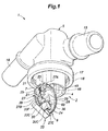
Figure 1 is a perspective view of a gas liquid separation device provided with a flap valve device embodying the present invention; -
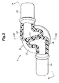
Figure 2 is a cross sectional view of the gas liquid separation device; -
Figure 3 is a sectional view taken along line III-III ofFigure 2 ; -
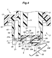
Figure 4 is a sectional view taken along line IV-IV ofFigure 2 when the flap is closed; -
Figure 5 is a side view of the flap valve device; -
Figure 6 is a diagram showing the fuel system of a motor vehicle incorporated with the gas fuel separation device; -
Figure 7 is a section view of the fuel system for demonstrating the mode of operation of the gas fuel separation device; and -
Figure 8 is a section view of the fuel system for demonstrating the mode of operation of the gas fuel separation device. - The flap valve device and the gas liquid separation device provided with the flap valve device are described in the following with reference to the appended drawings. The gas liquid separation device of the illustrated embodiment is provided in a fuel vapor passage connecting the fuel tank with the fuel vapor canister in a motor vehicle, and is configured to return the separated fuel liquid into the filler pipe.
- As shown in
Figures 1 to 3 , the gas liquid separation device 1 is provided with theflap valve device 2 which includes amain body 5 having anopening 4, aflap 6 configured to selectively open theopening 4 and atorsion coil spring 7 provided between themain body 5 and theflap 6 to urge theflap 6 in the closing direction. - The
main body 5 is tubular in shape, and extends vertically with a closed upper end and an open lower end (the opening 4). Themain body 5 is internally provided with apartition wall 11 extending in the axial direction. Thepartition wall 11 diametrically separates the interior of themain body 5 into afirst passage 12 and asecond passage 13 both extending in the vertical direction. The lower end of thepartition wall 11 is positioned higher than the lower end of themain body 5 so that the two lower ends of thefirst passage 12 and thesecond passage 13 communicate with each other. A throughhole 14 is passed through a part of themain body 5 slightly spaced from the lower end thereof so as to communicate the interior and the exterior of themain body 5 with each other. - An
inlet tube 15 and anoutlet tube 16 project from opposite sides of the upper end of themain body 5. The base ends of theinlet tube 15 and theoutlet tube 16 are 180 degrees apart along the outer periphery of themain body 5. Theinlet tube 15 and theoutlet tube 16 extend tangentially and in opposite directions from the outer peripheral parts of themain body 5. The interior of theinlet tube 15 communicates with the upper end of thefirst passage 12, and the interior of theoutlet tube 16 communicates with the upper end of thesecond passage 13. Theinlet tube 15 and theoutlet tube 16 are provided with a downward slant toward the respective free ends thereof which define open ends. - An intermediate portion of the
main body 5 with respect to the lengthwise direction is formed with acircular flange 17 extending radially outward. The outer periphery of theflange 17 is provided with aperipheral wall 18 extending vertically downward. Theperipheral wall 18 extends along the outer periphery of theflange 17 in an annular fashion. - The
main body 5, theinlet tube 15, theoutlet tube 16 and theflange 17 are integrally molded by plastic material. Themain body 5, theinlet tube 15, theoutlet tube 16 and theflange 17 are two-color injection molded in such a manner that the outer side and the inner side of themain body 5, theinlet tube 15, theoutlet tube 16 and theflange 17 are formed as an outer layer and an inner layer, respectively. The outer layer is made of stiffer material than the inner layer, such as HDPE. The inner layer functions as a barrier layer made of material having a low permeability for gasoline, such as plastic material consisting of a mixture of PA6 (nylon 6) and HDPE. The downward facing end surface of theperipheral wall 18 is formed by the outer layer. - As shown
Figures 1 to 5 , an outer side part of the lower end of themain body 5 is provided with a pair of mainbody side bearings 21 which are spaced apart from each other along the tangential direction of themain body 5, and define respective bearing holes extending coaxially in the tangential direction. Each bearing hole consists of a through hole. In the following description, the axial line of the bearing holes is assumed as extending in the lateral direction. - As shown in
Figures 1 ,4 and5 , the lower end of themain body 5 is pivotally fitted with aflap 6 for selectively closing theopening 4. Theflap 6 consists of a disk-shaped lid, and is made of plastic material such as POM. As shown inFigure 4 , theflap 6 includes aninner part 6A and anouter part 6B positioned one over the other, and theinner part 6A has a smaller diameter than theouter part 6B so as to define a stepped outer periphery. The outer diameter of theouter part 6B is greater than the inner diameter of theopening 4 of themain body 5, and the outer diameter of theinner part 6A is smaller than the inner diameter of theopening 4 of themain body 5 so that theinner part 6A of theflap 6 projects into theopening 4 while the outer part of theflap 6 remains on the outer side of theopening 4. Anannular engagement groove 23 is defined along the periphery of theflap 6 between theinner part 6A and theouter part 6B. Anannular seal member 24 is fitted into theannular engagement groove 23. Thereby, when theflap 6 is in the closed position, theouter part 6B abuts the periphery of theopening 4 via theseal member 24. - As shown in
Figures 1 and5 , a pair offlap side bearings 25 are provided on an outer peripheral part of theouter part 6B of theflap 6. Theflap side bearings 25 are spaced apart from each other along the tangential direction of theflap 6, and define respective bearing holes extending coaxially in the tangential direction. Each bearing hole consists of a through hole. - The
flap side bearings 25 of theflap 6 are connected to the mainbody side bearings 21 of themain body 5 via a connectingmember 27 so that theflap 6 is pivotally attached to themain body 5. The connectingmember 27 includes ahinge shaft 27A extending in the axial direction, and anextension 27B extending from an end of thehinge shaft 27A. In the illustrated embodiment, the connectingmember 27 is formed by bending a metallic rod into a prescribed shape. Thehinge shaft 27A extends linearly. Theextension 27B includes abase end 27C bent from an end of thehinge shaft 27A in a perpendicular direction, anintermediate portion 27D bent from the other end of thebase end 27C in parallel with thehinge shaft 27A and afree end 27E extending from the other end of theintermediate portion 27D in a perpendicular direction. - The
flap 6 is positioned relative to themain body 5 such that the two mainbody side bearings 21 are interposed between the twoflap side bearings 25. The bearings holes of the flap side bearing 25 and the mainbody side bearings 21 are coaxially aligned with one another, and thehinge shaft 27A of the connectingmember 27 is passed into one of theflap side bearings 25, one of the mainbody side bearings 21, the other main body side bearing 21 and the other flap side bearing 25, in that order, so that theflap 6 is pivotally attached to themain body 5 via the connectingmember 27. Under this condition, the axial line of the bearings holes of the flap side bearing 25 and the mainbody side bearings 21 and the axial line of thehinge shaft 27A extend laterally. - The connecting
member 27 is thus able to pivot around thehinge shaft 27A relative to themain body 5 and theflap 6 when the connectingmember 27 is passed through theflap side bearings 25 and the mainbody side bearings 21. Theextension 27B can be positioned onto theouter part 6B of theflap 6 by pivoting the connectingmember 27 around thehinge shaft 27A. - As shown in
Figures 1 ,4 and5 , theouter part 6B of theflap 6 is centrally formed with arecess 29 having a semi-circular cross section. Asupport base 30 having a rectangular shape projects from a part of theouter part 6B on the side opposite from theflap side bearings 25 with respect to therecess 29. Afirst side wall 30A provided on a side of thesupport base 30 adjacent to therecess 29 opposes theflap side bearings 25 and extends substantially in parallel with thehinge shaft 27A. The side of thesupport base 30 opposite to thefirst side wall 30A is formed with asecond side wall 30B. Aslot 31 is passed through thefirst side wall 30A and thesecond side wall 30B in a direction perpendicular to thehinge shaft 27A. Theslot 31 is provided with a rectangular, laterally elongated cross section, and is configured to accept asupport member 33 which will be described hereinafter. The projecting end surface of thesupport base 30 is formed with aslit 34 communicating with theslot 31. Theslit 34 extends in a direction perpendicular to thehinge shaft 27A, and is passed through thefirst side wall 30A at an end thereof. - The two lateral sides of the
support base 30 is formed with athird side wall 30C and afourth side wall 30D, respectively, in a perpendicular relationship to thefirst side wall 30A and thesecond side wall 30B. Thethird side wall 30C is located on the side corresponding to the free end of thehinge shaft 27A (on the right hand side inFigure 5 ). Afirst projection 36 is formed on theouter part 6B of theflap 6 laterally spaced from thethird side wall 30C by a prescribed distance, and is elongated in a direction perpendicular to thehinge shaft 27A. Thethird side wall 30C and thefirst projection 36 jointly define afirst engagement portion 37 formed as a groove extending in a direction perpendicular to thehinge shaft 27A. - The
outer part 6B of theflap 6 is further provided with asecond projection 38 and athird projection 39. Thesecond projection 38 is L-shaped, and has a first end extending in parallel with thehinge shaft 27A and a second end extending into therecess 29 toward thesupport base 30 on a part of theouter part 6B of theflap 6 located between therecess 29 and theflap side bearings 25. The end of thesecond projection 38 extending toward thesupport base 30 is spaced from thefirst side wall 30A by a prescribed distance. Thethird projection 39 is laterally spaced from the right end of thesecond projection 38 by a prescribed distance. Thereby, thesecond projection 38 and thethird projection 39 jointly define asecond engagement portion 41 formed as a groove extending in a direction perpendicular to thehinge shaft 27A. The end part of thesecond projection 38 opposing thethird projection 39 defines a sloping surface that decreases in height toward thethird projection 39. - The connecting
member 27 is arranged such that theextension 27B extends along theouter part 6B of theflap 6, and theintermediate portion 27D extends between thesecond projection 38 and thesupport base 30 along thefirst side wall 30A. Thefree end 27E is positioned in thefirst engagement portion 37. Owing to the positioning of thefree end 27E in thefirst engagement portion 37, thefree end 27E is prevented from moving laterally by thethird side wall 30C and thefirst projection 36. Owing to the engagement of thefree end 27E by thefirst engagement portion 37, the connectingmember 27 is prevented from moving laterally or along the axial direction of thehinge shaft 27A, and thehinge shaft 27A is kept received in the mainbody side bearings 21 and theflap side bearings 25. - The
support member 33 is configured to receive the external force for rotating theflap 6. Thesupport member 33 is formed by bending a sheet spring consisting of a metallic strip. Thesupport member 33 is provided with aninsertion end 33A inserted in theslot 31 at a lengthwise end thereof, abent portion 33B bent into a hairpin shape in a lengthwise intermediate part thereof and apressure receiving portion 33C for receiving an external force at the other lengthwise end thereof. - The
insertion end 33A is passed into theslot 31 from the side of thesecond side wall 30B to thefirst side wall 30A. Theinsertion end 33A is provided with ashoulder portion 33D abutting thesecond side wall 30B. Theshoulder portion 33D is formed by bending thesupport member 33 in a crank shape. The insertion depth of theinsertion end 33A into theslot 31 is determined by the abutment of theshoulder portion 33D onto thesecond side wall 30B. - The
insertion end 33A is formed with acurved portion 33E in the free end thereof, and thecurved portion 33E extends out of theslot 31 from the open end of theslot 31 on the side of thefirst side wall 30A. Thecurved portion 33E can pass through theslot 31 by deflecting, and regain the original shape after passing through theslot 31. Thereby, theinsertion end 33A is normally retained in theslot 31. Thecurved portion 33E is formed with anelastic claw 33F by virtue of a C-shaped cut made therein. The projecting end of theelastic claw 33F faces thefirst side wall 30A so that theinsertion end 33A can be even more securely retained in theslot 31 by the abutting of the projecting end of theelastic claw 33F onto thefirst side wall 30A. - The end (main part) of the
insertion end 33A opposite to the free end extends outward in the radial direction of theflap 6. Thepressure receiving portion 33C is connected to theinsertion end 33A via thebent portion 33B, and folded back radially from an radially outer part to a radially inner part of theflap 6. Thepressure receiving portion 33C extends with a certain incline such that the distance to theouter part 6B of theflap 6 increases toward the center of theflap 6. - The
support member 33 is mounted on theflap 6 and theinsertion end 33A projects from thefirst side wall 30A in such a manner that theinsertion end 33A extends above theintermediate portion 27D of the connectingmember 27. Owing to the retention of theintermediate portion 27D by theinsertion end 33A, the rotation of the connectingmember 27 around thehinge shaft 27A is restricted, and thefree end 27E is kept engaged by thefirst engagement portion 37. In other words, by mounting thesupport member 33 on theflap 6, the connectingmember 27 is prevented from coming off theflap 6 so that theflap 6 is supported by themain body 5 in a stable manner. - The
torsion coil spring 7 includes acoil portion 7A and a first andsecond end coil portion 7A. Thecoil portion 7A is positioned between the two mainbody side bearings 21, and internally receives thehinge shaft 27A so that thecoil portion 7A is rotatably supported by thehinge shaft 27A. The part of themain body 5 located between the two mainbody side bearings 21 is provided with aspring engagement portion 43 for engaging thefirst end 7B of thetorsion coil spring 7. Thespring engagement portion 43 consists of a hole elongated in the lengthwise direction, and has an open lower end. Thefirst end 7B of thetorsion coil spring 7 is engaged by thespring engagement portion 43 by being loosely received in thespring engagement portion 43, and contacting the peripheral edge of the hole (spring engagement portion 43). - The
second end 7C of the torsion coil spring is passed between theintermediate portion 27D of the connectingmember 27 and theflap 6, and extends into theslot 31. Thetorsion coil spring 7 urges theflap 6 in the opening direction relative to themain body 5, and thesecond end 7C contacts the side of theintermediate portion 27D facing theflap 6, and is engaged thereby. - A
stopper 45 extends downward from each main body side bearing 21. Theouter part 6B of theflap 6 is formed withseats 46 for therespective stoppers 45 to abut on. The open position (maximum open position) of theflap 6 relative to themain body 5 is determined by the abutting of thestoppers 45 onto therespective seats 46. - The gas liquid separation device 1 described above can be assembled as discussed in the following. First of all, the
flap 6 is positioned relative to themain body 5 such that the mainbody side bearings 21 are positioned between theflap side bearings 25 in a coaxial arrangement. Thetorsion coil spring 7 is then positioned on themain body 5 such that thefirst end 7B of thetorsion coil spring 7 is inserted into and engaged by thespring engagement portion 43, and thecoil portion 7A is positioned between the mainbody side bearings 21 in a coaxial arrangement with the axial line of thebearings hinge shaft 27A of the connectingmember 27 is passed into theflap side bearings 25, the mainbody side bearings 21 and thecoil portion 7A of thetorsion coil spring 7 arranged in a mutually coaxial relationship. Thereby, themain body 5, theflap 6 and thetorsion coil spring 7 are provisionally assembled via thehinge shaft 27A. - The
second end 7C of thetorsion coil spring 7 is positioned between theintermediate portion 27D of the connectingmember 27 and theflap 6. This positioning step for thesecond end 7C is performed simultaneously as or before completing the insertion of thehinge shaft 27A. Because thecoil portion 7A of thetorsion coil spring 7 is readily deformable, the positioning of thesecond end 7C can be performed easily even after thehinge shaft 27A has been inserted. - The connecting
member 27 is rotated around thehinge shaft 27A against the biasing force of thetorsion coil spring 7 until the connectingmember 27 comes into contact with theouter part 6B of theflap 6 with the result that thefree end 27E of the connectingmember 27 is positioned in thefirst engagement portion 37 and theintermediate portion 27D is positioned adjacent to thefirst side wall 30A. At this time, thesecond end 7C of thetorsion coil spring 7 that may be moved with the connectingmember 27 is passed into theslot 31 via theslit 34, and positioned in thesecond engagement portion 41. As thesecond end 7C advances into thesecond engagement portion 41, thesecond end 7C is guided by the sloping surface of thesecond projection 38, and is positioned in the prescribed location of thesecond engagement portion 41. The lateral position of thetorsion coil spring 7 is determined by thesecond end 7C being positioned in thesecond engagement portion 41. - The
insertion end 33A of thesupport member 33 is then inserted into theslot 31. As theinsertion end 33A is forced into theslot 31, thecurved portion 33E and theelastic claw 33F deflect by being pressed by the peripheral edge of theslot 31 so that theinsertion end 33A gets through theslot 31. Once the free end of theinsertion end 33A projects out of theslot 31, thecurved portion 33E regains the original shape so that theinsertion end 33A is prevented from coming off theslot 31. Also, because theelastic claw 33F also regains the original shape, the projecting end of theelastic claw 33F abuts thefirst side wall 30A so that thesupport member 33 is prevented from coming off theslot 31. - Because the
insertion end 33A projects from theslot 31, theintermediate portion 27D of the connectingmember 27 is engaged by theinsertion end 33A so that the rotation of the connectingmember 27 around thehinge shaft 27A is prevented. Because the rotation of the connectingmember 27 around thehinge shaft 27A is prevented, thefree end 27E is kept engaged by thefirst engagement portion 37, and the lateral movement of the connectingmember 27 is prevented. Therefore, thehinge shaft 27A is prevented from moving out of the mainbody side bearings 21, theflap side bearings 25 and thecoil portion 7A of thetorsion coil spring 7. Thus, the assembly work of theflap valve device 2 can be carried out in a highly simple manner without requiring tools. - Referring to
Figures 6 to 8 , the arrangement for installing the gas liquid separation device 1 in a motor vehicle is described in the following. As shown inFigure 6 , afuel system 50 for a motor vehicle includes afuel tank 51, afiller pipe 53 connecting thefuel tank 51 with afiller opening 52, afuel vapor passage 54 for expelling fuel vapor from thefuel tank 51 to the outside and afuel vapor canister 55 provided in thefuel vapor passage 54 for absorbing fuel vapor. The fuel absorbed by thecanister 55 is expelled therefrom by intake negative pressure of an engine intake system not shown in the drawings, and introduced into the combustion chambers of the engine via the intake system. - An end of the
fuel vapor passage 54 opens out in an upper part of thefuel tank 51, and this open end of thefuel vapor passage 54 is provided with afloat valve 57. Thefloat valve 57 moves vertically in dependence on the liquid level in thefuel tank 51, and closes thefuel vapor passage 54 when the liquid level exceeds a prescribed value. Therefore, when the liquid level of the fuel in thefuel tank 51 rises by refueling, thefuel vapor passage 54 is closed by thefloat valve 57, and the fuel liquid is prevented from flowing into thefuel vapor passage 54. If refueling is continued after thefloat valve 57 is closed, the liquid level of the fuel in thefiller pipe 53 rises, and comes into contact with the filler nozzle 58 (filler gun) of the fuel dispenser of the filling station so that the fuel dispenser detects the full condition of thefuel tank 51, and stops the supply of fuel from thefiller nozzle 58. - As shown in
Figure 7 , aninner tube 61 defining thefiller opening 52 is provided in the outer end of thefiller pipe 53. Theouter end 61A of theinner tube 61 is given with a greater outer diameter and inner diameter than theinner end 61B of theinner tube 61 such that the outer peripheral surface of theouter end 61 A of theinner tube 61 is in contact with the inner peripheral surface of thefiller pipe 53. Theinner tube 61 is tapered in the part thereof between theinner end 61 B and theouter end 61A from the outer end side to the inner end side. Aflap valve 63 is pivotally attached to the inner end of theinner tube 61 for selectively closing the inner end of theinner tube 61. Theflap valve 63 is urged in the closing direction by a spring not shown in the drawing. When thefiller nozzle 58 is inserted in thefiller opening 52, and theflap valve 63 is pushed by the tip of thefiller nozzle 58, theflap valve 63 opens. - An upper part of the
filler pipe 53 more inward than the flap valve 63 (on the side of the fuel tank 51) is formed with a vertically passed mountinghole 65. The surrounding part of the mountinghole 65 projects outward (upward) of thefiller pipe 53 to define aboss 66. The gas liquid separation device 1 is mounted on this mountinghole 65. The end surface of theperipheral wall 18 of theflange 17 of the gas liquid separation device 1 abuts the opposing end surface of theboss 66, and is welded thereto by vibration welding. The lower end of themain body 5 of the gas liquid separation device 1 and theflap 6 project into thefiller pipe 53. The gas liquid separation device 1 is positioned on thefiller pipe 53 in such a manner that theflap 6 in the open position faces the outer end of thefiller pipe 53 and opposes theflap valve 63. - The
inlet tube 15 of the gas liquid separation device 1 is connected to afuel tank 51 side part of thefuel vapor passage 54, and theoutlet tube 16 is connected to acanister 55 side part of thefuel vapor passage 54. - In this gas liquid separation device 1 constructed as described above, when the liquid level of the
fuel tank 51 has suddenly risen or when bubbling of fuel has occurred in thefuel tank 51, fuel liquid may advance into thefuel vapor passage 54 via thefloat valve 57, but the fuel liquid that has advanced into thefuel vapor passage 54 can be expelled to thefiller pipe 53. The fuel vapor and the fuel liquid that flow in thefuel vapor passage 54 eventually flow into the gas liquid separation device 1. When theflap 6 is open as shown inFigure 7 , the fuel vapor flows downward in thefirst passage 12, and then in thesecond passage 13 either directly from thefirst passage 12 or via the interior of thefiller pipe 53. The fuel vapor flows upward in thesecond passage 13, and is introduced into thecanister 55 via theoutlet tube 16. Meanwhile, the fuel liquid flows downward in thefirst passage 12 under the gravitational force, and drops into thefiller pipe 53. The fuel liquid that has dropped into thefiller pipe 53 then flows into thefuel tank 51, and is thereby recovered. In this manner, the fuel in thefuel vapor passage 54 is separated into gas and liquid. Theflap valve device 2 of the gas liquid separation device 1 functions as an outlet for releasing the separated liquid to the outside. - As shown in
Figure 8 , when thefiller nozzle 58 is inserted into thefiller opening 52, and theflap valve 63 is thereby forced open, theflap 6 is pushed by theflap valve 63 at thesupport member 33, and forced to the closed position against the biasing force of thetorsion coil spring 7. As thesupport member 33 is elastically deformable, once theflap valve 63 is opened beyond a certain open position, theflap 6 is maintained in the closed position. In other words, theflap valve 63 can open even further than the open position that is required to force theflap 6 to the closed position thereof. Owing to the elastic deformation of thesupport member 33, theflap 6 is biased in the closed direction, and abuts the lower end of themain body 5 via theseal member 24. Thus, when thefiller nozzle 58 is inserted in thefiller pipe 53, theflap 6 is closed so that the fuel liquid that is supplied from thefiller nozzle 58 into thefiller pipe 53 is prevented from advancing into the gas liquid separation device 1. - When the
flap 6 is in the closed position, a gap is created between theinner part 6A of theflap 6 and the lower end of thepartition wall 11. Therefore, even when theflap 6 is in the closed position, thefirst passage 12 and thesecond passage 13 are communicated with each other at the lower end. The fuel vapor and the fuel liquid that flow in thefuel vapor passage 54 both flow downward in thefirst passage 12. The fuel vapor then flows upward in thesecond passage 13, and flows into thecanister 55 via theoutlet tube 16. Meanwhile, the fuel liquid is unable to flow upward in thesecond passage 13 on account of the gravitational force, and is trapped on top of theinner part 6A of theflap 6. When the trapped fuel liquid increases beyond a certain limit, the fuel liquid passes through the throughhole 14, and is expelled to thefiller pipe 53. Therefore, the communication between thefirst passage 12 and thesecond passage 13 is maintained at all times. When theflap 6 is in the closed position, the throughhole 14 communicates thefirst passage 12 and thesecond passage 13 of themain body 5 with the interior of thefiller pipe 53. As a result, a part of the fuel vapor that flows from thefuel vapor passage 54 to thefirst passage 12 and thesecond passage 13 passes into thefiller pipe 53 via the throughhole 14, and is returned to thefuel tank 51 once again. - When the
filler nozzle 58 is pulled off from thefiller opening 52, and theflap valve 63 rotates to the closed position, theflap 6 rotates to the open position under the biasing force of thetorsion coil spring 7, and the fuel liquid trapped on top of theinner part 6A of theflap 6 is expelled to the interior of thefiller pipe 53. - The advantages of the
flap valve device 2 and the gas liquid separation device 1 fitted with theflap valve device 2 are discussed in the following. In theflap valve device 2 and the gas liquid separation device 1 of the illustrated embodiment, themain body 5, theflap 6, the connectingmember 27, thetorsion coil spring 7 and thesupport member 33 can be assembled by the engagement features provided in these components, and the need for crimping and other work requiring tools is eliminated. Because theextension 27B is retained by using thesupport member 33 engaged by theouter part 6B of theflap 6, theextension 27B can be engaged by theflap 6 simply by positioning theextension 27B to a prescribed position on theflap 6 and engaging thesupport member 33 with theflap 6 so that the work required for attaching theextension 27B to theflap 6 can be facilitated. - When the
support member 33 is yet to be attached to theflap 6, the positioning of theextension 27B onto thefirst engagement portion 37 is facilitated because theextension 27B can be readily moved to thefirst engagement portion 37 simply by rotating theextension 27B around thehinge shaft 27A. - The specific embodiment of the present invention has been described above, but the present invention is not limited by such an embodiment, and can be modified in various ways without departing from the spirit of the present invention. For instance, the
first engagement portion 37 is formed as a groove defined by thethird side wall 30C and thefirst projection 36, but may also be defined solely by thethird side wall 30C by omitting thefirst projection 36. In other words, thefirst engagement portion 37 is not necessarily required to prevent the lateral movement of the connectingmember 27 in the lateral direction, and it suffices if thefirst engagement portion 37 is at least able to restrict thehinge shaft 27A from coming out of the associated bearings.GLOSSARY OF TERMS 1 gas liquid separation device 2 flap valve device 4 open end 5 main body 6A inner part 6B outer part 7 torsion coil spring 7A coil 7B first end 7C second end 11 partition wall 12 first passage 13 second passage 15 inlet tube (inlet) 16 outlet tube (outlet) 21 main body side bearing 23 engagement groove 24 seal member 25 flap side bearing 27 connecting member 27A hinge shaft 27B extension 27C base end 27D intermediate portion 27E free end 30 support base 31 slot (through hole) 33 support member 33A insertion end 33B bent portion 33C pressure receiving portion 33D shoulder portion 33E curved portion 33F elastic claw (engagement claw) 36 first projection 37 first engagement portion 38 second projection 39 third projection 41 second engagement portion 43 spring engagement portion 50 fuel system 51 fuel tank 52 filler opening 53 filler pipe 54 fuel vapor passage 55 canister 57 float valve 68 filler nozzle
Claims (8)
- A normally open flap valve device comprising a main body having an opening, a flap for selectively closing the opening and a torsion coil spring provided between the main body and the flap for biasing the flap in an opening direction, the flap valve device further comprising:a main body side bearing provided on the main body;a flap side bearing provided on the flap;a connecting member including a hinge shaft passed through the main body side bearing, the flap side bearing and a coil portion of the torsion coil spring so as to serve as a pivot shaft for the flap, and an extension extending from an end of the hinge shaft along an outer part of the flap; anda spring engagement portion provided on the main body for engaging an end of the torsion coil spring;another end of the torsion coil spring being engaged by the extension, the extension being engaged on the outer part of the flap.
- The flap valve device according to claim 1, further comprising a support member attached to the outer part of the flap for receiving a force for rotating the flap in a closing direction, the support member engaging the extension on the outer part of the flap.
- The flap valve device according to claim 2, further comprising a first engagement portion provided on the outer part of the flap for engaging the extension in such a manner that the extension is prevented from moving in an axial direction of the hinge shaft relative to the flap, and is allowed to rotate around the hinge shaft relative to the flap,
wherein the support member when attached to the flap engages the extension against a rotational motion of the extension around the hinge shaft, and the extension engages the other end of the torsion coil spring against a rotational motion of the other end of the torsion coil spring around the hinge shaft. - The flap valve device according to claim 2 or 3, wherein a through hole is formed in the outer part of the flap, and the support member includes a front end passed through the through hole and projecting out of the through hole, and an engagement claw configured to be engaged by a peripheral edge of the through hole.
- The flap valve device according to any one of claims 1 to 4, wherein the outer part of the flap is provided with a second engagement portion for engaging the other end of the torsion coil spring to restrict a movement of the other end of the torsion coil spring along an axial line of the hinge shaft relative to the flap, and to permit a rotation of the other end of the torsion coil spring around the hinge shaft relative to the flap.
- The flap valve device according to any one of claims 1 to 5, wherein the flap is provided with a seal member for sealing an interface between the flap and the main body when the flap is in a closed position.
- A gas liquid separation device provided with the flap valve device according to any one of claims 1 to 6, wherein the flap valve device serves as an outlet for separated liquid.
- The gas liquid separation device according to claim 7, wherein the main body comprises a pipe extending vertically with a closed upper end and a lower end defining the opening, an interior of the main body being separated by a partition wall into a first passage and a second passage that extend vertically, an upper end of the first passage defining an inlet for receiving liquid, an upper end of the second passage defining an outlet for expelling liquid;
wherein the flap is provided on a lower end of the main body to selectively close the opening; and
wherein the lower end of the main body projects into a filler pipe connecting a fuel tank of a vehicle with a filler opening, and the inlet is connected to a fuel tank side of a fuel vapor passage connecting the fuel tank with the canister while the outlet is connected to a canister side of the fuel vapor passage.
Applications Claiming Priority (2)
| Application Number | Priority Date | Filing Date | Title |
|---|---|---|---|
| JP2013254672A JP6106073B2 (en) | 2013-12-10 | 2013-12-10 | Flap valve device and gas-liquid separator equipped with flap valve device |
| PCT/JP2014/005991 WO2015087506A1 (en) | 2013-12-10 | 2014-12-01 | Flap valve device and gas-liquid separating device comprising flap valve device |
Publications (3)
| Publication Number | Publication Date |
|---|---|
| EP3081801A1 true EP3081801A1 (en) | 2016-10-19 |
| EP3081801A4 EP3081801A4 (en) | 2017-09-13 |
| EP3081801B1 EP3081801B1 (en) | 2020-03-04 |
Family
ID=53370837
Family Applications (1)
| Application Number | Title | Priority Date | Filing Date |
|---|---|---|---|
| EP14869475.5A Active EP3081801B1 (en) | 2013-12-10 | 2014-12-01 | Flap valve device and gas-liquid separating device comprising flap valve device |
Country Status (8)
| Country | Link |
|---|---|
| US (1) | US9908401B2 (en) |
| EP (1) | EP3081801B1 (en) |
| JP (1) | JP6106073B2 (en) |
| KR (1) | KR101862958B1 (en) |
| CN (1) | CN105814301B (en) |
| ES (1) | ES2778202T3 (en) |
| HU (1) | HUE049429T2 (en) |
| WO (1) | WO2015087506A1 (en) |
Families Citing this family (9)
| Publication number | Priority date | Publication date | Assignee | Title |
|---|---|---|---|---|
| DE102015012656B4 (en) * | 2014-10-22 | 2025-07-17 | Audi Ag | Method for operating a fuel system for a motor vehicle and corresponding fuel system |
| EP3238972B1 (en) * | 2016-04-27 | 2019-12-18 | Magna Steyr Fuel Systems GesmbH | Separation nipple |
| KR102710757B1 (en) * | 2016-08-10 | 2024-09-27 | 삼성전자주식회사 | Method for providing parking location information of a vehicle and electronic device thereof |
| JP6693398B2 (en) * | 2016-12-05 | 2020-05-13 | 豊田合成株式会社 | Fuel tank opening / closing device |
| KR101965400B1 (en) * | 2018-02-12 | 2019-04-03 | 동아대학교 산학협력단 | Check valve with adjustable flow rate |
| CN108775427B (en) * | 2018-07-23 | 2023-12-01 | 南京西普国际工程有限公司 | Micro-motion type gravity flap valve assembly, gravity flap valve and feeding pipe |
| US10843555B2 (en) * | 2018-09-28 | 2020-11-24 | Toyoda Gosei Co., Ltd. | Opening/closing device of fuel tank |
| US11052755B2 (en) | 2019-07-11 | 2021-07-06 | Martinrea International US Inc. | Compound spring for capless fuel door |
| US11852256B2 (en) * | 2020-03-11 | 2023-12-26 | Ockerman Automation Consulting, Inc. | Flush-mount valve |
Family Cites Families (20)
| Publication number | Priority date | Publication date | Assignee | Title |
|---|---|---|---|---|
| US4715509A (en) * | 1985-07-31 | 1987-12-29 | Toyota Jidosha Kabushiki Kaisha | Fuel filler conduit |
| US5027868A (en) * | 1986-12-23 | 1991-07-02 | Gt Development Corporation | Vapor recovery systems |
| US4809865A (en) * | 1987-02-20 | 1989-03-07 | Toyota Jidosha Kabushiki Kaisha | Fuel tank for use in a vehicle |
| US5022433A (en) * | 1988-06-09 | 1991-06-11 | Temtech Fahrzeugtechnik Entwicklungsgellschaft Mbh | Shut-off valve |
| US4917157A (en) * | 1989-02-27 | 1990-04-17 | General Motors Corporation | Vehicle tank vapor vent valve assembly |
| US5195566A (en) * | 1991-05-01 | 1993-03-23 | Mecrom Ott & Holey Ohg | Cap for the filler neck of liquid containers |
| JP3332978B2 (en) * | 1993-03-11 | 2002-10-07 | キーパー株式会社 | Fuel tank filler unit |
| DE19500475C2 (en) * | 1995-01-10 | 2001-09-27 | Schatz Thermo Gastech Gmbh | Shut-off or throttle valve with rotatable valve flap |
| JPH10325373A (en) * | 1997-05-27 | 1998-12-08 | Kubota Corp | Fuel filter |
| AT408970B (en) * | 1997-11-27 | 2002-04-25 | Blau Internat Gesmbh | DEVICE FOR PREVENTING OVERFILLING OF A FUEL TANK |
| US6029719A (en) * | 1998-04-13 | 2000-02-29 | Firma Carl Freudenberg | Fuel tank |
| FR2844486B1 (en) * | 2002-09-13 | 2005-05-13 | Inergy Automotive Systems Res | SEALING AND SECURITY DEVICE FOR FILLING A HOLLOW BODY WITH A LIQUID |
| JP2007331518A (en) * | 2006-06-14 | 2007-12-27 | Asteer Co Ltd | Fuel feed pipe |
| US7694665B2 (en) | 2007-02-05 | 2010-04-13 | Raval A.C.S. Ltd. | Liquid vapor separator |
| JP5319974B2 (en) * | 2008-07-18 | 2013-10-16 | 株式会社アステア | Filling port closing device |
| DE102008061264B4 (en) | 2008-12-10 | 2015-04-02 | Kautex Textron Gmbh & Co. Kg | Fuel tank |
| US8596311B2 (en) * | 2009-11-24 | 2013-12-03 | Eaton Corporation | Valve assembly for a fuel recirculation line |
| DE102009057860B4 (en) * | 2009-12-11 | 2016-09-29 | Kautex Textron Gmbh & Co. Kg | Fuel tank |
| JP5739246B2 (en) | 2011-06-20 | 2015-06-24 | 本田技研工業株式会社 | Fuel tank equipment |
| JP5712881B2 (en) | 2011-09-27 | 2015-05-07 | 豊田合成株式会社 | Fuel tank opening and closing device |
-
2013
- 2013-12-10 JP JP2013254672A patent/JP6106073B2/en active Active
-
2014
- 2014-12-01 ES ES14869475T patent/ES2778202T3/en active Active
- 2014-12-01 US US15/101,542 patent/US9908401B2/en active Active
- 2014-12-01 CN CN201480067001.6A patent/CN105814301B/en active Active
- 2014-12-01 KR KR1020167018314A patent/KR101862958B1/en active Active
- 2014-12-01 HU HUE14869475A patent/HUE049429T2/en unknown
- 2014-12-01 EP EP14869475.5A patent/EP3081801B1/en active Active
- 2014-12-01 WO PCT/JP2014/005991 patent/WO2015087506A1/en not_active Ceased
Also Published As
| Publication number | Publication date |
|---|---|
| HUE049429T2 (en) | 2020-09-28 |
| US20170015192A1 (en) | 2017-01-19 |
| ES2778202T3 (en) | 2020-08-10 |
| KR20160097285A (en) | 2016-08-17 |
| KR101862958B1 (en) | 2018-05-31 |
| EP3081801A4 (en) | 2017-09-13 |
| WO2015087506A1 (en) | 2015-06-18 |
| CN105814301A (en) | 2016-07-27 |
| JP6106073B2 (en) | 2017-03-29 |
| US9908401B2 (en) | 2018-03-06 |
| JP2015113732A (en) | 2015-06-22 |
| EP3081801B1 (en) | 2020-03-04 |
| CN105814301B (en) | 2019-02-12 |
Similar Documents
| Publication | Publication Date | Title |
|---|---|---|
| EP3081801B1 (en) | Flap valve device and gas-liquid separating device comprising flap valve device | |
| US9957152B2 (en) | Dual-fluid dispensing system and apparatus for diesel vehicle | |
| US10625601B2 (en) | Improper fuel nozzle insertion-inhibiting assembly | |
| US6026866A (en) | Onboard vapor recovery detection nozzle | |
| EP2994329B1 (en) | Fuel-dispensing nozzle inhibitor | |
| CN113816328B (en) | Oiling gun and oiling machine with vehicle-mounted oil gas recovery system and secondary oil gas recovery system of gas station | |
| CN108215779A (en) | The fuel feeding cage structure of fuel feed pipe | |
| CN105939879B (en) | Fuel nozzle receiving unit | |
| CN110185836B (en) | Fuel valve | |
| CN104271380B (en) | Fuel nozzle receiving unit | |
| CN110962587B (en) | Fuel tank opening and closing device | |
| JP5353793B2 (en) | Fuel tank opening and closing device | |
| EP1504944A1 (en) | Siphonable poppet-type fill tube check valve | |
| US9499046B2 (en) | Spill-preventing fuel intake assembly | |
| JP3377018B2 (en) | Fuel storage device | |
| US9662972B2 (en) | Draining fuel nozzle-receiving assembly | |
| CN214119121U (en) | Oil quantity control valve for fuel tank | |
| US11597269B2 (en) | Fuel device |
Legal Events
| Date | Code | Title | Description |
|---|---|---|---|
| PUAI | Public reference made under article 153(3) epc to a published international application that has entered the european phase |
Free format text: ORIGINAL CODE: 0009012 |
|
| 17P | Request for examination filed |
Effective date: 20160607 |
|
| AK | Designated contracting states |
Kind code of ref document: A1 Designated state(s): AL AT BE BG CH CY CZ DE DK EE ES FI FR GB GR HR HU IE IS IT LI LT LU LV MC MK MT NL NO PL PT RO RS SE SI SK SM TR |
|
| AX | Request for extension of the european patent |
Extension state: BA ME |
|
| DAX | Request for extension of the european patent (deleted) | ||
| A4 | Supplementary search report drawn up and despatched |
Effective date: 20170811 |
|
| RIC1 | Information provided on ipc code assigned before grant |
Ipc: F16K 1/20 20060101ALI20170807BHEP Ipc: B60K 15/035 20060101ALI20170807BHEP Ipc: B60K 15/03 20060101ALI20170807BHEP Ipc: F16K 1/18 20060101ALI20170807BHEP Ipc: F02M 37/00 20060101ALI20170807BHEP Ipc: F02M 25/08 20060101AFI20170807BHEP Ipc: F16K 24/04 20060101ALI20170807BHEP |
|
| STAA | Information on the status of an ep patent application or granted ep patent |
Free format text: STATUS: EXAMINATION IS IN PROGRESS |
|
| 17Q | First examination report despatched |
Effective date: 20180223 |
|
| GRAP | Despatch of communication of intention to grant a patent |
Free format text: ORIGINAL CODE: EPIDOSNIGR1 |
|
| STAA | Information on the status of an ep patent application or granted ep patent |
Free format text: STATUS: GRANT OF PATENT IS INTENDED |
|
| INTG | Intention to grant announced |
Effective date: 20190917 |
|
| GRAS | Grant fee paid |
Free format text: ORIGINAL CODE: EPIDOSNIGR3 |
|
| GRAA | (expected) grant |
Free format text: ORIGINAL CODE: 0009210 |
|
| STAA | Information on the status of an ep patent application or granted ep patent |
Free format text: STATUS: THE PATENT HAS BEEN GRANTED |
|
| AK | Designated contracting states |
Kind code of ref document: B1 Designated state(s): AL AT BE BG CH CY CZ DE DK EE ES FI FR GB GR HR HU IE IS IT LI LT LU LV MC MK MT NL NO PL PT RO RS SE SI SK SM TR |
|
| REG | Reference to a national code |
Ref country code: GB Ref legal event code: FG4D |
|
| REG | Reference to a national code |
Ref country code: CH Ref legal event code: EP |
|
| REG | Reference to a national code |
Ref country code: AT Ref legal event code: REF Ref document number: 1240649 Country of ref document: AT Kind code of ref document: T Effective date: 20200315 |
|
| REG | Reference to a national code |
Ref country code: DE Ref legal event code: R096 Ref document number: 602014061991 Country of ref document: DE |
|
| REG | Reference to a national code |
Ref country code: IE Ref legal event code: FG4D |
|
| REG | Reference to a national code |
Ref country code: SK Ref legal event code: T3 Ref document number: E 33844 Country of ref document: SK |
|
| PG25 | Lapsed in a contracting state [announced via postgrant information from national office to epo] |
Ref country code: RS Free format text: LAPSE BECAUSE OF FAILURE TO SUBMIT A TRANSLATION OF THE DESCRIPTION OR TO PAY THE FEE WITHIN THE PRESCRIBED TIME-LIMIT Effective date: 20200304 Ref country code: FI Free format text: LAPSE BECAUSE OF FAILURE TO SUBMIT A TRANSLATION OF THE DESCRIPTION OR TO PAY THE FEE WITHIN THE PRESCRIBED TIME-LIMIT Effective date: 20200304 Ref country code: NO Free format text: LAPSE BECAUSE OF FAILURE TO SUBMIT A TRANSLATION OF THE DESCRIPTION OR TO PAY THE FEE WITHIN THE PRESCRIBED TIME-LIMIT Effective date: 20200604 |
|
| REG | Reference to a national code |
Ref country code: ES Ref legal event code: FG2A Ref document number: 2778202 Country of ref document: ES Kind code of ref document: T3 Effective date: 20200810 |
|
| REG | Reference to a national code |
Ref country code: NL Ref legal event code: MP Effective date: 20200304 |
|
| PG25 | Lapsed in a contracting state [announced via postgrant information from national office to epo] |
Ref country code: GR Free format text: LAPSE BECAUSE OF FAILURE TO SUBMIT A TRANSLATION OF THE DESCRIPTION OR TO PAY THE FEE WITHIN THE PRESCRIBED TIME-LIMIT Effective date: 20200605 Ref country code: SE Free format text: LAPSE BECAUSE OF FAILURE TO SUBMIT A TRANSLATION OF THE DESCRIPTION OR TO PAY THE FEE WITHIN THE PRESCRIBED TIME-LIMIT Effective date: 20200304 Ref country code: LV Free format text: LAPSE BECAUSE OF FAILURE TO SUBMIT A TRANSLATION OF THE DESCRIPTION OR TO PAY THE FEE WITHIN THE PRESCRIBED TIME-LIMIT Effective date: 20200304 Ref country code: BG Free format text: LAPSE BECAUSE OF FAILURE TO SUBMIT A TRANSLATION OF THE DESCRIPTION OR TO PAY THE FEE WITHIN THE PRESCRIBED TIME-LIMIT Effective date: 20200604 Ref country code: HR Free format text: LAPSE BECAUSE OF FAILURE TO SUBMIT A TRANSLATION OF THE DESCRIPTION OR TO PAY THE FEE WITHIN THE PRESCRIBED TIME-LIMIT Effective date: 20200304 |
|
| REG | Reference to a national code |
Ref country code: LT Ref legal event code: MG4D |
|
| REG | Reference to a national code |
Ref country code: HU Ref legal event code: AG4A Ref document number: E049429 Country of ref document: HU |
|
| PG25 | Lapsed in a contracting state [announced via postgrant information from national office to epo] |
Ref country code: NL Free format text: LAPSE BECAUSE OF FAILURE TO SUBMIT A TRANSLATION OF THE DESCRIPTION OR TO PAY THE FEE WITHIN THE PRESCRIBED TIME-LIMIT Effective date: 20200304 |
|
| PG25 | Lapsed in a contracting state [announced via postgrant information from national office to epo] |
Ref country code: PT Free format text: LAPSE BECAUSE OF FAILURE TO SUBMIT A TRANSLATION OF THE DESCRIPTION OR TO PAY THE FEE WITHIN THE PRESCRIBED TIME-LIMIT Effective date: 20200729 Ref country code: EE Free format text: LAPSE BECAUSE OF FAILURE TO SUBMIT A TRANSLATION OF THE DESCRIPTION OR TO PAY THE FEE WITHIN THE PRESCRIBED TIME-LIMIT Effective date: 20200304 Ref country code: SM Free format text: LAPSE BECAUSE OF FAILURE TO SUBMIT A TRANSLATION OF THE DESCRIPTION OR TO PAY THE FEE WITHIN THE PRESCRIBED TIME-LIMIT Effective date: 20200304 Ref country code: LT Free format text: LAPSE BECAUSE OF FAILURE TO SUBMIT A TRANSLATION OF THE DESCRIPTION OR TO PAY THE FEE WITHIN THE PRESCRIBED TIME-LIMIT Effective date: 20200304 Ref country code: RO Free format text: LAPSE BECAUSE OF FAILURE TO SUBMIT A TRANSLATION OF THE DESCRIPTION OR TO PAY THE FEE WITHIN THE PRESCRIBED TIME-LIMIT Effective date: 20200304 Ref country code: IS Free format text: LAPSE BECAUSE OF FAILURE TO SUBMIT A TRANSLATION OF THE DESCRIPTION OR TO PAY THE FEE WITHIN THE PRESCRIBED TIME-LIMIT Effective date: 20200704 Ref country code: CZ Free format text: LAPSE BECAUSE OF FAILURE TO SUBMIT A TRANSLATION OF THE DESCRIPTION OR TO PAY THE FEE WITHIN THE PRESCRIBED TIME-LIMIT Effective date: 20200304 |
|
| REG | Reference to a national code |
Ref country code: AT Ref legal event code: MK05 Ref document number: 1240649 Country of ref document: AT Kind code of ref document: T Effective date: 20200304 |
|
| REG | Reference to a national code |
Ref country code: DE Ref legal event code: R097 Ref document number: 602014061991 Country of ref document: DE |
|
| PLBE | No opposition filed within time limit |
Free format text: ORIGINAL CODE: 0009261 |
|
| STAA | Information on the status of an ep patent application or granted ep patent |
Free format text: STATUS: NO OPPOSITION FILED WITHIN TIME LIMIT |
|
| PG25 | Lapsed in a contracting state [announced via postgrant information from national office to epo] |
Ref country code: IT Free format text: LAPSE BECAUSE OF FAILURE TO SUBMIT A TRANSLATION OF THE DESCRIPTION OR TO PAY THE FEE WITHIN THE PRESCRIBED TIME-LIMIT Effective date: 20200304 Ref country code: DK Free format text: LAPSE BECAUSE OF FAILURE TO SUBMIT A TRANSLATION OF THE DESCRIPTION OR TO PAY THE FEE WITHIN THE PRESCRIBED TIME-LIMIT Effective date: 20200304 Ref country code: AT Free format text: LAPSE BECAUSE OF FAILURE TO SUBMIT A TRANSLATION OF THE DESCRIPTION OR TO PAY THE FEE WITHIN THE PRESCRIBED TIME-LIMIT Effective date: 20200304 |
|
| 26N | No opposition filed |
Effective date: 20201207 |
|
| PG25 | Lapsed in a contracting state [announced via postgrant information from national office to epo] |
Ref country code: SI Free format text: LAPSE BECAUSE OF FAILURE TO SUBMIT A TRANSLATION OF THE DESCRIPTION OR TO PAY THE FEE WITHIN THE PRESCRIBED TIME-LIMIT Effective date: 20200304 Ref country code: PL Free format text: LAPSE BECAUSE OF FAILURE TO SUBMIT A TRANSLATION OF THE DESCRIPTION OR TO PAY THE FEE WITHIN THE PRESCRIBED TIME-LIMIT Effective date: 20200304 |
|
| REG | Reference to a national code |
Ref country code: CH Ref legal event code: PL |
|
| GBPC | Gb: european patent ceased through non-payment of renewal fee |
Effective date: 20201201 |
|
| PG25 | Lapsed in a contracting state [announced via postgrant information from national office to epo] |
Ref country code: MC Free format text: LAPSE BECAUSE OF FAILURE TO SUBMIT A TRANSLATION OF THE DESCRIPTION OR TO PAY THE FEE WITHIN THE PRESCRIBED TIME-LIMIT Effective date: 20200304 |
|
| REG | Reference to a national code |
Ref country code: BE Ref legal event code: MM Effective date: 20201231 |
|
| PG25 | Lapsed in a contracting state [announced via postgrant information from national office to epo] |
Ref country code: IE Free format text: LAPSE BECAUSE OF NON-PAYMENT OF DUE FEES Effective date: 20201201 Ref country code: FR Free format text: LAPSE BECAUSE OF NON-PAYMENT OF DUE FEES Effective date: 20201231 |
|
| PG25 | Lapsed in a contracting state [announced via postgrant information from national office to epo] |
Ref country code: LI Free format text: LAPSE BECAUSE OF NON-PAYMENT OF DUE FEES Effective date: 20201231 Ref country code: CH Free format text: LAPSE BECAUSE OF NON-PAYMENT OF DUE FEES Effective date: 20201231 Ref country code: GB Free format text: LAPSE BECAUSE OF NON-PAYMENT OF DUE FEES Effective date: 20201201 |
|
| PG25 | Lapsed in a contracting state [announced via postgrant information from national office to epo] |
Ref country code: TR Free format text: LAPSE BECAUSE OF FAILURE TO SUBMIT A TRANSLATION OF THE DESCRIPTION OR TO PAY THE FEE WITHIN THE PRESCRIBED TIME-LIMIT Effective date: 20200304 Ref country code: MT Free format text: LAPSE BECAUSE OF FAILURE TO SUBMIT A TRANSLATION OF THE DESCRIPTION OR TO PAY THE FEE WITHIN THE PRESCRIBED TIME-LIMIT Effective date: 20200304 Ref country code: CY Free format text: LAPSE BECAUSE OF FAILURE TO SUBMIT A TRANSLATION OF THE DESCRIPTION OR TO PAY THE FEE WITHIN THE PRESCRIBED TIME-LIMIT Effective date: 20200304 |
|
| PG25 | Lapsed in a contracting state [announced via postgrant information from national office to epo] |
Ref country code: MK Free format text: LAPSE BECAUSE OF FAILURE TO SUBMIT A TRANSLATION OF THE DESCRIPTION OR TO PAY THE FEE WITHIN THE PRESCRIBED TIME-LIMIT Effective date: 20200304 Ref country code: AL Free format text: LAPSE BECAUSE OF FAILURE TO SUBMIT A TRANSLATION OF THE DESCRIPTION OR TO PAY THE FEE WITHIN THE PRESCRIBED TIME-LIMIT Effective date: 20200304 |
|
| PG25 | Lapsed in a contracting state [announced via postgrant information from national office to epo] |
Ref country code: BE Free format text: LAPSE BECAUSE OF NON-PAYMENT OF DUE FEES Effective date: 20201231 |
|
| PG25 | Lapsed in a contracting state [announced via postgrant information from national office to epo] |
Ref country code: IS Free format text: LAPSE BECAUSE OF NON-PAYMENT OF DUE FEES Effective date: 20200704 |
|
| PGFP | Annual fee paid to national office [announced via postgrant information from national office to epo] |
Ref country code: LU Payment date: 20251113 Year of fee payment: 12 |
|
| PGFP | Annual fee paid to national office [announced via postgrant information from national office to epo] |
Ref country code: DE Payment date: 20251028 Year of fee payment: 12 |
|
| PGFP | Annual fee paid to national office [announced via postgrant information from national office to epo] |
Ref country code: HU Payment date: 20251127 Year of fee payment: 12 |
|
| PGFP | Annual fee paid to national office [announced via postgrant information from national office to epo] |
Ref country code: SK Payment date: 20251112 Year of fee payment: 12 |
|
| PGFP | Annual fee paid to national office [announced via postgrant information from national office to epo] |
Ref country code: ES Payment date: 20260108 Year of fee payment: 12 |