EP3081669B1 - Method for the preparation of capped impellers - Google Patents
Method for the preparation of capped impellers Download PDFInfo
- Publication number
- EP3081669B1 EP3081669B1 EP16163083.5A EP16163083A EP3081669B1 EP 3081669 B1 EP3081669 B1 EP 3081669B1 EP 16163083 A EP16163083 A EP 16163083A EP 3081669 B1 EP3081669 B1 EP 3081669B1
- Authority
- EP
- European Patent Office
- Prior art keywords
- support structure
- capped
- impeller
- running wheel
- blades
- Prior art date
- Legal status (The legal status is an assumption and is not a legal conclusion. Google has not performed a legal analysis and makes no representation as to the accuracy of the status listed.)
- Not-in-force
Links
Images

Classifications
-
- C—CHEMISTRY; METALLURGY
- C23—COATING METALLIC MATERIAL; COATING MATERIAL WITH METALLIC MATERIAL; CHEMICAL SURFACE TREATMENT; DIFFUSION TREATMENT OF METALLIC MATERIAL; COATING BY VACUUM EVAPORATION, BY SPUTTERING, BY ION IMPLANTATION OR BY CHEMICAL VAPOUR DEPOSITION, IN GENERAL; INHIBITING CORROSION OF METALLIC MATERIAL OR INCRUSTATION IN GENERAL
- C23C—COATING METALLIC MATERIAL; COATING MATERIAL WITH METALLIC MATERIAL; SURFACE TREATMENT OF METALLIC MATERIAL BY DIFFUSION INTO THE SURFACE, BY CHEMICAL CONVERSION OR SUBSTITUTION; COATING BY VACUUM EVAPORATION, BY SPUTTERING, BY ION IMPLANTATION OR BY CHEMICAL VAPOUR DEPOSITION, IN GENERAL
- C23C24/00—Coating starting from inorganic powder
- C23C24/02—Coating starting from inorganic powder by application of pressure only
- C23C24/04—Impact or kinetic deposition of particles
-
- F—MECHANICAL ENGINEERING; LIGHTING; HEATING; WEAPONS; BLASTING
- F01—MACHINES OR ENGINES IN GENERAL; ENGINE PLANTS IN GENERAL; STEAM ENGINES
- F01D—NON-POSITIVE DISPLACEMENT MACHINES OR ENGINES, e.g. STEAM TURBINES
- F01D5/00—Blades; Blade-carrying members; Heating, heat-insulating, cooling or antivibration means on the blades or the members
- F01D5/02—Blade-carrying members, e.g. rotors
- F01D5/04—Blade-carrying members, e.g. rotors for radial-flow machines or engines
-
- F—MECHANICAL ENGINEERING; LIGHTING; HEATING; WEAPONS; BLASTING
- F04—POSITIVE - DISPLACEMENT MACHINES FOR LIQUIDS; PUMPS FOR LIQUIDS OR ELASTIC FLUIDS
- F04D—NON-POSITIVE-DISPLACEMENT PUMPS
- F04D29/00—Details, component parts, or accessories
- F04D29/02—Selection of particular materials
- F04D29/023—Selection of particular materials especially adapted for elastic fluid pumps
-
- F—MECHANICAL ENGINEERING; LIGHTING; HEATING; WEAPONS; BLASTING
- F04—POSITIVE - DISPLACEMENT MACHINES FOR LIQUIDS; PUMPS FOR LIQUIDS OR ELASTIC FLUIDS
- F04D—NON-POSITIVE-DISPLACEMENT PUMPS
- F04D29/00—Details, component parts, or accessories
- F04D29/02—Selection of particular materials
- F04D29/026—Selection of particular materials especially adapted for liquid pumps
-
- F—MECHANICAL ENGINEERING; LIGHTING; HEATING; WEAPONS; BLASTING
- F04—POSITIVE - DISPLACEMENT MACHINES FOR LIQUIDS; PUMPS FOR LIQUIDS OR ELASTIC FLUIDS
- F04D—NON-POSITIVE-DISPLACEMENT PUMPS
- F04D29/00—Details, component parts, or accessories
- F04D29/18—Rotors
- F04D29/22—Rotors specially for centrifugal pumps
- F04D29/2205—Conventional flow pattern
- F04D29/2222—Construction and assembly
- F04D29/2227—Construction and assembly for special materials
-
- F—MECHANICAL ENGINEERING; LIGHTING; HEATING; WEAPONS; BLASTING
- F04—POSITIVE - DISPLACEMENT MACHINES FOR LIQUIDS; PUMPS FOR LIQUIDS OR ELASTIC FLUIDS
- F04D—NON-POSITIVE-DISPLACEMENT PUMPS
- F04D29/00—Details, component parts, or accessories
- F04D29/26—Rotors specially for elastic fluids
- F04D29/28—Rotors specially for elastic fluids for centrifugal or helico-centrifugal pumps for radial-flow or helico-centrifugal pumps
- F04D29/284—Rotors specially for elastic fluids for centrifugal or helico-centrifugal pumps for radial-flow or helico-centrifugal pumps for compressors
-
- F—MECHANICAL ENGINEERING; LIGHTING; HEATING; WEAPONS; BLASTING
- F05—INDEXING SCHEMES RELATING TO ENGINES OR PUMPS IN VARIOUS SUBCLASSES OF CLASSES F01-F04
- F05D—INDEXING SCHEME FOR ASPECTS RELATING TO NON-POSITIVE-DISPLACEMENT MACHINES OR ENGINES, GAS-TURBINES OR JET-PROPULSION PLANTS
- F05D2230/00—Manufacture
- F05D2230/10—Manufacture by removing material
- F05D2230/11—Manufacture by removing material by electrochemical methods
-
- F—MECHANICAL ENGINEERING; LIGHTING; HEATING; WEAPONS; BLASTING
- F05—INDEXING SCHEMES RELATING TO ENGINES OR PUMPS IN VARIOUS SUBCLASSES OF CLASSES F01-F04
- F05D—INDEXING SCHEME FOR ASPECTS RELATING TO NON-POSITIVE-DISPLACEMENT MACHINES OR ENGINES, GAS-TURBINES OR JET-PROPULSION PLANTS
- F05D2230/00—Manufacture
- F05D2230/10—Manufacture by removing material
- F05D2230/18—Manufacturing tolerances
-
- F—MECHANICAL ENGINEERING; LIGHTING; HEATING; WEAPONS; BLASTING
- F05—INDEXING SCHEMES RELATING TO ENGINES OR PUMPS IN VARIOUS SUBCLASSES OF CLASSES F01-F04
- F05D—INDEXING SCHEME FOR ASPECTS RELATING TO NON-POSITIVE-DISPLACEMENT MACHINES OR ENGINES, GAS-TURBINES OR JET-PROPULSION PLANTS
- F05D2230/00—Manufacture
- F05D2230/20—Manufacture essentially without removing material
- F05D2230/22—Manufacture essentially without removing material by sintering
-
- F—MECHANICAL ENGINEERING; LIGHTING; HEATING; WEAPONS; BLASTING
- F05—INDEXING SCHEMES RELATING TO ENGINES OR PUMPS IN VARIOUS SUBCLASSES OF CLASSES F01-F04
- F05D—INDEXING SCHEME FOR ASPECTS RELATING TO NON-POSITIVE-DISPLACEMENT MACHINES OR ENGINES, GAS-TURBINES OR JET-PROPULSION PLANTS
- F05D2230/00—Manufacture
- F05D2230/30—Manufacture with deposition of material
- F05D2230/31—Layer deposition
- F05D2230/311—Layer deposition by torch or flame spraying
Definitions
- the present application relates to a method for the production of capped wheels, in particular of capped impellers or blisks.
- Impellers are used in turbomachinery to compress fluids by mechanical work or to perform mechanical work by relaxing fluids.
- Impellers can be made open, which means that the blades rotate or close tangentially to a stationary casing, with the blades being fixedly connected to a casing. Closed wheels have a higher efficiency compared to open wheels, since here the frictional resistance of the fluid to the stationary housing is lower.
- the flow channels can be produced for example by a casting process.
- no rework is possible in undercut areas.
- With thin-walled structures dimensional limitations are also limited.
- EP 2 177 298 A1 For example, a machining strategy is described which, using long tools, generates spark erosion or electrochemical ablation starting apertures. Here, however, are set by the geometry of the cutting tool limits in the production of undercut areas.
- Another joining method of the wheels is the soldering, whereby the strong distortion of the welding can be prevented.
- the solder joint is always a potential vulnerability.
- the object of the invention is to provide a method for the production of capped wheels, which has a low production time and provides a defined surface quality in the flow channel. Furthermore, production-related weak points, such as in particular welds or solder joints, should be avoided.
- a conventional open impeller is filled with a support structure, so that an edge region of the blades is flush with the support structure.
- the resulting surface serves as a substrate for an additive manufacturing process.
- the short production time and high surface quality in the machining production of open impellers or blisks are combined with the design possibilities of a generative manufacturing process.
- production-related weaknesses such as welds or solder joints are eliminated.
- the application of the support structure by means of cold gas spraying. In this case, metallic particles are accelerated with a carrier gas to supersonic speed by the compressed carrier gas, in particular by means of a Laval nozzle, is relaxed and thereby reaches high gas velocities.
- the surface which serves as a substrate for the generative manufacturing process, even with a production by means of cold gas spraying has an excellent quality for performing the generative manufacturing process.
- the use of the cold gas spraying on the one hand a method with little effort available, which is very component gentle due to low thermal stresses, on the other hand, the implementation of generative manufacturing process can be performed directly on the cold gas injected support structure.
- an additional, complex step of the surface treatment of the support structure is avoided.
- generative manufacturing process refers here to a primary molding of products of informal material, such as in particular liquids or powders, or form neutral, in particular band or wire-shaped material by means of chemical and / or physical processes.
- the method according to the invention advantageously comprises the following steps. These are executed in particular in the order shown.
- an open impeller is provided.
- the impeller is manufactured using conventional manufacturing methods.
- a support structure is applied to the impeller to produce the described surface.
- a step is additionally carried out by the support structure is removed.
- the support structure is removed in particular by corrosion.
- a capped impeller is present, in particular, no production-related weaknesses are present.
- the surface is machined before carrying out the generative production process.
- the outer contour of blades of the open impeller is machined. The inventive method thus allows in a simple manner to change the geometry of the open impeller before applying the cover layer.
- the open impeller and / or the Deckbericht are advantageously made of metallic materials.
- the method according to the invention can also be applied to other materials, in particular plastic, so that the open running wheel and / or the cover layer can preferably also be made from these other materials.
- the generative process is cold gas spraying.
- both the application of the support structure and the application of the cover layer by means of the same method, namely the cold gas spraying, are carried out particularly advantageously.
- the material to be used is different, so that the material of the support structure differs from the material of the cover layer.
- a water-corrodible material is used as a support structure.
- thermally sprayed magnesium with steel forms an easily corrodible composite material. This can be quickly washed out with water and is therefore less problematic than the use of nitric acid, and less expensive than abrasive water jets.
- An edge region of the blades of the open impeller is advantageously shaped such that a positive force transmission of the cover layer is ensured to the blades.
- the edge regions of the blades are advantageously provided with a convex contour.
- the capped impeller is a capped impeller or a capped blisk.
- the open impeller is produced by machining.
- the aforementioned step of providing the open impeller is such as to provide a machined open impeller.
- this step is replaced by the machining production of an open impeller.
- Fig. 1 shows a first step of the method for producing capped wheels 1 according to a preferred embodiment of the invention.
- an open impeller 2 is provided.
- the open impeller 2 is preferably made by machining and has a plurality of blades 3.
- the open impeller 2 is an impeller.
- a capped impeller is to be produced.
- a support structure 5 is applied to the open impeller 2. By applying the support structure 5 gaps between the blades 3 are filled. This results in a surface 6, wherein a surface of the support structure 5 is flush with the outer contours of the blades 3.
- the outer contours of the blades 3 are provided with a convex contour, so that a cover layer 4 (see. Fig. 3 ) is positively connected to the blades 3.
- the application of the support structure 5 by means of cold gas spraying eliminates a complicated production of containers that are needed in particular for metallic powders. Compared with a hot isostatic pressing the application of the support structure according to the preferred embodiment of the invention is very simple, inexpensive and time-saving possible. In addition, the cold gas spraying allows to reduce thermal stresses and thus to minimize distortion of the open impeller 2.
- the surface 6 may be before in Fig. 3 shown next step of the process to be machined.
- an advantage of the cold gas spraying is that the surface finish of the support structure 5 for performing the next step is sufficiently high so that the machining process is not necessarily required.
- the machining process of the surface 6 allows the outer contour of the open impeller 2 and thus the later capped impeller 1 to change.
- a third step of the method is shown, wherein in this third step, a generative manufacturing process is performed. Due to the generative manufacturing process, a cover layer 4 is applied to the surface 6. The cover layer 4 is applied to the surface 6 in particular by cold gas spraying.
- the method is identical to the application of the support structure 5, wherein only the material to be used is different.
- the support structure 5 therefore differs from the cover layer 4.
- the cover layer 4 is connected to the blades 3, wherein this connection can be cohesive or positive nature.
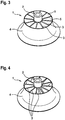
- Fig. 4 finally shows the completed capped impeller 1.
- a fourth step of the method is performed, in which the support structure 5 is removed.
- the support structure 5 is in particular made of a material that is easily corrodible.
- the support structure 5 is made of a material which is corrodible with water.
- the support structure 5 can be washed out very easily with water.
- thermally sprayed magnesium with steel is known because both materials give a readily corrodible composite material.
- the last step of the inventive method according to the preferred embodiment is very simple and time-saving feasible.
Description
Die vorliegende Anmeldung betrifft ein Verfahren zur Herstellung von gedeckelten Laufrädern, insbesondere von gedeckelten Impellern oder Blisks.The present application relates to a method for the production of capped wheels, in particular of capped impellers or blisks.
Laufräder, insbesondere Impeller oder Blisks, kommen in Strömungsmaschinen zum Einsatz, um Fluide durch mechanische Arbeit zu verdichten, oder um durch das entspannen von Fluiden mechanische Arbeit zu verrichten. Laufräder können offen ausgeführt sein, was bedeutet, dass die Schaufeln tangential zu einem stationären Gehäuse rotieren oder geschlossen, wobei die Schaufeln fest mit einem Gehäuse verbunden sind. Geschlossene Laufräder haben gegenüber offenen Laufrädern einen höheren Wirkungsgrad, da hier der Reibungswiderstand des Fluids zu dem stationären Gehäuse geringer ausfällt.Impellers, especially impellers or blisks, are used in turbomachinery to compress fluids by mechanical work or to perform mechanical work by relaxing fluids. Impellers can be made open, which means that the blades rotate or close tangentially to a stationary casing, with the blades being fixedly connected to a casing. Closed wheels have a higher efficiency compared to open wheels, since here the frictional resistance of the fluid to the stationary housing is lower.
Es sind verschiedene Herstellungsverfahren für geschlossene Impeller bekannt. So können die Strömungskanäle beispielsweise durch ein Gießverfahren hergestellt werden. Hierbei ist allerdings in hinterschnittigen Bereichen keine Nacharbeit möglich. Bei dünnwandigen Strukturen sind darüber hinaus der Maßhaltigkeit Grenzen gesetzt.There are several known methods for producing closed impellers. Thus, the flow channels can be produced for example by a casting process. However, no rework is possible in undercut areas. With thin-walled structures dimensional limitations are also limited.
In
Weiterhin findet häufig das Schweißen der Laufräder aus zwei oder mehr Teilen Anwendung. Hierbei werden die Einzelteile des Laufrads konventionell zerspant und dann so gefügt, dass das geschlossene Laufrad entsteht. Nachteilig an Schweißverfahren sind die Schweißnähte selbst, die sich als potentielle Schwachstelle erweisen können und der Verzug am Bauteil, der durch den hohen thermischen Energieeintrag entsteht.Furthermore, often the welding of the wheels of two or more parts application. Here, the individual parts of the impeller are conventionally machined and then joined so that the closed impeller is created. A disadvantage of welding processes are the welds themselves, which can prove to be a potential weak point and the distortion on the component, which results from the high thermal energy input.
Eine weitere Fügemethode der Laufräder ist das Löten, wodurch der starke Verzug des Schweißens verhindert werden kann. Hier ist allerdings die Lötstelle immer auch eine potentielle Schwachstelle.Another joining method of the wheels is the soldering, whereby the strong distortion of the welding can be prevented. Here, however, the solder joint is always a potential vulnerability.
Weiterhin ist aus
In der
Aufgabe der Erfindung ist es, ein Verfahren zur Herstellung von gedeckelten Laufrädern bereitzustellen, das eine geringe Fertigungszeit aufweist und eine definierte Oberflächengüte im Strömungskanal liefert. Des Weiteren sollen fertigungsbedingte Schwachstellen, wie insbesondere Schweißnähte oder Lötstellen, vermieden werden.The object of the invention is to provide a method for the production of capped wheels, which has a low production time and provides a defined surface quality in the flow channel. Furthermore, production-related weak points, such as in particular welds or solder joints, should be avoided.
Die Lösung dieser Aufgabe erfolgt durch die Merkmale des unabhängigen Anspruchs.The solution of this object is achieved by the features of the independent claim.
Ein konventionelles offenes Laufrad wird mit einer Stützstruktur verfüllt, so dass ein Randbereich der Schaufeln mit der Stützstruktur bündig abschließt. Die dadurch entstehende Fläche dient als Substrat für einen generativen Fertigungsprozess. Dadurch wird die geringe Fertigungsdauer und hohe Oberflächengüte bei der zerspanenden Fertigung von offenen Impellern oder Blisks kombiniert mit den Gestaltungsmöglichkeiten eines generativen Fertigungsverfahrens. Des Weiteren entfallen fertigungsbedingte Schwachstellen wie Schweißnähte oder Lötstellen. Das Aufbringen der Stützstruktur erfolgt mittels Kaltgasspritzen. Dabei werden metallische Partikel mit einem Trägergas auf Überschallgeschwindigkeit beschleunigt, indem das komprimierte Trägergas, insbesondere mittels einer Lavaldüse, entspannt wird und dabei hohe Gasgeschwindigkeiten erreicht.A conventional open impeller is filled with a support structure, so that an edge region of the blades is flush with the support structure. The resulting surface serves as a substrate for an additive manufacturing process. As a result, the short production time and high surface quality in the machining production of open impellers or blisks are combined with the design possibilities of a generative manufacturing process. Furthermore, production-related weaknesses such as welds or solder joints are eliminated. The application of the support structure by means of cold gas spraying. In this case, metallic particles are accelerated with a carrier gas to supersonic speed by the compressed carrier gas, in particular by means of a Laval nozzle, is relaxed and thereby reaches high gas velocities.
Dadurch, dass die metallischen Partikel beim Aufprall auf das Substrat nicht aufgeschmolzen werden, sind die thermischen Spannungen geringer und der Verzug des Bauteils kleiner.The fact that the metallic particles are not melted upon impact with the substrate, the thermal stresses are lower and the distortion of the component smaller.
Es hat sich überraschend gezeigt, dass die Oberfläche, die als Substrat für den generativen Fertigungsprozess dient, selbst bei einer Herstellung mittels Kaltgasspritzen eine hervorragende Güte zum Durchführen des generativen Fertigungsprozesses aufweist. Somit ist durch die Verwendung des Kaltgasspritzens einerseits ein Verfahren mit wenig Aufwand vorhanden, das durch geringe thermische Spannungen sehr bauteilschonend ist, wobei andererseits die Durchführung des generativen Fertigungsprozesses direkt auf der kaltgasgespritzten Stützstruktur ausgeführt werden kann. Somit ist insbesondere ein zusätzlicher, aufwendiger Schritt der Oberflächenbearbeitung der Stützstruktur vermieden.It has surprisingly been found that the surface, which serves as a substrate for the generative manufacturing process, even with a production by means of cold gas spraying has an excellent quality for performing the generative manufacturing process. Thus, the use of the cold gas spraying on the one hand, a method with little effort available, which is very component gentle due to low thermal stresses, on the other hand, the implementation of generative manufacturing process can be performed directly on the cold gas injected support structure. Thus, in particular an additional, complex step of the surface treatment of the support structure is avoided.
Der Begriff generatives Fertigungsverfahren bezeichnet hierbei ein Urformen von Erzeugnissen aus formlosem Material, wie insbesondere Flüssigkeiten oder Pulver, oder formneutralem, insbesondere band- oder drahtförmigem, Material mittels chemischer und/oder physikalischer Prozesse.The term generative manufacturing process refers here to a primary molding of products of informal material, such as in particular liquids or powders, or form neutral, in particular band or wire-shaped material by means of chemical and / or physical processes.
Mit dem erfindungsgemäßen Verfahren ist die Herstellung von geschlossenen Laufrädern nicht mehr durch die Erreichbarkeit mit Zerspanungswerkzeugen beschränkt, da offene Laufräder auch mit komplizierten Schaufelformen mit konventionellen Zerspanmethoden gut herstellbar sind.With the method according to the invention, the production of closed wheels is no longer limited by the accessibility with cutting tools, since open wheels are easy to produce even with complicated blade shapes with conventional Zerspanmethoden.
Die Unteransprüche haben bevorzugte Weiterbildungen der Erfindung zum Inhalt.The dependent claims have preferred developments of the invention to the content.
Das erfindungsgemäße Verfahren umfasst vorteilhafterweise die folgenden Schritte. Diese werden insbesondere in der dargestellten Reihenfolge ausgeführt. Zunächst wird ein offenes Laufrad bereitgestellt. Insbesondere ist das Laufrad mit konventionellen Fertigungsmethoden gefertigt. In einem nächsten Schritt wird eine Stützstruktur auf das Laufrad aufgebracht, um die beschriebene Oberfläche zu erzeugen. Schließlich erfolgt bevorzugt die Durchführung des generativen Fertigungsprozesses zum Aufbringen einer Deckschicht auf die Oberfläche.The method according to the invention advantageously comprises the following steps. These are executed in particular in the order shown. First, an open impeller is provided. In particular, the impeller is manufactured using conventional manufacturing methods. In a next step, a support structure is applied to the impeller to produce the described surface. Finally, it is preferable to carry out the generative manufacturing process for applying a cover layer to the surface.
Besonders vorteilhaft wird zusätzlich ein Schritt ausgeführt, indem die Stützstruktur entfernt wird. Die Stützstruktur wird insbesondere durch Korrosion entfernt. Somit ist ein gedeckeltes Laufrad vorhanden, wobei insbesondere keine fertigungsbedingten Schwachstellen vorhanden sind.Particularly advantageously, a step is additionally carried out by the support structure is removed. The support structure is removed in particular by corrosion. Thus, a capped impeller is present, in particular, no production-related weaknesses are present.
Weiterhin ist besonders vorteilhaft vorgesehen, dass die Oberfläche vor Durchführung des generativen Fertigungsprozesses spanend bearbeitet wird. So ist insbesondere die Außenkontur von Schaufeln des offenen Laufrads bearbeitbar. Das erfindungsgemäße Verfahren erlaubt somit auf einfache Art und Weise, die Geometrie des offenen Laufrads vor Aufbringen der Deckschicht zu verändern.Furthermore, it is particularly advantageous that the surface is machined before carrying out the generative production process. Thus, in particular, the outer contour of blades of the open impeller is machined. The inventive method thus allows in a simple manner to change the geometry of the open impeller before applying the cover layer.
Das offene Laufrad und/oder die Deckschickt sind vorteilhafterweise aus metallischen Werkstoffen gefertigt. Alternativ ist das erfindungsgemäße Verfahren auch auf andere Werkstoffe, wie insbesondere Kunststoff, anwendbar, so dass das offene Laufrad und/oder die Deckschicht bevorzugt auch aus diesen anderen Werkstoffen gefertigt sein können.The open impeller and / or the Deckschickt are advantageously made of metallic materials. Alternatively, the method according to the invention can also be applied to other materials, in particular plastic, so that the open running wheel and / or the cover layer can preferably also be made from these other materials.
In einer Ausführungsform der Erfindung handelt es sich bei dem generativen Prozess um Kaltgasspritzen. Besonders vorteilhaft erfolgt somit sowohl das Aufbringen der Stützstruktur als auch das Aufbringen der Deckschicht mittels demselben Verfahren, nämlich dem Kaltgasspritzen. Dabei ist vorteilhafterweise das zu verwendende Material unterschiedlich, so dass sich das Material der Stützstruktur von dem Material der Deckschicht unterscheidet. Durch die Verwendung eines einheitlichen Verfahrens ist der gesamte Herstellungsprozess sehr einfach und kostengünstig, da lediglich eine maschinelle Vorrichtung zur Durchführung eines Verfahrens bereitgehalten werden muss. Zur weiteren Ausgestaltung der Erfindung wird ein mit Wasser korrodierbares Material als Stützstruktur verwendet. Insbesondere bildet thermisch gespritztes Magnesium mit Stahl einen leicht korrodierbaren Werkstoffverbund. Dieser lässt sich schnell mit Wasser auswaschen und ist daher unproblematischer als die Verwendung von Salpetersäure, und weniger aufwendig als abrasives Wasserstrahlen.In one embodiment of the invention, the generative process is cold gas spraying. Thus, both the application of the support structure and the application of the cover layer by means of the same method, namely the cold gas spraying, are carried out particularly advantageously. In this case, advantageously, the material to be used is different, so that the material of the support structure differs from the material of the cover layer. By using a uniform method, the entire manufacturing process is very simple and inexpensive, since only a mechanical device for carrying out a process has to be kept ready. For further embodiment of the invention, a water-corrodible material is used as a support structure. In particular, thermally sprayed magnesium with steel forms an easily corrodible composite material. This can be quickly washed out with water and is therefore less problematic than the use of nitric acid, and less expensive than abrasive water jets.
Ein Randbereich der Schaufeln des offenen Laufrads ist vorteilhafterweise derart geformt, dass eine formschlüssige Kraftübertragung der Deckschicht an die Schaufeln gewährleistet ist. Dazu sind die Randbereiche der Schaufeln vorteilhafterweise mit einer konvexen Kontur versehen. Somit werden lokale Spannungsspitzen innerhalb des gedeckelten Laufrads vermieden, da durch den Formschluss bereits eine Kraftübertragung möglich ist.An edge region of the blades of the open impeller is advantageously shaped such that a positive force transmission of the cover layer is ensured to the blades. For this purpose, the edge regions of the blades are advantageously provided with a convex contour. Thus, local voltage peaks are avoided within the capped impeller, as already by the positive connection a power transmission is possible.
Weiterhin ist bevorzugt vorgesehen, dass das gedeckelte Laufrad ein gedeckelter Impeller oder ein gedeckelter Blisk ist.Furthermore, it is preferably provided that the capped impeller is a capped impeller or a capped blisk.
Schließlich ist bevorzugt vorgesehen, dass das offene Laufrad zerspanend hergestellt wird. Somit erfolgt besonders bevorzugt der zuvor genannte Schritt des Bereitstellens des offenen Laufrads derart, dass ein zerspanend hergestelltes offenes Laufrad bereitgestellt wird. Alternativ ist bevorzugt vorgesehen, dass dieser Schritt durch die zerspanende Herstellung eines offenen Laufrads ersetzt wird.Finally, it is preferably provided that the open impeller is produced by machining. Thus, particularly preferably, the aforementioned step of providing the open impeller is such as to provide a machined open impeller. Alternatively, it is preferably provided that this step is replaced by the machining production of an open impeller.
Die Erfindung wird nun anhand eines Ausführungsbeispiels unter Berücksichtigung der beigefügten Zeichnungen im Detail beschrieben. In den Zeichnungen ist:
- Fig. 1
- eine schematische Darstellung eines offenen Laufrads während eines ersten Schritts des Verfahrens gemäß einem bevorzugten Ausführungsbeispiel der Erfindung,
- Fig. 2
- eine schematische Darstellung eines offenen Laufrads während eines zweiten Schritts des Verfahrens gemäß dem bevorzugten Ausführungsbeispiel der Erfindung,
- Fig. 3
- eine schematische Darstellung eines gedeckelten Laufrads gemäß einem dritten Schritt des Verfahrens gemäß dem bevorzugten Ausführungsbeispiel der Erfindung, und
- Fig. 4
- eine schematische Darstellung eines gedeckelten Laufrads gemäß einem vierten Schritt des Verfahrens gemäß dem bevorzugten Ausführungsbeispiel der Erfindung.
- Fig. 1
- 1 is a schematic representation of an open impeller during a first step of the method according to a preferred embodiment of the invention;
- Fig. 2
- a schematic representation of an open impeller during a second step of the method according to the preferred embodiment of the invention,
- Fig. 3
- a schematic representation of a capped impeller according to a third step of the method according to the preferred embodiment of the invention, and
- Fig. 4
- a schematic representation of a capped impeller according to a fourth step of the method according to the preferred embodiment of the invention.
In einem zweiten Schritt wird auf das offene Laufrad 2 eine Stützstruktur 5 aufgebracht. Durch das Aufbringen der Stützstruktur 5 werden Zwischenräume der Schaufeln 3 verfüllt. Somit entsteht eine Oberfläche 6, wobei eine Oberfläche der Stützstruktur 5 bündig mit den Außenkonturen der Schaufeln 3 ist. Die Außenkonturen der Schaufeln 3 werden mit einer konvexen Kontur versehen, so dass eine Deckschicht 4 (vgl.
Das Aufbringen der Stützstruktur 5 erfolgt mittels Kaltgasspritzen. Somit entfällt eine aufwendige Anfertigung von Behältern, die insbesondere für metallische Pulver benötigt werden. Verglichen mit einem heißisostatischen Pressen ist das Aufbringen der Stützstruktur gemäß dem bevorzugten Ausführungsbeispiel der Erfindung sehr einfach, kostengünstig und zeitsparend möglich. Außerdem erlaubt das Kaltgasspritzen, thermische Spannungen zu reduzieren und damit einen Verzug des offenen Laufrads 2 zu minimieren.The application of the
Die Oberfläche 6 kann vor dem in
In
Es ist somit ersichtlich, dass das gezeigte Verfahren sehr zeitsparend und einfach und damit kostengünstig durchführbar ist. Weiterhin werden thermische Belastungen des gedeckelten Laufrads 1 minimiert, so dass dieses nur einen geringen Verzug und dafür eine lange Lebenserwartung aufweist.It is thus apparent that the method shown is very time-saving and easy and therefore inexpensive to carry out. Furthermore, thermal loads on the covered impeller 1 are minimized, so that this has only a small delay and therefore a long life expectancy.
- 11
- gedeckeltes Laufradcapped impeller
- 22
- offenes Laufradopen impeller
- 33
- Schaufelshovel
- 44
- Deckschichttopcoat
- 55
- Stützstruktursupport structure
- 66
- Oberflächesurface
Claims (10)
- A method for manufacturing capped running wheels (1), wherein an open running wheel (2) is filled with a support structure (5), so that at least an edge region of blades (3) of the open running wheel (2) is flush with the support structure (5), wherein the surface (6) created by that serves as a substrate for a generative manufacturing process, and wherein the support structure (5) is applied by means of cold gas spraying.
- The method according to claim 1, characterised by the steps of:- providing an open running wheel (2),- applying a support structure (5) onto the open running wheel (2) to create the surface (6),- performing the generative manufacturing process to apply a cover layer (4) onto the surface (6).
- The method according to claim 2, characterised by the step of:- removing the support structure (5), in particular by corrosion.
- The method according to claim 2 or 3, characterised in that, prior to performing the generative manufacturing process, the surface (6) is machined.
- The method according to any one of the preceding claims, characterised in that the open running wheel (2) and/or the cover layer (4) are manufactured from a metallic material.
- The method according to any one of the preceding claims, characterised in that the generative process is cold gas spraying.
- The method according to any one of the preceding claims, characterised in that the support structure is manufactured from a material corrodible by water.
- The method according to any one of the preceding claims, characterised in that an edge region of blades (3) of the open running wheel (2) is shaped such that a positive power transmission from the cover layer (4) to the blades (3) is guaranteed.
- The method according to any one of the preceding claims, characterised in that the capped running wheel (1) is a capped impeller or a capped blisk.
- The method according to any one of the preceding claims, characterised in that the open running wheel (2) is manufactured by chipping.
Applications Claiming Priority (1)
| Application Number | Priority Date | Filing Date | Title |
|---|---|---|---|
| DE102015207017.4A DE102015207017B4 (en) | 2015-04-17 | 2015-04-17 | Method for producing covered wheels |
Publications (2)
| Publication Number | Publication Date |
|---|---|
| EP3081669A1 EP3081669A1 (en) | 2016-10-19 |
| EP3081669B1 true EP3081669B1 (en) | 2018-08-29 |
Family
ID=55642334
Family Applications (1)
| Application Number | Title | Priority Date | Filing Date |
|---|---|---|---|
| EP16163083.5A Not-in-force EP3081669B1 (en) | 2015-04-17 | 2016-03-31 | Method for the preparation of capped impellers |
Country Status (2)
| Country | Link |
|---|---|
| EP (1) | EP3081669B1 (en) |
| DE (1) | DE102015207017B4 (en) |
Families Citing this family (6)
| Publication number | Priority date | Publication date | Assignee | Title |
|---|---|---|---|---|
| DE102017209229B4 (en) | 2017-05-31 | 2020-07-16 | Hermle Maschinenbau Gmbh | Process for producing a component and intermediate product in the production of a component |
| CN107755987A (en) * | 2017-11-24 | 2018-03-06 | 中国航发沈阳黎明航空发动机有限责任公司 | A kind of processing technology of aero-engine high-pressure compressor rectifier |
| IT201900007758A1 (en) * | 2019-05-31 | 2020-12-01 | Nuovo Pignone Tecnologie Srl | IMPELLER RING REINFORCED BY COLD DEPOSITION |
| CN110732846B (en) * | 2019-10-26 | 2020-07-03 | 浙江上风高科专风实业有限公司 | Production optimization method for centrifugal fan |
| EP4001657A1 (en) * | 2020-11-24 | 2022-05-25 | Nuovo Pignone Technologie S.r.l. | Cold spray reinforced impeller shroud |
| WO2024041754A1 (en) * | 2022-08-24 | 2024-02-29 | Cryostar Sas | Method for manufacturing an impeller and impeller |
Family Cites Families (8)
| Publication number | Priority date | Publication date | Assignee | Title |
|---|---|---|---|---|
| DE102006049216A1 (en) * | 2006-10-18 | 2008-04-24 | Mtu Aero Engines Gmbh | High-pressure turbine rotor and method for producing a high-pressure turbine rotor |
| WO2009058836A1 (en) * | 2007-10-29 | 2009-05-07 | Hormel Foods Corporation | Packaging of meat products with modified atmospheres |
| US8128865B2 (en) * | 2007-10-31 | 2012-03-06 | Solar Turbines Inc. | Process of making a shrouded impeller |
| EP2177298A1 (en) * | 2008-10-20 | 2010-04-21 | Sulzer Markets and Technology AG | Manufacturing procedure for closed discs |
| DE102010048336A1 (en) * | 2010-10-13 | 2012-04-19 | Mtu Aero Engines Gmbh | Component and method for forming, repairing and / or constructing such a component |
| JP2013224703A (en) * | 2012-04-23 | 2013-10-31 | Nissan Motor Co Ltd | Torque converter housing container |
| US20140169971A1 (en) * | 2012-12-18 | 2014-06-19 | Hamilton Sundstrand Corporation | Additively manufactured impeller |
| DE102014012480B4 (en) * | 2014-08-27 | 2016-06-09 | Rosswag Gmbh | Manufacturing process for a blading of a turbomachine, blading a turbomachine and impeller |
-
2015
- 2015-04-17 DE DE102015207017.4A patent/DE102015207017B4/en not_active Expired - Fee Related
-
2016
- 2016-03-31 EP EP16163083.5A patent/EP3081669B1/en not_active Not-in-force
Also Published As
| Publication number | Publication date |
|---|---|
| DE102015207017B4 (en) | 2017-04-27 |
| DE102015207017A1 (en) | 2016-10-20 |
| EP3081669A1 (en) | 2016-10-19 |
Similar Documents
| Publication | Publication Date | Title |
|---|---|---|
| EP3081669B1 (en) | Method for the preparation of capped impellers | |
| EP2782705B1 (en) | Method of generative producing a component using a laser beam before, during and after the assembly | |
| EP1771275B1 (en) | Method for repairing a component | |
| EP2493650A2 (en) | Method and device for producing a component of a turbomachine | |
| DE102011080187A1 (en) | A method of producing a blade for a turbomachine and blade for a turbomachine | |
| EP3216546A1 (en) | Micro-forging in a generative production method | |
| DE102008052030A1 (en) | Method for connecting at least one turbine blade with a turbine disk or a turbine ring | |
| EP2422051A2 (en) | Method for producing a hard coating of a gas turbine blade tip and gas turbine blade | |
| EP3321011B1 (en) | Method for improving the surface quality of components made by additive manufacturing | |
| EP2344298B1 (en) | Method for replacing an inner disk element of an integrally bladed disk | |
| EP0036202A2 (en) | Process for producing turbo-rotors | |
| DE102010034337A1 (en) | Method for connecting a turbine blade with a turbine disk or a turbine ring | |
| DE102007056259A1 (en) | Laser welding or sintering procedure for producing three-dimensional workpieces e.g. molds and direct steel components, comprises applying steel powders on an underlay and then transferring into a welding phase by focused radiation | |
| EP3381593B1 (en) | Method for selective beam-based melting or sintering | |
| DE102007062557A1 (en) | Method for producing an integrally bladed rotor and rotor | |
| WO2022189286A1 (en) | Manufacture of an impeller in a hybrid process | |
| EP2934806B1 (en) | Friction stir welding tool, method for manufacturing the same, and friction stir welding method | |
| EP2399006A1 (en) | Method for the production of an integrally bladed rotor, and rotor | |
| EP3972774A1 (en) | Electron-beam welding nickel-based superalloys, and device | |
| EP3248727A1 (en) | Turbine blade and method of manufacture the turbine blade | |
| WO2024051969A1 (en) | Impeller for a flow machine and method for producing an impeller | |
| EP4334059A1 (en) | Surface forming process for additively produced structures | |
| EP3972772A1 (en) | Electron-beam welding of nickel-based superalloys, and device | |
| WO2021083640A1 (en) | Component and method for producing a component of this type by means of additive manufacturing | |
| WO2010057475A1 (en) | Method for producing and/or repairing a rotor of a turbo-engine and rotor for the same |
Legal Events
| Date | Code | Title | Description |
|---|---|---|---|
| PUAI | Public reference made under article 153(3) epc to a published international application that has entered the european phase |
Free format text: ORIGINAL CODE: 0009012 |
|
| AK | Designated contracting states |
Kind code of ref document: A1 Designated state(s): AL AT BE BG CH CY CZ DE DK EE ES FI FR GB GR HR HU IE IS IT LI LT LU LV MC MK MT NL NO PL PT RO RS SE SI SK SM TR |
|
| AX | Request for extension of the european patent |
Extension state: BA ME |
|
| STAA | Information on the status of an ep patent application or granted ep patent |
Free format text: STATUS: REQUEST FOR EXAMINATION WAS MADE |
|
| 17P | Request for examination filed |
Effective date: 20170308 |
|
| RBV | Designated contracting states (corrected) |
Designated state(s): AL AT BE BG CH CY CZ DE DK EE ES FI FR GB GR HR HU IE IS IT LI LT LU LV MC MK MT NL NO PL PT RO RS SE SI SK SM TR |
|
| GRAP | Despatch of communication of intention to grant a patent |
Free format text: ORIGINAL CODE: EPIDOSNIGR1 |
|
| STAA | Information on the status of an ep patent application or granted ep patent |
Free format text: STATUS: GRANT OF PATENT IS INTENDED |
|
| RIC1 | Information provided on ipc code assigned before grant |
Ipc: F04D 29/22 20060101ALI20180221BHEP Ipc: F04D 29/18 20060101ALI20180221BHEP Ipc: F01D 5/04 20060101ALI20180221BHEP Ipc: F04D 29/26 20060101ALI20180221BHEP Ipc: F04D 29/02 20060101ALI20180221BHEP Ipc: F01D 5/02 20060101ALI20180221BHEP Ipc: F01D 5/34 20060101ALI20180221BHEP Ipc: C23C 24/04 20060101AFI20180221BHEP Ipc: F04D 29/28 20060101ALI20180221BHEP |
|
| INTG | Intention to grant announced |
Effective date: 20180327 |
|
| GRAS | Grant fee paid |
Free format text: ORIGINAL CODE: EPIDOSNIGR3 |
|
| GRAA | (expected) grant |
Free format text: ORIGINAL CODE: 0009210 |
|
| STAA | Information on the status of an ep patent application or granted ep patent |
Free format text: STATUS: THE PATENT HAS BEEN GRANTED |
|
| AK | Designated contracting states |
Kind code of ref document: B1 Designated state(s): AL AT BE BG CH CY CZ DE DK EE ES FI FR GB GR HR HU IE IS IT LI LT LU LV MC MK MT NL NO PL PT RO RS SE SI SK SM TR |
|
| REG | Reference to a national code |
Ref country code: GB Ref legal event code: FG4D Free format text: NOT ENGLISH |
|
| REG | Reference to a national code |
Ref country code: CH Ref legal event code: EP |
|
| REG | Reference to a national code |
Ref country code: AT Ref legal event code: REF Ref document number: 1035223 Country of ref document: AT Kind code of ref document: T Effective date: 20180915 |
|
| REG | Reference to a national code |
Ref country code: IE Ref legal event code: FG4D Free format text: LANGUAGE OF EP DOCUMENT: GERMAN |
|
| REG | Reference to a national code |
Ref country code: DE Ref legal event code: R096 Ref document number: 502016001784 Country of ref document: DE |
|
| REG | Reference to a national code |
Ref country code: CH Ref legal event code: NV Representative=s name: KELLER AND PARTNER PATENTANWAELTE AG, CH |
|
| REG | Reference to a national code |
Ref country code: NL Ref legal event code: MP Effective date: 20180829 |
|
| REG | Reference to a national code |
Ref country code: LT Ref legal event code: MG4D |
|
| PG25 | Lapsed in a contracting state [announced via postgrant information from national office to epo] |
Ref country code: FI Free format text: LAPSE BECAUSE OF FAILURE TO SUBMIT A TRANSLATION OF THE DESCRIPTION OR TO PAY THE FEE WITHIN THE PRESCRIBED TIME-LIMIT Effective date: 20180829 Ref country code: GR Free format text: LAPSE BECAUSE OF FAILURE TO SUBMIT A TRANSLATION OF THE DESCRIPTION OR TO PAY THE FEE WITHIN THE PRESCRIBED TIME-LIMIT Effective date: 20181130 Ref country code: SE Free format text: LAPSE BECAUSE OF FAILURE TO SUBMIT A TRANSLATION OF THE DESCRIPTION OR TO PAY THE FEE WITHIN THE PRESCRIBED TIME-LIMIT Effective date: 20180829 Ref country code: NL Free format text: LAPSE BECAUSE OF FAILURE TO SUBMIT A TRANSLATION OF THE DESCRIPTION OR TO PAY THE FEE WITHIN THE PRESCRIBED TIME-LIMIT Effective date: 20180829 Ref country code: BG Free format text: LAPSE BECAUSE OF FAILURE TO SUBMIT A TRANSLATION OF THE DESCRIPTION OR TO PAY THE FEE WITHIN THE PRESCRIBED TIME-LIMIT Effective date: 20181129 Ref country code: RS Free format text: LAPSE BECAUSE OF FAILURE TO SUBMIT A TRANSLATION OF THE DESCRIPTION OR TO PAY THE FEE WITHIN THE PRESCRIBED TIME-LIMIT Effective date: 20180829 Ref country code: NO Free format text: LAPSE BECAUSE OF FAILURE TO SUBMIT A TRANSLATION OF THE DESCRIPTION OR TO PAY THE FEE WITHIN THE PRESCRIBED TIME-LIMIT Effective date: 20181129 Ref country code: LT Free format text: LAPSE BECAUSE OF FAILURE TO SUBMIT A TRANSLATION OF THE DESCRIPTION OR TO PAY THE FEE WITHIN THE PRESCRIBED TIME-LIMIT Effective date: 20180829 Ref country code: IS Free format text: LAPSE BECAUSE OF FAILURE TO SUBMIT A TRANSLATION OF THE DESCRIPTION OR TO PAY THE FEE WITHIN THE PRESCRIBED TIME-LIMIT Effective date: 20181229 |
|
| PG25 | Lapsed in a contracting state [announced via postgrant information from national office to epo] |
Ref country code: LV Free format text: LAPSE BECAUSE OF FAILURE TO SUBMIT A TRANSLATION OF THE DESCRIPTION OR TO PAY THE FEE WITHIN THE PRESCRIBED TIME-LIMIT Effective date: 20180829 Ref country code: AL Free format text: LAPSE BECAUSE OF FAILURE TO SUBMIT A TRANSLATION OF THE DESCRIPTION OR TO PAY THE FEE WITHIN THE PRESCRIBED TIME-LIMIT Effective date: 20180829 Ref country code: HR Free format text: LAPSE BECAUSE OF FAILURE TO SUBMIT A TRANSLATION OF THE DESCRIPTION OR TO PAY THE FEE WITHIN THE PRESCRIBED TIME-LIMIT Effective date: 20180829 |
|
| PG25 | Lapsed in a contracting state [announced via postgrant information from national office to epo] |
Ref country code: ES Free format text: LAPSE BECAUSE OF FAILURE TO SUBMIT A TRANSLATION OF THE DESCRIPTION OR TO PAY THE FEE WITHIN THE PRESCRIBED TIME-LIMIT Effective date: 20180829 Ref country code: EE Free format text: LAPSE BECAUSE OF FAILURE TO SUBMIT A TRANSLATION OF THE DESCRIPTION OR TO PAY THE FEE WITHIN THE PRESCRIBED TIME-LIMIT Effective date: 20180829 Ref country code: PL Free format text: LAPSE BECAUSE OF FAILURE TO SUBMIT A TRANSLATION OF THE DESCRIPTION OR TO PAY THE FEE WITHIN THE PRESCRIBED TIME-LIMIT Effective date: 20180829 Ref country code: CZ Free format text: LAPSE BECAUSE OF FAILURE TO SUBMIT A TRANSLATION OF THE DESCRIPTION OR TO PAY THE FEE WITHIN THE PRESCRIBED TIME-LIMIT Effective date: 20180829 Ref country code: RO Free format text: LAPSE BECAUSE OF FAILURE TO SUBMIT A TRANSLATION OF THE DESCRIPTION OR TO PAY THE FEE WITHIN THE PRESCRIBED TIME-LIMIT Effective date: 20180829 |
|
| PG25 | Lapsed in a contracting state [announced via postgrant information from national office to epo] |
Ref country code: SM Free format text: LAPSE BECAUSE OF FAILURE TO SUBMIT A TRANSLATION OF THE DESCRIPTION OR TO PAY THE FEE WITHIN THE PRESCRIBED TIME-LIMIT Effective date: 20180829 Ref country code: DK Free format text: LAPSE BECAUSE OF FAILURE TO SUBMIT A TRANSLATION OF THE DESCRIPTION OR TO PAY THE FEE WITHIN THE PRESCRIBED TIME-LIMIT Effective date: 20180829 Ref country code: SK Free format text: LAPSE BECAUSE OF FAILURE TO SUBMIT A TRANSLATION OF THE DESCRIPTION OR TO PAY THE FEE WITHIN THE PRESCRIBED TIME-LIMIT Effective date: 20180829 |
|
| REG | Reference to a national code |
Ref country code: DE Ref legal event code: R097 Ref document number: 502016001784 Country of ref document: DE |
|
| PLBE | No opposition filed within time limit |
Free format text: ORIGINAL CODE: 0009261 |
|
| STAA | Information on the status of an ep patent application or granted ep patent |
Free format text: STATUS: NO OPPOSITION FILED WITHIN TIME LIMIT |
|
| 26N | No opposition filed |
Effective date: 20190531 |
|
| PG25 | Lapsed in a contracting state [announced via postgrant information from national office to epo] |
Ref country code: SI Free format text: LAPSE BECAUSE OF FAILURE TO SUBMIT A TRANSLATION OF THE DESCRIPTION OR TO PAY THE FEE WITHIN THE PRESCRIBED TIME-LIMIT Effective date: 20180829 |
|
| PG25 | Lapsed in a contracting state [announced via postgrant information from national office to epo] |
Ref country code: MC Free format text: LAPSE BECAUSE OF FAILURE TO SUBMIT A TRANSLATION OF THE DESCRIPTION OR TO PAY THE FEE WITHIN THE PRESCRIBED TIME-LIMIT Effective date: 20180829 |
|
| PG25 | Lapsed in a contracting state [announced via postgrant information from national office to epo] |
Ref country code: LU Free format text: LAPSE BECAUSE OF NON-PAYMENT OF DUE FEES Effective date: 20190331 |
|
| REG | Reference to a national code |
Ref country code: BE Ref legal event code: MM Effective date: 20190331 |
|
| PG25 | Lapsed in a contracting state [announced via postgrant information from national office to epo] |
Ref country code: IE Free format text: LAPSE BECAUSE OF NON-PAYMENT OF DUE FEES Effective date: 20190331 |
|
| PG25 | Lapsed in a contracting state [announced via postgrant information from national office to epo] |
Ref country code: BE Free format text: LAPSE BECAUSE OF NON-PAYMENT OF DUE FEES Effective date: 20190331 |
|
| PG25 | Lapsed in a contracting state [announced via postgrant information from national office to epo] |
Ref country code: TR Free format text: LAPSE BECAUSE OF FAILURE TO SUBMIT A TRANSLATION OF THE DESCRIPTION OR TO PAY THE FEE WITHIN THE PRESCRIBED TIME-LIMIT Effective date: 20180829 |
|
| PGFP | Annual fee paid to national office [announced via postgrant information from national office to epo] |
Ref country code: IT Payment date: 20200325 Year of fee payment: 5 Ref country code: GB Payment date: 20200325 Year of fee payment: 5 |
|
| PGFP | Annual fee paid to national office [announced via postgrant information from national office to epo] |
Ref country code: CH Payment date: 20200325 Year of fee payment: 5 |
|
| PG25 | Lapsed in a contracting state [announced via postgrant information from national office to epo] |
Ref country code: MT Free format text: LAPSE BECAUSE OF FAILURE TO SUBMIT A TRANSLATION OF THE DESCRIPTION OR TO PAY THE FEE WITHIN THE PRESCRIBED TIME-LIMIT Effective date: 20180829 Ref country code: PT Free format text: LAPSE BECAUSE OF FAILURE TO SUBMIT A TRANSLATION OF THE DESCRIPTION OR TO PAY THE FEE WITHIN THE PRESCRIBED TIME-LIMIT Effective date: 20181229 |
|
| PGFP | Annual fee paid to national office [announced via postgrant information from national office to epo] |
Ref country code: FR Payment date: 20200325 Year of fee payment: 5 |
|
| PGFP | Annual fee paid to national office [announced via postgrant information from national office to epo] |
Ref country code: DE Payment date: 20200326 Year of fee payment: 5 |
|
| REG | Reference to a national code |
Ref country code: CH Ref legal event code: PFA Owner name: HERMLE MASCHINENBAU GMBH, DE Free format text: FORMER OWNER: HERMLE MASCHINENBAU GMBH, DE |
|
| PG25 | Lapsed in a contracting state [announced via postgrant information from national office to epo] |
Ref country code: CY Free format text: LAPSE BECAUSE OF FAILURE TO SUBMIT A TRANSLATION OF THE DESCRIPTION OR TO PAY THE FEE WITHIN THE PRESCRIBED TIME-LIMIT Effective date: 20180829 |
|
| PG25 | Lapsed in a contracting state [announced via postgrant information from national office to epo] |
Ref country code: HU Free format text: LAPSE BECAUSE OF FAILURE TO SUBMIT A TRANSLATION OF THE DESCRIPTION OR TO PAY THE FEE WITHIN THE PRESCRIBED TIME-LIMIT; INVALID AB INITIO Effective date: 20160331 |
|
| REG | Reference to a national code |
Ref country code: DE Ref legal event code: R119 Ref document number: 502016001784 Country of ref document: DE |
|
| REG | Reference to a national code |
Ref country code: CH Ref legal event code: PL |
|
| GBPC | Gb: european patent ceased through non-payment of renewal fee |
Effective date: 20210331 |
|
| PG25 | Lapsed in a contracting state [announced via postgrant information from national office to epo] |
Ref country code: DE Free format text: LAPSE BECAUSE OF NON-PAYMENT OF DUE FEES Effective date: 20211001 Ref country code: FR Free format text: LAPSE BECAUSE OF NON-PAYMENT OF DUE FEES Effective date: 20210331 Ref country code: GB Free format text: LAPSE BECAUSE OF NON-PAYMENT OF DUE FEES Effective date: 20210331 Ref country code: CH Free format text: LAPSE BECAUSE OF NON-PAYMENT OF DUE FEES Effective date: 20210331 Ref country code: LI Free format text: LAPSE BECAUSE OF NON-PAYMENT OF DUE FEES Effective date: 20210331 |
|
| PG25 | Lapsed in a contracting state [announced via postgrant information from national office to epo] |
Ref country code: IT Free format text: LAPSE BECAUSE OF NON-PAYMENT OF DUE FEES Effective date: 20210331 |
|
| REG | Reference to a national code |
Ref country code: AT Ref legal event code: MM01 Ref document number: 1035223 Country of ref document: AT Kind code of ref document: T Effective date: 20210331 |
|
| PG25 | Lapsed in a contracting state [announced via postgrant information from national office to epo] |
Ref country code: MK Free format text: LAPSE BECAUSE OF FAILURE TO SUBMIT A TRANSLATION OF THE DESCRIPTION OR TO PAY THE FEE WITHIN THE PRESCRIBED TIME-LIMIT Effective date: 20180829 |
|
| PG25 | Lapsed in a contracting state [announced via postgrant information from national office to epo] |
Ref country code: AT Free format text: LAPSE BECAUSE OF NON-PAYMENT OF DUE FEES Effective date: 20210331 |
|
| P01 | Opt-out of the competence of the unified patent court (upc) registered |
Effective date: 20230413 |