EP3081447B1 - Intelligent gap setting for adaptive cruise control - Google Patents
Intelligent gap setting for adaptive cruise control Download PDFInfo
- Publication number
- EP3081447B1 EP3081447B1 EP15163486.2A EP15163486A EP3081447B1 EP 3081447 B1 EP3081447 B1 EP 3081447B1 EP 15163486 A EP15163486 A EP 15163486A EP 3081447 B1 EP3081447 B1 EP 3081447B1
- Authority
- EP
- European Patent Office
- Prior art keywords
- gap
- preset
- adaption
- vehicle
- vehicles
- Prior art date
- Legal status (The legal status is an assumption and is not a legal conclusion. Google has not performed a legal analysis and makes no representation as to the accuracy of the status listed.)
- Active
Links
- 230000003044 adaptive effect Effects 0.000 title description 9
- 230000007613 environmental effect Effects 0.000 claims description 28
- 238000000034 method Methods 0.000 claims description 19
- 230000006978 adaptation Effects 0.000 claims description 18
- 230000010355 oscillation Effects 0.000 claims description 9
- 238000010276 construction Methods 0.000 claims description 7
- 230000003247 decreasing effect Effects 0.000 claims description 7
- 238000012937 correction Methods 0.000 claims description 4
- 239000000654 additive Substances 0.000 claims description 3
- 230000000996 additive effect Effects 0.000 claims description 3
- 230000006866 deterioration Effects 0.000 claims description 2
- 229910052739 hydrogen Inorganic materials 0.000 description 3
- 230000000630 rising effect Effects 0.000 description 3
- 230000001133 acceleration Effects 0.000 description 2
- 238000004891 communication Methods 0.000 description 2
- 230000001276 controlling effect Effects 0.000 description 2
- 238000010972 statistical evaluation Methods 0.000 description 2
- 241001465754 Metazoa Species 0.000 description 1
- 230000001419 dependent effect Effects 0.000 description 1
- 238000011161 development Methods 0.000 description 1
- 238000005516 engineering process Methods 0.000 description 1
- 238000007667 floating Methods 0.000 description 1
- 230000006870 function Effects 0.000 description 1
- 238000010801 machine learning Methods 0.000 description 1
- 238000005259 measurement Methods 0.000 description 1
- 230000007935 neutral effect Effects 0.000 description 1
- 230000003287 optical effect Effects 0.000 description 1
- 238000012545 processing Methods 0.000 description 1
- 230000001105 regulatory effect Effects 0.000 description 1
Images


Classifications
-
- B—PERFORMING OPERATIONS; TRANSPORTING
- B60—VEHICLES IN GENERAL
- B60W—CONJOINT CONTROL OF VEHICLE SUB-UNITS OF DIFFERENT TYPE OR DIFFERENT FUNCTION; CONTROL SYSTEMS SPECIALLY ADAPTED FOR HYBRID VEHICLES; ROAD VEHICLE DRIVE CONTROL SYSTEMS FOR PURPOSES NOT RELATED TO THE CONTROL OF A PARTICULAR SUB-UNIT
- B60W30/00—Purposes of road vehicle drive control systems not related to the control of a particular sub-unit, e.g. of systems using conjoint control of vehicle sub-units, or advanced driver assistance systems for ensuring comfort, stability and safety or drive control systems for propelling or retarding the vehicle
- B60W30/14—Adaptive cruise control
- B60W30/16—Control of distance between vehicles, e.g. keeping a distance to preceding vehicle
-
- B—PERFORMING OPERATIONS; TRANSPORTING
- B60—VEHICLES IN GENERAL
- B60W—CONJOINT CONTROL OF VEHICLE SUB-UNITS OF DIFFERENT TYPE OR DIFFERENT FUNCTION; CONTROL SYSTEMS SPECIALLY ADAPTED FOR HYBRID VEHICLES; ROAD VEHICLE DRIVE CONTROL SYSTEMS FOR PURPOSES NOT RELATED TO THE CONTROL OF A PARTICULAR SUB-UNIT
- B60W2540/00—Input parameters relating to occupants
- B60W2540/215—Selection or confirmation of options
-
- B—PERFORMING OPERATIONS; TRANSPORTING
- B60—VEHICLES IN GENERAL
- B60W—CONJOINT CONTROL OF VEHICLE SUB-UNITS OF DIFFERENT TYPE OR DIFFERENT FUNCTION; CONTROL SYSTEMS SPECIALLY ADAPTED FOR HYBRID VEHICLES; ROAD VEHICLE DRIVE CONTROL SYSTEMS FOR PURPOSES NOT RELATED TO THE CONTROL OF A PARTICULAR SUB-UNIT
- B60W2552/00—Input parameters relating to infrastructure
- B60W2552/15—Road slope
-
- B—PERFORMING OPERATIONS; TRANSPORTING
- B60—VEHICLES IN GENERAL
- B60W—CONJOINT CONTROL OF VEHICLE SUB-UNITS OF DIFFERENT TYPE OR DIFFERENT FUNCTION; CONTROL SYSTEMS SPECIALLY ADAPTED FOR HYBRID VEHICLES; ROAD VEHICLE DRIVE CONTROL SYSTEMS FOR PURPOSES NOT RELATED TO THE CONTROL OF A PARTICULAR SUB-UNIT
- B60W2552/00—Input parameters relating to infrastructure
- B60W2552/30—Road curve radius
-
- B—PERFORMING OPERATIONS; TRANSPORTING
- B60—VEHICLES IN GENERAL
- B60W—CONJOINT CONTROL OF VEHICLE SUB-UNITS OF DIFFERENT TYPE OR DIFFERENT FUNCTION; CONTROL SYSTEMS SPECIALLY ADAPTED FOR HYBRID VEHICLES; ROAD VEHICLE DRIVE CONTROL SYSTEMS FOR PURPOSES NOT RELATED TO THE CONTROL OF A PARTICULAR SUB-UNIT
- B60W2552/00—Input parameters relating to infrastructure
- B60W2552/40—Coefficient of friction
-
- B—PERFORMING OPERATIONS; TRANSPORTING
- B60—VEHICLES IN GENERAL
- B60W—CONJOINT CONTROL OF VEHICLE SUB-UNITS OF DIFFERENT TYPE OR DIFFERENT FUNCTION; CONTROL SYSTEMS SPECIALLY ADAPTED FOR HYBRID VEHICLES; ROAD VEHICLE DRIVE CONTROL SYSTEMS FOR PURPOSES NOT RELATED TO THE CONTROL OF A PARTICULAR SUB-UNIT
- B60W2554/00—Input parameters relating to objects
- B60W2554/40—Dynamic objects, e.g. animals, windblown objects
- B60W2554/404—Characteristics
- B60W2554/4042—Longitudinal speed
-
- B—PERFORMING OPERATIONS; TRANSPORTING
- B60—VEHICLES IN GENERAL
- B60W—CONJOINT CONTROL OF VEHICLE SUB-UNITS OF DIFFERENT TYPE OR DIFFERENT FUNCTION; CONTROL SYSTEMS SPECIALLY ADAPTED FOR HYBRID VEHICLES; ROAD VEHICLE DRIVE CONTROL SYSTEMS FOR PURPOSES NOT RELATED TO THE CONTROL OF A PARTICULAR SUB-UNIT
- B60W2554/00—Input parameters relating to objects
- B60W2554/40—Dynamic objects, e.g. animals, windblown objects
- B60W2554/406—Traffic density
-
- B—PERFORMING OPERATIONS; TRANSPORTING
- B60—VEHICLES IN GENERAL
- B60W—CONJOINT CONTROL OF VEHICLE SUB-UNITS OF DIFFERENT TYPE OR DIFFERENT FUNCTION; CONTROL SYSTEMS SPECIALLY ADAPTED FOR HYBRID VEHICLES; ROAD VEHICLE DRIVE CONTROL SYSTEMS FOR PURPOSES NOT RELATED TO THE CONTROL OF A PARTICULAR SUB-UNIT
- B60W2554/00—Input parameters relating to objects
- B60W2554/80—Spatial relation or speed relative to objects
- B60W2554/801—Lateral distance
-
- B—PERFORMING OPERATIONS; TRANSPORTING
- B60—VEHICLES IN GENERAL
- B60W—CONJOINT CONTROL OF VEHICLE SUB-UNITS OF DIFFERENT TYPE OR DIFFERENT FUNCTION; CONTROL SYSTEMS SPECIALLY ADAPTED FOR HYBRID VEHICLES; ROAD VEHICLE DRIVE CONTROL SYSTEMS FOR PURPOSES NOT RELATED TO THE CONTROL OF A PARTICULAR SUB-UNIT
- B60W2554/00—Input parameters relating to objects
- B60W2554/80—Spatial relation or speed relative to objects
- B60W2554/802—Longitudinal distance
-
- B—PERFORMING OPERATIONS; TRANSPORTING
- B60—VEHICLES IN GENERAL
- B60W—CONJOINT CONTROL OF VEHICLE SUB-UNITS OF DIFFERENT TYPE OR DIFFERENT FUNCTION; CONTROL SYSTEMS SPECIALLY ADAPTED FOR HYBRID VEHICLES; ROAD VEHICLE DRIVE CONTROL SYSTEMS FOR PURPOSES NOT RELATED TO THE CONTROL OF A PARTICULAR SUB-UNIT
- B60W2554/00—Input parameters relating to objects
- B60W2554/80—Spatial relation or speed relative to objects
- B60W2554/804—Relative longitudinal speed
-
- B—PERFORMING OPERATIONS; TRANSPORTING
- B60—VEHICLES IN GENERAL
- B60W—CONJOINT CONTROL OF VEHICLE SUB-UNITS OF DIFFERENT TYPE OR DIFFERENT FUNCTION; CONTROL SYSTEMS SPECIALLY ADAPTED FOR HYBRID VEHICLES; ROAD VEHICLE DRIVE CONTROL SYSTEMS FOR PURPOSES NOT RELATED TO THE CONTROL OF A PARTICULAR SUB-UNIT
- B60W2555/00—Input parameters relating to exterior conditions, not covered by groups B60W2552/00, B60W2554/00
- B60W2555/20—Ambient conditions, e.g. wind or rain
-
- B—PERFORMING OPERATIONS; TRANSPORTING
- B60—VEHICLES IN GENERAL
- B60W—CONJOINT CONTROL OF VEHICLE SUB-UNITS OF DIFFERENT TYPE OR DIFFERENT FUNCTION; CONTROL SYSTEMS SPECIALLY ADAPTED FOR HYBRID VEHICLES; ROAD VEHICLE DRIVE CONTROL SYSTEMS FOR PURPOSES NOT RELATED TO THE CONTROL OF A PARTICULAR SUB-UNIT
- B60W2556/00—Input parameters relating to data
- B60W2556/10—Historical data
-
- B—PERFORMING OPERATIONS; TRANSPORTING
- B60—VEHICLES IN GENERAL
- B60W—CONJOINT CONTROL OF VEHICLE SUB-UNITS OF DIFFERENT TYPE OR DIFFERENT FUNCTION; CONTROL SYSTEMS SPECIALLY ADAPTED FOR HYBRID VEHICLES; ROAD VEHICLE DRIVE CONTROL SYSTEMS FOR PURPOSES NOT RELATED TO THE CONTROL OF A PARTICULAR SUB-UNIT
- B60W2556/00—Input parameters relating to data
- B60W2556/45—External transmission of data to or from the vehicle
- B60W2556/65—Data transmitted between vehicles
-
- B—PERFORMING OPERATIONS; TRANSPORTING
- B60—VEHICLES IN GENERAL
- B60W—CONJOINT CONTROL OF VEHICLE SUB-UNITS OF DIFFERENT TYPE OR DIFFERENT FUNCTION; CONTROL SYSTEMS SPECIALLY ADAPTED FOR HYBRID VEHICLES; ROAD VEHICLE DRIVE CONTROL SYSTEMS FOR PURPOSES NOT RELATED TO THE CONTROL OF A PARTICULAR SUB-UNIT
- B60W2754/00—Output or target parameters relating to objects
- B60W2754/10—Spatial relation or speed relative to objects
- B60W2754/30—Longitudinal distance
Definitions
- the present invention relates to a method for assisting a driver in driving a vehicle, a driver assistance system, a computer software program product and a vehicle including such driver assistance system.
- US 2002/0161506 discloses a adaptive cruise control regulating the inter vehicle distance according to the environment of the vehicle.
- Conventional adaptive cruise control (ACC) systems control the vehicle speed according to a target speed setting, detect moving objects in the vehicle path, such as preceding vehicles, and provide throttle and brake control, if necessary, to maintain a trailing distance (headway or time gap) from the preceding vehicle.
- ACC adaptive cruise control
- DE 10 2008 061 388 A1 discloses an adaptive cruise control system in which the vehicle speed and the gap can be set and adjusted by the vehicle operator.
- DE 10 2008 061 388 A1 if a preceding vehicle is detected, a gap is selected automatically on basis of the detected distance from the preceding vehicle and the vehicle operator can later adapt the selected gap.
- US 6,622,810 B2 discloses an ACC system that automatically modifies the gap to limit the follow distance to the predecessor in order to keep this predecessor in sensor range.
- EP 2 730 945 Al discloses an ACC system that automatically modifies the gap based on the determined position, velocity and acceleration of both the ego-vehicle and the predecessor and a model comprising statistical noise characteristics of the ego-vehicle sensors to ensure a safe distance in case of strong braking of the predecessor vehicle.
- US2012/0123660A1 discloses a system, in which the amount of traffic is estimated and the inter-vehicle distance and the vehicle speed are set based on the amount.
- EP1317359 B1 discloses an ACC system, in which the gap is increased automatically when low friction is determined by detecting wheel slip using Anti-lock Braking System (ABS), traction control and vehicle stability control.
- ABS Anti-lock Braking System
- US6445153B1 discloses an ACC system that determines a driving surface coefficient of friction based on a driven wheel speed of the vehicle and that automatically modifies the gap based on the driving surface coefficient of friction.
- the vehicle operator/driver can adapt the gap to the preceding vehicle manually by choosing from a small number of gap settings. In this way, the driver can use dedicated different gap sizes for different environmental conditions.
- the driver might prefer a smaller gap to the preceding vehicle than in normal traffic situations in order to prevent frequent cut-ins of other vehicles or in order to raise capacity utilization of the road.
- the driver often has to adapt the gap setting of the ACC manually, which can be uncomfortable.
- a method for assisting a driver in driving a vehicle comprising the steps of:
- the ego-distance and distances between other vehicles can be estimated; and in the determining step, a gap adaption indicator can be determined based on the difference between the ego-distance and an average of the distances between the other vehicles and/or other statistical evaluation of distances between vehicles including minimum distance G min , maximum distance G max , range of G max - G min , and/or the trend/development of the distances estimated at different times.
- At least one of the environmental conditions of oscillation in velocity of the detected object, traffic density, gap size between other vehicles, distance to successor of ego-vehicle, road shape such as a curve/inclination, road surface state, construction site and time of day is estimated; wherein each of an increased oscillation in velocity of the detected object, an increased traffic density, a gap size between other vehicles larger than the preset gap, a distance to the successor of the ego-vehicle larger than the preset gap, beginning of a curve, deterioration in the road surface state, beginning of a construction site and beginning of night-time period is associated to a respective gap adaption indicator indicating an extension of the preset gap; and each of a decreased oscillation in velocity of the detected object, a decreased traffic density, the gap size between other vehicles smaller that the preset gap, a distance to the successor of the ego-vehicle smaller that the preset gap, an end of a curve, an improved road surface state, an end of construction site and end
- a plurality of the gap adaption indicators based on a plurality of the estimated environmental conditions can be determined; and in the adjusting step, the preset gap can be adjusted based on an overall gap adaption indicator determined from the plurality of the gap adaption indicators.
- current gap setting n can be switched to gap setting n-lout of the set [n min ,...,n max ], if n > n min and the gap adaption indicators indicate to reduce the preset gap; and current gap setting n can be switched to gap setting n+1 out of the set [n min ,...,n max ], if n ⁇ n max and the gap adaption indicators indicate to enlarge the preset gap.
- the method can further comprise the steps of detecting a manual adjustment of the preset gap; and storing current environmental conditions associated to the manual adjustment.
- At least current geographic location of the ego-vehicle and current time of day associated to the manual adjustment can be stored and, when a geographic location that corresponds to the stored geographic location or a time of day that corresponds to the stored time of day are estimated in the estimating step, in the determining step, a gap adaption indicator indicating an adjustment of the preset gap that corresponds to the manual adjustment can be determined.
- the method can further comprise the steps of receiving at least one of the current gap size applied by a driver, the current time of day, and the current geographical location of at least one other vehicle (B.,D.); storing all received gap sizes categorized by time and location; and calculating the average gap size, minimum gap size and/or maximum gap size applied for each time and location.
- driver assistance system means for receiving user input to switch on/off automatic gap adaptation and means for receiving user input indicating an additive or multiplicative offset to the automatically determined gap can be provided.
- the vehicle according to the present invention includes such driver assistance system comprising means for producing sensor data by at least one sensor; means for physically sensing the environment of a host vehicle and/or by obtaining data conveying information about the environment of a host vehicle; means for detecting an object in a path of the host vehicle based on the sensor data; means for controlling a distance between the host vehicle and the detected object based on a preset gap; means for estimating environmental conditions of the host vehicle based on the sensor data; means for determining gap adaption indicators associated to the estimated environmental conditions, wherein each of the gap adaption indicators indicates an extension or a reduction of the preset gap; and means for adjusting the preset gap based on the gap adaption indicators.
- the computer software program product according to the present invention performs, when executed on a computer, performs the method according to claim 1.
- a vehicle equipped with a driver assistance system may be referred to herein as "host-vehicle” or "ego-vehicle".
- the host vehicle or ego-vehicle may be a car, truck, bus or motorcycle, or in general any object that can use active cruise control.
- the vehicles may include manned vehicles driven by a driver but also automatically driven vehicles such as robot vehicles.
- the term "driver assistance system” is to be understood herein as including in general any kind of driving assistance system which may be employed in unmanned vehicles as well.
- the detected objects may include any kind of moving objects such as other vehicles, cars, trucks, busses, motor/cyclists, robotic vehicles, but also trolleys, pedestrians, and even animals such as horses.
- the objects may be detected by any kind of sensor equipment or circuitry hosted by the ego-vehicle.
- the object under consideration may be referred to herein as "target object” or "target vehicle”.
- the gap and headway are a measurement of the distance or time between vehicles. In the adaptive cruise control, the gap or headway can be controlled to maintain a constant value or to maintain a safety distance (or another distance) that is dependent on the velocity of the ego-vehicle.
- Fig. 1 illustrates a first traffic situation 1A with vehicles A, B, C, D and E traveling on a road 1 with two lanes and a second situation 1B with vehicles A, B, C, D, E, F, G, H, I and P traveling on the road 1.
- the ego-vehicle E is equipped with a conventional ACC system and a desired gap is preset by the driver of the ego-vehicle E.
- the ACC system of the ego-vehicle E controls the distance between the ego-vehicle E and the ACC target vehicle A based on the preset gap and the velocities of the ego-vehicle E and predecessor A.
- the traffic densities are different and the ego-vehicle E follows the ACC target vehicle A at the same distance.
- the preset gap t GAP fits the light traffic well.
- vehicle C will recognize a fitting gap between vehicles E and A but also that behind ego-vehicle E there is plenty of free lane.
- vehicle C lets ego-vehicle E pass and change lane behind ego-vehicle E.
- the same gap t GAP is used in a more dense traffic in situation 1B.
- situation 1B the gaps between the other vehicles A, B, F, G, C, D, H, I and the gap between the successor vehicle P and the ego-vehicle E are smaller than the preset gap t GAP .
- a larger gap t GAP can be "incomprehensible" to other drivers and can provoke cut-ins of, e.g. vehicle C or "pushing" of the very close successor vehicle P.
- the driver assistance system automatically detects whether the current gap size fits the driving condition or whether it needs to be adapted (reduced or enlarged).
- the system uses a set of indicators like current traffic situation, geographic location, etc. to determine the need for gap size adaptation.
- the driver assistance system in a second step, adapts the gap settings.
- This adaptation can be either done in discrete steps (e.g., by choosing between predetermined gap settings or adapt the gap size in predefined discrete steps) or, alternatively, by estimating the optimal gap setting from the observed vicinity or predefined values (e.g., a statistically determined gap size for a certain geographic location) or a combination thereof.
- Fig. 2 shows an embodiment of the driver assistance system according to the present invention.
- the driver assistance system is mounted on the ego-vehicle E and is preferably integrated with existing systems of such host vehicle.
- controls such as an accelerator or motor management, power steering or a braking system may be used by the driver assistance system according to the present invention.
- the driver assistance system shown in Fig. 2 comprises at least one sensor 2 which is capable of physically sensing the environment of the ego-vehicle E.
- sensor 2 for example a radar sensor, produces data that allow analyzing a relative position and orientation of a target vehicle as well as the current speed of the sensed target object.
- the ego-vehicle E Since it is difficult to have only one sensor 2 which is capable of sensing the entire environment of the host vehicle and thereby covering an area on both sides of the ego-vehicle E as well as the forward direction and the rearward direction, it is preferred to have a plurality of sensors.
- the plurality of sensors may but do not need to be of the same type.
- optical sensors 3 are present so that the environment of the host vehicle can be analyzed by using image processing.
- the ego-vehicle E is already equipped with sensor 2 and/or sensor 3 that are needed for other assistance or comfort functions, these sensors may be used in common.
- the driver assistance system further comprises a manual speed input unit 4, a target speed setting unit 5, a target speed computing unit 6, a target gap computing unit 7 and a traffic situation assessment unit 8.
- the throttle 9 and the brake 10 indicated by a dotted line in Fig. 2 are controlled by the driver assistance system but are not elements of the driver assistance system.
- the manual speed input unit 4 is advantageously for vehicles driven by a driver and is not essential for automatically driven vehicles such as robot vehicles.
- the manual speed input unit 4 can include a set switch for setting the current speed as the set-speed, a resume switch for resuming the speed which was selected in the previous operation of the Adaptive Cruise Control (ACC) and a cancel switch for deactivating the cruise control.
- ACC Adaptive Cruise Control
- cancel switch for deactivating the cruise control.
- the target speed setting unit 5 receives commands for the target speed from the target speed computing unit 6 and from the manual speed input unit 4 and sets a target speed of the ego-vehicle E according to the commands.
- the target speed setting unit 5 sends a corresponding command signal to the throttle 9 of the engine and, optionally, to the brake 10 of the ego-vehicle E so that either the target speed or the set-speed is achieved and maintained, depending on which speed is lower.
- the target speed computing unit 6 receives sensor data from the sensor 2 and/or 3 and determines the traveling speed of the ego-vehicle E that is required to maintain the gap given by the target gap computing unit 7 at a particular value. Based on the sensor data, the target gap computing unit 7 determines a target gap between the ego-vehicle E and the target vehicle A. This value of the gap may be determined from the traveling speed of the ego-vehicle E and possibly other factors, such as weather conditions, road conditions and personal preferences which might be given by manual input as, for example, the gap setting. It is to be noted that the gap can be defined as a time period between the point in time when the target vehicle passes a particular point and when the ego vehicle passes the same point. This result is an automated correction of the gap length with respect to actual speed.
- the traffic situation assessment unit 8 receives sensor data from the (on-board) sensor 2 and/or 3 of the ego-vehicle E and/or from external sensors, e.g. sensors of another vehicle or an external traffic information system (not shown), estimates environment conditions of the ego-vehicle E based on the sensor data, assigns the estimated environment conditions to respective indicators indicating an extension or a reduction of the current (preset) gap and determines whether the current gap size fits the current traffic condition or in how far it needs to be adapted (reduced or enlarged) based on the indicators.
- external sensors e.g. sensors of another vehicle or an external traffic information system
- the required deviation from a current (neutral) gap setting is provided to the target gap computing unit 7.
- the needed deviation could be encoded as floating point number between -1,0 and 1,0 (-1,0: reduce the gap size to minimum, 0: no adaptation, 1,0: enlarge the gap size to a maximum) or integer steps in case of discrete gap size settings (e.g. -5 to +5).
- the target gap computing unit 7 can be adapted to receive (e.g. by switch or menu entry) commands from the driver (user) to turn on/off the gap size adaptation. For example, if the gap size adaptation is switched off, the output from the traffic situation assessment unit 8 is ignored.
- the extension or reduction of the current (preset) gap indicated by the adaptation indicators can be carried out, for example, by changing between predetermined gap settings (variant 1) or by switching from constant gap values to continuous gap values (variant 2).
- the target gap computing unit 7 switches from gap setting n (if n > n min ) to gap setting n-1, if traffic situation assessment unit 8 suggests to reduce the gap and the target gap computing unit 7 switches from gap setting n (if n ⁇ n max ) to gap setting n+1, if traffic situation assessment unit 8 suggests to enlarge the selected gap.
- the target gap computing unit 7 can be adapted to switch back to the initially selected gap setting (setting "G2": 2,2s) if the traffic situation assessment unit 8 no longer suggests to adapt (reduce/enlarge) the initially selected gap size to the current traffic flow or if no signal is output from the traffic situation assessment unit 8 due to a system failure.
- the smallest unity/step that can be switched/set is 0,2s.
- the target gap computing unit 7 can adapt the gap setting in steps that are different from the gap settings G1..G5.
- the selected gap G2 can be adapted in smaller steps (e.g., -0,1s/+0,1s) or in larger steps (e.g., -0,3s/+0,3s) with respect to the gap settings G1..G5 (-0,2s/+0,2s).
- the target gap computing unit 7 can be adapted to reduce the gap setting G2 in small steps (e.g., - 0,1s) and to enlarge the selected gap G2 in large steps (e.g., +0,3s; or switching from "G2" to "G4").
- the target gap computing unit 7 switches from constant gap values to continuous gap values, wherein the time gap value for each gap setting gets adapted. If the traffic situation assessment unit 8 suggests adapting (reduce/enlarge) the initially selected gap size to the current traffic flow (environment conditions) and, for example, gap setting "2" out of the gap settings "1": 2s, "2": 2,4s and "3”: 2,8s has been chosen by the user, the target gap computing unit 7 keeps gap setting "2", but changes gap setting "2" to 2,2s and gap setting "3" to 2,5s. Gap setting "1" is not reduced, because it is already the legal minimum.
- the target gap computing unit 7 adapts the value of gap setting n (if n > 1) to a value ⁇ [value(gap setting n-1), ..., value(gap setting n)) if traffic situation assessment unit 8 suggests to reduce the gap and the target gap computing unit 7 adapts the value of gap setting n (if n ⁇ n max ) to a value ⁇ [value(gap setting n), ..., value(gap setting n+1)] if traffic situation assessment unit 8 suggests to enlarge the selected gap.
- the target gap computing unit 7 can be adapted to switch back to the initial gap sizes if the traffic situation assessment unit 8 no longer suggests to adapt (reduce/enlarge) the initial gap sizes to the current traffic flow or in case of system failure.
- the traffic situation assessment unit 8 estimates the environment conditions of the ego-vehicle E based on the sensor data to adapt the current gap size (reduce or enlarge) or to maintain/confirm the current gap size.
- One, some or all of the following environment conditions can be estimated by the traffic situation assessment unit 8:
- Each condition can be associated to a gap adaption indicator indicating an extension n+1 or n+2, or ..., of the current gap setting n or a reduction n-1 or n-2, or ..., of the current gap setting n.
- a gap adaption indicator can be calculated by subtracting the current gap size from a reference/recommended gap size determined based on the environmental condition. For example, the recommended gap size can be determined based on the gap sizes between other vehicles (average gap size, minimum gap size, maximum gap, trend etc.) or based on the gap sizes between other vehicles and the velocity of the ego-vehicle E.
- a combination of all gap adaption indicators can be used to determine whether the current gap size is to be adapted or maintained. In this way, when the combination of gap adaption indicators indicating an extension and gap adaption indicators indicating a reduction is balanced, gap adaption is not necessary/indicated. For example, if in situation 1B shown in Fig.
- the gap adaption indicator associated to the gap between the successor vehicle P and the ego-vehicle E indicates a reduction of the preset gap t GAP of -0,2s because the gap between the successor vehicle P and the ego-vehicle E is smaller than the preset gap t GAP and the gap adaption indicator associated to the trend of the gaps between the preceding vehicles A, B, F, D, H, I indicates a rising of the preset gap t GAP of +0,2s, the combination of the gap adaption indicators indicates a gap adaption of ⁇ 0s; i.e., gap adaption is not necessary/indicated.
- the gap adaption indicator associated to the gap between the successor vehicle P and the ego-vehicle E indicates a reduction of the preset gap T GAP of -0,2s
- the gap adaption indicator associated to the trend of the gaps between the preceding vehicles A, B, F, D, H, I indicates a rising of the preset gap t GAP of +0,2s
- the gap adaption indicator associated to the road properties indicates a rising of the preset gap t GAP of +0,1s
- the combination of the gap adaption indicators indicates a gap adaption of the preset gap t GAP of +0,1s.
- the gap adaptation indicators might be weighted to account for e.g. reliability of the indicators or user preferences, etc., or might be combined in a more complex manner e.g. by using machine learning techniques.
- the gap adaption indicators (amount and/or polarity of adaption and/or weighted) associated to the environmental conditions can be preset by the manufacturer of the ego-vehicle E or by the user (driver). Further, the preset gap adaption indicators can be manually changed by the user (driver) and/or can be automatically changed in line with a manual user correction of a gap that was adapted/set by the target gap computing unit 7 based on the estimated environmental conditions.
- each manual gap setting/adaption by the user can be detected and associated to current environmental conditions for statistical evaluation, wherein the environmental conditions including, for example, the current geographic location and the current time of day can be used to generate/update statistical data.
- the statistical data are used to adapt and/or set the gap size.
- gap setting/adaption and/or the statistical data can be collected from other vehicles that are equipped with the corresponding sensors via C2X or any other communication technology connectivity.
- Such statistical data can be generated by the steps of:
- the gap size of the ego-vehicle E can be adapted to the average gap size usually applied by the driver(s) for the current time of day and for the current geographic location.
- the average gap sizes could be, e.g., provided via connectivity or stored on a local storage on the ego-vehicle E and updated via connectivity.
- the traffic situation assessment unit 8 can be adapted to determine whether or not the current gap size is to be adapted based on the statistical data, current gaps between other (neighbor) vehicles or other environmental conditions and the target gap computing unit 7 can be adapted to receive (e.g. by switch or menu entry) commands for selecting one of the determination modes.
- the target gap computing unit 7 can be adapted to receive user input to switch on/off automatic gap adaptation; to receive user input as additive offset to the automatically determined gap; or to receive user input as factor with the automatically determined gap and/or can be adapted to mix user input and automatically determined gap by weighted average.
- the traffic situation assessment unit 8 can be adapted to calculate a continuous gap directly.
- an average gap of the surrounding vehicles can be set as continuous gap; a gap proportional to: gap_target - (average of observed gaps to predecessor vehicle A - gap_target) can be set as continuous gap, which covers "oscillations in velocity" with limited number of observations; or a gap proportional to: 0,5 ⁇ (gap_ego_successor + gap_ego_predecessor) can be set as continuous gap, which covers "pushing of ego-vehicle” and leads to a balance gap between predecessor and the ego-vehicle E.
- the continuous gap can be incrementally adapted by, for example, increment/decrement gap by fixed amount; increment/decrement gap by amount proportional to indication confidence; and reducing the gap in small steps, increase in large steps.
- the gap can be decreased in case of: increasing traffic density (e.g. proportional to number of observed vehicles) or the traffic density is within a certain range; traffic jam or slow-moving traffic (to maximize utilization of road capacity) and pushing of other vehicles, and can be increased in case of: decreasing traffic density (traffic density is within a certain range); strong oscillations in velocity of predecessor, other vehicles, or the ego-vehicle E; bad road condition, night time and curvy road.
- increasing traffic density e.g. proportional to number of observed vehicles
- traffic density e.g. proportional to number of observed vehicles
- traffic jam or slow-moving traffic to maximize utilization of road capacity
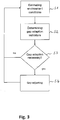
- Fig. 3 shows a flowchart illustrating an example of gap adaptation operation according to the present invention which can be combined with any conventional adaptive cruise control method.
- the traffic situation assessment unit 8 estimates environmental conditions of the ego-vehicle E based on the sensor data received from the (on-board) sensor 2 and/or 3 of the ego-vehicle E and/or from external sensors or an external traffic information system (e.g. TMC, GPS).
- an external traffic information system e.g. TMC, GPS
- step S2 indicators assigned to the estimated environmental conditions are determined based on the statistical data or a table in which one or more environmental conditions are associated to a respective indicator indicating amount and/or polarity of adaption and the weighting and combination of the indicators (total gap adaptation indicator) is calculated from the determined indicators as described above.
- an average gap size can be calculated from environmental conditions indicating current gap sizes between other vehicles and a gap adaptation indicator indicating the average gap size can be generated.
- it is determined whether or not adaptation of the preset gap is necessary This can be performed by determining whether or not the total gap adaptation indicator indicates an extension/reduction or by determining whether or not the average gap size is larger or smaller than the preset gap. If an adaptation is necessary, the preset gap is adjusted based on the gap adaptation indicator in step S4. This can be performed by the variant 1 or 2, or other methods as described above.
- Fig. 4 shows a first traffic situation 2A that corresponds to the first traffic situation 1A shown in Fig. 1 .
- the ego-vehicle E is equipped with the driver assistance system according to the present invention and a desired gap is preset by the driver of the ego-vehicle E.
- the traffic densities are different and the ego-vehicle E follows the ACC target vehicle A with an automatically adapted gap t GAP .
- the gap t GAP is chosen according to the traffic situation.
- the system chooses a larger gap for the light traffic to ensure high comfort, high safety driving.
- Situation 2B the system reduces the gap in dense traffic. This leads to higher acceptance by other drivers, reduces cut-ins from adjacent lanes and minimizes "pushing" of the ego-vehicle's successor P.
Description
- The present invention relates to a method for assisting a driver in driving a vehicle, a driver assistance system, a computer software program product and a vehicle including such driver assistance system.
-
US 2002/0161506 discloses a adaptive cruise control regulating the inter vehicle distance according to the environment of the vehicle. - Conventional adaptive cruise control (ACC) systems control the vehicle speed according to a target speed setting, detect moving objects in the vehicle path, such as preceding vehicles, and provide throttle and brake control, if necessary, to maintain a trailing distance (headway or time gap) from the preceding vehicle.
-
DE 10 2008 061 388 A1 discloses an adaptive cruise control system in which the vehicle speed and the gap can be set and adjusted by the vehicle operator. InDE 10 2008 061 388 A1 , if a preceding vehicle is detected, a gap is selected automatically on basis of the detected distance from the preceding vehicle and the vehicle operator can later adapt the selected gap. -
US 6,622,810 B2 discloses an ACC system that automatically modifies the gap to limit the follow distance to the predecessor in order to keep this predecessor in sensor range. -
EP 2 730 945 -
US2012/0123660A1 discloses a system, in which the amount of traffic is estimated and the inter-vehicle distance and the vehicle speed are set based on the amount.EP1317359 B1 discloses an ACC system, in which the gap is increased automatically when low friction is determined by detecting wheel slip using Anti-lock Braking System (ABS), traction control and vehicle stability control. -
US6445153B1 discloses an ACC system that determines a driving surface coefficient of friction based on a driven wheel speed of the vehicle and that automatically modifies the gap based on the driving surface coefficient of friction. - In conventional adaptive cruise control systems, the vehicle operator/driver can adapt the gap to the preceding vehicle manually by choosing from a small number of gap settings. In this way, the driver can use dedicated different gap sizes for different environmental conditions.
- For example, in case of a confusing traffic situation or very low traffic density, a driver might prefer a larger gap to the preceding vehicle than in normal traffic situations in order to feel more comfortable.
- In case of very dense traffic, the driver might prefer a smaller gap to the preceding vehicle than in normal traffic situations in order to prevent frequent cut-ins of other vehicles or in order to raise capacity utilization of the road.
- Particularly if the driving/environmental conditions change frequently, the driver often has to adapt the gap setting of the ACC manually, which can be uncomfortable.
- It is an object of the present invention to provide a method for assisting a driver in driving a vehicle, a driver assistance system, a computer software program product and a vehicle including such driver assistance system with which gap size can be adapted to different environmental conditions automatically.
- This object is achieved by the inventive method for assisting a driver in driving a vehicle, a driver assistance system, a computer software program product and a vehicle including such driver assistance system according to the enclosed independent claims. Advantageous features of the present invention are defined in the corresponding subclaims.
- According to the present invention, a method for assisting a driver in driving a vehicle, comprising the steps of:
- producing sensor data by at least one sensor physically sensing the environment of a host vehicle and/ or by obtaining data conveying information about the environment of a host vehicle;
- detecting an object in a path of the host vehicle based on the sensor data;
- controlling a distance between the host vehicle and the detected object based on a preset gap;
- estimating environmental conditions of the host vehicle based on the sensor data;
- determining gap adaption indicators associated to the estimated environmental conditions, wherein each of the gap adaption indicators indicates an extension or a reduction of the preset gap; and
- ajusting the preset gap based on the gap adaption indicators,
- detecting a manual adjustment of the preset gap; and
- storing current environmental conditions associated to the manual adjustment; wherein at least the current geographic location of the ego-vehicle and the current time of day associated to the manual adjustment are stored and, when a geographic location that corresponds to the stored geographic location or a time of day that corresponds to the stored time of day are estimated in the estimating step, in the determining step, a gap adaption indicator indicating an adjustment of the preset gap that corresponds to the manual adjustment is determined; and
- in the estimating step, an ego-distance between the ego-vehicle and the detected object and distances between other vehicles are estimated; and
- in the determining step, a gap adaption indicator is determined based on the difference between the ego-vehicle time gap and an average of the time gaps between the other vehicles, minimum of the time gaps between the other vehicles and/or maximum of the time gaps between the other vehicles.
- Further, in the estimating step, the ego-distance and distances between other vehicles can be estimated; and in the determining step, a gap adaption indicator can be determined based on the difference between the ego-distance and an average of the distances between the other vehicles and/or other statistical evaluation of distances between vehicles including minimum distance Gmin, maximum distance Gmax, range of Gmax - Gmin, and/or the trend/development of the distances estimated at different times.
- In another advantageous embodiment, in the estimating step, at least one of the environmental conditions of oscillation in velocity of the detected object, traffic density, gap size between other vehicles, distance to successor of ego-vehicle, road shape such as a curve/inclination, road surface state, construction site and time of day is estimated; wherein each of an increased oscillation in velocity of the detected object, an increased traffic density, a gap size between other vehicles larger than the preset gap, a distance to the successor of the ego-vehicle larger than the preset gap, beginning of a curve, deterioration in the road surface state, beginning of a construction site and beginning of night-time period is associated to a respective gap adaption indicator indicating an extension of the preset gap; and each of a decreased oscillation in velocity of the detected object, a decreased traffic density, the gap size between other vehicles smaller that the preset gap, a distance to the successor of the ego-vehicle smaller that the preset gap, an end of a curve, an improved road surface state, an end of construction site and end of night-time period is associated to a respective gap adaption indicator indicating a reduction of the preset gap.
- In the determining step, a plurality of the gap adaption indicators based on a plurality of the estimated environmental conditions can be determined; and in the adjusting step, the preset gap can be adjusted based on an overall gap adaption indicator determined from the plurality of the gap adaption indicators.
- When the preset gap corresponds to one of gap settings selectable by a user, in the adjusting step, current gap setting n can be switched to gap setting n-lout of the set [nmin,...,nmax], if n > nmin and the gap adaption indicators indicate to reduce the preset gap; and current gap setting n can be switched to gap setting n+1 out of the set [nmin,...,nmax], if n < nmax and the gap adaption indicators indicate to enlarge the preset gap.
- When the preset gap corresponds to one of the gap settings nmin to nmax selectable by a user, in the adjusting step, gap size associated to each gap setting n > nmin can be reduced if the gap adaption indicators indicate to reduce the preset gap (tGAP); and gap size associated to each gap setting n <=nmax can be increased if the gap adaption indicators indicate to enlarge the preset gap).
- The method can further comprise the steps of detecting a manual adjustment of the preset gap; and storing current environmental conditions associated to the manual adjustment.
- Further, at least current geographic location of the ego-vehicle and current time of day associated to the manual adjustment can be stored and, when a geographic location that corresponds to the stored geographic location or a time of day that corresponds to the stored time of day are estimated in the estimating step, in the determining step, a gap adaption indicator indicating an adjustment of the preset gap that corresponds to the manual adjustment can be determined.
- The method can further comprise the steps of receiving at least one of the current gap size applied by a driver, the current time of day, and the current geographical location of at least one other vehicle (B.,D.); storing all received gap sizes categorized by time and location; and calculating the average gap size, minimum gap size and/or maximum gap size applied for each time and location.
- Further, in the driver assistance system means for receiving user input to switch on/off automatic gap adaptation and means for receiving user input indicating an additive or multiplicative offset to the automatically determined gap can be provided.
- The vehicle according to the present invention includes such driver assistance system comprising means for producing sensor data by at least one sensor; means for physically sensing the environment of a host vehicle and/or by obtaining data conveying information about the environment of a host vehicle; means for detecting an object in a path of the host vehicle based on the sensor data; means for controlling a distance between the host vehicle and the detected object based on a preset gap; means for estimating environmental conditions of the host vehicle based on the sensor data; means for determining gap adaption indicators associated to the estimated environmental conditions, wherein each of the gap adaption indicators indicates an extension or a reduction of the preset gap; and means for adjusting the preset gap based on the gap adaption indicators.
- The computer software program product according to the present invention performs, when executed on a computer, performs the method according to claim 1.
- The invention is to be explained more detailed in the following with reference to the accompanying drawing, wherein:
-
Fig. 1 shows a schematic for explaining a functioning of a conventional driver assistance system in a first and second traffic situation; -
Fig. 2 shows, in schematic form, an embodiment of the driver assistance system according to the present invention; and -
Fig. 3 shows a flowchart illustrating an operation of gap adaptation according to the present invention; and -
Fig. 4 shows a schematic for explaining a functioning of the driver assistance system according to the present invention in a first and second traffic situation. - A vehicle equipped with a driver assistance system may be referred to herein as "host-vehicle" or "ego-vehicle". According to the present invention, the host vehicle or ego-vehicle may be a car, truck, bus or motorcycle, or in general any object that can use active cruise control. The vehicles may include manned vehicles driven by a driver but also automatically driven vehicles such as robot vehicles. In this respect, the term "driver assistance system" is to be understood herein as including in general any kind of driving assistance system which may be employed in unmanned vehicles as well.
- Similarly, the detected objects may include any kind of moving objects such as other vehicles, cars, trucks, busses, motor/cyclists, robotic vehicles, but also trolleys, pedestrians, and even animals such as horses. The objects may be detected by any kind of sensor equipment or circuitry hosted by the ego-vehicle. The object under consideration may be referred to herein as "target object" or "target vehicle". The gap and headway are a measurement of the distance or time between vehicles. In the adaptive cruise control, the gap or headway can be controlled to maintain a constant value or to maintain a safety distance (or another distance) that is dependent on the velocity of the ego-vehicle.
-
Fig. 1 illustrates a first traffic situation 1A with vehicles A, B, C, D and E traveling on a road 1 with two lanes and a second situation 1B with vehicles A, B, C, D, E, F, G, H, I and P traveling on the road 1. - In
Fig. 1 , the ego-vehicle E is equipped with a conventional ACC system and a desired gap is preset by the driver of the ego-vehicle E. The ACC system of the ego-vehicle E controls the distance between the ego-vehicle E and the ACC target vehicle A based on the preset gap and the velocities of the ego-vehicle E and predecessor A. In situations 1A and 1B shown inFig. 1 , the traffic densities are different and the ego-vehicle E follows the ACC target vehicle A at the same distance. - In situation 1A, the preset gap tGAP fits the light traffic well. In such traffic situations it can be assumed that vehicle C will recognize a fitting gap between vehicles E and A but also that behind ego-vehicle E there is plenty of free lane. Thus it can be expected that vehicle C lets ego-vehicle E pass and change lane behind ego-vehicle E. The same gap tGAP is used in a more dense traffic in situation 1B. In situation 1B, the gaps between the other vehicles A, B, F, G, C, D, H, I and the gap between the successor vehicle P and the ego-vehicle E are smaller than the preset gap tGAP. Here keeping a larger gap tGAP can be "incomprehensible" to other drivers and can provoke cut-ins of, e.g. vehicle C or "pushing" of the very close successor vehicle P.
- In situation 1B shown in
Fig. 1 , the driver of the ego-vehicle E will prefer a smaller gap, which also raises capacity utilization of the road 1. For reducing the gap tGAP, the driver of the ego-vehicle E has to adapt/change the preset gap manually. If the situations 1A and 1B change frequently, the driver of the ego vehicle E often has to adapt the gap setting of the ACC manually which can be uncomfortable. - With the present invention, different gap sizes for different environmental conditions can be set automatically. The driver assistance system according to the present invention automatically detects whether the current gap size fits the driving condition or whether it needs to be adapted (reduced or enlarged). The system uses a set of indicators like current traffic situation, geographic location, etc. to determine the need for gap size adaptation.
- In case the gap size needs to be adapted, in a second step, the driver assistance system according to the present invention adapts the gap settings. This adaptation can be either done in discrete steps (e.g., by choosing between predetermined gap settings or adapt the gap size in predefined discrete steps) or, alternatively, by estimating the optimal gap setting from the observed vicinity or predefined values (e.g., a statistically determined gap size for a certain geographic location) or a combination thereof.
-
Fig. 2 shows an embodiment of the driver assistance system according to the present invention. The driver assistance system is mounted on the ego-vehicle E and is preferably integrated with existing systems of such host vehicle. In particular, controls such as an accelerator or motor management, power steering or a braking system may be used by the driver assistance system according to the present invention. - The driver assistance system shown in
Fig. 2 comprises at least onesensor 2 which is capable of physically sensing the environment of the ego-vehicleE. Such sensor 2, for example a radar sensor, produces data that allow analyzing a relative position and orientation of a target vehicle as well as the current speed of the sensed target object. - Since it is difficult to have only one
sensor 2 which is capable of sensing the entire environment of the host vehicle and thereby covering an area on both sides of the ego-vehicle E as well as the forward direction and the rearward direction, it is preferred to have a plurality of sensors. The plurality of sensors may but do not need to be of the same type. In the illustrated embodiment in addition toradar sensor 2,optical sensors 3 are present so that the environment of the host vehicle can be analyzed by using image processing. - If the ego-vehicle E is already equipped with
sensor 2 and/orsensor 3 that are needed for other assistance or comfort functions, these sensors may be used in common. - As shown in
Fig. 2 , the driver assistance system further comprises a manual speed input unit 4, a target speed setting unit 5, a target speed computing unit 6, a targetgap computing unit 7 and a traffic situation assessment unit 8. The throttle 9 and the brake 10 indicated by a dotted line inFig. 2 are controlled by the driver assistance system but are not elements of the driver assistance system. The manual speed input unit 4 is advantageously for vehicles driven by a driver and is not essential for automatically driven vehicles such as robot vehicles. - The manual speed input unit 4 can include a set switch for setting the current speed as the set-speed, a resume switch for resuming the speed which was selected in the previous operation of the Adaptive Cruise Control (ACC) and a cancel switch for deactivating the cruise control. By pressing the resume switch and the set-switch for a short duration, the set-speed can be increased and decreased, respectively, by a small increment.
- The target speed setting unit 5 receives commands for the target speed from the target speed computing unit 6 and from the manual speed input unit 4 and sets a target speed of the ego-vehicle E according to the commands. When the Adaptive Cruise Control is in place, the target speed setting unit 5 sends a corresponding command signal to the throttle 9 of the engine and, optionally, to the brake 10 of the ego-vehicle E so that either the target speed or the set-speed is achieved and maintained, depending on which speed is lower.
- The target speed computing unit 6 receives sensor data from the
sensor 2 and/or 3 and determines the traveling speed of the ego-vehicle E that is required to maintain the gap given by the targetgap computing unit 7 at a particular value. Based on the sensor data, the targetgap computing unit 7 determines a target gap between the ego-vehicle E and the target vehicle A. This value of the gap may be determined from the traveling speed of the ego-vehicle E and possibly other factors, such as weather conditions, road conditions and personal preferences which might be given by manual input as, for example, the gap setting. It is to be noted that the gap can be defined as a time period between the point in time when the target vehicle passes a particular point and when the ego vehicle passes the same point. This result is an automated correction of the gap length with respect to actual speed. - The traffic situation assessment unit 8 receives sensor data from the (on-board)
sensor 2 and/or 3 of the ego-vehicle E and/or from external sensors, e.g. sensors of another vehicle or an external traffic information system (not shown), estimates environment conditions of the ego-vehicle E based on the sensor data, assigns the estimated environment conditions to respective indicators indicating an extension or a reduction of the current (preset) gap and determines whether the current gap size fits the current traffic condition or in how far it needs to be adapted (reduced or enlarged) based on the indicators. - The required deviation from a current (neutral) gap setting is provided to the target
gap computing unit 7. For example, the needed deviation could be encoded as floating point number between -1,0 and 1,0 (-1,0: reduce the gap size to minimum, 0: no adaptation, 1,0: enlarge the gap size to a maximum) or integer steps in case of discrete gap size settings (e.g. -5 to +5). - The target
gap computing unit 7 can be adapted to receive (e.g. by switch or menu entry) commands from the driver (user) to turn on/off the gap size adaptation. For example, if the gap size adaptation is switched off, the output from the traffic situation assessment unit 8 is ignored. - The extension or reduction of the current (preset) gap indicated by the adaptation indicators can be carried out, for example, by changing between predetermined gap settings (variant 1) or by switching from constant gap values to continuous gap values (variant 2).
- In variant 1, if traffic situation assessment unit 8 suggests to reduce the selected gap and, for example, gap setting G2 out of the gap settings "G1": 2s; "G2": 2,2s; "G3": 2,4s; "G4": 2,6s; and "G5": 2,8s has been chosen by the user, gap setting "1" (=2s) is chosen by the target
gap computing unit 7. In other words, the targetgap computing unit 7 switches from gap setting n (if n > nmin) to gap setting n-1, if traffic situation assessment unit 8 suggests to reduce the gap and the targetgap computing unit 7 switches from gap setting n (if n < nmax) to gap setting n+1, if traffic situation assessment unit 8 suggests to enlarge the selected gap. In both cases, the targetgap computing unit 7 can be adapted to switch back to the initially selected gap setting (setting "G2": 2,2s) if the traffic situation assessment unit 8 no longer suggests to adapt (reduce/enlarge) the initially selected gap size to the current traffic flow or if no signal is output from the traffic situation assessment unit 8 due to a system failure. In the gap setting as described above, the smallest unity/step that can be switched/set is 0,2s. Alternatively, the targetgap computing unit 7 can adapt the gap setting in steps that are different from the gap settings G1..G5. In this way, if traffic situation assessment unit 8 suggests to reduce/enlarge the selected gap G2, the selected gap G2 can be adapted in smaller steps (e.g., -0,1s/+0,1s) or in larger steps (e.g., -0,3s/+0,3s) with respect to the gap settings G1..G5 (-0,2s/+0,2s). Further, the targetgap computing unit 7 can be adapted to reduce the gap setting G2 in small steps (e.g., - 0,1s) and to enlarge the selected gap G2 in large steps (e.g., +0,3s; or switching from "G2" to "G4"). - In
variant 2, the targetgap computing unit 7 switches from constant gap values to continuous gap values, wherein the time gap value for each gap setting gets adapted. If the traffic situation assessment unit 8 suggests adapting (reduce/enlarge) the initially selected gap size to the current traffic flow (environment conditions) and, for example, gap setting "2" out of the gap settings "1": 2s, "2": 2,4s and "3": 2,8s has been chosen by the user, the targetgap computing unit 7 keeps gap setting "2", but changes gap setting "2" to 2,2s and gap setting "3" to 2,5s. Gap setting "1" is not reduced, because it is already the legal minimum. In other words, the targetgap computing unit 7 adapts the value of gap setting n (if n > 1) to a value ε [value(gap setting n-1), ..., value(gap setting n)) if traffic situation assessment unit 8 suggests to reduce the gap and the targetgap computing unit 7 adapts the value of gap setting n (if n < nmax) to a value ε [value(gap setting n), ..., value(gap setting n+1)] if traffic situation assessment unit 8 suggests to enlarge the selected gap. In both cases, the targetgap computing unit 7 can be adapted to switch back to the initial gap sizes if the traffic situation assessment unit 8 no longer suggests to adapt (reduce/enlarge) the initial gap sizes to the current traffic flow or in case of system failure. - The traffic situation assessment unit 8 estimates the environment conditions of the ego-vehicle E based on the sensor data to adapt the current gap size (reduce or enlarge) or to maintain/confirm the current gap size.
- One, some or all of the following environment conditions can be estimated by the traffic situation assessment unit 8:
- Oscillation in velocity (e.g. in very dense traffic, traffic jam, distracted predecessor) ego-vehicle E needs to accelerate/decelerate "often" to keep a gap to the predecessor,
observed frequent accelerations/decelerations of other traffic participants, - Traffic density
number of perceived vehicles,
velocity difference between lanes (e.g., difference in average velocity of vehicles among lanes),
external information (e.g. Traffic Message Channel (TMC), web service, vehicle-to-vehicle/vehicle-to-infrastructure (V2X) communication), - gap sizes between other vehicles
- ego-vehicle gets "pushed"
distance to successor of ego-vehicle,
ego-vehicle is overtaken on the right-hand side,
other vehicle honks, turns up the headlights, - road properties
curvature of the road,
road surface state,
construction site, - time of day (e.g. day-time vs. night-time), and
- geographic location
special characteristics of road, e.g., curvy, steep inclination,
differences in driving style (e.g. different countries or regional differences within a country). - Each condition can be associated to a gap adaption indicator indicating an extension n+1 or n+2, or ..., of the current gap setting n or a reduction n-1 or n-2, or ..., of the current gap setting n. Further a gap adaption indicator can be calculated by subtracting the current gap size from a reference/recommended gap size determined based on the environmental condition. For example, the recommended gap size can be determined based on the gap sizes between other vehicles (average gap size, minimum gap size, maximum gap, trend etc.) or based on the gap sizes between other vehicles and the velocity of the ego-vehicle E.
- A combination of all gap adaption indicators can be used to determine whether the current gap size is to be adapted or maintained. In this way, when the combination of gap adaption indicators indicating an extension and gap adaption indicators indicating a reduction is balanced, gap adaption is not necessary/indicated. For example, if in situation 1B shown in
Fig. 1 the gap adaption indicator associated to the gap between the successor vehicle P and the ego-vehicle E indicates a reduction of the preset gap tGAP of -0,2s because the gap between the successor vehicle P and the ego-vehicle E is smaller than the preset gap tGAP and the gap adaption indicator associated to the trend of the gaps between the preceding vehicles A, B, F, D, H, I indicates a rising of the preset gap tGAP of +0,2s, the combination of the gap adaption indicators indicates a gap adaption of ±0s; i.e., gap adaption is not necessary/indicated. On the other hand, if the gap adaption indicator associated to the gap between the successor vehicle P and the ego-vehicle E indicates a reduction of the preset gap TGAP of -0,2s, the gap adaption indicator associated to the trend of the gaps between the preceding vehicles A, B, F, D, H, I indicates a rising of the preset gap tGAP of +0,2s, and the gap adaption indicator associated to the road properties indicates a rising of the preset gap tGAP of +0,1s, the combination of the gap adaption indicators indicates a gap adaption of the preset gap tGAP of +0,1s. Additionally, the gap adaptation indicators might be weighted to account for e.g. reliability of the indicators or user preferences, etc., or might be combined in a more complex manner e.g. by using machine learning techniques. - The gap adaption indicators (amount and/or polarity of adaption and/or weighted) associated to the environmental conditions can be preset by the manufacturer of the ego-vehicle E or by the user (driver). Further, the preset gap adaption indicators can be manually changed by the user (driver) and/or can be automatically changed in line with a manual user correction of a gap that was adapted/set by the target
gap computing unit 7 based on the estimated environmental conditions. - Additionally or alternatively, each manual gap setting/adaption by the user can be detected and associated to current environmental conditions for statistical evaluation, wherein the environmental conditions including, for example, the current geographic location and the current time of day can be used to generate/update statistical data. The statistical data are used to adapt and/or set the gap size.
- Further, gap setting/adaption and/or the statistical data can be collected from other vehicles that are equipped with the corresponding sensors via C2X or any other communication technology connectivity.
- Such statistical data can be generated by the steps of:
- 1) using connectivity of all equipped vehicles to periodically collect at least one of
- the current gap size applied by the driver (with and without ACC)
- the current time of day
- the current geographical location
- 2) storing all collected gap sizes categorized by time and location, and
- 3) calculating the average gap size applied for each time and location. Steps 1) to 3) can be performed continuously in order to keep the average gap sizes up to date.
- With statistical data, the gap size of the ego-vehicle E can be adapted to the average gap size usually applied by the driver(s) for the current time of day and for the current geographic location. The average gap sizes could be, e.g., provided via connectivity or stored on a local storage on the ego-vehicle E and updated via connectivity.
- The traffic situation assessment unit 8 can be adapted to determine whether or not the current gap size is to be adapted based on the statistical data, current gaps between other (neighbor) vehicles or other environmental conditions and the target
gap computing unit 7 can be adapted to receive (e.g. by switch or menu entry) commands for selecting one of the determination modes. - Additionally or alternatively, the target
gap computing unit 7 can be adapted to receive user input to switch on/off automatic gap adaptation; to receive user input as additive offset to the automatically determined gap; or to receive user input as factor with the automatically determined gap and/or can be adapted to mix user input and automatically determined gap by weighted average. - Further, the traffic situation assessment unit 8 can be adapted to calculate a continuous gap directly. For example, depending on the environmental conditions, an average gap of the surrounding vehicles can be set as continuous gap; a gap proportional to: gap_target - (average of observed gaps to predecessor vehicle A - gap_target) can be set as continuous gap, which covers "oscillations in velocity" with limited number of observations; or a gap proportional to: 0,5∗(gap_ego_successor + gap_ego_predecessor) can be set as continuous gap, which covers "pushing of ego-vehicle" and leads to a balance gap between predecessor and the ego-vehicle E.
- The continuous gap can be incrementally adapted by, for example,
increment/decrement gap by fixed amount;
increment/decrement gap by amount proportional to indication confidence; and reducing the gap in small steps, increase in large steps. - Generally, the gap can be decreased in case of: increasing traffic density (e.g. proportional to number of observed vehicles) or the traffic density is within a certain range; traffic jam or slow-moving traffic (to maximize utilization of road capacity) and pushing of other vehicles, and can be increased in case of: decreasing traffic density (traffic density is within a certain range); strong oscillations in velocity of predecessor, other vehicles, or the ego-vehicle E; bad road condition, night time and curvy road.
-
Fig. 3 shows a flowchart illustrating an example of gap adaptation operation according to the present invention which can be combined with any conventional adaptive cruise control method. As shown inFig. 3 , in step S1, the traffic situation assessment unit 8 estimates environmental conditions of the ego-vehicle E based on the sensor data received from the (on-board)sensor 2 and/or 3 of the ego-vehicle E and/or from external sensors or an external traffic information system (e.g. TMC, GPS). In step S2, indicators assigned to the estimated environmental conditions are determined based on the statistical data or a table in which one or more environmental conditions are associated to a respective indicator indicating amount and/or polarity of adaption and the weighting and combination of the indicators (total gap adaptation indicator) is calculated from the determined indicators as described above. Alternatively, in another operation which could be selected by the driver, an average gap size can be calculated from environmental conditions indicating current gap sizes between other vehicles and a gap adaptation indicator indicating the average gap size can be generated. In step S2, it is determined whether or not adaptation of the preset gap is necessary. This can be performed by determining whether or not the total gap adaptation indicator indicates an extension/reduction or by determining whether or not the average gap size is larger or smaller than the preset gap. If an adaptation is necessary, the preset gap is adjusted based on the gap adaptation indicator in step S4. This can be performed by thevariant 1 or 2, or other methods as described above. -
Fig. 4 shows a first traffic situation 2A that corresponds to the first traffic situation 1A shown inFig. 1 . InFig. 4 , the ego-vehicle E is equipped with the driver assistance system according to the present invention and a desired gap is preset by the driver of the ego-vehicleE. In situations 2A and 2B shown inFig. 4 , the traffic densities are different and the ego-vehicle E follows the ACC target vehicle A with an automatically adapted gap tGAP. In this example the gap tGAP is chosen according to the traffic situation. As shown inFig. 4 , in situation 2A the system chooses a larger gap for the light traffic to ensure high comfort, high safety driving. InSituation 2B the system reduces the gap in dense traffic. This leads to higher acceptance by other drivers, reduces cut-ins from adjacent lanes and minimizes "pushing" of the ego-vehicle's successor P.
Claims (11)
- Method for assisting a driver in driving a vehicle, comprising the steps of:producing sensor data by at least one sensor (2, 3) physically sensing the environment of a host vehicle (E) and/or by obtaining data conveying information about the environment of a host vehicle (E);detecting an object (A) in a path of the host vehicle (E) based on the sensor data;controlling a distance between the host vehicle (E) and the detected object (A) based on a preset gap (tGAP);estimating (S1) environmental conditions of the host vehicle (E) based on the sensor data;determining (S2) gap adaption indicators associated to the estimated environmental conditions, wherein each of the gap adaption indicators indicates an extension or a reduction of the preset gap (tGAP); andadjusting (S4) the preset gap (tGAP) based on the gap adaption indicators,characterized bydetecting a manual adjustment of the preset gap (TGAP) ; andstoring current environmental conditions associated to the manual adjustment; wherein at least the current geographic location of the host vehicle (E) and the current time of day associated to the manual adjustment are storedand, when a geographic location that corresponds to the stored geographic location or a time of day that corresponds to the stored time of day are estimated in the estimating step (S1), in the determining step (S2), a gap adaption indicator indicating an adjustment of the preset gap (tGAP) that corresponds to the manual adjustment is determined; andin the estimating step (S1), an ego-distance between the host vehicle (E) and the detected object (A) and distances between other vehicles (B..D) are estimated; andin the determining step (S2), a gap adaption indicator is determined based on the difference between the preset gap (tGAP) and an average of the time gaps between the other vehicles (B..D), minimum of the time gaps between the other vehicles (B..D) and/or maximum of the time gaps between the other vehicles (B..D).
- The method according to claim 1, wherein
in the estimating step (S1), at least one of the environmental conditions of oscillation in velocity of the detected object (A), traffic density, gap size between other vehicles (B..D), distance to successor (P) of host vehicle (E), a curve, road surface state, construction site and time of day is estimated; wherein
each of an increased oscillation in velocity of the detected object (A), an increased traffic density, a gap size between other vehicles (B..D) larger that the preset gap (tGAP), a distance to the successor (P) of the host vehicle (E) larger that the preset gap (tGAP), beginning of a curve, deterioration in the road surface state, beginning of a construction site and beginning of night-time period is associated to a respective gap adaption indicator indicating an extension of the preset gap (tGAP); and
each of a decreased oscillation in velocity of the detected object (A), a decreased traffic density, the gap size between other vehicles (B..D) smaller that the preset gap (tGAP), a distance to the successor (P) of the host vehicle (E) smaller that the preset gap (tGAP), an end of a curve, an improved road surface state, an end of construction site and end of night-time period is associated to a respective gap adaption indicator indicating a reduction of the preset gap (tGAP). - The method according to claim 1 or 2, wherein
in the determining step (S2), a plurality of the gap adaption indicators based on a plurality of the estimated environmental conditions is determined; and
in the adjusting step (S4), the preset gap (tGAP) is adjusted based on an overall gap adaption indicator determined from the plurality of the gap adaption indicators. - The method according to anyone of claims 1 to 3, wherein
the preset gap (tGAP) corresponds to one of gap settings selectable by a user; and
in the adjusting step (S4), current gap setting n ∈ [nmin, ..., nmax] is switched to gap setting n-1, if n > nmin and the gap adaption indicators indicate to reduce the preset gap (tGAP); and current gap setting n n ∈ [nmin,..., nmax] is switched to gap setting n+1, if n < nmax and the gap adaption indicators indicate to enlarge the preset gap (tGAP). - The method according to anyone of claims 1 to 3, wherein
the preset gap (tGAP) corresponds to one of gap settings nmin to nmax selectable by a user; and
in the adjusting step (S4), gap size associated to each gap setting n >nmin is reduced if the gap adaption indicators indicate to reduce the preset gap (tGAP); and gap size associated to each gap setting n < nmax is increased if the gap adaption indicators indicate to enlarge the preset gap (tGAP). - The method according to anyone of claims 1 to 5,
further comprising the steps of
receiving from other vehicles (B..D) at least one of- the current gap size applied by a driver- the current time of day, and- the current geographical location;storing all received gap sizes categorized by time and location; and
calculating the average gap size applied for each time and location. - The method according to anyone of claims 1 to 6,
wherein
when the preset gap (tGAP) is adjusted in the adjusting step (S4) and a manual correction of the adjusted preset gap (tGAP) is detected, said gap adaption indicator is updated according to the manual correction. - A driver assistance system comprising control means, designed for being mounted on a host vehicle and configured to execute the method according to any one of the claims 1 to 7.
- A driver assistance system according to claim 8, comprising
at least one sensor (2, 3) adapted to physically sensing the environment of a host vehicle (E);
means for receiving user input to switch on/off automatic gap adaptation; and
means for receiving user input indicating additive or multiplicative offset to the automatically determined gap. - Computer software program product performing, when executed on a computer the method according to any one of the claims 1 to 7.
- A vehicle including a driver assistance system according to claim 9.
Priority Applications (3)
| Application Number | Priority Date | Filing Date | Title |
|---|---|---|---|
| EP15163486.2A EP3081447B1 (en) | 2015-04-14 | 2015-04-14 | Intelligent gap setting for adaptive cruise control |
| JP2016023367A JP6812109B2 (en) | 2015-04-14 | 2016-02-10 | Intelligent gap settings for adaptive cruise control |
| US15/058,564 US9969393B2 (en) | 2015-04-14 | 2016-03-02 | Intelligent gap setting for adaptive cruise control |
Applications Claiming Priority (1)
| Application Number | Priority Date | Filing Date | Title |
|---|---|---|---|
| EP15163486.2A EP3081447B1 (en) | 2015-04-14 | 2015-04-14 | Intelligent gap setting for adaptive cruise control |
Publications (2)
| Publication Number | Publication Date |
|---|---|
| EP3081447A1 EP3081447A1 (en) | 2016-10-19 |
| EP3081447B1 true EP3081447B1 (en) | 2020-07-01 |
Family
ID=52997863
Family Applications (1)
| Application Number | Title | Priority Date | Filing Date |
|---|---|---|---|
| EP15163486.2A Active EP3081447B1 (en) | 2015-04-14 | 2015-04-14 | Intelligent gap setting for adaptive cruise control |
Country Status (3)
| Country | Link |
|---|---|
| US (1) | US9969393B2 (en) |
| EP (1) | EP3081447B1 (en) |
| JP (1) | JP6812109B2 (en) |
Families Citing this family (15)
| Publication number | Priority date | Publication date | Assignee | Title |
|---|---|---|---|---|
| US10725467B2 (en) | 2017-12-28 | 2020-07-28 | Robert Bosch Gmbh | System for personalizing the driving behavior of autonomous driving systems based on a vehicle's location |
| CN108528371A (en) * | 2018-03-07 | 2018-09-14 | 北汽福田汽车股份有限公司 | Control method, system and the vehicle of vehicle |
| EP3540710A1 (en) * | 2018-03-14 | 2019-09-18 | Honda Research Institute Europe GmbH | Method for assisting operation of an ego-vehicle, method for assisting other traffic participants and corresponding assistance systems and vehicles |
| DE102018214553A1 (en) * | 2018-08-28 | 2020-03-05 | Bayerische Motoren Werke Aktiengesellschaft | Driver assistance for traffic jams in unstructured traffic conditions |
| US11830364B2 (en) * | 2018-09-11 | 2023-11-28 | Nissan Motor Co., Ltd. | Driving assist method and driving assist device |
| JP6975703B2 (en) * | 2018-12-18 | 2021-12-01 | 本田技研工業株式会社 | Vehicle control device and vehicle control method |
| JP7247042B2 (en) * | 2019-07-11 | 2023-03-28 | 本田技研工業株式会社 | Vehicle control system, vehicle control method, and program |
| DE102020204078A1 (en) * | 2019-11-27 | 2021-05-27 | Robert Bosch Gesellschaft mit beschränkter Haftung | Driver assistance system for motor vehicles |
| DE102020200951A1 (en) * | 2020-01-27 | 2021-07-29 | Robert Bosch Gesellschaft mit beschränkter Haftung | Driver assistance system and method for controlling a vehicle, in particular a commercial vehicle |
| KR20210114689A (en) * | 2020-03-11 | 2021-09-24 | 주식회사 만도 | Vehicle and method of controlling the same |
| CN113696891A (en) * | 2020-05-18 | 2021-11-26 | 奥迪股份公司 | Auxiliary driving system and method for adaptive cruise driving |
| CN112092813B (en) * | 2020-09-25 | 2022-04-01 | 阿波罗智能技术(北京)有限公司 | Vehicle control method, device, electronic device and storage medium |
| US11872985B2 (en) | 2021-03-30 | 2024-01-16 | Toyota Motor Engineering & Manufacturing North America, Inc. | Determining a setting for a cruise control |
| EP4071024A1 (en) * | 2021-04-08 | 2022-10-12 | Arriver Software AB | A vehicle control system |
| US20230343210A1 (en) * | 2022-04-21 | 2023-10-26 | GM Global Technology Operations LLC | Method and system for validating autonomous vehicle performance using nearby traffic patterns |
Family Cites Families (33)
| Publication number | Priority date | Publication date | Assignee | Title |
|---|---|---|---|---|
| JPH07123534A (en) * | 1993-10-25 | 1995-05-12 | Hitachi Ltd | Method for controlling headway of vehicles |
| GB2328542A (en) * | 1997-08-20 | 1999-02-24 | Jaguar Cars | Vehicle adaptive cruise control |
| JPH11105579A (en) * | 1997-10-07 | 1999-04-20 | Toyota Motor Corp | Inter-vehicle controller |
| JP3613138B2 (en) * | 2000-05-19 | 2005-01-26 | 日産自動車株式会社 | Inter-vehicle distance control device |
| EP1204540B1 (en) * | 2000-05-16 | 2008-09-10 | Nissan Motor Co., Ltd. | System and method for controlling vehicle velocity and inter-vehicle distance |
| FR2811440B1 (en) * | 2000-07-06 | 2003-07-25 | Renault | METHOD FOR ADAPTIVE REGULATION OF THE DISTANCE BETWEEN TWO MOBILE VEHICLES |
| US6304808B1 (en) | 2000-09-09 | 2001-10-16 | Kelsey-Hayes Company | Enhanced active brake control system functionality through system integration with adaptive cruise control |
| JP3849430B2 (en) * | 2001-01-19 | 2006-11-22 | 日産自動車株式会社 | Vehicle travel control device |
| US6445153B1 (en) | 2001-02-08 | 2002-09-03 | Visteon Global Technologies, Inc. | Method and system for adjusting headway in an adaptive speed control system based on road surface coefficient of friction |
| US6622810B2 (en) | 2001-11-05 | 2003-09-23 | General Motors Corporation | Adaptive cruise control system |
| JP2003231422A (en) * | 2002-02-08 | 2003-08-19 | Hitachi Ltd | Automatic inter-vehicle distance control device and car |
| US6968266B2 (en) * | 2002-04-30 | 2005-11-22 | Ford Global Technologies, Llc | Object detection in adaptive cruise control |
| US7272482B2 (en) * | 2002-09-30 | 2007-09-18 | Nissan Motor Co., Ltd. | Preceding-vehicle following control system |
| JP4176690B2 (en) * | 2004-09-03 | 2008-11-05 | 本田技研工業株式会社 | Vehicle travel control device |
| JP2006290328A (en) * | 2005-03-16 | 2006-10-26 | Nissan Motor Co Ltd | Preceding vehicle follow-up control unit |
| JP2007069797A (en) * | 2005-09-08 | 2007-03-22 | Mazda Motor Corp | Follow-up traveling system for automobile |
| JP4735349B2 (en) * | 2006-03-10 | 2011-07-27 | 日産自動車株式会社 | Vehicle maintenance support device |
| JP4225352B2 (en) * | 2007-02-01 | 2009-02-18 | トヨタ自動車株式会社 | Tracking control device |
| US7966118B2 (en) | 2007-12-18 | 2011-06-21 | GM Global Technology Operations LLC | Automatic time headway setting for adaptive cruise control system |
| JP5088444B2 (en) * | 2009-03-04 | 2012-12-05 | トヨタ自動車株式会社 | Follow-up control device |
| JPWO2011013202A1 (en) | 2009-07-28 | 2013-01-07 | トヨタ自動車株式会社 | Vehicle control apparatus, vehicle control method, and vehicle control system |
| JP5481557B2 (en) * | 2010-06-29 | 2014-04-23 | 本田技研工業株式会社 | Traffic jam prediction method |
| JP5625603B2 (en) * | 2010-08-09 | 2014-11-19 | トヨタ自動車株式会社 | Vehicle control device, vehicle control system, and control device |
| US20120268260A1 (en) * | 2011-04-21 | 2012-10-25 | Ford Global Technologies, Llc | Method and apparatus for dynamically providing space management alerts for a vehicle |
| US10065628B2 (en) * | 2011-05-09 | 2018-09-04 | Ford Global Technologies, Llc | Location enhanced distance until charge (DUC) estimation for a plug-in hybrid electric vehicle (PHEV) |
| JP5821342B2 (en) * | 2011-07-07 | 2015-11-24 | いすゞ自動車株式会社 | Preceding vehicle following travel control device and preceding vehicle following traveling method |
| US20130187771A1 (en) * | 2012-01-23 | 2013-07-25 | Ariel Inventions, Llc | System and method for display of vehicular separation distance |
| JP2013203341A (en) * | 2012-03-29 | 2013-10-07 | Fuji Heavy Ind Ltd | Travel control device |
| SE536818C2 (en) * | 2012-03-29 | 2014-09-23 | Scania Cv Ab | Procedure and system for distance adjustment during travel widened vehicle train |
| EP2730945A1 (en) | 2012-11-09 | 2014-05-14 | Nederlandse Organisatie voor toegepast -natuurwetenschappelijk onderzoek TNO | Vehicle spacing control |
| SE537471C2 (en) * | 2013-09-09 | 2015-05-12 | Scania Cv Ab | Procedure and systems for adaptive cruise control and vehicles |
| DE102014009625A1 (en) * | 2014-06-27 | 2014-11-27 | Daimler Ag | Method for operating a motor vehicle |
| US9630624B2 (en) * | 2015-09-21 | 2017-04-25 | Volkswagen Ag | Method to enhance safe acceleration and lead-vehicle distance keeping performance, by measuring forward vehicle gaps |
-
2015
- 2015-04-14 EP EP15163486.2A patent/EP3081447B1/en active Active
-
2016
- 2016-02-10 JP JP2016023367A patent/JP6812109B2/en active Active
- 2016-03-02 US US15/058,564 patent/US9969393B2/en active Active
Non-Patent Citations (1)
| Title |
|---|
| None * |
Also Published As
| Publication number | Publication date |
|---|---|
| JP2016199252A (en) | 2016-12-01 |
| US9969393B2 (en) | 2018-05-15 |
| EP3081447A1 (en) | 2016-10-19 |
| US20160304092A1 (en) | 2016-10-20 |
| JP6812109B2 (en) | 2021-01-13 |
Similar Documents
| Publication | Publication Date | Title |
|---|---|---|
| EP3081447B1 (en) | Intelligent gap setting for adaptive cruise control | |
| CN110497908B (en) | Autonomous driving system and control logic for intelligent vehicle control using sensor fusion | |
| US10162366B2 (en) | Methods and systems for semi-autonomous vehicular convoys | |
| US11226620B2 (en) | Automated driving systems and control logic with enhanced longitudinal control for transitional surface friction conditions | |
| US8359149B2 (en) | Method for integrating multiple feature adaptive cruise control | |
| EP3791240B1 (en) | A method for establishing a path for a vehicle | |
| US9919717B2 (en) | Driving assistance device and driving assistance method | |
| JP4905034B2 (en) | Travel control device and travel control method | |
| US20180173228A1 (en) | Vehicle control device | |
| US20200172105A1 (en) | Apparatus and method for longitudinal control in automatic lane change in an assisted driving vehicle | |
| US20170349181A1 (en) | Lane management system for an automated vehicle | |
| EP3562723B1 (en) | Adaptive speed control system for an autonomous vehicle | |
| EP4067190A1 (en) | Driving control method and driving control device | |
| US11872988B2 (en) | Method and system to adapt overtake decision and scheduling based on driver assertions | |
| JP2012153296A (en) | Running control apparatus | |
| JP7084751B2 (en) | Vehicle driving support device | |
| US20240101121A1 (en) | Controlling driving modes and operations for vehicles | |
| US20240067174A1 (en) | Vehicle systems and methods to longitudinally adjust lane positioning | |
| WO2022025086A1 (en) | Path confirmation device, path confirmation method, and vehicle control method | |
| JP2023537150A (en) | Method for automated management of vehicle longitudinal velocity | |
| JP2024023021A (en) | driving assistance system | |
| CN115923508A (en) | Flow control method and device in vehicle infrastructure interconnection system | |
| CN116529560A (en) | Method, computer program and device for adjusting a route |
Legal Events
| Date | Code | Title | Description |
|---|---|---|---|
| PUAI | Public reference made under article 153(3) epc to a published international application that has entered the european phase |
Free format text: ORIGINAL CODE: 0009012 |
|
| AK | Designated contracting states |
Kind code of ref document: A1 Designated state(s): AL AT BE BG CH CY CZ DE DK EE ES FI FR GB GR HR HU IE IS IT LI LT LU LV MC MK MT NL NO PL PT RO RS SE SI SK SM TR |
|
| AX | Request for extension of the european patent |
Extension state: BA ME |
|
| STAA | Information on the status of an ep patent application or granted ep patent |
Free format text: STATUS: REQUEST FOR EXAMINATION WAS MADE |
|
| 17P | Request for examination filed |
Effective date: 20170227 |
|
| RBV | Designated contracting states (corrected) |
Designated state(s): AL AT BE BG CH CY CZ DE DK EE ES FI FR GB GR HR HU IE IS IT LI LT LU LV MC MK MT NL NO PL PT RO RS SE SI SK SM TR |
|
| STAA | Information on the status of an ep patent application or granted ep patent |
Free format text: STATUS: EXAMINATION IS IN PROGRESS |
|
| 17Q | First examination report despatched |
Effective date: 20190410 |
|
| GRAP | Despatch of communication of intention to grant a patent |
Free format text: ORIGINAL CODE: EPIDOSNIGR1 |
|
| STAA | Information on the status of an ep patent application or granted ep patent |
Free format text: STATUS: GRANT OF PATENT IS INTENDED |
|
| INTG | Intention to grant announced |
Effective date: 20200121 |
|
| GRAS | Grant fee paid |
Free format text: ORIGINAL CODE: EPIDOSNIGR3 |
|
| GRAA | (expected) grant |
Free format text: ORIGINAL CODE: 0009210 |
|
| STAA | Information on the status of an ep patent application or granted ep patent |
Free format text: STATUS: THE PATENT HAS BEEN GRANTED |
|
| AK | Designated contracting states |
Kind code of ref document: B1 Designated state(s): AL AT BE BG CH CY CZ DE DK EE ES FI FR GB GR HR HU IE IS IT LI LT LU LV MC MK MT NL NO PL PT RO RS SE SI SK SM TR |
|
| REG | Reference to a national code |
Ref country code: CH Ref legal event code: EP Ref country code: AT Ref legal event code: REF Ref document number: 1285895 Country of ref document: AT Kind code of ref document: T Effective date: 20200715 |
|
| REG | Reference to a national code |
Ref country code: IE Ref legal event code: FG4D |
|
| REG | Reference to a national code |
Ref country code: DE Ref legal event code: R096 Ref document number: 602015054967 Country of ref document: DE |
|
| REG | Reference to a national code |
Ref country code: DE Ref legal event code: R084 Ref document number: 602015054967 Country of ref document: DE |
|
| REG | Reference to a national code |
Ref country code: LT Ref legal event code: MG4D |
|
| PG25 | Lapsed in a contracting state [announced via postgrant information from national office to epo] |
Ref country code: BG Free format text: LAPSE BECAUSE OF FAILURE TO SUBMIT A TRANSLATION OF THE DESCRIPTION OR TO PAY THE FEE WITHIN THE PRESCRIBED TIME-LIMIT Effective date: 20201001 |
|
| REG | Reference to a national code |
Ref country code: NL Ref legal event code: MP Effective date: 20200701 |
|
| REG | Reference to a national code |
Ref country code: AT Ref legal event code: MK05 Ref document number: 1285895 Country of ref document: AT Kind code of ref document: T Effective date: 20200701 |
|
| REG | Reference to a national code |
Ref country code: GB Ref legal event code: 746 Effective date: 20201124 |
|
| PG25 | Lapsed in a contracting state [announced via postgrant information from national office to epo] |
Ref country code: CZ Free format text: LAPSE BECAUSE OF FAILURE TO SUBMIT A TRANSLATION OF THE DESCRIPTION OR TO PAY THE FEE WITHIN THE PRESCRIBED TIME-LIMIT Effective date: 20200701 Ref country code: ES Free format text: LAPSE BECAUSE OF FAILURE TO SUBMIT A TRANSLATION OF THE DESCRIPTION OR TO PAY THE FEE WITHIN THE PRESCRIBED TIME-LIMIT Effective date: 20200701 Ref country code: LT Free format text: LAPSE BECAUSE OF FAILURE TO SUBMIT A TRANSLATION OF THE DESCRIPTION OR TO PAY THE FEE WITHIN THE PRESCRIBED TIME-LIMIT Effective date: 20200701 Ref country code: HR Free format text: LAPSE BECAUSE OF FAILURE TO SUBMIT A TRANSLATION OF THE DESCRIPTION OR TO PAY THE FEE WITHIN THE PRESCRIBED TIME-LIMIT Effective date: 20200701 Ref country code: PT Free format text: LAPSE BECAUSE OF FAILURE TO SUBMIT A TRANSLATION OF THE DESCRIPTION OR TO PAY THE FEE WITHIN THE PRESCRIBED TIME-LIMIT Effective date: 20201102 Ref country code: SE Free format text: LAPSE BECAUSE OF FAILURE TO SUBMIT A TRANSLATION OF THE DESCRIPTION OR TO PAY THE FEE WITHIN THE PRESCRIBED TIME-LIMIT Effective date: 20200701 Ref country code: NO Free format text: LAPSE BECAUSE OF FAILURE TO SUBMIT A TRANSLATION OF THE DESCRIPTION OR TO PAY THE FEE WITHIN THE PRESCRIBED TIME-LIMIT Effective date: 20201001 Ref country code: FI Free format text: LAPSE BECAUSE OF FAILURE TO SUBMIT A TRANSLATION OF THE DESCRIPTION OR TO PAY THE FEE WITHIN THE PRESCRIBED TIME-LIMIT Effective date: 20200701 Ref country code: AT Free format text: LAPSE BECAUSE OF FAILURE TO SUBMIT A TRANSLATION OF THE DESCRIPTION OR TO PAY THE FEE WITHIN THE PRESCRIBED TIME-LIMIT Effective date: 20200701 Ref country code: GR Free format text: LAPSE BECAUSE OF FAILURE TO SUBMIT A TRANSLATION OF THE DESCRIPTION OR TO PAY THE FEE WITHIN THE PRESCRIBED TIME-LIMIT Effective date: 20201002 |
|
| PG25 | Lapsed in a contracting state [announced via postgrant information from national office to epo] |
Ref country code: RS Free format text: LAPSE BECAUSE OF FAILURE TO SUBMIT A TRANSLATION OF THE DESCRIPTION OR TO PAY THE FEE WITHIN THE PRESCRIBED TIME-LIMIT Effective date: 20200701 Ref country code: LV Free format text: LAPSE BECAUSE OF FAILURE TO SUBMIT A TRANSLATION OF THE DESCRIPTION OR TO PAY THE FEE WITHIN THE PRESCRIBED TIME-LIMIT Effective date: 20200701 Ref country code: PL Free format text: LAPSE BECAUSE OF FAILURE TO SUBMIT A TRANSLATION OF THE DESCRIPTION OR TO PAY THE FEE WITHIN THE PRESCRIBED TIME-LIMIT Effective date: 20200701 Ref country code: IS Free format text: LAPSE BECAUSE OF FAILURE TO SUBMIT A TRANSLATION OF THE DESCRIPTION OR TO PAY THE FEE WITHIN THE PRESCRIBED TIME-LIMIT Effective date: 20201101 |
|
| PG25 | Lapsed in a contracting state [announced via postgrant information from national office to epo] |
Ref country code: NL Free format text: LAPSE BECAUSE OF FAILURE TO SUBMIT A TRANSLATION OF THE DESCRIPTION OR TO PAY THE FEE WITHIN THE PRESCRIBED TIME-LIMIT Effective date: 20200701 |
|
| REG | Reference to a national code |
Ref country code: DE Ref legal event code: R097 Ref document number: 602015054967 Country of ref document: DE |
|
| PG25 | Lapsed in a contracting state [announced via postgrant information from national office to epo] |
Ref country code: IT Free format text: LAPSE BECAUSE OF FAILURE TO SUBMIT A TRANSLATION OF THE DESCRIPTION OR TO PAY THE FEE WITHIN THE PRESCRIBED TIME-LIMIT Effective date: 20200701 Ref country code: DK Free format text: LAPSE BECAUSE OF FAILURE TO SUBMIT A TRANSLATION OF THE DESCRIPTION OR TO PAY THE FEE WITHIN THE PRESCRIBED TIME-LIMIT Effective date: 20200701 Ref country code: EE Free format text: LAPSE BECAUSE OF FAILURE TO SUBMIT A TRANSLATION OF THE DESCRIPTION OR TO PAY THE FEE WITHIN THE PRESCRIBED TIME-LIMIT Effective date: 20200701 Ref country code: SM Free format text: LAPSE BECAUSE OF FAILURE TO SUBMIT A TRANSLATION OF THE DESCRIPTION OR TO PAY THE FEE WITHIN THE PRESCRIBED TIME-LIMIT Effective date: 20200701 Ref country code: RO Free format text: LAPSE BECAUSE OF FAILURE TO SUBMIT A TRANSLATION OF THE DESCRIPTION OR TO PAY THE FEE WITHIN THE PRESCRIBED TIME-LIMIT Effective date: 20200701 |
|
| PLBE | No opposition filed within time limit |
Free format text: ORIGINAL CODE: 0009261 |
|
| STAA | Information on the status of an ep patent application or granted ep patent |
Free format text: STATUS: NO OPPOSITION FILED WITHIN TIME LIMIT |
|
| PG25 | Lapsed in a contracting state [announced via postgrant information from national office to epo] |
Ref country code: AL Free format text: LAPSE BECAUSE OF FAILURE TO SUBMIT A TRANSLATION OF THE DESCRIPTION OR TO PAY THE FEE WITHIN THE PRESCRIBED TIME-LIMIT Effective date: 20200701 |
|
| 26N | No opposition filed |
Effective date: 20210406 |
|
| PG25 | Lapsed in a contracting state [announced via postgrant information from national office to epo] |
Ref country code: SK Free format text: LAPSE BECAUSE OF FAILURE TO SUBMIT A TRANSLATION OF THE DESCRIPTION OR TO PAY THE FEE WITHIN THE PRESCRIBED TIME-LIMIT Effective date: 20200701 |
|
| PG25 | Lapsed in a contracting state [announced via postgrant information from national office to epo] |
Ref country code: SI Free format text: LAPSE BECAUSE OF FAILURE TO SUBMIT A TRANSLATION OF THE DESCRIPTION OR TO PAY THE FEE WITHIN THE PRESCRIBED TIME-LIMIT Effective date: 20200701 |
|
| PG25 | Lapsed in a contracting state [announced via postgrant information from national office to epo] |
Ref country code: MC Free format text: LAPSE BECAUSE OF FAILURE TO SUBMIT A TRANSLATION OF THE DESCRIPTION OR TO PAY THE FEE WITHIN THE PRESCRIBED TIME-LIMIT Effective date: 20200701 |
|
| PG25 | Lapsed in a contracting state [announced via postgrant information from national office to epo] |
Ref country code: LU Free format text: LAPSE BECAUSE OF NON-PAYMENT OF DUE FEES Effective date: 20210414 |
|
| REG | Reference to a national code |
Ref country code: BE Ref legal event code: MM Effective date: 20210430 |
|
| PG25 | Lapsed in a contracting state [announced via postgrant information from national office to epo] |
Ref country code: LI Free format text: LAPSE BECAUSE OF NON-PAYMENT OF DUE FEES Effective date: 20210430 Ref country code: CH Free format text: LAPSE BECAUSE OF NON-PAYMENT OF DUE FEES Effective date: 20210430 |
|
| PG25 | Lapsed in a contracting state [announced via postgrant information from national office to epo] |
Ref country code: IE Free format text: LAPSE BECAUSE OF NON-PAYMENT OF DUE FEES Effective date: 20210414 |
|
| PG25 | Lapsed in a contracting state [announced via postgrant information from national office to epo] |
Ref country code: IS Free format text: LAPSE BECAUSE OF FAILURE TO SUBMIT A TRANSLATION OF THE DESCRIPTION OR TO PAY THE FEE WITHIN THE PRESCRIBED TIME-LIMIT Effective date: 20201101 |
|
| PG25 | Lapsed in a contracting state [announced via postgrant information from national office to epo] |
Ref country code: BE Free format text: LAPSE BECAUSE OF NON-PAYMENT OF DUE FEES Effective date: 20210430 |
|
| PGFP | Annual fee paid to national office [announced via postgrant information from national office to epo] |
Ref country code: GB Payment date: 20220425 Year of fee payment: 8 Ref country code: FR Payment date: 20220420 Year of fee payment: 8 Ref country code: DE Payment date: 20220427 Year of fee payment: 8 |
|
| PG25 | Lapsed in a contracting state [announced via postgrant information from national office to epo] |
Ref country code: HU Free format text: LAPSE BECAUSE OF FAILURE TO SUBMIT A TRANSLATION OF THE DESCRIPTION OR TO PAY THE FEE WITHIN THE PRESCRIBED TIME-LIMIT; INVALID AB INITIO Effective date: 20150414 |
|
| PG25 | Lapsed in a contracting state [announced via postgrant information from national office to epo] |
Ref country code: CY Free format text: LAPSE BECAUSE OF FAILURE TO SUBMIT A TRANSLATION OF THE DESCRIPTION OR TO PAY THE FEE WITHIN THE PRESCRIBED TIME-LIMIT Effective date: 20200701 |
|
| REG | Reference to a national code |
Ref country code: DE Ref legal event code: R119 Ref document number: 602015054967 Country of ref document: DE |
|
| GBPC | Gb: european patent ceased through non-payment of renewal fee |
Effective date: 20230414 |
|
| PG25 | Lapsed in a contracting state [announced via postgrant information from national office to epo] |
Ref country code: GB Free format text: LAPSE BECAUSE OF NON-PAYMENT OF DUE FEES Effective date: 20230414 |
|
| PG25 | Lapsed in a contracting state [announced via postgrant information from national office to epo] |
Ref country code: GB Free format text: LAPSE BECAUSE OF NON-PAYMENT OF DUE FEES Effective date: 20230414 Ref country code: FR Free format text: LAPSE BECAUSE OF NON-PAYMENT OF DUE FEES Effective date: 20230430 Ref country code: DE Free format text: LAPSE BECAUSE OF NON-PAYMENT OF DUE FEES Effective date: 20231103 |