EP3081289A1 - A process of combustion of solid, liquid or gaseous hydrocarbon (hc) raw materials in a heat engine, heat engine and system for producing energy from hydrocarbon (hc) materials - Google Patents
A process of combustion of solid, liquid or gaseous hydrocarbon (hc) raw materials in a heat engine, heat engine and system for producing energy from hydrocarbon (hc) materials Download PDFInfo
- Publication number
- EP3081289A1 EP3081289A1 EP14869529.9A EP14869529A EP3081289A1 EP 3081289 A1 EP3081289 A1 EP 3081289A1 EP 14869529 A EP14869529 A EP 14869529A EP 3081289 A1 EP3081289 A1 EP 3081289A1
- Authority
- EP
- European Patent Office
- Prior art keywords
- combustion
- oxidizing gas
- hydrocarbon
- gas
- process according
- Prior art date
- Legal status (The legal status is an assumption and is not a legal conclusion. Google has not performed a legal analysis and makes no representation as to the accuracy of the status listed.)
- Granted
Links
- 238000002485 combustion reaction Methods 0.000 title claims abstract description 150
- 150000002430 hydrocarbons Chemical class 0.000 title claims abstract description 72
- 229930195733 hydrocarbon Natural products 0.000 title claims abstract description 68
- 239000004215 Carbon black (E152) Substances 0.000 title claims abstract description 66
- 239000000463 material Substances 0.000 title claims abstract description 57
- 238000000034 method Methods 0.000 title claims abstract description 46
- 230000008569 process Effects 0.000 title claims abstract description 46
- 239000007788 liquid Substances 0.000 title claims abstract description 18
- 239000007787 solid Substances 0.000 title claims abstract description 5
- 239000002994 raw material Substances 0.000 title claims abstract 3
- CURLTUGMZLYLDI-UHFFFAOYSA-N carbon dioxide Natural products O=C=O CURLTUGMZLYLDI-UHFFFAOYSA-N 0.000 claims abstract description 114
- 229910002092 carbon dioxide Inorganic materials 0.000 claims abstract description 108
- 239000001569 carbon dioxide Substances 0.000 claims abstract description 108
- 230000001590 oxidative effect Effects 0.000 claims abstract description 59
- DPFFXSPEODLYOH-UHFFFAOYSA-N bis($l^{1}-oxidanyl)methanone Chemical compound [O]C([O])=O DPFFXSPEODLYOH-UHFFFAOYSA-N 0.000 claims abstract description 49
- 239000007789 gas Substances 0.000 claims description 58
- 229910052760 oxygen Inorganic materials 0.000 claims description 46
- QVGXLLKOCUKJST-UHFFFAOYSA-N atomic oxygen Chemical compound [O] QVGXLLKOCUKJST-UHFFFAOYSA-N 0.000 claims description 45
- 239000001301 oxygen Substances 0.000 claims description 44
- XLYOFNOQVPJJNP-UHFFFAOYSA-N water Substances O XLYOFNOQVPJJNP-UHFFFAOYSA-N 0.000 claims description 39
- 239000000567 combustion gas Substances 0.000 claims description 38
- 239000000203 mixture Substances 0.000 claims description 30
- 229910052799 carbon Inorganic materials 0.000 claims description 20
- 230000000694 effects Effects 0.000 claims description 20
- OKTJSMMVPCPJKN-UHFFFAOYSA-N Carbon Chemical compound [C] OKTJSMMVPCPJKN-UHFFFAOYSA-N 0.000 claims description 15
- MYMOFIZGZYHOMD-UHFFFAOYSA-N Dioxygen Chemical compound O=O MYMOFIZGZYHOMD-UHFFFAOYSA-N 0.000 claims description 11
- 229910001882 dioxygen Inorganic materials 0.000 claims description 11
- 238000002347 injection Methods 0.000 claims description 9
- 239000007924 injection Substances 0.000 claims description 9
- 238000001816 cooling Methods 0.000 claims description 6
- 230000029553 photosynthesis Effects 0.000 claims description 5
- 238000010672 photosynthesis Methods 0.000 claims description 5
- DCAYPVUWAIABOU-UHFFFAOYSA-N hexadecane Chemical compound CCCCCCCCCCCCCCCC DCAYPVUWAIABOU-UHFFFAOYSA-N 0.000 description 32
- 239000000446 fuel Substances 0.000 description 19
- IJGRMHOSHXDMSA-UHFFFAOYSA-N Atomic nitrogen Chemical compound N#N IJGRMHOSHXDMSA-UHFFFAOYSA-N 0.000 description 16
- 238000006243 chemical reaction Methods 0.000 description 15
- 239000008246 gaseous mixture Substances 0.000 description 11
- 238000007254 oxidation reaction Methods 0.000 description 10
- 239000003054 catalyst Substances 0.000 description 9
- 229910052739 hydrogen Inorganic materials 0.000 description 9
- 125000004430 oxygen atom Chemical group O* 0.000 description 9
- 125000004429 atom Chemical group 0.000 description 8
- 229910052757 nitrogen Inorganic materials 0.000 description 8
- 230000008901 benefit Effects 0.000 description 7
- 238000010438 heat treatment Methods 0.000 description 7
- 238000009833 condensation Methods 0.000 description 6
- 230000005494 condensation Effects 0.000 description 6
- MWUXSHHQAYIFBG-UHFFFAOYSA-N nitrogen oxide Inorganic materials O=[N] MWUXSHHQAYIFBG-UHFFFAOYSA-N 0.000 description 6
- 239000011368 organic material Substances 0.000 description 6
- 239000001257 hydrogen Substances 0.000 description 5
- 239000007800 oxidant agent Substances 0.000 description 4
- 239000002245 particle Substances 0.000 description 4
- 150000001875 compounds Chemical class 0.000 description 3
- 238000007906 compression Methods 0.000 description 3
- 230000006835 compression Effects 0.000 description 3
- 238000009826 distribution Methods 0.000 description 3
- 239000012530 fluid Substances 0.000 description 3
- 230000003993 interaction Effects 0.000 description 3
- 230000007935 neutral effect Effects 0.000 description 3
- 238000000926 separation method Methods 0.000 description 3
- CBENFWSGALASAD-UHFFFAOYSA-N Ozone Chemical compound [O-][O+]=O CBENFWSGALASAD-UHFFFAOYSA-N 0.000 description 2
- 230000027455 binding Effects 0.000 description 2
- 238000009739 binding Methods 0.000 description 2
- 230000005540 biological transmission Effects 0.000 description 2
- 230000008021 deposition Effects 0.000 description 2
- 230000000368 destabilizing effect Effects 0.000 description 2
- 239000003344 environmental pollutant Substances 0.000 description 2
- 238000001704 evaporation Methods 0.000 description 2
- 230000008020 evaporation Effects 0.000 description 2
- 150000002431 hydrogen Chemical class 0.000 description 2
- 230000002452 interceptive effect Effects 0.000 description 2
- 238000004519 manufacturing process Methods 0.000 description 2
- 239000003208 petroleum Substances 0.000 description 2
- 239000003209 petroleum derivative Substances 0.000 description 2
- 231100000719 pollutant Toxicity 0.000 description 2
- 230000000750 progressive effect Effects 0.000 description 2
- 238000006479 redox reaction Methods 0.000 description 2
- 230000001105 regulatory effect Effects 0.000 description 2
- 238000013519 translation Methods 0.000 description 2
- 239000002028 Biomass Substances 0.000 description 1
- 238000010744 Boudouard reaction Methods 0.000 description 1
- UFHFLCQGNIYNRP-UHFFFAOYSA-N Hydrogen Chemical compound [H][H] UFHFLCQGNIYNRP-UHFFFAOYSA-N 0.000 description 1
- NINIDFKCEFEMDL-UHFFFAOYSA-N Sulfur Chemical compound [S] NINIDFKCEFEMDL-UHFFFAOYSA-N 0.000 description 1
- 239000000443 aerosol Substances 0.000 description 1
- 229910003481 amorphous carbon Inorganic materials 0.000 description 1
- 230000015572 biosynthetic process Effects 0.000 description 1
- 150000001721 carbon Chemical group 0.000 description 1
- 239000011203 carbon fibre reinforced carbon Substances 0.000 description 1
- 238000006555 catalytic reaction Methods 0.000 description 1
- 230000008859 change Effects 0.000 description 1
- 239000003795 chemical substances by application Substances 0.000 description 1
- 239000000112 cooling gas Substances 0.000 description 1
- 230000001955 cumulated effect Effects 0.000 description 1
- 238000000354 decomposition reaction Methods 0.000 description 1
- 238000004200 deflagration Methods 0.000 description 1
- 230000001687 destabilization Effects 0.000 description 1
- 239000012153 distilled water Substances 0.000 description 1
- 238000010892 electric spark Methods 0.000 description 1
- 230000005611 electricity Effects 0.000 description 1
- 238000004880 explosion Methods 0.000 description 1
- 238000000605 extraction Methods 0.000 description 1
- 230000002349 favourable effect Effects 0.000 description 1
- 238000009472 formulation Methods 0.000 description 1
- 238000002309 gasification Methods 0.000 description 1
- 239000010763 heavy fuel oil Substances 0.000 description 1
- 238000000265 homogenisation Methods 0.000 description 1
- 150000002500 ions Chemical class 0.000 description 1
- 238000012423 maintenance Methods 0.000 description 1
- 238000005259 measurement Methods 0.000 description 1
- 229910052751 metal Inorganic materials 0.000 description 1
- 239000002184 metal Substances 0.000 description 1
- 229910052752 metalloid Inorganic materials 0.000 description 1
- 150000002738 metalloids Chemical class 0.000 description 1
- 150000002739 metals Chemical class 0.000 description 1
- 238000006386 neutralization reaction Methods 0.000 description 1
- 230000003647 oxidation Effects 0.000 description 1
- 230000037361 pathway Effects 0.000 description 1
- 239000002957 persistent organic pollutant Substances 0.000 description 1
- 238000011084 recovery Methods 0.000 description 1
- 239000004071 soot Substances 0.000 description 1
- 229910052717 sulfur Inorganic materials 0.000 description 1
- 239000011593 sulfur Substances 0.000 description 1
- 238000003786 synthesis reaction Methods 0.000 description 1
- 238000007669 thermal treatment Methods 0.000 description 1
- 238000012546 transfer Methods 0.000 description 1
- -1 various oxides Substances 0.000 description 1
- 238000010792 warming Methods 0.000 description 1
- 239000002699 waste material Substances 0.000 description 1
Images
Classifications
-
- F—MECHANICAL ENGINEERING; LIGHTING; HEATING; WEAPONS; BLASTING
- F02—COMBUSTION ENGINES; HOT-GAS OR COMBUSTION-PRODUCT ENGINE PLANTS
- F02B—INTERNAL-COMBUSTION PISTON ENGINES; COMBUSTION ENGINES IN GENERAL
- F02B47/00—Methods of operating engines involving adding non-fuel substances or anti-knock agents to combustion air, fuel, or fuel-air mixtures of engines
- F02B47/02—Methods of operating engines involving adding non-fuel substances or anti-knock agents to combustion air, fuel, or fuel-air mixtures of engines the substances being water or steam
-
- F—MECHANICAL ENGINEERING; LIGHTING; HEATING; WEAPONS; BLASTING
- F23—COMBUSTION APPARATUS; COMBUSTION PROCESSES
- F23L—SUPPLYING AIR OR NON-COMBUSTIBLE LIQUIDS OR GASES TO COMBUSTION APPARATUS IN GENERAL ; VALVES OR DAMPERS SPECIALLY ADAPTED FOR CONTROLLING AIR SUPPLY OR DRAUGHT IN COMBUSTION APPARATUS; INDUCING DRAUGHT IN COMBUSTION APPARATUS; TOPS FOR CHIMNEYS OR VENTILATING SHAFTS; TERMINALS FOR FLUES
- F23L7/00—Supplying non-combustible liquids or gases, other than air, to the fire, e.g. oxygen, steam
- F23L7/002—Supplying water
-
- F—MECHANICAL ENGINEERING; LIGHTING; HEATING; WEAPONS; BLASTING
- F02—COMBUSTION ENGINES; HOT-GAS OR COMBUSTION-PRODUCT ENGINE PLANTS
- F02B—INTERNAL-COMBUSTION PISTON ENGINES; COMBUSTION ENGINES IN GENERAL
- F02B47/00—Methods of operating engines involving adding non-fuel substances or anti-knock agents to combustion air, fuel, or fuel-air mixtures of engines
- F02B47/04—Methods of operating engines involving adding non-fuel substances or anti-knock agents to combustion air, fuel, or fuel-air mixtures of engines the substances being other than water or steam only
- F02B47/06—Methods of operating engines involving adding non-fuel substances or anti-knock agents to combustion air, fuel, or fuel-air mixtures of engines the substances being other than water or steam only the substances including non-airborne oxygen
-
- F—MECHANICAL ENGINEERING; LIGHTING; HEATING; WEAPONS; BLASTING
- F02—COMBUSTION ENGINES; HOT-GAS OR COMBUSTION-PRODUCT ENGINE PLANTS
- F02B—INTERNAL-COMBUSTION PISTON ENGINES; COMBUSTION ENGINES IN GENERAL
- F02B47/00—Methods of operating engines involving adding non-fuel substances or anti-knock agents to combustion air, fuel, or fuel-air mixtures of engines
- F02B47/04—Methods of operating engines involving adding non-fuel substances or anti-knock agents to combustion air, fuel, or fuel-air mixtures of engines the substances being other than water or steam only
- F02B47/08—Methods of operating engines involving adding non-fuel substances or anti-knock agents to combustion air, fuel, or fuel-air mixtures of engines the substances being other than water or steam only the substances including exhaust gas
- F02B47/10—Circulation of exhaust gas in closed or semi-closed circuits, e.g. with simultaneous addition of oxygen
-
- F—MECHANICAL ENGINEERING; LIGHTING; HEATING; WEAPONS; BLASTING
- F02—COMBUSTION ENGINES; HOT-GAS OR COMBUSTION-PRODUCT ENGINE PLANTS
- F02M—SUPPLYING COMBUSTION ENGINES IN GENERAL WITH COMBUSTIBLE MIXTURES OR CONSTITUENTS THEREOF
- F02M25/00—Engine-pertinent apparatus for adding non-fuel substances or small quantities of secondary fuel to combustion-air, main fuel or fuel-air mixture
- F02M25/022—Adding fuel and water emulsion, water or steam
- F02M25/025—Adding water
-
- F—MECHANICAL ENGINEERING; LIGHTING; HEATING; WEAPONS; BLASTING
- F02—COMBUSTION ENGINES; HOT-GAS OR COMBUSTION-PRODUCT ENGINE PLANTS
- F02M—SUPPLYING COMBUSTION ENGINES IN GENERAL WITH COMBUSTIBLE MIXTURES OR CONSTITUENTS THEREOF
- F02M25/00—Engine-pertinent apparatus for adding non-fuel substances or small quantities of secondary fuel to combustion-air, main fuel or fuel-air mixture
- F02M25/10—Engine-pertinent apparatus for adding non-fuel substances or small quantities of secondary fuel to combustion-air, main fuel or fuel-air mixture adding acetylene, non-waterborne hydrogen, non-airborne oxygen, or ozone
- F02M25/12—Engine-pertinent apparatus for adding non-fuel substances or small quantities of secondary fuel to combustion-air, main fuel or fuel-air mixture adding acetylene, non-waterborne hydrogen, non-airborne oxygen, or ozone the apparatus having means for generating such gases
-
- F—MECHANICAL ENGINEERING; LIGHTING; HEATING; WEAPONS; BLASTING
- F02—COMBUSTION ENGINES; HOT-GAS OR COMBUSTION-PRODUCT ENGINE PLANTS
- F02M—SUPPLYING COMBUSTION ENGINES IN GENERAL WITH COMBUSTIBLE MIXTURES OR CONSTITUENTS THEREOF
- F02M27/00—Apparatus for treating combustion-air, fuel, or fuel-air mixture, by catalysts, electric means, magnetism, rays, sound waves, or the like
- F02M27/06—Apparatus for treating combustion-air, fuel, or fuel-air mixture, by catalysts, electric means, magnetism, rays, sound waves, or the like by rays, e.g. infrared and ultraviolet
-
- F—MECHANICAL ENGINEERING; LIGHTING; HEATING; WEAPONS; BLASTING
- F23—COMBUSTION APPARATUS; COMBUSTION PROCESSES
- F23L—SUPPLYING AIR OR NON-COMBUSTIBLE LIQUIDS OR GASES TO COMBUSTION APPARATUS IN GENERAL ; VALVES OR DAMPERS SPECIALLY ADAPTED FOR CONTROLLING AIR SUPPLY OR DRAUGHT IN COMBUSTION APPARATUS; INDUCING DRAUGHT IN COMBUSTION APPARATUS; TOPS FOR CHIMNEYS OR VENTILATING SHAFTS; TERMINALS FOR FLUES
- F23L7/00—Supplying non-combustible liquids or gases, other than air, to the fire, e.g. oxygen, steam
- F23L7/007—Supplying oxygen or oxygen-enriched air
-
- F—MECHANICAL ENGINEERING; LIGHTING; HEATING; WEAPONS; BLASTING
- F23—COMBUSTION APPARATUS; COMBUSTION PROCESSES
- F23Q—IGNITION; EXTINGUISHING-DEVICES
- F23Q3/00—Igniters using electrically-produced sparks
-
- Y—GENERAL TAGGING OF NEW TECHNOLOGICAL DEVELOPMENTS; GENERAL TAGGING OF CROSS-SECTIONAL TECHNOLOGIES SPANNING OVER SEVERAL SECTIONS OF THE IPC; TECHNICAL SUBJECTS COVERED BY FORMER USPC CROSS-REFERENCE ART COLLECTIONS [XRACs] AND DIGESTS
- Y02—TECHNOLOGIES OR APPLICATIONS FOR MITIGATION OR ADAPTATION AGAINST CLIMATE CHANGE
- Y02E—REDUCTION OF GREENHOUSE GAS [GHG] EMISSIONS, RELATED TO ENERGY GENERATION, TRANSMISSION OR DISTRIBUTION
- Y02E20/00—Combustion technologies with mitigation potential
- Y02E20/34—Indirect CO2mitigation, i.e. by acting on non CO2directly related matters of the process, e.g. pre-heating or heat recovery
-
- Y—GENERAL TAGGING OF NEW TECHNOLOGICAL DEVELOPMENTS; GENERAL TAGGING OF CROSS-SECTIONAL TECHNOLOGIES SPANNING OVER SEVERAL SECTIONS OF THE IPC; TECHNICAL SUBJECTS COVERED BY FORMER USPC CROSS-REFERENCE ART COLLECTIONS [XRACs] AND DIGESTS
- Y02—TECHNOLOGIES OR APPLICATIONS FOR MITIGATION OR ADAPTATION AGAINST CLIMATE CHANGE
- Y02T—CLIMATE CHANGE MITIGATION TECHNOLOGIES RELATED TO TRANSPORTATION
- Y02T10/00—Road transport of goods or passengers
- Y02T10/10—Internal combustion engine [ICE] based vehicles
- Y02T10/12—Improving ICE efficiencies
Definitions
- the invention refers to a combustion process for hydrocarbon materials in a thermal engine.
- the invention also refers to a thermal engine implementing and operating said process and system for producing energy from hydrocarbon materials comprising such engine.
- the field of invention is the field of treatment of solid, liquid and/or gaseous hydrocarbon materials, particularly diesel.
- the invention specifically relates to diesel combustion and generally to hydrocarbon materials in a thermal engine.
- Nitrogen is a neutral gas, which serves as ballast gas fluid, a thermal fluid and/or work volume expansion in current systems. Said systems are dedicated to the production of thermal energy (boiler shells, etc.) or to a conversion into mechanical energy (thermal engines, turbines, etc.).
- the oxidizing agent should be supplied in excess relative to the quantity of reactive oxygen. This equation results in the generation of disproportionate combustion gas volumes over the gases effectively produced by complete combustion. Further, considerable combustion gas volumes generate large inconveniences, considerable atmospheric pollution and effects (heat, organic pollutants, CO 2 , various oxides, aerosols, etc.) which neutralization is extremely difficult.
- thermodynamic yield of current thermal engines rarely surpassing 50% of the heating power of the fuel used, thus meaning waste of more than half of the available energy.
- a large part of the thermal energy is dissipated by the cooling systems of the engines and exhaust gases.
- the "global" yield of thermal engines is lower than 45% of the Lower Heating Power (PCI) of the fuel used.
- One of the objects of the invention is to provide a combustion process of hydrocarbon materials in a thermal engine, so to allow for a better yield.
- Another object of the present invention is to provide a combustion process of hydrocarbon materials in a thermal engine, which is more respectful than the thermal engine of the current processes.
- the invention enables to reach at least one of the objects as already explained, by means of a combustion process of solid, liquid or gaseous hydrocarbon materials in a thermal engine comprising at least one combustion chamber, said process comprising at least one interaction of the following steps constituting a combustion cycle:
- hydrocarbon materials we understand petroleum, petroleum derivatives, natural and synthetic petroleum gases, coals and/or biomass, as well as all residues containing carbon and/or hydrocarbon, and synthesis gases from decomposition and gasification of said hydrocarbon materials.
- oxygen we understand the oxygen atom (O) which, in current formulations, composes the dioxygen molecule (O 2 ) and the trioxygen molecule (O 3 ), usually called "ozone".
- thermo engine we understand every device performing the combustion of hydrocarbon materials and producing mechanical or electric energy.
- the process of the invention provides a combustion of hydrocarbon materials with an oxidizing gaseous mixture comprising trioxygen (O 3 ) and more particularly negative trioxygen (O 3 - ).
- the use of trioxygen increases the flammability of hydrocarbon materials by destabilizing the cohesion of their molecules and by speeding up the oxidization of the atoms in their compositions.
- the combustion of hydrocarbon material is facilitated in terms of temperature and/or pressure, preserving the thermal engine or means operating combustion.
- the oxidizing gas can solely comprise trioxygen (O 3 ) and carbon dioxide (CO 2 ) and/or carbon trioxide (CO 3 ).
- the oxidizing gas can also comprise dioxygen (O 2 ).
- trioxygen is dosed for each atom of fuel organic material (C and H) to have the number of oxygen (O) atoms as required for a stoichiometric combustion.
- Trioxygen present in the oxidizing gas (alone or mixed with dioxygen O 2 ), thermo-chemically interacts with fuel organic materials of multiple form:
- Said interactive bonds are unstable and kept in the order of milliseconds during combustion.
- the oxidizing gas comprises carbon trioxide (CO 3 ), generated by the reaction (1), the latter instantaneously loses (during the combustion) its third O atom in the form of negative ion (O - ), which is also immediately captured by a hydrocarbon fuel molecule.
- CO 3 carbon trioxide
- O - negative ion
- the integrity of oxygen available is the heart and the reaction agents. The combustion is complete, with maximum yield with the right measurement of oxygen.
- the lower flammability limit is optimized by factor 5 (five) and the speed of deflagration is doubled relative to atmospheric combustion. Oxidizing conditions make flammability conditions become instantaneous, as well as the thermal generation, thermal transmission and the expansion of the gas volume.
- thermal yield as obtained from the process according to the invention is better than that of the processes and/or engines of the state of the art. Furthermore, the thermal engine is not subject to the dirt deposition of non-burnt material, thus considerably increasing the working life of the system in comparison with the processes of the state of the art.
- the combustion gas as a result of the combustion, is composed only by CO 2 and H 2 O, with eventual residual O 2 molecules.
- the CO 2 is the complete combustion carbon molecule, stable at high temperatures, above 800 °C.
- H 2 O is the molecule resulting from the complete combustion of hydrogen from the molecular composition of the hydrocarbon material, said H 2 O is easily recoverable by condensation, even at atmospheric pressure and temperature. Said two molecules are recyclable and allow recovering most of the dissipated energy of the combustion and reduce the ecological impact on the environment, thus eliminating gaseous pollutants, notably nitrogen oxides, which cannot exist in the absence of nitrogen.
- the oxidizing gas has constant characteristics for any geographic or atmospheric variations (air humidity and altitude). Therefore, quantities can be precise and constant under any circumstances, so to provide for linear and permanently regulated combustion.
- the load of hydrocarbon materials as required for the combustion can be mixed with at least one component of the oxidizing gas before being introduced into the combustion chamber, e.g. with CO 2 and/or CO 3 , or even with pure O 3 or eventually with O 2 .
- the oxidizing gas can be injected in the combustion chamber before, after or simultaneously with the introduction of the load of hydrocarbon material into the combustion chamber.
- CO 2 and/or CO 3 and pure O 3 or eventually mixed with O 2 can be separately injected in the combustion chamber, or all of them can be mixed together before the injection in the combustion chamber.
- the combustion can be performed with:
- the process according to the invention can also comprise the injection of a quantity of liquid water in the combustion chamber before, after or simultaneously with the oxidizing gas. Therefore, up to 20% of water relative to the oxidizing gas and preferably between 5% and 20% of water relative to the oxidizing gas can be introduced into the combustion chamber as a function of the thermal regulation as scheduled or desired and the water expansion capacity into steam, which will replace its equivalent into CO 2 and/or CO 3 .
- the injection of water allows regulating the combustion temperature, since it absorbs a large quantity of energy from combustion into latent heat, thus reducing thermal losses caused by the dissipation in the cooling and combustion exhaust gas circuits.
- the injected liquid water represents a negligible volume ratio with the oxidizing gaseous mixture of less than 20% as a function of the size of the thermal system at issue. Once amidst the combustion medium, said water evaporates into overheated steam. The expansion of the volume of liquid water as converted into steam is more than 10 times to hundreds of times the value introduced as a function of the dynamic pressure as impinged.
- the oxidizing gas can comprise between 15 and 25% of oxygen, in the form of pure O 3 or in the form of a mixture of O 3 and O 2 , and between 85 and 75% of CO 2 and/or CO 3 .
- the oxidizing gas can comprise between 18 and 22%, preferably 21% of oxygen in the form of pure O 3 or in the form of a mixture of O 3 and O 2 , and between 82 and 78%, preferably 79%, of CO 2 and/or CO 3 .
- the oxidizing gas advantageously comprises, for a mole of carbon of hydrocarbon material, at least one mole of CO 2 and/or CO 3 , and a maximum of 17 moles of CO 2 and/or CO 3 .
- the oxidizing gaseous mixture advantageously comprises, for one carbon atom of the hydrocarbon material, at least the equivalent to two oxygen atoms and a maximum of the equivalent to 102% of oxygen, in the form of pure O 3 or in the form of a mixture of O 3 and O 2 .
- the oxidizing gas can advantageously comprise for a hydrogen (H) atom in the hydrocarbon material, at least one oxygen atom in the form of pure O 3 or in the form of a mixture of O 3 and O 2 , and a maximum of the equivalent to 102% of oxygen in the form of pure O 3 or in the form of a gas mixture of O 3 and O 2 .
- the oxidizing gas comprises pure trioxygen
- the latter be obtained from a pure O 3 reservoir/tank.
- the oxidizing gas comprises trioxygen mixed with dioxygen
- the mixture can be obtained either from a reservoir/tank containing a mixture of O 3 and O 2 , or from a reservoir containing pure O 3 and a reservoir containing pure O 2 .
- the process according to the invention can also comprise a step of generation of trioxide from oxygen molecules, more particularly from dioxygen molecules (O 2 ), e. g. by the "CORONA" effect applied to the oxygen molecules , more particularly to dioxygen molecules.
- O 2 dioxygen molecules
- the process according to the invention can implement a production mean of trioxygen (O 3 ).
- Trioxide generating means can comprise a "CORONA" effect device, installed e.g. on a conduit in which oxygen (O 2 ) flows, such as the injection tube of dioxygen O 2 into the combustion chamber, to induce electric conversion discharges according to the formula: O 2 + hv ⁇ O 2 * ( 3 ⁇ u - ) (170 to 210 nm) O 2 * + O2 ⁇ O 3 + O, O + O 2 ⁇ O 3
- the ratio of oxygen to be converted is defined by the intensity of the induced Corona effect, and the portion of O 3 can vary between 10 and 100% of the oxidizing oxygen as included in the gaseous oxidizing mixture.
- the process according to the invention can comprise a step of generation of carbon trioxide CO 3 from CO or CO 2 molecules, and preferably from CO 2 molecules, e.g. by means of the "CORONA" effect applied to the CO 2 molecules in the presence of O 3 /O 2 .
- the oxidizing gas is obtained from a gaseous mixture of O 2 and CO 2 , to which Corona effect is applied to generate O 3 and CO 3 molecules, the oxidizing gas therefore, obtained comprises:
- the combustion gas obtained after the combustion essentially comprises CO 2 and H 2 O steam .
- the process according to the invention can also comprise a recovery of CO 2 included in the combustion gas, by cooling said combustion gas.
- combustion gas comprises H 2 O molecules
- steam can be previously removed from the combustion gas by condensation, and then, CO 2 and the latent heat from condensation can be recovered.
- CO 2 can be condensed by any/all process known by the expert in the art. Therefore, all non-condensable material originated from the fuel and/or from the oxidizing gaseous mixture (metals, metalloids, sulfur, oxygen) are isolated from CO 2 , which is pure in liquid stage, and can be stored and recycled in the process. CO 2 can be evaporated during the cooling process of the combustion gas before being re-injected into the combustion chamber for a new cycle.
- Thermal energy (thermal capacity/sensitive and latent heat) of the combustion gas can also be recovered, by means of heat exchange with a thermal fluid with one or more heat exchangers, e. g. aiming to produce electricity with a turbine.
- a part of CO 2 recovered from the combustion gas of a combustion cycle can be advantageously re-used in the oxidizing gas and/or to generate carbon trioxide as disclosed above, to perform a new combustion cycle.
- a part of CO 2 recovered from the combustion gas can be re-used in a microalgae culture, e. g. in a microalgae reactor, wherein the microalgae culture provides O 2 by means of photosynthesis.
- At least a part of O 2 provided by microalgae can be used in the oxidizing gas and/or to generate trioxygen as disclosed above, for a new combustion cycle.
- a thermal engine performing a combustion of hydrocarbon materials, and particularly organized means to operate all the steps of the combustion process according to the invention.
- the thermal engine according to the invention can comprise trioxygen generating means from oxygen atoms, more particularly from a gaseous flow of O 2 .
- Said carbon trioxide generating means can comprise means applying Corona effect with oxygen atoms, more particularly with a gaseous flow of O 2 , such as e.g. a Corona effect tube disposed on a duct in which O 2 flows.
- the thermal engine according to the invention can also comprise means to generate carbon trioxide from CO molecules or preferably from CO 2 molecules.
- Said carbon trioxide generating means can comprise means to apply Corona effect on CO molecules or preferably on CO 2 molecules, such as e.g. a Corona effect tube disposed on the duct in which CO 2 flows in the presence of O 3 /O 2 .
- the thermal engine according to the invention can further comprise at least one adjustment module for the:
- the thermal engine can also comprise at least one adjustment module of the quantity of liquid water introduced into the combustion chamber and eventually an adjustment module of the quantity of hydrocarbon materials for each combustion cycle.
- a vehicle with a thermal engine according to the invention to move the vehicle.
- Said vehicle can be e.g. a boat or a train.
- a system for producing mechanical or electrical energy from hydrocarbon materials comprising:
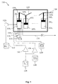
- Figure 1 is a schematic representation of a first example of an engine according to the invention.
- the engine 100 as represented by Figure 1 comprises, in a similar way to thermal engines currently known, a plurality of cylinders 102 1 , 102 2 ,..., 102 n .
- Each cylinder 102 comprises a piston, respectively reference104 1 , 104 2 ,..., 104 n , mobile in translation and defining in each cylinder a combustion chamber 106 1 , 106 2 ,..., 106 n .
- Each piston 104 is pushed in translation by the combustion in the combustion chamber, of a fuel product, allowing the rotation of a transmission shaft 108, as known in current thermal engines.
- the engine 100 comprises, for each cylinder 102 and for each combustion cycle:
- the engine 100 also comprises a corona effect tube 122, located at the outlet of a reservoir of O 2 124, allowing generating a gas flow constituted by pure O 3 or by a mixture of O 3 and O 2 , from O 2 provided by the reservoir 124.
- the gas flow obtained downstream from the corona effect tube 124 (and constituted by pure O 3 or a mixture of O 3 and O 2 ) feeds the module 114 i to regulate the quantity of oxygen, and then its injection into the combustion chamber 106 i .
- the engine 100 also comprises a corona effect tube 126, located at the outlet of a reservoir of CO 2 128, allowing generating a gas flow composed by pure CO 3 or a mixture of CO 3 and CO 2 , from a part of CO 2 provided by the reservoir 128 and from the O 2 provided by the reservoir 124.
- the gas flow obtained downstream from the corona effect tube 126 feeds the module 116 i to regulate the quantity of CO 3 and CO 2 , followed by its injection into the combustion chamber 106 i .
- Combustion of the mixture formed by the load of materials is activated by the combustion chamber 106 or by pressure applied by the piston or by a spark plug (not shown), producing an electric spark in the combustion chamber.
- the combustion gas obtained from the complete combustion of the load of hydrocarbon materials with oxygen entering the combustion chamber 106 is evacuated by an evacuation tube/conduit 130.
- the combustion gas GC is mainly constituted by CO 2 .
- the combustion gas GC includes residual compounds of O 2 , e.g. in a ratio of 1 or 2% of combustion gas, excessively admitted in the combustion chamber 106 to assure complete combustion of the load of hydrocarbon materials HC in the combustion chamber 106.
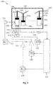
- Figure 2 is the schematic representation of a second embodiment of an engine according to the invention.
- the engine 200 as represented by Figure 2 resumes all the elements and configuration of engine 100 of Figure 1 .
- the engine 200 comprises a treatment module 202 of the combustion gas GC installed in the extraction conduit 130 for combustion gases.
- the treatment module comprises a thermal exchanger (not shown) performing a thermal exchange between the combustion gas GC to take the combustion gas GC to a temperature lower than 100 °C so to condensate H 2 O steam contained in the combustion gas GC. Therefore, the steam found in the combustion gas GC is isolated and feeds the water reservoir 120 to be re-used in the next combustion cycle.
- the combustion gas GC includes residual O 2
- the latter one which is not condensable at the condensation temperature of CO 2
- the combustion gas GC only contains CO 2 feeding the reservoir 128 of CO 2 to be re-used in the next combustion cycle.
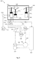
- Figure 3 is a schematic representation of a system for producing energy from hydrocarbon materials according to the invention, by operating the engine of Figure 2 .
- the system 300 for producing energy of Figure 3 comprises the thermal engine 200 of Figure 2 .
- the system 300 comprises a microalgae reactor 302, receiving, through a conduit 304, a part of CO 2 extracted from the combustion gas GC by means of the module 202. Said microalgae reactor 302 produces O 2 by photosynthesis. A conduit 306 captures O 2 produced by the microalgae reactor 302 for feeding the reservoir of O 2 124 for use in a next combustion cycle.
- the invention allows to produce mechanical energy by rotating the shaft 108.
- Said mechanical energy can, for instance, be used to move a vehicle on the ground, in the air or water, such as a boat.
- the thermal engine can be, as a non-limitative example, a diesel engine fed by a petroleum derivative such as heavy fuel oil.
- Mechanical energy can also be used to generate electric energy, e.g. with an electric generator moved by an engine and/or gas turbine and/or liquid hydrocarbons and in combination with a steam turbine alternator.
- modules 110, 114, 116 and 118 can be configured to introduce in the combustion chamber 106, respectively, a predetermined quantity of hydrocarbon materials HC, oxygen in the form of pure O 3 or mixed with O 2 , CO 2 /CO 3 and liquid water, said quantities being determined in accordance to, on one hand the quantity of carbon C and hydrogen H molecules present in the load of hydrocarbon materials admitted into the combustion chamber, so that the load of hydrocarbon materials suffers a complete combustion, i. e. a complete oxidization, and, on the other hand, the size of the cylinder 102 and piston 104 and the desired power at the engine output.
- Each one of the modules 110, 114-118 can be an electronic module controlled by computer.
- each combustion element is separately admitted into the combustion chamber 106. Consequently, it is also possible to mix at least two elements of combustion before admission into the combustion chamber 106 and submit them to thermal and/or mechanical treatment, e.g. compression.
- each combustion element can suffer thermal treatment or compression before being admitted into the combustion chamber.
- the corona effect tube 126 is optional and the oxidizing gas may not contain CO 3 .
- one single corona effect tube can be used instead of tubes 122 and 126.
- the O 2 provided by the reservoir 124 is mixed with the CO 2 provided by the reservoir 128, after the gaseous mixture O 2 +CO 2 is transported by one single corona effect tube.
- thermodynamic yield of an explosion engine with controlled ignition or compression Otto or Diesel is relative to the combustion yield and the transfer from thermal energy to mechanical energy.
- the present invention optimizes combustion yield and, consequently to reduce fuel consumption, for identical energetic product.
- Combustion at "atmospheric" air depends on atmospheric (humidity) and geographic factors (altitude, oxygen-poor air).
- the quantity of oxidizing air is constant and must be oversized to offer the best combustion.
- the quantity of interactive oxygen in air is not higher than 65% of 21% of oxygen existent in the air, at sea level.
- the volume of combustion air interacts with the combustion providing active oxygen, but, on the other hand, increasing the volume of neutral gas (nitrogen), which acts in the opposite direction reducing the combustion zones since it takes space.
- trioxygen molecule can be produced on the site of its use with several possibilities of quantitative and qualitative regulation.
- the trioxygen molecule is unstable and it immediately interacts with its medium, provided that it contains "catalyst" organic materials or that its electric polarity (negative/positive) is opposed to that applied to the ozone.
- the binding of the third oxygen atom and the CO 2 molecule is very unstable. Any proximity with an organic material causes the catalytic reaction of transferring said atom to the organic material; the capture of said oxygen atom, actives the destabilization of the catalyst molecule. Said partial oxidization makes the compounds of the organic molecule more oxidative and more flammable.
- the gaseous oxidizing mixture (O 2 /O 3 + CO 2 /CO 3 ) interacts directly with the fuel.
- Another advantage of the process according to the invention is that the injection of water into the combustion chamber with the oxidizing gaseous mixture favors the distribution of the fuel front flame.
- highly exothermic medium and under temperatures above 1000 °C, CO 2 /CO 3 and H 2 O also interact directly with the fuel by means of a "redox" reaction, which helps distribute and speed up combustion.
- Another advantage of the process according to the invention is that the mixture of CO 2 /oxygen does not generate pollution by nitrogen oxide, since nitrogen molecules are not present in the combustion.
- the fuel is hexadecane, of formula C 16 H 34 , the average density of this fuel is ⁇ 1.
- This state of fact provides energy from a better expansion of the combustion gas.
- CO 2 substitutes nitrogen as ballast gas for thermal gaseous expansion that supplies mechanical work pushing the piston.
- CO 2 has a dilatation coefficient 30% higher than air, thus requiring 23% less of the thermal capacity (heat sensitive).
- said 18 Nm 3 of ballast gas represent 48.021 m 3 for a thermal capacity of 9.283 kWh.
- 1 kg of hexadecane has a lower heating power (PCI) of 11.48 kWh, thus representing combustion yield of 80.86%.
- 1 kg of hexadecane contains 70.66 moles of carbon (see table).
- the minimum CO 2 (to justify an ideal Boudouard reaction homogenizing the combustion) is 70.66 moles of CO 2 , i. e. at least 1.6 Nm 3 of CO 2 (approximately) and maximum of 27 m 3 of CO 2 to exploit 95% of the lower heating power (PCI) of 1 kg of hexadecane: the value for a given engine depends on the type of engine, i. e. the engine cubic capacity, piston course , etc., this value being between these two numbers.
- PCI lower heating power
- a small part of the CO 2 ballast may be substituted by "liquid" water injected at the same time as O 2 and CO 2 of the gaseous oxidizing mixture.
- the process according to the invention reduces the wear of the equipment, maintenance; the whole combustion gas produced is recyclable:
Abstract
- trioxygen (O3); and
- carbon dioxide (CO2) and/or carbon trioxide (CO3).
Description
- The invention refers to a combustion process for hydrocarbon materials in a thermal engine. The invention also refers to a thermal engine implementing and operating said process and system for producing energy from hydrocarbon materials comprising such engine.
- The field of invention is the field of treatment of solid, liquid and/or gaseous hydrocarbon materials, particularly diesel. The invention specifically relates to diesel combustion and generally to hydrocarbon materials in a thermal engine.
- The large majority of the systems of the state of the art performs combustion of said hydrocarbon materials with atmospheric air as oxidizing agent.
- We know that atmospheric air is constituted by 21% oxygen and 78% nitrogen, the balance being rare gases, and only oxygen (O2) is the reactive element of combustion. Nitrogen is a neutral gas, which serves as ballast gas fluid, a thermal fluid and/or work volume expansion in current systems. Said systems are dedicated to the production of thermal energy (boiler shells, etc.) or to a conversion into mechanical energy (thermal engines, turbines, etc.).
- To perform a complete combustion with atmospheric air, the oxidizing agent should be supplied in excess relative to the quantity of reactive oxygen. This equation results in the generation of disproportionate combustion gas volumes over the gases effectively produced by complete combustion. Further, considerable combustion gas volumes generate large inconveniences, considerable atmospheric pollution and effects (heat, organic pollutants, CO2, various oxides, aerosols, etc.) which neutralization is extremely difficult.
- On the other hand, said large volumes of combustion gases become extremely costly means to be implemented to neutralize the generated pollution, especially the capture of CO2, which is one of the main causes of global warming.
- These excessive oxidizing agents also reduce the transffer efficiency of energy of fuel energy to the system, and they usually do not perform complete combustion.
- On the other hand, incomplete combustion of hydrocarbon materials in the current systems causes dirt deposition of non-burnt material, thus reducing yield of the current systems over time.
- The sum of these inconveniences reduces the thermodynamic yield of current thermal engines, rarely surpassing 50% of the heating power of the fuel used, thus meaning waste of more than half of the available energy. Furthermore, a large part of the thermal energy is dissipated by the cooling systems of the engines and exhaust gases. Usually, the "global" yield of thermal engines is lower than 45% of the Lower Heating Power (PCI) of the fuel used.
- Other processes promote a combustion of hydrocarbon materials with pure or eventually mixed dioxygen with a neutral gas such as CO2, e.g. like the process as disclosed by the document
EP 2,383,450 A1 . These proceedings enable to increase yield, reduce the quantity of pollutant particles and facilitate the capture of CO2 from the combustion gas generated by the combustion. - However, it is still possible to increase combustion yield and improve combustion conditions to achieve a more respectful way of combustion, particularly the thermal engine wherein the combustion is performed.
- One of the objects of the invention is to provide a combustion process of hydrocarbon materials in a thermal engine, so to allow for a better yield.
- Another object of the present invention is to provide a combustion process of hydrocarbon materials in a thermal engine, which is more respectful than the thermal engine of the current processes.
- The invention enables to reach at least one of the objects as already explained, by means of a combustion process of solid, liquid or gaseous hydrocarbon materials in a thermal engine comprising at least one combustion chamber, said process comprising at least one interaction of the following steps constituting a combustion cycle:
- introduction in said combustion chamber of a load of hydrocarbon materials and a oxidizing gaseous mixture; and
- triggering of combustion of said load of hydrocarbon materials with said oxidizing gaseous mixture;
- trioxygen (O3); and
- carbon dioxide (CO2) and/or carbon trioxide (CO3).
- As "hydrocarbon materials", we understand petroleum, petroleum derivatives, natural and synthetic petroleum gases, coals and/or biomass, as well as all residues containing carbon and/or hydrocarbon, and synthesis gases from decomposition and gasification of said hydrocarbon materials.
- As oxygen, we understand the oxygen atom (O) which, in current formulations, composes the dioxygen molecule (O2) and the trioxygen molecule (O3), usually called "ozone".
- As "thermal engine", we understand every device performing the combustion of hydrocarbon materials and producing mechanical or electric energy.
- The process of the invention provides a combustion of hydrocarbon materials with an oxidizing gaseous mixture comprising trioxygen (O3) and more particularly negative trioxygen (O3 -).
- The use of trioxygen in the oxidizing gas allows for a better use of each oxygen (O) element and consequently a more complete combustion of hydrocarbon material.
- In fact, as will be disclosed below, the use of trioxygen increases the flammability of hydrocarbon materials by destabilizing the cohesion of their molecules and by speeding up the oxidization of the atoms in their compositions.
- Furthermore, due to the increase in the flammability of the hydrocarbon material by using trioxygen, the combustion of hydrocarbon material is facilitated in terms of temperature and/or pressure, preserving the thermal engine or means operating combustion.
- According to a first embodiment of the process of the invention, the oxidizing gas can solely comprise trioxygen (O3) and carbon dioxide (CO2) and/or carbon trioxide (CO3).
- According to a second embodiment of the process of the invention, the oxidizing gas can also comprise dioxygen (O2).
- Whichever is the embodiment of the process of the invention, trioxygen is dosed for each atom of fuel organic material (C and H) to have the number of oxygen (O) atoms as required for a stoichiometric combustion. Trioxygen present in the oxidizing gas (alone or mixed with dioxygen O2), thermo-chemically interacts with fuel organic materials of multiple form:
- Trioxygen reacts firstly with CO2 in the oxidizing gaseous mixture according to the reaction:
CO2 + O3 ⇄ CO3 + O2 (1)
- Subsequently, trioxygen reacts with the organic materials, which act with catalysts according to the reaction:
O3 + catalyst → catalyst + O catalyst + O2 (2)
- Said interactive bonds are unstable and kept in the order of milliseconds during combustion.
- If the oxidizing gas comprises carbon trioxide (CO3), generated by the reaction (1), the latter instantaneously loses (during the combustion) its third O atom in the form of negative ion (O-), which is also immediately captured by a hydrocarbon fuel molecule. The same happens with trioxygen (O3), from which the surplus oxygen atom is extracted and immediately fixed by an organic catalyst (C or H) of the hydrocarbon molecule, thus creating a free pathway for its parent molecule of O2.
- Said instantaneous and simultaneous interactions increase the flammability of catalyst fuels by destabilizing the cohesion of their molecules and speeding up the oxidization of atoms of their composition.
- The integrity of oxygen available is the heart and the reaction agents. The combustion is complete, with maximum yield with the right measurement of oxygen.
- With the process according to the invention, the lower flammability limit is optimized by factor 5 (five) and the speed of deflagration is doubled relative to atmospheric combustion. Oxidizing conditions make flammability conditions become instantaneous, as well as the thermal generation, thermal transmission and the expansion of the gas volume.
- Providing for a complete combustion of hydrocarbon materials, thermal yield as obtained from the process according to the invention is better than that of the processes and/or engines of the state of the art. Furthermore, the thermal engine is not subject to the dirt deposition of non-burnt material, thus considerably increasing the working life of the system in comparison with the processes of the state of the art.
- The combustion gas, as a result of the combustion, is composed only by CO2 and H2O, with eventual residual O2 molecules. The CO2 is the complete combustion carbon molecule, stable at high temperatures, above 800 °C. H2O is the molecule resulting from the complete combustion of hydrogen from the molecular composition of the hydrocarbon material, said H2O is easily recoverable by condensation, even at atmospheric pressure and temperature. Said two molecules are recyclable and allow recovering most of the dissipated energy of the combustion and reduce the ecological impact on the environment, thus eliminating gaseous pollutants, notably nitrogen oxides, which cannot exist in the absence of nitrogen.
- On the other hand, the oxidizing gas has constant characteristics for any geographic or atmospheric variations (air humidity and altitude). Therefore, quantities can be precise and constant under any circumstances, so to provide for linear and permanently regulated combustion.
- According to the invention, the load of hydrocarbon materials as required for the combustion can be mixed with at least one component of the oxidizing gas before being introduced into the combustion chamber, e.g. with CO2 and/or CO3, or even with pure O3 or eventually with O2.
- The oxidizing gas can be injected in the combustion chamber before, after or simultaneously with the introduction of the load of hydrocarbon material into the combustion chamber.
- CO2 and/or CO3 and pure O3 or eventually mixed with O2 can be separately injected in the combustion chamber, or all of them can be mixed together before the injection in the combustion chamber.
- In the process according to the invention, the combustion can be performed with:
- applying a pressure in the combustion chamber; and/or
- supplying electrical energy to said combustion chamber;
- The process according to the invention can also comprise the injection of a quantity of liquid water in the combustion chamber before, after or simultaneously with the oxidizing gas. Therefore, up to 20% of water relative to the oxidizing gas and preferably between 5% and 20% of water relative to the oxidizing gas can be introduced into the combustion chamber as a function of the thermal regulation as scheduled or desired and the water expansion capacity into steam, which will replace its equivalent into CO2 and/or CO3.
- The injection of water allows regulating the combustion temperature, since it absorbs a large quantity of energy from combustion into latent heat, thus reducing thermal losses caused by the dissipation in the cooling and combustion exhaust gas circuits. The injected liquid water represents a negligible volume ratio with the oxidizing gaseous mixture of less than 20% as a function of the size of the thermal system at issue. Once amidst the combustion medium, said water evaporates into overheated steam. The expansion of the volume of liquid water as converted into steam is more than 10 times to hundreds of times the value introduced as a function of the dynamic pressure as impinged.
- Therefore, latent heat of evaporation is completely and immediately transformed into useful thermodynamic energy, instead of having a considerable part of it dissipated by the cooling and combustion gas exhaust circuits. The portion of injected water is limited by lowering the temperature caused by its evaporation and which should not be lower than the optimal operating temperature of the thermal system at issue. The volume of the portion of evaporated water replaces the equivalent volume of CO2/CO3.
- The oxidizing gas can comprise between 15 and 25% of oxygen, in the form of pure O3 or in the form of a mixture of O3 and O2, and between 85 and 75% of CO2 and/or CO3.
- More particularly, the oxidizing gas can comprise between 18 and 22%, preferably 21% of oxygen in the form of pure O3 or in the form of a mixture of O3 and O2, and between 82 and 78%, preferably 79%, of CO2 and/or CO3.
- The oxidizing gas advantageously comprises, for a mole of carbon of hydrocarbon material, at least one mole of CO2 and/or CO3, and a maximum of 17 moles of CO2 and/or CO3.
- The oxidizing gaseous mixture advantageously comprises, for one carbon atom of the hydrocarbon material, at least the equivalent to two oxygen atoms and a maximum of the equivalent to 102% of oxygen, in the form of pure O3 or in the form of a mixture of O3 and O2.
- The oxidizing gas can advantageously comprise for a hydrogen (H) atom in the hydrocarbon material, at least one oxygen atom in the form of pure O3 or in the form of a mixture of O3 and O2, and a maximum of the equivalent to 102% of oxygen in the form of pure O3 or in the form of a gas mixture of O3 and O2.
- When the oxidizing gas comprises pure trioxygen, the latter be obtained from a pure O3 reservoir/tank. When the oxidizing gas comprises trioxygen mixed with dioxygen, the mixture can be obtained either from a reservoir/tank containing a mixture of O3 and O2, or from a reservoir containing pure O3 and a reservoir containing pure O2.
- Alternatively, the process according to the invention can also comprise a step of generation of trioxide from oxygen molecules, more particularly from dioxygen molecules (O2), e. g. by the "CORONA" effect applied to the oxygen molecules , more particularly to dioxygen molecules.
- For that purpose, the process according to the invention can implement a production mean of trioxygen (O3).
- Trioxide generating means can comprise a "CORONA" effect device, installed e.g. on a conduit in which oxygen (O2) flows, such as the injection tube of dioxygen O2 into the combustion chamber, to induce electric conversion discharges according to the formula:
O2 + hv → O2 * (3Σ u -)
(170 to 210 nm)
O2* + O2 → O3 + O, O + O2 → O3
- The ratio of oxygen to be converted is defined by the intensity of the induced Corona effect, and the portion of O3 can vary between 10 and 100% of the oxidizing oxygen as included in the gaseous oxidizing mixture.
- Furthermore, the process according to the invention can comprise a step of generation of carbon trioxide CO3 from CO or CO2 molecules, and preferably from CO2 molecules, e.g. by means of the "CORONA" effect applied to the CO2 molecules in the presence of O3/O2.
- According to a preferred embodiment, the oxidizing gas is obtained from a gaseous mixture of O2 and CO2, to which Corona effect is applied to generate O3 and CO3 molecules, the oxidizing gas therefore, obtained comprises:
- O3; and
- CO2 or CO3 or a mixture of CO2 and CO3; and
- As disclosed above, the combustion gas obtained after the combustion essentially comprises CO2 and H2Osteam.
- The process according to the invention can also comprise a recovery of CO2 included in the combustion gas, by cooling said combustion gas.
- When the combustion gas comprises H2O molecules, steam can be previously removed from the combustion gas by condensation, and then, CO2 and the latent heat from condensation can be recovered.
- Advantageously, CO2 can be condensed by any/all process known by the expert in the art. Therefore, all non-condensable material originated from the fuel and/or from the oxidizing gaseous mixture (metals, metalloids, sulfur, oxygen) are isolated from CO2, which is pure in liquid stage, and can be stored and recycled in the process. CO2 can be evaporated during the cooling process of the combustion gas before being re-injected into the combustion chamber for a new cycle.
- Thermal energy (thermal capacity/sensitive and latent heat) of the combustion gas can also be recovered, by means of heat exchange with a thermal fluid with one or more heat exchangers, e. g. aiming to produce electricity with a turbine.
- A part of CO2 recovered from the combustion gas of a combustion cycle can be advantageously re-used in the oxidizing gas and/or to generate carbon trioxide as disclosed above, to perform a new combustion cycle.
- A part of CO2 recovered from the combustion gas can be re-used in a microalgae culture, e. g. in a microalgae reactor, wherein the microalgae culture provides O2 by means of photosynthesis.
- At least a part of O2 provided by microalgae can be used in the oxidizing gas and/or to generate trioxygen as disclosed above, for a new combustion cycle.
- According to another aspect of the invention, it is provided a thermal engine performing a combustion of hydrocarbon materials, and particularly organized means to operate all the steps of the combustion process according to the invention. The thermal engine according to the invention can comprise trioxygen generating means from oxygen atoms, more particularly from a gaseous flow of O2.
- Said carbon trioxide generating means can comprise means applying Corona effect with oxygen atoms, more particularly with a gaseous flow of O2, such as e.g. a Corona effect tube disposed on a duct in which O2 flows.
- The thermal engine according to the invention can also comprise means to generate carbon trioxide from CO molecules or preferably from CO2 molecules.
- Said carbon trioxide generating means can comprise means to apply Corona effect on CO molecules or preferably on CO2 molecules, such as e.g. a Corona effect tube disposed on the duct in which CO2 flows in the presence of O3/O2.
- The thermal engine according to the invention can further comprise at least one adjustment module for the:
- quantity of CO2 and/or CO3; and/or
- quantity of oxygen in the form of pure O3 or a mixture of O3 and O2;
- The thermal engine can also comprise at least one adjustment module of the quantity of liquid water introduced into the combustion chamber and eventually an adjustment module of the quantity of hydrocarbon materials for each combustion cycle.
- According to another aspect of the invention, it is provided a vehicle with a thermal engine according to the invention to move the vehicle. Said vehicle can be e.g. a boat or a train.
- According to another aspect of the invention, it is provided a system for producing mechanical or electrical energy from hydrocarbon materials, comprising:
- a thermal engine according to the invention, supplying a combustion gas comprising CO2; and
- at least one microalgae reactor producing O2 by photosynthesis;
- at least one means for feeding said reactor with at least a part of CO2 present in said combustion gas; and
- at least one means for recovering at least a part of said O2 produced by said microalgae reactor and reusing said recovered O2 to generate trioxygen.
- Other advantages and characteristics will emerge after examining the detailed description of non-limitative embodiments and the attached drawings, wherein:
-
Figure 1 is a schematic representation of a first embodiment of a thermal engine according to the invention; -
Figure 2 is a schematic representation of a second embodiment of a thermal engine according to the invention; and -
Figure 3 is a schematic representation of a system to produce energy from hydrocarbon materials according to the invention, by embodying and operating the engine ofFigure 2 . - It is understood that the embodiments described below will not be limitative. We can notably imagine variations of the invention comprising only a selection of the characteristics described below, isolated from the other characteristics as described, if this selection of characteristics is sufficient to confer a technical advantage or to show the difference between the present invention over the state of previous art. This selection comprises at least one preferable functional characteristic with no structural details, or only with a part of the structural details if this part is sufficient only to confer a technical advantage or to distinguish the invention unique enough over the state of the prior art.
- In the drawings, the elements common to several figures keep the same reference.
-
Figure 1 is a schematic representation of a first example of an engine according to the invention. - The
engine 100 as represented byFigure 1 comprises, in a similar way to thermal engines currently known, a plurality ofcylinders cylinder 102 comprises a piston, respectively reference1041, 1042,..., 104n, mobile in translation and defining in each cylinder acombustion chamber piston 104 is pushed in translation by the combustion in the combustion chamber, of a fuel product, allowing the rotation of atransmission shaft 108, as known in current thermal engines. - The
engine 100 comprises, for eachcylinder 102 and for each combustion cycle: - a first module 110i, adjusting the quantity of hydrocarbon materials HC introduced into the
combustion chamber 106, from areservoir 112 of hydrocarbon materials; - a
second module 114i, dosing the quantity of oxygen introduced into thecombustion chamber 106, in the form of pure O3 or a mixture of O3 and O2; - a
third module 116i, dosing the quantity of pure CO2, pure CO3 or also CO2 mixed with CO3, introduced in thecombustion chamber 106; - a forth module 118i, dosing the quantity of liquid H2O as introduced into the
combustion chamber 106 from a H2O reservoir 120. - The
engine 100 also comprises acorona effect tube 122, located at the outlet of a reservoir ofO 2 124, allowing generating a gas flow constituted by pure O3 or by a mixture of O3 and O2, from O2 provided by thereservoir 124. The gas flow obtained downstream from the corona effect tube 124 (and constituted by pure O3 or a mixture of O3 and O2) feeds themodule 114i to regulate the quantity of oxygen, and then its injection into thecombustion chamber 106i. - The
engine 100 also comprises acorona effect tube 126, located at the outlet of a reservoir ofCO 2 128, allowing generating a gas flow composed by pure CO3 or a mixture of CO3 and CO2, from a part of CO2 provided by thereservoir 128 and from the O2 provided by thereservoir 124. The gas flow obtained downstream from thecorona effect tube 126 feeds themodule 116i to regulate the quantity of CO3 and CO2, followed by its injection into thecombustion chamber 106i. - Combustion of the mixture formed by the load of materials (hydrocarbons + oxidizing gas) is activated by the
combustion chamber 106 or by pressure applied by the piston or by a spark plug (not shown), producing an electric spark in the combustion chamber. - The combustion gas obtained from the complete combustion of the load of hydrocarbon materials with oxygen entering the
combustion chamber 106 is evacuated by an evacuation tube/conduit 130. The combustion gas GC is mainly constituted by CO2. On one hand, the CO2 admitted into thecombustion chamber 106 through themodule 116 and, on the other hand, CO2 formed by the oxidization of carbon elements C present in hydrocarbon compounds by the O3 compounds (and possibly O2), and H2O, on one side H2O eventually admitted in thecombustion chamber 106 by the module 118 and, on the other side, H2O formed by the oxidization of the di-hydrogen elements H2 present in the hydrocarbon compounds. - It is possible that the combustion gas GC includes residual compounds of O2, e.g. in a ratio of 1 or 2% of combustion gas, excessively admitted in the
combustion chamber 106 to assure complete combustion of the load of hydrocarbon materials HC in thecombustion chamber 106. -
Figure 2 is the schematic representation of a second embodiment of an engine according to the invention. - The
engine 200 as represented byFigure 2 resumes all the elements and configuration ofengine 100 ofFigure 1 . - Besides the
engine 100 ofFigure 1 , theengine 200 comprises atreatment module 202 of the combustion gas GC installed in theextraction conduit 130 for combustion gases. - The treatment module comprises a thermal exchanger (not shown) performing a thermal exchange between the combustion gas GC to take the combustion gas GC to a temperature lower than 100 °C so to condensate H2O steam contained in the combustion gas GC. Therefore, the steam found in the combustion gas GC is isolated and feeds the
water reservoir 120 to be re-used in the next combustion cycle. - When the combustion gas GC includes residual O2, the latter one, which is not condensable at the condensation temperature of CO2, is isolated by means of CO2 condensation and feeds the reservoir of
O 2 124 to be re-used in the next combustion cycle. - Finally, after separating steam from O2, the combustion gas GC only contains CO2 feeding the
reservoir 128 of CO2 to be re-used in the next combustion cycle. -
Figure 3 is a schematic representation of a system for producing energy from hydrocarbon materials according to the invention, by operating the engine ofFigure 2 . - The
system 300 for producing energy ofFigure 3 comprises thethermal engine 200 ofFigure 2 . - Besides the thermal engine of
Figure 2 , thesystem 300 comprises amicroalgae reactor 302, receiving, through aconduit 304, a part of CO2 extracted from the combustion gas GC by means of themodule 202. Saidmicroalgae reactor 302 produces O2 by photosynthesis. Aconduit 306 captures O2 produced by themicroalgae reactor 302 for feeding the reservoir ofO 2 124 for use in a next combustion cycle. - In all the examples disclosed, the invention allows to produce mechanical energy by rotating the
shaft 108. - Said mechanical energy can, for instance, be used to move a vehicle on the ground, in the air or water, such as a boat. In this case, the thermal engine can be, as a non-limitative example, a diesel engine fed by a petroleum derivative such as heavy fuel oil.
- Mechanical energy can also be used to generate electric energy, e.g. with an electric generator moved by an engine and/or gas turbine and/or liquid hydrocarbons and in combination with a steam turbine alternator.
- In all the examples disclosed,
modules combustion chamber 106, respectively, a predetermined quantity of hydrocarbon materials HC, oxygen in the form of pure O3 or mixed with O2, CO2/CO3 and liquid water, said quantities being determined in accordance to, on one hand the quantity of carbon C and hydrogen H molecules present in the load of hydrocarbon materials admitted into the combustion chamber, so that the load of hydrocarbon materials suffers a complete combustion, i. e. a complete oxidization, and, on the other hand, the size of thecylinder 102 andpiston 104 and the desired power at the engine output. - Each one of the
modules 110, 114-118 can be an electronic module controlled by computer. - In all the examples disclosed, each combustion element is separately admitted into the
combustion chamber 106. Consequently, it is also possible to mix at least two elements of combustion before admission into thecombustion chamber 106 and submit them to thermal and/or mechanical treatment, e.g. compression. - In all disclosed cases, each combustion element can suffer thermal treatment or compression before being admitted into the combustion chamber.
- In the examples described, the
corona effect tube 126 is optional and the oxidizing gas may not contain CO3. - Alternatively, one single corona effect tube can be used instead of
tubes reservoir 124 is mixed with the CO2 provided by thereservoir 128, after the gaseous mixture O2+CO2 is transported by one single corona effect tube. - We now describe a combustion of hydrocarbon materials according to the invention, when the hydrocarbon material is solely constituted of hexadecane with the formula C16H34, in comparison with a combustion under atmospheric air.
- The table below shows the characteristics of hexadecane C16H34:
Characteristics of hexadecane molecule (Cethane) C16H34 (ratio per kg) molar mass = 226.44 g/mol =4.42 moles/kg PCS oxygen (O2) useful for complete combustion (stoichiometric) C16 C=70.66 moles/kg CO2 : 394 kJ/mol oxygen O2 =70.66 moles/kg 
H34 H2=75.075 moles/kg H2O : 242 kJ/mol oxygen O2 =37.54 moles/kg 
Total = 46 007.37 kJ/kg Total =108.20 moles/kg =12.78 kWh/kg Oxygen (O2) p/ kg C16H34 molar mass: =32.00 g/mol Total =3.46 kg/kg =2.425 Nm3/kg - Wherein it describes that:
- 1 kg of hexadecane has a higher heating value (PCS) of 12.78 kWh and a lower heating power (PCI) of 11.48 kWh ≈ -9%;
- The complete oxidization of 1 mole of carbon in 1 mole of CO2 generates an exothermic reaction of 394 kilojoules, while the incomplete oxidization of 1 mole of carbon into 1 mole of CO only generates an exothermic reaction of 111 kilojoules, i. e. 3.55 times less;
- Each particle is carbon and each gram of carbon can generate 32.83 kilojoules of thermal energy with 1 mole of carbon = 12 g.
- The "thermodynamic" yield of an explosion engine, with controlled ignition or compression Otto or Diesel is relative to the combustion yield and the transfer from thermal energy to mechanical energy.
- The present invention optimizes combustion yield and, consequently to reduce fuel consumption, for identical energetic product.
- Combustion at "atmospheric" air depends on atmospheric (humidity) and geographic factors (altitude, oxygen-poor air). In Diesel engines, at constant volumes, the quantity of oxidizing air is constant and must be oversized to offer the best combustion. The quantity of interactive oxygen in air is not higher than 65% of 21% of oxygen existent in the air, at sea level. To reach the oxygen of the stoichiometric combustion, we need to double the volume of oxidizing air. The volume of combustion air interacts with the combustion providing active oxygen, but, on the other hand, increasing the volume of neutral gas (nitrogen), which acts in the opposite direction reducing the combustion zones since it takes space.
- One of the advantages of the process, according to the invention is that the trioxygen molecule can be produced on the site of its use with several possibilities of quantitative and qualitative regulation.
- Another advantage of the process, according to the invention is that the trioxygen molecule is unstable and it immediately interacts with its medium, provided that it contains "catalyst" organic materials or that its electric polarity (negative/positive) is opposed to that applied to the ozone. The prime interaction between trioxygen with the carbon dioxide molecule in the gaseous oxidizing mixture, before its injection in the combustion chamber, generates carbon trioxide (CO3). The binding of the third oxygen atom and the CO2 molecule is very unstable. Any proximity with an organic material causes the catalytic reaction of transferring said atom to the organic material; the capture of said oxygen atom, actives the destabilization of the catalyst molecule. Said partial oxidization makes the compounds of the organic molecule more oxidative and more flammable.
- The gaseous oxidizing mixture (O2/O3 + CO2/CO3) interacts directly with the fuel.
- The instability of the trioxygen bindings and their immediate capture by the organic catalysts create an "autogenous" pre-combustion of the fuel materials, oxygen then interacts directly with fuel under more favorable conditions than the usual combustion/oxidization, without the fact that being mixed with CO2/CO3 hampers this reaction, which is exothermal.
- Another advantage of the process according to the invention is that the injection of water into the combustion chamber with the oxidizing gaseous mixture favors the distribution of the fuel front flame. In that highly exothermic medium and under temperatures above 1000 °C, CO2/CO3 and H2O also interact directly with the fuel by means of a "redox" reaction, which helps distribute and speed up combustion.
- ∘ In atmospheric combustion, numerous carbon particles are not burned, thus hydrocarbon molecules, which have not been oxidized by the mixture of combustion air.
- ∘ In the process, according to the invention, atomic and molecular oxygen reacts directly with the fuel and decomposes the hydrocarbon molecule oxidizing C and H. At the same time, a "redox" reaction is activated by CO2 and H2O of the mixture, which also react with C and H of the decomposed molecules of the following redox reactions:
- ▪ C + CO2 ⇄ 2CO + 172 kJ/mol
- ▪ H2 + CO2 ⇄ H2O+CO + 41 kJ/mol
- These reactions are endothermal; they take part in the regulation of the temperature of the medium and reduce thermal dissipation. The reaction (C + CO2 ⇄ 2CO) gasifies carbon structures and amorphous carbon elements (particles, soot) which would not be directly oxidized by O2. Therefore, they are converted into gaseous molecules (CO) that are more reactive to complete oxidation (eminently more flammable because of their gaseous state, which causes CO molecules to have a better distribution in front of the flame(s) of the thermal system and by of the thermochemical conditions of the medium) in the presence of free oxygen:
- • CO + O ⇄ CO2 - 283 kJ/mol
- Therefore, completion of combustion is progressive during the thrust (work) period of the engine pistons, which increases thermodynamic capacity for a same unit of fuel, improves the linear efficiency by distributing thermal effects throughout the course of said piston, and thus reduces wear due to thermal differentials, reducing global thermal dissipation.
- The same thing happens to the H2O molecule that react with CO according to:
- ▪ H2O + CO ⇄ H2 + CO2 - 41 kJ/mol; and
- ▪ H2 + O ⇄ H2O - 242 kJ/mol.
- Therefore, completion of combustion is progressive during the thrust (work) period of the engine pistons, increasing thermodynamic efficiency by homogenization of thermal distributions by these sequences of simultaneous exothermal reactions.
- Another advantage of the process according to the invention is that the mixture of CO2/oxygen does not generate pollution by nitrogen oxide, since nitrogen molecules are not present in the combustion.
- In the present example, the fuel is hexadecane, of formula C16H34, the average density of this fuel is ≤1.
- As disclosed on the table, to perform the stoichiometric combustion of 1 liter of hexadecane, 3.46 kg of oxygen (O2) (2.425 Nm3) are required.
- For atmospheric combustion with 50% efficiency yield with the characteristics of the current processes and engines, one must consider the volume of air as a function of the efficiency coefficient of separation O2 from the nitrogen mixture, approximately 60/65%.
- To reach the combustion yield of said engines, an excess of oxygen of at least 15% is required, i. e.:
- 3.98 kg or 2.79 Nm3 of O2
- Considering an efficiency coefficient of separation of O2 of 65%:
- 2.79 / 65% = 4.29 Nm3 of O2
- Considering a 21% percentage of O2 per m3 of air:
- 20.43 Nm3 of air per liter of hexadecane.
- This combustion has only 50% of efficiency.
- An engine is designed then in function of these parameters. Current engines work with a proportion of 1/5 of oxygen in the oxidizing mixture (the same ratio as in air).
- The process according to the invention only requires an excess of O2 between 2 and 5% for a combustion yield higher than 93%, i. e.:
- 3.57 kg or 2.50 Nm3 of O2.
- Since there is no constraint linked to the separation of the gaseous mixture, oxygen is totally active. Combustion yield is maximized.
- Complete combustion of carbon generates CO2 and 3.6 times more energy than that produced by incomplete combustion in CO:
- C+O = CO 111 kJ/mol
- C+O2 = CO2 394 kJ/mol
- This state of fact provides energy from a better expansion of the combustion gas.
- CO2 substitutes nitrogen as ballast gas for thermal gaseous expansion that supplies mechanical work pushing the piston.
- At 800 °C, CO2 has a dilatation coefficient 30% higher than air, thus requiring 23% less of the thermal capacity (heat sensitive).
- From this, if we compare "atmospheric" values, transposed to O2/CO2, we have:
- 20.43 Nm3 of air per liter of hexadecane less oxidizing oxygen "2.425 Nm3 of O2" (see table) = 18 Nm3 of ballast gas(nitrogen + rare gases):
- At 800 °C, said 18 Nm3 of ballast gas represent 48.021 m3 for a thermal capacity of 9.283 kWh. 1 kg of hexadecane has a lower heating power (PCI) of 11.48 kWh, thus representing combustion yield of 80.86%.
- 18 Nm3 of ballast gas CO2:
- At 800 °C, said 18 Nm3 substituted by CO2 expand into 62.654 m3 for a thermal capacity of 7.174 kWh.
- About 15 m3 of exceeding "work" capacity.
- 1 kg of hexadecane has a lower heating power (PCI) of 11.48 kWh, which leave more than 4 kWh of exceeding thermal energy, i. e.:
- The capacity to generate about 35 m3 of CO2 at 800°C, i. e., cumulated an exceeding total of 50 m3 of CO2 at 800 °C.
- Alternatively:
- 1 kg of hexadecane + 2.425 Nm3 of O2 + 18 Nm3 of CO2 produce two times more work capacity than 1 kg of hexadecane in atmospheric combustion.
- ½ kg of hexadecane + 1.213 Nm3 of O2 + 9 Nm3 of CO2 produce the same work as 1 kg of hexadecane in atmospheric combustion.
- Another example, 1 kg of hexadecane contains 70.66 moles of carbon (see table). The minimum CO2 (to justify an ideal Boudouard reaction homogenizing the combustion) is 70.66 moles of CO2, i. e. at least 1.6 Nm3 of CO2 (approximately) and maximum of 27 m3 of CO2 to exploit 95% of the lower heating power (PCI) of 1 kg of hexadecane: the value for a given engine depends on the type of engine, i. e. the engine cubic capacity, piston course , etc., this value being between these two numbers.
- Additionally, a small part of the CO2 ballast may be substituted by "liquid" water injected at the same time as O2 and CO2 of the gaseous oxidizing mixture.
- This addition may happen in order to:
- regulate the combustion temperature absorbing a large quantity of energy in latent heat to transform it into dynamic energy by volume expansion of steam; and
- homogenize the combustion by the redox reaction which can occur during the change of state (liquid/ steam) if the H2O molecule of steam is near a CO molecule . Said exothermal reaction releases a di-hydrogen (H2) molecule in the medium that will react in any way with the oxygen of said medium, either with a free (O) atom or with an (O) atom of a trioxidized molecule.
- reduce thermal loss by dissipation, latent heat is recovered during steam condensation by the cold heat carrier (liquid and/or gaseous CO2, oxygen, liquid water).
- The process according to the invention reduces the wear of the equipment, maintenance; the whole combustion gas produced is recyclable:
- H2O is condensable into distilled water;
- CO2 is partially recycled for re-use in the process according to the invention; and
- excess CO2 and H2O can be recycled in a microalgae culture plant, which will then produce hydrocarbon materials and oxygen.
- Anyway, the invention is not limited to the examples disclosed above.
Claims (14)
- Combustion process for solid, liquid or gaseous hydrocarbon (HC) raw materials in a thermal engine (100; 200) comprising at least one combustion chamber (106), said process comprising at least one iteration of the following steps constituting a combustion cycle by means of the introduction into said combustion chamber (106), of a load of hydrocarbon materials (HC) and an oxidizing gas, triggering the combustion of said load of hydrocarbon materials with said oxidizing gas; characterized in that said oxidizing gas comprises:- trioxygen (O3); and- carbon dioxide (CO2) and/or carbon trioxide (CO3).
- Process according to claim 1, characterized by the oxidizing gas comprises solely trioxygen (O3) and carbon dioxide (CO2) and/or carbon trioxide (CO3).
- Process according to claim 1, characterized in that the oxidizing gas also comprises dioxygen (O2).
- Process according to any of the preceding claims, characterized in that the load of hydrocarbon (HC) materials is mixed with at least one component of the oxidizing gas before being introduced in the combustion chamber (106).
- Process according to any of the preceding claims, characterized in that the combustion triggering of combustion is carried out by:- applying a pressure in the combustion chamber (106); and/or- supplying electrical energy to said combustion chamber (106).
- Process according to any of the preceding claims, characterized in that the process further comprises an injection of a given quantity of liquid and/or gaseous water (H2O) in the mixture.
- Process according to any of the preceding claims, characterized in that the oxidizing gas comprises between 15 and 25% of oxygen, in the form of pure O3 or in the form of a mixture of O3 and O2, and between 85 and 75% of CO2 and/or CO3.
- Process according to any of the preceding claims, characterized in that the oxidizing gas comprises, for one mole of carbon in the hydrocarbon material, at least one mole of CO2 and/or CO3 and a maximum of 17 moles of CO2 and/or CO3.
- Process according to any of the preceding claims, characterized in that comprises recovering of CO2 present in the combustion gas (GC) obtained after combustion, by means of cooling of said combustion gas (GC), and the use of at least a part of CO2 recovered from the combustion gas (GC), in the oxidizing gas for a new combustion cycle.
- Process according to claim 9, characterized in that comprises using a part of CO2 recovered in the combustion gas (GC) in microalgae culture, said microalgae culture providing O2 by means of photosynthesis, at least a part of said O2 is used to obtain trioxide, containing the oxidizing gas for a new combustion cycle.
- Process according to any of the preceding claims, characterized in that comprises a step of generation of trioxide (O3) and respectively carbon trioxide (CO3), by means of the corona effect applied to the molecules of dioxygen (O2) and respectively to the molecules of carbon dioxide (CO2).
- Thermal engine (100, 200) characterized by carrying out a combustion of hydrocarbon materials according to any of claims 1 to 11.
- Thermal engine (100, 200) according to claim 12, characterized by comprising at least one adjustment module (114, 116) for the:- quantity of CO2 and/or CO3; and/or- quantity of oxygen in the form of pure O3 or in the form of a mixture of O3 and O2;
used in the oxidizing gas. - System (300) for producing energy from hydrocarbon (HC) materials, characterized by comprising:- a thermal engine (100, 200) according to any of claims 12 or 13, providing a combustion gas (GC) comprising CO2; and- at least one microalgae reactor (302) producing O2 by photosynthesis;- at least one means (202, 304) for feeding said reactor (302) with at least a part of CO2 present in said combustion gas (GC); and- at least one means (306) for recovering at least one part of said O2 produced by said microalgae reactor and re-using it to generate a part of the oxidizing gas.
Applications Claiming Priority (2)
| Application Number | Priority Date | Filing Date | Title |
|---|---|---|---|
| FR1362395A FR3014486B1 (en) | 2013-12-11 | 2013-12-11 | METHOD FOR COMBUSTING HYDROCARBON MATERIALS IN A THERMAL MOTOR, THERMAL ENGINE AND ENERGY GENERATION SYSTEM USING SUCH A METHOD |
| PCT/BR2014/000435 WO2015085383A1 (en) | 2013-12-11 | 2014-12-10 | A process of combustion of solid, liquid or gaseous hydrocarbon (hc) raw materials in a heat engine, heat engine and system for producing energy from hydrocarbon (hc) materials |
Publications (3)
| Publication Number | Publication Date |
|---|---|
| EP3081289A1 true EP3081289A1 (en) | 2016-10-19 |
| EP3081289A4 EP3081289A4 (en) | 2017-11-22 |
| EP3081289B1 EP3081289B1 (en) | 2019-06-19 |
Family
ID=50624682
Family Applications (1)
| Application Number | Title | Priority Date | Filing Date |
|---|---|---|---|
| EP14869529.9A Not-in-force EP3081289B1 (en) | 2013-12-11 | 2014-12-10 | A combustion process for solid, liquid or gaseous hydrocarbon (hc) raw materials in a thermal engine, thermal engine and system for producing energy from hydrocarbon (hc) materials |
Country Status (8)
| Country | Link |
|---|---|
| US (1) | US20160327267A1 (en) |
| EP (1) | EP3081289B1 (en) |
| JP (1) | JP6574183B2 (en) |
| BR (1) | BR112016013128B1 (en) |
| ES (1) | ES2755325T3 (en) |
| FR (1) | FR3014486B1 (en) |
| PT (1) | PT3081289T (en) |
| WO (1) | WO2015085383A1 (en) |
Families Citing this family (1)
| Publication number | Priority date | Publication date | Assignee | Title |
|---|---|---|---|---|
| CN113470763B (en) * | 2021-07-14 | 2023-03-14 | 中国航发贵阳发动机设计研究所 | System for measuring and calculating components of thermal dissociation gas generated by combustion of hydrocarbon fuel |
Family Cites Families (17)
| Publication number | Priority date | Publication date | Assignee | Title |
|---|---|---|---|---|
| US4498289A (en) * | 1982-12-27 | 1985-02-12 | Ian Osgerby | Carbon dioxide power cycle |
| DE4215557A1 (en) * | 1992-05-12 | 1993-01-28 | Hilarius Dipl Ing Drzisga | Low-emission IC engine - has cylinder, each with discharge slot and discharge valve, uses oxidation gas of ozone and oxygen |
| JP2004066091A (en) * | 2002-08-06 | 2004-03-04 | Meidensha Corp | Method of treating carbon dioxide-containing gas and equipment therefor |
| US6851413B1 (en) * | 2003-01-10 | 2005-02-08 | Ronnell Company, Inc. | Method and apparatus to increase combustion efficiency and to reduce exhaust gas pollutants from combustion of a fuel |
| JP2004218613A (en) * | 2003-01-17 | 2004-08-05 | Kazuo Motochi | Ozone supply device of internal-combustion engine |
| WO2004067933A2 (en) * | 2003-01-21 | 2004-08-12 | Los Angeles Advisory Services Inc. | Low emission energy source |
| US6990965B2 (en) * | 2003-12-16 | 2006-01-31 | Birasak Varasundharosoth | Combustion-engine air-intake ozone and air ion generator |
| US8136510B2 (en) * | 2005-07-15 | 2012-03-20 | Clack Technologies, Llc | Apparatus for improving efficiency and emissions of combustion |
| US7798133B2 (en) * | 2005-07-15 | 2010-09-21 | Clack Technologies Llc | Apparatus for improving efficiency and emissions of combustion |
| US8485163B2 (en) * | 2005-07-15 | 2013-07-16 | Clack Technologies Llc | Apparatus for improving efficiency and emissions of combustion |
| US8991364B2 (en) * | 2005-07-15 | 2015-03-31 | Clack Technologies Llc | Apparatus for improving efficiency and emissions of combustion |
| JP4692220B2 (en) * | 2005-10-27 | 2011-06-01 | トヨタ自動車株式会社 | Exhaust gas purification device for internal combustion engine |
| CA2828290C (en) * | 2006-09-20 | 2017-08-08 | Imagineering, Inc. | Ignition device, internal combustion engine, ignition plug, plasma apparatus, exhaust gas decomposition apparatus, ozone generation/sterilization/disinfection apparatus, and deodorization apparatus |
| JP4285528B2 (en) * | 2006-11-06 | 2009-06-24 | トヨタ自動車株式会社 | Exhaust gas recirculation system for internal combustion engines |
| JP3151353U (en) * | 2009-04-09 | 2009-06-18 | ポン,ハン−タオ | Complete combustion assist structure for automobiles |
| DE102010018703A1 (en) * | 2010-04-29 | 2011-11-03 | Messer Group Gmbh | Method for operating an internal combustion engine and internal combustion engine |
| JP5480862B2 (en) * | 2011-09-22 | 2014-04-23 | 株式会社日立製作所 | Power conversion system |
-
2013
- 2013-12-11 FR FR1362395A patent/FR3014486B1/en active Active
-
2014
- 2014-12-10 JP JP2016538623A patent/JP6574183B2/en active Active
- 2014-12-10 US US15/103,722 patent/US20160327267A1/en not_active Abandoned
- 2014-12-10 EP EP14869529.9A patent/EP3081289B1/en not_active Not-in-force
- 2014-12-10 ES ES14869529T patent/ES2755325T3/en active Active
- 2014-12-10 PT PT148695299T patent/PT3081289T/en unknown
- 2014-12-10 WO PCT/BR2014/000435 patent/WO2015085383A1/en active Application Filing
- 2014-12-10 BR BR112016013128-2A patent/BR112016013128B1/en active IP Right Grant
Also Published As
| Publication number | Publication date |
|---|---|
| JP6574183B2 (en) | 2019-09-11 |
| BR112016013128A2 (en) | 2017-08-08 |
| FR3014486B1 (en) | 2017-11-17 |
| JP2017508094A (en) | 2017-03-23 |
| WO2015085383A1 (en) | 2015-06-18 |
| FR3014486A1 (en) | 2015-06-12 |
| ES2755325T3 (en) | 2020-04-22 |
| EP3081289B1 (en) | 2019-06-19 |
| EP3081289A4 (en) | 2017-11-22 |
| PT3081289T (en) | 2019-10-08 |
| BR112016013128B1 (en) | 2022-02-08 |
| US20160327267A1 (en) | 2016-11-10 |
Similar Documents
| Publication | Publication Date | Title |
|---|---|---|
| TWI522454B (en) | Thermal and chemical utilisation of carbonaceous substances, in particular for emission-free generation of energy | |
| EP1053394A4 (en) | Method and apparatus for total energy fuel conversion systems | |
| EP3830400B1 (en) | Energy storage with hydrogen | |
| RU2385836C2 (en) | Method of developing hydrogen energy chemical complex and device for its realisation | |
| US20230018213A1 (en) | Emission-free devices and method for performing mechanical work and for generating electrical and thermal energy | |
| De Vries et al. | Use of ammonia for heat, power and propulsion | |
| CN107191288A (en) | Pure oxygen oxygen-enriched combusting primemover system device | |
| EP3081289B1 (en) | A combustion process for solid, liquid or gaseous hydrocarbon (hc) raw materials in a thermal engine, thermal engine and system for producing energy from hydrocarbon (hc) materials | |
| KR102073708B1 (en) | an appropriate rate mixed fuel of fossil fuel and water electrolysis gas to enhance the fuel efficiency | |
| CN102020243A (en) | Method for decomposing water into hydrogen-oxygen mixed gas fuel | |
| EP2325287A1 (en) | Emission-free power plant for the production of mechanical and electrical energy | |
| DK2348254T3 (en) | Refueling system for a mobile machine | |
| CN101705844A (en) | Power generating system of coal-gas turbine without carbon emission and method thereof | |
| JP2010531214A (en) | Gas waste treatment method and system for separately generating H2 and CO | |
| RU2386819C2 (en) | Method of energy conversion with regeneration of energy sources in barchan cyclic process | |
| EP2348253A1 (en) | Emission-free method for accomplishing mechanical work | |
| GB2566460A (en) | A design for an efficient symbiotic energy plant | |
| EP2801757A1 (en) | Energy generating complex | |
| RU2249807C1 (en) | Method of operation of diesel | |
| WO2021167560A1 (en) | The use of plasma to reduce flue gas emissions in systems working with fossil fuels | |
| CN201688419U (en) | Nitrous oxide contained waste gas and liquid incineration treatment device | |
| Peschka | Hydrogen energy applications engineering | |
| EA040719B1 (en) | EMISSION-FREE DEVICES AND METHOD OF PERFORMING MECHANICAL WORK AND PRODUCING ELECTRIC AND HEAT ENERGY | |
| Bomelburg | Efficiency evaluation of oxygen enrichment in energy conversion processes | |
| Franzoni et al. | A Novel Concept for Combined Hydrogen Production and Power Generation |
Legal Events
| Date | Code | Title | Description |
|---|---|---|---|
| PUAI | Public reference made under article 153(3) epc to a published international application that has entered the european phase |
Free format text: ORIGINAL CODE: 0009012 |
|
| 17P | Request for examination filed |
Effective date: 20160711 |
|
| AK | Designated contracting states |
Kind code of ref document: A1 Designated state(s): AL AT BE BG CH CY CZ DE DK EE ES FI FR GB GR HR HU IE IS IT LI LT LU LV MC MK MT NL NO PL PT RO RS SE SI SK SM TR |
|
| AX | Request for extension of the european patent |
Extension state: BA ME |
|
| DAX | Request for extension of the european patent (deleted) | ||
| A4 | Supplementary search report drawn up and despatched |
Effective date: 20171020 |
|
| RIC1 | Information provided on ipc code assigned before grant |
Ipc: B01J 19/08 20060101AFI20171016BHEP Ipc: F23Q 3/00 20060101ALI20171016BHEP Ipc: F02B 47/02 20060101ALI20171016BHEP Ipc: F02M 25/12 20060101ALI20171016BHEP Ipc: F02M 25/025 20060101ALI20171016BHEP Ipc: F23L 7/00 20060101ALI20171016BHEP Ipc: F02B 47/10 20060101ALI20171016BHEP Ipc: F02B 47/06 20060101ALI20171016BHEP Ipc: C01B 13/11 20060101ALI20171016BHEP Ipc: F02M 25/10 20060101ALI20171016BHEP Ipc: F02M 27/06 20060101ALI20171016BHEP |
|
| STAA | Information on the status of an ep patent application or granted ep patent |
Free format text: STATUS: EXAMINATION IS IN PROGRESS |
|
| 17Q | First examination report despatched |
Effective date: 20180621 |
|
| GRAP | Despatch of communication of intention to grant a patent |
Free format text: ORIGINAL CODE: EPIDOSNIGR1 |
|
| STAA | Information on the status of an ep patent application or granted ep patent |
Free format text: STATUS: GRANT OF PATENT IS INTENDED |
|
| INTG | Intention to grant announced |
Effective date: 20190102 |
|
| GRAS | Grant fee paid |
Free format text: ORIGINAL CODE: EPIDOSNIGR3 |
|
| GRAA | (expected) grant |
Free format text: ORIGINAL CODE: 0009210 |
|
| STAA | Information on the status of an ep patent application or granted ep patent |
Free format text: STATUS: THE PATENT HAS BEEN GRANTED |
|
| AK | Designated contracting states |
Kind code of ref document: B1 Designated state(s): AL AT BE BG CH CY CZ DE DK EE ES FI FR GB GR HR HU IE IS IT LI LT LU LV MC MK MT NL NO PL PT RO RS SE SI SK SM TR |
|
| REG | Reference to a national code |
Ref country code: GB Ref legal event code: FG4D |
|
| REG | Reference to a national code |
Ref country code: CH Ref legal event code: EP |
|
| REG | Reference to a national code |
Ref country code: IE Ref legal event code: FG4D |
|
| REG | Reference to a national code |
Ref country code: DE Ref legal event code: R096 Ref document number: 602014048855 Country of ref document: DE |
|
| REG | Reference to a national code |
Ref country code: AT Ref legal event code: REF Ref document number: 1144793 Country of ref document: AT Kind code of ref document: T Effective date: 20190715 |
|
| REG | Reference to a national code |
Ref country code: NL Ref legal event code: FP |
|
| REG | Reference to a national code |
Ref country code: SE Ref legal event code: TRGR Ref country code: PT Ref legal event code: SC4A Ref document number: 3081289 Country of ref document: PT Date of ref document: 20191008 Kind code of ref document: T Free format text: AVAILABILITY OF NATIONAL TRANSLATION Effective date: 20190918 |
|
| PG25 | Lapsed in a contracting state [announced via postgrant information from national office to epo] |
Ref country code: NO Free format text: LAPSE BECAUSE OF FAILURE TO SUBMIT A TRANSLATION OF THE DESCRIPTION OR TO PAY THE FEE WITHIN THE PRESCRIBED TIME-LIMIT Effective date: 20190919 Ref country code: HR Free format text: LAPSE BECAUSE OF FAILURE TO SUBMIT A TRANSLATION OF THE DESCRIPTION OR TO PAY THE FEE WITHIN THE PRESCRIBED TIME-LIMIT Effective date: 20190619 Ref country code: LT Free format text: LAPSE BECAUSE OF FAILURE TO SUBMIT A TRANSLATION OF THE DESCRIPTION OR TO PAY THE FEE WITHIN THE PRESCRIBED TIME-LIMIT Effective date: 20190619 Ref country code: AL Free format text: LAPSE BECAUSE OF FAILURE TO SUBMIT A TRANSLATION OF THE DESCRIPTION OR TO PAY THE FEE WITHIN THE PRESCRIBED TIME-LIMIT Effective date: 20190619 |
|
| REG | Reference to a national code |
Ref country code: LT Ref legal event code: MG4D |
|
| PG25 | Lapsed in a contracting state [announced via postgrant information from national office to epo] |
Ref country code: BG Free format text: LAPSE BECAUSE OF FAILURE TO SUBMIT A TRANSLATION OF THE DESCRIPTION OR TO PAY THE FEE WITHIN THE PRESCRIBED TIME-LIMIT Effective date: 20190919 Ref country code: LV Free format text: LAPSE BECAUSE OF FAILURE TO SUBMIT A TRANSLATION OF THE DESCRIPTION OR TO PAY THE FEE WITHIN THE PRESCRIBED TIME-LIMIT Effective date: 20190619 Ref country code: RS Free format text: LAPSE BECAUSE OF FAILURE TO SUBMIT A TRANSLATION OF THE DESCRIPTION OR TO PAY THE FEE WITHIN THE PRESCRIBED TIME-LIMIT Effective date: 20190619 Ref country code: GR Free format text: LAPSE BECAUSE OF FAILURE TO SUBMIT A TRANSLATION OF THE DESCRIPTION OR TO PAY THE FEE WITHIN THE PRESCRIBED TIME-LIMIT Effective date: 20190920 |
|
| REG | Reference to a national code |
Ref country code: AT Ref legal event code: MK05 Ref document number: 1144793 Country of ref document: AT Kind code of ref document: T Effective date: 20190619 |
|
| PG25 | Lapsed in a contracting state [announced via postgrant information from national office to epo] |
Ref country code: SK Free format text: LAPSE BECAUSE OF FAILURE TO SUBMIT A TRANSLATION OF THE DESCRIPTION OR TO PAY THE FEE WITHIN THE PRESCRIBED TIME-LIMIT Effective date: 20190619 Ref country code: RO Free format text: LAPSE BECAUSE OF FAILURE TO SUBMIT A TRANSLATION OF THE DESCRIPTION OR TO PAY THE FEE WITHIN THE PRESCRIBED TIME-LIMIT Effective date: 20190619 Ref country code: CZ Free format text: LAPSE BECAUSE OF FAILURE TO SUBMIT A TRANSLATION OF THE DESCRIPTION OR TO PAY THE FEE WITHIN THE PRESCRIBED TIME-LIMIT Effective date: 20190619 Ref country code: AT Free format text: LAPSE BECAUSE OF FAILURE TO SUBMIT A TRANSLATION OF THE DESCRIPTION OR TO PAY THE FEE WITHIN THE PRESCRIBED TIME-LIMIT Effective date: 20190619 Ref country code: EE Free format text: LAPSE BECAUSE OF FAILURE TO SUBMIT A TRANSLATION OF THE DESCRIPTION OR TO PAY THE FEE WITHIN THE PRESCRIBED TIME-LIMIT Effective date: 20190619 |
|
| PG25 | Lapsed in a contracting state [announced via postgrant information from national office to epo] |
Ref country code: SM Free format text: LAPSE BECAUSE OF FAILURE TO SUBMIT A TRANSLATION OF THE DESCRIPTION OR TO PAY THE FEE WITHIN THE PRESCRIBED TIME-LIMIT Effective date: 20190619 Ref country code: IS Free format text: LAPSE BECAUSE OF FAILURE TO SUBMIT A TRANSLATION OF THE DESCRIPTION OR TO PAY THE FEE WITHIN THE PRESCRIBED TIME-LIMIT Effective date: 20191019 |
|
| PG25 | Lapsed in a contracting state [announced via postgrant information from national office to epo] |
Ref country code: TR Free format text: LAPSE BECAUSE OF FAILURE TO SUBMIT A TRANSLATION OF THE DESCRIPTION OR TO PAY THE FEE WITHIN THE PRESCRIBED TIME-LIMIT Effective date: 20190619 |
|
| REG | Reference to a national code |
Ref country code: ES Ref legal event code: FG2A Ref document number: 2755325 Country of ref document: ES Kind code of ref document: T3 Effective date: 20200422 |
|
| PG25 | Lapsed in a contracting state [announced via postgrant information from national office to epo] |
Ref country code: DK Free format text: LAPSE BECAUSE OF FAILURE TO SUBMIT A TRANSLATION OF THE DESCRIPTION OR TO PAY THE FEE WITHIN THE PRESCRIBED TIME-LIMIT Effective date: 20190619 Ref country code: PL Free format text: LAPSE BECAUSE OF FAILURE TO SUBMIT A TRANSLATION OF THE DESCRIPTION OR TO PAY THE FEE WITHIN THE PRESCRIBED TIME-LIMIT Effective date: 20190619 |
|
| PG25 | Lapsed in a contracting state [announced via postgrant information from national office to epo] |
Ref country code: IS Free format text: LAPSE BECAUSE OF FAILURE TO SUBMIT A TRANSLATION OF THE DESCRIPTION OR TO PAY THE FEE WITHIN THE PRESCRIBED TIME-LIMIT Effective date: 20200224 |
|
| REG | Reference to a national code |
Ref country code: DE Ref legal event code: R097 Ref document number: 602014048855 Country of ref document: DE |
|
| REG | Reference to a national code |
Ref country code: DE Ref legal event code: R119 Ref document number: 602014048855 Country of ref document: DE |
|
| PLBE | No opposition filed within time limit |
Free format text: ORIGINAL CODE: 0009261 |
|
| STAA | Information on the status of an ep patent application or granted ep patent |
Free format text: STATUS: NO OPPOSITION FILED WITHIN TIME LIMIT |
|
| REG | Reference to a national code |
Ref country code: FI Ref legal event code: MAE |
|
| REG | Reference to a national code |
Ref country code: SE Ref legal event code: EUG |
|
| PG2D | Information on lapse in contracting state deleted |
Ref country code: IS |
|
| PG25 | Lapsed in a contracting state [announced via postgrant information from national office to epo] |
Ref country code: FI Free format text: LAPSE BECAUSE OF NON-PAYMENT OF DUE FEES Effective date: 20191210 |
|
| REG | Reference to a national code |
Ref country code: CH Ref legal event code: PL |
|
| REG | Reference to a national code |
Ref country code: NL Ref legal event code: MM Effective date: 20200101 |
|
| 26N | No opposition filed |
Effective date: 20200603 |
|
| REG | Reference to a national code |
Ref country code: BE Ref legal event code: MM Effective date: 20191231 |
|
| PG25 | Lapsed in a contracting state [announced via postgrant information from national office to epo] |
Ref country code: SI Free format text: LAPSE BECAUSE OF FAILURE TO SUBMIT A TRANSLATION OF THE DESCRIPTION OR TO PAY THE FEE WITHIN THE PRESCRIBED TIME-LIMIT Effective date: 20190619 Ref country code: MC Free format text: LAPSE BECAUSE OF FAILURE TO SUBMIT A TRANSLATION OF THE DESCRIPTION OR TO PAY THE FEE WITHIN THE PRESCRIBED TIME-LIMIT Effective date: 20190619 |
|
| GBPC | Gb: european patent ceased through non-payment of renewal fee |
Effective date: 20191210 |
|
| PG25 | Lapsed in a contracting state [announced via postgrant information from national office to epo] |
Ref country code: NL Free format text: LAPSE BECAUSE OF NON-PAYMENT OF DUE FEES Effective date: 20200101 |
|
| PG25 | Lapsed in a contracting state [announced via postgrant information from national office to epo] |
Ref country code: SE Free format text: LAPSE BECAUSE OF NON-PAYMENT OF DUE FEES Effective date: 20191211 Ref country code: GB Free format text: LAPSE BECAUSE OF NON-PAYMENT OF DUE FEES Effective date: 20191210 Ref country code: FR Free format text: LAPSE BECAUSE OF NON-PAYMENT OF DUE FEES Effective date: 20191231 Ref country code: IE Free format text: LAPSE BECAUSE OF NON-PAYMENT OF DUE FEES Effective date: 20191210 Ref country code: IT Free format text: LAPSE BECAUSE OF NON-PAYMENT OF DUE FEES Effective date: 20191210 Ref country code: DE Free format text: LAPSE BECAUSE OF NON-PAYMENT OF DUE FEES Effective date: 20200701 Ref country code: LU Free format text: LAPSE BECAUSE OF NON-PAYMENT OF DUE FEES Effective date: 20191210 |
|
| PG25 | Lapsed in a contracting state [announced via postgrant information from national office to epo] |
Ref country code: LI Free format text: LAPSE BECAUSE OF NON-PAYMENT OF DUE FEES Effective date: 20191231 Ref country code: BE Free format text: LAPSE BECAUSE OF NON-PAYMENT OF DUE FEES Effective date: 20191231 Ref country code: CH Free format text: LAPSE BECAUSE OF NON-PAYMENT OF DUE FEES Effective date: 20191231 |
|
| PG25 | Lapsed in a contracting state [announced via postgrant information from national office to epo] |
Ref country code: PT Free format text: LAPSE BECAUSE OF NON-PAYMENT OF DUE FEES Effective date: 20201009 |
|
| REG | Reference to a national code |
Ref country code: ES Ref legal event code: FD2A Effective date: 20210526 |
|
| PG25 | Lapsed in a contracting state [announced via postgrant information from national office to epo] |
Ref country code: CY Free format text: LAPSE BECAUSE OF FAILURE TO SUBMIT A TRANSLATION OF THE DESCRIPTION OR TO PAY THE FEE WITHIN THE PRESCRIBED TIME-LIMIT Effective date: 20190619 |
|
| PG25 | Lapsed in a contracting state [announced via postgrant information from national office to epo] |
Ref country code: MT Free format text: LAPSE BECAUSE OF FAILURE TO SUBMIT A TRANSLATION OF THE DESCRIPTION OR TO PAY THE FEE WITHIN THE PRESCRIBED TIME-LIMIT Effective date: 20190619 Ref country code: HU Free format text: LAPSE BECAUSE OF FAILURE TO SUBMIT A TRANSLATION OF THE DESCRIPTION OR TO PAY THE FEE WITHIN THE PRESCRIBED TIME-LIMIT; INVALID AB INITIO Effective date: 20141210 |
|
| PG25 | Lapsed in a contracting state [announced via postgrant information from national office to epo] |
Ref country code: ES Free format text: LAPSE BECAUSE OF NON-PAYMENT OF DUE FEES Effective date: 20191211 |
|
| PG25 | Lapsed in a contracting state [announced via postgrant information from national office to epo] |
Ref country code: MK Free format text: LAPSE BECAUSE OF FAILURE TO SUBMIT A TRANSLATION OF THE DESCRIPTION OR TO PAY THE FEE WITHIN THE PRESCRIBED TIME-LIMIT Effective date: 20190619 |