EP3081133B1 - Robot cleaner having a driving unit - Google Patents
Robot cleaner having a driving unit Download PDFInfo
- Publication number
- EP3081133B1 EP3081133B1 EP16164970.2A EP16164970A EP3081133B1 EP 3081133 B1 EP3081133 B1 EP 3081133B1 EP 16164970 A EP16164970 A EP 16164970A EP 3081133 B1 EP3081133 B1 EP 3081133B1
- Authority
- EP
- European Patent Office
- Prior art keywords
- driving
- driving wheel
- robot cleaner
- support
- main body
- Prior art date
- Legal status (The legal status is an assumption and is not a legal conclusion. Google has not performed a legal analysis and makes no representation as to the accuracy of the status listed.)
- Active
Links
- 238000006073 displacement reaction Methods 0.000 claims description 11
- 230000001154 acute effect Effects 0.000 claims description 10
- 239000000428 dust Substances 0.000 description 34
- 230000007423 decrease Effects 0.000 description 11
- 229910000831 Steel Inorganic materials 0.000 description 3
- 230000001133 acceleration Effects 0.000 description 3
- 230000000903 blocking effect Effects 0.000 description 3
- 230000005484 gravity Effects 0.000 description 3
- 239000010959 steel Substances 0.000 description 3
- 239000000463 material Substances 0.000 description 2
- 238000003032 molecular docking Methods 0.000 description 2
- 238000013459 approach Methods 0.000 description 1
- 230000003139 buffering effect Effects 0.000 description 1
- 238000004140 cleaning Methods 0.000 description 1
- 230000000295 complement effect Effects 0.000 description 1
- 230000003247 decreasing effect Effects 0.000 description 1
- 230000000694 effects Effects 0.000 description 1
- 238000002347 injection Methods 0.000 description 1
- 239000007924 injection Substances 0.000 description 1
- 238000009434 installation Methods 0.000 description 1
- 238000000034 method Methods 0.000 description 1
- 239000002245 particle Substances 0.000 description 1
- 238000000926 separation method Methods 0.000 description 1
Images


Classifications
-
- B—PERFORMING OPERATIONS; TRANSPORTING
- B60—VEHICLES IN GENERAL
- B60G—VEHICLE SUSPENSION ARRANGEMENTS
- B60G17/00—Resilient suspensions having means for adjusting the spring or vibration-damper characteristics, for regulating the distance between a supporting surface and a sprung part of vehicle or for locking suspension during use to meet varying vehicular or surface conditions, e.g. due to speed or load
- B60G17/015—Resilient suspensions having means for adjusting the spring or vibration-damper characteristics, for regulating the distance between a supporting surface and a sprung part of vehicle or for locking suspension during use to meet varying vehicular or surface conditions, e.g. due to speed or load the regulating means comprising electric or electronic elements
- B60G17/0195—Resilient suspensions having means for adjusting the spring or vibration-damper characteristics, for regulating the distance between a supporting surface and a sprung part of vehicle or for locking suspension during use to meet varying vehicular or surface conditions, e.g. due to speed or load the regulating means comprising electric or electronic elements characterised by the regulation being combined with other vehicle control systems
-
- A—HUMAN NECESSITIES
- A47—FURNITURE; DOMESTIC ARTICLES OR APPLIANCES; COFFEE MILLS; SPICE MILLS; SUCTION CLEANERS IN GENERAL
- A47L—DOMESTIC WASHING OR CLEANING; SUCTION CLEANERS IN GENERAL
- A47L9/00—Details or accessories of suction cleaners, e.g. mechanical means for controlling the suction or for effecting pulsating action; Storing devices specially adapted to suction cleaners or parts thereof; Carrying-vehicles specially adapted for suction cleaners
- A47L9/009—Carrying-vehicles; Arrangements of trollies or wheels; Means for avoiding mechanical obstacles
-
- A—HUMAN NECESSITIES
- A47—FURNITURE; DOMESTIC ARTICLES OR APPLIANCES; COFFEE MILLS; SPICE MILLS; SUCTION CLEANERS IN GENERAL
- A47L—DOMESTIC WASHING OR CLEANING; SUCTION CLEANERS IN GENERAL
- A47L9/00—Details or accessories of suction cleaners, e.g. mechanical means for controlling the suction or for effecting pulsating action; Storing devices specially adapted to suction cleaners or parts thereof; Carrying-vehicles specially adapted for suction cleaners
- A47L9/10—Filters; Dust separators; Dust removal; Automatic exchange of filters
- A47L9/16—Arrangement or disposition of cyclones or other devices with centrifugal action
- A47L9/1683—Dust collecting chambers; Dust collecting receptacles
-
- B—PERFORMING OPERATIONS; TRANSPORTING
- B60—VEHICLES IN GENERAL
- B60K—ARRANGEMENT OR MOUNTING OF PROPULSION UNITS OR OF TRANSMISSIONS IN VEHICLES; ARRANGEMENT OR MOUNTING OF PLURAL DIVERSE PRIME-MOVERS IN VEHICLES; AUXILIARY DRIVES FOR VEHICLES; INSTRUMENTATION OR DASHBOARDS FOR VEHICLES; ARRANGEMENTS IN CONNECTION WITH COOLING, AIR INTAKE, GAS EXHAUST OR FUEL SUPPLY OF PROPULSION UNITS IN VEHICLES
- B60K7/00—Disposition of motor in, or adjacent to, traction wheel
- B60K7/0007—Disposition of motor in, or adjacent to, traction wheel the motor being electric
-
- A—HUMAN NECESSITIES
- A47—FURNITURE; DOMESTIC ARTICLES OR APPLIANCES; COFFEE MILLS; SPICE MILLS; SUCTION CLEANERS IN GENERAL
- A47L—DOMESTIC WASHING OR CLEANING; SUCTION CLEANERS IN GENERAL
- A47L2201/00—Robotic cleaning machines, i.e. with automatic control of the travelling movement or the cleaning operation
- A47L2201/04—Automatic control of the travelling movement; Automatic obstacle detection
Definitions
- the present invention relates to a driving unit and a robot cleaner having the same, and more particularly, to a structure which improves a traction force of a driving unit.
- a robot cleaner is an apparatus which automatically cleans an area to be cleaned by moving about in the area by itself and suctioning in foreign materials such as particles from a floor surface even without a user's operation.
- Such a robot cleaner includes driving wheels for driving a robot cleaner body, and the driving wheels drive a robot cleaner body using a frictional force generated between the driving wheels and a floor surface being in contact therewith.
- a force which presses the driving wheels toward the surface is needed, and this is related to a traction force of the robot cleaner.
- the traction force of the driving wheels has to be constantly maintained regardless of a state or a condition of the floor surface so that the robot cleaner maintains a constant driving performance on various floor conditions, such as a hard floor or carpet, and a floor where steps exist.
- elastic members such as a tension coil spring have been conventionally used for pressing the driving wheels toward a floor surface
- the elastic members have a big difference in a force which presses the driving wheels due to change in an elastic force depending on the displacement of the driving wheels.
- EP2679130A1 relates to a robot cleaner according to the preamble of claim 1 including an elastic member to raise and lower the driving wheel of a robot cleaner relative to the main body.
- a robot cleaner includes a main body, and a driving unit including a driving wheel which drives the main body, wherein the driving unit includes a housing, a driving motor which generates a rotational force for driving the driving wheel, a driving arm which rotates about a rotation point so that the driving wheel is supported to protrude downward from the main body, and an elastic member supported between a first support point provided at one side of the driving arm and a second support point provided at the housing, wherein an angle ( ⁇ ) formed at the first support point by the rotation point and the second support point is maintained at an acute angle while the driving arm is rotating.
- the driving unit includes a housing, a driving motor which generates a rotational force for driving the driving wheel, a driving arm which rotates about a rotation point so that the driving wheel is supported to protrude downward from the main body, and an elastic member supported between a first support point provided at one side of the driving arm and a second support point provided at the housing, wherein an angle ( ⁇ ) formed at the first support point by the rotation point and the
- the driving arm may rotate about the rotation point in between a first position and a second position in which the driving wheel protrudes toward the outside of the main body, and when the angle formed when the driving arm is positioned at the first position is referred to as a first angle, and the angle formed when the driving arm is positioned at the second position is referred to as a second angle, and the first angle may be less than the second angle.
- the first angle may be 50° or less.
- the second angle may be 90° or less.
- the driving arm may include a support protrusion which extends from the driving arm to protrude toward the outside of the housing and includes the first support point.
- the support protrusion may support one side of the elastic member and change a displacement of the elastic member in conjunction with the rotation of the driving arm.
- the housing may include a support hook having the second support point, and the support hook may support one side of the elastic member.
- the driving wheel may a traction force generated due to a frictional force with a surface when driving, and the traction force of the driving wheel may be maintained at a constant level in all cases where the driving wheel protrudes toward the outside of the main body and the driving wheel is seated inside the main body.
- a robot cleaner includes a main body, and a driving unit including a driving wheel which drives the main body, wherein the driving unit includes a driving arm which rotates about a rotation point so that the driving wheel is supported to move downward from the main body and an elastic member supported between a first support point which is provided at one side of the driving arm and moved in conjunction with the driving arm and a second support point which is fixed, wherein the second support point is always positioned above the first support point or at least the same horizontal line.
- a height of a position at which the first support point is positioned will be raised while the driving wheel is moving downward from the main body.
- the first support point may be positioned above the rotation point.
- a robot cleaner includes a main body, and a driving unit including a driving wheel which drives the main body, wherein the driving unit includes a driving motor which generates a rotational force which drives the driving wheel, a driving arm which rotates about a rotation point so that the driving wheel is supported to protrude downward from the main body, and an elastic member supported between a first support point which is provided at one side of the driving arm and moves in conjunction with the driving arm and and second support point which is fixed, and with respect to a first straight line which connects the first support point to the second support point, and a second straight line forms a right angle with the first straight line at the rotation point while in contact with the first straight line, the second straight line when the driving wheel protrudes downward from the main body may have a length greater than a line when the driving wheel is seated in the main body.
- the length of the second straight line may have a maximum value when the wheel rotates about the rotation point at a second position while rotating in between a first position and the second position in which the driving wheel protrudes toward the outside of the main body.
- the length of the second straight line may extend while the driving wheel is protruding downward from the main body.
- the driving unit may further include a housing in which the driving wheel, a driving motor, and a driving arm are seated, and the rotation point and the second support point may be provided inside the housing.
- the driving arm may include a support protrusion which extends from the driving arm to protrude toward an outside of the housing and includes the first support point.
- the support protrusion may support one side of the elastic member and change a displacement of the elastic member in conjunction with the rotation of the driving arm.
- the housing may include a support hook having the second support point, and the support hook may support one side of the elastic member.
- An angle formed around the first support point by the rotation point and the second support point may be maintained at an acute angle while the driving arm is rotating.
- the driving arm may rotate about the rotation point in between a first position and a second position in which the driving arm protrudes toward an outside of the main body, and when the angle formed when the driving arm is positioned at the first position is referred to as a first angle, and the angle formed when the driving arm is positioned at the second position is referred to as a second angle, and the first angle may be less than the second angle.
- a driving unit which is installed in a robot cleaner according to an aspect of the present disclosure and drives the robot cleaner may include a housing, a driving wheel which drives a main body, a driving motor which generates a rotational force which drives the driving wheel, a driving arm which rotates about a rotation point so that the driving wheel is supported to move between a first position and a second position, and an elastic member supported in between a first support point provided at one side of the driving arm and asecond support point provided at the housing, wherein an angle ⁇ formed around the first support point by the rotation point and the second support point increases while the driving arm is moving from the first position to the second position.
- Driving units 600 may be installed in a robot cleaner 1.
- the driving unit 600 may also be installed in other robots or moving apparatus driven by driving wheels and the like.
- the driving unit 600 is installed in the robot cleaner 1, and the driving unit 600 and the robot cleaner 1 having the same will be described in detail.
- FIG. 1 is a perspective view illustrating an exterior of a robot cleaner according to one embodiment of the present disclosure.
- the robot cleaner 1 includes a main body forming an exterior and an upper housing 100 forming at least a part of the exterior of the main body.
- the upper housing 100 includes a first upper housing 200 formed in the front and a second upper housing 300 formed in the back of the first upper housing 200.
- a connection member 400 which connects the first upper housing 200 and the second upper housing 300 may be positioned between the first upper housing 200 and the second upper housing 300.
- a dust collecting unit 330 configured to store dust may be coupled to the second upper housing 300.
- the dust collecting unit 330 may include a suction motor 320 which provides a driving force which suctions in dust and a dust collecting container 310 which stores the suctioned-in dust.
- a grip portion 311 provided to be gripped by a user may be provided at the dust collecting container 310.
- the user may grip the grip portion 311, turn the dust collecting container 310, and separate the dust collecting container 310 from the second upper housing 300.
- the user may separate the dust collecting container 310 and remove dust accumulated in the dust collecting container 310.
- a lower housing 500 provided to be coupled to the second upper housing 300 may be provided at a lower portion of the second upper housing 300.
- the driving unit 600 which drives the main body may be provided at the lower housing 500.
- the driving unit 600 may include driving wheels 610 for moving the main body and a roller 510 (see FIG. 5 ) rotatably provided to minimize the load of movement of the main body.
- the driving wheels 610 may be coupled to both side surfaces of the lower housing 500.
- a brush unit (not shown) configured to sweep dust on a floor for collecting may be provided at the first upper housing 200.
- a bumper 210 for buffering noise and an impact generated when the robot cleaner 1 bumps into a wall surface during moving may be coupled to a front portion of the first upper housing 200.
- an additional buffer member 215 may be coupled to the bumper 210.
- An entry blocking sensor 235 may be protrusively provided on a top surface of the first upper housing 200.
- the entry blocking sensor 235 may prevent the robot cleaner 1 from entering a predetermined area by sensing infrared light. According to one embodiment of present disclosure, the entry blocking sensor 235 may be provided on both sides of the first upper housing 200.
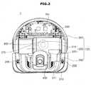
- FIG. 2 is a plan view illustrating the robot cleaner 1 according to the embodiment of the present disclosure when an external housing 301 (see FIG. 4 ) and a top housing 303 (see FIG. 4 ) of a second upper housing 300 are removed
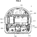
- FIG. 3 is a plan view illustrating the robot cleaner 1 according to one embodiment of the present disclosure when a first upper housing 200 and an external housing 301, a top housing 303, a dust collecting container 310, a suction motor cover 302 (see FIG. 5 ), and the like of the second upper housing 300 are removed.
- a power unit 350 which supplies power for driving the main body may be coupled to an inner side of the second upper housing 300.
- the power unit 350 may include a battery (not shown), a main board 351, and a display (not shown) positioned above the main board 351 and configured to display status of the robot cleaner.
- the power unit 350 may be disposed to be positioned behind the dust collecting unit 330.
- the battery is provided with a rechargeable secondary battery, and recharged by receiving power from a docking station (not shown) when the main body finishes a cleaning process and is coupled to the docking station.
- the suction motor 320 may be positioned inside a suction motor cover 302 (see FIG. 5 ).
- the suction motor 320 may be coupled to a side surface of the dust collecting container 310.
- the driving wheel 610 may be disposed at each side surface of the dust collecting container 310 and the suction motor 320.
- the dust collecting container 310, the suction motor 320, and the driving wheel 610 may be disposed along a lateral direction of the mainbody. That is, the dust collecting container 310, the suction motor 320, and the driving wheel 610 may be disposed in an almost straight line shape.
- At least a part of the dust collecting container 310 may be coupled to be exposed to the exterior. That is, an additional housing is not coupled to the top surface of the dust collecting container 310. Accordingly, a user may check the amount of dust in the dust collecting container 310 with naked eyes.
- a cyclone 370 may be installed in the dust collecting container 310. As illustrated in FIG. 2 , the cyclone 370 may be disposed in the dust collecting container 310 adjacent to the suction motor 320. In addition, the second upper housing 300 may include a container installation portion 312 in which the dust collecting container 310 is installed.
- An obstacle detecting sensor 230 may be provided in the first upper housing 200.
- a front portion of the first upper housing 200 may be provided in a rectangular shape to suction in dust by being pressed forward and sideward in the moving direction. Accordingly, it is possible to suction in dust by being maximally pressed against a wall surface. Accordingly, the robot cleaner 1 according to the embodiment of the present disclosure may efficiently suction in dust on a wall surface even without an additional side brush.
- FIG. 4 is an exploded view illustrating components of the second upper housing 300 of the robot cleaner 1 according to one embodiment of the present disclosure.
- the second upper housing 300 may include a top housing 303 coupled to an upper portion of the robot cleaner 1 and a rear housing 343 covering from a rear side of the second upper housing 300 to the driving wheel 610.
- an area corresponding to the display 352 may be provided to be open so that a status displayed on the display 352 may be projected therethrough.
- the dust collecting container 310 may be coupled to the top housing 303.
- a separate external housing 301 coupled to an upper portion of the power unit 350 may be coupled to an outer side of the top housing 303.
- the external housing 301 may be provided so that a status of the display 352 may be projected therethrough.
- the suction motor cover 302 may be coupled to an upper portion of the suction motor 320.
- the suction motor 320 may be coupled to the second upper housing 300, the top housing 303 may be inserted into the second upper housing 300, and the suction motor cover 302 may be coupled to the top housing 303.
- the suction motor cover 302 is assembled for preventing foreign materials from being inserted into the suction motor 320.
- the rear housing 343 may be assembled to surround each of the driving wheels 341 and 342.
- the robot cleaner 1 may efficiently use space by efficiently arranging components thereof. Accordingly, a size of the dust collecting container 310 may be increased.
- FIG. 5A is a view illustrating a side surface of the robot cleaner 1 according to the embodiment of the present disclosure.
- a height between a floor surface G1 and the first upper housing 200 may be different from a height between the floor surface G1 and the second upper housing 300.
- the height between the floor surface and the first upper housing 200 may be less than the height between the floor surface and the second upper housing 300. Since the height of the first upper housing 200 is less than the height of the second upper housing 300, there is an effect where the robot cleaner 1 appears to have a relatively small size as sizes of the dust collecting container 310 and the power unit 350 positioned in the second upper housing 300 are increased. Accordingly, an amount of dust stored in the miniaturized robot cleaner 1 may be increased and driving time may be increased without additional recharging.
- the height of the first upper housing 200 is relatively low, obstacles positioned on a floor surface may be efficiently detected, and a blind spot in which the obstacle detecting sensor 230 cannot detect may be prevented from occurring.
- connection member 400 is assembled between the first upper housing 200 and the second upper housing, it is not limited thereto, and the first upper housing 200 and the second upper housing may also be integrally injection molded without a separate border therebetween. In this case, the first upper housing 200 and the second upper housing 300 may be formed in an approximately streamlined shape.
- FIG. 5B is a view illustrating the side surface of the robot cleaner 1 when a driving wheel 610 of the robot cleaner according to the embodiment of the present disclosure protrudes downward.
- the driving wheel 610 may be provided to protrude downward from the robot cleaner 1 so as to maintain a state in which the driving wheel 610 is in contact with a surface while the robot cleaner 1 is driving.
- the robot cleaner 1 may be continuously driven by being in contact with the surface since the driving wheel 610 protrudes downward.
- the constant driving performance may be maintained only when a traction force due to the driving wheel 610 being pressed against the surface is maintained as much as when the driving wheel 610 is positioned at a normal position.
- a traction force of the robot cleaner 1 will be described in detail with a configuration of the driving unit 600.
- the driving unit 600 on the right side based on a direction in which the robot cleaner 1 drives will be described as an example, and unless the context particularly indicates otherwise, the same description will also apply to the driving unit 600 on the left side based on the direction in which the robot cleaner 1 drives.
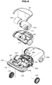
- FIG. 6 is a perspective view illustrating a lower housing of the robot cleaner according to the embodiment of the present disclosure
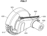
- FIG. 7 is a perspective view illustrating the driving unit according to one embodiment of the present disclosure seen from a direction opposite that of FIG. 6
- FIG. 8 is an exploded perspective view illustrating a part of the configuration of the driving unit according to the embodiment of the present disclosure.
- the driving units 600 may be provided in the lower housing 500. Specifically, the driving units 600 may be provided at both sides of the lower housing 500.
- the lower housing 500 may be provided with a seating portion (not shown) on which the driving unit 600 is seated and a driving motor seating portion 520 on which the driving motor 650 is seated.
- the driving unit 600 may be provided to be detachable from the lower housing 500 for easy separation therefrom when a problem in driving occurs while the robot cleaner 1 is driving.
- the driving motor 650 may be easily separated from the driving motor seating portion 520.
- the driving unit 600 may include the driving wheel 610, a housing 620 which covers a configuration of the driving unit 600, such as the driving wheel 610, a driving motor 650 which generates a driving force, a driving arm 630 which supports the driving motor 650 so that the driving motor 650 protrudes downward from the robot cleaner 1, and an elastic member 640 which transfers an elastic force to the driving wheel 610 and generates a traction force of the robot cleaner 1.
- the driving wheel 610 Since the driving shaft 611of the driving wheel 610 is assembled into a driving wheel assembly groove 631 of the driving arm 630, the driving wheel 610 may be rotatably supported by the driving arm 630.
- the driving arm 630 may be provided to be rotatable about a rotation shaft 633 positioned at the center of a rotation protrusion 632.
- a driving motor assembly portion 634 is provided at one side of the driving arm 630, one side of the driving motor 650 may be inserted into the driving arm 630.
- the driving motor assembly portion 634 may be provided in a ring type cylindrical shape to protrusively extend from one side of the driving arm 630.
- An external circumferential surface of the driving motor assembly portion 634 may be rotatably supported by a driving arm seating portion 621 which is cut from the housing 620 in a circular shape.
- a driving shaft 651 which transfers a rotational force generated from the driving motor 650 may be positioned inside the driving arm 630 through the driving motor assembly portion 634 to transfer the rotational force to a gear portion (not shown) provided inside the driving arm 630.
- the gear portion may transfer the rotational force which has been transferred through the driving shaft 651 to the driving wheel assembly groove 631 to rotate the driving wheel 610.
- the driving motor 650 may not be directly inserted into the driving arm 630, and only the driving shaft 651 may be inserted into the driving arm 630, unlike the embodiment of the present disclosure.
- the rotation protrusion 632 may be provided to extend from the other side of the driving arm 630 in a cylindrical shape.
- the rotation protrusion 632 may be inserted into an auxiliary housing (not shown) provided at a side from which the rotation protrusion 632 protrudes, to be rotatably supported.
- the rotation protrusion 632 may be provided to correspond to a central shaft of the driving motor assembly portion 634. Specifically, the rotation protrusion 632 may be provided to correspond to an axis direction of the driving shaft 651 which may be regarded as the rotation shaft of the rotation protrusion 632 and the driving motor 650.
- the central shaft of the driving motor assembly portion 634 and the rotation shaft 633 may be provided to be matched.
- the driving motor assembly portion 634 which protrudes from one side of the driving arm 630 and the rotation protrusion 632 which protrudes from the other side of the driving arm 630 are respectively supported by the housing 620 and the auxiliary housing (not shown), the driving arm 630 may rotate about the rotation shaft 633.
- the driving arm 630 may rotate downward of the robot cleaner 1 in the direction of the gravity.
- the driving arm 630 may rotate downward of the robot cleaner 1 until a lower side surface 636 of the driving arm 630 is in contact with the driving arm support portion 530 provided at a lower side of the lower housing 500.
- the driving wheel 610 may protrude downward from the robot cleaner 1 in conjunction with the rotational displacement of the driving arm 630.
- the driving unit 600 may include an elastic member 640 supported between a support protrusion 635 which extends from one side of the driving arm 630 and a support hook 625 positioned at the housing 620.
- the elastic member 640 may serve to improve a traction force of the driving wheel 610 by continuously pressing the driving wheel 610.
- One side of the elastic member 640 may be supported by the support protrusion 635 moved in conjunction with rotation of the driving arm 630, and the other side of the elastic member 640 may be supported by the support hook 625 which is provided in the housing 620 and has a constant displacement value when the driving arm 630 rotates.
- the length of the elastic member 640 changes in conjunction with rotation of the driving arm 630, so that an elastic force of the elastic member 640 may change.
- the housing 620 may include a housing assembly portion 622 which extends from one side of a lower end to an outside of a side surface of the lower housing 500 so as to be seated on the lower housing 500 and be assembled.
- the housing assembly portion 622 may include a hollow to be coupled by a screw which passes through the lower housing 500 and the hollow or may be coupled by a protrusion (not shown) which extends upward from the lower housing 500 to correspond to the hollow of the housing assembly portion 622.
- the housing assembly portion 622 may be provided in a plural number unlike the embodiment of the present disclosure.
- a single or the plurality of housing assembly portions 622 may be provided at the outside of a rotation radius of the support protrusion 635 so as not to interfere with rotation of the support protrusion 635 when provided adjacent to the support protrusion 635.
- the traction force of the driving wheel 610 is not constant due to change in an elastic force of the elastic member 640, and this will be described below.
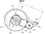
- FIG. 9 is a view illustrating a side surface of the part of the configuration of the driving unit according to the embodiment of the present disclosure
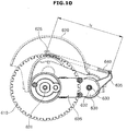
- FIG. 10 is a view illustrating a side surface of the driving unit when a driving wheel of the driving unit according to the embodiment of the present disclosure protrudes downward
- FIG. 11 is a perspective view illustrating a part of the configuration of the driving unit according to the embodiment of the present disclosure
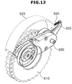
- FIG. 12 is a perspective view illustrating a part of the configuration of the driving unit when the driving wheel of the driving unit according to the embodiment of the present disclosure protrudes downward.
- the driving wheel 610 and the housing 620 are displayed as dotted lines in the drawings.
- FIGS. 9 and 11 are views illustrating the driving unit 600 when the driving wheel 610 does not protrudes.
- the driving wheel 610 may be inserted into the housing 620 to be adjacent to an inside of the housing and may be pressed by the elastic member 640.
- FIGS. 10 and 12 are views illustrating the driving unit 600 when the driving wheel 610 protrudes downward from the robot cleaner 1.
- a driving wheel assembly portion 631 disposed on the left of the rotation shaft 633 with respect to a side surface of the driving unit 600 and the driving wheel 610 supported by the driving wheel assembly portion 631 may move downward from the robot cleaner 1.
- the driving arm 630 rotates in the direction of gravity, the driving arm 630 rotates in the counterclockwise direction. Accordingly, the driving wheel 610 provided at the left of the rotation shaft 633 may move downward from the robot cleaner 1, and, on the contrary, the support protrusion 635 provided at the right of the rotation shaft 633 and one side of the elastic member 640 supported by one side of the support protrusion 635 may move upward in the robot cleaner 1.
- a length l1 of the elastic member before the driving wheel 610 protrudes may be greater than a length 12 of the elastic member when the driving wheel 610 protrudes.
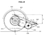
- FIG. 13 is a schematic view illustrating a configuration related to a traction force of the driving unit according to the embodiment of the present disclosure
- FIG. 14 is a schematic view illustrating the configuration related to the traction force of the driving unit when the driving wheel of the driving unit according to the embodiment of the present disclosure partially protrudes downward
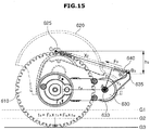
- FIG. 15 is a schematic view illustrating a configuration related to the traction force of the driving unit when the driving wheel of the driving unit according to the embodiment of the present disclosure completely protrudes downward.
- a traction force f of the driving wheel 610 has to be constant so that the robot cleaner 1 drives stably.
- the traction force f is a force pressed toward the surface.
- the traction force f may be the sum of a torque value obtained as a gravitational acceleration value Fw of the mass of the driving wheel 610 according to the mass of the driving wheel 610 times a perpendicular distance rw between a direction of the gravitational acceleration value Fw and a rotation point A positioned at the rotation shaft 633 which is a reference point about which the driving wheel 610 moves downward, and a torque value obtained as an elastic force F of the elastic member 640 which presses the driving wheel 610 times a perpendicular distance r (hereinafter, referred to as a second straight line) between a direction of the elastic force F and the rotation point A.
- the torque value of gravitational acceleration due to the mass of the driving wheel 610 (Fw * rw) is constant.
- the mass of the driving wheel 610 is constant and as the driving wheel 610 protrudes, a displacement value of the driving arm 630 in contact with the driving wheel 610 changes, so that the center of gravity g of the entire driving wheel 610 may change, however, the change is very small.
- the traction force f may be changed according to the value (F * r).
- the length of the elastic member 640 changes as the driving wheel 610 protrudes, the elastic force F of the elastic member 640 may change, and thus the torque value (F * r) according to the elastic force F may be changed and the total traction force f of the driving wheel 610 may be changed.
- the length of the first straight line X may decrease when the driving wheel 610 moves downward.
- the driving wheel 610 positioned at the left of the rotation point A is lowered and the first support point B positioned at the right of the rotation point A of the driving arm 630 is raised, and thus a height difference h between the first support point B and the second support point C decreases and the length of the first straight line X also decreases in conjunction therewith.
- the elastic force F might decreases and thus the total tractino force f might decrease.
- the second straight line r increase when the driving wheel 610 protrude downward from the robot cleaner 1, a change amount of the total torque value of the elastic force F may be maintained in a constant level
- the traction force f of the driving wheel 610 is prevented from being rapidly decreased when the length of the second straight line r increases while the driving wheel 610 is protruding downward from the robot cleaner 1.
- the second support point C is positioned at the housing 620
- the first support point B is positioned at the rotatably provided driving arm 630
- the rotation point A is positioned at a rotation shaft of the driving arm 630, and there is no change in the displacement value of the rotation point A and the second support point C while the driving wheel 610 is protruding, and thus the value of ⁇ may be changed according to movement of the first support point B.
- the first support point B rotates about the rotation point A in the counterclockwise direction, approaches the second support point C, and thus the value of ⁇ may be increased in conjunction therewith.
- a value of sin ⁇ may continually increase while the driving wheel 610 is protruding downward.
- the elastic force F of the elastic member 640 may decrease, on the contrary, in a range in which the value of ⁇ maintains an acute angle, the value of sin ⁇ may increase and thus the traction force f may be maintained to be a substantially constant level.
- the first support point B and the second support point C may be provided to have the value of ⁇ in an acute angle while the driving wheel 610 is protruding.
- a value of ⁇ 1 formed when the driving wheel 610 does not protrude may be less than a value of ⁇ 2 formed when the driving wheel 610 protrudes downward from the robot cleaner 1 and a value of ⁇ 3 formed when the driving wheel 610 finishes protruding.
- the length X3 of the first straight line becomes a minimum, and thus the elastic force F3 value becomes a minimum.
- the value of ⁇ 3 may be provided to be greater than the values of ⁇ 1 and ⁇ 2 when the driving wheel 610 finishes protruding.
- the maximum value of ⁇ 3 may be 90°.
- the value of ⁇ may be provided to be an acute angle satisfying ⁇ 1 ⁇ ⁇ 2 ⁇ ⁇ 3 always.
- the value of ⁇ 1 may be preferably provided to be less than 50°.
- the value of ⁇ 1 may be adjusted through an extension length and an angle of the support protrusion 635. However, a suitable value of ⁇ 1 may be set according to a volume of the lower housing 500 in which the driving unit 600 is seated.
- the length of the second straight line r may be provided to be increased while the driving wheel 610 is moving downward.
- the second straight line may have the length r satisfying r1 ⁇ r2 ⁇ r3 always.
- the second support point C may always be positioned higher than the first support point B. This is because, if the second support point C positioned lower than the first support point B while the driving wheel 610 is protruding, the length r3 of the second straight line when the driving wheel 610 finishes protruding might be less than the length r2 of the second straight line in the middle of the protruding of the driving wheel 610.
- the first support point B may be always provided above the rotation point A.
- One side of the elastic member 640 may be supported by the support protrusion 635, and the other side thereof may be supported by the support hook 625. Accordingly, the first support point B may be positioned on the support protrusion 635, and the second support point C may be positioned on the support hook 625.
- the support protrusion 635 may be provided to extend in a direction opposite the driving wheel assembly groove 631 with respect to the rotation shaft A.
- the support protrusion 635 may be provided with a groove in a hook shape to support one side of the elastic member 640.
- One side of the elastic member 640 may be assembled into the groove in a hook shape and supported by the support protrusion 635, and the first support point B may be provided at a side of the groove in a hook shape in contact with the elastic member 640.
- the first support point B may be provided to be positioned in a range in which the support protrusion 635 maintains the value of ⁇ at an acute angle and simultaneously increases while the driving wheel 610 is protruding.
- the support protrusion 635 receives a tensile force from the elastic member 640 due to an elastic force, a predetermined magnitude of hardness may be needed. Accordingly, the support protrusion 635 may be provided to have a certain thickness to maintain the predetermined magnitude of hardness. The thickness of the support protrusion 635 may be changed to correspond to the elastic force of the elastic member 640.
- the sizes of the upper and lower housings 100 and 500 except a dust collecting portion of the robot cleaner 1 decrease and a gap between elements seated on the lower housing 500 may be narrow.
- the support protrusion 635 may be formed of a steel member capable of maintaining a significant hardness with a small thickness so that the support protrusion 635 is provided in the narrow space.
- the support protrusion 635 may be formed with a separate steel member without being integrally formed with the driving arm 630, and may be coupled to the driving arm 630.
- the thickness of the support protrusion 635 may decrease and the support protrusion 635 may be rotatably provided in conjunction with the driving arm 630 without being interfered with by elements provided to be pressed against the lower housing 500.
- An assembly portion (not shown) in which the support protrusion 635 is assembled is provided at one side of the driving arm 630 to fix the support protrusion 635 and the support protrusion 635 may be supported by being coupled by a screw member (not shown).
- the support hook 625 may be provided to protrusively extend from the housing 620 toward one side.
- the groove in a hook shape may be provided at support hook 625 to support the other side of the elastic member 640.
- the other side of the elastic member 640 may be assembled into the groove in the hook shape and supported by the support hook 625, and the second support point B may be provided at the groove in the hook shape in contact with the elastic member 640.
- the support hook 625 may be provided at the housing 620 and support the elastic member 640 without a position movement while the driving arm 630 is pivoting, unlike the support protrusion 635.
- a driving unit and a robot cleaner having the same can complement an elastic force of an elastic member changed according to the displacement of a driving wheel by improving a support point of the elastic member so that the improved robot cleaner can be continuously and stably driven on a floor surface having steps, thereby improving efficiency of the robot cleaner.
Landscapes
- Engineering & Computer Science (AREA)
- Mechanical Engineering (AREA)
- Automation & Control Theory (AREA)
- Chemical & Material Sciences (AREA)
- Combustion & Propulsion (AREA)
- Transportation (AREA)
- Electric Vacuum Cleaner (AREA)
- Electric Suction Cleaners (AREA)
- Robotics (AREA)
Description
- The present invention relates to a driving unit and a robot cleaner having the same, and more particularly, to a structure which improves a traction force of a driving unit.
- In general, a robot cleaner is an apparatus which automatically cleans an area to be cleaned by moving about in the area by itself and suctioning in foreign materials such as particles from a floor surface even without a user's operation.
- Such a robot cleaner includes driving wheels for driving a robot cleaner body, and the driving wheels drive a robot cleaner body using a frictional force generated between the driving wheels and a floor surface being in contact therewith.
- To generate the frictional force, a force which presses the driving wheels toward the surface is needed, and this is related to a traction force of the robot cleaner.
- The traction force of the driving wheels has to be constantly maintained regardless of a state or a condition of the floor surface so that the robot cleaner maintains a constant driving performance on various floor conditions, such as a hard floor or carpet, and a floor where steps exist.
- Although elastic members such as a tension coil spring have been conventionally used for pressing the driving wheels toward a floor surface, the elastic members have a big difference in a force which presses the driving wheels due to change in an elastic force depending on the displacement of the driving wheels.
-
EP2679130A1 relates to a robot cleaner according to the preamble ofclaim 1 including an elastic member to raise and lower the driving wheel of a robot cleaner relative to the main body. - Therefore, it is an aspect of the present disclosure to provide an improved driving unit where a change in a traction force of a driving wheel is not big even when a displacement of the driving wheel changes while a robot cleaner is moving on a surface having a step and a robot cleaner having the same.
- Additional aspects of the disclosure will be set forth in part in the description which follows and, in part, will be obvious from the description, or may be learned by practice of the disclosure.
- In accordance with an aspect of the invention, there is provided a robot cleaner according to
claim 1. - In accordance with one aspect of the present disclosure, a robot cleaner includes a main body, and a driving unit including a driving wheel which drives the main body, wherein the driving unit includes a housing, a driving motor which generates a rotational force for driving the driving wheel, a driving arm which rotates about a rotation point so that the driving wheel is supported to protrude downward from the main body, and an elastic member supported between a first support point provided at one side of the driving arm and a second support point provided at the housing, wherein an angle (θ) formed at the first support point by the rotation point and the second support point is maintained at an acute angle while the driving arm is rotating.
- The driving arm may rotate about the rotation point in between a first position and a second position in which the driving wheel protrudes toward the outside of the main body, and when the angle formed when the driving arm is positioned at the first position is referred to as a first angle, and the angle formed when the driving arm is positioned at the second position is referred to as a second angle, and the first angle may be less than the second angle.
- The first angle may be 50° or less.
- The second angle may be 90° or less.
- The driving arm may include a support protrusion which extends from the driving arm to protrude toward the outside of the housing and includes the first support point.
- The support protrusion may support one side of the elastic member and change a displacement of the elastic member in conjunction with the rotation of the driving arm.
- The housing may include a support hook having the second support point, and the support hook may support one side of the elastic member.
- The driving wheel may a traction force generated due to a frictional force with a surface when driving, and the traction force of the driving wheel may be maintained at a constant level in all cases where the driving wheel protrudes toward the outside of the main body and the driving wheel is seated inside the main body.
- In accordance with the present disclosure, a robot cleaner includes a main body, and a driving unit including a driving wheel which drives the main body, wherein the driving unit includes a driving arm which rotates about a rotation point so that the driving wheel is supported to move downward from the main body and an elastic member supported between a first support point which is provided at one side of the driving arm and moved in conjunction with the driving arm and a second support point which is fixed, wherein the second support point is always positioned above the first support point or at least the same horizontal line.
- A height of a position at which the first support point is positioned will be raised while the driving wheel is moving downward from the main body.
- The first support point may be positioned above the rotation point.
- In accordance with still another aspect of the present disclosure, a robot cleaner includes a main body, and a driving unit including a driving wheel which drives the main body, wherein the driving unit includes a driving motor which generates a rotational force which drives the driving wheel, a driving arm which rotates about a rotation point so that the driving wheel is supported to protrude downward from the main body, and an elastic member supported between a first support point which is provided at one side of the driving arm and moves in conjunction with the driving arm and and second support point which is fixed, and with respect to a first straight line which connects the first support point to the second support point, and a second straight line forms a right angle with the first straight line at the rotation point while in contact with the first straight line, the second straight line when the driving wheel protrudes downward from the main body may have a length greater than a line when the driving wheel is seated in the main body.
- The length of the second straight line may have a maximum value when the wheel rotates about the rotation point at a second position while rotating in between a first position and the second position in which the driving wheel protrudes toward the outside of the main body.
- The length of the second straight line may extend while the driving wheel is protruding downward from the main body.
- The driving unit may further include a housing in which the driving wheel, a driving motor, and a driving arm are seated, and the rotation point and the second support point may be provided inside the housing.
- The driving arm may include a support protrusion which extends from the driving arm to protrude toward an outside of the housing and includes the first support point.
- The support protrusion may support one side of the elastic member and change a displacement of the elastic member in conjunction with the rotation of the driving arm.
- The housing may include a support hook having the second support point, and the support hook may support one side of the elastic member.
- An angle formed around the first support point by the rotation point and the second support point may be maintained at an acute angle while the driving arm is rotating.
- The driving arm may rotate about the rotation point in between a first position and a second position in which the driving arm protrudes toward an outside of the main body, and when the angle formed when the driving arm is positioned at the first position is referred to as a first angle, and the angle formed when the driving arm is positioned at the second position is referred to as a second angle, and the first angle may be less than the second angle.
- A driving unit which is installed in a robot cleaner according to an aspect of the present disclosure and drives the robot cleaner may include a housing, a driving wheel which drives a main body, a driving motor which generates a rotational force which drives the driving wheel, a driving arm which rotates about a rotation point so that the driving wheel is supported to move between a first position and a second position, and an elastic member supported in between a first support point provided at one side of the driving arm and asecond support point provided at the housing, wherein an angle θ formed around the first support point by the rotation point and the second support point increases while the driving arm is moving from the first position to the second position.
- These and/or other aspects of the disclosure will become apparent and more readily appreciated from the following description of the embodiments, taken in conjunction with the accompanying drawings of which:
-
FIG. 1 is a perspective view illustrating an exterior of a robot cleaner according to one embodiment of the present disclosure; -
FIG. 2 is a plan view illustrating the robot cleaner according to the embodiment of the present disclosure when an external housing and a top housing of a second upper housing are removed; -
FIG. 3 is a plan view illustrating the robot cleaner according to the embodiment of the present disclosure when an external housing of a first upper housing, the external housing and so on of the second upper housing are removed; -
FIG. 4 is an exploded perspective view illustrating a part of the configuration of the robot cleaner according to the embodiment of the present disclosure; -
FIG. 5A is a view illustrating a side surface of the robot cleaner according to the embodiment of the present disclosure; -
FIG. 5B is a view illustrating the side surface of the robot cleaner when a driving wheel of the robot cleaner according to the embodiment of the present disclosure protrudes downward; -
FIG. 6 is a perspective view illustrating a lower housing of the robot cleaner according to the embodiment of the present disclosure; -
FIG. 7 is a perspective view illustrating a driving unit according to one embodiment of the present disclosure; -
FIG. 8 is an exploded perspective view illustrating a part of the configuration of the driving unit according to the embodiment of the present disclosure; -
FIG. 9 is a view illustrating a side surface of a part of the configuration of the driving unit according to the embodiment of the present disclosure; -
FIG. 10 is a view illustrating a side surface of the driving unit when a driving wheel of the driving unit according to the embodiment of the present disclosure protrudes downward; -
FIG. 11 is a perspective view illustrating a part of the configuration of the driving unit according to the embodiment of the present disclosure; -
FIG. 12 is a perspective view illustrating a part of the configuration of the driving unit when the driving wheel of the driving unit according to the embodiment of the present disclosure protrudes downward; -
FIG. 13 is a schematic view illustrating a configuration related to a traction force of the driving unit according to the embodiment of the present disclosure; -
FIG. 14 is a schematic view illustrating the configuration related to the traction force of the driving unit when the driving wheel of the driving unit according to the embodiment of the present disclosure partially protrudes downward; and -
FIG. 15 is a schematic view illustrating a configuration related to the traction force of the driving unit when the driving wheel of the driving unit according to the embodiment of the present disclosure completely protrudes downward. - Hereinafter, embodiments of the present disclosure will be described in detail with reference to the accompanying drawings.
-
Driving units 600 according to one embodiment of the present disclosure may be installed in arobot cleaner 1. In addition, besides therobot cleaner 1, thedriving unit 600 may also be installed in other robots or moving apparatus driven by driving wheels and the like. Hereinafter, it is assumed that thedriving unit 600 is installed in therobot cleaner 1, and thedriving unit 600 and therobot cleaner 1 having the same will be described in detail. -
FIG. 1 is a perspective view illustrating an exterior of a robot cleaner according to one embodiment of the present disclosure. - As illustrated in
FIG. 1 , therobot cleaner 1 includes a main body forming an exterior and anupper housing 100 forming at least a part of the exterior of the main body. - The
upper housing 100 includes a firstupper housing 200 formed in the front and a secondupper housing 300 formed in the back of the firstupper housing 200. Aconnection member 400 which connects the firstupper housing 200 and the secondupper housing 300 may be positioned between the firstupper housing 200 and the secondupper housing 300. - A
dust collecting unit 330 configured to store dust may be coupled to the secondupper housing 300. Thedust collecting unit 330 may include asuction motor 320 which provides a driving force which suctions in dust and adust collecting container 310 which stores the suctioned-in dust. - A
grip portion 311 provided to be gripped by a user may be provided at thedust collecting container 310. The user may grip thegrip portion 311, turn thedust collecting container 310, and separate thedust collecting container 310 from the secondupper housing 300. The user may separate thedust collecting container 310 and remove dust accumulated in thedust collecting container 310. - A
lower housing 500 provided to be coupled to the secondupper housing 300 may be provided at a lower portion of the secondupper housing 300. Thedriving unit 600 which drives the main body may be provided at thelower housing 500. The drivingunit 600 may include drivingwheels 610 for moving the main body and a roller 510 (seeFIG. 5 ) rotatably provided to minimize the load of movement of the main body. According to one embodiment of present disclosure, the drivingwheels 610 may be coupled to both side surfaces of thelower housing 500. - A brush unit (not shown) configured to sweep dust on a floor for collecting may be provided at the first
upper housing 200. Abumper 210 for buffering noise and an impact generated when therobot cleaner 1 bumps into a wall surface during moving may be coupled to a front portion of the firstupper housing 200. Also, anadditional buffer member 215 may be coupled to thebumper 210. - An
entry blocking sensor 235 may be protrusively provided on a top surface of the firstupper housing 200. Theentry blocking sensor 235 may prevent therobot cleaner 1 from entering a predetermined area by sensing infrared light. According to one embodiment of present disclosure, theentry blocking sensor 235 may be provided on both sides of the firstupper housing 200. -
FIG. 2 is a plan view illustrating therobot cleaner 1 according to the embodiment of the present disclosure when an external housing 301 (seeFIG. 4 ) and a top housing 303 (seeFIG. 4 ) of a secondupper housing 300 are removed, andFIG. 3 is a plan view illustrating therobot cleaner 1 according to one embodiment of the present disclosure when a firstupper housing 200 and anexternal housing 301, atop housing 303, adust collecting container 310, a suction motor cover 302 (seeFIG. 5 ), and the like of the secondupper housing 300 are removed. - As illustrated in
FIGS. 2 and3 , apower unit 350 which supplies power for driving the main body may be coupled to an inner side of the secondupper housing 300. - The
power unit 350 may include a battery (not shown), amain board 351, and a display (not shown) positioned above themain board 351 and configured to display status of the robot cleaner. Thepower unit 350 may be disposed to be positioned behind thedust collecting unit 330. - The battery is provided with a rechargeable secondary battery, and recharged by receiving power from a docking station (not shown) when the main body finishes a cleaning process and is coupled to the docking station.
- The
suction motor 320 may be positioned inside a suction motor cover 302 (seeFIG. 5 ). Thesuction motor 320 may be coupled to a side surface of thedust collecting container 310. According to one embodiment of present disclosure, thedriving wheel 610 may be disposed at each side surface of thedust collecting container 310 and thesuction motor 320. - Accordingly, the
dust collecting container 310, thesuction motor 320, and thedriving wheel 610 may be disposed along a lateral direction of the mainbody. That is, thedust collecting container 310, thesuction motor 320, and thedriving wheel 610 may be disposed in an almost straight line shape. - According to one embodiment of present disclosure, at least a part of the
dust collecting container 310 may be coupled to be exposed to the exterior. That is, an additional housing is not coupled to the top surface of thedust collecting container 310. Accordingly, a user may check the amount of dust in thedust collecting container 310 with naked eyes. - A
cyclone 370 may be installed in thedust collecting container 310. As illustrated inFIG. 2 , thecyclone 370 may be disposed in thedust collecting container 310 adjacent to thesuction motor 320. In addition, the secondupper housing 300 may include acontainer installation portion 312 in which thedust collecting container 310 is installed. - An
obstacle detecting sensor 230 may be provided in the firstupper housing 200. - A front portion of the first
upper housing 200 may be provided in a rectangular shape to suction in dust by being pressed forward and sideward in the moving direction. Accordingly, it is possible to suction in dust by being maximally pressed against a wall surface. Accordingly, therobot cleaner 1 according to the embodiment of the present disclosure may efficiently suction in dust on a wall surface even without an additional side brush. -
FIG. 4 is an exploded view illustrating components of the secondupper housing 300 of therobot cleaner 1 according to one embodiment of the present disclosure. - The second
upper housing 300 may include atop housing 303 coupled to an upper portion of therobot cleaner 1 and arear housing 343 covering from a rear side of the secondupper housing 300 to thedriving wheel 610. - In the case of the
top housing 303, an area corresponding to thedisplay 352 may be provided to be open so that a status displayed on thedisplay 352 may be projected therethrough. Thedust collecting container 310 may be coupled to thetop housing 303. A separateexternal housing 301 coupled to an upper portion of thepower unit 350 may be coupled to an outer side of thetop housing 303. Theexternal housing 301 may be provided so that a status of thedisplay 352 may be projected therethrough. - In addition, the
suction motor cover 302 may be coupled to an upper portion of thesuction motor 320. Thesuction motor 320 may be coupled to the secondupper housing 300, thetop housing 303 may be inserted into the secondupper housing 300, and thesuction motor cover 302 may be coupled to thetop housing 303. According to one embodiment of present disclosure, since theexternal housing 301 does not surround a region in which thesuction motor 320 is positioned, thesuction motor cover 302 is assembled for preventing foreign materials from being inserted into thesuction motor 320. - After the first driving wheel 341 and the second driving wheel 342 are coupled to both sides of the second
upper housing 300, therear housing 343 may be assembled to surround each of the driving wheels 341 and 342. - As described above, the
robot cleaner 1 according to the embodiment of present disclosure may efficiently use space by efficiently arranging components thereof. Accordingly, a size of thedust collecting container 310 may be increased. -
FIG. 5A is a view illustrating a side surface of therobot cleaner 1 according to the embodiment of the present disclosure. - As illustrated in
FIG. 5A , a height between a floor surface G1 and the firstupper housing 200 may be different from a height between the floor surface G1 and the secondupper housing 300. According to one embodiment of present disclosure, the height between the floor surface and the firstupper housing 200 may be less than the height between the floor surface and the secondupper housing 300. Since the height of the firstupper housing 200 is less than the height of the secondupper housing 300, there is an effect where therobot cleaner 1 appears to have a relatively small size as sizes of thedust collecting container 310 and thepower unit 350 positioned in the secondupper housing 300 are increased. Accordingly, an amount of dust stored in theminiaturized robot cleaner 1 may be increased and driving time may be increased without additional recharging. - In addition, since the height of the first
upper housing 200 is relatively low, obstacles positioned on a floor surface may be efficiently detected, and a blind spot in which theobstacle detecting sensor 230 cannot detect may be prevented from occurring. - According to one embodiment of present disclosure, although the
connection member 400 is assembled between the firstupper housing 200 and the second upper housing, it is not limited thereto, and the firstupper housing 200 and the second upper housing may also be integrally injection molded without a separate border therebetween. In this case, the firstupper housing 200 and the secondupper housing 300 may be formed in an approximately streamlined shape. -
FIG. 5B is a view illustrating the side surface of therobot cleaner 1 when adriving wheel 610 of the robot cleaner according to the embodiment of the present disclosure protrudes downward. - There are cases in which the
robot cleaner 1 passes over steps while therobot cleaner 1 is moving on a floor surface. For example, this corresponds to a case in which therobot cleaner 1 climbs a slope having a constant incline with respect to a surface or passes over a concave surface having a downward depth from a surface. - In the case of a step on a surface, since a lifting phenomenon in which the
driving wheel 610 is separated from the surface occurs, a frictional force with the floor surface may not be generated, and driving may be impossible. Accordingly, thedriving wheel 610 may be provided to protrude downward from therobot cleaner 1 so as to maintain a state in which thedriving wheel 610 is in contact with a surface while therobot cleaner 1 is driving. - As illustrated in
FIG. 5B , even when a driving surface is lowered from a general driving surface G1 to a level G3, therobot cleaner 1 may be continuously driven by being in contact with the surface since thedriving wheel 610 protrudes downward. - However, even with the
driving wheel 610 protruded, the constant driving performance may be maintained only when a traction force due to thedriving wheel 610 being pressed against the surface is maintained as much as when thedriving wheel 610 is positioned at a normal position. Hereinafter, a traction force of therobot cleaner 1 will be described in detail with a configuration of thedriving unit 600. - Hereinafter, the driving
unit 600 on the right side based on a direction in which therobot cleaner 1 drives will be described as an example, and unless the context particularly indicates otherwise, the same description will also apply to thedriving unit 600 on the left side based on the direction in which therobot cleaner 1 drives. -
FIG. 6 is a perspective view illustrating a lower housing of the robot cleaner according to the embodiment of the present disclosure,FIG. 7 is a perspective view illustrating the driving unit according to one embodiment of the present disclosure seen from a direction opposite that ofFIG. 6 , andFIG. 8 is an exploded perspective view illustrating a part of the configuration of the driving unit according to the embodiment of the present disclosure. - As illustrated in
FIG. 6 , the drivingunits 600 may be provided in thelower housing 500. Specifically, the drivingunits 600 may be provided at both sides of thelower housing 500. - The
lower housing 500 may be provided with a seating portion (not shown) on which thedriving unit 600 is seated and a drivingmotor seating portion 520 on which the drivingmotor 650 is seated. - The driving
unit 600 may be provided to be detachable from thelower housing 500 for easy separation therefrom when a problem in driving occurs while therobot cleaner 1 is driving. Particularly, the drivingmotor 650 may be easily separated from the drivingmotor seating portion 520. - As illustrated in
FIGS. 7 and8 , the drivingunit 600 may include thedriving wheel 610, ahousing 620 which covers a configuration of thedriving unit 600, such as thedriving wheel 610, a drivingmotor 650 which generates a driving force, a drivingarm 630 which supports the drivingmotor 650 so that the drivingmotor 650 protrudes downward from therobot cleaner 1, and anelastic member 640 which transfers an elastic force to thedriving wheel 610 and generates a traction force of therobot cleaner 1. - Since the driving shaft 611of the
driving wheel 610 is assembled into a drivingwheel assembly groove 631 of the drivingarm 630, thedriving wheel 610 may be rotatably supported by the drivingarm 630. - The driving
arm 630 may be provided to be rotatable about arotation shaft 633 positioned at the center of arotation protrusion 632. As a drivingmotor assembly portion 634 is provided at one side of the drivingarm 630, one side of the drivingmotor 650 may be inserted into the drivingarm 630. - The driving
motor assembly portion 634 may be provided in a ring type cylindrical shape to protrusively extend from one side of the drivingarm 630. - An external circumferential surface of the driving
motor assembly portion 634 may be rotatably supported by a drivingarm seating portion 621 which is cut from thehousing 620 in a circular shape. - A driving
shaft 651 which transfers a rotational force generated from the drivingmotor 650 may be positioned inside the drivingarm 630 through the drivingmotor assembly portion 634 to transfer the rotational force to a gear portion (not shown) provided inside the drivingarm 630. - The gear portion may transfer the rotational force which has been transferred through the driving
shaft 651 to the drivingwheel assembly groove 631 to rotate thedriving wheel 610. - The driving
motor 650 may not be directly inserted into the drivingarm 630, and only the drivingshaft 651 may be inserted into the drivingarm 630, unlike the embodiment of the present disclosure. - The
rotation protrusion 632 may be provided to extend from the other side of the drivingarm 630 in a cylindrical shape. Therotation protrusion 632 may be inserted into an auxiliary housing (not shown) provided at a side from which therotation protrusion 632 protrudes, to be rotatably supported. - The
rotation protrusion 632 may be provided to correspond to a central shaft of the drivingmotor assembly portion 634. Specifically, therotation protrusion 632 may be provided to correspond to an axis direction of the drivingshaft 651 which may be regarded as the rotation shaft of therotation protrusion 632 and the drivingmotor 650. - Accordingly, the central shaft of the driving
motor assembly portion 634 and therotation shaft 633 may be provided to be matched. - As the driving
motor assembly portion 634 which protrudes from one side of the drivingarm 630 and therotation protrusion 632 which protrudes from the other side of the drivingarm 630 are respectively supported by thehousing 620 and the auxiliary housing (not shown), the drivingarm 630 may rotate about therotation shaft 633. - The driving
arm 630 may rotate downward of therobot cleaner 1 in the direction of the gravity. The drivingarm 630 may rotate downward of therobot cleaner 1 until alower side surface 636 of the drivingarm 630 is in contact with the drivingarm support portion 530 provided at a lower side of thelower housing 500. - As described above, the
driving wheel 610 may protrude downward from therobot cleaner 1 in conjunction with the rotational displacement of the drivingarm 630. - As illustrated in
FIG. 7 , the drivingunit 600 may include anelastic member 640 supported between asupport protrusion 635 which extends from one side of the drivingarm 630 and asupport hook 625 positioned at thehousing 620. - The
elastic member 640 may serve to improve a traction force of thedriving wheel 610 by continuously pressing thedriving wheel 610. - One side of the
elastic member 640 may be supported by thesupport protrusion 635 moved in conjunction with rotation of the drivingarm 630, and the other side of theelastic member 640 may be supported by thesupport hook 625 which is provided in thehousing 620 and has a constant displacement value when the drivingarm 630 rotates. - As a displacement of the
support protrusion 635 changes, the length of theelastic member 640 changes in conjunction with rotation of the drivingarm 630, so that an elastic force of theelastic member 640 may change. - The
housing 620 may include a housing assembly portion 622 which extends from one side of a lower end to an outside of a side surface of thelower housing 500 so as to be seated on thelower housing 500 and be assembled. - The housing assembly portion 622 may include a hollow to be coupled by a screw which passes through the
lower housing 500 and the hollow or may be coupled by a protrusion (not shown) which extends upward from thelower housing 500 to correspond to the hollow of the housing assembly portion 622. - The housing assembly portion 622 may be provided in a plural number unlike the embodiment of the present disclosure. A single or the plurality of housing assembly portions 622 may be provided at the outside of a rotation radius of the
support protrusion 635 so as not to interfere with rotation of thesupport protrusion 635 when provided adjacent to thesupport protrusion 635. - The traction force of the
driving wheel 610 is not constant due to change in an elastic force of theelastic member 640, and this will be described below. -
FIG. 9 is a view illustrating a side surface of the part of the configuration of the driving unit according to the embodiment of the present disclosure,FIG. 10 is a view illustrating a side surface of the driving unit when a driving wheel of the driving unit according to the embodiment of the present disclosure protrudes downward,FIG. 11 is a perspective view illustrating a part of the configuration of the driving unit according to the embodiment of the present disclosure, andFIG. 12 is a perspective view illustrating a part of the configuration of the driving unit when the driving wheel of the driving unit according to the embodiment of the present disclosure protrudes downward. For the sake of convenience in the description, thedriving wheel 610 and thehousing 620 are displayed as dotted lines in the drawings. -
FIGS. 9 and11 are views illustrating thedriving unit 600 when thedriving wheel 610 does not protrudes. Thedriving wheel 610 may be inserted into thehousing 620 to be adjacent to an inside of the housing and may be pressed by theelastic member 640. -
FIGS. 10 and12 are views illustrating thedriving unit 600 when thedriving wheel 610 protrudes downward from therobot cleaner 1. - Since the driving
arm 630 rotates about therotation shaft 633, a drivingwheel assembly portion 631 disposed on the left of therotation shaft 633 with respect to a side surface of thedriving unit 600 and thedriving wheel 610 supported by the drivingwheel assembly portion 631 may move downward from therobot cleaner 1. - Specifically, since the driving
arm 630 rotates in the direction of gravity, the drivingarm 630 rotates in the counterclockwise direction. Accordingly, thedriving wheel 610 provided at the left of therotation shaft 633 may move downward from therobot cleaner 1, and, on the contrary, thesupport protrusion 635 provided at the right of therotation shaft 633 and one side of theelastic member 640 supported by one side of thesupport protrusion 635 may move upward in therobot cleaner 1. - Comparing
FIGS. 9 and10 , a length l1 of the elastic member before thedriving wheel 610 protrudes may be greater than alength 12 of the elastic member when thedriving wheel 610 protrudes. - This is because one side of the
elastic member 640 supported by thesupport protrusion 635 is raised by rotation of the drivingarm 630, a distance from the other side of theelastic member 640 supported by thesupport hook 625 decreases, and thus the length l1 of theelastic member 640 decreases. - Hereinafter, a traction force f of the
driving wheel 610 and thesupport protrusion 635 related to the traction force f will be described in detail. -
FIG. 13 is a schematic view illustrating a configuration related to a traction force of the driving unit according to the embodiment of the present disclosure,FIG. 14 is a schematic view illustrating the configuration related to the traction force of the driving unit when the driving wheel of the driving unit according to the embodiment of the present disclosure partially protrudes downward, andFIG. 15 is a schematic view illustrating a configuration related to the traction force of the driving unit when the driving wheel of the driving unit according to the embodiment of the present disclosure completely protrudes downward. - As describe above, a traction force f of the
driving wheel 610 has to be constant so that therobot cleaner 1 drives stably. - The traction force f is a force pressed toward the surface. Schematically, the traction force f may be the sum of a torque value obtained as a gravitational acceleration value Fw of the mass of the
driving wheel 610 according to the mass of thedriving wheel 610 times a perpendicular distance rw between a direction of the gravitational acceleration value Fw and a rotation point A positioned at therotation shaft 633 which is a reference point about which thedriving wheel 610 moves downward, and a torque value obtained as an elastic force F of theelastic member 640 which presses thedriving wheel 610 times a perpendicular distance r (hereinafter, referred to as a second straight line) between a direction of the elastic force F and the rotation point A. - The traction force f may be represented as f = (Fw * rw) + (F * r).
- The torque value of gravitational acceleration due to the mass of the driving wheel 610 (Fw * rw) is constant.
- The mass of the
driving wheel 610 is constant and as thedriving wheel 610 protrudes, a displacement value of the drivingarm 630 in contact with thedriving wheel 610 changes, so that the center of gravity g of theentire driving wheel 610 may change, however, the change is very small. - That is, the traction force f may be changed according to the value (F * r).
- As illustrated in
FIGS. 13 to 15 , the length of theelastic member 640 changes as thedriving wheel 610 protrudes, the elastic force F of theelastic member 640 may change, and thus the torque value (F * r) according to the elastic force F may be changed and the total traction force f of thedriving wheel 610 may be changed. - Specifically, when there is a first straight line X which connects a first support point B which supports one side of the
elastic member 640 and is provided on the drivingarm 630 to a second support point C which supports the other side of theelastic member 640 and is provided on thehousing 620, and corresponds to the length of the elastic member, the length of the first straight line X may decrease when thedriving wheel 610 moves downward. - As the driving
arm 630 rotates in the counterclockwise direction, thedriving wheel 610 positioned at the left of the rotation point A is lowered and the first support point B positioned at the right of the rotation point A of the drivingarm 630 is raised, and thus a height difference h between the first support point B and the second support point C decreases and the length of the first straight line X also decreases in conjunction therewith. - If the
driving wheel 610 protrudes downward from therobot cleaner 1, the elastic force F might decreases and thus the total tractino force f might decrease. However, since the second straight line r increase when thedriving wheel 610 protrude downward from therobot cleaner 1, a change amount of the total torque value of the elastic force F may be maintained in a constant level - Accordingly, the traction force f of the
driving wheel 610 is prevented from being rapidly decreased when the length of the second straight line r increases while thedriving wheel 610 is protruding downward from therobot cleaner 1. - When a third straight line Y connects the rotation point A to the first support point B, and θ indicates an angle formed between the first straight line X and the third straight line Y at the first support point B, the second straight line r may have a value r = Y * sign θ.
- The second support point C is positioned at the
housing 620, the first support point B is positioned at the rotatably provided drivingarm 630, the rotation point A is positioned at a rotation shaft of the drivingarm 630, and there is no change in the displacement value of the rotation point A and the second support point C while thedriving wheel 610 is protruding, and thus the value of θ may be changed according to movement of the first support point B. - While the
driving wheel 610 is protruding downward, the first support point B rotates about the rotation point A in the counterclockwise direction, approaches the second support point C, and thus the value of θ may be increased in conjunction therewith. - While the driving
arm 630 is rotating, when the value of θ is maintained in a range from 0° to 90°, that is, an acute angle, a value of sin θ may continually increase while thedriving wheel 610 is protruding downward. - Accordingly, while the
driving wheel 610 is being lowered, the elastic force F of theelastic member 640 may decrease, on the contrary, in a range in which the value of θ maintains an acute angle, the value of sin θ may increase and thus the traction force f may be maintained to be a substantially constant level. - Therefore, according to the present disclosure directed to improve the traction force f when the
driving wheel 610 protrudes, the first support point B and the second support point C may be provided to have the value of θ in an acute angle while thedriving wheel 610 is protruding. - Specifically, while the value of θ is maintained as an acute angle, as illustrated in
FIG. 13 , a value of θ1 formed when thedriving wheel 610 does not protrude may be less than a value of θ2 formed when thedriving wheel 610 protrudes downward from therobot cleaner 1 and a value of θ3 formed when thedriving wheel 610 finishes protruding. - This is for increasing the value of sin θ while the
driving wheel 610 is protruding to offset a decrease in the elastic force F1 due to a length of the first straight line X1 when thedriving wheel 610 does not protrude being less than lengths of the first straight lines X2, X3 while thedriving wheel 610 is respectively protruding downward and finishes protruding. - In addition, when the
driving wheel 610 finishes protruding, the length X3 of the first straight line becomes a minimum, and thus the elastic force F3 value becomes a minimum. To offset this, the value of θ3 may be provided to be greater than the values of θ1 and θ2 when thedriving wheel 610 finishes protruding. - As describe above, since the value of θ3 is provided to be the acute angle, the maximum value of θ3 may be 90°.
- Accordingly, while the
driving wheel 610 is moving downward, the value of θ may be provided to be an acute angle satisfying θ1 < θ2 < θ3 always. The value of θ1 may be preferably provided to be less than 50°. - The value of θ1 may be adjusted through an extension length and an angle of the
support protrusion 635. However, a suitable value of θ1 may be set according to a volume of thelower housing 500 in which thedriving unit 600 is seated. - With respect to the second straight line r, since an entire torque value (F * r) increases according to the increase in the r value, the length of the second straight line r may be provided to be increased while the
driving wheel 610 is moving downward. - Accordingly, the second straight line may have the length r satisfying r1 < r2 < r3 always.
- While the
driving wheel 610 is protruding, the second support point C may always be positioned higher than the first support point B. This is because, if the second support point C positioned lower than the first support point B while thedriving wheel 610 is protruding, the length r3 of the second straight line when thedriving wheel 610 finishes protruding might be less than the length r2 of the second straight line in the middle of the protruding of thedriving wheel 610. - Similarly, while the
driving wheel 610 is protruding, the first support point B may be always provided above the rotation point A. - One side of the
elastic member 640 may be supported by thesupport protrusion 635, and the other side thereof may be supported by thesupport hook 625. Accordingly, the first support point B may be positioned on thesupport protrusion 635, and the second support point C may be positioned on thesupport hook 625. - Specifically, the
support protrusion 635 may be provided to extend in a direction opposite the drivingwheel assembly groove 631 with respect to the rotation shaft A. In addition, thesupport protrusion 635 may be provided with a groove in a hook shape to support one side of theelastic member 640. - One side of the
elastic member 640 may be assembled into the groove in a hook shape and supported by thesupport protrusion 635, and the first support point B may be provided at a side of the groove in a hook shape in contact with theelastic member 640. - Since the value of θ and the length r of the second straight line are defined by the first support point B, the first support point B may be provided to be positioned in a range in which the
support protrusion 635 maintains the value of θ at an acute angle and simultaneously increases while thedriving wheel 610 is protruding. - Since the
support protrusion 635 receives a tensile force from theelastic member 640 due to an elastic force, a predetermined magnitude of hardness may be needed. Accordingly, thesupport protrusion 635 may be provided to have a certain thickness to maintain the predetermined magnitude of hardness. The thickness of thesupport protrusion 635 may be changed to correspond to the elastic force of theelastic member 640. - To miniaturize the
robot cleaner 1, the sizes of the upper andlower housings robot cleaner 1 decrease and a gap between elements seated on thelower housing 500 may be narrow. - At this time, when the thickness becomes thick to maintain the hardness of the
support protrusion 635, the section in which thesupport protrusion 635 rotates is limited due to the narrow space. - Accordingly, without being limited to the embodiment of the present disclosure, the
support protrusion 635 may be formed of a steel member capable of maintaining a significant hardness with a small thickness so that thesupport protrusion 635 is provided in the narrow space. - That is, the
support protrusion 635 may be formed with a separate steel member without being integrally formed with the drivingarm 630, and may be coupled to the drivingarm 630. - When the
support protrusion 635 is formed with the steel member, the thickness of thesupport protrusion 635 may decrease and thesupport protrusion 635 may be rotatably provided in conjunction with the drivingarm 630 without being interfered with by elements provided to be pressed against thelower housing 500. - An assembly portion (not shown) in which the
support protrusion 635 is assembled is provided at one side of the drivingarm 630 to fix thesupport protrusion 635 and thesupport protrusion 635 may be supported by being coupled by a screw member (not shown). - The
support hook 625 may be provided to protrusively extend from thehousing 620 toward one side. The groove in a hook shape may be provided atsupport hook 625 to support the other side of theelastic member 640. The other side of theelastic member 640 may be assembled into the groove in the hook shape and supported by thesupport hook 625, and the second support point B may be provided at the groove in the hook shape in contact with theelastic member 640. - The
support hook 625 may be provided at thehousing 620 and support theelastic member 640 without a position movement while the drivingarm 630 is pivoting, unlike thesupport protrusion 635. - As is apparent from the above description, a driving unit and a robot cleaner having the same can complement an elastic force of an elastic member changed according to the displacement of a driving wheel by improving a support point of the elastic member so that the improved robot cleaner can be continuously and stably driven on a floor surface having steps, thereby improving efficiency of the robot cleaner.
- While specific embodiments of the present invention have been illustrated and described above, the disclosure is not limited to the aforementioned embodiments. Those skilled in the art may variously modify the disclosure without departing from the scope of the invention as set out in the appended claims.
Claims (12)
- A robot cleaner comprising:a main body; anda driving unit (600) including a driving wheel (610) which drives the main body, wherein the driving unit includes:a housing (620);a driving motor (650) which generates a rotational force for driving the driving wheel;a driving arm (630) which rotates about a rotation point (A) so that the driving wheel is supported to protrude downward from the main body; andan elastic member (640) supported between a first support point (B) provided at one side of the driving arm and a second support (C) point provided at the housing,wherein an angle (θ) formed at the first support point by the rotation point and the second support point is maintained at an acute angle while the driving arm is rotating, wherein the second support point is always positioned above the first support point or on at least the same horizontal line, characterised in that the first support point is raised while the driving wheel is moving downward from the main body.
- The robot cleaner of claim 1, wherein:the driving arm rotates about the rotation point in between a first position and a second position in which the driving wheel protrudes toward the outside of the main body; andwhen the angle formed when the driving arm is positioned at the first position is referred to as a first angle, and the angle formed when the driving arm is positioned at the second position is referred to as a second angle, and the first angle is less than the second angle.
- The robot cleaner of claim 2, wherein the first angle is 50° or less.
- The robot cleaner of claim 2 or 3, wherein the second angle is 90° or less.
- The robot cleaner of any one of the preceding claims, wherein the driving arm includes a support protrusion (635) which extends from the driving arm to protrude toward the outside of the housing and includes the first support point.
- The robot cleaner of claim 5, wherein the support protrusion supports one side of the elastic member and changes a displacement of the elastic member in conjunction with the rotation of the driving arm.
- The robot cleaner of any one of the preceding claims, wherein:the housing includes a support hook (625) having the second support point; andthe support hook supports one side of the elastic member.
- The robot cleaner of claim 1, wherein:the driving wheel has a traction force generated due to a frictional force with a surface when driving; andthe traction force of the driving wheel is maintained at a constant level in all cases where the driving wheel protrudes toward the outside of the main body and the driving wheel is seated inside the main body.
- The robot cleaner of claim 1, wherein the first support point is positioned above the rotation point.
- The robot cleaner of claim 1, wherein in with respect to a first straight line (X) which connects the first support point and the second support point and a second straight line (r) forms a right angle with the first straight at the rotation point while in contact with the first straight line, the second straight line when the driving wheel protrudes downward from the main body has a length greater than a line when the driving wheel is seated in the main body.
- The robot cleaner of claim 10, wherein the length of the second straight line has a maximum value when the wheel rotates about the rotation point at a second position while rotating in between a first position and the second position in which the driving wheel protrudes toward the outside of the main body.
- The robot cleaner of claim 10 or 11, wherein the length of the second straight line extends while the driving wheel is protruding downward from the main body.
Applications Claiming Priority (1)
| Application Number | Priority Date | Filing Date | Title |
|---|---|---|---|
| KR1020150051577A KR102320199B1 (en) | 2015-04-13 | 2015-04-13 | Driving unit and robot cleaner having the same |
Publications (2)
| Publication Number | Publication Date |
|---|---|
| EP3081133A1 EP3081133A1 (en) | 2016-10-19 |
| EP3081133B1 true EP3081133B1 (en) | 2017-12-13 |
Family
ID=55745681
Family Applications (1)
| Application Number | Title | Priority Date | Filing Date |
|---|---|---|---|
| EP16164970.2A Active EP3081133B1 (en) | 2015-04-13 | 2016-04-12 | Robot cleaner having a driving unit |
Country Status (3)
| Country | Link |
|---|---|
| US (1) | US9758006B2 (en) |
| EP (1) | EP3081133B1 (en) |
| KR (1) | KR102320199B1 (en) |
Families Citing this family (19)
| Publication number | Priority date | Publication date | Assignee | Title |
|---|---|---|---|---|
| JP6656094B2 (en) * | 2016-06-17 | 2020-03-04 | シャープ株式会社 | Self-propelled electronic equipment |
| KR101984012B1 (en) * | 2016-12-14 | 2019-05-31 | (주)아이포바인 | Robot cleaner |
| KR101897731B1 (en) | 2016-12-30 | 2018-09-12 | 엘지전자 주식회사 | Cleaner |
| KR101897732B1 (en) * | 2016-12-30 | 2018-09-12 | 엘지전자 주식회사 | Cleaner |
| KR102023394B1 (en) * | 2017-07-06 | 2019-09-20 | 엘지전자 주식회사 | Autonomous cleaner |
| US10239370B2 (en) * | 2017-08-02 | 2019-03-26 | AI Incorporated | Wheel suspension system |
| CN107440614B (en) * | 2017-08-07 | 2019-12-20 | 江苏美的清洁电器股份有限公司 | Vacuum cleaner |
| JP6689810B2 (en) * | 2017-10-26 | 2020-04-28 | 日立グローバルライフソリューションズ株式会社 | Autonomous cleaner |
| US20200275811A1 (en) * | 2017-11-16 | 2020-09-03 | Sharp Kabushiki Kaisha | Wheel support structure for self-propelled electronic device |
| KR101953640B1 (en) | 2018-03-09 | 2019-03-04 | 엘지전자 주식회사 | Cleaner |
| KR102460609B1 (en) | 2018-03-09 | 2022-10-31 | 엘지전자 주식회사 | Cleaner |
| KR102095694B1 (en) * | 2018-07-13 | 2020-04-02 | (주)아이포바인 | Device for adjusting the height of the driving wheel for robot cleaner |
| CN109589049B (en) * | 2018-12-26 | 2024-07-26 | 深圳银星智能集团股份有限公司 | Cleaning robot |
| WO2021006370A1 (en) * | 2019-07-08 | 2021-01-14 | 엘지전자 주식회사 | Robot cleaner |
| KR102286287B1 (en) | 2019-07-31 | 2021-08-04 | 엘지전자 주식회사 | Robot Cleaner |
| KR102269273B1 (en) | 2019-07-31 | 2021-06-29 | 엘지전자 주식회사 | Robot Cleaner |
| KR102279788B1 (en) | 2019-07-31 | 2021-07-19 | 엘지전자 주식회사 | Robot Cleaner |
| US20220100197A1 (en) * | 2020-09-30 | 2022-03-31 | Hobot Technology Inc. | Self-propelled device and method for controlling the same |
| US12075963B2 (en) * | 2021-07-29 | 2024-09-03 | Irobot Corporation | Mobile cleaning robot with skids |
Family Cites Families (12)
| Publication number | Priority date | Publication date | Assignee | Title |
|---|---|---|---|---|
| US7571511B2 (en) | 2002-01-03 | 2009-08-11 | Irobot Corporation | Autonomous floor-cleaning robot |
| KR101812021B1 (en) | 2011-09-30 | 2017-12-27 | 삼성전자주식회사 | Robot cleaner |
| KR100507926B1 (en) * | 2003-06-30 | 2005-08-17 | 삼성광주전자 주식회사 | Device for driving of robot cleaner |
| KR100518819B1 (en) * | 2003-08-01 | 2005-10-05 | 삼성전자주식회사 | Mobile robot |
| KR101311295B1 (en) | 2011-07-13 | 2013-09-25 | 주식회사 유진로봇 | Wheel assembly for moving robot |
| EP2570064B1 (en) * | 2011-09-01 | 2015-04-01 | Samsung Electronics Co., Ltd. | Driving wheel assembly and robot cleaner having the same |
| KR101880089B1 (en) * | 2011-09-01 | 2018-07-23 | 삼성전자주식회사 | Autonomous cleaning device and control method thereof |
| KR101984575B1 (en) * | 2012-06-25 | 2019-09-03 | 엘지전자 주식회사 | Robot Cleaner and Controlling Method for the same |
| GB2497452B (en) * | 2013-03-01 | 2013-10-23 | Dyson Technology Ltd | Drive arrangement for an autonomous surface treating appliance |
| US9326654B2 (en) | 2013-03-15 | 2016-05-03 | Irobot Corporation | Roller brush for surface cleaning robots |
| JP2014230714A (en) * | 2013-05-30 | 2014-12-11 | シャープ株式会社 | Self-travelling electronic apparatus |
| US10568483B2 (en) * | 2014-12-12 | 2020-02-25 | Irobot Corporation | Cleaning system for autonomous robot |
-
2015
- 2015-04-13 KR KR1020150051577A patent/KR102320199B1/en active IP Right Grant
-
2016
- 2016-04-12 EP EP16164970.2A patent/EP3081133B1/en active Active
- 2016-04-13 US US15/097,737 patent/US9758006B2/en active Active
Non-Patent Citations (1)
| Title |
|---|
| None * |
Also Published As
| Publication number | Publication date |
|---|---|
| KR20160121844A (en) | 2016-10-21 |
| US9758006B2 (en) | 2017-09-12 |
| KR102320199B1 (en) | 2021-11-02 |
| US20160297276A1 (en) | 2016-10-13 |
| EP3081133A1 (en) | 2016-10-19 |
Similar Documents
| Publication | Publication Date | Title |
|---|---|---|
| EP3081133B1 (en) | Robot cleaner having a driving unit | |
| EP2433541B1 (en) | Robot cleaner | |
| KR102005006B1 (en) | Autonomous surface treating appliance | |
| EP2561784B1 (en) | Robot cleaner and control method thereof | |
| EP2912981B1 (en) | Autonomous cleaner | |
| EP2689701B1 (en) | Autonomous cleaning device | |
| JP2020099802A (en) | Autonomous travel-type cleaner | |
| KR101571381B1 (en) | Autonomous vacuum cleaner | |
| KR101460534B1 (en) | Autonomous cleaning device | |
| EP3178362B1 (en) | Robot cleaner | |
| KR20140059279A (en) | Drive arrangement for a mobile robot | |
| EP2721984B1 (en) | Automatic vacuum cleaner with side brush assembly | |
| CN219680482U (en) | Automatic cleaning equipment | |
| KR101618130B1 (en) | Robot Cleaner | |
| US11712140B2 (en) | Robot cleaner | |
| KR20190053156A (en) | Moving Robot | |
| US20220322908A1 (en) | Robotic cleaner | |
| CN212261269U (en) | Cleaning robot and side sweeping assembly thereof | |
| KR102373832B1 (en) | Robot Cleaner | |
| KR102399711B1 (en) | Robot Cleaner | |
| JP7145040B2 (en) | robot dust collector | |
| KR101012953B1 (en) | Vacuum cleaner | |
| KR102662323B1 (en) | robotic vacuum |
Legal Events
| Date | Code | Title | Description |
|---|---|---|---|
| PUAI | Public reference made under article 153(3) epc to a published international application that has entered the european phase |
Free format text: ORIGINAL CODE: 0009012 |
|
| AK | Designated contracting states |
Kind code of ref document: A1 Designated state(s): AL AT BE BG CH CY CZ DE DK EE ES FI FR GB GR HR HU IE IS IT LI LT LU LV MC MK MT NL NO PL PT RO RS SE SI SK SM TR |
|
| AX | Request for extension of the european patent |
Extension state: BA ME |
|
| 17P | Request for examination filed |
Effective date: 20161212 |
|
| RBV | Designated contracting states (corrected) |
Designated state(s): AL AT BE BG CH CY CZ DE DK EE ES FI FR GB GR HR HU IE IS IT LI LT LU LV MC MK MT NL NO PL PT RO RS SE SI SK SM TR |
|
| RIC1 | Information provided on ipc code assigned before grant |
Ipc: A47L 9/00 20060101AFI20170512BHEP |
|
| GRAP | Despatch of communication of intention to grant a patent |
Free format text: ORIGINAL CODE: EPIDOSNIGR1 |
|
| INTG | Intention to grant announced |
Effective date: 20170630 |
|
| GRAS | Grant fee paid |
Free format text: ORIGINAL CODE: EPIDOSNIGR3 |
|
| GRAA | (expected) grant |
Free format text: ORIGINAL CODE: 0009210 |
|
| REG | Reference to a national code |
Ref country code: GB Ref legal event code: FG4D |
|
| REG | Reference to a national code |
Ref country code: AT Ref legal event code: REF Ref document number: 953571 Country of ref document: AT Kind code of ref document: T Effective date: 20171215 Ref country code: CH Ref legal event code: EP |
|
| REG | Reference to a national code |
Ref country code: IE Ref legal event code: FG4D |
|
| REG | Reference to a national code |
Ref country code: DE Ref legal event code: R096 Ref document number: 602016001055 Country of ref document: DE |
|
| REG | Reference to a national code |
Ref country code: NL Ref legal event code: MP Effective date: 20171213 |
|
| PG25 | Lapsed in a contracting state [announced via postgrant information from national office to epo] |
Ref country code: SE Free format text: LAPSE BECAUSE OF FAILURE TO SUBMIT A TRANSLATION OF THE DESCRIPTION OR TO PAY THE FEE WITHIN THE PRESCRIBED TIME-LIMIT Effective date: 20171213 Ref country code: NO Free format text: LAPSE BECAUSE OF FAILURE TO SUBMIT A TRANSLATION OF THE DESCRIPTION OR TO PAY THE FEE WITHIN THE PRESCRIBED TIME-LIMIT Effective date: 20180313 Ref country code: FI Free format text: LAPSE BECAUSE OF FAILURE TO SUBMIT A TRANSLATION OF THE DESCRIPTION OR TO PAY THE FEE WITHIN THE PRESCRIBED TIME-LIMIT Effective date: 20171213 |
|
| REG | Reference to a national code |
Ref country code: AT Ref legal event code: MK05 Ref document number: 953571 Country of ref document: AT Kind code of ref document: T Effective date: 20171213 |
|
| PG25 | Lapsed in a contracting state [announced via postgrant information from national office to epo] |
Ref country code: LV Free format text: LAPSE BECAUSE OF FAILURE TO SUBMIT A TRANSLATION OF THE DESCRIPTION OR TO PAY THE FEE WITHIN THE PRESCRIBED TIME-LIMIT Effective date: 20171213 Ref country code: RS Free format text: LAPSE BECAUSE OF FAILURE TO SUBMIT A TRANSLATION OF THE DESCRIPTION OR TO PAY THE FEE WITHIN THE PRESCRIBED TIME-LIMIT Effective date: 20171213 Ref country code: GR Free format text: LAPSE BECAUSE OF FAILURE TO SUBMIT A TRANSLATION OF THE DESCRIPTION OR TO PAY THE FEE WITHIN THE PRESCRIBED TIME-LIMIT Effective date: 20180314 Ref country code: HR Free format text: LAPSE BECAUSE OF FAILURE TO SUBMIT A TRANSLATION OF THE DESCRIPTION OR TO PAY THE FEE WITHIN THE PRESCRIBED TIME-LIMIT Effective date: 20171213 Ref country code: BG Free format text: LAPSE BECAUSE OF FAILURE TO SUBMIT A TRANSLATION OF THE DESCRIPTION OR TO PAY THE FEE WITHIN THE PRESCRIBED TIME-LIMIT Effective date: 20180313 |
|
| PG25 | Lapsed in a contracting state [announced via postgrant information from national office to epo] |
Ref country code: NL Free format text: LAPSE BECAUSE OF FAILURE TO SUBMIT A TRANSLATION OF THE DESCRIPTION OR TO PAY THE FEE WITHIN THE PRESCRIBED TIME-LIMIT Effective date: 20171213 |
|
| PG25 | Lapsed in a contracting state [announced via postgrant information from national office to epo] |
Ref country code: CZ Free format text: LAPSE BECAUSE OF FAILURE TO SUBMIT A TRANSLATION OF THE DESCRIPTION OR TO PAY THE FEE WITHIN THE PRESCRIBED TIME-LIMIT Effective date: 20171213 Ref country code: CY Free format text: LAPSE BECAUSE OF FAILURE TO SUBMIT A TRANSLATION OF THE DESCRIPTION OR TO PAY THE FEE WITHIN THE PRESCRIBED TIME-LIMIT Effective date: 20171213 Ref country code: EE Free format text: LAPSE BECAUSE OF FAILURE TO SUBMIT A TRANSLATION OF THE DESCRIPTION OR TO PAY THE FEE WITHIN THE PRESCRIBED TIME-LIMIT Effective date: 20171213 Ref country code: ES Free format text: LAPSE BECAUSE OF FAILURE TO SUBMIT A TRANSLATION OF THE DESCRIPTION OR TO PAY THE FEE WITHIN THE PRESCRIBED TIME-LIMIT Effective date: 20171213 Ref country code: SK Free format text: LAPSE BECAUSE OF FAILURE TO SUBMIT A TRANSLATION OF THE DESCRIPTION OR TO PAY THE FEE WITHIN THE PRESCRIBED TIME-LIMIT Effective date: 20171213 |
|
| PG25 | Lapsed in a contracting state [announced via postgrant information from national office to epo] |
Ref country code: SM Free format text: LAPSE BECAUSE OF FAILURE TO SUBMIT A TRANSLATION OF THE DESCRIPTION OR TO PAY THE FEE WITHIN THE PRESCRIBED TIME-LIMIT Effective date: 20171213 Ref country code: PL Free format text: LAPSE BECAUSE OF FAILURE TO SUBMIT A TRANSLATION OF THE DESCRIPTION OR TO PAY THE FEE WITHIN THE PRESCRIBED TIME-LIMIT Effective date: 20171213 Ref country code: AT Free format text: LAPSE BECAUSE OF FAILURE TO SUBMIT A TRANSLATION OF THE DESCRIPTION OR TO PAY THE FEE WITHIN THE PRESCRIBED TIME-LIMIT Effective date: 20171213 Ref country code: IT Free format text: LAPSE BECAUSE OF FAILURE TO SUBMIT A TRANSLATION OF THE DESCRIPTION OR TO PAY THE FEE WITHIN THE PRESCRIBED TIME-LIMIT Effective date: 20171213 Ref country code: IS Free format text: LAPSE BECAUSE OF FAILURE TO SUBMIT A TRANSLATION OF THE DESCRIPTION OR TO PAY THE FEE WITHIN THE PRESCRIBED TIME-LIMIT Effective date: 20180413 |
|
| REG | Reference to a national code |
Ref country code: DE Ref legal event code: R097 Ref document number: 602016001055 Country of ref document: DE |
|
| PLBE | No opposition filed within time limit |
Free format text: ORIGINAL CODE: 0009261 |
|
| STAA | Information on the status of an ep patent application or granted ep patent |
Free format text: STATUS: NO OPPOSITION FILED WITHIN TIME LIMIT |
|
| 26N | No opposition filed |
Effective date: 20180914 |
|
| PG25 | Lapsed in a contracting state [announced via postgrant information from national office to epo] |
Ref country code: DK Free format text: LAPSE BECAUSE OF FAILURE TO SUBMIT A TRANSLATION OF THE DESCRIPTION OR TO PAY THE FEE WITHIN THE PRESCRIBED TIME-LIMIT Effective date: 20171213 Ref country code: MC Free format text: LAPSE BECAUSE OF FAILURE TO SUBMIT A TRANSLATION OF THE DESCRIPTION OR TO PAY THE FEE WITHIN THE PRESCRIBED TIME-LIMIT Effective date: 20171213 |
|
| REG | Reference to a national code |
Ref country code: BE Ref legal event code: MM Effective date: 20180430 |
|
| REG | Reference to a national code |
Ref country code: IE Ref legal event code: MM4A |
|
| PG25 | Lapsed in a contracting state [announced via postgrant information from national office to epo] |
Ref country code: LU Free format text: LAPSE BECAUSE OF NON-PAYMENT OF DUE FEES Effective date: 20180412 |
|
| PG25 | Lapsed in a contracting state [announced via postgrant information from national office to epo] |
Ref country code: BE Free format text: LAPSE BECAUSE OF NON-PAYMENT OF DUE FEES Effective date: 20180430 Ref country code: SI Free format text: LAPSE BECAUSE OF FAILURE TO SUBMIT A TRANSLATION OF THE DESCRIPTION OR TO PAY THE FEE WITHIN THE PRESCRIBED TIME-LIMIT Effective date: 20171213 |
|
| PG25 | Lapsed in a contracting state [announced via postgrant information from national office to epo] |
Ref country code: FR Free format text: LAPSE BECAUSE OF NON-PAYMENT OF DUE FEES Effective date: 20180430 Ref country code: IE Free format text: LAPSE BECAUSE OF NON-PAYMENT OF DUE FEES Effective date: 20180412 |
|
| REG | Reference to a national code |
Ref country code: CH Ref legal event code: PL |
|
| PG25 | Lapsed in a contracting state [announced via postgrant information from national office to epo] |
Ref country code: CH Free format text: LAPSE BECAUSE OF NON-PAYMENT OF DUE FEES Effective date: 20190430 Ref country code: LI Free format text: LAPSE BECAUSE OF NON-PAYMENT OF DUE FEES Effective date: 20190430 Ref country code: MT Free format text: LAPSE BECAUSE OF NON-PAYMENT OF DUE FEES Effective date: 20180412 |
|
| PG25 | Lapsed in a contracting state [announced via postgrant information from national office to epo] |
Ref country code: TR Free format text: LAPSE BECAUSE OF FAILURE TO SUBMIT A TRANSLATION OF THE DESCRIPTION OR TO PAY THE FEE WITHIN THE PRESCRIBED TIME-LIMIT Effective date: 20171213 |
|
| PG25 | Lapsed in a contracting state [announced via postgrant information from national office to epo] |
Ref country code: PT Free format text: LAPSE BECAUSE OF FAILURE TO SUBMIT A TRANSLATION OF THE DESCRIPTION OR TO PAY THE FEE WITHIN THE PRESCRIBED TIME-LIMIT Effective date: 20171213 |
|
| PG25 | Lapsed in a contracting state [announced via postgrant information from national office to epo] |
Ref country code: LT Free format text: LAPSE BECAUSE OF FAILURE TO SUBMIT A TRANSLATION OF THE DESCRIPTION OR TO PAY THE FEE WITHIN THE PRESCRIBED TIME-LIMIT Effective date: 20171213 Ref country code: MK Free format text: LAPSE BECAUSE OF NON-PAYMENT OF DUE FEES Effective date: 20171213 Ref country code: HU Free format text: LAPSE BECAUSE OF FAILURE TO SUBMIT A TRANSLATION OF THE DESCRIPTION OR TO PAY THE FEE WITHIN THE PRESCRIBED TIME-LIMIT; INVALID AB INITIO Effective date: 20160412 Ref country code: RO Free format text: LAPSE BECAUSE OF FAILURE TO SUBMIT A TRANSLATION OF THE DESCRIPTION OR TO PAY THE FEE WITHIN THE PRESCRIBED TIME-LIMIT Effective date: 20171213 |
|
| PG25 | Lapsed in a contracting state [announced via postgrant information from national office to epo] |
Ref country code: AL Free format text: LAPSE BECAUSE OF FAILURE TO SUBMIT A TRANSLATION OF THE DESCRIPTION OR TO PAY THE FEE WITHIN THE PRESCRIBED TIME-LIMIT Effective date: 20171213 |
|
| PGFP | Annual fee paid to national office [announced via postgrant information from national office to epo] |
Ref country code: DE Payment date: 20230320 Year of fee payment: 8 |
|
| PGFP | Annual fee paid to national office [announced via postgrant information from national office to epo] |
Ref country code: GB Payment date: 20240320 Year of fee payment: 9 |