EP2570064B1 - Driving wheel assembly and robot cleaner having the same - Google Patents
Driving wheel assembly and robot cleaner having the same Download PDFInfo
- Publication number
- EP2570064B1 EP2570064B1 EP12180884.4A EP12180884A EP2570064B1 EP 2570064 B1 EP2570064 B1 EP 2570064B1 EP 12180884 A EP12180884 A EP 12180884A EP 2570064 B1 EP2570064 B1 EP 2570064B1
- Authority
- EP
- European Patent Office
- Prior art keywords
- unit
- driving wheel
- coil spring
- robot cleaner
- compression coil
- Prior art date
- Legal status (The legal status is an assumption and is not a legal conclusion. Google has not performed a legal analysis and makes no representation as to the accuracy of the status listed.)
- Active
Links
- 230000006835 compression Effects 0.000 claims description 38
- 238000007906 compression Methods 0.000 claims description 38
- 238000003825 pressing Methods 0.000 claims description 31
- 230000004308 accommodation Effects 0.000 claims description 12
- 238000000034 method Methods 0.000 claims description 11
- 230000005540 biological transmission Effects 0.000 claims description 9
- 238000006073 displacement reaction Methods 0.000 description 9
- 239000000428 dust Substances 0.000 description 7
- 238000004140 cleaning Methods 0.000 description 3
- 230000000712 assembly Effects 0.000 description 2
- 238000000429 assembly Methods 0.000 description 2
- 238000003032 molecular docking Methods 0.000 description 2
- 238000000926 separation method Methods 0.000 description 2
- 239000000126 substance Substances 0.000 description 2
- 238000009434 installation Methods 0.000 description 1
- 230000003993 interaction Effects 0.000 description 1
- 239000000463 material Substances 0.000 description 1
- 238000010408 sweeping Methods 0.000 description 1
Images


Classifications
-
- A—HUMAN NECESSITIES
- A47—FURNITURE; DOMESTIC ARTICLES OR APPLIANCES; COFFEE MILLS; SPICE MILLS; SUCTION CLEANERS IN GENERAL
- A47L—DOMESTIC WASHING OR CLEANING; SUCTION CLEANERS IN GENERAL
- A47L9/00—Details or accessories of suction cleaners, e.g. mechanical means for controlling the suction or for effecting pulsating action; Storing devices specially adapted to suction cleaners or parts thereof; Carrying-vehicles specially adapted for suction cleaners
- A47L9/009—Carrying-vehicles; Arrangements of trollies or wheels; Means for avoiding mechanical obstacles
-
- A—HUMAN NECESSITIES
- A47—FURNITURE; DOMESTIC ARTICLES OR APPLIANCES; COFFEE MILLS; SPICE MILLS; SUCTION CLEANERS IN GENERAL
- A47L—DOMESTIC WASHING OR CLEANING; SUCTION CLEANERS IN GENERAL
- A47L2201/00—Robotic cleaning machines, i.e. with automatic control of the travelling movement or the cleaning operation
- A47L2201/06—Control of the cleaning action for autonomous devices; Automatic detection of the surface condition before, during or after cleaning
Definitions
- the following description relates to a driving wheel assembly which drives a robot cleaner, and a robot cleaner having the same.
- a robot cleaner is an apparatus which intakes foreign substances, such as dust, from a floor surface to clean a region to be cleaned while autonomously travelling about the region to be cleaned without manipulation by a user.
- Such a robot cleaner includes driving wheels to drive a robot cleaner main body, and the driving wheels drive the robot cleaner main body using frictional force generated between the driving wheels and the floor surface contacting the driving wheels.
- a tension coil spring is used to apply pressure to the driving wheel in the direction towards the floor surface.
- the tension coil spring may cause a wide range of applied pressure to the driving wheel according to a displacement of the driving wheel.
- the length of the tension coil spring is increased. Consequently, an installation space for installing the tension coil spring is increased.
- a robot cleaner is already known e.g. from FR-A-2 856 622 .
- the driving wheel assembly having an improved structure which stably travels regardless of the state and condition of a floor surface, and a robot cleaner having the same.
- the driving wheel assembly includes a structure where a change in length of a compression coil spring is smaller than a corresponding displacement of a driving wheel. Therefore, a compact-sized robot cleaner with improved mobility on various types of floor surfaces may be designed.
- a robot cleaner includes a main body and a driving wheel assembly, including a driving wheel to drive the main body, a housing, a driving motor connected to one side of the housing to generate rotary force to rotate the driving wheel, a rotary member with rotation around a rotation shaft of the driving motor, where the rotary member includes a first unit to which the driving wheel is connected and a second unit disposed at a position opposite to the driving wheel with respect to the rotation shaft of the driving motor, and a compression coil spring disposed between the housing and the second unit to apply pressure to the second unit, where a distance between a contact point where the compression coil spring and the second unit contact and the rotation shaft of the driving motor is shorter than a distance between a rotation shaft of the driving wheel and the rotation shaft of the driving motor.
- the compression coil spring may apply pressure to the second unit in the tangential direction of a trajectory formed by the rotation shaft of the driving motor and the second unit during a process of rotating the rotary member.
- the compression coil spring and driving wheel may be disposed at positions on opposite sides of the rotation shaft of the driving motor.
- the compression coil spring may be disposed at a position opposite to the driving wheel with respect to a first straight line passing through a first rotation point around which the first unit is rotated and perpendicular to a second straight line connecting the first rotation point around which the first unit is rotated and a second rotation point around which the driving wheel rotatably connected to the first unit is rotated.
- a pressing point may be formed at a position where the compression coil spring and the second unit to which the compression coil spring applies pressure contact, and the second unit may protrude from one side of the first unit where a third straight line connecting a first rotation point around which the first unit is rotated and the pressing point and the first unit meet, in the radial direction of a trajectory formed during a process of rotating the pressing point.
- a distance between the pressing point and the first rotation point may be shorter than a distance between the first rotation point and a second point around which the driving wheel rotatably connected to the first unit is rotated.
- the driving wheel assembly may further include a support rib protruding from one side of the housing adjacent to the rotation shaft of the driving motor to the inside of the housing and supporting one end of the compression coil spring.
- the first unit, the second unit, and the support rib may form an accommodation part accommodating the compression coil spring.
- the first unit may include power transmission gears transmitting rotary force of the driving motor to the driving wheel.
- a robot cleaner includes a main body and a driving wheel assembly to drive the main body, wherein the driving wheel assembly includes a housing, a driving motor connected to one side of the housing, a rotary member including a first unit connected to the housing to be rotated around a rotation shaft of the driving motor, and a second unit protruding from one side of the first unit, a driving wheel rotatably connected to the first unit, and a compression coil spring disposed between a support rib protruding from one side of the housing adjacent to the rotation shaft of the driving motor to the inside of the housing and the second unit, and applying pressure to the second unit in the tangential direction of a trajectory formed by the rotation shaft of the driving motor and the second unit during a process of rotating the rotary member.
- the driving wheel assembly includes a housing, a driving motor connected to one side of the housing, a rotary member including a first unit connected to the housing to be rotated around a rotation shaft of the driving motor, and a second unit protruding from one side of the first
- the compression coil spring may be disposed closer to the rotation shaft of the driving motor than the driving wheel.
- the compression coil spring may include a fixed terminal contacting the support rib and a pressing terminal contacting the second unit and applying pressure to the second unit.
- the support rib may include a first support surface supporting the fixed terminal, and the second unit may include a second support surface supporting the pressing terminal.
- the compression coil spring may be disposed at a position opposite to the driving wheel with respect to a first straight line passing through a first rotation point around which the first unit is rotated and perpendicular to a second straight line connecting the first rotation point around which the first unit is rotated and a second rotation point around which the driving wheel is rotated.
- a pressing point may be formed at a position where the pressing terminal and the second unit contact, and the second unit may protrude from one side of the first unit where a third straight line connecting a first rotation point around which the first unit is rotated and the pressing point and the first unit meet, in the radial direction of a trajectory formed during a process of rotating the pressing point.
- the first unit may include power transmission gears transmitting rotary force of the driving motor to the driving wheel.
- a driving wheel assembly mounted on a main body of a robot cleaner to drive the robot cleaner includes a housing, a driving motor connected to one side of the housing, a first unit connected to the housing to be rotated around a rotation shaft of the driving motor, and a second unit protruding from one side of the first unit, a driving wheel rotatably connected to the first unit, and at least one compression coil spring disposed at a position opposite to the driving wheel with respect to a straight line passing through the rotation shaft of the driving motor and applying pressure to the second unit in the tangential direction of a trajectory formed by the rotation shaft of the driving motor and the second unit during a process of rotating the first unit.
- a driving wheel assembly includes a driving motor including a motor rotation shaft; a connecting assembly connected to and rotating around the motor rotation shaft; a driving wheel comprising a wheel rotation shaft, and disposed at a first end of the connecting assembly; and a coil spring disposed at a position to apply tangential pressure to a second end of the connecting assembly along a direction of rotation, where the first end and the second end of the connecting assembly are disposed on opposite sides of the motor rotation shaft, and a rotation of the connecting assembly results in a greater displacement of the driving wheel rotation shaft than a corresponding change in length of the coil spring.
- FIG. 1 is a perspective view illustrating the configuration of a robot cleaner in accordance with one embodiment.
- the robot cleaner 1 includes a main body 10 forming the external appearance of the robot cleaner 1, a cover 20 covering the upper portion of the main body 10, a brush unit 30 sweeping or scattering dust off a space to be cleaned, a power unit 40 supplying driving power to drive the main body 10, and driving wheel assemblies 100a and 100b driving the main body 10.
- the main body 10 forms the external appearance of the robot cleaner 1 and supports various parts installed within the main body 10.
- the cover 20 includes a transmitting window 25 transmitting light generated from an upper camera unit (not shown) to photograph an upper image perpendicular to the traveling direction of the main body 10.
- the brush unit 30 includes a main brush 35 mounted at an inlet (not shown) formed at the lower portion of the main body 10, a main brush motor (not shown) rotating the main brush 35, and a dust case 38 collecting foreign substances, such as dust gathered by the main brush 35.
- the main brush 35 sweeps or scatters dust off a floor surface under the main body 10, thereby improving dust suction efficiency.
- a main brush 35 has a drum shape, and includes a roller and brush.
- the brush unit 30 may further include side brushes (not shown) disposed at both sides of the main brush 35 to sweep dust off a region which the main brush 35 may not approach to improve cleaning efficiency.
- the power unit 40 includes driving motors 130 rotating driving wheels 120, and a battery 42 electrically connected to the main brush motor (not shown) rotating the main brush 35 and respective driving units driving the main body 10 and supplying driving power.
- the battery 42 is a second battery which may be rechargeable, and may be charged with power supplied from a docking station (not shown) if the main body 10 completes a cleaning process and is then connected to the docking station (not shown).
- the driving wheel assemblies 100a and 100b are respectively provided at both sides of the center of the main body 10, and allow the main body 10 to execute moving operations, such as forward movement, backward movement, or rotation, for example, during the cleaning process of the main body.
- moving operations such as forward movement, backward movement, or rotation, for example, during the cleaning process of the main body.
- the driving wheel assembly 100a located at the right side in the forward movement direction of the main body 10 will be exemplarily described, and the following description may be applied to the driving wheel assembly 100b located at the left side in the forward movement direction of the main body 10 unless mentioned otherwise.
- FIG. 2 is a perspective view illustrating a driving wheel assembly in accordance with the embodiment extracted from FIG. 1
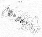
- FIG. 3 is an exploded perspective view of the driving wheel assembly shown in FIG. 2
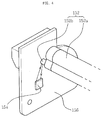
- FIG. 4 is a perspective view illustrating a sensing body and a sensed body extracted from the driving wheel assembly shown in FIG. 2 .
- the driving wheel assembly 100a includes a housing 110, the driving wheel 120 driving the main body 10, a driving motor 130 connected to one side of the housing 110 and rotating the driving wheel 120, a rotary member 101 connected to the housing 110 to be rotatable around a rotation shaft 132 of the driving motor 130, and a sensing unit 150 detecting displacement of the driving wheel 120.
- the housing 110 includes an accommodation part 112 accommodating the driving wheel 120 and the rotary member 101, a first connection hole 114 to which the driving motor 130 is connected, a first connection protrusion 116 connected to the rotary member 101, and a support rib 118 supporting one end of a compression coil spring 170.
- the lower portion of the accommodation part 112 is opened such that the rotary member 101 connected to the housing 110 and the driving wheel 120 connected to the rotary member 101 may move upwards and downwards according to the kind and state of a floor surface of the space to be cleaned.
- the first connection hole 114 is formed on one side surface 110b of the housing 110, and allows the rotation shaft 132 of the driving motor 130 to be connected to the rotary member 101 within the housing 110.
- the first connection protrusion 116 protrudes from the inner plane of the other side surface 110a opposite the side surface 110b of the housing 110, to which the driving motor 130 is connected, to the inside of the housing 110 by a designated length.
- An accommodation hole 116a rotatably accommodating a second connection protrusion 146 of the rotary member 101 to allow the rotary member 101 to be rotated around the first connection protrusion 116 is provided at the center of the first connection protrusion 116.
- the first connection protrusion 116 may be disposed coaxially with the first connection hole 114 and the rotation shaft 132 of the driving motor 130 passing through the first connection hole 114.
- the support rib 118 protrudes from the inner plane of the side surface 110b of the housing 110, to which the driving motor 130 is connected, to the inside of the housing 110 by a designated length, and supports one end of the compression coil spring 170 applying pressure to a first unit 140 of the rotary member 101.
- the driving wheel 120 includes a wheel part 122 directly contacting the floor surface of the space to be cleaned to execute traveling of the main body 10, and a driving shaft 124 connected to the first unit 140 of the rotary member 101 under the condition that the driving shaft 124 is fixed to the wheel part 122 to rotate the wheel part 122.
- the driving motor 130 is connected to the outer plane of the side surface 110b of the housing 110 provided with the first connection hole 114, and the rotation shaft 132 of the driving motor 130 passes through the first connection hole 114 and is connected to the first unit 140 within the housing 110. Driving force of the driving motor 130 is transmitted to the driving shaft 124 through the rotation shaft 132 and power transmission gears 144 connected to the rotation shaft 132, thus rotating the driving wheel 120.
- the first unit 140 includes a female case 142, the power transmission gears 144 engaged with each other and rotatably disposed within the female case 142, and the second connection protrusion 146 connecting the first unit 140 to the housing 110.
- the female case 142 rotatably supports the power transmission gears 144 disposed therein.
- the power transmission gears 144 are rotatably supported by the female case 142 under the condition that they are engaged with each other, and connect the rotation shaft 132 of the driving motor 130 and the driving shaft 124 of the driving wheel 120 to transmit driving force of the driving motor 130 to the driving shaft 124.
- the rotation shaft 132 may pass through a second connection hole 141 formed on one side surface 142b of the female case 142 and be connected to one of the power transmission gears 144, and the driving shaft 124 may pass through a third connection hole 147 formed on the other side surface 142a of the female case 142 and be connected to one of the remaining power transmission gears 44 which are not connected to the rotation shaft 132.
- the second connection protrusion 146 protrudes from the side surface 142a of the female case 142 in a direction towards the first connection protrusion 116 by a designated length, and is rotatably connected to the accommodation hole 116a formed on the first connection protrusion 116.
- a second unit 160 rotated around the rotation shaft 132 of the driving motor 130 together with the first unit 140 is provided at one side of the female case 142.
- the second unit 160 may be formed integrally with the first unit 140.
- the first unit 140 is rotatably connected to the housing 110 through the second connection protrusion 146, and is elastically supported by the housing 110 by the second unit 160 and the compression coil spring 170.
- the sensing unit 150 detecting displacement of the driving wheel 120 includes a sensed body 152 provided on the first unit 140, a sensing body 154 sensing the sensed body 152, and a bracket 156 fixing the sensing body 154 to the housing 110.
- the sensed body 152 includes a protruding rib 152a protruding from the side surface 142b of the female case 142 in a direction towards the side surface 110b of the housing 110, and a magnet 152b connected to one end of the protruding rib 152a.
- a driving motor accommodation part 111 accommodating the driving motor 130 is provided at one side of the housing 110, and the bracket 156 supporting and fixing the sensing body 156 is connected to the driving motor accommodation part 111.
- the sensing body 154 is fixed to one side of the bracket 156, senses a separation distance with the sensed body 152 through magnetic interaction with the magnet 152b moving together with the first unit 140 within the driving motor accommodation part 111, and converts the sensed separation distance with the sensed body 152 into a standardized parameter, such as voltage, to detect displacement of the driving wheel 120.
- FIGS. 5A and 5B are views illustrating operating states of the driving wheel according to a change of a floor surface.
- FIG. 5A illustrates the operating state of the driving wheel when the robot cleaner main body travels about a hard floor surface
- FIG. 5B illustrates the operating state of the driving wheel when the robot cleaner main body travels about a soft floor surface, such as a carpet, for example.
- the compression coil spring 170 is accommodated in an accommodation part 182 formed by the first unit 140, the second unit 160 and the support rib 118, and applies pressure to the second unit 160.
- the compression coil spring 170 includes a fixed terminal 172 which is fixed by contact with a first support surface 118a provided on the support rib 118, and a pressing terminal 174 which presses the second unit 160 by contact with a second support surface 160a of the second unit 160.
- a fixed point P2 is formed on the first support surface 118a contacting the fixed terminal 172, and a pressing point P1 is formed on the second support surface 160a contacting the pressing terminal 174.
- the compression coil spring 170 in a compressed state is accommodated in the accommodation part 182 and applies pressure to the second unit 160 in the tangential direction of a trajectory T formed by the rotation shaft 132 of the driving motor 130 and the pressing point P1 during the rotating process of the second unit 160, and pressure applied to the second unit 160 by the compression coil spring 170 is transmitted to the driving wheel 120 contacting the floor surface through the first unit 140.
- the compression coil spring 170 is disposed at a position opposite to the driving wheel 120 with respect to a first straight line L1 extending from the floor surface which the driving wheel 120 contacts in the vertical direction and passing through the rotation shaft 132 of the driving motor 130. Further, the compression coil spring 170 is disposed at a position opposite to the driving wheel 120 with respect to a third straight line L3 perpendicular to a second straight line L2 connecting a first rotation point C1 around which the first unit 140 is rotated and a second rotation point C2 around which the driving wheel 120 rotatably connected to the first unit 140 is rotated, and is disposed at a position closer to the rotation shaft 132 of the driving motor 130 than the driving wheel 120.
- the second unit 160 protrudes from one side of the first unit 140 where a fourth straight line L4 connecting the first rotation point C1 and the pressing point P1 and the first unit 140 meet, in the radial direction of the trajectory T formed during the rotating process of the pressing point P1, and includes the second support surface 160a contacting the pressing terminal 174 of the compression coil spring 170.
- the pressing point P1 is formed on the second support surface 160a contacting the pressing terminal 174, as described above, and the distance between the pressing point P1 and the first rotation point C1 is shorter than the distance between the first rotation point C1 and the second rotation point C2.
- the support rib 118 protruding from the inner plane of the side surface 110b of the housing 110 adjacent to the first rotation point C1 to the inside of the housing 110, and includes the first support surface 118a contacting the fixed terminal 172 of the compression coil spring 170.
- the fixed point P2 is formed on the first support surface 118a contacting the fixed terminal 172.
- the second unit 160 and the support rib 118 are disposed in a direction opposite to the driving wheel 120 and the second rotation point C2 with respect to the first straight line L1 and the third straight line L3.
- a length change D2 of the compression coil spring 170 is smaller than a displacement D1 of the driving wheel 120 according to the material or state of the floor surface. Because a change of pressure applied to the driving wheel 120 according to the displacement of the driving wheel 120 is as small as the length change of the compression coil spring 170, the main body 10 of the robot cleaner 1 may stably travel.
- a robot cleaner 1 having a compact size may be designed.
- a driving wheel assembly and a robot cleaner having the same stably apply pressure to a driving wheel regardless of displacement of the driving wheel generated according to various states and conditions of floor surfaces, and thus traveling performance of the robot cleaner may be improved.
- a space within a robot cleaner main body occupied by a structure to apply pressure to the driving wheel is reduced, and thus the robot cleaner having a compact size may be designed.
Landscapes
- Engineering & Computer Science (AREA)
- Mechanical Engineering (AREA)
- Electric Suction Cleaners (AREA)
- Electric Vacuum Cleaner (AREA)
Description
- The following description relates to a driving wheel assembly which drives a robot cleaner, and a robot cleaner having the same.
- In general, a robot cleaner is an apparatus which intakes foreign substances, such as dust, from a floor surface to clean a region to be cleaned while autonomously travelling about the region to be cleaned without manipulation by a user.
- Such a robot cleaner includes driving wheels to drive a robot cleaner main body, and the driving wheels drive the robot cleaner main body using frictional force generated between the driving wheels and the floor surface contacting the driving wheels.
- In order for the robot cleaner to have consistent traveling performance in various floor conditions, such as a hard floor, or a carpet, for example, frictional force generated between the driving wheels and the floor surface contacting the driving wheels needs to be consistently maintained regardless of the state or condition of the floor surface. For this purpose, applying pressure to the driving wheels in a direction towards the floor surface is required.
- Conventionally, a tension coil spring is used to apply pressure to the driving wheel in the direction towards the floor surface. However, the tension coil spring may cause a wide range of applied pressure to the driving wheel according to a displacement of the driving wheel. Furthermore, in order to reduce such range of applied pressure, the length of the tension coil spring is increased. Consequently, an installation space for installing the tension coil spring is increased.
- A robot cleaner is already known e.g. from
FR-A-2 856 622 - Therefore, the following description relates to a driving wheel assembly having an improved structure which stably travels regardless of the state and condition of a floor surface, and a robot cleaner having the same. The driving wheel assembly includes a structure where a change in length of a compression coil spring is smaller than a corresponding displacement of a driving wheel. Therefore, a compact-sized robot cleaner with improved mobility on various types of floor surfaces may be designed.
- Additional aspects of the invention will be set forth in part in the description which follows and, in part, will be obvious from the description, or may be learned by practice of the invention.
- In accordance with one aspect, a robot cleaner includes a main body and a driving wheel assembly, including a driving wheel to drive the main body, a housing, a driving motor connected to one side of the housing to generate rotary force to rotate the driving wheel, a rotary member with rotation around a rotation shaft of the driving motor, where the rotary member includes a first unit to which the driving wheel is connected and a second unit disposed at a position opposite to the driving wheel with respect to the rotation shaft of the driving motor, and a compression coil spring disposed between the housing and the second unit to apply pressure to the second unit, where a distance between a contact point where the compression coil spring and the second unit contact and the rotation shaft of the driving motor is shorter than a distance between a rotation shaft of the driving wheel and the rotation shaft of the driving motor.
- The compression coil spring may apply pressure to the second unit in the tangential direction of a trajectory formed by the rotation shaft of the driving motor and the second unit during a process of rotating the rotary member.
- The compression coil spring and driving wheel may be disposed at positions on opposite sides of the rotation shaft of the driving motor.
- The compression coil spring may be disposed at a position opposite to the driving wheel with respect to a first straight line passing through a first rotation point around which the first unit is rotated and perpendicular to a second straight line connecting the first rotation point around which the first unit is rotated and a second rotation point around which the driving wheel rotatably connected to the first unit is rotated.
- A pressing point may be formed at a position where the compression coil spring and the second unit to which the compression coil spring applies pressure contact, and the second unit may protrude from one side of the first unit where a third straight line connecting a first rotation point around which the first unit is rotated and the pressing point and the first unit meet, in the radial direction of a trajectory formed during a process of rotating the pressing point.
- A distance between the pressing point and the first rotation point may be shorter than a distance between the first rotation point and a second point around which the driving wheel rotatably connected to the first unit is rotated.
- The driving wheel assembly may further include a support rib protruding from one side of the housing adjacent to the rotation shaft of the driving motor to the inside of the housing and supporting one end of the compression coil spring.
- The first unit, the second unit, and the support rib may form an accommodation part accommodating the compression coil spring.
- The first unit may include power transmission gears transmitting rotary force of the driving motor to the driving wheel.
- In accordance with another aspect, a robot cleaner includes a main body and a driving wheel assembly to drive the main body, wherein the driving wheel assembly includes a housing, a driving motor connected to one side of the housing, a rotary member including a first unit connected to the housing to be rotated around a rotation shaft of the driving motor, and a second unit protruding from one side of the first unit, a driving wheel rotatably connected to the first unit, and a compression coil spring disposed between a support rib protruding from one side of the housing adjacent to the rotation shaft of the driving motor to the inside of the housing and the second unit, and applying pressure to the second unit in the tangential direction of a trajectory formed by the rotation shaft of the driving motor and the second unit during a process of rotating the rotary member.
- The compression coil spring may be disposed closer to the rotation shaft of the driving motor than the driving wheel.
- The compression coil spring may include a fixed terminal contacting the support rib and a pressing terminal contacting the second unit and applying pressure to the second unit.
- The support rib may include a first support surface supporting the fixed terminal, and the second unit may include a second support surface supporting the pressing terminal.
- The compression coil spring may be disposed at a position opposite to the driving wheel with respect to a first straight line passing through a first rotation point around which the first unit is rotated and perpendicular to a second straight line connecting the first rotation point around which the first unit is rotated and a second rotation point around which the driving wheel is rotated.
- A pressing point may be formed at a position where the pressing terminal and the second unit contact, and the second unit may protrude from one side of the first unit where a third straight line connecting a first rotation point around which the first unit is rotated and the pressing point and the first unit meet, in the radial direction of a trajectory formed during a process of rotating the pressing point.
- The first unit may include power transmission gears transmitting rotary force of the driving motor to the driving wheel.
- In accordance with a further aspect, a driving wheel assembly mounted on a main body of a robot cleaner to drive the robot cleaner includes a housing, a driving motor connected to one side of the housing, a first unit connected to the housing to be rotated around a rotation shaft of the driving motor, and a second unit protruding from one side of the first unit, a driving wheel rotatably connected to the first unit, and at least one compression coil spring disposed at a position opposite to the driving wheel with respect to a straight line passing through the rotation shaft of the driving motor and applying pressure to the second unit in the tangential direction of a trajectory formed by the rotation shaft of the driving motor and the second unit during a process of rotating the first unit.
- In accordance with another aspect, a driving wheel assembly includes a driving motor including a motor rotation shaft; a connecting assembly connected to and rotating around the motor rotation shaft; a driving wheel comprising a wheel rotation shaft, and disposed at a first end of the connecting assembly; and a coil spring disposed at a position to apply tangential pressure to a second end of the connecting assembly along a direction of rotation, where the first end and the second end of the connecting assembly are disposed on opposite sides of the motor rotation shaft, and a rotation of the connecting assembly results in a greater displacement of the driving wheel rotation shaft than a corresponding change in length of the coil spring.
- These and/or other aspects of the invention will become apparent and more readily appreciated from the following description of the embodiments, taken in conjunction with the accompanying drawings of which:
-
FIG. 1 is a perspective view illustrating the configuration of a robot cleaner in accordance with one embodiment; -
FIG. 2 is a perspective view illustrating a driving wheel assembly in accordance with the embodiment, extracted fromFIG. 1 ; -
FIG. 3 is an exploded perspective view of the driving wheel assembly shown inFIG. 2 ; -
FIG. 4 is a perspective view illustrating a sensing body and a sensed body extracted from the driving wheel assembly shown inFIG. 2 ; and -
FIGS. 5A and5B are views illustrating operating states of a driving wheel according to change of a floor surface. - Reference will now be made in detail to the embodiments of the present invention, examples of which are illustrated in the accompanying drawings, wherein like reference numerals refer to like elements throughout.
-
FIG. 1 is a perspective view illustrating the configuration of a robot cleaner in accordance with one embodiment. - As shown in
FIG. 1 , therobot cleaner 1 includes amain body 10 forming the external appearance of therobot cleaner 1, acover 20 covering the upper portion of themain body 10, abrush unit 30 sweeping or scattering dust off a space to be cleaned, a power unit 40 supplying driving power to drive themain body 10, anddriving wheel assemblies main body 10. - The
main body 10 forms the external appearance of therobot cleaner 1 and supports various parts installed within themain body 10. - The
cover 20 includes a transmittingwindow 25 transmitting light generated from an upper camera unit (not shown) to photograph an upper image perpendicular to the traveling direction of themain body 10. - The
brush unit 30 includes a main brush 35 mounted at an inlet (not shown) formed at the lower portion of themain body 10, a main brush motor (not shown) rotating the main brush 35, and a dust case 38 collecting foreign substances, such as dust gathered by the main brush 35. - The main brush 35 sweeps or scatters dust off a floor surface under the
main body 10, thereby improving dust suction efficiency. Such a main brush 35 has a drum shape, and includes a roller and brush. Thebrush unit 30 may further include side brushes (not shown) disposed at both sides of the main brush 35 to sweep dust off a region which the main brush 35 may not approach to improve cleaning efficiency. - The power unit 40 includes
driving motors 130 rotatingdriving wheels 120, and a battery 42 electrically connected to the main brush motor (not shown) rotating the main brush 35 and respective driving units driving themain body 10 and supplying driving power. - The battery 42 is a second battery which may be rechargeable, and may be charged with power supplied from a docking station (not shown) if the
main body 10 completes a cleaning process and is then connected to the docking station (not shown). - The
driving wheel assemblies main body 10, and allow themain body 10 to execute moving operations, such as forward movement, backward movement, or rotation, for example, during the cleaning process of the main body. Hereinafter, thedriving wheel assembly 100a located at the right side in the forward movement direction of themain body 10 will be exemplarily described, and the following description may be applied to thedriving wheel assembly 100b located at the left side in the forward movement direction of themain body 10 unless mentioned otherwise. -
FIG. 2 is a perspective view illustrating a driving wheel assembly in accordance with the embodiment extracted fromFIG. 1 ,FIG. 3 is an exploded perspective view of the driving wheel assembly shown inFIG. 2 , andFIG. 4 is a perspective view illustrating a sensing body and a sensed body extracted from the driving wheel assembly shown inFIG. 2 . - As shown in
FIGS. 2 to 4 , thedriving wheel assembly 100a includes ahousing 110, thedriving wheel 120 driving themain body 10, adriving motor 130 connected to one side of thehousing 110 and rotating thedriving wheel 120, arotary member 101 connected to thehousing 110 to be rotatable around a rotation shaft 132 of thedriving motor 130, and asensing unit 150 detecting displacement of thedriving wheel 120. - The
housing 110 includes an accommodation part 112 accommodating thedriving wheel 120 and therotary member 101, a first connection hole 114 to which the drivingmotor 130 is connected, a first connection protrusion 116 connected to therotary member 101, and asupport rib 118 supporting one end of acompression coil spring 170. - The lower portion of the accommodation part 112 is opened such that the
rotary member 101 connected to thehousing 110 and thedriving wheel 120 connected to therotary member 101 may move upwards and downwards according to the kind and state of a floor surface of the space to be cleaned. - The first connection hole 114 is formed on one side surface 110b of the
housing 110, and allows the rotation shaft 132 of the drivingmotor 130 to be connected to therotary member 101 within thehousing 110. - The first connection protrusion 116 protrudes from the inner plane of the other side surface 110a opposite the side surface 110b of the
housing 110, to which the drivingmotor 130 is connected, to the inside of thehousing 110 by a designated length. An accommodation hole 116a rotatably accommodating asecond connection protrusion 146 of therotary member 101 to allow therotary member 101 to be rotated around the first connection protrusion 116 is provided at the center of the first connection protrusion 116. Further, the first connection protrusion 116 may be disposed coaxially with the first connection hole 114 and the rotation shaft 132 of the drivingmotor 130 passing through the first connection hole 114. - The
support rib 118 protrudes from the inner plane of the side surface 110b of thehousing 110, to which the drivingmotor 130 is connected, to the inside of thehousing 110 by a designated length, and supports one end of thecompression coil spring 170 applying pressure to afirst unit 140 of therotary member 101. - The
driving wheel 120 includes a wheel part 122 directly contacting the floor surface of the space to be cleaned to execute traveling of themain body 10, and a drivingshaft 124 connected to thefirst unit 140 of therotary member 101 under the condition that the drivingshaft 124 is fixed to the wheel part 122 to rotate the wheel part 122. - The driving
motor 130 is connected to the outer plane of the side surface 110b of thehousing 110 provided with the first connection hole 114, and the rotation shaft 132 of the drivingmotor 130 passes through the first connection hole 114 and is connected to thefirst unit 140 within thehousing 110. Driving force of the drivingmotor 130 is transmitted to the drivingshaft 124 through the rotation shaft 132 and power transmission gears 144 connected to the rotation shaft 132, thus rotating thedriving wheel 120. - The
first unit 140 includes a female case 142, the power transmission gears 144 engaged with each other and rotatably disposed within the female case 142, and thesecond connection protrusion 146 connecting thefirst unit 140 to thehousing 110. - The female case 142 rotatably supports the power transmission gears 144 disposed therein.
- The power transmission gears 144 are rotatably supported by the female case 142 under the condition that they are engaged with each other, and connect the rotation shaft 132 of the driving
motor 130 and the drivingshaft 124 of thedriving wheel 120 to transmit driving force of the drivingmotor 130 to the drivingshaft 124. The rotation shaft 132 may pass through a second connection hole 141 formed on one side surface 142b of the female case 142 and be connected to one of the power transmission gears 144, and the drivingshaft 124 may pass through a third connection hole 147 formed on the other side surface 142a of the female case 142 and be connected to one of the remaining power transmission gears 44 which are not connected to the rotation shaft 132. - The
second connection protrusion 146 protrudes from the side surface 142a of the female case 142 in a direction towards the first connection protrusion 116 by a designated length, and is rotatably connected to the accommodation hole 116a formed on the first connection protrusion 116. - A
second unit 160 rotated around the rotation shaft 132 of the drivingmotor 130 together with thefirst unit 140 is provided at one side of the female case 142. Thesecond unit 160 may be formed integrally with thefirst unit 140. - The
first unit 140 is rotatably connected to thehousing 110 through thesecond connection protrusion 146, and is elastically supported by thehousing 110 by thesecond unit 160 and thecompression coil spring 170. - The
sensing unit 150 detecting displacement of thedriving wheel 120 includes a sensedbody 152 provided on thefirst unit 140, asensing body 154 sensing the sensedbody 152, and abracket 156 fixing thesensing body 154 to thehousing 110. - The sensed
body 152 includes a protrudingrib 152a protruding from the side surface 142b of the female case 142 in a direction towards the side surface 110b of thehousing 110, and amagnet 152b connected to one end of the protrudingrib 152a. - A driving motor accommodation part 111 accommodating the driving
motor 130 is provided at one side of thehousing 110, and thebracket 156 supporting and fixing thesensing body 156 is connected to the driving motor accommodation part 111. - The
sensing body 154 is fixed to one side of thebracket 156, senses a separation distance with the sensedbody 152 through magnetic interaction with themagnet 152b moving together with thefirst unit 140 within the driving motor accommodation part 111, and converts the sensed separation distance with the sensedbody 152 into a standardized parameter, such as voltage, to detect displacement of thedriving wheel 120. - Hereinafter, the structure and principle of applying pressure to the
driving wheel 120 driving therobot cleaner 1 will be described in detail. -
FIGS. 5A and5B are views illustrating operating states of the driving wheel according to a change of a floor surface.FIG. 5A illustrates the operating state of the driving wheel when the robot cleaner main body travels about a hard floor surface, andFIG. 5B illustrates the operating state of the driving wheel when the robot cleaner main body travels about a soft floor surface, such as a carpet, for example. - As shown in
FIGS. 2 to 5B , thecompression coil spring 170 is accommodated in anaccommodation part 182 formed by thefirst unit 140, thesecond unit 160 and thesupport rib 118, and applies pressure to thesecond unit 160. - The
compression coil spring 170 includes a fixed terminal 172 which is fixed by contact with afirst support surface 118a provided on thesupport rib 118, and apressing terminal 174 which presses thesecond unit 160 by contact with a second support surface 160a of thesecond unit 160. A fixed point P2 is formed on thefirst support surface 118a contacting the fixed terminal 172, and a pressing point P1 is formed on the second support surface 160a contacting thepressing terminal 174. - The
compression coil spring 170 in a compressed state is accommodated in theaccommodation part 182 and applies pressure to thesecond unit 160 in the tangential direction of a trajectory T formed by the rotation shaft 132 of the drivingmotor 130 and the pressing point P1 during the rotating process of thesecond unit 160, and pressure applied to thesecond unit 160 by thecompression coil spring 170 is transmitted to thedriving wheel 120 contacting the floor surface through thefirst unit 140. - The
compression coil spring 170 is disposed at a position opposite to thedriving wheel 120 with respect to a first straight line L1 extending from the floor surface which thedriving wheel 120 contacts in the vertical direction and passing through the rotation shaft 132 of the drivingmotor 130. Further, thecompression coil spring 170 is disposed at a position opposite to thedriving wheel 120 with respect to a third straight line L3 perpendicular to a second straight line L2 connecting a first rotation point C1 around which thefirst unit 140 is rotated and a second rotation point C2 around which thedriving wheel 120 rotatably connected to thefirst unit 140 is rotated, and is disposed at a position closer to the rotation shaft 132 of the drivingmotor 130 than thedriving wheel 120. - The
second unit 160 protrudes from one side of thefirst unit 140 where a fourth straight line L4 connecting the first rotation point C1 and the pressing point P1 and thefirst unit 140 meet, in the radial direction of the trajectory T formed during the rotating process of the pressing point P1, and includes the second support surface 160a contacting thepressing terminal 174 of thecompression coil spring 170. - The pressing point P1 is formed on the second support surface 160a contacting the
pressing terminal 174, as described above, and the distance between the pressing point P1 and the first rotation point C1 is shorter than the distance between the first rotation point C1 and the second rotation point C2. - The
support rib 118 protruding from the inner plane of the side surface 110b of thehousing 110 adjacent to the first rotation point C1 to the inside of thehousing 110, and includes thefirst support surface 118a contacting the fixed terminal 172 of thecompression coil spring 170. The fixed point P2 is formed on thefirst support surface 118a contacting the fixed terminal 172. - The
second unit 160 and thesupport rib 118 are disposed in a direction opposite to thedriving wheel 120 and the second rotation point C2 with respect to the first straight line L1 and the third straight line L3. - Due to such a structure, as shown in
FIGS. 5A and5B , a length change D2 of thecompression coil spring 170 is smaller than a displacement D1 of thedriving wheel 120 according to the material or state of the floor surface. Because a change of pressure applied to thedriving wheel 120 according to the displacement of thedriving wheel 120 is as small as the length change of thecompression coil spring 170, themain body 10 of therobot cleaner 1 may stably travel. Further, because a space in the accommodation part 112 in thehousing 110, occupied by a structure applying pressure to thedriving wheel 120, i.e., thefirst unit 140, thesecond unit 160, and thesupport rib 118, is small and the length of thecompression coil spring 170 is minimized, arobot cleaner 1 having a compact size may be designed. - As is apparent from the above description, a driving wheel assembly and a robot cleaner having the same stably apply pressure to a driving wheel regardless of displacement of the driving wheel generated according to various states and conditions of floor surfaces, and thus traveling performance of the robot cleaner may be improved.
- Further, a space within a robot cleaner main body occupied by a structure to apply pressure to the driving wheel is reduced, and thus the robot cleaner having a compact size may be designed.
- Although a few embodiments of the present invention have been shown and described, it would be appreciated by those skilled in the art that changes may be made in these embodiments without departing from the principles of the invention, the scope of which is defined in the claims.
Claims (9)
- A robot cleaner (1) comprising:a main body (10); anda driving wheel assembly (100a, b), comprising:a driving wheel (120) to drive the main body (10);a housing (110);a driving motor (130) connected to one side of the housing (110) to generate rotary force to rotate the driving wheel;a rotary member (101) with rotation around a rotation shaft (132) of the driving motor (130), wherein the rotary member (101) comprises a first unit (140) to which the driving wheel (120) is connected and a second unit (160) disposed at a position opposite to the driving wheel with respect to the rotation shaft of the driving motor; anda compression coil spring (170) disposed between the housing (110) and the second unit (160) to apply pressure to the second unit,wherein a distance between a contact point (P1) where the compression coil spring (170) and the second unit (160) contact and the rotation shaft (132) of the driving motor is shorter than a distance between a rotation shaft (124) of the driving wheel (120) and the rotation shaft (132) of the driving motor (130).
- The robot cleaner according to claim 1, wherein the compression coil spring (170) applies pressure to the second unit (160) in the tangential direction of a trajectory (T) formed by the rotation shaft (132) of the driving motor (130) and the second unit (160) during a process of rotating the rotary member (101).
- The robot cleaner according to claim 2, wherein the compression coil spring (170) and driving wheel (120) are disposed at positions on opposite sides of the rotation shaft (132) of the driving motor (130).
- The robot cleaner according to claim 1, wherein the compression coil spring (170) is disposed at a position opposite to the driving wheel (120) with respect to a first straight line (L1) passing through a first rotation point (C1) around which the first unit (140) is rotated and perpendicular to a second straight line (L2) connecting the first rotation point (C1) around which the first unit (140) is rotated and a second rotation point (C2) around which the driving wheel (120) rotatably connected to the first unit is rotated.
- The robot cleaner according to claim 1, wherein:a pressing point (P1) is formed at a position where the compression coil spring (170) and the second unit (160) to which the compression coil spring applies pressures contact; andthe second unit (160) protrudes from one side of the first unit (140) where a third straight line (L3) connecting a first rotation point (C1) around which the first unit (140) is rotated and the pressing point (P1) and the first unit meet (140), in the radial direction of a trajectory formed during a process of rotating the pressing point.
- The robot cleaner according to claim 5, wherein a distance between the pressing point (P1) and the first rotation point (C1) is shorter than a distance between the first rotation point (C1) and a second rotation point (C2) around which the driving wheel (120) rotatably connected to the first unit (140) is rotated.
- The robot cleaner according to claim 1, wherein the driving wheel assembly (100a, b) further comprises a support rib (118) protruding from one side of the housing (110) adjacent to the rotation shaft (132) of the driving motor (130) to the inside of the housing and supporting one end of the compression coil spring (170).
- The robot cleaner according to claim 7, wherein the first unit (140), the second unit (160), and the support rib (118) form an accommodation part (182) accommodating the compression coil spring (170).
- The robot cleaner according to claim 1, wherein the first unit (140) comprises power transmission gears (144) transmitting rotary force of the driving motor (130) to the driving wheel (120).
Priority Applications (1)
| Application Number | Priority Date | Filing Date | Title |
|---|---|---|---|
| EP15160798.3A EP2912982B1 (en) | 2011-09-01 | 2012-08-17 | Driving wheel assembly |
Applications Claiming Priority (2)
| Application Number | Priority Date | Filing Date | Title |
|---|---|---|---|
| US201161530019P | 2011-09-01 | 2011-09-01 | |
| KR1020110101418A KR101778542B1 (en) | 2011-09-01 | 2011-10-05 | Driving wheel assembly and robot cleaner having the same |
Related Child Applications (1)
| Application Number | Title | Priority Date | Filing Date |
|---|---|---|---|
| EP15160798.3A Division EP2912982B1 (en) | 2011-09-01 | 2012-08-17 | Driving wheel assembly |
Publications (2)
| Publication Number | Publication Date |
|---|---|
| EP2570064A1 EP2570064A1 (en) | 2013-03-20 |
| EP2570064B1 true EP2570064B1 (en) | 2015-04-01 |
Family
ID=46704504
Family Applications (1)
| Application Number | Title | Priority Date | Filing Date |
|---|---|---|---|
| EP12180884.4A Active EP2570064B1 (en) | 2011-09-01 | 2012-08-17 | Driving wheel assembly and robot cleaner having the same |
Country Status (4)
| Country | Link |
|---|---|
| US (1) | US9241602B2 (en) |
| EP (1) | EP2570064B1 (en) |
| JP (1) | JP2013052239A (en) |
| CN (1) | CN102961086B (en) |
Families Citing this family (20)
| Publication number | Priority date | Publication date | Assignee | Title |
|---|---|---|---|---|
| KR101523980B1 (en) * | 2011-01-18 | 2015-06-01 | 삼성전자 주식회사 | Autonomous cleaning device |
| KR101970584B1 (en) | 2011-09-01 | 2019-08-27 | 삼성전자주식회사 | Cleaning system and maintenance station thereof |
| EP2570064B1 (en) * | 2011-09-01 | 2015-04-01 | Samsung Electronics Co., Ltd. | Driving wheel assembly and robot cleaner having the same |
| GB2494444B (en) * | 2011-09-09 | 2013-12-25 | Dyson Technology Ltd | Drive arrangement for a mobile robot |
| GB2494443B (en) | 2011-09-09 | 2013-08-07 | Dyson Technology Ltd | Autonomous surface treating appliance |
| WO2016096027A1 (en) * | 2014-12-18 | 2016-06-23 | Aktiebolaget Electrolux | Autonomous cleaning apparatus |
| JP6609410B2 (en) * | 2015-01-08 | 2019-11-20 | シャープ株式会社 | Self-propelled electronic device |
| JP6670544B2 (en) * | 2015-01-08 | 2020-03-25 | シャープ株式会社 | Self-propelled electronic equipment |
| KR102320199B1 (en) * | 2015-04-13 | 2021-11-02 | 삼성전자주식회사 | Driving unit and robot cleaner having the same |
| KR102376774B1 (en) * | 2015-11-20 | 2022-03-21 | 삼성전자주식회사 | Wheel assembly and robot cleaner having the same |
| WO2017194102A1 (en) * | 2016-05-11 | 2017-11-16 | Aktiebolaget Electrolux | Robotic cleaning device |
| KR101842129B1 (en) * | 2016-05-17 | 2018-03-26 | 엘지전자 주식회사 | Cleaner |
| CN106137059A (en) * | 2016-07-05 | 2016-11-23 | 蒙泽喜 | A kind of intelligent cleaning equipment using wireless remote control technology |
| US10301837B2 (en) | 2016-11-04 | 2019-05-28 | Aqua Products, Inc. | Drive module for submersible autonomous vehicle |
| US9902477B1 (en) | 2016-11-04 | 2018-02-27 | Aqua Products, Inc. | Drive module for submersible autonomous vehicle |
| CN107440614B (en) | 2017-08-07 | 2019-12-20 | 江苏美的清洁电器股份有限公司 | Vacuum cleaner |
| CN111315587A (en) * | 2017-11-16 | 2020-06-19 | 夏普株式会社 | Wheel support structure for self-propelled electronic device |
| CN108797485A (en) * | 2018-06-27 | 2018-11-13 | 杨扬 | Clean robot with flexible drive wheel assembly |
| CN109008831A (en) * | 2018-09-30 | 2018-12-18 | 江苏美的清洁电器股份有限公司 | The roller gearing of sweeping robot and sweeping robot with it |
| CN111227731B (en) * | 2020-03-20 | 2024-04-19 | 广东金力智能传动技术股份有限公司 | Robot integrated walking module and control method thereof |
Family Cites Families (42)
| Publication number | Priority date | Publication date | Assignee | Title |
|---|---|---|---|---|
| US3380546A (en) * | 1966-02-14 | 1968-04-30 | Rodney R. Rabjohn | Traction drive for small vehicles |
| US3827103A (en) * | 1970-05-19 | 1974-08-06 | Whirlpool Co | Vacuum cleaner |
| US4513472A (en) | 1983-11-07 | 1985-04-30 | Wells R Leon | Height adjustment mechanism |
| NO864109L (en) * | 1985-10-17 | 1987-04-21 | Knepper Hans Reinhard | PROCEDURE FOR AUTOMATIC LINING OF AUTOMATIC FLOOR CLEANING MACHINES AND FLOOR CLEANING MACHINE FOR PERFORMING THE PROCEDURE. |
| US4829442A (en) * | 1986-05-16 | 1989-05-09 | Denning Mobile Robotics, Inc. | Beacon navigation system and method for guiding a vehicle |
| DE3839433C1 (en) * | 1988-11-23 | 1989-10-19 | Carl Hurth Maschinen- Und Zahnradfabrik Gmbh & Co, 8000 Muenchen, De | |
| US4938309A (en) | 1989-06-08 | 1990-07-03 | M.D. Manufacturing, Inc. | Built-in vacuum cleaning system with improved acoustic damping design |
| US6496754B2 (en) * | 2000-11-17 | 2002-12-17 | Samsung Kwangju Electronics Co., Ltd. | Mobile robot and course adjusting method thereof |
| US6604348B2 (en) * | 2001-02-06 | 2003-08-12 | Deere & Company | Mower with engine-driven blade and electrical propulsion |
| SE525970C2 (en) * | 2002-01-22 | 2005-06-07 | Visual Act Scandinavia Ab | A drive unit and a motor-driven vehicle |
| JP3641618B2 (en) | 2002-05-02 | 2005-04-27 | 山崎産業株式会社 | Cleaning tool |
| US20050150519A1 (en) | 2002-07-08 | 2005-07-14 | Alfred Kaercher Gmbh & Co. Kg | Method for operating a floor cleaning system, and floor cleaning system for use of the method |
| KR100538949B1 (en) * | 2003-04-04 | 2005-12-27 | 삼성광주전자 주식회사 | Driving unit for robot cleaner |
| KR100963387B1 (en) | 2003-05-07 | 2010-06-14 | 엘지전자 주식회사 | Wheel assembly for robot vacuum cleaner |
| KR100507926B1 (en) * | 2003-06-30 | 2005-08-17 | 삼성광주전자 주식회사 | Device for driving of robot cleaner |
| KR100518819B1 (en) * | 2003-08-01 | 2005-10-05 | 삼성전자주식회사 | Mobile robot |
| CN100358457C (en) * | 2003-09-28 | 2008-01-02 | 乐金电子(天津)电器有限公司 | Damping and sensing device of intelligent vacuum cleaner |
| EP1672455A4 (en) * | 2003-10-08 | 2007-12-05 | Figla Co Ltd | Self-propelled working robot |
| US7721829B2 (en) * | 2005-11-29 | 2010-05-25 | Samsung Electronics Co., Ltd. | Traveling robot |
| ES2413862T3 (en) * | 2005-12-02 | 2013-07-17 | Irobot Corporation | Modular robot |
| KR100761997B1 (en) * | 2005-12-29 | 2007-09-28 | 에이스로봇 주식회사 | Wheel Assembly for Automatic Robot Cleaner |
| KR20070074146A (en) | 2006-01-06 | 2007-07-12 | 삼성전자주식회사 | Cleaner system |
| KR20070074147A (en) | 2006-01-06 | 2007-07-12 | 삼성전자주식회사 | Cleaner system |
| US8087117B2 (en) | 2006-05-19 | 2012-01-03 | Irobot Corporation | Cleaning robot roller processing |
| KR100779195B1 (en) * | 2006-11-14 | 2007-11-23 | 주식회사 대우일렉트로닉스 | Robot cleaner and suspension module therefor |
| KR100807409B1 (en) * | 2006-12-22 | 2008-02-25 | 주식회사 유진로봇 | A robot cleaner for the weightcenter of construction eccentrically |
| KR100911832B1 (en) * | 2007-05-31 | 2009-08-13 | 주식회사 아모텍 | Slim Type Vacuum Inhaling Apparatus Having High Efficiency and Robot Cleaner Using the Same |
| CN201119841Y (en) * | 2007-07-24 | 2008-09-24 | 方曙光 | Drive wheel apparatus of automatic suction cleaner |
| KR20090028359A (en) * | 2007-09-14 | 2009-03-18 | 삼성광주전자 주식회사 | A wheel-driving assembly for a moving apparatus |
| KR100857540B1 (en) * | 2007-09-27 | 2008-09-08 | (주)컨벡스 | Mobile robot |
| JP4740917B2 (en) | 2007-09-28 | 2011-08-03 | 三菱電機株式会社 | Cleaning device, filter cleaning device and air conditioner |
| CN101664603A (en) * | 2008-09-05 | 2010-03-10 | 鸿富锦精密工业(深圳)有限公司 | Electronic toy |
| US20100125968A1 (en) | 2008-11-26 | 2010-05-27 | Howard Ho | Automated apparatus and equipped trashcan |
| DE102009041728B4 (en) | 2008-12-22 | 2022-07-07 | Vorwerk & Co. Interholding Gmbh | Method for operating a vacuum cleaner and moveable vacuum cleaning device |
| US8774970B2 (en) * | 2009-06-11 | 2014-07-08 | S.C. Johnson & Son, Inc. | Trainable multi-mode floor cleaning device |
| KR101473870B1 (en) | 2009-06-19 | 2014-12-18 | 삼성전자 주식회사 | Cleaning apparatus |
| CN101711659B (en) * | 2009-12-14 | 2012-06-27 | 杭州明强智能科技有限公司 | Dust catcher walking device with adjustable height |
| KR101573742B1 (en) | 2010-10-25 | 2015-12-07 | 삼성전자주식회사 | Autonomous cleaning device |
| KR101523980B1 (en) * | 2011-01-18 | 2015-06-01 | 삼성전자 주식회사 | Autonomous cleaning device |
| JP5958465B2 (en) * | 2011-07-08 | 2016-08-02 | 日本電産株式会社 | Wheel unit |
| KR101311295B1 (en) * | 2011-07-13 | 2013-09-25 | 주식회사 유진로봇 | Wheel assembly for moving robot |
| EP2570064B1 (en) * | 2011-09-01 | 2015-04-01 | Samsung Electronics Co., Ltd. | Driving wheel assembly and robot cleaner having the same |
-
2012
- 2012-08-17 EP EP12180884.4A patent/EP2570064B1/en active Active
- 2012-08-21 US US13/590,274 patent/US9241602B2/en active Active
- 2012-08-30 JP JP2012189712A patent/JP2013052239A/en active Pending
- 2012-09-03 CN CN201210322214.1A patent/CN102961086B/en active Active
Also Published As
| Publication number | Publication date |
|---|---|
| JP2013052239A (en) | 2013-03-21 |
| EP2570064A1 (en) | 2013-03-20 |
| US20130056290A1 (en) | 2013-03-07 |
| CN102961086A (en) | 2013-03-13 |
| US9241602B2 (en) | 2016-01-26 |
| CN102961086B (en) | 2016-12-07 |
Similar Documents
| Publication | Publication Date | Title |
|---|---|---|
| EP2570064B1 (en) | Driving wheel assembly and robot cleaner having the same | |
| EP2912982B1 (en) | Driving wheel assembly | |
| US11882970B2 (en) | Cleaning device and sweeping assembly thereof | |
| KR101812021B1 (en) | Robot cleaner | |
| US9335767B2 (en) | Robot cleaner and control method thereof | |
| US10362921B2 (en) | Cleaner | |
| KR101420972B1 (en) | Electric cleaner | |
| EP2886030B1 (en) | Automatic cleaner | |
| US20140026338A1 (en) | Autonomous cleaning device | |
| EP3000368B1 (en) | Robot cleaner | |
| KR20160138812A (en) | Robot cleaner | |
| US10905301B2 (en) | Cleaner | |
| JP6239944B2 (en) | Self-propelled vacuum cleaner | |
| JPH05269065A (en) | Vacuum cleaner |
Legal Events
| Date | Code | Title | Description |
|---|---|---|---|
| PUAI | Public reference made under article 153(3) epc to a published international application that has entered the european phase |
Free format text: ORIGINAL CODE: 0009012 |
|
| AK | Designated contracting states |
Kind code of ref document: A1 Designated state(s): AL AT BE BG CH CY CZ DE DK EE ES FI FR GB GR HR HU IE IS IT LI LT LU LV MC MK MT NL NO PL PT RO RS SE SI SK SM TR |
|
| AX | Request for extension of the european patent |
Extension state: BA ME |
|
| RIC1 | Information provided on ipc code assigned before grant |
Ipc: A47L 9/00 20060101AFI20130219BHEP |
|
| 17P | Request for examination filed |
Effective date: 20130917 |
|
| RBV | Designated contracting states (corrected) |
Designated state(s): AL AT BE BG CH CY CZ DE DK EE ES FI FR GB GR HR HU IE IS IT LI LT LU LV MC MK MT NL NO PL PT RO RS SE SI SK SM TR |
|
| GRAP | Despatch of communication of intention to grant a patent |
Free format text: ORIGINAL CODE: EPIDOSNIGR1 |
|
| INTG | Intention to grant announced |
Effective date: 20141021 |
|
| GRAS | Grant fee paid |
Free format text: ORIGINAL CODE: EPIDOSNIGR3 |
|
| GRAA | (expected) grant |
Free format text: ORIGINAL CODE: 0009210 |
|
| AK | Designated contracting states |
Kind code of ref document: B1 Designated state(s): AL AT BE BG CH CY CZ DE DK EE ES FI FR GB GR HR HU IE IS IT LI LT LU LV MC MK MT NL NO PL PT RO RS SE SI SK SM TR |
|
| REG | Reference to a national code |
Ref country code: GB Ref legal event code: FG4D |
|
| REG | Reference to a national code |
Ref country code: CH Ref legal event code: EP |
|
| REG | Reference to a national code |
Ref country code: IE Ref legal event code: FG4D |
|
| REG | Reference to a national code |
Ref country code: AT Ref legal event code: REF Ref document number: 718588 Country of ref document: AT Kind code of ref document: T Effective date: 20150515 |
|
| REG | Reference to a national code |
Ref country code: DE Ref legal event code: R096 Ref document number: 602012006282 Country of ref document: DE Effective date: 20150521 |
|
| REG | Reference to a national code |
Ref country code: NL Ref legal event code: VDEP Effective date: 20150401 |
|
| REG | Reference to a national code |
Ref country code: AT Ref legal event code: MK05 Ref document number: 718588 Country of ref document: AT Kind code of ref document: T Effective date: 20150401 |
|
| REG | Reference to a national code |
Ref country code: LT Ref legal event code: MG4D |
|
| PG25 | Lapsed in a contracting state [announced via postgrant information from national office to epo] |
Ref country code: NL Free format text: LAPSE BECAUSE OF FAILURE TO SUBMIT A TRANSLATION OF THE DESCRIPTION OR TO PAY THE FEE WITHIN THE PRESCRIBED TIME-LIMIT Effective date: 20150401 |
|
| PG25 | Lapsed in a contracting state [announced via postgrant information from national office to epo] |
Ref country code: LT Free format text: LAPSE BECAUSE OF FAILURE TO SUBMIT A TRANSLATION OF THE DESCRIPTION OR TO PAY THE FEE WITHIN THE PRESCRIBED TIME-LIMIT Effective date: 20150401 Ref country code: ES Free format text: LAPSE BECAUSE OF FAILURE TO SUBMIT A TRANSLATION OF THE DESCRIPTION OR TO PAY THE FEE WITHIN THE PRESCRIBED TIME-LIMIT Effective date: 20150401 Ref country code: HR Free format text: LAPSE BECAUSE OF FAILURE TO SUBMIT A TRANSLATION OF THE DESCRIPTION OR TO PAY THE FEE WITHIN THE PRESCRIBED TIME-LIMIT Effective date: 20150401 Ref country code: CZ Free format text: LAPSE BECAUSE OF FAILURE TO SUBMIT A TRANSLATION OF THE DESCRIPTION OR TO PAY THE FEE WITHIN THE PRESCRIBED TIME-LIMIT Effective date: 20150401 Ref country code: NO Free format text: LAPSE BECAUSE OF FAILURE TO SUBMIT A TRANSLATION OF THE DESCRIPTION OR TO PAY THE FEE WITHIN THE PRESCRIBED TIME-LIMIT Effective date: 20150701 Ref country code: FI Free format text: LAPSE BECAUSE OF FAILURE TO SUBMIT A TRANSLATION OF THE DESCRIPTION OR TO PAY THE FEE WITHIN THE PRESCRIBED TIME-LIMIT Effective date: 20150401 Ref country code: PT Free format text: LAPSE BECAUSE OF FAILURE TO SUBMIT A TRANSLATION OF THE DESCRIPTION OR TO PAY THE FEE WITHIN THE PRESCRIBED TIME-LIMIT Effective date: 20150803 |
|
| PG25 | Lapsed in a contracting state [announced via postgrant information from national office to epo] |
Ref country code: LV Free format text: LAPSE BECAUSE OF FAILURE TO SUBMIT A TRANSLATION OF THE DESCRIPTION OR TO PAY THE FEE WITHIN THE PRESCRIBED TIME-LIMIT Effective date: 20150401 Ref country code: IS Free format text: LAPSE BECAUSE OF FAILURE TO SUBMIT A TRANSLATION OF THE DESCRIPTION OR TO PAY THE FEE WITHIN THE PRESCRIBED TIME-LIMIT Effective date: 20150801 Ref country code: AT Free format text: LAPSE BECAUSE OF FAILURE TO SUBMIT A TRANSLATION OF THE DESCRIPTION OR TO PAY THE FEE WITHIN THE PRESCRIBED TIME-LIMIT Effective date: 20150401 Ref country code: GR Free format text: LAPSE BECAUSE OF FAILURE TO SUBMIT A TRANSLATION OF THE DESCRIPTION OR TO PAY THE FEE WITHIN THE PRESCRIBED TIME-LIMIT Effective date: 20150702 Ref country code: RS Free format text: LAPSE BECAUSE OF FAILURE TO SUBMIT A TRANSLATION OF THE DESCRIPTION OR TO PAY THE FEE WITHIN THE PRESCRIBED TIME-LIMIT Effective date: 20150401 |
|
| REG | Reference to a national code |
Ref country code: DE Ref legal event code: R097 Ref document number: 602012006282 Country of ref document: DE |
|
| PG25 | Lapsed in a contracting state [announced via postgrant information from national office to epo] |
Ref country code: EE Free format text: LAPSE BECAUSE OF FAILURE TO SUBMIT A TRANSLATION OF THE DESCRIPTION OR TO PAY THE FEE WITHIN THE PRESCRIBED TIME-LIMIT Effective date: 20150401 Ref country code: DK Free format text: LAPSE BECAUSE OF FAILURE TO SUBMIT A TRANSLATION OF THE DESCRIPTION OR TO PAY THE FEE WITHIN THE PRESCRIBED TIME-LIMIT Effective date: 20150401 |
|
| PLBE | No opposition filed within time limit |
Free format text: ORIGINAL CODE: 0009261 |
|
| STAA | Information on the status of an ep patent application or granted ep patent |
Free format text: STATUS: NO OPPOSITION FILED WITHIN TIME LIMIT |
|
| PG25 | Lapsed in a contracting state [announced via postgrant information from national office to epo] |
Ref country code: SK Free format text: LAPSE BECAUSE OF FAILURE TO SUBMIT A TRANSLATION OF THE DESCRIPTION OR TO PAY THE FEE WITHIN THE PRESCRIBED TIME-LIMIT Effective date: 20150401 Ref country code: PL Free format text: LAPSE BECAUSE OF FAILURE TO SUBMIT A TRANSLATION OF THE DESCRIPTION OR TO PAY THE FEE WITHIN THE PRESCRIBED TIME-LIMIT Effective date: 20150401 Ref country code: RO Free format text: LAPSE BECAUSE OF NON-PAYMENT OF DUE FEES Effective date: 20150401 |
|
| 26N | No opposition filed |
Effective date: 20160105 |
|
| PG25 | Lapsed in a contracting state [announced via postgrant information from national office to epo] |
Ref country code: MC Free format text: LAPSE BECAUSE OF FAILURE TO SUBMIT A TRANSLATION OF THE DESCRIPTION OR TO PAY THE FEE WITHIN THE PRESCRIBED TIME-LIMIT Effective date: 20150401 Ref country code: LU Free format text: LAPSE BECAUSE OF FAILURE TO SUBMIT A TRANSLATION OF THE DESCRIPTION OR TO PAY THE FEE WITHIN THE PRESCRIBED TIME-LIMIT Effective date: 20150817 |
|
| REG | Reference to a national code |
Ref country code: CH Ref legal event code: PL |
|
| PG25 | Lapsed in a contracting state [announced via postgrant information from national office to epo] |
Ref country code: CH Free format text: LAPSE BECAUSE OF NON-PAYMENT OF DUE FEES Effective date: 20150831 Ref country code: LI Free format text: LAPSE BECAUSE OF NON-PAYMENT OF DUE FEES Effective date: 20150831 |
|
| PG25 | Lapsed in a contracting state [announced via postgrant information from national office to epo] |
Ref country code: SI Free format text: LAPSE BECAUSE OF FAILURE TO SUBMIT A TRANSLATION OF THE DESCRIPTION OR TO PAY THE FEE WITHIN THE PRESCRIBED TIME-LIMIT Effective date: 20150401 |
|
| REG | Reference to a national code |
Ref country code: IE Ref legal event code: MM4A |
|
| REG | Reference to a national code |
Ref country code: FR Ref legal event code: PLFP Year of fee payment: 5 |
|
| PG25 | Lapsed in a contracting state [announced via postgrant information from national office to epo] |
Ref country code: IE Free format text: LAPSE BECAUSE OF NON-PAYMENT OF DUE FEES Effective date: 20150817 |
|
| PG25 | Lapsed in a contracting state [announced via postgrant information from national office to epo] |
Ref country code: BE Free format text: LAPSE BECAUSE OF FAILURE TO SUBMIT A TRANSLATION OF THE DESCRIPTION OR TO PAY THE FEE WITHIN THE PRESCRIBED TIME-LIMIT Effective date: 20150401 |
|
| PG25 | Lapsed in a contracting state [announced via postgrant information from national office to epo] |
Ref country code: MT Free format text: LAPSE BECAUSE OF FAILURE TO SUBMIT A TRANSLATION OF THE DESCRIPTION OR TO PAY THE FEE WITHIN THE PRESCRIBED TIME-LIMIT Effective date: 20150401 |
|
| PG25 | Lapsed in a contracting state [announced via postgrant information from national office to epo] |
Ref country code: BG Free format text: LAPSE BECAUSE OF FAILURE TO SUBMIT A TRANSLATION OF THE DESCRIPTION OR TO PAY THE FEE WITHIN THE PRESCRIBED TIME-LIMIT Effective date: 20150401 Ref country code: HU Free format text: LAPSE BECAUSE OF FAILURE TO SUBMIT A TRANSLATION OF THE DESCRIPTION OR TO PAY THE FEE WITHIN THE PRESCRIBED TIME-LIMIT; INVALID AB INITIO Effective date: 20120817 Ref country code: SM Free format text: LAPSE BECAUSE OF FAILURE TO SUBMIT A TRANSLATION OF THE DESCRIPTION OR TO PAY THE FEE WITHIN THE PRESCRIBED TIME-LIMIT Effective date: 20150401 |
|
| PG25 | Lapsed in a contracting state [announced via postgrant information from national office to epo] |
Ref country code: SE Free format text: LAPSE BECAUSE OF FAILURE TO SUBMIT A TRANSLATION OF THE DESCRIPTION OR TO PAY THE FEE WITHIN THE PRESCRIBED TIME-LIMIT Effective date: 20150401 Ref country code: CY Free format text: LAPSE BECAUSE OF FAILURE TO SUBMIT A TRANSLATION OF THE DESCRIPTION OR TO PAY THE FEE WITHIN THE PRESCRIBED TIME-LIMIT Effective date: 20150401 |
|
| REG | Reference to a national code |
Ref country code: FR Ref legal event code: PLFP Year of fee payment: 6 |
|
| PG25 | Lapsed in a contracting state [announced via postgrant information from national office to epo] |
Ref country code: TR Free format text: LAPSE BECAUSE OF FAILURE TO SUBMIT A TRANSLATION OF THE DESCRIPTION OR TO PAY THE FEE WITHIN THE PRESCRIBED TIME-LIMIT Effective date: 20150401 |
|
| PG25 | Lapsed in a contracting state [announced via postgrant information from national office to epo] |
Ref country code: MK Free format text: LAPSE BECAUSE OF FAILURE TO SUBMIT A TRANSLATION OF THE DESCRIPTION OR TO PAY THE FEE WITHIN THE PRESCRIBED TIME-LIMIT Effective date: 20150401 |
|
| REG | Reference to a national code |
Ref country code: FR Ref legal event code: PLFP Year of fee payment: 7 |
|
| PG25 | Lapsed in a contracting state [announced via postgrant information from national office to epo] |
Ref country code: AL Free format text: LAPSE BECAUSE OF FAILURE TO SUBMIT A TRANSLATION OF THE DESCRIPTION OR TO PAY THE FEE WITHIN THE PRESCRIBED TIME-LIMIT Effective date: 20150401 |
|
| PGFP | Annual fee paid to national office [announced via postgrant information from national office to epo] |
Ref country code: FR Payment date: 20200722 Year of fee payment: 9 |
|
| PGFP | Annual fee paid to national office [announced via postgrant information from national office to epo] |
Ref country code: IT Payment date: 20200813 Year of fee payment: 9 |
|
| PG25 | Lapsed in a contracting state [announced via postgrant information from national office to epo] |
Ref country code: IT Free format text: LAPSE BECAUSE OF NON-PAYMENT OF DUE FEES Effective date: 20210817 Ref country code: FR Free format text: LAPSE BECAUSE OF NON-PAYMENT OF DUE FEES Effective date: 20210831 |
|
| PGFP | Annual fee paid to national office [announced via postgrant information from national office to epo] |
Ref country code: GB Payment date: 20230720 Year of fee payment: 12 |
|
| PGFP | Annual fee paid to national office [announced via postgrant information from national office to epo] |
Ref country code: DE Payment date: 20230720 Year of fee payment: 12 |