EP3080564B1 - Modulares system zur bestimmung und/oder überwachung einer prozessgrösse eines mediums oder zur bestimmung und/oder überwachung eines vorgegebenen füllstands eines mediums in einem behälter - Google Patents
Modulares system zur bestimmung und/oder überwachung einer prozessgrösse eines mediums oder zur bestimmung und/oder überwachung eines vorgegebenen füllstands eines mediums in einem behälter Download PDFInfo
- Publication number
- EP3080564B1 EP3080564B1 EP14799146.7A EP14799146A EP3080564B1 EP 3080564 B1 EP3080564 B1 EP 3080564B1 EP 14799146 A EP14799146 A EP 14799146A EP 3080564 B1 EP3080564 B1 EP 3080564B1
- Authority
- EP
- European Patent Office
- Prior art keywords
- module
- contact
- modular system
- designed
- sensor module
- Prior art date
- Legal status (The legal status is an assumption and is not a legal conclusion. Google has not performed a legal analysis and makes no representation as to the accuracy of the status listed.)
- Active
Links
Images


Classifications
-
- G—PHYSICS
- G01—MEASURING; TESTING
- G01F—MEASURING VOLUME, VOLUME FLOW, MASS FLOW OR LIQUID LEVEL; METERING BY VOLUME
- G01F23/00—Indicating or measuring liquid level or level of fluent solid material, e.g. indicating in terms of volume or indicating by means of an alarm
- G01F23/22—Indicating or measuring liquid level or level of fluent solid material, e.g. indicating in terms of volume or indicating by means of an alarm by measuring physical variables, other than linear dimensions, pressure or weight, dependent on the level to be measured, e.g. by difference of heat transfer of steam or water
- G01F23/28—Indicating or measuring liquid level or level of fluent solid material, e.g. indicating in terms of volume or indicating by means of an alarm by measuring physical variables, other than linear dimensions, pressure or weight, dependent on the level to be measured, e.g. by difference of heat transfer of steam or water by measuring the variations of parameters of electromagnetic or acoustic waves applied directly to the liquid or fluent solid material
- G01F23/296—Acoustic waves
- G01F23/2966—Acoustic waves making use of acoustical resonance or standing waves
-
- G—PHYSICS
- G01—MEASURING; TESTING
- G01F—MEASURING VOLUME, VOLUME FLOW, MASS FLOW OR LIQUID LEVEL; METERING BY VOLUME
- G01F23/00—Indicating or measuring liquid level or level of fluent solid material, e.g. indicating in terms of volume or indicating by means of an alarm
-
- G—PHYSICS
- G01—MEASURING; TESTING
- G01F—MEASURING VOLUME, VOLUME FLOW, MASS FLOW OR LIQUID LEVEL; METERING BY VOLUME
- G01F23/00—Indicating or measuring liquid level or level of fluent solid material, e.g. indicating in terms of volume or indicating by means of an alarm
- G01F23/22—Indicating or measuring liquid level or level of fluent solid material, e.g. indicating in terms of volume or indicating by means of an alarm by measuring physical variables, other than linear dimensions, pressure or weight, dependent on the level to be measured, e.g. by difference of heat transfer of steam or water
- G01F23/28—Indicating or measuring liquid level or level of fluent solid material, e.g. indicating in terms of volume or indicating by means of an alarm by measuring physical variables, other than linear dimensions, pressure or weight, dependent on the level to be measured, e.g. by difference of heat transfer of steam or water by measuring the variations of parameters of electromagnetic or acoustic waves applied directly to the liquid or fluent solid material
- G01F23/296—Acoustic waves
- G01F23/2966—Acoustic waves making use of acoustical resonance or standing waves
- G01F23/2967—Acoustic waves making use of acoustical resonance or standing waves for discrete levels
-
- G—PHYSICS
- G01—MEASURING; TESTING
- G01F—MEASURING VOLUME, VOLUME FLOW, MASS FLOW OR LIQUID LEVEL; METERING BY VOLUME
- G01F23/00—Indicating or measuring liquid level or level of fluent solid material, e.g. indicating in terms of volume or indicating by means of an alarm
- G01F23/22—Indicating or measuring liquid level or level of fluent solid material, e.g. indicating in terms of volume or indicating by means of an alarm by measuring physical variables, other than linear dimensions, pressure or weight, dependent on the level to be measured, e.g. by difference of heat transfer of steam or water
- G01F23/28—Indicating or measuring liquid level or level of fluent solid material, e.g. indicating in terms of volume or indicating by means of an alarm by measuring physical variables, other than linear dimensions, pressure or weight, dependent on the level to be measured, e.g. by difference of heat transfer of steam or water by measuring the variations of parameters of electromagnetic or acoustic waves applied directly to the liquid or fluent solid material
- G01F23/296—Acoustic waves
- G01F23/2968—Transducers specially adapted for acoustic level indicators
Definitions
- the invention relates to a modular system for determining and / or monitoring a process variable of a medium or for determining and / or monitoring a predetermined level of a medium in a container.
- Sensors for the determination and monitoring of the level of liquid media and free-flowing solids are offered and sold by the applicant under the name LIQUIPHANT and SOLIPHANT.
- the process variables that can be monitored in addition to the fill level (level detection) with vibronic sensors are, in particular, the process variables density and the viscosity.
- LIQUIPHANT Density the applicant offers and distributes a sensor suitable for density measurement.
- the Applicant owns a variety of intellectual property rights relating to vibronic sensors for level, density and / or viscosity measurement.
- a piezoelectric bimorph drive For driving vibronic sensors either a piezoelectric bimorph drive or a piezoelectric stack drive is used.
- a bimorph drive a disk-shaped piezoelectric element is frictionally connected to a diaphragm to which the oscillatable unit is attached. The disk-shaped element is polarized differently in different segments.
- a stacker drive e.g. on a bolt a plurality of frictionally interconnected with each other and with the oscillatable unit piezoelectric elements are arranged, wherein some piezoelectric elements are excited by an alternating electrical signal to oscillate, while the remaining piezoelectric elements detect the oscillations of the oscillatory unit and convert it into an electrical response alternating signal.
- the oscillatable unit of a vibronic measuring device preferably has two oscillating rods projecting into the container, which are fastened to the outer surface of a membrane facing the medium.
- vibronic measuring instruments with a single rod have also become known.
- the piezoelectric elements serving as exciter unit are subjected to an alternating voltage signal, whereby the two oscillating rods of the oscillatable unit are excited to oscillations in opposite directions transverse to the longitudinal axis of the vibronic measuring device.
- the receiving unit receives the vibrations of the mechanical oscillatable unit and converts them into an electrical AC signal.
- the response AC signal is also suitably evaluated.
- Vibronic gauges are offered and distributed by the applicant either in a compact version or in versions with a pipe extension and / or a temperature reduction unit.
- the compact version is designed to operate at temperatures up to e.g. 100 ° C can be used.
- the sensor module - consisting of the oscillatory unit and the mechanical or electro-mechanical part of the excitation / receiving unit - via a mechanical and electrical / electronic interface directly to the electronic module - electrical / electronic part of the exciter / receiver unit and the evaluation unit - connected.
- a temperature reduction unit is arranged between the sensor module and the electronics module.
- the length of the temperature reduction unit depends on the ambient temperature prevailing at the place of use of the vibronic measuring device.
- a pipe extension also increases the distance between the sensor module and the electronics module.
- the pipe extension has the task to change the position of the switching point of the vibronic gauge in the container. So that the vibronic measuring device has a comparable behavior in the same application regardless of its length, it is necessary to build up the electronic module differently depending on the length of the vibronic sensor: Due to the extended electrical lines coupling capacitances occur that overlap the AC signals and the Influence the behavior of the vibronic gauge.
- the invention has the object to provide a universally applicable, inexpensive vibronic measuring device.
- the object is achieved by a modular system for determining and / or monitoring a process variable of a medium or for determining and / or monitoring a predetermined fill level of a medium in a container according to independent claim 1.
- WO 03/054492 A1 describes a modular system for a vibronic measuring device according to the preamble of independent claim 1.
- the sensor module and the electronic module according to the invention either directly interconnected (compact version) or between the sensor module and the electronic module a contacting module is arranged (extended version (s)).
- the temperature reduction unit further shuts down the electronics module from the process connection and thus from the process. As a result, a temperature reduction in the range of the electronic module is achieved.
- the switching point of a vibronic measuring device is in the range of the oscillating rods of the oscillatory unit. About the pipe extension, the switching point can be moved in height relative to the container.
- the length of the contacting module depends on the mechanical structure of the vibronic measuring device.
- a pipe extension is provided between the sensor module and a process connection, via which the measuring device is mounted in a container wall.
- a temperature reduction unit in particular a temperature reduction pipe, is provided between the process connection and the electronics unit.
- the connection between the sensor module and the electronic module is direct or direct - ie without the correspondingly dimensioned contacting module and without the pipe extension and / or the temperature reducing tube. Since in this case the coupling capacitances on the electrical paths are low, according to the invention only one of the two coupling paths provided in the electronics unit is activated.
- the two coupling paths in the Electronic unit activated to eliminate the coupling capacitances occurring on the electrical paths.
- the advantage of the solution according to the invention is the fact that no additional electronic variants and / or no additional sensor module variants are required.
- the sensor module and the electronic module are always the same design, regardless of whether a contacting module is used and which dimensioning has the contacting module. In terms of manufacturing technology, this is of course an outstanding advantage over the hitherto known solutions in which at least the electronic module had to be changed depending on the distance between the sensor module and the electronic module.
- the modular concept according to the invention is designed so that the individual modules can be connected to one another in a simple manner by plugging together. As a result, the final assembly is considerably simplified.
- the two interfaces are designed differently in the end regions of the contacting module, whereby a faulty assembly of the individual modules is excluded.
- the interfaces are structurally designed such that the relative height positions of the individual modules are precisely defined during assembly.
- the contact sockets are preferably designed as spring contacts, while the contact pins themselves are designed to be rigid.
- the resilient, non-positive connection of spring contacts and contact pins ensures that no additional mechanical loads are transmitted to the connection areas.
- the rigid contact pins can align freely between the spring contacts.
- the contacting module consists of a plastic which is designed for the maximum temperature prevailing at the site.
- the spring contacts and the contact pins are made of a temperature-resistant metal. In the connection areas they are preferably gold plated.
- the contacting module is configured in an advantageous development, that the interface closer to the freely accessible end region of the contacting module has a greater insertion force than the interface which is to be detached and which is provided at the opposite end region of the contacting module.
- the electronic module is designed so that coupling capacitances that occur when using a Maisticiansmoduls due to the extended electrical paths, at least approximately compensated. Since coupling capacitances occurring in the extended versions of the vibronic measuring device are at least largely eliminated according to the invention, the behavior of the vibronic measuring device-irrespective of its length-is at least approximately the same in identical applications.
- the system it is proposed to provide at least four contact pins and at least four corresponding contact sockets for connecting sensor module and electronic module or for connecting sensor module and contacting module and contacting module and electronic module.
- six or more contact pins and contact sockets are advantageous, wherein in each case at least two contact pins and contact sockets form a ground path, while the remaining contact pins and contact sockets form two electrical paths.
- the contact pins and contact sockets of the sensor module and electronic module are designed so that one of the two coupling paths is grounded and therefore deactivated.
- the contact pins and contact sockets for connecting the sensor module and contacting module or for connecting the contacting module and electronic module in the case of using the version with pipe extension are designed so that the two electrical coupling paths are activated.
- a disk-shaped piezoelectric element with four segments of the same dimension as the exciter / receiver unit, two segments having one polarization, eg +, and two segments having an opposite polarization, eg. It is thus a bimorph drive with four segments. Suitable Bimorphantriebe are in the EP 1 281 051 B1 and the EP 1 759 175 A2 described in detail.
- one coupling path connects or couples the polarized segments and one coupling path connects the oppositely polarized segments.
- capacitors are connected in the electrical coupling paths, which are designed such that they at least partially, but preferably completely, compensate for the coupling capacitances occurring in the extended electrical paths.
- the capacitors are arranged in the electronic module.
- the sensor module and the electronic module are configured identically in the case of the direct connection of sensor module and electronic module and when using a contacting module. If such an embodiment is present, the variety of variants is minimal.
- the system according to the invention or the kit according to the invention therefore allows a very cost-effective production of vibronic measuring devices in a wide variety of applications.
- Fig. 1 shows a block diagram of an advantageous embodiment, which is used in the system according to the invention in the embodiment as a compact version.
- the sensor module 1 and the electronic module 5 are connected directly to each other.
- the two coupling paths 9, 10 are assigned to the electronic module 5.
- two capacitors 11a, 11b, 12a, 12b are connected in series.
- only one of the two coupling paths 9, 10 - here the coupling path 10 - is activated.
- the coupling path 9 is at ground GND and is thus deactivated.
- FIG. 2 a block diagram of an advantageous embodiment is shown, which shows the system according to the invention in one of the extended versions, when between the sensor module 1 and the electronic module 5, a contacting module 4 is used. In the extended versions, both coupling paths 9, 10 are activated.
- the sensor module 1 and the electronic module 5 are indirectly connected to one another via two electrical paths 8a, 8b that are extended as a result of the contacting module 4.
- the middle path is the ground path 13.
- the interface 18 of the contacting module 4 facing the sensor module 1 is designed analogously to the interface of the electronic module 5, and the interface 17 facing the electronic module 5 has the same configuration as the interface of the sensor module 1 or 1, 4, 5 can be formed as needed from the compact version or the extended version of the vibronic gauge from the individual components.
- both coupling paths 9, 10 are activated in order to eliminate coupling capacitances occurring on the extended paths 8a, 8b. While in the compact version and possibly when using a short version of themaschinetechniksmoduls 4 three electrical paths 8a, 8b, 13 are provided with six contacts 14, 15, has the extended version only two electrical extended paths 8a, 8b.
- the capacitors 11a, 11b, 12a, 12b located in the coupling paths 9, 10 are selected such that coupling capacitances that occur due to the extended electrical paths 8a, 8b are at least approximately compensated.
- the sensor module 1 and the electronic module 5 are in all versions of the vibronic measuring device (see in particular Fig. 8 ) are the same.
- a contacting module 4 of the appropriate length is selected depending on the use and the conditions at the place of use of the measuring device.
- the length of the contacting module 4 is dependent on whether a pipe extension 24 and / or a temperature reducing tube 3b is used. Since the distance of the electronic module 5 to the process is changed by using the tube extension 24 and / or the temperature reduction unit 3b, the vibronic measuring device can also be used in high-temperature applications. In addition, the switching point of the vibronic measuring device can be displaced via the tube extension 24.
- the sensor module 1 itself consists of a tubular neck region 20 which is closed by a membrane 21 in an end region.
- the oscillatable unit 2 is fixed, which consists of two oscillating rods 22 in the case shown. It goes without saying that instead of the tuning fork and a single rod can be used.
- the measuring device is arranged on the container via the process connection 19 in such a way that the oscillatable unit 2 dives into the medium up to a defined immersion depth and determines measured values with regard to the density or viscosity of the medium, or if the oscillatable unit 2 is located on the Height of the predetermined level is attached and at least temporarily comes into contact with the medium.
- the switching point of the vibronic measuring device can be varied via the tube extension 24.
- the oscillatable unit 2 is excited via an exciter / receiver unit 6a, 6b and an AC voltage signal, which is provided by the control / evaluation unit 7, to oscillate.
- the response oscillation is provided by at least one piezoelectric element 6b, and the corresponding response signal is evaluated by the control / evaluation unit 7.
- information about the process variable or the achievement of the predetermined fill level is made available
- Fig. 3 a preferred embodiment of a pathogen / receiving unit is shown.
- the exciter / receiver unit is a disc-shaped piezoelectric element 6b, which has four segments 16. Two segments 16 have a polarization (+), and two segments 16 have an opposite polarization (-).
- the transmission signal S-, S + becomes - as in Fig. 3 shown - applied to two segments 16 of the piezoelectric element 6b.
- the received signal E-, E + is tapped at the two remaining segments.
- a corresponding drive is already used by the applicant in products and has become known under the name Bimorphantrieb.
- Known embodiments of Bimorphantrieben are in the EP 1 281 051 B1 and the EP 1 759 175 A2 described.
- the solution according to the invention is not on the in Fig. 3 shown segmentation of the piezoelectric element 6b limited.
- the contact pins 14 and contact sockets 15 of sensor module 1 and electronic module 5 are consequently designed so that one of the two coupling paths 9, 10 is grounded and deactivated.
- the contact pins 14 and the contact sockets 15 are designed to connect the sensor module 1 and the contacting module 4 or to connect the contacting module 4 and the electronic module 5 in such a way that both electrical coupling paths 9, 10 are activated.
- a coupling path 9 couples the polarized segments 16+ and a coupling path 10 the oppositely polarized segments 16- with each other.
- capacitors 11a, 11b, 12a, 12b are connected, which are designed so that they at least partially compensate for the coupling capacitances occurring in the extended electrical paths 8a, 8b.
- the coupling capacitances are eliminated by the circuit at least insofar as the vibronic measuring device shows a nearly identical behavior in approximately the same applications in all versions of the vibronic measuring device.
- the capacitors 11a, 11b, 12a, 12b are preferably arranged in the electronic module 5. Since the electronic module 5 and the sensor module 1 should be identical in all versions, the capacitors 11a, 11b, 12a, 12b must be dimensioned so that the resulting deviations in the behavior are within a predetermined tolerance range. Of course, the capacitors 11a, 11b, 12a, 12b can also be individually matched to each variant of the contacting module 4. According to the invention, the center of one of the two coupling paths 9, 10 is no longer connected to ground from a certain length of the contacting module 4. Either the two middle electrical paths 8c are shortened or they are missing. Consequently, the two coupling paths 9, 10 are activated. By means of this opposite coupling, the undesired coupling capacitances which occur as a result of the contacting module 4 on the extended electrical paths 8a, 8b can be compensated.
- Fig. 4a shows a longitudinal section through a contacting module 4, which is used in one of the extended versions of the measuring device.
- Fig. 6 shows an exploded view of an embodiment of a vibronic measuring device without contacting module.
- Fig. 7 is an exploded view of an embodiment of a vibronic measuring device, in which a contacting module 4 is used.
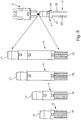
- Fig. 8 is a preferred embodiment of the system according to the invention to see.
- the compact version of the vibronic measuring device consisting of sensor module 1 and 5 electronic module shown.
- the figures to the left of the compact version show different configurations of the contacting module 4.
- a pipe extension 24 and / or a temperature reducing tube 3b or a temperature reducing tube 3a is / is used, a correspondingly dimensioned contacting module 4 is used.
- the vibronic measuring devices can be used at different temperatures, eg at 100 ° C or 150 ° C.
Landscapes
- Physics & Mathematics (AREA)
- Fluid Mechanics (AREA)
- General Physics & Mathematics (AREA)
- Acoustics & Sound (AREA)
- Electromagnetism (AREA)
- Thermal Sciences (AREA)
- Testing Or Calibration Of Command Recording Devices (AREA)
- Measuring Fluid Pressure (AREA)
- Measurement Of Mechanical Vibrations Or Ultrasonic Waves (AREA)
Description
- Die Erfindung betrifft ein modulares System zur Bestimmung und/oder Überwachung einer Prozessgröße eines Mediums oder zur Bestimmung und/oder Überwachung eines vorgegebenen Füllstands eines Mediums in einem Behälter.
- Sensoren zur Bestimmung und Überwachung des Grenzstands von flüssigen Medien und rieselfähigen Feststoffen werden von der Anmelderin unter der Bezeichnung LIQUIPHANT und SOLIPHANT angeboten und vertrieben. Bei den Prozessgrößen, die neben dem Füllstand (Grenzstanddetektion) mit vibronischen Sensoren überwacht werden können, handelt es sich insbesondere um die Prozessgrößen Dichte und die Viskosität. Unter der Bezeichnung LIQUIPHANT Dichte wird von der Anmelderin ein zur Dichtemessung geeigneter Sensor angeboten und vertrieben. Darüber hinaus ist die Anmelderin Inhaberin einer Vielzahl von Schutzrechten, die sich auf vibronische Sensoren zur Grenzstand-, Dichte- und/oder Viskositätsmessung beziehen.
- Für den Antrieb von vibronischen Sensoren wird entweder ein piezoelektrischer Bimorphantrieb oder ein piezoelektrischer Stapelantrieb verwendet. Bei einem Bimorphantrieb ist ein scheibenförmiges piezoelektrisches Element kraftschlüssig mit einer Membran, an der die schwingfähige Einheit befestigt ist, verbunden. Das scheibenförmige Element ist in unterschiedlichen Segmenten unterschiedlich polarisiert. Bei einem Stapelantrieb sind z.B. auf einem Bolzen mehrere kraftschlüssig untereinander und mit der schwingfähigen Einheit verbundene piezoelektrische Elemente angeordnet, wobei einige piezoelektrischen Elemente durch ein elektrisches Wechselsignal zu Schwingungen angeregt werden, während die verbleibenden piezoelektrischen Elemente die Schwingungen der schwingfähigen Einheit erfassen und in ein elektrisches Antwort-Wechselsignal umwandeln.
- Die schwingfähige Einheit eines vibronischen Messgeräts weist bevorzugt zwei in den Behälter ragende Schwingstäbe auf, die an der dem Medium zugewandten Außenfläche einer Membran befestigt sind. Bekannt geworden sind jedoch auch vibronische Messgeräte mit einem Einstab. Die als Erregereinheit dienenden piezoelektrischen Elemente werden mit einem Wechselspannungssignal beaufschlagt, wodurch die beiden Schwingstäbe der schwingfähigen Einheit zu gegensinnigen Schwingungen quer zur Längsachse des vibronischen Messgeräts angeregt werden. Die Empfangseinheit empfängt die Schwingungen der mechanischen schwingfähigen Einheit und wandelt sie in ein elektrisches Wechselspannungssignal um. Zeigt sich eine Änderungen in den Schwinggrößen, tritt z.B. eine Frequenzänderung der Schwingung der schwingfähigen Einheit auf, so ist dies der Auslöser für eine entsprechende Meldung des vibronischen Füllstandsmessgeräts, die im Falle der Verwendung als Überfüllsicherung lautet: "Schwingfähige Einheit ist in Kontakt mit dem Medium" bzw. "Grenzstand erreicht" oder "schwingfähige Einheit schwingt frei" bzw. "Grenzstand ist nicht erreicht". Zur Dichte- und/oder Viskositätsmessung wird gleichfalls das Antwort-Wechselspannungssignal geeignet ausgewertet.
- Vibronische Messgeräte werden von der Anmelderin entweder in einer Kompaktversion oder in Versionen mit einer Rohrverlängerung und/oder einer Temperaturreduziereinheit angeboten und vertrieben. Beispielsweise ist die Kompaktversion so ausgelegt, dass sie bei Temperaturen bis zu z.B. 100°C eingesetzt werden kann. Bei der Kompaktversion ist das Sensormodul - bestehend aus der schwingfähigen Einheit und dem mechanischen bzw. elektromechanischen Teil der Erreger-/Empfangseinheit - über eine mechanische und elektrische/elektronische Schnittstelle unmittelbar mit dem Elektronikmodul - elektrischer/elektronischer Teil der Erreger-/Empfangs-einheit und der Auswerteeinheit - verbunden. Um bei Temperaturen oberhalb von 100°C eine Beeinträchtigung oder Zerstörung der temperatur-empfindlichen Komponenten des Elektronikmoduls zu vermeiden, wird zwischen Sensormodul und das Elektronikmodul eine Temperaturreduzier-einheit angeordnet. Hierbei hängt die Länge der Temperaturreduziereinheit von der am Einsatzort des vibronischen Messgeräts herrschenden Umgebungstemperatur ab. Über eine Rohrverlängerung wird gleichfalls die Distanz zwischen dem Sensormodul und dem Elektronikmodul vergrößert. Darüber hinaus hat die Rohrverlängerung die Aufgabe, die Lage des Schaltpunktes des vibronischen Messgeräts in dem Behälter zu ändern. Damit das vibronische Messgerät unabhängig von seiner Länge in gleicher Anwendung ein vergleichbares Verhalten aufweist, ist es erforderlich, das Elektronikmodul in Abhängigkeit von der Länge des vibronischen Sensors unterschiedlich aufzubauen: Infolge der verlängerten elektrischen Leitungen treten nämlich Koppelkapazitäten auf, die sich den Wechselspannungssignalen überlagern und das Verhalten des vibronischen Messgeräts beeinflussen.
- Der Erfindung liegt die Aufgabe zugrunde, ein universell einsetzbares, kostengünstiges vibronisches Messgerät vorzuschlagen.
- Die Aufgabe wird gelöst durch ein modulares System zur Bestimmung und/oder Überwachung einer Prozessgröße eines Mediums oder zur Bestimmung und/oder Überwachung eines vorgegebenen Füllstands eines Mediums in einem Behälter gemäß dem unabhängigen Patentanspruch 1.
-
WO 03/054492 A1 - Die Länge des Kontaktierungsmoduls ist von dem mechanischen Aufbau des vibronischen Messgeräts abhängig. So ist erfindungsgemäß zwischen dem Sensormodul und einem Prozessanschluss, über den das Messgerät in einer Behälterwandung montiert ist, eine Rohrverlängerung vorgesehen zwischen dem Prozessanschluss und der Elektronikeinheit ist bei Bedarf eine Temperaturreduziereinheit, insbesondere ein Temperaturreduzierrohr vorgesehen. Bei der Kompaktversion erfolgt die Verbindung zwischen Sensormodul und Elektronikmodul unmittelbar bzw. direkt - also ohne das entsprechend dimensionierte Kontaktierungsmodul und ohne die Rohrverlängerung und/oder das Temperaturreduzierrohr. Da in diesem Fall die Koppelkapazitäten auf den elektrischen Pfaden gering sind, wird erfindungsgemäß lediglich einer der beiden in der Elektronikeinheit vorgesehenen Koppelpfade aktiviert.
- Wird hingegen die verlängerte Version des vibronischen Messgeräts mit Rohrverlängerung und/oder Temperaturreduzierrohr und mit entsprechend abgestimmtem Kontaktierungsmodul verwendet, so werden die beiden Koppelpfade in der Elektronikeinheit aktiviert, um die auf den elektrischen Pfaden auftretenden Koppelkapazitäten zu eliminieren.
- Der Vorteil der erfindungsgemäßen Lösung ist darin zu sehen, dass keine zusätzlichen Elektronikvarianten und/oder keine zusätzlichen Sensormodulvarianten benötigt werden. Das Sensormodul und das Elektronikmodul sind stets gleich ausgestaltet, unabhängig davon, ob ein Kontaktierungsmodul verwendet wird und welche Dimensionierung das Kontaktierungsmodul hat. Fertigungstechnisch ist dies natürlich ein herausragender Vorteil gegenüber den bislang bekannten Lösungen, bei denen zumindest das Elektronikmodul in Abhängigkeit von der Distanz zwischen Sensormodul und Elektronikmodul verändert werden musste.
- Weiterhin ist das modulare Konzept erfindungsgemäß so ausgelegt, dass die einzelnen Module in einfacher Weise durch Zusammenstecken miteinander verbunden werden können. Hierdurch wird die Endmontage erheblich vereinfacht. Darüber hinaus sind die beiden Schnittstellen in den Endbereichen des Kontaktierungsmoduls unterschiedlich ausgestaltet, wodurch eine fehlerhafte Montage der einzelnen Module ausgeschlossen wird. Auch sind die Schnittstellen konstruktiv derart ausgestaltet, dass die relativen Höhenpositionen der einzelnen Module bei der Montage genau definiert sind.
- Weiterhin sind die Kontaktbuchsen bevorzugt als Federkontakte ausgestaltet, während die Kontaktstifte selbst starr ausgestaltet sind. Durch die federnde, kraftschlüssige Verbindung von Federkontakten und Kontaktstiften wird erreicht, dass keine zusätzlichen mechanischen Belastungen auf die Verbindungsbereiche übertragen werden. Insbesondere können sich die starren Kontaktstifte frei zwischen den Federkontakten ausrichten. Man redet in diesem Zusammenhang auch von einer schwimmenden Lagerung der Kontaktstifte. Da die Kontaktstifte starr ausgebildet sind, werden unerwünschte parasitäre Effekte vermieden. Störende parasitäre Effekte treten insbesondere bei flexiblen Verbindungsleitungen auf, da parasitäre Effekte generell von der Lage der Verbindungsleitungen abhängig sind.
- Um die Anforderungen an die Temperaturbeständigkeit zu erfüllen, besteht das Kontaktierungsmodul aus einem Kunststoff, der für die am Einsatzort maximal herrschende Temperatur ausgelegt ist. Die Federkontakte und die Kontaktstifte sind aus einem temperaturbeständigen Metall gefertigt. In den Verbindungsbereichen sind sie bevorzugt vergoldet.
- Im Falle einer Demontage ist es wichtig, dass das komplette Kontaktierungsmodul aus dem rohrförmigen Gehäuse des vibronischen Messgeräts herausgezogen werden kann. Daher ist das Kontaktierungsmodul in einer vorteilhaften Weiterbildung so ausgestaltet, dass die dem frei zugänglichen Endbereich des Kontaktierungsmoduls näher liegende Schnittstelle eine größere Steckkraft aufweist als die Schnittstelle, die sich lösen soll und die am entgegengesetzten Endbereich des Kontaktierungsmoduls vorgesehen ist.
- Gemäß einer vorteilhaften Ausgestaltung des erfindungsgemäßen Systems ist das Elektronikmodul so ausgestaltet, dass Koppelkapazitäten, die bei Verwendung eines Kontaktierungsmoduls aufgrund der verlängerten elektrischen Pfade auftreten, zumindest näherungsweise kompensiert werden. Da bei den verlängerten Versionen des vibronischen Messgeräts auftretende Koppelkapazitäten erfindungsgemäß zumindest weitgehend eliminiert werden, ist das Verhalten des vibronischen Messgeräts - unabhängig von dessen Länge - in identischen Anwendungen zumindest näherungsweise gleich.
- Gemäß einer vorteilhaften Weiterbildung des erfindungsgemäßen Systems wird vorgeschlagen, zur Verbindung von Sensormodul und Elektronikmodul oder zur Verbindung von Sensormodul und Kontaktierungsmodul und Kontaktierungsmodul und Elektronikmodul jeweils zumindest vier Kontaktstifte und zumindest vier korrespondierende Kontaktbuchsen vorzusehen. Insbesondere sind sechs oder mehr Kontaktstifte und Kontaktbuchsen vorteilhaft, wobei jeweils mindestens zwei Kontaktstifte und Kontaktbuchsen einen Massepfad bilden, während die verbleibenden Kontaktstifte und Kontaktbuchsen zwei elektrische Pfade bilden.
- Im Falle der Verwendung als Kompaktversion - also im Falle der unmittelbaren Verbindung von Sensormodul und Elektronikmodul - sind die Kontaktstifte und Kontaktbuchsen von Sensormodul und Elektronikmodul so ausgelegt, dass einer der beiden Koppelpfade auf Masse gelegt und daher deaktiviert ist.
- Hingegen sind die Kontaktstifte und Kontaktbuchsen zur Verbindung von Sensormodul und Kontaktierungsmodul bzw. zur Verbindung von Kontaktierungsmodul und Elektronikmodul im Falle der Verwendung der Version mit Rohrverlängerung so ausgelegt, dass die beiden elektrischen Koppelpfade aktiviert sind.
- Gemäß einer vorteilhaften Ausgestaltung des erfindungsgemäßen Systems wird vorgeschlagen, als Erreger-/Empfangseinheit ein scheibenförmiges piezoelektrisches Element mit vier Segmenten gleicher Dimension zu verwenden, wobei zwei Segmente eine Polarisierung, z.B. +, und zwei Segmente eine entgegengesetzte Polarisierung, z.B. -, aufweisen. Es handelt sich somit um einen Bimorphantrieb mit vier Segmenten. Geeignete Bimorphantriebe sind in der
EP 1 281 051 B1 und derEP 1 759 175 A2 ausführlich beschrieben. - Darüber hinaus wird in einer Ausgestaltung des zuvor beschriebenen Bimorphantrieb angeregt, dass jeweils ein Koppelpfad die polarisierten Segmente und ein Koppelpfad die entgegengesetzt polarisierten Segmente miteinander verbindet bzw. koppelt.
- Als besonders vorteilhaft wird es in Zusammenhang mit der erfindungsgemäßen Lösung angesehen, wenn in die elektrischen Koppelpfade Kondensatoren geschaltet sind, die so ausgelegt sind, dass sie die in den verlängerten elektrischen Pfaden auftretenden Koppelkapazitäten zumindest teilweise, bevorzugt jedoch in Gänze kompensieren. Bevorzugt sind die Kondensatoren in dem Elektronikmodul angeordnet.
- Wie bereits zuvor gesagt, ist es besonders vorteilhaft, wenn das Sensormodul und das Elektronikmodul bei der unmittelbaren Verbindung von Sensormodul und Elektronikmodul und bei der Verwendung eines Kontaktierungsmoduls identisch ausgestaltet sind. Liegt eine derartige Ausgestaltung vor, so ist die Variantenvielfalt minimal. Das erfindungsgemäße System bzw. der erfindungsgemäße Bausatz erlaubt daher eine sehr kostengünstige Fertigung von vibronischen Messgeräten in unterschiedlichsten Anwendungen.
- Die Erfindung wird anhand der nachfolgenden Figuren näher erläutert. Es zeigt:
-
Fig. 1 : ein Blockschaltbild, das das erfindungsgemäße System in der Kompaktversion zeigt, -
Fig. 2 : ein Blockschaltbild, das das erfindungsgemäße System als verlängerte Version zeigt, -
Fig. 3 : eine Draufsicht auf ein piezoelektrisches Element, das bei einem Bimorphantrieb eingesetzt wird, -
Fig. 4a : einen Längsschnitt durch eine erste kurze Variante des Kontaktierungsmoduls, -
Fig. 4b : eine perspektivische Ansicht der dem Elektronikmodul zugewandten Schnittstelle des inFig. 4a gezeigten Kontaktierungsmoduls, -
Fig. 4c : eine perspektivische Ansicht der dem Sensormodul zugewandten Schnittstelle des inFig. 4a gezeigten Kontaktierungsmoduls, -
Fig. 5 : einen Längsschnitt durch eine verlängerte Variante des Kontaktierungsmoduls, -
Fig. 6 : eine Explosionsdarstellung des vibronischen Messgeräts in der Kompaktversion, -
Fig. 7 : eine Explosionsdarstellung des vibronischen Messgeräts in einer verlängerten Version und -
Fig. 8 : eine Darstellung einer bevorzugten Ausführungsform des erfindungsgemäßen Systems mit fünf unterschiedlichen Versionen. -
Fig. 1 zeigt ein Blockschaltbild einer vorteilhaften Ausgestaltung, die bei dem erfindungsgemäßen System in der Ausgestaltung als Kompaktversion verwendet wird. Bei der Kompaktversion sind das Sensormodul 1 und das Elektronikmodul 5 unmittelbar miteinander verbunden. Die beiden Koppelpfade 9, 10 sind dem Elektronikmodul 5 zugeordnet. In jedem Koppelpfad 9, 10 sind zwei Kondensatoren 11a, 11b, 12a, 12b in Reihe geschaltet. Bei der Kompaktversion ist nur einer der beiden Koppelpfade 9, 10 - hier der Koppelpfad 10 - aktiviert. Der Koppelpfad 9 liegt auf Masse GND und ist somit deaktiviert. - In
Fig. 2 ist ein Blockschaltbild einer vorteilhaften Ausgestaltung dargestellt, die das erfindungsgemäße System in einer der verlängerten Versionen zeigt, wenn zwischen dem Sensormodul 1 und dem Elektronikmodul 5 ein Kontaktierungsmodul 4 verwendet wird. Bei den verlängerten Versionen sind beide Koppelpfade 9, 10 aktiviert. - Bei der verlängerten Version sind das Sensormodul 1 und das Elektronikmodul 5 mittelbar über zwei infolge des Kontaktierungsmoduls 4 verlängerte elektrische Pfade 8a, 8b miteinander verbunden. Der mittlere Pfad ist der Massepfad 13.
- Anhand der Figuren
Fig. 4, Fig. 5 undFig. 8 ist ersichtlich, dass die dem Sensormodul 1 zugewandte Schnittstelle 18 des Kontaktierungsmoduls 4 analog ausgestaltet ist wie die Schnittstelle des Elektronikmoduls 5, und die dem Elektronikmodul 5 zugewandte Schnittstelle 17 ist identisch ausgestaltet wie die Schnittstelle des Sensormoduls 1. Durch einfaches Zusammenstecken der Module 1, 5 bzw. 1, 4, 5 lässt sich je nach Bedarf die Kompaktversion oder die verlängerte Version des vibronischen Messgeräts aus den Einzelkomponenten bilden. - Ab einer definierten Länge der verlängerten Versionen des vibronischen Messgeräts sind beide Koppelpfade 9, 10 aktiviert, um auf den verlängerten Pfaden 8a, 8b auftretende Koppelkapazitäten zu beseitigen. Während bei der Kompaktversion und ggf. bei Verwendung einer kurzen Version des Kontaktierungsmoduls 4 drei elektrische Pfade 8a, 8b, 13 mit sechs Kontaktierungen 14, 15 vorgesehen sind, weist die verlängerte Version nur zwei elektrische verlängerte Pfade 8a, 8b auf. Die in den Koppelpfaden 9, 10 befindlichen Kondensatoren 11a, 11b, 12a, 12b sind so gewählt, dass Koppelkapazitäten, die aufgrund der verlängerten elektrischen Pfade 8a, 8b auftreten, zumindest näherungsweise kompensiert werden.
- Das Sensormodul 1 und das Elektronikmodul 5 sind bei allen Versionen des vibronischen Messgeräts (sh. insbesondere
Fig. 8 ) gleich ausgestaltet. Damit dies möglich ist, wird in Abhängigkeit von der Verwendung und den Bedingungen am Einsatzort des Messgeräts ein Kontaktierungsmodul 4 der geeigneten Länge gewählt. Die Länge des Kontaktierungsmoduls 4 ist abhängig davon, ob eine Rohrverlängerung 24 und/oder ein Temperaturreduzierrohr 3b verwendet werden/wird. Da durch Verwendung der Rohrverlängerung 24 und/oder der Temperaturreduziereinheit 3b der Abstand des Elektronikmoduls 5 zum Prozess verändert wird, kann das vibronische Messgerät auch in Hochtemperatur-Anwendungen zum Einsatz kommen. Über die Rohrverlängerung 24 lässt sich darüber hinaus der Schaltpunkt des vibronischen Messgeräts verschieben. - Das Sensormodul 1 selbst besteht aus einem rohrförmigen Halsbereich 20, der in einem Endbereich von einer Membran 21 verschlossen ist. An der Membran 21 ist die schwingfähige Einheit 2 befestigt, die im gezeigten Fall aus zwei Schwingstäben 22 besteht. Es versteht sich von selbst, dass anstelle der Schwinggabel auch ein Einstab eingesetzt werden kann.
- Während des Betriebs ist das Messgerät über den Prozessanschluss 19 derart an dem Behälter angeordnet, dass die schwingfähige Einheit 2 bis zu einer definierten Eintauchtiefe in das Medium eintaucht und Messwerte hinsichtlich der Dichte oder der Viskosität des Mediums ermittelt, oder dass die schwingfähige Einheit 2 auf der Höhe des vorgegebenen Füllstandes angebracht ist und zumindest temporär mit dem Medium in Kontakt kommt. Wie bereits erwähnt, kann über die Rohrverlängerung 24 der Schaltpunkt des vibronischen Messgeräts variiert werden.
- Die schwingfähige Einheit 2 wird über eine Erreger-/Empfangseinheit 6a, 6b und ein Wechselspannungssignal, das von der Regel-/Auswerteeinheit 7 zur Verfügung gestellt wird, zu Schwingungen anregt. Die Antwort-Schwingung wird von zumindest einem piezoelektrischen Element 6b zur Verfügung gestellt, und das entsprechende Antwortsignal wird von der Regel-/Auswerteeinheit 7 ausgewertet. Anhand von zumindest einer Schwinggröße der Schwingung oder anhand einer Änderung einer Schwinggröße der Schwingung wird Information über die Prozessgröße oder das Erreichen des vorbestimmten Füllstandes zur Verfügung stellt
- In
Fig. 3 ist eine bevorzugte Ausgestaltung einer Erreger-/Empfangseinheit dargestellt. Bei der Erreger-/Empfangseinheit handelt es sich um ein scheibenförmiges piezoelektrisches Element 6b, das vier Segmente 16 aufweist. Zwei Segmente 16 haben eine Polarisierung (+), und zwei Segmente 16 haben eine entgegengesetzte Polarisierung (-). Das Sendesignal S-, S+ wird - wie inFig. 3 dargestellt - an zwei Segmente 16 des piezoelektrischen Elements 6b angelegt. Das Empfangssignal E-, E+ wird an den beiden verbleibenden Segmenten abgegriffen. Ein entsprechender Antrieb wird von der Anmelderin bereits in Produkten genutzt und ist unter der Bezeichnung Bimorphantrieb bekannt geworden. Bekannte Ausgestaltungen von Bimorphantrieben sind in derEP 1 281 051 B1 und derEP 1 759 175 A2 beschrieben. Selbstverständlich ist die erfindungsgemäße Lösung nicht auf die inFig. 3 gezeigte Segmentierung des piezoelektrischen Elements 6b beschränkt. - Zur Verbindung des Kontaktierungsmoduls 4 mit dem Sensormodul 1 und dem Elektronikmodul 5 sind bei der gezeigten Ausgestaltung der erfindungsgemäßen Vorrichtung jeweils sechs Kontaktstifte 14 und jeweils sechs korrespondierende Kontaktbuchsen 15 vorgesehen. Gut zu sehen ist diese Ausgestaltung auch in den Figuren
Fig. 4a, Fig. 4b und Fig. 5 . Bei der inFig. 1 dargestellten Kompaktversion wird das Sensormodul 1 direkt auf das Elektronikmodul 5 gesteckt. Der Mittelpunkt des Kopplungspfades 9 wird über die mittig angeordneten elektrischen Kontakte 14, 15 und über den Kurzschluss auf dem Sensormodul 1 auf Masse gelegt. Somit ist bei der Kompaktversion einer der beiden Koppelpfade - hier der Koppelpfad 9 - nicht aktiv. - Im Falle der unmittelbaren Verbindung von Sensormodul 1 und Elektronikmodul 5 sind die Kontaktstifte 14 und Kontaktbuchsen 15 von Sensormodul 1 und Elektronikmodul 5 folglich so ausgelegt, dass einer der beiden Koppelpfade 9, 10 auf Masse gelegt und deaktiviert ist.
- Im Falle der Verwendung eines entsprechend langen Kontaktierungsmoduls 4 sind die Kontaktstifte 14 und die Kontaktbuchsen 15 zur Verbindung von Sensormodul 1 und Kontaktierungsmodul 4 bzw. zur Verbindung von Kontaktierungsmodul 4 und Elektronikmodul 5 so ausgelegt, dass beide elektrische Koppelpfade 9, 10 aktiviert sind. Hierbei koppelt ein Koppelpfad 9 die polarisierten Segmente 16+ und ein Koppelpfad 10 die entgegengesetzt polarisierten Segmente 16- miteinander. In die elektrischen Koppelpfade 9, 10 sind Kondensatoren 11a, 11b, 12a, 12b geschaltet, die so ausgelegt sind, dass sie die in den verlängerten elektrischen Pfaden 8a, 8b auftretenden Koppelkapazitäten zumindest teilweise kompensieren. Insbesondere werden die Koppelkapazitäten durch die Schaltung zumindest insoweit eliminiert, dass das vibronische Messgerät ein nahezu identisches Verhalten in näherungsweise gleichen Anwendungen bei allen Versionen des vibronischen Messgerätes zeigt.
- Bevorzugt sind die Kondensatoren 11a, 11b, 12a, 12b in dem Elektronikmodul 5 angeordnet. Da das Elektronikmodul 5 und das Sensormodul 1 bei allen Versionen identisch sein sollen, müssen die Kondensatoren 11a, 11b, 12a, 12b so bemessen sein, dass die resultierenden Abweichungen im Verhalten in einem vorgegebenen Toleranzbereich liegen. Selbstverständlich können die Kondensatoren 11a, 11b, 12a, 12b auch auf jede Variante des Kontaktierungsmoduls 4 individuell abgestimmt werden. Erfindungsgemäß ist ab einer bestimmten Länge des Kontaktierungsmoduls 4 der Mittelpunkt eines der beiden Koppelpfade 9, 10 nicht mehr mit Masse verbunden. Entweder sind die beiden mittleren elektrischen Pfade 8c gekürzt, oder sie fehlen. Folglich sind die beiden Koppelpfade 9, 10 aktiviert. Durch diese entgegengesetzte Kopplung können die unerwünschten Koppelkapazitäten, die infolge des Kontaktierungsmoduls 4 auf den verlängerten elektrischen Pfaden 8a, 8b auftreten, kompensiert werden.
- In den Figuren
Fig. 4a, Fig. 4b und Fig. 4c sind unterschiedliche Ansichten eines kurzen Kontaktierungsmoduls 4 gezeigt, das bei allen Versionen eingesetzt wird. Neben den elektrischen Pfaden 8a, 8b sind auch die Schnittstellen 17, 18 im Detail gezeigt.Fig. 5 zeigt einen Längsschnitt durch ein Kontaktierungsmodul 4, das bei einer der verlängerten Versionen des Messgeräts eingesetzt wird. -
Fig. 6 zeigt eine Explosionsdarstellung einer Ausgestaltung eines vibronischen Messgeräts ohne Kontaktierungsmodul. InFig. 7 ist eine Explosionsdarstellung einer Ausgestaltung eines vibronischen Messgeräts, bei dem ein Kontaktierungsmodul 4 eingesetzt ist. - Das modulare erfindungsgemäße System, das in
Fig. 8 noch einmal verdeutlicht ist, hat eine Vielzahl von Vorteilen: - Die steckbaren Module 1, 4, 5 ermöglichen ein einfaches Verbauen in der Endmontage
- Eine wertschöpfende auf die jeweiligen Erfordernisse angepasste Produktion kann auch in entfernten Fertigungsstätten erfolgen
- Durch die unterschiedliche Geometrische Ausgestaltung der einzelnen Schnittstellen 17, 18 ist ein fehlerhaftes Zusammenstecken der Module 1, 4, 5 ausgeschlossen
- Bei der in
Fig. 4a gezeigten Ausgestaltung sind die elektrischen Kontakte zwischen den Kontaktstiften 14 und den Kontaktbuchsen 15 als Federkontakte ausgestaltet. Insbesondere werden anstelle von Kontaktbuchsen Führungen 15 bzw. Steckhülsen verwendet. Die Führungen bzw. Steckhülsen 15 sind so ausgestaltet, dass sie eine grobe Positionierung der leitenden elektrischen Verbindungen bzw. elektrischen Pfade 8a, 8b gewährleisten, allerdings bleiben die einzelnen elektrischen Federkontakte 14, 15 ohne zusätzliche mechanische Belastungen. Die Kontaktstifte 14 können sich frei zwischen den Federkontakten 15 ausrichten. Man redet in diesem Zusammenhang auch von einer schwimmenden Lagerung der Kontaktelemente 14, 15. - Die Federkontakte 15 geben eine definierte Lage vor. Infolge der starren Verbindungsleitungen 8a, 8b treten keine parasitären Effekte auf - wie sie z.B. bei flexiblen Verbindungsleitungen je nach Lage entstehen können.
- Durch geeignete Kombination eines Kunststoffes, z.B. PEI, und Metall lässt sich das Kontaktierungsmodul 4 temperaturresistent gestalten.
- Das Kontaktierungsmodul 4 ist weiterhin so ausgelegt, dass es bei einer Demontage als Einzelteil aus dem rohrförmigen Gehäuse des vibronischen Messgeräts herausgezogen werden kann. Hierzu ist insbesondere die Steckkraft im oberen Endbereich des Kontaktierungsmoduls 4 größer als die Steckkraft am entgegengesetzten Endbereich des Kontaktierungsmoduls 4.
- In
Fig. 8 ist eine bevorzugte Ausgestaltung des erfindungsgemäßen Systems zu sehen. Im rechten Bereich vonFig. 8 ist die Kompaktversion des vibronischen Messgeräts, bestehend aus Sensormodul 1 und Elektronikmodul 5, gezeigt. Die Figuren links von der Kompaktversion zeigen unterschiedliche Ausgestaltungen des Kontaktierungsmoduls 4. Je nachdem ob eine Rohrverlängerung 24 und/oder ein Temperaturreduzierrohr 3b bzw. ein Temperaturreduzierrohr 3a verwendet werden/wird, wird ein entsprechend dimensioniertes Kontaktierungsmodul 4 verwendet. Je nach Ausgestaltung sind die vibronischen Messgeräte bei unterschiedlichen Temperaturen, z.B. bei 100°C oder 150°C einsetzbar. - Die Länge des vibronischen Messgeräts wird durch zwei unabhängige Faktoren bestimmt: 1) die Prozesstemperatur, wobei das kurze Gehäuse für Temperaturen bis 100 °C und das lange Gehäuse für Temperaturen bis 150 °C ausgelegt ist, und 2) die Lage des Schaltpunkts mit oder ohne Rohrverlängerung 24. Entsprechend ergeben sich vier unterschiedliche Längen und entsprechend vier unterschiedlich dimensionierte Kontaktierungsmodule 4.
- Kurzes Gehäuse bis 100 °C ohne Rohrverlängerung 24;
- Langes Gehäuse (also mit Temperaturreduzierrohr 3b) bis 150 °C ohne Rohrverlängerung 24;
- Kurzes Gehäuse bis 100 °C mit Rohrverlängerung 24;
- Langes Gehäuse bis 150 °C mit Rohrverlängerung 24.
-
- 1
- Sensormodul
- 2
- schwingfähige Einheit
- 3a
- Temperaturreduziereinheit/Temperaturreduzierrohr - kurzes Gehäuse
- 3b
- Temperaturreduziereinheit/Temperaturreduzierrohr - langes Gehäuse
- 4
- Kontaktierungsmodul
- 5
- Elektronikmodul
- 6a
- Erreger-/Empfangseinheit (elektrisch)
- 6b
- Erreger-/Empfangseinheit (piezoelektrisches Element)
- 7
- Auswerteeinheit
- 8a
- elektrischer Pfad
- 8b
- elektrischer Pfad
- 9
- Koppelpfad
- 10
- Koppelpfad
- 11a
- Kondensator
- 11b
- Kondensator
- 12a
- Kondensator
- 12b
- Kondensator
- 13
- Massepfad
- 14
- Kontaktstift
- 15
- Kontaktbuchse / Führung / Steckhülse
- 16
- Segment
- 17
- dem Elektronikmodul zugewandte Schnittstelle
- 18
- dem Sensormodul zugewandte Schnittstelle
- 19
- Prozessanschluss
- 20
- rohrförmiger Halsbereich
- 21
- Membran
- 22
- Schwingstab
- 23
- Distanzhalter
- 24
- Rohrverlängerung
Claims (15)
- Modulares System für ein vibronisches Messgerät zur Bestimmung und/oder Überwachung einer Prozessgröße eines Mediums oder zur Bestimmung und/oder Überwachung eines vorgegebenen Füllstands eines Mediums in einem Behälter, mit einem Sensormodul (1) mit einer schwingfähigen Einheit (2), das derart in dem Behälter angeordnet ist, dass die schwingfähige Einheit (2) bis zu einer definierten Eintauchtiefe in das Medium eintaucht, oder dass die schwingfähige Einheit (2) auf der Höhe des vorgegebenen Füllstandes angebracht ist,
und mit einem Elektronikmodul (5), bestehend aus einer Erreger-/Empfangseinheit (6),
die die schwingfähige Einheit (2) zu Schwingungen anregt und die Schwingungen der schwingfähigen Einheit empfängt, wobei dem Elektronikmodul zwei elektrische Koppelpfade zugeordnet sind, und mit einer Regel-/Auswerteeinheit (7), die anhand von zumindest einer Schwinggröße der Schwingung oder anhand einer Änderungen einer Schwinggröße der Schwingung Information über die Prozessgröße oder das Erreichen des vorbestimmten Füllstandes zur Verfügung stellt,
wobei die einzelnen Module (1, 5; 1, 4, 5) durch Zusammenstecken miteinander verbunden werden können,
dadurch gekennzeichnet dass
das Sensormodul (1) und das Elektronikmodul (5) entweder elektrisch unmittelbar miteinander verbunden sind und einer der beiden elektrischen Koppelpfade (9; 10) aktiviert ist und der andere der beiden elektrischen Koppelpfade (9;10) deaktiviert ist oder wobei das Sensormodul (1) und das Elektronikmodul (5) über ein Kontaktierungsmodul (4) und infolge des Kontaktierungsmoduls (4) über verlängerte elektrische Pfade (8a, 8b) miteinander verbunden sind und wobei die beiden elektrischen Koppelpfade (9, 10) aktiviert sind,
wobei das Kontaktierungsmodul (4) in Abhängigkeit von der am Einsatzort des vibronischen Messgeräts herrschenden Temperatur und/oder in Abhängigkeit von dem Schaltpunkt des vibronischen Messgeräts in Verbindung mit einer Rohrverlängerung (24) und/oder einem Temperaturreduzierrohr (3b) einer definierten Länge eingesetzt wird, und wobei das Sensormodul (1) und das Elektronikmodul (5) im Falle der unmittelbaren elektrischen Verbindung von Sensormodul (1) und Elektronikmodul (5) und im Falle der Verbindung von Sensormodul (1) und Elektronikmodul (5) über das Kontaktierungsmodul (4) identisch ausgestaltet sind, wobei im Falle der Verbindung von Sensormodul (1) und Elektronikmodul (5) über das Kontaktierungsmodul (4) die dem Sensormodul (1) zugewandte Schnittstelle des Kontaktierungsmoduls (4) analog ausgestaltet ist wie die Schnittstelle des Elektronikmoduls (5), und die dem Elektronikmodul (5) zugewandte Schnittstelle des Kontaktierungsmoduls (4) identisch ausgestaltet ist wie die Schnittstelle des Sensormoduls (1). - Modulares System nach Anspruch 1,
wobei die elektrischen Koppelpfade (9, 10) so ausgestaltet sind, dass Koppelkapazitäten auf den verlängerten elektrischen Pfaden (8a, 8b) zumindest näherungsweise kompensiert werden,
mittels in dem Elektronikmodul (5) angeordneter Kondensatoren (11a, 11b, 12a, 12b), die in die elektrischen Koppelpfade (9, 10) geschaltet und so ausgelegt sind, dass sie die in den verlängerten elektrischen Pfaden (8a, 8b) auftretenden Koppelkapazitäten zumindest teilweise kompensieren. - Modulares System nach Anspruch 1 oder 2,
wobei zur Verbindung von Sensormodul (1) und Elektronikmodul (5) oder zur Verbindung von Sensormodul (1) und Kontaktierungsmodul (4) und Kontaktierungsmodul (4) und Elektronikmodul (5) jeweils zumindest vier Kontaktstifte (14) und zumindest vier korrespondierende Kontaktbuchsen (15) vorgesehen sind. - Modulares System nach einem der Ansprüche 1-3,
wobei sechs oder mehr Kontaktstifte (14) und Kontaktbuchsen (15) vorgesehen sind, wobei jeweils mindestens zwei Kontaktstifte (14) und Kontaktbuchsen (15) einen Massepfad (13) bilden. - Modulares System nach zumindest einem der Ansprüche 1-4,
wobei im Falle der Verbindung von Sensormodul (1) und Elektronikmodul (5) die Kontaktstifte (14) und Kontaktbuchsen (15) von Sensormodul (1) und Elektronikmodul (5) so ausgelegt sind, dass einer der beiden elektrischen Koppelpfade (9, 10) auf Masse gelegt und dadurch deaktiviert ist. - Modulares System nach zumindest einem der Ansprüche 1-4,
wobei im Falle der Verwendung einer Rohrverlängerung (3) und/oder eines Temperaturreduzierrohrs (3b) mit entsprechend dimensioniertem Kontaktierungsmoduls (4) die Kontaktstifte (14) und Kontaktbuchsen (15) zur Verbindung von Sensormodul (1) und Kontaktierungsmodul (4) bzw. zur Verbindung von Kontaktierungsmodul (4) und Elektronikmodul (5) so ausgelegt sind, dass die beiden elektrischen Koppelpfade (9, 10) aktiviert sind. - Modulares System nach zumindest einem der vorhergehenden Ansprüche,
wobei das Sensormodul (1), das Kontaktierungsmodul (4) und das Elektronikmodul (5) so ausgelegt sind, dass die einzelnen Module (1, 4, 5) über Steckverbindungen miteinander verbindbar sind. - Modulares System nach Anspruch 7,
wobei die Schnittstellen (17,18) in den Endbereichen des Kontaktierungsmoduls (4) unterschiedlich ausgestaltet sind. - Modulares System nach einem oder mehreren der vorhergehenden Ansprüche, wobei die Kontaktbuchsen (15) als Federkontakte ausgestaltet und wobei die Kontaktstifte (14) starr ausgebildet sind.
- Modulares System nach zumindest einem der Ansprüche 1-9,
wobei das Kontaktierungsmodul (4) aus einem Kunststoff gefertigt ist, der zumindest bis zu der am Einsatzort maximal herrschenden Temperatur temperaturbeständig ist, und wobei die Kontaktbuchsen (15) bzw. die Federkontakte und die Kontaktstifte (14) aus einem temperaturbeständigen leitfähigen Metall gefertigt sind. - Modulares System nach einem oder mehreren der vorhergehenden Ansprüche, wobei die Schnittstellen (17,18) so ausgestaltet sind, dass die dem frei zugänglichen Endbereich des Kontaktierungsmoduls (4) zugewandte Schnittstelle (17) eine größere Steckkraft aufweist als die Schnittstelle (18), die am entgegengesetzten Endbereich des Kontaktierungsmoduls (4) vorgesehen ist.
- Modulares System nach einem oder mehreren der vorhergehenden Ansprüche, dass die Erreger-/Empfangseinheit (6) aus einem scheibenförmigen piezoelektrischen Element (6b) mit vier Segmenten (16) besteht, wobei zwei Segmente (16) eine Polarisierung (+) und zwei Segmente (16) eine entgegengesetzte Polarisierung (-) aufweisen.
- Modulares System nach Anspruch 12,
wobei einer der beiden elektrischen Koppelpfade (9) die polarisierten Segmente (16+) und der andere der beiden elektrischen Koppelpfade (10) die entgegengesetzt polarisierten Segmente (16-) miteinander koppelt. - Modulares System nach einem oder mehreren der vorhergehenden Ansprüche, wobei das Temperaturreduzierrohr (3b) zwischen einem Prozessanschluss (19) und dem Elektronikmodul (5) vorgesehen ist.
- Modulares System nach einem oder mehreren der vorhergehenden Ansprüche, wobei die Rohrverlängerung (24) zwischen dem Sensormodul (1) und dem Prozessanschluss (19) vorgesehen ist.
Applications Claiming Priority (2)
| Application Number | Priority Date | Filing Date | Title |
|---|---|---|---|
| DE102013114045.9A DE102013114045A1 (de) | 2013-12-13 | 2013-12-13 | System zur Bestimmung und/oder Überwachung einer Prozessgröße eines Mediums |
| PCT/EP2014/074611 WO2015086256A1 (de) | 2013-12-13 | 2014-11-14 | SYSTEM ZUR BESTIMMUNG UND/ODER ÜBERWACHUNG EINER PROZESSGRÖßE EINES MEDIUMS |
Publications (2)
| Publication Number | Publication Date |
|---|---|
| EP3080564A1 EP3080564A1 (de) | 2016-10-19 |
| EP3080564B1 true EP3080564B1 (de) | 2018-08-01 |
Family
ID=51900868
Family Applications (1)
| Application Number | Title | Priority Date | Filing Date |
|---|---|---|---|
| EP14799146.7A Active EP3080564B1 (de) | 2013-12-13 | 2014-11-14 | Modulares system zur bestimmung und/oder überwachung einer prozessgrösse eines mediums oder zur bestimmung und/oder überwachung eines vorgegebenen füllstands eines mediums in einem behälter |
Country Status (5)
| Country | Link |
|---|---|
| US (1) | US10302479B2 (de) |
| EP (1) | EP3080564B1 (de) |
| CN (1) | CN105849512B (de) |
| DE (1) | DE102013114045A1 (de) |
| WO (1) | WO2015086256A1 (de) |
Cited By (1)
| Publication number | Priority date | Publication date | Assignee | Title |
|---|---|---|---|---|
| DE202018106976U1 (de) | 2018-12-06 | 2018-12-18 | Endress + Hauser Wetzer Gmbh + Co. Kg | Feldgerät mit Temperatur-Distanz-Bestimmungseinheit |
Families Citing this family (4)
| Publication number | Priority date | Publication date | Assignee | Title |
|---|---|---|---|---|
| DE102015100661A1 (de) * | 2015-01-19 | 2016-07-21 | Endress + Hauser Flowtec Ag | Vorrichtung zur Bestimmung und/oder Überwachung mindestens einer physikalischen oder chemischen Prozessgröße eines Mediums |
| DE102016122410B4 (de) * | 2016-11-21 | 2019-03-21 | Vega Grieshaber Kg | Vibrationssensor und Verfahren zu dessen Betrieb und Installation |
| DE102020116278A1 (de) * | 2020-06-19 | 2021-12-23 | Endress+Hauser SE+Co. KG | Vibronischer Multisensor |
| DE102022126137A1 (de) * | 2022-10-10 | 2024-04-11 | Vega Grieshaber Kg | Verdrehbares und/oder knickbares Feldgerät |
Family Cites Families (20)
| Publication number | Priority date | Publication date | Assignee | Title |
|---|---|---|---|---|
| DE1773815C3 (de) * | 1968-07-10 | 1984-05-30 | Endress U. Hauser Gmbh U. Co, 7867 Maulburg | Vorrichtung zur Feststellung des Erreichens eines vorbestimmten Füllstands in einem Behälter |
| US3745384A (en) * | 1972-01-07 | 1973-07-10 | Bendix Corp | Resonant pressure sensor |
| DE2631061A1 (de) | 1975-07-11 | 1977-01-27 | Mallory & Co Inc P R | Anordnung zur feststellung eines fluessigkeitspegels |
| DE3215040C2 (de) * | 1982-04-22 | 1985-11-07 | VEGA Grieshaber -GmbH & Co, 7622 Schiltach | Resonanzstab |
| US4740726A (en) * | 1986-07-21 | 1988-04-26 | Nohken Inc. | Vibrator-type level sensor |
| DE29522002U1 (de) | 1995-09-28 | 1999-03-25 | Endress + Hauser GmbH + Co., 79689 Maulburg | Elektronikgehäuse |
| US6236322B1 (en) * | 1998-09-09 | 2001-05-22 | Endress + Hauser Gmbh + Co. | Apparatus for establishing and/or monitoring a predetermined filling level in a container |
| EP1134038A1 (de) | 2000-03-08 | 2001-09-19 | Endress + Hauser GmbH + Co. | Vorrichtung zur Feststellung und/oder Überwachung eines vorbestimmten Füllstandes in einem Behälter |
| DE10022891A1 (de) | 2000-05-10 | 2001-11-15 | Endress Hauser Gmbh Co | Vorrichtung zur Feststellung und/oder Überwachung des Füllstandes eines Füllguts in einem Behälter |
| DE10023306C2 (de) * | 2000-05-15 | 2002-07-11 | Grieshaber Vega Kg | Verfahren zur Ansteuerung von piezoelektrischen Antrieben in Füllstandmessgeräten |
| US6696962B2 (en) | 2001-05-14 | 2004-02-24 | John M. Kelly | Resonant tube level sensor |
| DE10163165A1 (de) | 2001-12-20 | 2003-07-03 | Endress & Hauser Gmbh & Co Kg | Feldgerät und Verfahren zum Betrieb des Feldgerätes |
| DE10260088A1 (de) | 2002-12-19 | 2004-08-05 | Endress + Hauser Gmbh + Co. Kg | Vorrichtung zur Bestimmung und/oder Überwachung mindestens einer physikalischen Größe mit einem Piezoantrieb zur Schwingungserregung und -detektion |
| DE10308087A1 (de) | 2003-02-24 | 2004-09-09 | Endress + Hauser Gmbh + Co. Kg | Schutz vor den Effekten von Kondensatbrücken |
| DE20313695U1 (de) | 2003-09-01 | 2003-12-04 | Endress + Hauser Gmbh + Co. Kg | Feldgerät zur Bestimmung und/oder Überwachung einer Prozessgröße |
| DE102004010992B3 (de) | 2004-03-03 | 2005-10-13 | Endress + Hauser Gmbh + Co. Kg | Vorrichtung zur Bestimmung und/oder Überwachung einer Prozessgrösse |
| DE102005036872B4 (de) | 2005-08-02 | 2016-03-24 | Vega Grieshaber Kg | Vorrichtung zur Vibrations-Füllstand-Grenzstanderfassung und Verfahren zur Vibrations-Füllstand-Grenzstanderfassung |
| DE102007038022B4 (de) | 2007-08-10 | 2021-02-04 | Endress+Hauser SE+Co. KG | Vorrichtung zur Bestimmung und/oder Überwachung einer Prozessgröße |
| EP2650668A1 (de) | 2012-04-12 | 2013-10-16 | Openfield | Dichte- und Viskositätssensor sowie Messverfahren |
| DE202013103798U1 (de) * | 2013-08-22 | 2013-09-04 | Endress + Hauser Gmbh + Co. Kg | Vorrichtung zur Bestimmung und/oder Überwachung mindestens einer Prozessgrösse eines Mediums |
-
2013
- 2013-12-13 DE DE102013114045.9A patent/DE102013114045A1/de not_active Withdrawn
-
2014
- 2014-11-14 EP EP14799146.7A patent/EP3080564B1/de active Active
- 2014-11-14 US US15/103,004 patent/US10302479B2/en active Active
- 2014-11-14 CN CN201480068033.8A patent/CN105849512B/zh active Active
- 2014-11-14 WO PCT/EP2014/074611 patent/WO2015086256A1/de not_active Ceased
Cited By (1)
| Publication number | Priority date | Publication date | Assignee | Title |
|---|---|---|---|---|
| DE202018106976U1 (de) | 2018-12-06 | 2018-12-18 | Endress + Hauser Wetzer Gmbh + Co. Kg | Feldgerät mit Temperatur-Distanz-Bestimmungseinheit |
Also Published As
| Publication number | Publication date |
|---|---|
| US20160305813A1 (en) | 2016-10-20 |
| EP3080564A1 (de) | 2016-10-19 |
| DE102013114045A1 (de) | 2015-06-18 |
| US10302479B2 (en) | 2019-05-28 |
| WO2015086256A1 (de) | 2015-06-18 |
| CN105849512B (zh) | 2019-10-22 |
| CN105849512A (zh) | 2016-08-10 |
Similar Documents
| Publication | Publication Date | Title |
|---|---|---|
| EP1261437B1 (de) | Vorrichtung zur feststellung und/oder überwachung eines vorbestimmten füllstandes in einem behälter | |
| EP0985916B1 (de) | Vorrichtung zur Feststellung und/oder Überwachung eines vorbestimmten Füllstandes in einem Behälter | |
| WO2011032793A1 (de) | Füllstandsmessgerät | |
| EP2464951B1 (de) | Multivariabler sensor zur bestimmung und/oder überwachung des füllstands und der dichte und/oder der viskosität einer flüssigkeit im behälter | |
| WO2015086256A1 (de) | SYSTEM ZUR BESTIMMUNG UND/ODER ÜBERWACHUNG EINER PROZESSGRÖßE EINES MEDIUMS | |
| DE102007038022B4 (de) | Vorrichtung zur Bestimmung und/oder Überwachung einer Prozessgröße | |
| DE102004010992B3 (de) | Vorrichtung zur Bestimmung und/oder Überwachung einer Prozessgrösse | |
| EP0875742B1 (de) | Vorrichtung zur Feststellung und/oder Überwachung eines vorbestimmten Füllstands in einem Behälter | |
| EP0875739B1 (de) | Vorrichtung zur Feststellung und/oder Überwachung eines vorbestimmten Füllstands in einem Behälter | |
| EP1563260B1 (de) | Gehäuse mit reduzierter wärmeleitung für ein messgerät | |
| DE102006048203A1 (de) | Winkelgeschwindigkeitssensor | |
| DE102007057124A1 (de) | Vorrichtung zur Bestimmung und/oder Überwachung einer Prozessgröße eines Mediums | |
| WO2025011941A1 (de) | Vibrationssensor | |
| DE102013102712A1 (de) | Vorrichtung zur Bestimmung und/oder Überwachung einer Prozessgröße eines Mediums | |
| EP4246100B1 (de) | Vibronischer grenzstandsensor mit beschleunigungssensor | |
| WO2025021407A1 (de) | Vibrationssensor | |
| DE102016125822A1 (de) | Vibrationssensor | |
| EP0875740B1 (de) | Vorrichtung zur Feststellung und/oder Überwachung eines vorbestimmten Füllstands in einem Behälter | |
| EP1966569A2 (de) | Füllstandmessanordnung mit einer sicherheitsabschaltung bei hohen temperaturen | |
| EP2044817B1 (de) | Platine mit schwingungsauslösendem elektronischen bauteil | |
| EP3700683B1 (de) | Ultraschallwandler mit zumindest einem piezo-elektrischen oszillator | |
| DE102006013255A1 (de) | Vorrichtung zur Bestimmung und/oder Überwachung einer Prozessgröße | |
| DE202013103798U1 (de) | Vorrichtung zur Bestimmung und/oder Überwachung mindestens einer Prozessgrösse eines Mediums | |
| WO2008043119A2 (de) | Saw-identifikationseinheit, sensor mit saw-element, anschlusskabel, sowie messanordnung | |
| DE102006031905A1 (de) | Vorrichtung zur Bestimmung und/oder Überwachung einer Prozessgröße |
Legal Events
| Date | Code | Title | Description |
|---|---|---|---|
| PUAI | Public reference made under article 153(3) epc to a published international application that has entered the european phase |
Free format text: ORIGINAL CODE: 0009012 |
|
| 17P | Request for examination filed |
Effective date: 20160523 |
|
| AK | Designated contracting states |
Kind code of ref document: A1 Designated state(s): AL AT BE BG CH CY CZ DE DK EE ES FI FR GB GR HR HU IE IS IT LI LT LU LV MC MK MT NL NO PL PT RO RS SE SI SK SM TR |
|
| AX | Request for extension of the european patent |
Extension state: BA ME |
|
| RIN1 | Information on inventor provided before grant (corrected) |
Inventor name: KRUMBHOLZ, ANDREAS Inventor name: FERRARO, FRANCO Inventor name: DOETSCH, MICHAEL Inventor name: WALSER, PHILIPP Inventor name: SCHMIDT, ROBERT |
|
| DAX | Request for extension of the european patent (deleted) | ||
| 17Q | First examination report despatched |
Effective date: 20170731 |
|
| GRAP | Despatch of communication of intention to grant a patent |
Free format text: ORIGINAL CODE: EPIDOSNIGR1 |
|
| INTG | Intention to grant announced |
Effective date: 20180316 |
|
| RAP1 | Party data changed (applicant data changed or rights of an application transferred) |
Owner name: ENDRESS+HAUSER SE+CO. KG |
|
| GRAS | Grant fee paid |
Free format text: ORIGINAL CODE: EPIDOSNIGR3 |
|
| GRAA | (expected) grant |
Free format text: ORIGINAL CODE: 0009210 |
|
| AK | Designated contracting states |
Kind code of ref document: B1 Designated state(s): AL AT BE BG CH CY CZ DE DK EE ES FI FR GB GR HR HU IE IS IT LI LT LU LV MC MK MT NL NO PL PT RO RS SE SI SK SM TR |
|
| REG | Reference to a national code |
Ref country code: GB Ref legal event code: FG4D Free format text: NOT ENGLISH |
|
| REG | Reference to a national code |
Ref country code: CH Ref legal event code: EP Ref country code: AT Ref legal event code: REF Ref document number: 1024846 Country of ref document: AT Kind code of ref document: T Effective date: 20180815 |
|
| REG | Reference to a national code |
Ref country code: IE Ref legal event code: FG4D Free format text: LANGUAGE OF EP DOCUMENT: GERMAN |
|
| REG | Reference to a national code |
Ref country code: DE Ref legal event code: R096 Ref document number: 502014009070 Country of ref document: DE |
|
| REG | Reference to a national code |
Ref country code: NL Ref legal event code: MP Effective date: 20180801 |
|
| REG | Reference to a national code |
Ref country code: LT Ref legal event code: MG4D |
|
| PG25 | Lapsed in a contracting state [announced via postgrant information from national office to epo] |
Ref country code: NO Free format text: LAPSE BECAUSE OF FAILURE TO SUBMIT A TRANSLATION OF THE DESCRIPTION OR TO PAY THE FEE WITHIN THE PRESCRIBED TIME-LIMIT Effective date: 20181101 Ref country code: GR Free format text: LAPSE BECAUSE OF FAILURE TO SUBMIT A TRANSLATION OF THE DESCRIPTION OR TO PAY THE FEE WITHIN THE PRESCRIBED TIME-LIMIT Effective date: 20181102 Ref country code: BG Free format text: LAPSE BECAUSE OF FAILURE TO SUBMIT A TRANSLATION OF THE DESCRIPTION OR TO PAY THE FEE WITHIN THE PRESCRIBED TIME-LIMIT Effective date: 20181101 Ref country code: SE Free format text: LAPSE BECAUSE OF FAILURE TO SUBMIT A TRANSLATION OF THE DESCRIPTION OR TO PAY THE FEE WITHIN THE PRESCRIBED TIME-LIMIT Effective date: 20180801 Ref country code: LT Free format text: LAPSE BECAUSE OF FAILURE TO SUBMIT A TRANSLATION OF THE DESCRIPTION OR TO PAY THE FEE WITHIN THE PRESCRIBED TIME-LIMIT Effective date: 20180801 Ref country code: PL Free format text: LAPSE BECAUSE OF FAILURE TO SUBMIT A TRANSLATION OF THE DESCRIPTION OR TO PAY THE FEE WITHIN THE PRESCRIBED TIME-LIMIT Effective date: 20180801 Ref country code: NL Free format text: LAPSE BECAUSE OF FAILURE TO SUBMIT A TRANSLATION OF THE DESCRIPTION OR TO PAY THE FEE WITHIN THE PRESCRIBED TIME-LIMIT Effective date: 20180801 Ref country code: IS Free format text: LAPSE BECAUSE OF FAILURE TO SUBMIT A TRANSLATION OF THE DESCRIPTION OR TO PAY THE FEE WITHIN THE PRESCRIBED TIME-LIMIT Effective date: 20181201 Ref country code: FI Free format text: LAPSE BECAUSE OF FAILURE TO SUBMIT A TRANSLATION OF THE DESCRIPTION OR TO PAY THE FEE WITHIN THE PRESCRIBED TIME-LIMIT Effective date: 20180801 Ref country code: RS Free format text: LAPSE BECAUSE OF FAILURE TO SUBMIT A TRANSLATION OF THE DESCRIPTION OR TO PAY THE FEE WITHIN THE PRESCRIBED TIME-LIMIT Effective date: 20180801 |
|
| PG25 | Lapsed in a contracting state [announced via postgrant information from national office to epo] |
Ref country code: HR Free format text: LAPSE BECAUSE OF FAILURE TO SUBMIT A TRANSLATION OF THE DESCRIPTION OR TO PAY THE FEE WITHIN THE PRESCRIBED TIME-LIMIT Effective date: 20180801 Ref country code: AL Free format text: LAPSE BECAUSE OF FAILURE TO SUBMIT A TRANSLATION OF THE DESCRIPTION OR TO PAY THE FEE WITHIN THE PRESCRIBED TIME-LIMIT Effective date: 20180801 Ref country code: LV Free format text: LAPSE BECAUSE OF FAILURE TO SUBMIT A TRANSLATION OF THE DESCRIPTION OR TO PAY THE FEE WITHIN THE PRESCRIBED TIME-LIMIT Effective date: 20180801 |
|
| PG25 | Lapsed in a contracting state [announced via postgrant information from national office to epo] |
Ref country code: EE Free format text: LAPSE BECAUSE OF FAILURE TO SUBMIT A TRANSLATION OF THE DESCRIPTION OR TO PAY THE FEE WITHIN THE PRESCRIBED TIME-LIMIT Effective date: 20180801 Ref country code: RO Free format text: LAPSE BECAUSE OF FAILURE TO SUBMIT A TRANSLATION OF THE DESCRIPTION OR TO PAY THE FEE WITHIN THE PRESCRIBED TIME-LIMIT Effective date: 20180801 Ref country code: CZ Free format text: LAPSE BECAUSE OF FAILURE TO SUBMIT A TRANSLATION OF THE DESCRIPTION OR TO PAY THE FEE WITHIN THE PRESCRIBED TIME-LIMIT Effective date: 20180801 Ref country code: ES Free format text: LAPSE BECAUSE OF FAILURE TO SUBMIT A TRANSLATION OF THE DESCRIPTION OR TO PAY THE FEE WITHIN THE PRESCRIBED TIME-LIMIT Effective date: 20180801 |
|
| REG | Reference to a national code |
Ref country code: DE Ref legal event code: R097 Ref document number: 502014009070 Country of ref document: DE |
|
| PG25 | Lapsed in a contracting state [announced via postgrant information from national office to epo] |
Ref country code: SK Free format text: LAPSE BECAUSE OF FAILURE TO SUBMIT A TRANSLATION OF THE DESCRIPTION OR TO PAY THE FEE WITHIN THE PRESCRIBED TIME-LIMIT Effective date: 20180801 Ref country code: DK Free format text: LAPSE BECAUSE OF FAILURE TO SUBMIT A TRANSLATION OF THE DESCRIPTION OR TO PAY THE FEE WITHIN THE PRESCRIBED TIME-LIMIT Effective date: 20180801 Ref country code: SM Free format text: LAPSE BECAUSE OF FAILURE TO SUBMIT A TRANSLATION OF THE DESCRIPTION OR TO PAY THE FEE WITHIN THE PRESCRIBED TIME-LIMIT Effective date: 20180801 |
|
| PLBE | No opposition filed within time limit |
Free format text: ORIGINAL CODE: 0009261 |
|
| STAA | Information on the status of an ep patent application or granted ep patent |
Free format text: STATUS: NO OPPOSITION FILED WITHIN TIME LIMIT |
|
| REG | Reference to a national code |
Ref country code: CH Ref legal event code: PL |
|
| 26N | No opposition filed |
Effective date: 20190503 |
|
| PG25 | Lapsed in a contracting state [announced via postgrant information from national office to epo] |
Ref country code: LU Free format text: LAPSE BECAUSE OF NON-PAYMENT OF DUE FEES Effective date: 20181114 Ref country code: MC Free format text: LAPSE BECAUSE OF FAILURE TO SUBMIT A TRANSLATION OF THE DESCRIPTION OR TO PAY THE FEE WITHIN THE PRESCRIBED TIME-LIMIT Effective date: 20180801 |
|
| REG | Reference to a national code |
Ref country code: BE Ref legal event code: MM Effective date: 20181130 |
|
| REG | Reference to a national code |
Ref country code: IE Ref legal event code: MM4A |
|
| PG25 | Lapsed in a contracting state [announced via postgrant information from national office to epo] |
Ref country code: CH Free format text: LAPSE BECAUSE OF NON-PAYMENT OF DUE FEES Effective date: 20181130 Ref country code: LI Free format text: LAPSE BECAUSE OF NON-PAYMENT OF DUE FEES Effective date: 20181130 Ref country code: SI Free format text: LAPSE BECAUSE OF FAILURE TO SUBMIT A TRANSLATION OF THE DESCRIPTION OR TO PAY THE FEE WITHIN THE PRESCRIBED TIME-LIMIT Effective date: 20180801 |
|
| PG25 | Lapsed in a contracting state [announced via postgrant information from national office to epo] |
Ref country code: IE Free format text: LAPSE BECAUSE OF NON-PAYMENT OF DUE FEES Effective date: 20181114 |
|
| PG25 | Lapsed in a contracting state [announced via postgrant information from national office to epo] |
Ref country code: BE Free format text: LAPSE BECAUSE OF NON-PAYMENT OF DUE FEES Effective date: 20181130 |
|
| PG25 | Lapsed in a contracting state [announced via postgrant information from national office to epo] |
Ref country code: MT Free format text: LAPSE BECAUSE OF FAILURE TO SUBMIT A TRANSLATION OF THE DESCRIPTION OR TO PAY THE FEE WITHIN THE PRESCRIBED TIME-LIMIT Effective date: 20180801 |
|
| PG25 | Lapsed in a contracting state [announced via postgrant information from national office to epo] |
Ref country code: TR Free format text: LAPSE BECAUSE OF FAILURE TO SUBMIT A TRANSLATION OF THE DESCRIPTION OR TO PAY THE FEE WITHIN THE PRESCRIBED TIME-LIMIT Effective date: 20180801 |
|
| PG25 | Lapsed in a contracting state [announced via postgrant information from national office to epo] |
Ref country code: PT Free format text: LAPSE BECAUSE OF FAILURE TO SUBMIT A TRANSLATION OF THE DESCRIPTION OR TO PAY THE FEE WITHIN THE PRESCRIBED TIME-LIMIT Effective date: 20180801 |
|
| PG25 | Lapsed in a contracting state [announced via postgrant information from national office to epo] |
Ref country code: HU Free format text: LAPSE BECAUSE OF FAILURE TO SUBMIT A TRANSLATION OF THE DESCRIPTION OR TO PAY THE FEE WITHIN THE PRESCRIBED TIME-LIMIT; INVALID AB INITIO Effective date: 20141114 Ref country code: CY Free format text: LAPSE BECAUSE OF FAILURE TO SUBMIT A TRANSLATION OF THE DESCRIPTION OR TO PAY THE FEE WITHIN THE PRESCRIBED TIME-LIMIT Effective date: 20180801 Ref country code: MK Free format text: LAPSE BECAUSE OF NON-PAYMENT OF DUE FEES Effective date: 20180801 |
|
| REG | Reference to a national code |
Ref country code: AT Ref legal event code: MM01 Ref document number: 1024846 Country of ref document: AT Kind code of ref document: T Effective date: 20191114 |
|
| PG25 | Lapsed in a contracting state [announced via postgrant information from national office to epo] |
Ref country code: AT Free format text: LAPSE BECAUSE OF NON-PAYMENT OF DUE FEES Effective date: 20191114 |
|
| P01 | Opt-out of the competence of the unified patent court (upc) registered |
Effective date: 20230601 |
|
| PGFP | Annual fee paid to national office [announced via postgrant information from national office to epo] |
Ref country code: DE Payment date: 20251119 Year of fee payment: 12 |
|
| PGFP | Annual fee paid to national office [announced via postgrant information from national office to epo] |
Ref country code: GB Payment date: 20251120 Year of fee payment: 12 |
|
| PGFP | Annual fee paid to national office [announced via postgrant information from national office to epo] |
Ref country code: IT Payment date: 20251125 Year of fee payment: 12 |
|
| PGFP | Annual fee paid to national office [announced via postgrant information from national office to epo] |
Ref country code: FR Payment date: 20251126 Year of fee payment: 12 |