EP3079449A1 - Case structure for electronic control device - Google Patents
Case structure for electronic control device Download PDFInfo
- Publication number
- EP3079449A1 EP3079449A1 EP14868328.7A EP14868328A EP3079449A1 EP 3079449 A1 EP3079449 A1 EP 3079449A1 EP 14868328 A EP14868328 A EP 14868328A EP 3079449 A1 EP3079449 A1 EP 3079449A1
- Authority
- EP
- European Patent Office
- Prior art keywords
- breathing
- resin
- filter
- control device
- electronic control
- Prior art date
- Legal status (The legal status is an assumption and is not a legal conclusion. Google has not performed a legal analysis and makes no representation as to the accuracy of the status listed.)
- Granted
Links
- 230000029058 respiratory gaseous exchange Effects 0.000 claims abstract description 72
- 239000011347 resin Substances 0.000 claims description 59
- 229920005989 resin Polymers 0.000 claims description 59
- 239000002184 metal Substances 0.000 claims description 19
- XLYOFNOQVPJJNP-UHFFFAOYSA-N water Substances O XLYOFNOQVPJJNP-UHFFFAOYSA-N 0.000 abstract description 15
- 230000005540 biological transmission Effects 0.000 abstract description 4
- 239000000758 substrate Substances 0.000 abstract 2
- 239000000853 adhesive Substances 0.000 description 5
- 230000001070 adhesive effect Effects 0.000 description 5
- 238000000034 method Methods 0.000 description 4
- 239000004020 conductor Substances 0.000 description 3
- 230000000694 effects Effects 0.000 description 3
- 238000000465 moulding Methods 0.000 description 3
- 239000002390 adhesive tape Substances 0.000 description 2
- 230000003247 decreasing effect Effects 0.000 description 2
- 239000007788 liquid Substances 0.000 description 2
- 230000001681 protective effect Effects 0.000 description 2
- 238000003466 welding Methods 0.000 description 2
- 238000007599 discharging Methods 0.000 description 1
- 230000035699 permeability Effects 0.000 description 1
- 238000007789 sealing Methods 0.000 description 1
Images


Classifications
-
- H—ELECTRICITY
- H05—ELECTRIC TECHNIQUES NOT OTHERWISE PROVIDED FOR
- H05K—PRINTED CIRCUITS; CASINGS OR CONSTRUCTIONAL DETAILS OF ELECTRIC APPARATUS; MANUFACTURE OF ASSEMBLAGES OF ELECTRICAL COMPONENTS
- H05K5/00—Casings, cabinets or drawers for electric apparatus
- H05K5/02—Details
- H05K5/0217—Mechanical details of casings
-
- B—PERFORMING OPERATIONS; TRANSPORTING
- B60—VEHICLES IN GENERAL
- B60R—VEHICLES, VEHICLE FITTINGS, OR VEHICLE PARTS, NOT OTHERWISE PROVIDED FOR
- B60R16/00—Electric or fluid circuits specially adapted for vehicles and not otherwise provided for; Arrangement of elements of electric or fluid circuits specially adapted for vehicles and not otherwise provided for
- B60R16/02—Electric or fluid circuits specially adapted for vehicles and not otherwise provided for; Arrangement of elements of electric or fluid circuits specially adapted for vehicles and not otherwise provided for electric constitutive elements
-
- F—MECHANICAL ENGINEERING; LIGHTING; HEATING; WEAPONS; BLASTING
- F16—ENGINEERING ELEMENTS AND UNITS; GENERAL MEASURES FOR PRODUCING AND MAINTAINING EFFECTIVE FUNCTIONING OF MACHINES OR INSTALLATIONS; THERMAL INSULATION IN GENERAL
- F16H—GEARING
- F16H61/00—Control functions within control units of change-speed- or reversing-gearings for conveying rotary motion ; Control of exclusively fluid gearing, friction gearing, gearings with endless flexible members or other particular types of gearing
- F16H61/0003—Arrangement or mounting of elements of the control apparatus, e.g. valve assemblies or snapfittings of valves; Arrangements of the control unit on or in the transmission gearbox
- F16H61/0006—Electronic control units for transmission control, e.g. connectors, casings or circuit boards
-
- H—ELECTRICITY
- H05—ELECTRIC TECHNIQUES NOT OTHERWISE PROVIDED FOR
- H05K—PRINTED CIRCUITS; CASINGS OR CONSTRUCTIONAL DETAILS OF ELECTRIC APPARATUS; MANUFACTURE OF ASSEMBLAGES OF ELECTRICAL COMPONENTS
- H05K5/00—Casings, cabinets or drawers for electric apparatus
- H05K5/0017—Casings, cabinets or drawers for electric apparatus with operator interface units
-
- H—ELECTRICITY
- H05—ELECTRIC TECHNIQUES NOT OTHERWISE PROVIDED FOR
- H05K—PRINTED CIRCUITS; CASINGS OR CONSTRUCTIONAL DETAILS OF ELECTRIC APPARATUS; MANUFACTURE OF ASSEMBLAGES OF ELECTRICAL COMPONENTS
- H05K5/00—Casings, cabinets or drawers for electric apparatus
- H05K5/0026—Casings, cabinets or drawers for electric apparatus provided with connectors and printed circuit boards [PCB], e.g. automotive electronic control units
- H05K5/0047—Casings, cabinets or drawers for electric apparatus provided with connectors and printed circuit boards [PCB], e.g. automotive electronic control units having a two-part housing enclosing a PCB
- H05K5/0056—Casings, cabinets or drawers for electric apparatus provided with connectors and printed circuit boards [PCB], e.g. automotive electronic control units having a two-part housing enclosing a PCB characterized by features for protecting electronic components against vibration and moisture, e.g. potting, holders for relatively large capacitors
-
- H—ELECTRICITY
- H05—ELECTRIC TECHNIQUES NOT OTHERWISE PROVIDED FOR
- H05K—PRINTED CIRCUITS; CASINGS OR CONSTRUCTIONAL DETAILS OF ELECTRIC APPARATUS; MANUFACTURE OF ASSEMBLAGES OF ELECTRICAL COMPONENTS
- H05K5/00—Casings, cabinets or drawers for electric apparatus
- H05K5/02—Details
- H05K5/0213—Venting apertures; Constructional details thereof
- H05K5/0215—Venting apertures; Constructional details thereof with semi-permeable membranes attached to casings
-
- H—ELECTRICITY
- H05—ELECTRIC TECHNIQUES NOT OTHERWISE PROVIDED FOR
- H05K—PRINTED CIRCUITS; CASINGS OR CONSTRUCTIONAL DETAILS OF ELECTRIC APPARATUS; MANUFACTURE OF ASSEMBLAGES OF ELECTRICAL COMPONENTS
- H05K5/00—Casings, cabinets or drawers for electric apparatus
- H05K5/02—Details
- H05K5/0247—Electrical details of casings, e.g. terminals, passages for cables or wiring
-
- B—PERFORMING OPERATIONS; TRANSPORTING
- B60—VEHICLES IN GENERAL
- B60R—VEHICLES, VEHICLE FITTINGS, OR VEHICLE PARTS, NOT OTHERWISE PROVIDED FOR
- B60R16/00—Electric or fluid circuits specially adapted for vehicles and not otherwise provided for; Arrangement of elements of electric or fluid circuits specially adapted for vehicles and not otherwise provided for
- B60R16/02—Electric or fluid circuits specially adapted for vehicles and not otherwise provided for; Arrangement of elements of electric or fluid circuits specially adapted for vehicles and not otherwise provided for electric constitutive elements
- B60R16/023—Electric or fluid circuits specially adapted for vehicles and not otherwise provided for; Arrangement of elements of electric or fluid circuits specially adapted for vehicles and not otherwise provided for electric constitutive elements for transmission of signals between vehicle parts or subsystems
- B60R16/0239—Electronic boxes
Definitions
- the present invention relates to a case structure for an electronic control device mounted on a vehicle, such as an engine control unit or an automatic transmission control unit, which has a waterproof structure provided with a breathing filter.
- An electronic control device such as an engine control unit or an automatic transmission control unit, which is mounted under a condition where the unit is directly splashed with liquid such as water, for example, mounted in an engine room, is configured to have a circuit board mounted with electronic parts housed in a protective space (waterproofed space) in a case made up of a plurality of case parts joined.
- a protective space waterproofed space
- completely sealing a case causes stress to be applied to a harness connected to a connector portion and a waterproof portion at the tip of the harness due to a pressure difference between the inside of the case and the outside air, resulting in making liquid such as water be liable to be drawn into the unit. Therefore, a structure has been provided in which a breathing path is provided at a part of a case member and a breathing filter film having permeability and waterproofness is attached to an end surface of the breathing path (e.g. PTL 1).
- an object of the present invention is to provide an electronic control equipment less limited than a conventional equipment in terms of an equipment mounting direction.
- breathing paths are provided in surfaces that sandwich a part to which a filter film is welded at a corner portion of a resin-side case of an electronic control device, and these paths are connected to each other inside the case.
- the present invention enables provision of an electronic control equipment less limited than a conventional equipment in terms of an equipment mounting direction.
- FIG. 1 shows an external view and developed views of an electronic control device mounted on a vehicle, such as an engine control unit or an automatic transmission control unit, which adopts a structure of the present Example.
- a view on arrow A is an expanded view of a filter portion seen from the outside, the filter portion being provided at a corner portion of a resin base. Additionally, the sectional views show sections of parts taken along line B-B, line C-C and line D-D, respectively.
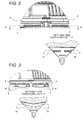
- FIG. 2 to FIG. 5 are expanded views of filter portions seen from the outside, the filter portions having configurations different from each other.
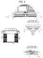
- FIG. 6 shows an example of an electronic control device having a configuration including a metal base and a resin cover, and shows views of a configuration in which the resin cover is provided with a filter portion.
- a view on arrow J is an expanded view of a filter portion seen from the outside, the filter portion being provided at a corner portion of the resin cover.
- the sectional view is a part of the section taken along line K-K.
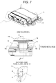
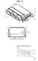
- FIG. 7 to FIG. 9 are expanded views of filter portions seen from the outside, the filter portions having configurations different from each other.
- FIG. 10 and FIG. 11 are sectional views showing the effect of the present invention that parts can be mounted also on a board below a filter portion.
- FIG. 1 shows First Example of the present invention.
- a heat conductive material 4b is interposed, and the circuit board 4 is fixed to the metal cover 2 by a circuit board fixing screw 6.
- the metal cover 2 and the resin base 3 are joined at heat caulking portions 3a obtained by thermally molding bosses provided at corner parts of the resin base 3.
- the metal cover 2 and the resin base 3 may be joined by other method such as using a screw or a rivet.
- a breathing filter film 7 is provided at a corner portion of the resin base 3. The filter may be provided at any corner portion.
- Methods of attaching the filter film 7 to the resin base 3 include heat-welding, bonding with an adhesive, adhesion by an adhesive tape, integral molding with the resin base 3, and the like.
- Breathing paths 8 are opened in surfaces sandwiching a filter portion at the corner portion (breathing path opening surfaces 9) and are connected to each other inside.
- a breathing hole 11 is provided below the filter film 7, to communicate with the breathing path 8.
- an attachment position of the filter film 7 is set based on a positional relationship between the breathing path 8 and the breathing hole 11 so as not to be seen from the outside in order to prevent high pressure water from splashing the filter film 7. Since the filter film 7 and the breathing path 8 are thin relative to a thickness of the case, the filter portion can be configured to be thin as a whole. Therefore, as shown in FIG. 10 , a clearance with the circuit board 4 can be made large to enable the electronic part 4a to be mounted above the filter portion.
- FIG. 2 shows Second Example of the present invention.
- at least one rib 10 is formed in a breathing path 8 in order to ensure strength. It is necessary to provide the rib 10 because as an opening area of the breathing path 8 is increased, the strength of the filter portion is decreased.
- the rib 10 serves also as a protective wall for preventing high pressure water from splashing a filter film 7.
- the filter portion since the filter portion has a small thickness, parts can be mounted also on the board above the filter portion.
- FIG. 3 shows Third Example of the present invention.
- a rib has a different shape.
- the filter has a small thickness to enable parts to be mounted also on the board above the filter portion. Additionally, an opening area of a breathing path 8 of a resin base 3 is decreased to suppress an inflow of high pressure water. Further, since a rib 10 is angled, the force of inflowing high pressure water, which hits against a wall surface, is dispersed to reduce a pressure applied to a breathing filter film 7.
- FIG. 4 shows Fourth Example of the present invention.
- the insides of breathing paths formed in respective surfaces sandwiching a filter portion are angled to cross with each other within a base in order to improve drainability.
- the filter has a small thickness to enable parts to be mounted also on a board above the filter portion. Additionally, having an angle 12 facilitates discharging of entering high pressure water at whichever angle the electronic control device of the present invention is arranged.
- FIG. 5 shows Fifth Example of the present invention.
- a bottom surface of a breathing path of a resin base 2 has a slanting portion 13 in order to improve drainability.
- a filter film 7 is set based on a positional relationship between breathing paths 8 and a breathing hole 11 so as not to be seen from the outside in order to prevent high pressure water from splashing the filter film 7.
- the filter portion has a small thickness to enable parts to be mounted also on a board above the filter portion.
- FIG. 6 shows Sixth Example of the present invention.
- a resin cover 14 and a metal base 15 are used.
- a heat conductive material 4b is interposed, and the circuit board 4 is fixed to the metal base 15 by a circuit board fixing screw 6.
- the resin cover 14 and the metal base 15 are joined by heat caulking bosses provided at the four corners of the resin cover 14.
- the resin cover 14 and the metal base 15 may be fixed by other method such as using a screw or a rivet.
- a filter film 7 is provided at the corner portion of the resin cover 14.
- the filter may be provided at any corner portion.
- Methods of attaching the filter film 7 to the resin cover 14 include heat-welding, bonding with an adhesive, adhesion by an adhesive tape, integral molding with the resin cover 14, and the like.
- Breathing paths 8 are opened in surfaces sandwiching a filter portion at the corner portion and are connected to each other inside.
- a breathing hole 11 is provided to communicate with the breathing path 8.
- the filter film 7 is set based on a positional relationship between the breathing path 8 and the breathing hole 11 so as not to be seen from the outside in order to prevent high pressure water from splashing the filter film 7.
- the filter portion can be configured to be thin. Therefore, as shown in FIG. 11 , a clearance with the circuit board 4 can be made large to enable the electronic part 4a to be mounted below the filter portion.
- FIG. 7 shows Seventh Example of the present invention.
- a first breathing path 8a is opened from a resin cover upper surface 14a toward a metal base 15
- a second breathing path 8b is opened in a resin cover side surface 14b so as to be perpendicular to the first path, and both paths cross with each other within a resin cover 14.
- a breathing hole 11 is formed at a position at which the first and second breathing paths cross with each other and which is on the inner side of the resin cover 14, and further inside, a breathing filter film 7 is provided.
- the filter film 7 is set based on a positional relationship between the first and second breathing paths 8a and 8b and the breathing hole 11 so as not to be seen from the outside in order to prevent high pressure water from splashing the filter film 7.
- the filter portion has a small thickness, parts can be mounted below the filter portion and on the board as well.
- FIG. 8 shows Eighth Example of the present invention.
- breathing paths 8 are provided in a resin cover upper surface 14a and a resin cover side surface 14b and cross with each other within a resin cover 14.
- the breathing path 8 and a breathing hole 11 cross with each other and a breathing filter film 7 is provided below the breathing hole 11.
- the filter film 7 is set based on a positional relationship with the breathing path 8 so as not to be seen from the outside in order to prevent high pressure water from splashing the filter film 7.
- a filter portion has a small thickness, parts can be mounted below the filter portion and on the board as well.
- FIG. 9 shows Ninth Example of the present invention.
- a first breathing path 8a is formed from a resin cover upper surface 14a toward a metal base 15 and a second breathing path 8b is formed from the outer side of a resin cover side surface 14b toward an inner side of a resin cover 14 so as to cross with each other within the resin base 14.
- the breathing paths 8a and 8b further cross with a breathing hole 11.
- a breathing filter film 7 is provided on an inner side of the breathing hole 11 within the resin cover 14.
- the filter film 7 is set based on a positional relationship with the breathing path 8 so as not to be seen from the outside in order to prevent high pressure water from splashing the filter film 7.
- a filter portion has a small thickness to enable parts to be mounted below the filter portion and on the board as well.
Landscapes
- Engineering & Computer Science (AREA)
- Microelectronics & Electronic Packaging (AREA)
- Mechanical Engineering (AREA)
- General Engineering & Computer Science (AREA)
- Casings For Electric Apparatus (AREA)
- Cooling Or The Like Of Electrical Apparatus (AREA)
- Connection Or Junction Boxes (AREA)
Abstract
Description
- The present invention relates to a case structure for an electronic control device mounted on a vehicle, such as an engine control unit or an automatic transmission control unit, which has a waterproof structure provided with a breathing filter.
- An electronic control device, such as an engine control unit or an automatic transmission control unit, which is mounted under a condition where the unit is directly splashed with liquid such as water, for example, mounted in an engine room, is configured to have a circuit board mounted with electronic parts housed in a protective space (waterproofed space) in a case made up of a plurality of case parts joined. In such an electronic control device, completely sealing a case causes stress to be applied to a harness connected to a connector portion and a waterproof portion at the tip of the harness due to a pressure difference between the inside of the case and the outside air, resulting in making liquid such as water be liable to be drawn into the unit. Therefore, a structure has been provided in which a breathing path is provided at a part of a case member and a breathing filter film having permeability and waterproofness is attached to an end surface of the breathing path (e.g. PTL 1).
- PTL 1:
JP 2006-49618 A - However, in a conventional structure of an electronic control device, depending on a direction in which the device is mounted on a vehicle, water stays in a breathing filter portion to disable adjustment of a pressure difference between the inside of a case and the outside air, resulting in limiting a vehicular layout. Additionally, since a filter portion is formed in the central part within the case, no electronic part can be mounted on boards below and above the filter portion, resulting in increasing a board size and a case size. Additionally, a cost-up problem is also involved.
- Therefore, an object of the present invention is to provide an electronic control equipment less limited than a conventional equipment in terms of an equipment mounting direction.
- The above-described problem is solved by the invention recited in Claims.
- For example, breathing paths are provided in surfaces that sandwich a part to which a filter film is welded at a corner portion of a resin-side case of an electronic control device, and these paths are connected to each other inside the case.
- The present invention enables provision of an electronic control equipment less limited than a conventional equipment in terms of an equipment mounting direction.
-
- [
FIG. 1] FIG. 1 shows an external view, and an expanded view and sectional views of a relevant part of an electronic control device according to Example 1. - [
FIG. 2] FIG. 2 shows an expanded view and a sectional view of a relevant part in a filter portion according to Example 2. - [
FIG. 3] FIG. 3 shows an expanded view and a sectional view of a relevant part in a filter portion according to Example 2. - [
FIG. 4] FIG. 4 shows an expanded view and a sectional view of a relevant part in a filter portion according to Example 4. - [
FIG. 5] FIG. 5 shows an expanded view and sectional views of a relevant part in a filter portion according to Example 5. - [
FIG. 6] FIG. 6 shows an external view, and an expanded view and a sectional view of a relevant part of an electronic control device according to Example 6. - [
FIG. 7] FIG. 7 shows an expanded view and sectional views of a relevant part in a filter portion according to Example 7. - [
FIG. 8] FIG. 8 shows expanded views and a sectional view of a relevant part in a filter portion according to Example 8. - [
FIG. 9] FIG. 9 shows expanded views and a sectional view of a relevant part in a filter portion according to Example 9. - [
FIG. 10] FIG. 10 is a sectional view showing that in a configuration including a metal cover and a resin base, an electronic part and the like can be mounted above a filter portion. - [
FIG. 11] FIG. 11 is a sectional view showing that in a configuration including a resin cover and a metal base, an electronic part and the like can be mounted above a filter portion. - In the following, Examples of the present invention will be described with reference to
FIG. 1 to FIG. 4 .FIG. 1 shows an external view and developed views of an electronic control device mounted on a vehicle, such as an engine control unit or an automatic transmission control unit, which adopts a structure of the present Example. A view on arrow A is an expanded view of a filter portion seen from the outside, the filter portion being provided at a corner portion of a resin base. Additionally, the sectional views show sections of parts taken along line B-B, line C-C and line D-D, respectively.FIG. 2 to FIG. 5 are expanded views of filter portions seen from the outside, the filter portions having configurations different from each other.FIG. 6 shows an example of an electronic control device having a configuration including a metal base and a resin cover, and shows views of a configuration in which the resin cover is provided with a filter portion. - A view on arrow J is an expanded view of a filter portion seen from the outside, the filter portion being provided at a corner portion of the resin cover. The sectional view is a part of the section taken along line K-K.
FIG. 7 to FIG. 9 are expanded views of filter portions seen from the outside, the filter portions having configurations different from each other.FIG. 10 and FIG. 11 are sectional views showing the effect of the present invention that parts can be mounted also on a board below a filter portion. -
FIG. 1 shows First Example of the present invention. - In the present Example, between an
electronic part 4a mounted on acircuit board 4 and a metal cover 2 (die-cast), a heatconductive material 4b is interposed, and thecircuit board 4 is fixed to the metal cover 2 by a circuitboard fixing screw 6. For maintaining waterproofness of a case, with an adhesive 5 interposed among a connector forexternal connection 1, the metal cover 2 and aresin base 3, the metal cover 2 and theresin base 3 are joined at heat caulkingportions 3a obtained by thermally molding bosses provided at corner parts of theresin base 3. The metal cover 2 and theresin base 3 may be joined by other method such as using a screw or a rivet. At a corner portion of theresin base 3, abreathing filter film 7 is provided. The filter may be provided at any corner portion. Methods of attaching thefilter film 7 to theresin base 3 include heat-welding, bonding with an adhesive, adhesion by an adhesive tape, integral molding with theresin base 3, and the like.Breathing paths 8 are opened in surfaces sandwiching a filter portion at the corner portion (breathing path opening surfaces 9) and are connected to each other inside. Below thefilter film 7, abreathing hole 11 is provided to communicate with thebreathing path 8. In this case, an attachment position of thefilter film 7 is set based on a positional relationship between thebreathing path 8 and thebreathing hole 11 so as not to be seen from the outside in order to prevent high pressure water from splashing thefilter film 7. Since thefilter film 7 and thebreathing path 8 are thin relative to a thickness of the case, the filter portion can be configured to be thin as a whole. Therefore, as shown inFIG. 10 , a clearance with thecircuit board 4 can be made large to enable theelectronic part 4a to be mounted above the filter portion. -
FIG. 2 shows Second Example of the present invention. As compared with the above Example 1, at least onerib 10 is formed in abreathing path 8 in order to ensure strength. It is necessary to provide therib 10 because as an opening area of thebreathing path 8 is increased, the strength of the filter portion is decreased. In addition to ensuring the strength, therib 10 serves also as a protective wall for preventing high pressure water from splashing afilter film 7. Similarly to Example 1, since the filter portion has a small thickness, parts can be mounted also on the board above the filter portion. -
FIG. 3 shows Third Example of the present invention. As compared with the above Example 2, a rib has a different shape. Similarly to Example 1, the filter has a small thickness to enable parts to be mounted also on the board above the filter portion. Additionally, an opening area of abreathing path 8 of aresin base 3 is decreased to suppress an inflow of high pressure water. Further, since arib 10 is angled, the force of inflowing high pressure water, which hits against a wall surface, is dispersed to reduce a pressure applied to abreathing filter film 7. -
FIG. 4 shows Fourth Example of the present invention. As compared with the above Examples 1 to 3, the insides of breathing paths formed in respective surfaces sandwiching a filter portion are angled to cross with each other within a base in order to improve drainability. Similarly to Example 1 to Example 3, the filter has a small thickness to enable parts to be mounted also on a board above the filter portion. Additionally, having anangle 12 facilitates discharging of entering high pressure water at whichever angle the electronic control device of the present invention is arranged. -
FIG. 5 shows Fifth Example of the present invention. As compared with the above Example 1 to Example 4, a bottom surface of a breathing path of a resin base 2 has a slantingportion 13 in order to improve drainability. In this case, afilter film 7 is set based on a positional relationship betweenbreathing paths 8 and abreathing hole 11 so as not to be seen from the outside in order to prevent high pressure water from splashing thefilter film 7. Similarly to Example 1 to Example 4, the filter portion has a small thickness to enable parts to be mounted also on a board above the filter portion. -
FIG. 6 shows Sixth Example of the present invention. As compared with the above Example 1, aresin cover 14 and ametal base 15 are used. In the present Example, between anelectronic part 4a mounted on acircuit board 4 and themetal base 3, a heatconductive material 4b is interposed, and thecircuit board 4 is fixed to themetal base 15 by a circuitboard fixing screw 6. For maintaining waterproofness of a case, with an adhesive 5 interposed among a connector forexternal connection 1, theresin cover 14 and themetal base 15, the cover and the base are joined by heat caulking bosses provided at the four corners of theresin cover 14. Theresin cover 14 and themetal base 15 may be fixed by other method such as using a screw or a rivet. In this case, at the corner portion of theresin cover 14, afilter film 7 is provided. The filter may be provided at any corner portion. Methods of attaching thefilter film 7 to theresin cover 14 include heat-welding, bonding with an adhesive, adhesion by an adhesive tape, integral molding with theresin cover 14, and the like.Breathing paths 8 are opened in surfaces sandwiching a filter portion at the corner portion and are connected to each other inside. Below thefilter film 7, abreathing hole 11 is provided to communicate with thebreathing path 8. In this case, thefilter film 7 is set based on a positional relationship between thebreathing path 8 and thebreathing hole 11 so as not to be seen from the outside in order to prevent high pressure water from splashing thefilter film 7. Since thefilter film 7 and thebreathing path 8 are thin relative to a thickness of the case, the filter portion can be configured to be thin. Therefore, as shown inFIG. 11 , a clearance with thecircuit board 4 can be made large to enable theelectronic part 4a to be mounted below the filter portion. -
FIG. 7 shows Seventh Example of the present invention. As compared with the above Example 6, afirst breathing path 8a is opened from a resin coverupper surface 14a toward ametal base 15, asecond breathing path 8b is opened in a resincover side surface 14b so as to be perpendicular to the first path, and both paths cross with each other within aresin cover 14. Abreathing hole 11 is formed at a position at which the first and second breathing paths cross with each other and which is on the inner side of theresin cover 14, and further inside, abreathing filter film 7 is provided. In this case, thefilter film 7 is set based on a positional relationship between the first andsecond breathing paths breathing hole 11 so as not to be seen from the outside in order to prevent high pressure water from splashing thefilter film 7. Similarly to Example 6, since the filter portion has a small thickness, parts can be mounted below the filter portion and on the board as well. -
FIG. 8 shows Eighth Example of the present invention. As compared with the above Example 6, in order to improve drainability, at a resin cover upper surface corner portion 14c,breathing paths 8 are provided in a resin coverupper surface 14a and a resincover side surface 14b and cross with each other within aresin cover 14. Thebreathing path 8 and abreathing hole 11 cross with each other and abreathing filter film 7 is provided below thebreathing hole 11. In this case, thefilter film 7 is set based on a positional relationship with thebreathing path 8 so as not to be seen from the outside in order to prevent high pressure water from splashing thefilter film 7. Similarly to Example 6, since a filter portion has a small thickness, parts can be mounted below the filter portion and on the board as well. -
FIG. 9 shows Ninth Example of the present invention. As compared with the above Example 8, in order to improve drainability, at a resin cover upper surface corner portion 14c, afirst breathing path 8a is formed from a resin coverupper surface 14a toward ametal base 15 and asecond breathing path 8b is formed from the outer side of a resincover side surface 14b toward an inner side of aresin cover 14 so as to cross with each other within theresin base 14. Thebreathing paths breathing hole 11. Abreathing filter film 7 is provided on an inner side of thebreathing hole 11 within theresin cover 14. In this case, thefilter film 7 is set based on a positional relationship with thebreathing path 8 so as not to be seen from the outside in order to prevent high pressure water from splashing thefilter film 7. Similarly to Example 6, a filter portion has a small thickness to enable parts to be mounted below the filter portion and on the board as well. - As described in the foregoing, according the present Examples, since water is unlikely to stay in an electronic control equipment irrespectively of a direction, flexibility of layout for mounting the equipment on a vehicle can be increased. Additionally, since arrangement of the filter portion at the case corner portion ensures a clearance between the filter portion and the board, a board fixing structure such as a screw, and an electronic part can be arranged to enable an effect of preventing an increase in a board size to be obtained.
-
- 1
- connector for external connection
- 2
- metal cover
- 3
- resin base
- 3a
- heat caulking portion
- 4
- circuit board
- 4a
- electronic part
- 4b
- heat conductive material
- 5
- adhesive
- 6
- circuit board fixing screw
- 7
- breathing filter film
- 8
- breathing path
- 8a
- first breathing path
- 8b
- second breathing path
- 9
- breathing path opening surface
- 10
- rib
- 11
- breathing hole
- 12
- angle
- 13
- slanting portion
- 14
- resin cover
- 14a
- resin cover upper surface
- 14b
- resin cover side surface
- 14c
- resin cover upper surface corner portion
- 15
- metal base
Claims (8)
- An electronic control device mounted on a vehicle, comprising:a circuit board mounted with an electronic part;a case made of resin as a part of a case covering the circuit board; anda breathing portion having a filter film disposed between the inside and the outside of the case covering the circuit board, whereinthe breathing portion is provided at a corner portion of the case made of resin and has breathing paths in respective surfaces of the case made of resin which sandwich the breathing portion, the breathing paths communicating with each other within the case made of resin.
- The electronic control device according to claim 1, wherein a rib is provided in the breathing path.
- The electronic control device according to claim 1, wherein the breathing paths are angled and communicate with each other within the case made of resin.
- The electronic control device according to claim 1, wherein the case made of resin is a resin base, and a bottom surface of the breathing path of the resin base has a slanting portion.
- The electronic control device according to claim 1, wherein the case made of resin is a resin cover.
- The electronic control device according to claim 5, wherein the breathing path is provided from an upper surface corner portion of the resin cover toward a metal base and communicates with breathing paths in a side surface and a back surface of the resin cover.
- The electronic control device according to claim 5, wherein the breathing path is provided in the upper surface of the resin cover and communicates with a breathing path in the side surface or the back surface, or in both the side and back surfaces of the resin cover within the resin cover.
- The electronic control device according to claim 5, wherein the breathing path is provided from the upper surface of the resin cover toward a metal base and communicates with a breathing path in the side surface or the back surface of the resin cover within the resin cover.
Priority Applications (1)
| Application Number | Priority Date | Filing Date | Title |
|---|---|---|---|
| EP19208844.1A EP3641512B1 (en) | 2013-12-05 | 2014-11-12 | Case structure for electronic control device |
Applications Claiming Priority (2)
| Application Number | Priority Date | Filing Date | Title |
|---|---|---|---|
| JP2013251608 | 2013-12-05 | ||
| PCT/JP2014/079901 WO2015083507A1 (en) | 2013-12-05 | 2014-11-12 | Case structure for electronic control device |
Related Child Applications (2)
| Application Number | Title | Priority Date | Filing Date |
|---|---|---|---|
| EP19208844.1A Division EP3641512B1 (en) | 2013-12-05 | 2014-11-12 | Case structure for electronic control device |
| EP19208844.1A Division-Into EP3641512B1 (en) | 2013-12-05 | 2014-11-12 | Case structure for electronic control device |
Publications (3)
| Publication Number | Publication Date |
|---|---|
| EP3079449A1 true EP3079449A1 (en) | 2016-10-12 |
| EP3079449A4 EP3079449A4 (en) | 2017-11-29 |
| EP3079449B1 EP3079449B1 (en) | 2020-01-08 |
Family
ID=53273277
Family Applications (2)
| Application Number | Title | Priority Date | Filing Date |
|---|---|---|---|
| EP19208844.1A Active EP3641512B1 (en) | 2013-12-05 | 2014-11-12 | Case structure for electronic control device |
| EP14868328.7A Active EP3079449B1 (en) | 2013-12-05 | 2014-11-12 | Case structure for electronic control device |
Family Applications Before (1)
| Application Number | Title | Priority Date | Filing Date |
|---|---|---|---|
| EP19208844.1A Active EP3641512B1 (en) | 2013-12-05 | 2014-11-12 | Case structure for electronic control device |
Country Status (5)
| Country | Link |
|---|---|
| US (2) | US9894785B2 (en) |
| EP (2) | EP3641512B1 (en) |
| JP (2) | JP6275163B2 (en) |
| CN (1) | CN105794327B (en) |
| WO (1) | WO2015083507A1 (en) |
Families Citing this family (9)
| Publication number | Priority date | Publication date | Assignee | Title |
|---|---|---|---|---|
| US10238012B2 (en) * | 2013-10-02 | 2019-03-19 | Hitachi Automotive Systems, Ltd | Waterproof component-suppressing electronic control device |
| DE102015206616A1 (en) * | 2015-04-14 | 2016-10-20 | Zf Friedrichshafen Ag | Printed circuit board for electronic function control for a vehicle |
| US20170210307A1 (en) * | 2016-01-22 | 2017-07-27 | Toyota Motor Engineering & Manufacturing North America, Inc. | Attachment for electrical components |
| JP6113314B1 (en) * | 2016-02-01 | 2017-04-12 | 三菱電機株式会社 | Waterproof control device |
| CN106004713A (en) * | 2016-06-28 | 2016-10-12 | 天津雷沃动力有限公司 | Protective structure for engine electronic control unit |
| JP6521934B2 (en) * | 2016-12-16 | 2019-05-29 | 本田技研工業株式会社 | Electronic device |
| JP7114918B2 (en) * | 2018-02-06 | 2022-08-09 | 株式会社デンソー | electronic controller |
| JP2019216171A (en) * | 2018-06-12 | 2019-12-19 | 株式会社ジェイテクト | Control device |
| CN110329179B (en) * | 2019-07-15 | 2020-06-09 | 广州威尔森信息科技有限公司 | Local distributed vehicle-mounted terminal scheduling system and method |
Family Cites Families (22)
| Publication number | Priority date | Publication date | Assignee | Title |
|---|---|---|---|---|
| JPH0682884U (en) | 1993-04-28 | 1994-11-25 | 富士通テン株式会社 | Case |
| DE59800974D1 (en) * | 1997-11-28 | 2001-08-09 | Siemens Ag | VENTILATION DEVICE, ESPECIALLY FOR ELECTRICAL CONTROL UNITS |
| CA2351543C (en) * | 1999-09-16 | 2009-07-07 | Tokai Kogyo Co., Ltd. | Resin case in which gas-permeability and waterproof quality are compatible, and die for manufacturing such case |
| JP3669276B2 (en) * | 2001-02-21 | 2005-07-06 | 株式会社デンソー | Case for electronic control device and electronic control device |
| US6628523B2 (en) * | 2001-02-08 | 2003-09-30 | Denso Corporation | Casing for electronic control unit |
| JP2005132165A (en) * | 2003-10-29 | 2005-05-26 | Nsk Ltd | Electric power steering device |
| JP2006005162A (en) * | 2004-06-17 | 2006-01-05 | Denso Corp | Waterproof case for electronic equipment |
| JP4431003B2 (en) * | 2004-07-29 | 2010-03-10 | パナソニック株式会社 | Electronic equipment |
| JP4310249B2 (en) | 2004-08-05 | 2009-08-05 | 三菱電機株式会社 | Electronic control unit |
| JP4443386B2 (en) * | 2004-11-09 | 2010-03-31 | 三菱電機株式会社 | Electronic control equipment |
| JP4835418B2 (en) * | 2005-12-14 | 2011-12-14 | 株式会社デンソー | Waterproof structure |
| EP1799021B1 (en) * | 2005-12-14 | 2012-06-06 | Denso Corporation | Waterproof case |
| JP4858778B2 (en) | 2007-01-31 | 2012-01-18 | 株式会社ノーリツ | Audio equipment |
| JP5094644B2 (en) | 2008-08-29 | 2012-12-12 | 日立オートモティブシステムズ株式会社 | Electronic control device |
| JP2010147208A (en) * | 2008-12-18 | 2010-07-01 | Nec Corp | Electronic apparatus storing container and assembly method of the same |
| JP5147782B2 (en) * | 2009-05-26 | 2013-02-20 | 古野電気株式会社 | Housing case, fluid flow velocity reduction structure, and marine electronic equipment |
| JP5016072B2 (en) * | 2010-02-05 | 2012-09-05 | 三菱電機株式会社 | Waterproof enclosure |
| JP5434669B2 (en) * | 2010-02-26 | 2014-03-05 | 株式会社デンソー | Waterproof housing and waterproof device |
| JP2013069736A (en) | 2011-09-21 | 2013-04-18 | Hitachi Automotive Systems Ltd | Electronic control device |
| JP5796485B2 (en) * | 2011-12-28 | 2015-10-21 | 株式会社ノーリツ | Remote controller |
| DE102012203389A1 (en) * | 2012-03-05 | 2013-09-05 | Robert Bosch Gmbh | Pressure equalization element for control device of motor car, has channels that are respectively extended from primary and secondary chambers towards the surface of base portion |
| JP2015177140A (en) * | 2014-03-18 | 2015-10-05 | 日立オートモティブシステムズ株式会社 | Electronic controller |
-
2014
- 2014-11-12 EP EP19208844.1A patent/EP3641512B1/en active Active
- 2014-11-12 CN CN201480065798.6A patent/CN105794327B/en active Active
- 2014-11-12 US US15/038,608 patent/US9894785B2/en active Active
- 2014-11-12 EP EP14868328.7A patent/EP3079449B1/en active Active
- 2014-11-12 JP JP2015551443A patent/JP6275163B2/en active Active
- 2014-11-12 WO PCT/JP2014/079901 patent/WO2015083507A1/en active Application Filing
-
2018
- 2018-01-09 JP JP2018000966A patent/JP6423552B2/en active Active
- 2018-01-10 US US15/866,670 patent/US10225939B2/en active Active
Also Published As
| Publication number | Publication date |
|---|---|
| CN105794327B (en) | 2019-01-15 |
| US10225939B2 (en) | 2019-03-05 |
| EP3641512A1 (en) | 2020-04-22 |
| US20160295721A1 (en) | 2016-10-06 |
| WO2015083507A1 (en) | 2015-06-11 |
| EP3079449B1 (en) | 2020-01-08 |
| EP3079449A4 (en) | 2017-11-29 |
| JP6423552B2 (en) | 2018-11-14 |
| US20180132366A1 (en) | 2018-05-10 |
| US9894785B2 (en) | 2018-02-13 |
| JPWO2015083507A1 (en) | 2017-03-16 |
| JP2018067735A (en) | 2018-04-26 |
| CN105794327A (en) | 2016-07-20 |
| JP6275163B2 (en) | 2018-02-07 |
| EP3641512B1 (en) | 2021-02-17 |
Similar Documents
| Publication | Publication Date | Title |
|---|---|---|
| US10225939B2 (en) | Case structure for electronic control device | |
| US9093776B2 (en) | Electronic control device | |
| CN103025105B (en) | Sealing structure for electronic-controlled installation | |
| US9340168B2 (en) | Electronic apparatus for vehicle | |
| US9013889B2 (en) | Electronic controller | |
| EP3188578B1 (en) | Electronic control device | |
| US8157116B2 (en) | Electrical junction box | |
| WO2014050591A1 (en) | Electronic control device | |
| US20130070432A1 (en) | Seal Structure for Electronic Control Device | |
| EP3247013A1 (en) | Electronic control device | |
| JP2013069736A (en) | Electronic control device | |
| JP2014209639A (en) | Electronic control device | |
| JP4743158B2 (en) | Waterproof ventilation case device | |
| JP6346048B2 (en) | Electronic control unit | |
| US9692221B2 (en) | Junction box and contactor device | |
| JP2015153595A (en) | On-vehicle electrical equipment, and method of manufacturing the same | |
| US20130327566A1 (en) | Electrical junction box | |
| JP2016152369A (en) | Electronic control unit | |
| CN104425436A (en) | Semiconductor device and flexible circuit board | |
| JP4798394B2 (en) | Case for electrical equipment | |
| JP2013158182A (en) | Waterproof structure of electronic unit | |
| JP2013106398A (en) | Circuit unit |
Legal Events
| Date | Code | Title | Description |
|---|---|---|---|
| PUAI | Public reference made under article 153(3) epc to a published international application that has entered the european phase |
Free format text: ORIGINAL CODE: 0009012 |
|
| 17P | Request for examination filed |
Effective date: 20160705 |
|
| AK | Designated contracting states |
Kind code of ref document: A1 Designated state(s): AL AT BE BG CH CY CZ DE DK EE ES FI FR GB GR HR HU IE IS IT LI LT LU LV MC MK MT NL NO PL PT RO RS SE SI SK SM TR |
|
| AX | Request for extension of the european patent |
Extension state: BA ME |
|
| DAX | Request for extension of the european patent (deleted) | ||
| A4 | Supplementary search report drawn up and despatched |
Effective date: 20171027 |
|
| RIC1 | Information provided on ipc code assigned before grant |
Ipc: H05K 5/00 20060101ALI20171023BHEP Ipc: H05K 5/02 20060101ALI20171023BHEP Ipc: B60R 16/02 20060101ALI20171023BHEP Ipc: H05K 5/06 20060101AFI20171023BHEP Ipc: B60R 16/023 20060101ALI20171023BHEP |
|
| STAA | Information on the status of an ep patent application or granted ep patent |
Free format text: STATUS: EXAMINATION IS IN PROGRESS |
|
| 17Q | First examination report despatched |
Effective date: 20181001 |
|
| GRAP | Despatch of communication of intention to grant a patent |
Free format text: ORIGINAL CODE: EPIDOSNIGR1 |
|
| STAA | Information on the status of an ep patent application or granted ep patent |
Free format text: STATUS: GRANT OF PATENT IS INTENDED |
|
| INTG | Intention to grant announced |
Effective date: 20190703 |
|
| GRAS | Grant fee paid |
Free format text: ORIGINAL CODE: EPIDOSNIGR3 |
|
| GRAA | (expected) grant |
Free format text: ORIGINAL CODE: 0009210 |
|
| STAA | Information on the status of an ep patent application or granted ep patent |
Free format text: STATUS: THE PATENT HAS BEEN GRANTED |
|
| AK | Designated contracting states |
Kind code of ref document: B1 Designated state(s): AL AT BE BG CH CY CZ DE DK EE ES FI FR GB GR HR HU IE IS IT LI LT LU LV MC MK MT NL NO PL PT RO RS SE SI SK SM TR |
|
| REG | Reference to a national code |
Ref country code: GB Ref legal event code: FG4D |
|
| REG | Reference to a national code |
Ref country code: CH Ref legal event code: EP |
|
| REG | Reference to a national code |
Ref country code: DE Ref legal event code: R096 Ref document number: 602014059891 Country of ref document: DE |
|
| REG | Reference to a national code |
Ref country code: IE Ref legal event code: FG4D |
|
| REG | Reference to a national code |
Ref country code: AT Ref legal event code: REF Ref document number: 1224347 Country of ref document: AT Kind code of ref document: T Effective date: 20200215 |
|
| REG | Reference to a national code |
Ref country code: NL Ref legal event code: MP Effective date: 20200108 |
|
| REG | Reference to a national code |
Ref country code: LT Ref legal event code: MG4D |
|
| PG25 | Lapsed in a contracting state [announced via postgrant information from national office to epo] |
Ref country code: NL Free format text: LAPSE BECAUSE OF FAILURE TO SUBMIT A TRANSLATION OF THE DESCRIPTION OR TO PAY THE FEE WITHIN THE PRESCRIBED TIME-LIMIT Effective date: 20200108 Ref country code: RS Free format text: LAPSE BECAUSE OF FAILURE TO SUBMIT A TRANSLATION OF THE DESCRIPTION OR TO PAY THE FEE WITHIN THE PRESCRIBED TIME-LIMIT Effective date: 20200108 Ref country code: LT Free format text: LAPSE BECAUSE OF FAILURE TO SUBMIT A TRANSLATION OF THE DESCRIPTION OR TO PAY THE FEE WITHIN THE PRESCRIBED TIME-LIMIT Effective date: 20200108 Ref country code: FI Free format text: LAPSE BECAUSE OF FAILURE TO SUBMIT A TRANSLATION OF THE DESCRIPTION OR TO PAY THE FEE WITHIN THE PRESCRIBED TIME-LIMIT Effective date: 20200108 Ref country code: PT Free format text: LAPSE BECAUSE OF FAILURE TO SUBMIT A TRANSLATION OF THE DESCRIPTION OR TO PAY THE FEE WITHIN THE PRESCRIBED TIME-LIMIT Effective date: 20200531 Ref country code: NO Free format text: LAPSE BECAUSE OF FAILURE TO SUBMIT A TRANSLATION OF THE DESCRIPTION OR TO PAY THE FEE WITHIN THE PRESCRIBED TIME-LIMIT Effective date: 20200408 |
|
| PG25 | Lapsed in a contracting state [announced via postgrant information from national office to epo] |
Ref country code: LV Free format text: LAPSE BECAUSE OF FAILURE TO SUBMIT A TRANSLATION OF THE DESCRIPTION OR TO PAY THE FEE WITHIN THE PRESCRIBED TIME-LIMIT Effective date: 20200108 Ref country code: SE Free format text: LAPSE BECAUSE OF FAILURE TO SUBMIT A TRANSLATION OF THE DESCRIPTION OR TO PAY THE FEE WITHIN THE PRESCRIBED TIME-LIMIT Effective date: 20200108 Ref country code: BG Free format text: LAPSE BECAUSE OF FAILURE TO SUBMIT A TRANSLATION OF THE DESCRIPTION OR TO PAY THE FEE WITHIN THE PRESCRIBED TIME-LIMIT Effective date: 20200408 Ref country code: IS Free format text: LAPSE BECAUSE OF FAILURE TO SUBMIT A TRANSLATION OF THE DESCRIPTION OR TO PAY THE FEE WITHIN THE PRESCRIBED TIME-LIMIT Effective date: 20200508 Ref country code: GR Free format text: LAPSE BECAUSE OF FAILURE TO SUBMIT A TRANSLATION OF THE DESCRIPTION OR TO PAY THE FEE WITHIN THE PRESCRIBED TIME-LIMIT Effective date: 20200409 Ref country code: HR Free format text: LAPSE BECAUSE OF FAILURE TO SUBMIT A TRANSLATION OF THE DESCRIPTION OR TO PAY THE FEE WITHIN THE PRESCRIBED TIME-LIMIT Effective date: 20200108 |
|
| REG | Reference to a national code |
Ref country code: DE Ref legal event code: R097 Ref document number: 602014059891 Country of ref document: DE |
|
| PG25 | Lapsed in a contracting state [announced via postgrant information from national office to epo] |
Ref country code: SK Free format text: LAPSE BECAUSE OF FAILURE TO SUBMIT A TRANSLATION OF THE DESCRIPTION OR TO PAY THE FEE WITHIN THE PRESCRIBED TIME-LIMIT Effective date: 20200108 Ref country code: SM Free format text: LAPSE BECAUSE OF FAILURE TO SUBMIT A TRANSLATION OF THE DESCRIPTION OR TO PAY THE FEE WITHIN THE PRESCRIBED TIME-LIMIT Effective date: 20200108 Ref country code: EE Free format text: LAPSE BECAUSE OF FAILURE TO SUBMIT A TRANSLATION OF THE DESCRIPTION OR TO PAY THE FEE WITHIN THE PRESCRIBED TIME-LIMIT Effective date: 20200108 Ref country code: DK Free format text: LAPSE BECAUSE OF FAILURE TO SUBMIT A TRANSLATION OF THE DESCRIPTION OR TO PAY THE FEE WITHIN THE PRESCRIBED TIME-LIMIT Effective date: 20200108 Ref country code: ES Free format text: LAPSE BECAUSE OF FAILURE TO SUBMIT A TRANSLATION OF THE DESCRIPTION OR TO PAY THE FEE WITHIN THE PRESCRIBED TIME-LIMIT Effective date: 20200108 Ref country code: RO Free format text: LAPSE BECAUSE OF FAILURE TO SUBMIT A TRANSLATION OF THE DESCRIPTION OR TO PAY THE FEE WITHIN THE PRESCRIBED TIME-LIMIT Effective date: 20200108 Ref country code: CZ Free format text: LAPSE BECAUSE OF FAILURE TO SUBMIT A TRANSLATION OF THE DESCRIPTION OR TO PAY THE FEE WITHIN THE PRESCRIBED TIME-LIMIT Effective date: 20200108 |
|
| PLBE | No opposition filed within time limit |
Free format text: ORIGINAL CODE: 0009261 |
|
| STAA | Information on the status of an ep patent application or granted ep patent |
Free format text: STATUS: NO OPPOSITION FILED WITHIN TIME LIMIT |
|
| REG | Reference to a national code |
Ref country code: AT Ref legal event code: MK05 Ref document number: 1224347 Country of ref document: AT Kind code of ref document: T Effective date: 20200108 |
|
| 26N | No opposition filed |
Effective date: 20201009 |
|
| PG25 | Lapsed in a contracting state [announced via postgrant information from national office to epo] |
Ref country code: AT Free format text: LAPSE BECAUSE OF FAILURE TO SUBMIT A TRANSLATION OF THE DESCRIPTION OR TO PAY THE FEE WITHIN THE PRESCRIBED TIME-LIMIT Effective date: 20200108 Ref country code: IT Free format text: LAPSE BECAUSE OF FAILURE TO SUBMIT A TRANSLATION OF THE DESCRIPTION OR TO PAY THE FEE WITHIN THE PRESCRIBED TIME-LIMIT Effective date: 20200108 |
|
| PG25 | Lapsed in a contracting state [announced via postgrant information from national office to epo] |
Ref country code: SI Free format text: LAPSE BECAUSE OF FAILURE TO SUBMIT A TRANSLATION OF THE DESCRIPTION OR TO PAY THE FEE WITHIN THE PRESCRIBED TIME-LIMIT Effective date: 20200108 Ref country code: PL Free format text: LAPSE BECAUSE OF FAILURE TO SUBMIT A TRANSLATION OF THE DESCRIPTION OR TO PAY THE FEE WITHIN THE PRESCRIBED TIME-LIMIT Effective date: 20200108 |
|
| REG | Reference to a national code |
Ref country code: DE Ref legal event code: R082 Ref document number: 602014059891 Country of ref document: DE Representative=s name: MERH-IP MATIAS ERNY REICHL HOFFMANN PATENTANWA, DE Ref country code: DE Ref legal event code: R081 Ref document number: 602014059891 Country of ref document: DE Owner name: HITACHI ASTEMO, LTD., HITACHINAKA-SHI, JP Free format text: FORMER OWNER: HITACHI AUTOMOTIVE SYSTEMS, LTD., HITACHINAKA-SHI, IBARAKI, JP |
|
| PG25 | Lapsed in a contracting state [announced via postgrant information from national office to epo] |
Ref country code: MC Free format text: LAPSE BECAUSE OF FAILURE TO SUBMIT A TRANSLATION OF THE DESCRIPTION OR TO PAY THE FEE WITHIN THE PRESCRIBED TIME-LIMIT Effective date: 20200108 |
|
| REG | Reference to a national code |
Ref country code: CH Ref legal event code: PL |
|
| GBPC | Gb: european patent ceased through non-payment of renewal fee |
Effective date: 20201112 |
|
| PG25 | Lapsed in a contracting state [announced via postgrant information from national office to epo] |
Ref country code: LU Free format text: LAPSE BECAUSE OF NON-PAYMENT OF DUE FEES Effective date: 20201112 |
|
| REG | Reference to a national code |
Ref country code: BE Ref legal event code: MM Effective date: 20201130 |
|
| PG25 | Lapsed in a contracting state [announced via postgrant information from national office to epo] |
Ref country code: LI Free format text: LAPSE BECAUSE OF NON-PAYMENT OF DUE FEES Effective date: 20201130 Ref country code: CH Free format text: LAPSE BECAUSE OF NON-PAYMENT OF DUE FEES Effective date: 20201130 |
|
| PG25 | Lapsed in a contracting state [announced via postgrant information from national office to epo] |
Ref country code: FR Free format text: LAPSE BECAUSE OF NON-PAYMENT OF DUE FEES Effective date: 20201130 Ref country code: IE Free format text: LAPSE BECAUSE OF NON-PAYMENT OF DUE FEES Effective date: 20201112 |
|
| PG25 | Lapsed in a contracting state [announced via postgrant information from national office to epo] |
Ref country code: GB Free format text: LAPSE BECAUSE OF NON-PAYMENT OF DUE FEES Effective date: 20201112 |
|
| PG25 | Lapsed in a contracting state [announced via postgrant information from national office to epo] |
Ref country code: TR Free format text: LAPSE BECAUSE OF FAILURE TO SUBMIT A TRANSLATION OF THE DESCRIPTION OR TO PAY THE FEE WITHIN THE PRESCRIBED TIME-LIMIT Effective date: 20200108 Ref country code: MT Free format text: LAPSE BECAUSE OF FAILURE TO SUBMIT A TRANSLATION OF THE DESCRIPTION OR TO PAY THE FEE WITHIN THE PRESCRIBED TIME-LIMIT Effective date: 20200108 Ref country code: CY Free format text: LAPSE BECAUSE OF FAILURE TO SUBMIT A TRANSLATION OF THE DESCRIPTION OR TO PAY THE FEE WITHIN THE PRESCRIBED TIME-LIMIT Effective date: 20200108 |
|
| PG25 | Lapsed in a contracting state [announced via postgrant information from national office to epo] |
Ref country code: MK Free format text: LAPSE BECAUSE OF FAILURE TO SUBMIT A TRANSLATION OF THE DESCRIPTION OR TO PAY THE FEE WITHIN THE PRESCRIBED TIME-LIMIT Effective date: 20200108 Ref country code: AL Free format text: LAPSE BECAUSE OF FAILURE TO SUBMIT A TRANSLATION OF THE DESCRIPTION OR TO PAY THE FEE WITHIN THE PRESCRIBED TIME-LIMIT Effective date: 20200108 |
|
| PG25 | Lapsed in a contracting state [announced via postgrant information from national office to epo] |
Ref country code: BE Free format text: LAPSE BECAUSE OF NON-PAYMENT OF DUE FEES Effective date: 20201130 |
|
| PGFP | Annual fee paid to national office [announced via postgrant information from national office to epo] |
Ref country code: DE Payment date: 20230929 Year of fee payment: 10 |