EP3079221B1 - Emergency starting device and emergency starting method - Google Patents
Emergency starting device and emergency starting method Download PDFInfo
- Publication number
- EP3079221B1 EP3079221B1 EP15167725.9A EP15167725A EP3079221B1 EP 3079221 B1 EP3079221 B1 EP 3079221B1 EP 15167725 A EP15167725 A EP 15167725A EP 3079221 B1 EP3079221 B1 EP 3079221B1
- Authority
- EP
- European Patent Office
- Prior art keywords
- super
- capacitor
- accumulator battery
- controller
- engine
- Prior art date
- Legal status (The legal status is an assumption and is not a legal conclusion. Google has not performed a legal analysis and makes no representation as to the accuracy of the status listed.)
- Active
Links
Images


Classifications
-
- F—MECHANICAL ENGINEERING; LIGHTING; HEATING; WEAPONS; BLASTING
- F02—COMBUSTION ENGINES; HOT-GAS OR COMBUSTION-PRODUCT ENGINE PLANTS
- F02N—STARTING OF COMBUSTION ENGINES; STARTING AIDS FOR SUCH ENGINES, NOT OTHERWISE PROVIDED FOR
- F02N11/00—Starting of engines by means of electric motors
- F02N11/14—Starting of engines by means of electric starters with external current supply
-
- H—ELECTRICITY
- H02—GENERATION; CONVERSION OR DISTRIBUTION OF ELECTRIC POWER
- H02J—CIRCUIT ARRANGEMENTS OR SYSTEMS FOR SUPPLYING OR DISTRIBUTING ELECTRIC POWER; SYSTEMS FOR STORING ELECTRIC ENERGY
- H02J7/00—Circuit arrangements for charging or depolarising batteries or for supplying loads from batteries
- H02J7/34—Parallel operation in networks using both storage and other dc sources, e.g. providing buffering
- H02J7/342—The other DC source being a battery actively interacting with the first one, i.e. battery to battery charging
-
- H—ELECTRICITY
- H02—GENERATION; CONVERSION OR DISTRIBUTION OF ELECTRIC POWER
- H02J—CIRCUIT ARRANGEMENTS OR SYSTEMS FOR SUPPLYING OR DISTRIBUTING ELECTRIC POWER; SYSTEMS FOR STORING ELECTRIC ENERGY
- H02J7/00—Circuit arrangements for charging or depolarising batteries or for supplying loads from batteries
- H02J7/34—Parallel operation in networks using both storage and other dc sources, e.g. providing buffering
- H02J7/345—Parallel operation in networks using both storage and other dc sources, e.g. providing buffering using capacitors as storage or buffering devices
-
- F—MECHANICAL ENGINEERING; LIGHTING; HEATING; WEAPONS; BLASTING
- F02—COMBUSTION ENGINES; HOT-GAS OR COMBUSTION-PRODUCT ENGINE PLANTS
- F02N—STARTING OF COMBUSTION ENGINES; STARTING AIDS FOR SUCH ENGINES, NOT OTHERWISE PROVIDED FOR
- F02N11/00—Starting of engines by means of electric motors
- F02N11/08—Circuits or control means specially adapted for starting of engines
- F02N11/0862—Circuits or control means specially adapted for starting of engines characterised by the electrical power supply means, e.g. battery
- F02N11/0866—Circuits or control means specially adapted for starting of engines characterised by the electrical power supply means, e.g. battery comprising several power sources, e.g. battery and capacitor or two batteries
-
- F—MECHANICAL ENGINEERING; LIGHTING; HEATING; WEAPONS; BLASTING
- F02—COMBUSTION ENGINES; HOT-GAS OR COMBUSTION-PRODUCT ENGINE PLANTS
- F02N—STARTING OF COMBUSTION ENGINES; STARTING AIDS FOR SUCH ENGINES, NOT OTHERWISE PROVIDED FOR
- F02N11/00—Starting of engines by means of electric motors
- F02N11/08—Circuits or control means specially adapted for starting of engines
- F02N11/087—Details of the switching means in starting circuits, e.g. relays or electronic switches
-
- F—MECHANICAL ENGINEERING; LIGHTING; HEATING; WEAPONS; BLASTING
- F02—COMBUSTION ENGINES; HOT-GAS OR COMBUSTION-PRODUCT ENGINE PLANTS
- F02N—STARTING OF COMBUSTION ENGINES; STARTING AIDS FOR SUCH ENGINES, NOT OTHERWISE PROVIDED FOR
- F02N11/00—Starting of engines by means of electric motors
- F02N11/12—Starting of engines by means of mobile, e.g. portable, starting sets
-
- F—MECHANICAL ENGINEERING; LIGHTING; HEATING; WEAPONS; BLASTING
- F02—COMBUSTION ENGINES; HOT-GAS OR COMBUSTION-PRODUCT ENGINE PLANTS
- F02N—STARTING OF COMBUSTION ENGINES; STARTING AIDS FOR SUCH ENGINES, NOT OTHERWISE PROVIDED FOR
- F02N11/00—Starting of engines by means of electric motors
- F02N11/08—Circuits or control means specially adapted for starting of engines
- F02N2011/0881—Components of the circuit not provided for by previous groups
- F02N2011/0885—Capacitors, e.g. for additional power supply
-
- F—MECHANICAL ENGINEERING; LIGHTING; HEATING; WEAPONS; BLASTING
- F02—COMBUSTION ENGINES; HOT-GAS OR COMBUSTION-PRODUCT ENGINE PLANTS
- F02N—STARTING OF COMBUSTION ENGINES; STARTING AIDS FOR SUCH ENGINES, NOT OTHERWISE PROVIDED FOR
- F02N11/00—Starting of engines by means of electric motors
- F02N11/08—Circuits or control means specially adapted for starting of engines
- F02N2011/0881—Components of the circuit not provided for by previous groups
- F02N2011/0888—DC/DC converters
-
- F—MECHANICAL ENGINEERING; LIGHTING; HEATING; WEAPONS; BLASTING
- F02—COMBUSTION ENGINES; HOT-GAS OR COMBUSTION-PRODUCT ENGINE PLANTS
- F02N—STARTING OF COMBUSTION ENGINES; STARTING AIDS FOR SUCH ENGINES, NOT OTHERWISE PROVIDED FOR
- F02N2200/00—Parameters used for control of starting apparatus
- F02N2200/04—Parameters used for control of starting apparatus said parameters being related to the starter motor
- F02N2200/043—Starter voltage
-
- F—MECHANICAL ENGINEERING; LIGHTING; HEATING; WEAPONS; BLASTING
- F02—COMBUSTION ENGINES; HOT-GAS OR COMBUSTION-PRODUCT ENGINE PLANTS
- F02N—STARTING OF COMBUSTION ENGINES; STARTING AIDS FOR SUCH ENGINES, NOT OTHERWISE PROVIDED FOR
- F02N2200/00—Parameters used for control of starting apparatus
- F02N2200/04—Parameters used for control of starting apparatus said parameters being related to the starter motor
- F02N2200/046—Energy or power necessary for starting
Definitions
- the present invention relates to emergency starting technique for an engine, and more particularly, to an emergency starting device and an emergency starting method.
- Starting system is used for starting an engine which can be a gasoline engine or a diesel engine. That is to say, it makes an idle engine work.
- engine which can be a gasoline engine or a diesel engine. That is to say, it makes an idle engine work.
- almost all automobile engines and some small-sized farm machinery engines use electrical starting system, wherein accumulator battery is a critical component.
- the accumulator battery should provide a high starting current, which is generally in the range of 200-800Amp. While the performance of the accumulator battery during high rate discharging or in a cold environment is so poor that it may not able to provide a current high enough to start the engine. In addition, due to the performance degradation, the accumulator battery outputs a drastic changing voltage which may power down the starting system and thus the engine can not be started normally. In this case, an emergency starting device is needed. With its two output ends being respectively connected to the two output ends of the accumulator battery, the emergency starting device, which generally includes a battery such as lead-acid battery or lithium battery, substitutes the accumulator battery to output the starting current to start the engine. But the existing emergency devices are usually bulk and heavy, and the batteries in them are same with the accumulator battery used in the automobile, which has only 2-3 years lifetime. They don't function well in cold environment or with insufficient voltage, thus scheduled maintenance is needed to keep them effective.
- WO 2014/200697 discloses a method to decouple battery from high level cranking currents of diesel engines, which comprises charging a capacitor bank to a preselected DC supercapacitor voltage from a battery when said battery is above a preselected battery voltage, switching the supercapacitor bank to a load and switching the battery off the load, starting the engine and supplying initial voltage and current until terminal voltage of the supercapacitor is equal to terminal voltage of the battery, switching the battery into parallel with the supercapacitor, disconnecting the supercapacitor from the load, and recharging the supercapacitor to the preselected DC capacitor voltage.
- the method allows mitigation of stress placed on batteries and improved battery life while reducing the number of dead battery starts for an engine.
- a boost charger is used in WO 2014/200697 (A1 ), which is connected between the batteries and the supercapacitor bank, and a logic controller is used to activate or deactivate the boost charger based on the current in the capacitor circuit and the battery circuit and load as well as the voltage levels of the battery and capacitor.
- WO 2008/124342 discloses methods and systems for supplying power to a load, wherein the starting system for an internal combustion engine comprising a battery, a secondary electric charge storage device, an electric starter motor, a first switch operable to make and break an electrical connection between the battery and the electric starter motor, a second switch operable to make and break an electrical connection between the electric starter motor and the secondary electric charge storage device after a predetermined time delay, an a charging circuit configured to charge the secondary electric charge storage device in response to a voltage of the secondary electric charge storage device; and the method of starting an engine comprises the steps of supplying electrical energy to an engine starter motor from a battery, supplying electrical energy to the engine starter motor from an electric charge storage device, starting the engine, monitoring the terminal voltage of the electric charge storage device after the engine starts and charging the electric charge storage device while the terminal voltage of the electric charge storage device is less than a predetermined threshold.
- the methods and the systems allow the secondary power source, such as a supercapacitor, be isolated from the primary power source except during the starting event
- the primary power source in WO 2008/124342 is a battery.
- An isolator control module making and breaking the electrical connection between the electric starter motor and the supercapacitor is used to receive the voltage on the battery bus which will decrease at the time when the contacts of starter contactor close, and to begin a start-up delay of approximately thirty milliseconds at the instant when the starter relay contacts close.
- Both the battery in WO 2014/200697 (A1 ) and WO 2008/124342 (A1 ) are functioned to power the motor to start it.
- the battery will power the motor after the supercapacitor powering the motor for a period of time and in WO 2008/124342 (A1 ), the battery will power the motor for a period of time before the supercapacitor powering the motor. So it is required that the battery in WO 2014/200697 (A1 ) and WO 2008/124342 (A1 ) function well, and a battery having performance degradation cannot be used as shown in WO 2014/200697 (A1 ) and WO 2008/124342 (A1 ). Generally, the battery having performance degradation is not depleted and the energy stored in it should be used somehow.
- the invention aims to provide an emergency starting device and an emergency starting method to start the engine in emergency with the energy stored in a super-capacitor thereof.
- the invention provides an emergency starting device according to claim 1 or 2.
- the invention further provides an emergency starting method according to claim 7.
- the starting system in the following embodiments of the invention is a starting system for gasoline engine, whose starting voltage is generally of 12V and the output voltage of the accumulator battery in it should be of 13-15V.
- the emergency starting device of the invention can be connected to the starting system and substitute the starting system, which is not able to start the engine normally, to start the engine.
- the emergency starting device of the invention has a first output end and a second output end, which are connected to the positive electrode and the negative electrode of the accumulator battery in the starting system respectively.
- the negative electrode of the accumulator battery is grounded.
- the emergency starting device of the invention includes a super-capacitor C1, a controller and a relay K1.
- the super-capacitor is capable of storing energy (or power) and the energy stored in the super-capacitor C1 in this embodiment can start the engine in emergency.
- one end (i.e. one plate) of the super-capacitor C1 is connected to the positive electrode of the accumulator battery via the relay K1, the other end (i.e. the other plate) is grounded.
- the super-capacitor C1 is multiple commercially available super-capacitors connected in series because the voltage of an individual super-capacitor is generally 2.5-2.7V while a voltage of 13V-15V is needed to start an engine whose starting voltage is 12V and a voltage of 26-28V is needed to start an engine whose starting voltage is 24V.
- the relay K1 is a normally open relay.
- One output end of the controller is connected to the relay K1 to output a control signal S1 to control the on and off of the relay K1.
- One input end of the controller is connected to the positive electrode of the accumulator battery to receive the electrical signal form the accumulator battery in real time, for example to receive the signal 100 times per second.
- the signal can be a voltage V1 (as shown in Figure 1 ), and can be a current as well.
- the controller When the controller detects the ignition of the starting system, it sends out the control signal S1 to close the relay K1 to electrically connect the super-capacitor C1 and the accumulator battery, thereby the energy (or power) in the super-capacitor C1 can be outputted to start the engine.
- the controller receives the voltage V1 at the positive electrode of the accumulator battery and sends out the control signal S1 to close the relay K1 to electrically connect the super-capacitor C1 and the accumulator battery when it detects a sudden decrease of the voltage V1, for example the decreasing rate is not less than 2V/s.
- the controller can receive the current at the positive electrode of the accumulator battery by arranging a Hall element to the starting cable of the automobile, for example. The detected current at the cable is the current received at the positive electrode of the accumulator battery. The controller sends out the control signal S1 to close the relay K1 to electrically connect the super-capacitor C1 and the accumulator battery when it detects a sudden increase of the current, for example with an increasing rate of no less than 20A/s.
- the controller can calculate the energy (or power) stored in the super-capacitor C1 and determine whether the energy (or power) is sufficient to start the engine.
- the starting current for a small car is about 200A and with a duration time of 2 seconds.
- V1 is the end voltage of the accumulator battery with a unit of volt
- A is the starting current of the engine with a unit of ampere
- T is the duration time for one starting with a unit of hour
- E1 is the energy with a unit of watt ⁇ hour.
- C is the capacitance of the super-capacitor C1 with a unit of Farad
- V is the end voltage V2 of the super-capacitor C1 with a unit of volt
- E is the energy with a unit of watt ⁇ hour.
- the total energy stored in the super-capacitor C1 formed by N super-capacitors connected in series is N ⁇ E, so the controller can determine whether the energy stored in the super-capacitor C1 is sufficient to start the engine by comparing the total energy of the super-capacitor C1 to the energy E1 needed to start the engine once.
- the total energy of the super-capacitor C1 should not be less than twice of the E1.
- the controller determines that the energy (or power) of the super-capacitor C1 is not sufficient to start the engine and sends out an indicating signal when it determines that the total energy of the super-capacitor C1 is less than the energy E1 needed to start the engine once.
- the indicating signal can be an alarm sent out by a speaker controlled by the controller, light emitted by LED or picture and/or words presented on a screen, to indicate the user that the energy (or power) in the super-capacitor is insufficient and the super-capacitor needs to be charged.
- the controller in the embodiment includes chips, whose circuit is the same with the circuit of the controller shown in Figure 4 , except that the output ends K2_CON and K3_CON for outputting the control signals S2 and S3 are not needed. The detail will be discussed later.
- the controller is set to receive the voltage V2 immediately after the first output end and the second output end of the emergency starting device of the invention are connected to the positive electrode and the negative electrode of the accumulator battery in the starting system, to detect the energy of the super-capacitor C1.
- the controller can be equipped with a switch, which generally is a button.
- a switch which generally is a button.
- the controller functions and can receive signals, process signals and output signals.
- the switch is off, the controller does not function.
- the emergency starting method of the invention in the embodiment includes the following steps:
- the negative electrode of the accumulator battery is grounded, one end of the super-capacitor C1 is connected to the positive electrode of the accumulator battery via the relay K1, and the other end of the super-capacitor C1 is grounded.
- the electrical signal from the accumulator battery is the voltage V1 at its positive electrode.
- the controller receives the voltage V1 at a frequency of 100 times per second.
- the controller receives the electrical signal from the super-capacitor C1 in real time, which is the voltage V2 at the non-grounded end of the super-capacitor C1 specifically.
- the controller receives the voltage V2 at a frequency of 100 times per second.
- the controller calculates the energy stored in the super-capacitor C1 according to the voltage V2 and determines whether the energy is sufficient to start the engine. If the result is that the energy is sufficient to start the engine, the controller sends out the control signal S1 to the relay K1 when the electrical signal from the accumulator battery changed suddenly. If the result is that the energy is insufficient to start the engine, the controller sends out the indicating signal to indicate the user that the energy in the super-capacitor is insufficient and the super-capacitor needs to be charged.
- the emergency starting device of the invention has a first output end and a second output end, which are connected to the positive electrode and the negative electrode of the accumulator battery in the starting system respectively.
- the negative electrode of the accumulator battery is grounded.
- the emergency starting device of the invention includes a super-capacitor C1, a controller, a relay K1 and a DC-DC booster circuit.
- a super-capacitor C1 one end (i.e. one plate) of the super-capacitor C1 is connected to the positive electrode of the accumulator battery via the relay K1, the other end (i.e. the other plate) is grounded.
- the DC-DC booster circuit is connected to the relay K1 in parallel.
- the super-capacitor C1 is multiple commercially available super-capacitors connected in series.
- the relay K1 is a normally open relay.
- the super-capacitor C1 in this embodiment is not required to have energy stored in it but can have energy charged into it with the remaining energy in the accumulator battery by the DC-DC booster circuit.
- the accumulator battery still has a voltage of 8-12V though it cannot perform high current discharging, thus it is possible to transfer the energy (or power) remained in the accumulator battery to the super-capacitor C1 by the DC-DC booster circuit.
- the input current to the DC-DC booster circuit should be less than 20A so the end voltage of the accumulator battery will not drop drastically.
- One output end of the controller is connected to the relay K1 to output a control signal S1 to control the on and off of the relay K1.
- One input end of the controller is connected to the positive electrode of the accumulator battery to receive the electrical signal form the accumulator battery in real time.
- the electrical signal can be the voltage V1 (as shown in Figure 2 ), and can be a current as well.
- the controller receives the voltage V1 at a frequency of 100 times per second.
- another input end of the controller is connected to one end of the super-capacitor C1, specifically to the non-grounded end of the super-capacitor C1, to receive the electrical signal from the super-capacitor C1 in real time, specifically to receive the voltage V2 at the non-grounded end of the super-capacitor C1.
- the controller receives the voltage V2 at a frequency of 100 times per second.
- the controller can calculate the energy (or power) stored in the super-capacitor C1 according to the voltage V2, and determine whether the energy (or power) is sufficient to start the engine.
- the controller detects the ignition of the starting system and determines that the energy (or power) in the super-capacitor C1 is sufficient to start the engine, it sends out the control signal S1 to close the relay K1 to electrically connect the super-capacitor C1 and the accumulator battery, thereby the energy (or power) in the super-capacitor C1 can be outputted to start the engine.
- the controller will send out an indicating signal when it determines that the energy stored in the super-capacitor C1 is insufficient to start the engine after a preset time interval's detection, for example 5 minutes' detection.
- the indicating signal can be an alarm sent out by a speaker controlled by the controller, light emitted by LED or picture and/or words presented on a screen, to indicate the user that the energy (or power) in the super-capacitor is insufficient and the super-capacitor needs to be charged by an outer charger.
- the controller in the embodiment has a same circuit as that of the previous embodiment, and will not be described here.
- the controller is set to receive the voltage V2 immediately after the first output end and the second output end of the emergency starting device of the invention are connected to the positive electrode and the negative electrode of the accumulator battery in the starting system, to detect the energy of the super-capacitor C1.
- the controller can be equipped with a switch, which generally is a button.
- a switch which generally is a button.
- the controller functions and can receive signals, process signals and output signals.
- the switch is off, the controller does not function.
- the emergency starting method of the invention in the embodiment includes the following steps:
- the negative electrode of the accumulator battery is grounded, one end of the super-capacitor C1 is connected to the positive electrode of the accumulator battery via the relay K1, and the other end of the super-capacitor C1 is grounded.
- the electrical signal from the accumulator battery is the voltage V1 at the positive electrode thereof.
- the controller receives the voltage V1 at a frequency of 100 times per second.
- the controller receives the electrical signal from the super-capacitor C1 in real time, which is the voltage V2 at the non-grounded end of the super-capacitor C1 specifically.
- the controller receives the voltage V2 at a frequency of 100 times per second.
- the controller calculates the energy stored in the super-capacitor C1 according to the voltage V2 and determines whether the energy is sufficient to start the engine. If the result is that the energy is sufficient to start the engine, the controller sends out the control signal S1 to the relay K1 when the electrical signal from the accumulator battery changes suddenly.
- the controller sends out the indicating signal to indicate the user that the energy in the super-capacitor is insufficient and the super-capacitor needs to be charged by an outer charger.
- the emergency starting device of the invention has a first output end and a second output end, which are connected to the positive electrode and the negative electrode of the accumulator battery in the starting system respectively.
- the negative electrode of the accumulator battery is grounded.
- the emergency starting device of the invention includes a super-capacitor C1, a controller, a first relay K1, a second relay K2, a third relay K3, a DC-DC booster circuit and a battery pack.
- a super-capacitor C1 one end (i.e. one plate) of the super-capacitor C1 is connected to the positive electrode of the accumulator battery via the relay K1, the other end (i.e. the other plate) is grounded.
- the positive electrode of the battery pack is connected to the non-grounded end of the super-capacitor C1 via the third relay K3 and the DC-DC booster circuit, and its negative electrode is grounded.
- the DC-DC booster circuit is connected to the second relay K2 in series, and the series-connected DC-DC booster circuit and second relay K2 are connected to the first relay K1 in parallel.
- the super-capacitor C1 is multiple commercially available super-capacitors connected in series.
- the first relay K1, the second relay K2 and the third relay K3 are normally open relays.
- the battery pack is a rechargeable battery pack, such as lead-acid battery pack, NI-MH battery pack, lithium battery pack and etc. More preferably, it is an 18650 lithium battery pack.
- the super-capacitor C1 in this embodiment is not required to have energy stored in it but can be charged by the battery pack.
- the battery pack is connected to the super-capacitor C1 via the third relay K3 and the DC-DC booster circuit, and the DC-DC booster circuit can increase the output voltage of the battery pack to charge the super-capacitor C1 when the third relay K3 is closed, the output voltage of the battery pack can be lower than the starting voltage.
- the battery pack can be multiple 18650 lithium battery connected in parallel.
- One output end of the controller is connected to the relay K1 to output a control signal S1 to control the on and off of the first relay K1, another output end of the controller is connected to the second relay K2 to output a control signal S2 to control the on and off of the second relay K2, and the third output end of the controller is connected to the third relay K3 to output a control signal S3 to control the on and off of the third relay K3.
- One input end of the controller is connected to the positive electrode of the accumulator battery to receive the first electrical signal from the accumulator battery in real time.
- the electrical signal can be the voltage V1 (as shown in Figure 3 ), and can be a current as well.
- the controller receives the voltage V1 at a frequency of 100 times per second.
- another input end of the controller is connected to one end of the super-capacitor C1, specifically to the non-grounded end of the super-capacitor C1 to receive the second electrical signal from the super-capacitor C1 in real time, specifically to receive the voltage V2 at the non-grounded end of the super-capacitor C1.
- the controller receives the voltage V2 at a frequency of 100 times per second.
- the controller can calculate the energy (or power) stored in the super-capacitor C1 according to the voltage V2, and determine whether the energy (or power) is sufficient to start the engine.
- the starting system ignites, that is when the switch K0 shown in Figure 3 is closed, the voltage and the current outputted at the electrodes of the accumulator battery will change suddenly. So the ignition of the starting system can be detected by receiving the electrical signal.
- the detection is the same as that described in the first embodiment, and will not be described here.
- the controller When the controller detects the ignition of the starting system and determines that the energy (or power) in the super-capacitor C1 is sufficient to start the engine according to the voltage V2, it sends out the control signal S1 to close the first relay K1 to electrically connect the super-capacitor C1 and the accumulator battery, thereby the energy in the super-capacitor C1 can be outputted to start the engine.
- the controller When the controller detects the ignition of the starting system and determines that the energy in the super-capacitor C1 is insufficient to start the engine according to the voltage V2 and the third relay K3 is open, it sends out the control signal S3 to close the third relay K3 to electrically connect the super-capacitor C1 and the battery pack via the DC-DC booster circuit, thereby the battery pack charges the super-capacitor C1.
- the controller keeps on calculating the energy in the super-capacitor C1 according to the voltage V2 in real time, and when it determines that the energy in the super-capacitor C1 is sufficient to start the engine, it sends out the control signal S1 to close the first relay K1 and stops sending out the control signal S3 to open the third relay K3 so as to electrically connect the super-capacitor C1 and the accumulator battery, thereby the energy in the super-capacitor C1 can be outputted to start the engine.
- the controller determines that the energy stored in the super-capacitor C1 is still insufficient to start the engine after a preset time interval's detection, for example 5 minutes' detection since the third relay K3 is closed, and the second relay K2 is open, it sends out the control signal S2 to close the second relay K2 and stops sending out the control signal S3 to open the third relay K3 to electrically connect the super-capacitor C1 and the accumulator battery via the DC-DC booster circuit, thus the accumulator battery charges the super-capacitor C1.
- a preset time interval's detection for example 5 minutes' detection since the third relay K3 is closed, and the second relay K2 is open
- the controller keeps on calculating the energy in the super-capacitor C1 according to the voltage V2 in real time, and when it determines that the energy in the super-capacitor C1 is sufficient to start the engine, it sends out the control signal S1 to close the first relay K1 and stops sending out the control signal S2 to open the second relay K2 to electrically connect the super-capacitor C1 and the accumulator battery, thereby the energy in the super-capacitor C1 can be outputted to start the engine.
- the controller determines that the energy stored in the super-capacitor C1 is still insufficient to start the engine after a preset time interval's detection, for example 5 minutes' detection since the second relay K2 is closed, it sends out an indicating signal to indicate the user that the energy in the super-capacitor is insufficient and the battery pack should be replaced or the super-capacitor and/or the battery pack should be charged by an outer charger.
- a preset time interval's detection for example 5 minutes' detection since the second relay K2 is closed
- the circuit of the controller in the embodiment is shown as Figure 4 .
- the controller includes a chip U3, a chip VR1, a chip U2 and several resistors, capacitors, diodes and a inductance, wherein the chip U3 is MA86E/L508, the chip VR1 is 78L05, the chip U2 is AX5201, the resistance values of the resistors R13, R14 and R22 are shown in the figure, the capacitance values of the capacitors C8, C9, C10, C15, C16 and C20 are shown in the figure, the inductance value of the inductance L3 is shown in the figure, the types of the diodes D5, D6 and D7 are shown in the figure, and the connection between all these elements are as shown in the figure.
- the two input ends of the controller receive the first electrical signal and the second electrical signal, i.e. voltage V1 and voltage V2, respectively. Its three output ends are the three output ports K1_CON, K2_CON and K3_CON of the chip U3, and are used for outputting control signals S1, S2 and S3.
- the control signals S1, S2 and S3 are used for control the on and off of the first, the second and the third relays K1, K2 and K3.
- the first, the second and the third relays K1, K2 and K3 are normally open relays. They will close when the control signals S1, S2 and S3 are loaded, and open when the control signals S1, S2 and S3 are unloaded.
- the circuit of the first, the second and the third relays K1, K2 and K3 in the embodiment are same, and will be described below taking the second relay K2 as the example.
- the two ends, a and b, of the second relay K2 are connected to the positive electrode and the negative electrode of the accumulator battery respectively.
- the second relay K2 is connected to the resistor R12, the transistor Q3 and the diode D4 in the way as shown in the figure.
- the resistor R12 is connected to the port K2_CON of the chip U3 of the controller to receive the control signal S2 from the controller.
- the types and values of the elements are shown in the figure and will be not described here.
- the controller is set to receive the voltage V2 when the first output end and the second output end of the emergency starting device of the invention are connected to the positive electrode and the negative electrode of the accumulator battery in the starting system, to detect the energy of the super-capacitor C1.
- the controller can be equipped with a switch, which generally is a button.
- a switch which generally is a button.
- the controller functions and can receive signals, process signals and output signals.
- the switch is off, the controller does not function.
- the emergency starting method of the invention in the embodiment includes the following steps:
- the negative electrode of the accumulator battery is grounded, one end of the super-capacitor C1 is connected to the positive electrode of the accumulator battery via the first relay K1, and the other end of the super-capacitor C1 is grounded.
- the positive electrode of the battery pack is connected to the non-grounded end of the super-capacitor C1 via the third relay K3 and the DC-DC booster circuit, and its negative electrode is grounded.
- the series-connected second relay K2 and DC-DC booster are connected between the positive electrode of the accumulator battery and the non-grounded end of the super-capacitor C1.
- the first electrical signal is the voltage V1 at the positive electrode of the accumulator battery
- the second electrical signal is the voltage V2 at the non-grounded end of the super-capacitor C1.
- the controller receives the voltage V1 at a frequency of 100 times per second, and receives the voltage V2 at a frequency of 100 times per second.
Description
- The present invention relates to emergency starting technique for an engine, and more particularly, to an emergency starting device and an emergency starting method.
- Starting system is used for starting an engine which can be a gasoline engine or a diesel engine. That is to say, it makes an idle engine work. Nowadays, almost all automobile engines and some small-sized farm machinery engines use electrical starting system, wherein accumulator battery is a critical component.
- To start an engine, the accumulator battery should provide a high starting current, which is generally in the range of 200-800Amp. While the performance of the accumulator battery during high rate discharging or in a cold environment is so poor that it may not able to provide a current high enough to start the engine. In addition, due to the performance degradation, the accumulator battery outputs a drastic changing voltage which may power down the starting system and thus the engine can not be started normally. In this case, an emergency starting device is needed. With its two output ends being respectively connected to the two output ends of the accumulator battery, the emergency starting device, which generally includes a battery such as lead-acid battery or lithium battery, substitutes the accumulator battery to output the starting current to start the engine. But the existing emergency devices are usually bulk and heavy, and the batteries in them are same with the accumulator battery used in the automobile, which has only 2-3 years lifetime. They don't function well in cold environment or with insufficient voltage, thus scheduled maintenance is needed to keep them effective.
-
WO 2014/200697 (A1 ) discloses a method to decouple battery from high level cranking currents of diesel engines, which comprises charging a capacitor bank to a preselected DC supercapacitor voltage from a battery when said battery is above a preselected battery voltage, switching the supercapacitor bank to a load and switching the battery off the load, starting the engine and supplying initial voltage and current until terminal voltage of the supercapacitor is equal to terminal voltage of the battery, switching the battery into parallel with the supercapacitor, disconnecting the supercapacitor from the load, and recharging the supercapacitor to the preselected DC capacitor voltage. The method allows mitigation of stress placed on batteries and improved battery life while reducing the number of dead battery starts for an engine. Specifically, a boost charger is used inWO 2014/200697 (A1 ), which is connected between the batteries and the supercapacitor bank, and a logic controller is used to activate or deactivate the boost charger based on the current in the capacitor circuit and the battery circuit and load as well as the voltage levels of the battery and capacitor. - The above prior art is reflected by the preamble of the independent claims.
-
WO 2008/124342 (A1 ) discloses methods and systems for supplying power to a load, wherein the starting system for an internal combustion engine comprising a battery, a secondary electric charge storage device, an electric starter motor, a first switch operable to make and break an electrical connection between the battery and the electric starter motor, a second switch operable to make and break an electrical connection between the electric starter motor and the secondary electric charge storage device after a predetermined time delay, an a charging circuit configured to charge the secondary electric charge storage device in response to a voltage of the secondary electric charge storage device; and the method of starting an engine comprises the steps of supplying electrical energy to an engine starter motor from a battery, supplying electrical energy to the engine starter motor from an electric charge storage device, starting the engine, monitoring the terminal voltage of the electric charge storage device after the engine starts and charging the electric charge storage device while the terminal voltage of the electric charge storage device is less than a predetermined threshold. The methods and the systems allow the secondary power source, such as a supercapacitor, be isolated from the primary power source except during the starting event and during the time it takes to recharge the supercapacitor. - Specifically, the primary power source in
WO 2008/124342 (A1 ) is a battery. An isolator control module making and breaking the electrical connection between the electric starter motor and the supercapacitor is used to receive the voltage on the battery bus which will decrease at the time when the contacts of starter contactor close, and to begin a start-up delay of approximately thirty milliseconds at the instant when the starter relay contacts close. - Both the battery in
WO 2014/200697 (A1 ) andWO 2008/124342 (A1 ) are functioned to power the motor to start it. InWO 2014/200697 (A1 ), the battery will power the motor after the supercapacitor powering the motor for a period of time and inWO 2008/124342 (A1 ), the battery will power the motor for a period of time before the supercapacitor powering the motor. So it is required that the battery inWO 2014/200697 (A1 ) andWO 2008/124342 (A1 ) function well, and a battery having performance degradation cannot be used as shown inWO 2014/200697 (A1 ) andWO 2008/124342 (A1 ). Generally, the battery having performance degradation is not depleted and the energy stored in it should be used somehow. - Therefore, the skilled person in the art have been trying to develop an emergency starting device and an emergency starting method applicable to automobile engines and some farm machinery engines in emergency.
- Given the drawbacks in the prior art, on the first aspect, the invention aims to provide an emergency starting device and an emergency starting method to start the engine in emergency with the energy stored in a super-capacitor thereof.
- To realize the above purpose, the invention provides an emergency starting device according to
claim - Embodiments of the invention are defined in the dependent claims. Referencing now to the figures, the conception, detailed structure and induced technical effect of the present invention will be expounded for due understanding of the purpose, characterizations and effects of the present invention.
-
-
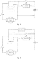
Figure 1 shows the structure diagram of the emergency starting device of the invention and its connection to the engine starting system in the first preferred embodiment. -
Figure 2 shows the structure diagram of the emergency starting device of the invention and its connection to the engine starting system in the second preferred embodiment. -
Figure 3 shows the structure diagram of the emergency starting device of the invention and its connection to the engine starting system in the third preferred embodiment. -
Figure 4 is the circuit diagram of the controller in the emergency starting device of the invention shown inFigure 3 . -
Figure 5 is the circuit diagram of the second relay in the emergency starting device of the invention shown inFigure 3 . - The starting system in the following embodiments of the invention is a starting system for gasoline engine, whose starting voltage is generally of 12V and the output voltage of the accumulator battery in it should be of 13-15V. When the output voltage of the accumulator battery cannot meet the requirement due to the weather or the shortage of energy (or power) caused by energy loss, i.e. in emergency circumstances, the emergency starting device of the invention can be connected to the starting system and substitute the starting system, which is not able to start the engine normally, to start the engine.
- As shown in
Figure 1 , in a first preferred embodiment of the invention, the emergency starting device of the invention has a first output end and a second output end, which are connected to the positive electrode and the negative electrode of the accumulator battery in the starting system respectively. The negative electrode of the accumulator battery is grounded. - The emergency starting device of the invention includes a super-capacitor C1, a controller and a relay K1. The super-capacitor is capable of storing energy (or power) and the energy stored in the super-capacitor C1 in this embodiment can start the engine in emergency. Specifically, one end (i.e. one plate) of the super-capacitor C1 is connected to the positive electrode of the accumulator battery via the relay K1, the other end (i.e. the other plate) is grounded. In practice, the super-capacitor C1 is multiple commercially available super-capacitors connected in series because the voltage of an individual super-capacitor is generally 2.5-2.7V while a voltage of 13V-15V is needed to start an engine whose starting voltage is 12V and a voltage of 26-28V is needed to start an engine whose starting voltage is 24V. The relay K1 is a normally open relay.
- One output end of the controller is connected to the relay K1 to output a control signal S1 to control the on and off of the relay K1. One input end of the controller is connected to the positive electrode of the accumulator battery to receive the electrical signal form the accumulator battery in real time, for example to receive the
signal 100 times per second. The signal can be a voltage V1 (as shown inFigure 1 ), and can be a current as well. When the starting system ignites, that is when the switch K0 shown inFigure 1 is closed, the output voltage and the current at the electrodes of the accumulator battery will undergo a sudden change. Thus the ignition of the starting system can be detected by receiving the signal. When the controller detects the ignition of the starting system, it sends out the control signal S1 to close the relay K1 to electrically connect the super-capacitor C1 and the accumulator battery, thereby the energy (or power) in the super-capacitor C1 can be outputted to start the engine. - In this embodiment, the controller receives the voltage V1 at the positive electrode of the accumulator battery and sends out the control signal S1 to close the relay K1 to electrically connect the super-capacitor C1 and the accumulator battery when it detects a sudden decrease of the voltage V1, for example the decreasing rate is not less than 2V/s. In other embodiments, the controller can receive the current at the positive electrode of the accumulator battery by arranging a Hall element to the starting cable of the automobile, for example. The detected current at the cable is the current received at the positive electrode of the accumulator battery. The controller sends out the control signal S1 to close the relay K1 to electrically connect the super-capacitor C1 and the accumulator battery when it detects a sudden increase of the current, for example with an increasing rate of no less than 20A/s.
- In addition, another input end of the controller is connected to the non-grounded end of the super-capacitor C1 to receive the electrical signal from the super-capacitor C1 in real time, specifically to receive the voltage V2 at the non-grounded end of the super-capacitor, for example to receive the
signal 100 times per second. The controller can calculate the energy (or power) stored in the super-capacitor C1 and determine whether the energy (or power) is sufficient to start the engine. Specifically, the starting current for a small car is about 200A and with a duration time of 2 seconds. The energy needed for one starting can be calculated by the following equation:
- In the above equation, V1 is the end voltage of the accumulator battery with a unit of volt, A is the starting current of the engine with a unit of ampere, T is the duration time for one starting with a unit of hour, E1 is the energy with a unit of watt·hour. The equation to calculate the energy stored in the super-capacitor is:

- In the above equation, C is the capacitance of the super-capacitor C1 with a unit of Farad, V is the end voltage V2 of the super-capacitor C1 with a unit of volt, E is the energy with a unit of watt·hour.
- For example, the stored energy calculated by the controller for the super-capacitor of 150F with V2=2.5V is:

- The total energy stored in the super-capacitor C1 formed by N super-capacitors connected in series is N·E, so the controller can determine whether the energy stored in the super-capacitor C1 is sufficient to start the engine by comparing the total energy of the super-capacitor C1 to the energy E1 needed to start the engine once. Preferably, the total energy of the super-capacitor C1 should not be less than twice of the E1.
- The controller determines that the energy (or power) of the super-capacitor C1 is not sufficient to start the engine and sends out an indicating signal when it determines that the total energy of the super-capacitor C1 is less than the energy E1 needed to start the engine once. The indicating signal can be an alarm sent out by a speaker controlled by the controller, light emitted by LED or picture and/or words presented on a screen, to indicate the user that the energy (or power) in the super-capacitor is insufficient and the super-capacitor needs to be charged.
- The controller in the embodiment includes chips, whose circuit is the same with the circuit of the controller shown in
Figure 4 , except that the output ends K2_CON and K3_CON for outputting the control signals S2 and S3 are not needed. The detail will be discussed later. - Preferably, the controller is set to receive the voltage V2 immediately after the first output end and the second output end of the emergency starting device of the invention are connected to the positive electrode and the negative electrode of the accumulator battery in the starting system, to detect the energy of the super-capacitor C1.
- In addition, the controller can be equipped with a switch, which generally is a button. When the switch is on, the controller functions and can receive signals, process signals and output signals. When the switch is off, the controller does not function. After the first output end and the second output end of the emergency starting device of the invention are connected to the positive electrode and the negative electrode of the accumulator battery in the starting system, the user turns on the switch of the controller, the controller will receive the voltage V2 in real time immediately to detect the energy in the super-capacitor C1.
- Accordingly, the emergency starting method of the invention in the embodiment includes the following steps:
- 1. using the super-capacitor C1, which has energy stored in it;
- 2. using the controller, which receives the electrical signal from the accumulator battery in the starting system in real time and sends out the control signal S1 to the relay K1 to close the relay K1 when the electrical signal changes suddenly, to electrically connect the super-capacitor C1 and the accumulator battery to start the engine with the energy stored in the super-capacitor C1.
- Wherein, the negative electrode of the accumulator battery is grounded, one end of the super-capacitor C1 is connected to the positive electrode of the accumulator battery via the relay K1, and the other end of the super-capacitor C1 is grounded. The electrical signal from the accumulator battery is the voltage V1 at its positive electrode. The controller receives the voltage V1 at a frequency of 100 times per second.
- Further, the controller receives the electrical signal from the super-capacitor C1 in real time, which is the voltage V2 at the non-grounded end of the super-capacitor C1 specifically. The controller receives the voltage V2 at a frequency of 100 times per second. The controller calculates the energy stored in the super-capacitor C1 according to the voltage V2 and determines whether the energy is sufficient to start the engine. If the result is that the energy is sufficient to start the engine, the controller sends out the control signal S1 to the relay K1 when the electrical signal from the accumulator battery changed suddenly. If the result is that the energy is insufficient to start the engine, the controller sends out the indicating signal to indicate the user that the energy in the super-capacitor is insufficient and the super-capacitor needs to be charged.
- As shown in
Figure 2 , in the second preferred embodiment of the invention, the emergency starting device of the invention has a first output end and a second output end, which are connected to the positive electrode and the negative electrode of the accumulator battery in the starting system respectively. The negative electrode of the accumulator battery is grounded. - The emergency starting device of the invention includes a super-capacitor C1, a controller, a relay K1 and a DC-DC booster circuit. Specifically, one end (i.e. one plate) of the super-capacitor C1 is connected to the positive electrode of the accumulator battery via the relay K1, the other end (i.e. the other plate) is grounded. The DC-DC booster circuit is connected to the relay K1 in parallel. Similarly in practice, the super-capacitor C1 is multiple commercially available super-capacitors connected in series. The relay K1 is a normally open relay.
- The super-capacitor C1 in this embodiment is not required to have energy stored in it but can have energy charged into it with the remaining energy in the accumulator battery by the DC-DC booster circuit. When the engine cannot be started, the accumulator battery still has a voltage of 8-12V though it cannot perform high current discharging, thus it is possible to transfer the energy (or power) remained in the accumulator battery to the super-capacitor C1 by the DC-DC booster circuit. Preferably, the input current to the DC-DC booster circuit should be less than 20A so the end voltage of the accumulator battery will not drop drastically.
- One output end of the controller is connected to the relay K1 to output a control signal S1 to control the on and off of the relay K1. One input end of the controller is connected to the positive electrode of the accumulator battery to receive the electrical signal form the accumulator battery in real time. Same as the first embodiment, the electrical signal can be the voltage V1 (as shown in
Figure 2 ), and can be a current as well. The controller receives the voltage V1 at a frequency of 100 times per second. In addition, another input end of the controller is connected to one end of the super-capacitor C1, specifically to the non-grounded end of the super-capacitor C1, to receive the electrical signal from the super-capacitor C1 in real time, specifically to receive the voltage V2 at the non-grounded end of the super-capacitor C1. The controller receives the voltage V2 at a frequency of 100 times per second. The controller can calculate the energy (or power) stored in the super-capacitor C1 according to the voltage V2, and determine whether the energy (or power) is sufficient to start the engine. - When the starting system ignites, that is when the switch K0 shown in
Figure 2 is closed, the voltage and the current outputted at the electrodes of the accumulator battery will change suddenly. So the ignition of the starting system can be detected by receiving the electrical signal. The detection is the same as that described in the first embodiment, and will not be described here. When the controller detects the ignition of the starting system and determines that the energy (or power) in the super-capacitor C1 is sufficient to start the engine, it sends out the control signal S1 to close the relay K1 to electrically connect the super-capacitor C1 and the accumulator battery, thereby the energy (or power) in the super-capacitor C1 can be outputted to start the engine. - Since the energy (or power) remained in the accumulator battery is limited, it is possible that the energy in the super-capacitor which has been charged by the accumulator battery is still insufficient to start the engine. Under this circumstance, the controller will send out an indicating signal when it determines that the energy stored in the super-capacitor C1 is insufficient to start the engine after a preset time interval's detection, for example 5 minutes' detection. The indicating signal can be an alarm sent out by a speaker controlled by the controller, light emitted by LED or picture and/or words presented on a screen, to indicate the user that the energy (or power) in the super-capacitor is insufficient and the super-capacitor needs to be charged by an outer charger.
- The controller in the embodiment has a same circuit as that of the previous embodiment, and will not be described here.
- Preferably, the controller is set to receive the voltage V2 immediately after the first output end and the second output end of the emergency starting device of the invention are connected to the positive electrode and the negative electrode of the accumulator battery in the starting system, to detect the energy of the super-capacitor C1.
- In addition, the controller can be equipped with a switch, which generally is a button. When the switch is on, the controller functions and can receive signals, process signals and output signals. When the switch is off, the controller does not function. After the first output end and the second output end of the emergency starting device of the invention are connected to the positive electrode and the negative electrode of the accumulator battery in the starting system, the user turns on the switch of the controller, the controller will receive the voltage V2 in real time immediately to detect the energy in the
super-capacitor C 1. - Accordingly, the emergency starting method of the invention in the embodiment includes the following steps:
- 1. using the super-capacitor C1, which is connected to the accumulator battery via the DC-DC booster circuit; the super-capacitor C1 is charged with the output voltage of the accumulator battery increased by the DC-DC booster circuit.
- 2. using the controller, which receives the electrical signal from the accumulator battery in the starting system in real time and sends out the control signal S1 to the relay K1 to close the relay K1 when the electrical signal changes suddenly, so as to electrically connects the super-capacitor C1 and the accumulator battery to start the engine with the energy stored in the super-capacitor C1.
- Wherein, the negative electrode of the accumulator battery is grounded, one end of the super-capacitor C1 is connected to the positive electrode of the accumulator battery via the relay K1, and the other end of the super-capacitor C1 is grounded. The electrical signal from the accumulator battery is the voltage V1 at the positive electrode thereof. The controller receives the voltage V1 at a frequency of 100 times per second.
- Further, the controller receives the electrical signal from the super-capacitor C1 in real time, which is the voltage V2 at the non-grounded end of the super-capacitor C1 specifically. The controller receives the voltage V2 at a frequency of 100 times per second. The controller calculates the energy stored in the super-capacitor C1 according to the voltage V2 and determines whether the energy is sufficient to start the engine. If the result is that the energy is sufficient to start the engine, the controller sends out the control signal S1 to the relay K1 when the electrical signal from the accumulator battery changes suddenly. If the result is that the energy is not enough to start the engine after a preset time interval's detection, for example 5 minutes' detection, the controller sends out the indicating signal to indicate the user that the energy in the super-capacitor is insufficient and the super-capacitor needs to be charged by an outer charger.
- As shown in
Figure 3 , in the third preferred embodiment of the invention, the emergency starting device of the invention has a first output end and a second output end, which are connected to the positive electrode and the negative electrode of the accumulator battery in the starting system respectively. The negative electrode of the accumulator battery is grounded. - The emergency starting device of the invention includes a super-capacitor C1, a controller, a first relay K1, a second relay K2, a third relay K3, a DC-DC booster circuit and a battery pack. Specifically, one end (i.e. one plate) of the super-capacitor C1 is connected to the positive electrode of the accumulator battery via the relay K1, the other end (i.e. the other plate) is grounded. The positive electrode of the battery pack is connected to the non-grounded end of the super-capacitor C1 via the third relay K3 and the DC-DC booster circuit, and its negative electrode is grounded. The DC-DC booster circuit is connected to the second relay K2 in series, and the series-connected DC-DC booster circuit and second relay K2 are connected to the first relay K1 in parallel. Similarly in practice, the super-capacitor C1 is multiple commercially available super-capacitors connected in series. The first relay K1, the second relay K2 and the third relay K3 are normally open relays. Preferably, the battery pack is a rechargeable battery pack, such as lead-acid battery pack, NI-MH battery pack, lithium battery pack and etc. More preferably, it is an 18650 lithium battery pack. The super-capacitor C1 in this embodiment is not required to have energy stored in it but can be charged by the battery pack. Since in the embodiment the battery pack is connected to the super-capacitor C1 via the third relay K3 and the DC-DC booster circuit, and the DC-DC booster circuit can increase the output voltage of the battery pack to charge the super-capacitor C1 when the third relay K3 is closed, the output voltage of the battery pack can be lower than the starting voltage. For example, the battery pack can be multiple 18650 lithium battery connected in parallel.
- One output end of the controller is connected to the relay K1 to output a control signal S1 to control the on and off of the first relay K1, another output end of the controller is connected to the second relay K2 to output a control signal S2 to control the on and off of the second relay K2, and the third output end of the controller is connected to the third relay K3 to output a control signal S3 to control the on and off of the third relay K3. One input end of the controller is connected to the positive electrode of the accumulator battery to receive the first electrical signal from the accumulator battery in real time. Same as the first embodiment, the electrical signal can be the voltage V1 (as shown in
Figure 3 ), and can be a current as well. The controller receives the voltage V1 at a frequency of 100 times per second. In addition, another input end of the controller is connected to one end of the super-capacitor C1, specifically to the non-grounded end of the super-capacitor C1 to receive the second electrical signal from the super-capacitor C1 in real time, specifically to receive the voltage V2 at the non-grounded end of the super-capacitor C1. The controller receives the voltage V2 at a frequency of 100 times per second. The controller can calculate the energy (or power) stored in the super-capacitor C1 according to the voltage V2, and determine whether the energy (or power) is sufficient to start the engine. - When the starting system ignites, that is when the switch K0 shown in
Figure 3 is closed, the voltage and the current outputted at the electrodes of the accumulator battery will change suddenly. So the ignition of the starting system can be detected by receiving the electrical signal. The detection is the same as that described in the first embodiment, and will not be described here. - When the controller detects the ignition of the starting system and determines that the energy (or power) in the super-capacitor C1 is sufficient to start the engine according to the voltage V2, it sends out the control signal S1 to close the first relay K1 to electrically connect the super-capacitor C1 and the accumulator battery, thereby the energy in the super-capacitor C1 can be outputted to start the engine. When the controller detects the ignition of the starting system and determines that the energy in the super-capacitor C1 is insufficient to start the engine according to the voltage V2 and the third relay K3 is open, it sends out the control signal S3 to close the third relay K3 to electrically connect the super-capacitor C1 and the battery pack via the DC-DC booster circuit, thereby the battery pack charges the super-capacitor C1. The controller keeps on calculating the energy in the super-capacitor C1 according to the voltage V2 in real time, and when it determines that the energy in the super-capacitor C1 is sufficient to start the engine, it sends out the control signal S1 to close the first relay K1 and stops sending out the control signal S3 to open the third relay K3 so as to electrically connect the super-capacitor C1 and the accumulator battery, thereby the energy in the super-capacitor C1 can be outputted to start the engine. If the controller determines that the energy stored in the super-capacitor C1 is still insufficient to start the engine after a preset time interval's detection, for example 5 minutes' detection since the third relay K3 is closed, and the second relay K2 is open, it sends out the control signal S2 to close the second relay K2 and stops sending out the control signal S3 to open the third relay K3 to electrically connect the super-capacitor C1 and the accumulator battery via the DC-DC booster circuit, thus the accumulator battery charges the super-capacitor C1. The controller keeps on calculating the energy in the super-capacitor C1 according to the voltage V2 in real time, and when it determines that the energy in the super-capacitor C1 is sufficient to start the engine, it sends out the control signal S1 to close the first relay K1 and stops sending out the control signal S2 to open the second relay K2 to electrically connect the super-capacitor C1 and the accumulator battery, thereby the energy in the super-capacitor C1 can be outputted to start the engine. If the controller determines that the energy stored in the super-capacitor C1 is still insufficient to start the engine after a preset time interval's detection, for example 5 minutes' detection since the second relay K2 is closed, it sends out an indicating signal to indicate the user that the energy in the super-capacitor is insufficient and the battery pack should be replaced or the super-capacitor and/or the battery pack should be charged by an outer charger.
- The circuit of the controller in the embodiment is shown as
Figure 4 . The controller includes a chip U3, a chip VR1, a chip U2 and several resistors, capacitors, diodes and a inductance, wherein the chip U3 is MA86E/L508, the chip VR1 is 78L05, the chip U2 is AX5201, the resistance values of the resistors R13, R14 and R22 are shown in the figure, the capacitance values of the capacitors C8, C9, C10, C15, C16 and C20 are shown in the figure, the inductance value of the inductance L3 is shown in the figure, the types of the diodes D5, D6 and D7 are shown in the figure, and the connection between all these elements are as shown in the figure. The two input ends of the controller receive the first electrical signal and the second electrical signal, i.e. voltage V1 and voltage V2, respectively. Its three output ends are the three output ports K1_CON, K2_CON and K3_CON of the chip U3, and are used for outputting control signals S1, S2 and S3. - The control signals S1, S2 and S3 are used for control the on and off of the first, the second and the third relays K1, K2 and K3. Specifically, the first, the second and the third relays K1, K2 and K3 are normally open relays. They will close when the control signals S1, S2 and S3 are loaded, and open when the control signals S1, S2 and S3 are unloaded. The circuit of the first, the second and the third relays K1, K2 and K3 in the embodiment are same, and will be described below taking the second relay K2 as the example.
- Referring to
Figure 5 , the two ends, a and b, of the second relay K2 are connected to the positive electrode and the negative electrode of the accumulator battery respectively. The second relay K2 is connected to the resistor R12, the transistor Q3 and the diode D4 in the way as shown in the figure. The resistor R12 is connected to the port K2_CON of the chip U3 of the controller to receive the control signal S2 from the controller. The types and values of the elements are shown in the figure and will be not described here. - Preferably, the controller is set to receive the voltage V2 when the first output end and the second output end of the emergency starting device of the invention are connected to the positive electrode and the negative electrode of the accumulator battery in the starting system, to detect the energy of the super-capacitor C1.
- In addition, the controller can be equipped with a switch, which generally is a button. When the switch is on, the controller functions and can receive signals, process signals and output signals. When the switch is off, the controller does not function. After the first output end and the second output end of the emergency starting device of the invention are connected to the positive electrode and the negative electrode of the accumulator battery in the starting system, the user turns on the switch of the controller, the controller will immediately receive the voltage V2 in real time to detect the energy in the
super-capacitor C 1. - Accordingly, the emergency starting method of the invention in the embodiment includes the following steps:
- 1. using the super-capacitor C1, the battery pack and the DC-DC booster circuit, wherein the super-capacitor C1 is connected to the battery pack via the third relay K3 and the DC-DC booster circuit; the super-capacitor C1 is connected to the accumulator battery via the second relay K2 and DC-DC booster circuit; the DC-DC booster circuit is used for increasing the output voltage of the battery pack or the accumulator battery to charge the super-capacitor C1;
- 2. using the controller, which receives the first electrical signal from the accumulator battery in the starting system and the second electrical signal from the super-capacitor C1 in real time, and calculates the energy (or power) stored in the super-capacitor C1 according to the second electrical signal and determines whether the energy (or power) is sufficient to start the engine. When the controller detects the sudden change of the first electrical signal and determines that the energy in the super-capacitor C1 is sufficient to start the engine, the controller sends out the control signal S1 to close the first relay K1 to electrically connect the super-capacitor C1 and the accumulator battery, thus the energy in the super-capacitor C1 can be outputted to start the engine. When the controller detects the sudden change of the first electrical signal and determines that the energy in the super-capacitor C1 is insufficient to start the engine, it sends out the control signal S3 to close the third relay K3 to electrically connect the super-capacitor C1 and the battery pack via the DC-DC booster circuit, thus the battery pack charges the super-capacitor C1. The controller keeps on calculating the energy in the super-capacitor C1 according to the second electrical signal in real time, and when it determines that the energy in the super-capacitor C1 is sufficient to start the engine, it sends out the control signal S1 to close the first relay K1 and stops sending out the control signal S3 to open the third relay K3, thus the energy in the super-capacitor C1 can be outputted to start the engine. If the controller determines that the energy stored in the super-capacitor C1 is still insufficient to start the engine after a preset time interval's detection, for example 5 minutes' detection since the third relay K3 is closed, and the second relay K2 is open, it sends out the control signal S2 to close the second relay K2 and stops sending out the control signal S3 to open the third relay K3 to electrically connect the super-capacitor C1 and the accumulator battery via the DC-DC booster circuit, thus the accumulator battery charges the super-capacitor C1. The controller keeps on calculating the energy in the super-capacitor C1 according to the voltage V2 in real time, and when it determines that the energy in the super-capacitor C1 is sufficient to start the engine, it sends out the control signal S1 to close the first relay K1 and stops sending out the control signal S2 to open the second relay K2, thus the energy in the super-capacitor C1 can be outputted to start the engine. If the controller determines that the energy stored in the super-capacitor C1 is still insufficient to start the engine after a preset time interval's detection, for example 5 minutes' detection since the second relay K2 is closed, it sends out an indicating signal to indicate the user that the energy in the super-capacitor is insufficient and the battery pack should be replaced or the super-capacitor and/or the battery pack should be charged by an outer charger.
- Wherein the negative electrode of the accumulator battery is grounded, one end of the super-capacitor C1 is connected to the positive electrode of the accumulator battery via the first relay K1, and the other end of the super-capacitor C1 is grounded. The positive electrode of the battery pack is connected to the non-grounded end of the super-capacitor C1 via the third relay K3 and the DC-DC booster circuit, and its negative electrode is grounded. The series-connected second relay K2 and DC-DC booster are connected between the positive electrode of the accumulator battery and the non-grounded end of the super-capacitor C1. The first electrical signal is the voltage V1 at the positive electrode of the accumulator battery, and the second electrical signal is the voltage V2 at the non-grounded end of the super-capacitor C1. The controller receives the voltage V1 at a frequency of 100 times per second, and receives the voltage V2 at a frequency of 100 times per second.
- The preferred embodiments of the invention have been described above in detail. It is to be understood that those skilled in the art may make changes or modifications based on the inventive concepts of the invention without any creative work. Accordingly, any technical solution that those skilled in the art conceived by way of logic analysis, reasoning or finite experiments, should be considered to be in the extent of protection as defined by the claims.
Claims (10)
- An emergency starting device, for use when an engine starting system cannot start an engine, including a first output end and a second output end, wherein the first output end is, in use, connected to a positive electrode of an accumulator battery in the engine starting system and the second output end is, in use, connected to a negative electrode of the accumulator battery, wherein the device includes a super-capacitor, a controller and a DC-DC booster circuit, whereinthe DC-DC booster circuit is arranged, in use, to be connected between the super-capacitor and the accumulator battery,the DC-DC booster circuit is arranged to increase the output voltage of the accumulator battery to charge the super-capacitor;the negative electrode of the accumulator battery is grounded;the controller is arranged to receive a first electrical signal from the accumulator battery, the first electrical signal being a voltage at the positive electrode of the accumulator battery; characterised in that:the controller is arranged to electrically connect the super-capacitor and the accumulator battery to start the engine with energy stored in the super-capacitor when the voltage decreases at a rate of no less than 2V/s.
- An emergency starting device, for use when an engine starting system cannot start an engine, including a first output end and a second output end, wherein the first output end is, in use, connected to a positive electrode of an accumulator battery in the engine starting system and the second output end is, in use, connected to a negative electrode of the accumulator battery, wherein the device includes a super-capacitor, a controller and a DC-DC booster circuit, whereinthe DC-DC booster circuit is arranged, in use, to be connected between the super-capacitor and the accumulator battery,the DC-DC booster circuit is arranged to increase the output voltage of the accumulator battery to charge the super-capacitor;the negative electrode of the accumulator battery is grounded;the controller is arranged to receive a first electrical signal from the accumulator battery, characterized in that the first electrical signal is a current at the positive electrode of the accumulator battery; andthe controller is arranged to electrically connect the super-capacitor and the accumulator battery to start the engine with energy stored in the super-capacitor when the current increases at a rate of no less than 20A/s.
- The emergency starting device according to Claim 1 or Claim 2, wherein the emergency starting device further includes a normally open relay, via which one end of the super-capacitor is connected to the positive electrode of the accumulator battery, and the other end of the super-capacitor is grounded; the controller closes the relay to electrically connect the super-capacitor and the accumulator battery when the first electrical signal changes suddenly.
- The emergency starting device according to Claim 3, wherein the controller further receives a second electrical signal from the super-capacitor and calculates the energy stored in the super-capacitor according to the electrical signal from the super-capacitor; the controller sends out an indicating signal when the energy is insufficient to start the engine.
- The emergency starting device according to Claim 4, wherein the second electrical signal is a voltage at a non-grounded end of the super-capacitor.
- The emergency starting device according to any of Claim 1 or Claim 2, wherein the controller is equipped with a switch; the controller functions when the switch is on, the controller does not function when the switch is off.
- An emergency starting method used when a starting system cannot start an engine, including the following steps:using a super-capacitor, a DC-DC booster circuit is connected between the super-capacitor and an accumulator battery in the starting system to increase an output voltage of the accumulator battery to charge the super-capacitor, and a negative electrode of the accumulator battery is grounded;using a controller, which receives a first electrical signal from the accumulator battery, characterized in that:(i) the first electrical signal is a voltage at the positive electrode of the accumulator battery; and the controller electrically connects the super-capacitor and the accumulator battery to start the engine with energy stored in the super-capacitor when the voltage decreases at a rate of no less than 2V/s; or(ii) the first electrical signal is a current at the positive electrode of the accumulator battery; and the controller electrically connects the super-capacitor and the accumulator battery to start the engine with energy stored in the super-capacitor when the current increases at a rate of no less than 20A/s.
- The emergency starting method according to Claim 7, wherein the controller further receives a second electrical signal from the super-capacitor and calculates the energy stored in the super-capacitor according to the second electrical signal; the controller electrically connects the super-capacitor to the accumulator battery via the DC-DC booster circuit when the energy is insufficient to start the engine, to have the super-capacitor charged by the output voltage of the accumulator battery increased by the DC-DC booster circuit.
- The emergency starting method according to Claim 8, wherein the second electrical signal is a voltage at a non-grounded end of the super-capacitor.
- The emergency starting method according to Claim 9, wherein the controller is equipped with a switch; the controller functions when the switch is on, the controller does not function when the switch is off.
Applications Claiming Priority (1)
| Application Number | Priority Date | Filing Date | Title |
|---|---|---|---|
| CN201510169078 | 2015-04-10 |
Publications (2)
| Publication Number | Publication Date |
|---|---|
| EP3079221A1 EP3079221A1 (en) | 2016-10-12 |
| EP3079221B1 true EP3079221B1 (en) | 2017-11-22 |
Family
ID=53719599
Family Applications (1)
| Application Number | Title | Priority Date | Filing Date |
|---|---|---|---|
| EP15167725.9A Active EP3079221B1 (en) | 2015-04-10 | 2015-05-14 | Emergency starting device and emergency starting method |
Country Status (6)
| Country | Link |
|---|---|
| US (1) | US10174736B2 (en) |
| EP (1) | EP3079221B1 (en) |
| JP (1) | JP2018517095A (en) |
| CN (1) | CN207283184U (en) |
| AU (1) | AU2015390343A1 (en) |
| WO (1) | WO2016161687A1 (en) |
Families Citing this family (31)
| Publication number | Priority date | Publication date | Assignee | Title |
|---|---|---|---|---|
| WO2018000130A1 (en) * | 2016-06-27 | 2018-01-04 | 张磊 | Engine standby power supply apparatus |
| IT201700050571A1 (en) * | 2017-05-10 | 2018-11-10 | Beta Utensili Spa | Portable starter |
| US10819132B2 (en) | 2017-08-04 | 2020-10-27 | Deltran Operations Usa, Inc. | Device with battery charger system and engine start system formed from high frequency transformers |
| JP6732831B2 (en) * | 2018-04-10 | 2020-07-29 | 矢崎総業株式会社 | Power supply |
| CN110739755A (en) * | 2018-07-02 | 2020-01-31 | 深圳市格威特光电科技有限公司 | super capacitor control module and control method |
| GB2576699A (en) * | 2018-08-09 | 2020-03-04 | Zapgo Ltd | Charging a capacitor from a battery |
| US11245280B2 (en) | 2018-08-21 | 2022-02-08 | Milwaukee Electric Tool Corporation | Vehicle battery jump starter powered by a removable and rechargeable battery pack |
| CN109552084A (en) * | 2018-12-30 | 2019-04-02 | 宁波中车新能源科技有限公司 | A kind of hybrid power electric car start stop system and its control method |
| CN109995103A (en) * | 2019-03-11 | 2019-07-09 | 深圳市华思旭科技有限公司 | Emergency starting power supply and emergency starting method |
| US11901729B2 (en) | 2019-03-11 | 2024-02-13 | Shenzhen Carku Technology Co., Limited | Charging device and emergency start method |
| US11432123B2 (en) | 2019-06-07 | 2022-08-30 | Anthony Macaluso | Systems and methods for managing a vehicle's energy via a wireless network |
| US11837411B2 (en) * | 2021-03-22 | 2023-12-05 | Anthony Macaluso | Hypercapacitor switch for controlling energy flow between energy storage devices |
| US11615923B2 (en) | 2019-06-07 | 2023-03-28 | Anthony Macaluso | Methods, systems and apparatus for powering a vehicle |
| US11641572B2 (en) * | 2019-06-07 | 2023-05-02 | Anthony Macaluso | Systems and methods for managing a vehicle's energy via a wireless network |
| US11685276B2 (en) | 2019-06-07 | 2023-06-27 | Anthony Macaluso | Methods and apparatus for powering a vehicle |
| US11289974B2 (en) | 2019-06-07 | 2022-03-29 | Anthony Macaluso | Power generation from vehicle wheel rotation |
| CN110126693A (en) * | 2019-06-24 | 2019-08-16 | 长春市夸克普精汽车电子有限责任公司 | A kind of chair heating device and seat |
| US11591996B2 (en) * | 2020-01-17 | 2023-02-28 | Martin Koebler | Emergency start |
| US11598306B2 (en) * | 2020-01-17 | 2023-03-07 | Martin Koebler | Emergency start |
| CN115461536B (en) | 2020-05-07 | 2023-05-23 | 米沃奇电动工具公司 | Vehicle battery jump starter with multiple battery pack compatibility |
| CN112072740B (en) * | 2020-09-03 | 2023-05-02 | 安徽鸿创新能源动力有限公司 | Under-voltage starting circuit of low-voltage storage battery of electric automobile and control method thereof |
| CN112467821A (en) * | 2020-10-15 | 2021-03-09 | 上海空间电源研究所 | Starting power supply control circuit compatible with UV/2UV output and control method thereof |
| JP2023176047A (en) * | 2020-10-23 | 2023-12-13 | トライポッド・デザイン株式会社 | Power generation element and sensor |
| CN112510810B (en) * | 2020-12-07 | 2023-04-11 | 中国第一汽车股份有限公司 | Automobile and monitoring circuit of power supply system thereof |
| CN115224780A (en) * | 2021-04-19 | 2022-10-21 | 宁波市嘉越机电有限公司 | Automobile emergency starting power supply device and emergency starting method |
| CN113944585A (en) * | 2021-09-18 | 2022-01-18 | 东风柳州汽车有限公司 | Automobile emergency starting device under battery power-lack state and control method |
| CN114320703B (en) * | 2021-11-23 | 2024-02-20 | 深圳供电局有限公司 | Auxiliary ignition device for vehicle and ignition device for vehicle |
| CN114268146B (en) * | 2021-12-07 | 2024-02-13 | 成都长城开发科技股份有限公司 | Power supply device and method for electronic instrument in low-temperature environment |
| US11577606B1 (en) | 2022-03-09 | 2023-02-14 | Anthony Macaluso | Flexible arm generator |
| US11472306B1 (en) | 2022-03-09 | 2022-10-18 | Anthony Macaluso | Electric vehicle charging station |
| US11955875B1 (en) | 2023-02-28 | 2024-04-09 | Anthony Macaluso | Vehicle energy generation system |
Family Cites Families (26)
| Publication number | Priority date | Publication date | Assignee | Title |
|---|---|---|---|---|
| CN2033872U (en) * | 1988-01-16 | 1989-03-08 | 黄琦 | Key type water valve |
| JPH02259277A (en) | 1989-03-31 | 1990-10-22 | Isuzu Motors Ltd | Engine starter device |
| US5793185A (en) * | 1997-06-10 | 1998-08-11 | Deltona Transformer Corporation | Jump starter |
| DE19832874C2 (en) | 1998-07-22 | 2000-10-26 | Daimler Chrysler Ag | Energy supply device for an electromagnetic valve control of an internal combustion engine |
| US6242887B1 (en) * | 2000-08-31 | 2001-06-05 | Kold Ban International, Ltd. | Vehicle with supplemental energy storage system for engine cranking |
| US6426606B1 (en) * | 2000-10-10 | 2002-07-30 | Purkey Electrical Consulting | Apparatus for providing supplemental power to an electrical system and related methods |
| JP2002195139A (en) | 2000-12-26 | 2002-07-10 | Nippon Avionics Co Ltd | Engine starting device |
| US7015674B2 (en) * | 2001-06-22 | 2006-03-21 | Midtronics, Inc. | Booster pack with storage capacitor |
| JP2004072874A (en) * | 2002-08-05 | 2004-03-04 | Fuji Heavy Ind Ltd | Power generation controller for alternator |
| US6803743B2 (en) * | 2002-10-04 | 2004-10-12 | Delphi Technologies, Inc. | Jump start and reverse battery protection circuit |
| KR100675366B1 (en) * | 2002-12-30 | 2007-01-29 | 주식회사 네스캡 | Electric energy storage device and method of charging and discharging the same |
| US7145259B2 (en) | 2003-11-11 | 2006-12-05 | Remy Inc. | Engine starting motor anti-milling device |
| US7199555B2 (en) * | 2004-05-19 | 2007-04-03 | Chien Hung Taiwan Ltd. | Portable emergency vehicle battery charger with microprocessor |
| JP4806981B2 (en) * | 2005-07-06 | 2011-11-02 | パナソニック株式会社 | Engine start storage battery deterioration determination device and engine start storage battery equipped with the deterioration determination device |
| CN2855817Y (en) | 2006-01-13 | 2007-01-10 | 山东理工大学 | Super electric capacity auxiliary starting device used for vehicle |
| KR100837939B1 (en) | 2006-10-11 | 2008-06-13 | 현대자동차주식회사 | Power system of hybrid fuel cell bus and control method thereof |
| EP2144773A4 (en) | 2007-04-04 | 2013-12-04 | Cooper Technologies Co | Methods and systems for supplying power to a load |
| JP5484192B2 (en) * | 2010-05-20 | 2014-05-07 | 本田技研工業株式会社 | Electric vehicle start control device |
| CN102691607B (en) * | 2012-06-08 | 2014-12-03 | 汤如法 | Auxiliary starting device of vehicle engine |
| MY175571A (en) * | 2012-09-07 | 2020-07-01 | Huang Yung Sheng | Method for jump starting a vehicle |
| US9194357B2 (en) * | 2012-11-19 | 2015-11-24 | Yung-Sheng Huang | Method for jump starting a vehicle |
| CN202978396U (en) * | 2012-12-06 | 2013-06-05 | 辽宁百纳电气有限公司 | Super-capacitor automobile engine starting device |
| CN203381507U (en) | 2013-05-30 | 2014-01-08 | 重庆市星海电子有限公司 | Novel energy storage device for vehicle starting |
| WO2014200697A1 (en) | 2013-06-13 | 2014-12-18 | Unison Industries, Llc | Method to decouple battery from high level cranking currents of diesel engines |
| CN203387214U (en) | 2013-06-17 | 2014-01-08 | 安科智慧城市技术(中国)有限公司 | Automobile emergency starting power supply and automobile power supply device |
| CN103441561A (en) | 2013-08-15 | 2013-12-11 | 重庆长安汽车股份有限公司 | Automobile secondary energy storing device based on super-capacitor and control method |
-
2015
- 2015-05-07 JP JP2018503700A patent/JP2018517095A/en active Pending
- 2015-05-07 AU AU2015390343A patent/AU2015390343A1/en not_active Abandoned
- 2015-05-07 US US14/443,021 patent/US10174736B2/en active Active
- 2015-05-07 WO PCT/CN2015/078477 patent/WO2016161687A1/en active Application Filing
- 2015-05-07 CN CN201590001067.5U patent/CN207283184U/en not_active Expired - Fee Related
- 2015-05-14 EP EP15167725.9A patent/EP3079221B1/en active Active
Non-Patent Citations (1)
| Title |
|---|
| None * |
Also Published As
| Publication number | Publication date |
|---|---|
| CN207283184U (en) | 2018-04-27 |
| US10174736B2 (en) | 2019-01-08 |
| AU2015390343A1 (en) | 2018-01-18 |
| EP3079221A1 (en) | 2016-10-12 |
| JP2018517095A (en) | 2018-06-28 |
| WO2016161687A1 (en) | 2016-10-13 |
| US20170191459A1 (en) | 2017-07-06 |
Similar Documents
| Publication | Publication Date | Title |
|---|---|---|
| EP3079221B1 (en) | Emergency starting device and emergency starting method | |
| CN107521441B (en) | Battery management system for vehicle | |
| CA2931115C (en) | Electrical system enhancer | |
| US7339347B2 (en) | Apparatus and method for reliably supplying electrical energy to an electrical system | |
| US10029572B2 (en) | Power source system for a vehicle | |
| US5146095A (en) | Low discharge capacitor motor starter system | |
| US6057666A (en) | Method and circuit for controlling charging in a dual battery electrical system | |
| CN103531861B (en) | Storage battery and motor vehicle | |
| EP2607178A1 (en) | Power supply for powering an electric load of a vehicle | |
| US20140253045A1 (en) | Method and apparatus for battery control | |
| CN103228905A (en) | Mobile starter device | |
| US9350186B2 (en) | Battery pack | |
| WO2014142759A1 (en) | Battery pack | |
| CN109952236A (en) | The control method and automotive power supply system of automotive power supply system | |
| EP1025632B1 (en) | Method and circuit for controlling charging in a dual battery electrical system | |
| EP3975381A1 (en) | Battery protection apparatus and battery system including the same | |
| US20200139821A1 (en) | Power supply device | |
| EP3454444A1 (en) | Power supply device | |
| US11482820B2 (en) | Charging apparatus | |
| CN209963790U (en) | 24V emergency starting power supply | |
| CN113178934A (en) | Integrated low-voltage energy storage power supply system for vehicle and control method thereof | |
| CN106169801B (en) | Switching device for discharging an energy store of a motor vehicle | |
| KR20160067600A (en) | Apparatus and method for protecting overcharge of battery cell | |
| RU136099U1 (en) | COMBINED START-UP SYSTEM FOR INTERNAL COMBUSTION ENGINE | |
| MXPA00002670A (en) | Battery charge maintenance system and method |
Legal Events
| Date | Code | Title | Description |
|---|---|---|---|
| PUAI | Public reference made under article 153(3) epc to a published international application that has entered the european phase |
Free format text: ORIGINAL CODE: 0009012 |
|
| 17P | Request for examination filed |
Effective date: 20160622 |
|
| AK | Designated contracting states |
Kind code of ref document: A1 Designated state(s): AL AT BE BG CH CY CZ DE DK EE ES FI FR GB GR HR HU IE IS IT LI LT LU LV MC MK MT NL NO PL PT RO RS SE SI SK SM TR |
|
| AX | Request for extension of the european patent |
Extension state: BA ME |
|
| GRAP | Despatch of communication of intention to grant a patent |
Free format text: ORIGINAL CODE: EPIDOSNIGR1 |
|
| INTG | Intention to grant announced |
Effective date: 20170818 |
|
| GRAS | Grant fee paid |
Free format text: ORIGINAL CODE: EPIDOSNIGR3 |
|
| GRAA | (expected) grant |
Free format text: ORIGINAL CODE: 0009210 |
|
| AK | Designated contracting states |
Kind code of ref document: B1 Designated state(s): AL AT BE BG CH CY CZ DE DK EE ES FI FR GB GR HR HU IE IS IT LI LT LU LV MC MK MT NL NO PL PT RO RS SE SI SK SM TR |
|
| REG | Reference to a national code |
Ref country code: GB Ref legal event code: FG4D |
|
| REG | Reference to a national code |
Ref country code: CH Ref legal event code: EP |
|
| REG | Reference to a national code |
Ref country code: IE Ref legal event code: FG4D |
|
| REG | Reference to a national code |
Ref country code: AT Ref legal event code: REF Ref document number: 949244 Country of ref document: AT Kind code of ref document: T Effective date: 20171215 |
|
| REG | Reference to a national code |
Ref country code: DE Ref legal event code: R096 Ref document number: 602015006109 Country of ref document: DE |
|
| REG | Reference to a national code |
Ref country code: NL Ref legal event code: MP Effective date: 20171122 |
|
| REG | Reference to a national code |
Ref country code: LT Ref legal event code: MG4D |
|
| REG | Reference to a national code |
Ref country code: AT Ref legal event code: MK05 Ref document number: 949244 Country of ref document: AT Kind code of ref document: T Effective date: 20171122 |
|
| PG25 | Lapsed in a contracting state [announced via postgrant information from national office to epo] |
Ref country code: ES Free format text: LAPSE BECAUSE OF FAILURE TO SUBMIT A TRANSLATION OF THE DESCRIPTION OR TO PAY THE FEE WITHIN THE PRESCRIBED TIME-LIMIT Effective date: 20171122 Ref country code: FI Free format text: LAPSE BECAUSE OF FAILURE TO SUBMIT A TRANSLATION OF THE DESCRIPTION OR TO PAY THE FEE WITHIN THE PRESCRIBED TIME-LIMIT Effective date: 20171122 Ref country code: NO Free format text: LAPSE BECAUSE OF FAILURE TO SUBMIT A TRANSLATION OF THE DESCRIPTION OR TO PAY THE FEE WITHIN THE PRESCRIBED TIME-LIMIT Effective date: 20180222 Ref country code: NL Free format text: LAPSE BECAUSE OF FAILURE TO SUBMIT A TRANSLATION OF THE DESCRIPTION OR TO PAY THE FEE WITHIN THE PRESCRIBED TIME-LIMIT Effective date: 20171122 Ref country code: SE Free format text: LAPSE BECAUSE OF FAILURE TO SUBMIT A TRANSLATION OF THE DESCRIPTION OR TO PAY THE FEE WITHIN THE PRESCRIBED TIME-LIMIT Effective date: 20171122 Ref country code: LT Free format text: LAPSE BECAUSE OF FAILURE TO SUBMIT A TRANSLATION OF THE DESCRIPTION OR TO PAY THE FEE WITHIN THE PRESCRIBED TIME-LIMIT Effective date: 20171122 |
|
| REG | Reference to a national code |
Ref country code: FR Ref legal event code: PLFP Year of fee payment: 4 |
|
| PG25 | Lapsed in a contracting state [announced via postgrant information from national office to epo] |
Ref country code: BG Free format text: LAPSE BECAUSE OF FAILURE TO SUBMIT A TRANSLATION OF THE DESCRIPTION OR TO PAY THE FEE WITHIN THE PRESCRIBED TIME-LIMIT Effective date: 20180222 Ref country code: GR Free format text: LAPSE BECAUSE OF FAILURE TO SUBMIT A TRANSLATION OF THE DESCRIPTION OR TO PAY THE FEE WITHIN THE PRESCRIBED TIME-LIMIT Effective date: 20180223 Ref country code: RS Free format text: LAPSE BECAUSE OF FAILURE TO SUBMIT A TRANSLATION OF THE DESCRIPTION OR TO PAY THE FEE WITHIN THE PRESCRIBED TIME-LIMIT Effective date: 20171122 Ref country code: HR Free format text: LAPSE BECAUSE OF FAILURE TO SUBMIT A TRANSLATION OF THE DESCRIPTION OR TO PAY THE FEE WITHIN THE PRESCRIBED TIME-LIMIT Effective date: 20171122 Ref country code: AT Free format text: LAPSE BECAUSE OF FAILURE TO SUBMIT A TRANSLATION OF THE DESCRIPTION OR TO PAY THE FEE WITHIN THE PRESCRIBED TIME-LIMIT Effective date: 20171122 Ref country code: LV Free format text: LAPSE BECAUSE OF FAILURE TO SUBMIT A TRANSLATION OF THE DESCRIPTION OR TO PAY THE FEE WITHIN THE PRESCRIBED TIME-LIMIT Effective date: 20171122 |
|
| PG25 | Lapsed in a contracting state [announced via postgrant information from national office to epo] |
Ref country code: EE Free format text: LAPSE BECAUSE OF FAILURE TO SUBMIT A TRANSLATION OF THE DESCRIPTION OR TO PAY THE FEE WITHIN THE PRESCRIBED TIME-LIMIT Effective date: 20171122 Ref country code: CY Free format text: LAPSE BECAUSE OF FAILURE TO SUBMIT A TRANSLATION OF THE DESCRIPTION OR TO PAY THE FEE WITHIN THE PRESCRIBED TIME-LIMIT Effective date: 20171122 Ref country code: DK Free format text: LAPSE BECAUSE OF FAILURE TO SUBMIT A TRANSLATION OF THE DESCRIPTION OR TO PAY THE FEE WITHIN THE PRESCRIBED TIME-LIMIT Effective date: 20171122 Ref country code: SK Free format text: LAPSE BECAUSE OF FAILURE TO SUBMIT A TRANSLATION OF THE DESCRIPTION OR TO PAY THE FEE WITHIN THE PRESCRIBED TIME-LIMIT Effective date: 20171122 Ref country code: CZ Free format text: LAPSE BECAUSE OF FAILURE TO SUBMIT A TRANSLATION OF THE DESCRIPTION OR TO PAY THE FEE WITHIN THE PRESCRIBED TIME-LIMIT Effective date: 20171122 |
|
| REG | Reference to a national code |
Ref country code: DE Ref legal event code: R097 Ref document number: 602015006109 Country of ref document: DE |
|
| PG25 | Lapsed in a contracting state [announced via postgrant information from national office to epo] |
Ref country code: IT Free format text: LAPSE BECAUSE OF FAILURE TO SUBMIT A TRANSLATION OF THE DESCRIPTION OR TO PAY THE FEE WITHIN THE PRESCRIBED TIME-LIMIT Effective date: 20171122 Ref country code: SM Free format text: LAPSE BECAUSE OF FAILURE TO SUBMIT A TRANSLATION OF THE DESCRIPTION OR TO PAY THE FEE WITHIN THE PRESCRIBED TIME-LIMIT Effective date: 20171122 Ref country code: PL Free format text: LAPSE BECAUSE OF FAILURE TO SUBMIT A TRANSLATION OF THE DESCRIPTION OR TO PAY THE FEE WITHIN THE PRESCRIBED TIME-LIMIT Effective date: 20171122 |
|
| PLBE | No opposition filed within time limit |
Free format text: ORIGINAL CODE: 0009261 |
|
| STAA | Information on the status of an ep patent application or granted ep patent |
Free format text: STATUS: NO OPPOSITION FILED WITHIN TIME LIMIT |
|
| 26N | No opposition filed |
Effective date: 20180823 |
|
| PG25 | Lapsed in a contracting state [announced via postgrant information from national office to epo] |
Ref country code: SI Free format text: LAPSE BECAUSE OF FAILURE TO SUBMIT A TRANSLATION OF THE DESCRIPTION OR TO PAY THE FEE WITHIN THE PRESCRIBED TIME-LIMIT Effective date: 20171122 |
|
| REG | Reference to a national code |
Ref country code: CH Ref legal event code: PL |
|
| REG | Reference to a national code |
Ref country code: BE Ref legal event code: MM Effective date: 20180531 |
|
| PG25 | Lapsed in a contracting state [announced via postgrant information from national office to epo] |
Ref country code: MC Free format text: LAPSE BECAUSE OF FAILURE TO SUBMIT A TRANSLATION OF THE DESCRIPTION OR TO PAY THE FEE WITHIN THE PRESCRIBED TIME-LIMIT Effective date: 20171122 |
|
| REG | Reference to a national code |
Ref country code: IE Ref legal event code: MM4A |
|
| PG25 | Lapsed in a contracting state [announced via postgrant information from national office to epo] |
Ref country code: CH Free format text: LAPSE BECAUSE OF NON-PAYMENT OF DUE FEES Effective date: 20180531 Ref country code: LI Free format text: LAPSE BECAUSE OF NON-PAYMENT OF DUE FEES Effective date: 20180531 |
|
| PG25 | Lapsed in a contracting state [announced via postgrant information from national office to epo] |
Ref country code: LU Free format text: LAPSE BECAUSE OF NON-PAYMENT OF DUE FEES Effective date: 20180514 |
|
| PG25 | Lapsed in a contracting state [announced via postgrant information from national office to epo] |
Ref country code: IE Free format text: LAPSE BECAUSE OF NON-PAYMENT OF DUE FEES Effective date: 20180514 |
|
| PG25 | Lapsed in a contracting state [announced via postgrant information from national office to epo] |
Ref country code: BE Free format text: LAPSE BECAUSE OF NON-PAYMENT OF DUE FEES Effective date: 20180531 |
|
| REG | Reference to a national code |
Ref country code: DE Ref legal event code: R082 Ref document number: 602015006109 Country of ref document: DE Representative=s name: DEHMEL & BETTENHAUSEN PATENTANWAELTE PARTMBB, DE Ref country code: DE Ref legal event code: R081 Ref document number: 602015006109 Country of ref document: DE Owner name: NINGBO CARSTEL MANUFACTURING CO., LTD., CN Free format text: FORMER OWNER: ZHANG, LEI, NINGBO CITY, ZHEJIANG, CN |
|
| REG | Reference to a national code |
Ref country code: GB Ref legal event code: 732E Free format text: REGISTERED BETWEEN 20190926 AND 20191002 |
|
| PG25 | Lapsed in a contracting state [announced via postgrant information from national office to epo] |
Ref country code: MT Free format text: LAPSE BECAUSE OF NON-PAYMENT OF DUE FEES Effective date: 20180514 |
|
| PG25 | Lapsed in a contracting state [announced via postgrant information from national office to epo] |
Ref country code: TR Free format text: LAPSE BECAUSE OF FAILURE TO SUBMIT A TRANSLATION OF THE DESCRIPTION OR TO PAY THE FEE WITHIN THE PRESCRIBED TIME-LIMIT Effective date: 20171122 |
|
| PG25 | Lapsed in a contracting state [announced via postgrant information from national office to epo] |
Ref country code: PT Free format text: LAPSE BECAUSE OF FAILURE TO SUBMIT A TRANSLATION OF THE DESCRIPTION OR TO PAY THE FEE WITHIN THE PRESCRIBED TIME-LIMIT Effective date: 20171122 |
|
| PG25 | Lapsed in a contracting state [announced via postgrant information from national office to epo] |
Ref country code: MK Free format text: LAPSE BECAUSE OF NON-PAYMENT OF DUE FEES Effective date: 20171122 Ref country code: RO Free format text: LAPSE BECAUSE OF FAILURE TO SUBMIT A TRANSLATION OF THE DESCRIPTION OR TO PAY THE FEE WITHIN THE PRESCRIBED TIME-LIMIT Effective date: 20171122 Ref country code: HU Free format text: LAPSE BECAUSE OF FAILURE TO SUBMIT A TRANSLATION OF THE DESCRIPTION OR TO PAY THE FEE WITHIN THE PRESCRIBED TIME-LIMIT; INVALID AB INITIO Effective date: 20150514 |
|
| PG25 | Lapsed in a contracting state [announced via postgrant information from national office to epo] |
Ref country code: AL Free format text: LAPSE BECAUSE OF FAILURE TO SUBMIT A TRANSLATION OF THE DESCRIPTION OR TO PAY THE FEE WITHIN THE PRESCRIBED TIME-LIMIT Effective date: 20171122 Ref country code: IS Free format text: LAPSE BECAUSE OF FAILURE TO SUBMIT A TRANSLATION OF THE DESCRIPTION OR TO PAY THE FEE WITHIN THE PRESCRIBED TIME-LIMIT Effective date: 20180322 |
|
| PGFP | Annual fee paid to national office [announced via postgrant information from national office to epo] |
Ref country code: FR Payment date: 20230523 Year of fee payment: 9 Ref country code: DE Payment date: 20230510 Year of fee payment: 9 |
|
| PGFP | Annual fee paid to national office [announced via postgrant information from national office to epo] |
Ref country code: GB Payment date: 20230519 Year of fee payment: 9 |