EP3079184A1 - Onboard battery - Google Patents
Onboard battery Download PDFInfo
- Publication number
- EP3079184A1 EP3079184A1 EP16156304.4A EP16156304A EP3079184A1 EP 3079184 A1 EP3079184 A1 EP 3079184A1 EP 16156304 A EP16156304 A EP 16156304A EP 3079184 A1 EP3079184 A1 EP 3079184A1
- Authority
- EP
- European Patent Office
- Prior art keywords
- battery
- case
- assembly
- assembly battery
- ridge portion
- Prior art date
- Legal status (The legal status is an assumption and is not a legal conclusion. Google has not performed a legal analysis and makes no representation as to the accuracy of the status listed.)
- Granted
Links
Images


Classifications
-
- B—PERFORMING OPERATIONS; TRANSPORTING
- B60—VEHICLES IN GENERAL
- B60K—ARRANGEMENT OR MOUNTING OF PROPULSION UNITS OR OF TRANSMISSIONS IN VEHICLES; ARRANGEMENT OR MOUNTING OF PLURAL DIVERSE PRIME-MOVERS IN VEHICLES; AUXILIARY DRIVES FOR VEHICLES; INSTRUMENTATION OR DASHBOARDS FOR VEHICLES; ARRANGEMENTS IN CONNECTION WITH COOLING, AIR INTAKE, GAS EXHAUST OR FUEL SUPPLY OF PROPULSION UNITS IN VEHICLES
- B60K1/00—Arrangement or mounting of electrical propulsion units
- B60K1/04—Arrangement or mounting of electrical propulsion units of the electric storage means for propulsion
-
- B—PERFORMING OPERATIONS; TRANSPORTING
- B60—VEHICLES IN GENERAL
- B60R—VEHICLES, VEHICLE FITTINGS, OR VEHICLE PARTS, NOT OTHERWISE PROVIDED FOR
- B60R16/00—Electric or fluid circuits specially adapted for vehicles and not otherwise provided for; Arrangement of elements of electric or fluid circuits specially adapted for vehicles and not otherwise provided for
- B60R16/02—Electric or fluid circuits specially adapted for vehicles and not otherwise provided for; Arrangement of elements of electric or fluid circuits specially adapted for vehicles and not otherwise provided for electric constitutive elements
- B60R16/0207—Wire harnesses
- B60R16/0215—Protecting, fastening and routing means therefor
-
- H—ELECTRICITY
- H01—ELECTRIC ELEMENTS
- H01M—PROCESSES OR MEANS, e.g. BATTERIES, FOR THE DIRECT CONVERSION OF CHEMICAL ENERGY INTO ELECTRICAL ENERGY
- H01M50/00—Constructional details or processes of manufacture of the non-active parts of electrochemical cells other than fuel cells, e.g. hybrid cells
- H01M50/20—Mountings; Secondary casings or frames; Racks, modules or packs; Suspension devices; Shock absorbers; Transport or carrying devices; Holders
- H01M50/249—Mountings; Secondary casings or frames; Racks, modules or packs; Suspension devices; Shock absorbers; Transport or carrying devices; Holders specially adapted for aircraft or vehicles, e.g. cars or trains
-
- H—ELECTRICITY
- H01—ELECTRIC ELEMENTS
- H01M—PROCESSES OR MEANS, e.g. BATTERIES, FOR THE DIRECT CONVERSION OF CHEMICAL ENERGY INTO ELECTRICAL ENERGY
- H01M50/00—Constructional details or processes of manufacture of the non-active parts of electrochemical cells other than fuel cells, e.g. hybrid cells
- H01M50/20—Mountings; Secondary casings or frames; Racks, modules or packs; Suspension devices; Shock absorbers; Transport or carrying devices; Holders
- H01M50/296—Mountings; Secondary casings or frames; Racks, modules or packs; Suspension devices; Shock absorbers; Transport or carrying devices; Holders characterised by terminals of battery packs
-
- H—ELECTRICITY
- H01—ELECTRIC ELEMENTS
- H01M—PROCESSES OR MEANS, e.g. BATTERIES, FOR THE DIRECT CONVERSION OF CHEMICAL ENERGY INTO ELECTRICAL ENERGY
- H01M50/00—Constructional details or processes of manufacture of the non-active parts of electrochemical cells other than fuel cells, e.g. hybrid cells
- H01M50/20—Mountings; Secondary casings or frames; Racks, modules or packs; Suspension devices; Shock absorbers; Transport or carrying devices; Holders
- H01M50/298—Mountings; Secondary casings or frames; Racks, modules or packs; Suspension devices; Shock absorbers; Transport or carrying devices; Holders characterised by the wiring of battery packs
-
- B—PERFORMING OPERATIONS; TRANSPORTING
- B60—VEHICLES IN GENERAL
- B60K—ARRANGEMENT OR MOUNTING OF PROPULSION UNITS OR OF TRANSMISSIONS IN VEHICLES; ARRANGEMENT OR MOUNTING OF PLURAL DIVERSE PRIME-MOVERS IN VEHICLES; AUXILIARY DRIVES FOR VEHICLES; INSTRUMENTATION OR DASHBOARDS FOR VEHICLES; ARRANGEMENTS IN CONNECTION WITH COOLING, AIR INTAKE, GAS EXHAUST OR FUEL SUPPLY OF PROPULSION UNITS IN VEHICLES
- B60K1/00—Arrangement or mounting of electrical propulsion units
- B60K1/04—Arrangement or mounting of electrical propulsion units of the electric storage means for propulsion
- B60K2001/0405—Arrangement or mounting of electrical propulsion units of the electric storage means for propulsion characterised by their position
- B60K2001/0416—Arrangement in the rear part of the vehicle
-
- B—PERFORMING OPERATIONS; TRANSPORTING
- B60—VEHICLES IN GENERAL
- B60Y—INDEXING SCHEME RELATING TO ASPECTS CROSS-CUTTING VEHICLE TECHNOLOGY
- B60Y2306/00—Other features of vehicle sub-units
- B60Y2306/01—Reducing damages in case of crash, e.g. by improving battery protection
-
- H—ELECTRICITY
- H01—ELECTRIC ELEMENTS
- H01M—PROCESSES OR MEANS, e.g. BATTERIES, FOR THE DIRECT CONVERSION OF CHEMICAL ENERGY INTO ELECTRICAL ENERGY
- H01M10/00—Secondary cells; Manufacture thereof
- H01M10/60—Heating or cooling; Temperature control
- H01M10/62—Heating or cooling; Temperature control specially adapted for specific applications
- H01M10/625—Vehicles
-
- H—ELECTRICITY
- H01—ELECTRIC ELEMENTS
- H01M—PROCESSES OR MEANS, e.g. BATTERIES, FOR THE DIRECT CONVERSION OF CHEMICAL ENERGY INTO ELECTRICAL ENERGY
- H01M2220/00—Batteries for particular applications
- H01M2220/20—Batteries in motive systems, e.g. vehicle, ship, plane
-
- Y—GENERAL TAGGING OF NEW TECHNOLOGICAL DEVELOPMENTS; GENERAL TAGGING OF CROSS-SECTIONAL TECHNOLOGIES SPANNING OVER SEVERAL SECTIONS OF THE IPC; TECHNICAL SUBJECTS COVERED BY FORMER USPC CROSS-REFERENCE ART COLLECTIONS [XRACs] AND DIGESTS
- Y02—TECHNOLOGIES OR APPLICATIONS FOR MITIGATION OR ADAPTATION AGAINST CLIMATE CHANGE
- Y02E—REDUCTION OF GREENHOUSE GAS [GHG] EMISSIONS, RELATED TO ENERGY GENERATION, TRANSMISSION OR DISTRIBUTION
- Y02E60/00—Enabling technologies; Technologies with a potential or indirect contribution to GHG emissions mitigation
- Y02E60/10—Energy storage using batteries
Definitions
- the present invention relates to an onboard battery mounted in a vehicle, and particularly, to protection of an onboard battery in collision of a vehicle.
- batteries to supply electric power to the electric motors are mounted.
- the batteries are disposed in front sections of trunks, for example. If vehicles including such batteries are suddenly decelerated, loaded objects in the trunks might forwardly move to collide against the batteries in some cases.
- Japanese Patent Application Publication JP 2013-8524 A discloses a technique that provides a battery with a protector to prevent a floor deformed by collision from applying force to electrode terminals of a battery through a case.
- the protector is so formed as to project more outward than the electrode terminals, thereby preventing the floor and the case from reaching the electrode terminals.
- the protector is fixed to an end plate stacked together with battery cells, and to a resin frame.
- Japanese Patent Application Publication JP 2013-26111 A discloses a technique that provides a pack case accommodating a battery group with stepped portions configured to be so deformable as to absorb impact. If an upper case of the pack case is deformed and comes into contact with the electrode terminals, the stepped portions, which are provided to corresponding portions of the upper case that comes into contact with positive electrode terminals, become deformed to absorb impact.
- JP 2013-8524 A a resin frame disposed between every adjacent battery cells is used for the purpose of providing the protector to the battery. Consequently, a dimension of the battery in the stacking direction becomes increased by the thickness of the resin frames.
- the present invention provides an onboard battery capable of suppressing increase in dimension of the battery, and suppressing force to be applied to electrode terminals from a case or the like.
- An aspect of the present invention relates to an onboard battery mounted in an vehicle.
- the onboard battery is mounted in a front section in a space located behind a rearmost seat of the vehicle.
- the onboard battery includes an assembly battery and a battery case accommodating the assembly battery. Electrode terminals of the battery are arranged on a rear surface of the assembly battery.
- the battery case includes a case rear-surface member forming a rear surface of the battery case, and is provided with a ridge portion that faces at least a part of the rear surface of the assembly battery in the frontward and rearward direction, and that rises toward the assembly battery.
- the ridge portion faces the rear surface of the assembly battery in a manner as to avoid the electrode terminals.
- the ridge portion may face the rear surface of the assembly battery with a distance therebetween, and the case rear-surface member may be fixed at a lower edge of the case rear-surface member to a vehicle body.
- the ridge portion may include a slope surface tilting relative to the rear surface of the assembly battery, and, when the slope surface comes into contact with the assembly battery, the slope surface becomes parallel with a surface of the assembly battery in contact with the slope surface.
- a lower edge of the slope surface may be located closer to the assembly battery than an upper edge thereof in the frontward and rearward direction.
- An angle of rearward inclination of the slope surface of the ridge portion may be 10° to 20°, in particular 10° to 15°, relative to the rear surface of the assembly battery.
- the case rear-surface member is fixed at the lower edge thereof to the vehicle body with a distance between the ridge portion and the rear surface of the assembly battery, thereby bringing the case rear-surface member to be forwardly inclined at the moment when a loaded object in the trunk collides against the case rear-surface member.
- the loaded object in the trunk moves along the case rear-surface member forwardly inclined, thereby reducing impact to be received by the assembly battery.
- FIG. 1 is a side perspective view of a rear section of an vehicle 10 viewed sideward, equipped with an electric motor as a motor for driving a vehicle, such as a hybrid vehicle, and showing a main part of the vehicle 10.
- a direction indicated by an arrow FR represents a frontward direction of the vehicle 10
- a direction indicated by an arrow UP represents an upward direction thereof.
- the frontward direction and the upward direction of the vehicle 10 are indicated by using the arrows FR, UP, respectively.
- terms expressing directions and orientations such as frontward, rearward, right, left, upward, downward, and sideward, denote directions and orientations with reference to the vehicle 10 otherwise mentioned.
- the vehicle 10 is a passenger vehicle including front seats (not shown) and rear seats 12.
- the vehicle 10 further includes a trunk 14 behind the rear seats 12.
- a back face 16 of each rear seat 12 defines a front end of the trunk 14.
- a battery 18 is mounted in a front section of the trunk 14.
- the battery 18 is referred to as an onboard battery 18 hereinafter.
- a partition wall may be provided between a space where the onboard battery 18 is accommodated and a space where luggage is actually loaded in order to partition these spaces.
- the space used for accommodating the onboard battery 18 and the space used for loading the luggage are corresponding to the trunk 14 of the present embodiment.
- a passenger vehicle including front seats and rear seats 12 is exemplified, and a space behind the rear seats 12 is treated as the trunk 14, but in a vehicle including only front seats, the front seats are equivalent to rearmost seats of the vehicle, and thus a space behind the seats is corresponding to the trunk 14.
- the onboard battery 18 may be disposed immediately behind the rear seats 12, and in FIG. 1 , the onboard battery 18 is placed on a floor surface 20 of the trunk 14 (hereinafter, referred to as a trunk floor surface 20). This installation position of the onboard battery 18 is correspondent to a position between wheel houses of right and left rear wheels.
- the onboard battery 18 includes an assembly battery 22, and a battery case 24 where the assembly battery 22 is accommodated. Electric power is supplied from the onboard battery 18 to the electric motor for driving a vehicle, or the onboard battery 18 is charged with electric power generated by the electric motor through regenerative braking or the like.
- FIG. 2 is an exploded perspective view showing a configuration of a main part of the onboard battery 18.
- the assembly battery 22 is formed by stacking battery modules 26, each having a substantially rectangular shape with a thickness, in a thickness direction of the battery modules.
- the stacking direction of the battery modules 26 coincides with the right and left direction when the onboard battery 18 is mounted in the vehicle 10.
- Each battery module 26 includes plural, for example, six cells connected in series, and generally has a substantially rectangular shape with a thickness.
- a positive electrode and a negative electrode, and an electrolytic solution are included in each battery module 26, electrode terminals 28, 30 are disposed in a manner as to project from respective surfaces corresponding to shorter sides of the rectangular shape of each battery module 26.
- Each electrode terminal 28 is a terminal provided to a front shorter side of each battery module, and each electrode terminal 30 is a terminal provided to a rear shorter side of each battery module.
- Each of the electrode terminals 28 and each of the electrode terminals 30 are connected to respective electrodes at both ends of each cell connected in series in the battery module 26.
- the assembly battery 22 has a substantially rectangular parallelepiped shape, a surface facing frontward of this rectangular parallelepiped shape is referred to as a front surface 32, and a surface facing rearward thereof is referred to as a rear surface 34.
- the front surface 32 and the rear surface 34 are substantially perpendicular surfaces.
- the electrode terminals 28 are arranged at an upper position along an upper edge of the front surface 32, and the electrode terminals 30 are arranged at an upper position along an upper edge of the rear surface 34.
- the battery case 24 accommodating the assembly battery 22 includes an upper case 36 and a lower case 38.
- the upper case 36 is integrally formed of a steel plate, and includes a case front-surface member 40 so located as to face the front surface 32 of the assembly battery 22, a case rear-surface member 42 so located as to face the rear surface 34 thereof, and a case upper-surface member 44 so located as to face an upper surface of the assembly battery 22.
- the case front-surface member 40 and the case rear-surface member 42 are disposed substantially perpendicularly, and the case upper-surface member 44 is disposed substantially horizontally.
- the lower case 38 faces a lower surface of the assembly battery 22.
- the upper case 36 and the lower case 38 form a tube having a substantially rectangular section, and both ends of this tube are closed with not-shown members.
- the battery case 24 is formed by the members disposed at the both ends of the tube, the upper case 36, and the lower case 38.
- a ridge portion 46 is provided to an inner side of the case rear-surface member 42, that is, to a surface of the case rear-surface member 42 that faces the rear surface 34 of the assembly battery 22.
- the ridge portion 46 is disposed in a manner as to avoid the electrode terminals 30, particularly in a manner as to face a portion of the rear surface 34 where the electrode terminals 30 are not disposed, specifically, below the electrode terminals 30.
- the ridge portion 46 maybe so disposed as to extend across an entire range that is substantially the same as a range where the electrode terminals 30 are arranged in the right and left direction.
- the ridge portion 46 may be disposed in a part of the region where the electrode terminals 30 are arranged, or the ridge portions 46 may be disposed with intervals in the right and left direction.
- FIG. 3 is a longitudinal sectional view showing a more detailed structure of the onboard battery 18.
- the assembly battery 22 includes a terminal cover 48 and a wire harness holder 50 that extend in the right and left direction along the rear surface 34.
- the terminal cover 48 and the wire harness holder 50 may be provided in the entire right and left direction of the assembly battery 22.
- the terminal cover 48 covers a back side of each electrode terminal 30.
- the wire harness holder 50 defines a space between the wire harness holder 50 and the battery module 26, and a wire harness to transmit signals to various sensors is held in this space.
- the terminal cover 48 and the wire harness holder 50 may be formed as an integral resin component, and are attached to the battery modules 26.
- the rear surface 34 of the assembly battery 22 is formed by rear end surfaces of the battery modules 26, the terminal cover 48, and the wire harness holder 50.
- An air guiding plate 52 is fixed to a corner portion defined by the case rear-surface member 42 and the case upper-surface member 44 through welding or the like.
- a ceiling surface of the upper case 36 formed by the air guiding plate 52 and the case upper-surface member 44 has a substantially protruding shape.
- the projecting portion in a protruding shape is so disposed to be correspondent to the upper surface of the assembly battery 22, and an upper air guiding passage 54 is formed between the projecting portion and the assembly battery 22.
- the air guiding plate 52 restricts a region where air flow passes to the upper surface of the battery module 26.
- the air flow passes through the upper air guiding passage 54 in a direction of penetrating the drawing of FIG. 3 , and this air flow cools the assembly battery 22.
- the lower case 38 has a recessed portion so formed as to be correspondent to the lower surface of the assembly battery 22. There is a distance between a bottom surface 56 of the recessed portion and the lower surface of the assembly battery 22. A front edge and a rear edge of the lower surface of the assembly battery 22 are supported by edge portions 58, 60 of the recessed portion, respectively, and are fixed thereto with bolts or the like.
- the recessed portion of the lower case 38 defines a lower air guiding passage 62 between the recessed portion and the lower surface of the assembly battery 22. The air flow passes through the lower air guiding passage 62 in the direction of penetrating the drawing of FIG. 3 , and this air flow cools the assembly battery 22.
- the lower case 38 is fixed to a vehicle body through welding or the like.
- FIG. 3 illustrates that the lower case 38 is fixed at the edge portion 60 to a cross member 64 of the vehicle body.
- the lower case 38 is fixed at the other plural positions to the vehicle body.
- a height of the upper surface of the cross member 64 substantially coincides with a height of the trunk floor surface 20.
- a height of the edge portion 60 of the lower case 38 that is, a height of the lower surface of the assembly battery 22 is substantially the same as a level of the trunk floor surface 20.
- the upper case 36 and the lower case 38 are joined to each other at the front edges and the rear edges thereof.
- a lower edge of the case rear-surface member 42 is joined to plural L-shaped brackets 66 welded to the edge portion 60 of the lower case 38 with bolts 68.
- the brackets 66 may be integrated with the lower case 38 using a single steel plate.
- the case rear-surface member 42 is fixed at the lower edge thereof to the vehicle body through the lower case 38 and the brackets 66.
- the case rear-surface member 42 may be fixed at the lower edge thereof directly to the vehicle body, or may be fixed through brackets directly fixed to the vehicle body.
- the lower edge of the case rear-surface member 42 is located at substantially the same level as that of the trunk floor surface 20. With respect to the positional relation in the vertical direction, the lower edge of the case rear-surface member 42 and the trunk floor surface 20 are unnecessary to be located at the same height, and the trunk floor surface 20 may be located at a higher level, for example.
- the ridge portion 46 is fixed to the case rear-surface member 42 through welding or the like.
- the ridge portion 46 includes a backwardly slope surface 70 that faces the rear surface 34 of the assembly battery 22. This surface 70 is referred to as a slope surface 70.
- the slope surface 70 is apart from the rear surface 34, and a lower edge 70L of the slope surface 70 is located closer to the assembly battery 22 than an upper edge 70U thereof in the frontward and rearward direction.
- the plate member constituting the ridge portion 46 is fixed together with the plate member forming the case rear-surface member to the brackets 66 with the bolts 68.
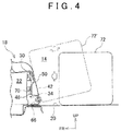
- FIG. 4 is a drawing showing a state when a loaded object 72 in the trunk 14 collides against the onboard battery 18. If the vehicle 10 is suddenly decelerated because of a forward collision or the like, the loaded object 72 in the trunk 14 forwardly moves by inertia, and collides against the case rear-surface member 42 of the onboard battery 18 located at the frontward position in the trunk 14. If receiving a great force from the loaded object 72, the case rear-surface member 42 is likely to move in the frontward direction. At this time, the case rear-surface member 42 is fixed at the lower edge thereof, but is not constrained at the upper edge thereof, and there is a gap between the ridge portion 46 and the assembly battery 22; thus the case rear-surface member 42 turns around the lower edge thereof.
- the ridge portion 46 comes into contact with the rear surface 34 of the assembly battery 22, particularly, with the wire harness holder 50 in the present embodiment, and this turning is then stopped.
- the terminal cover 48 having received the case rear-surface member 42 or force from the case rear-surface member 42 does not reach the electrode terminal 30, and thus the electrode terminal 30 receives no force.
- the portions in contact with each other between the wire harness holder 50 and the slope surface 70 of the ridge portion 46 become substantially parallel with each other in FIG. 4 . Accordingly, the wire harness holder 50 can receive force from the ridge portion 46 in a wider range in the vertical direction, thereby suppressing concentration of load.
- the rear surface of the battery case 24 becomes an inclined plane.
- an angle of inclination of the case rear-surface member 42 is 10° to 20°, particularly 10° to 15° relative to the perpendicular direction.
- An angle of rearward inclination of the slope surface 70 of the ridge portion in a normal state is configured to be correspondent to this angle.
- the loaded object 72 having collided moves along the rear surface of the battery case 24 inclined as illustrated by a loaded object 72' indicated in a long dashed short dashed line. Accordingly, part of the force at the time of collision of the loaded object 72 is released, thus reducing force to be applied to the onboard battery 18.
- Each electrode terminal 30 extends in the inside of each battery module 26; therefore, if a great force is applied to the electrode terminal 30, this force is transferred to the inside of the battery module 26, which may cause damage to the battery module 26.
- each battery module 26 is relatively rigid against an input from the other portions than the electrode terminal 30, and the ridge portion 46 is provided so that the force is received at the other portions than the electrode terminal 30, thereby preventing the battery module 26 from being damaged.
- the ridge portion 46 is brought into contact with the wire harness holder 50, thereby distributing the force to be transferred to the battery modules 26.
- the loaded object 72 does not always uniformly collide in the entire right and left direction of the battery case 24, and if the loaded object 72 collides against a part of the battery case 24, only the ridge portion 46 located in the vicinity of this part comes into contact with the wire harness holder 50. Since the wire harness holder 50 extends in the right and left direction, the wire harness holder 50 transfers the force received from the ridge portion 46 in the right and left direction, thereby transferring this force to as many battery modules 26 as possible. Through this configuration, the force to be received by the single battery module 26 is reduced. By providing the assembly battery 22 with a member like the wire harness holder 50 that extends in the right and left direction, and receives the force from the ridge portion 46, it is possible to distribute the force to as many battery modules 26 as possible.
- An onboard battery includes an assembly battery and a battery case accommodating the assembly battery.
- the battery case includes a surface member forming a surface that faces a terminal arrangement surface where electrode terminals of the assembly battery are arranged.
- This surface member includes a ridge portion rising toward the assembly battery.
- the ridge portion faces at least a part of the terminal arrangement surface in a manner as to avoid the electrode terminals. At the moment when the surface member including the ridge portion moves toward the assembly battery, the ridge portion comes into contact with the assembly battery before the surface member applies force to the electrode terminals.
Landscapes
- Chemical & Material Sciences (AREA)
- Engineering & Computer Science (AREA)
- Electrochemistry (AREA)
- General Chemical & Material Sciences (AREA)
- Chemical Kinetics & Catalysis (AREA)
- Mechanical Engineering (AREA)
- Transportation (AREA)
- Combustion & Propulsion (AREA)
- Aviation & Aerospace Engineering (AREA)
- Battery Mounting, Suspending (AREA)
- Arrangement Or Mounting Of Propulsion Units For Vehicles (AREA)
- Life Sciences & Earth Sciences (AREA)
- Sustainable Development (AREA)
- Sustainable Energy (AREA)
- Power Engineering (AREA)
Abstract
Description
- The present invention relates to an onboard battery mounted in a vehicle, and particularly, to protection of an onboard battery in collision of a vehicle.
- In vehicles, such as hybrid vehicles, equipped with electric motors as motors for driving vehicles, batteries to supply electric power to the electric motors are mounted. The batteries are disposed in front sections of trunks, for example. If vehicles including such batteries are suddenly decelerated, loaded objects in the trunks might forwardly move to collide against the batteries in some cases.
- Japanese Patent Application Publication
JP 2013-8524 A - Japanese Patent Application Publication
JP 2013-26111 A - In
JP 2013-8524 A - The present invention provides an onboard battery capable of suppressing increase in dimension of the battery, and suppressing force to be applied to electrode terminals from a case or the like.
- An aspect of the present invention relates to an onboard battery mounted in an vehicle. The onboard battery is mounted in a front section in a space located behind a rearmost seat of the vehicle. The onboard battery includes an assembly battery and a battery case accommodating the assembly battery. Electrode terminals of the battery are arranged on a rear surface of the assembly battery. The battery case includes a case rear-surface member forming a rear surface of the battery case, and is provided with a ridge portion that faces at least a part of the rear surface of the assembly battery in the frontward and rearward direction, and that rises toward the assembly battery. The ridge portion faces the rear surface of the assembly battery in a manner as to avoid the electrode terminals. When the case rear-surface member moves toward the assembly battery, the ridge portion comes into contact with the assembly battery before the case rear-surface member applies force to the electrode terminals.
- The ridge portion may face the rear surface of the assembly battery with a distance therebetween, and the case rear-surface member may be fixed at a lower edge of the case rear-surface member to a vehicle body.
- The ridge portion may include a slope surface tilting relative to the rear surface of the assembly battery, and, when the slope surface comes into contact with the assembly battery, the slope surface becomes parallel with a surface of the assembly battery in contact with the slope surface.
- A lower edge of the slope surface may be located closer to the assembly battery than an upper edge thereof in the frontward and rearward direction.
- An angle of rearward inclination of the slope surface of the ridge portion may be 10° to 20°, in particular 10° to 15°, relative to the rear surface of the assembly battery.
- By providing the ridge portion in a manner as to avoid the electrode terminals, it is possible to suppress contact of the battery case with the electrodes. The case rear-surface member is fixed at the lower edge thereof to the vehicle body with a distance between the ridge portion and the rear surface of the assembly battery, thereby bringing the case rear-surface member to be forwardly inclined at the moment when a loaded object in the trunk collides against the case rear-surface member. The loaded object in the trunk moves along the case rear-surface member forwardly inclined, thereby reducing impact to be received by the assembly battery.
- Features, advantages, and technical and industrial significance of exemplary embodiments of the invention will be described below with reference to the accompanying drawings, in which like numerals denote like elements, and wherein:
-
FIG. 1 is a side sectional view showing a main part of a rear section of a vehicle; -
FIG. 2 is a perspective view showing an onboard battery, particularly an assembly battery and a battery case; -
FIG. 3 is a drawing showing a sectional view of the onboard battery; and -
FIG. 4 is a sectional view showing a state in which a loaded object in a trunk collides against the onboard battery. - Embodiments of the present invention will be described with reference to drawings hereinafter.
FIG. 1 is a side perspective view of a rear section of anvehicle 10 viewed sideward, equipped with an electric motor as a motor for driving a vehicle, such as a hybrid vehicle, and showing a main part of thevehicle 10. InFIG. 1 , a direction indicated by an arrow FR represents a frontward direction of thevehicle 10, and a direction indicated by an arrow UP represents an upward direction thereof. In the following drawings, the frontward direction and the upward direction of thevehicle 10 are indicated by using the arrows FR, UP, respectively. In the following description, terms expressing directions and orientations, such as frontward, rearward, right, left, upward, downward, and sideward, denote directions and orientations with reference to thevehicle 10 otherwise mentioned. - The
vehicle 10 is a passenger vehicle including front seats (not shown) andrear seats 12. Thevehicle 10 further includes atrunk 14 behind therear seats 12. Aback face 16 of eachrear seat 12 defines a front end of thetrunk 14. Abattery 18 is mounted in a front section of thetrunk 14. Thebattery 18 is referred to as anonboard battery 18 hereinafter. A partition wall may be provided between a space where theonboard battery 18 is accommodated and a space where luggage is actually loaded in order to partition these spaces. In such an aspect, the space used for accommodating theonboard battery 18 and the space used for loading the luggage are corresponding to thetrunk 14 of the present embodiment. In the present embodiment, a passenger vehicle including front seats andrear seats 12 is exemplified, and a space behind therear seats 12 is treated as thetrunk 14, but in a vehicle including only front seats, the front seats are equivalent to rearmost seats of the vehicle, and thus a space behind the seats is corresponding to thetrunk 14. Theonboard battery 18 may be disposed immediately behind therear seats 12, and inFIG. 1 , theonboard battery 18 is placed on afloor surface 20 of the trunk 14 (hereinafter, referred to as a trunk floor surface 20). This installation position of theonboard battery 18 is correspondent to a position between wheel houses of right and left rear wheels. Theonboard battery 18 includes anassembly battery 22, and abattery case 24 where theassembly battery 22 is accommodated. Electric power is supplied from theonboard battery 18 to the electric motor for driving a vehicle, or theonboard battery 18 is charged with electric power generated by the electric motor through regenerative braking or the like. -
FIG. 2 is an exploded perspective view showing a configuration of a main part of theonboard battery 18. Theassembly battery 22 is formed bystacking battery modules 26, each having a substantially rectangular shape with a thickness, in a thickness direction of the battery modules. The stacking direction of thebattery modules 26 coincides with the right and left direction when theonboard battery 18 is mounted in thevehicle 10. Eachbattery module 26 includes plural, for example, six cells connected in series, and generally has a substantially rectangular shape with a thickness. A positive electrode and a negative electrode, and an electrolytic solution are included in eachbattery module 26,electrode terminals battery module 26. Eachelectrode terminal 28 is a terminal provided to a front shorter side of each battery module, and eachelectrode terminal 30 is a terminal provided to a rear shorter side of each battery module. Each of theelectrode terminals 28 and each of theelectrode terminals 30 are connected to respective electrodes at both ends of each cell connected in series in thebattery module 26. Theassembly battery 22 has a substantially rectangular parallelepiped shape, a surface facing frontward of this rectangular parallelepiped shape is referred to as afront surface 32, and a surface facing rearward thereof is referred to as arear surface 34. Thefront surface 32 and therear surface 34 are substantially perpendicular surfaces. Theelectrode terminals 28 are arranged at an upper position along an upper edge of thefront surface 32, and theelectrode terminals 30 are arranged at an upper position along an upper edge of therear surface 34. - The
battery case 24 accommodating theassembly battery 22 includes anupper case 36 and alower case 38. Theupper case 36 is integrally formed of a steel plate, and includes a case front-surface member 40 so located as to face thefront surface 32 of theassembly battery 22, a case rear-surface member 42 so located as to face therear surface 34 thereof, and a case upper-surface member 44 so located as to face an upper surface of theassembly battery 22. The case front-surface member 40 and the case rear-surface member 42 are disposed substantially perpendicularly, and the case upper-surface member 44 is disposed substantially horizontally. Thelower case 38 faces a lower surface of theassembly battery 22. Theupper case 36 and thelower case 38 form a tube having a substantially rectangular section, and both ends of this tube are closed with not-shown members. Thebattery case 24 is formed by the members disposed at the both ends of the tube, theupper case 36, and thelower case 38. Aridge portion 46 is provided to an inner side of the case rear-surface member 42, that is, to a surface of the case rear-surface member 42 that faces therear surface 34 of theassembly battery 22. Theridge portion 46 is disposed in a manner as to avoid theelectrode terminals 30, particularly in a manner as to face a portion of therear surface 34 where theelectrode terminals 30 are not disposed, specifically, below theelectrode terminals 30. Theridge portion 46 maybe so disposed as to extend across an entire range that is substantially the same as a range where theelectrode terminals 30 are arranged in the right and left direction. Theridge portion 46 may be disposed in a part of the region where theelectrode terminals 30 are arranged, or theridge portions 46 may be disposed with intervals in the right and left direction. -
FIG. 3 is a longitudinal sectional view showing a more detailed structure of theonboard battery 18. Theassembly battery 22 includes aterminal cover 48 and awire harness holder 50 that extend in the right and left direction along therear surface 34. Theterminal cover 48 and thewire harness holder 50 may be provided in the entire right and left direction of theassembly battery 22. Theterminal cover 48 covers a back side of eachelectrode terminal 30. Thewire harness holder 50 defines a space between thewire harness holder 50 and thebattery module 26, and a wire harness to transmit signals to various sensors is held in this space. Theterminal cover 48 and thewire harness holder 50 may be formed as an integral resin component, and are attached to thebattery modules 26. Therear surface 34 of theassembly battery 22 is formed by rear end surfaces of thebattery modules 26, theterminal cover 48, and thewire harness holder 50. - An
air guiding plate 52 is fixed to a corner portion defined by the case rear-surface member 42 and the case upper-surface member 44 through welding or the like. A ceiling surface of theupper case 36 formed by theair guiding plate 52 and the case upper-surface member 44 has a substantially protruding shape. The projecting portion in a protruding shape is so disposed to be correspondent to the upper surface of theassembly battery 22, and an upperair guiding passage 54 is formed between the projecting portion and theassembly battery 22. Theair guiding plate 52 restricts a region where air flow passes to the upper surface of thebattery module 26. The air flow passes through the upperair guiding passage 54 in a direction of penetrating the drawing ofFIG. 3 , and this air flow cools theassembly battery 22. Thelower case 38 has a recessed portion so formed as to be correspondent to the lower surface of theassembly battery 22. There is a distance between abottom surface 56 of the recessed portion and the lower surface of theassembly battery 22. A front edge and a rear edge of the lower surface of theassembly battery 22 are supported byedge portions lower case 38 defines a lowerair guiding passage 62 between the recessed portion and the lower surface of theassembly battery 22. The air flow passes through the lowerair guiding passage 62 in the direction of penetrating the drawing ofFIG. 3 , and this air flow cools theassembly battery 22. - The
lower case 38 is fixed to a vehicle body through welding or the like.FIG. 3 illustrates that thelower case 38 is fixed at theedge portion 60 to across member 64 of the vehicle body. Thelower case 38 is fixed at the other plural positions to the vehicle body. A height of the upper surface of thecross member 64 substantially coincides with a height of thetrunk floor surface 20. Hence, a height of theedge portion 60 of thelower case 38, that is, a height of the lower surface of theassembly battery 22 is substantially the same as a level of thetrunk floor surface 20. - The
upper case 36 and thelower case 38 are joined to each other at the front edges and the rear edges thereof. At the rear edges, a lower edge of the case rear-surface member 42 is joined to plural L-shapedbrackets 66 welded to theedge portion 60 of thelower case 38 withbolts 68. Thebrackets 66 may be integrated with thelower case 38 using a single steel plate. The case rear-surface member 42 is fixed at the lower edge thereof to the vehicle body through thelower case 38 and thebrackets 66. The case rear-surface member 42 may be fixed at the lower edge thereof directly to the vehicle body, or may be fixed through brackets directly fixed to the vehicle body. The lower edge of the case rear-surface member 42 is located at substantially the same level as that of thetrunk floor surface 20. With respect to the positional relation in the vertical direction, the lower edge of the case rear-surface member 42 and thetrunk floor surface 20 are unnecessary to be located at the same height, and thetrunk floor surface 20 may be located at a higher level, for example. - The
ridge portion 46 is fixed to the case rear-surface member 42 through welding or the like. Theridge portion 46 includes abackwardly slope surface 70 that faces therear surface 34 of theassembly battery 22. Thissurface 70 is referred to as aslope surface 70. Theslope surface 70 is apart from therear surface 34, and alower edge 70L of theslope surface 70 is located closer to theassembly battery 22 than anupper edge 70U thereof in the frontward and rearward direction. The plate member constituting theridge portion 46 is fixed together with the plate member forming the case rear-surface member to thebrackets 66 with thebolts 68. -
FIG. 4 is a drawing showing a state when a loadedobject 72 in thetrunk 14 collides against theonboard battery 18. If thevehicle 10 is suddenly decelerated because of a forward collision or the like, the loadedobject 72 in thetrunk 14 forwardly moves by inertia, and collides against the case rear-surface member 42 of theonboard battery 18 located at the frontward position in thetrunk 14. If receiving a great force from the loadedobject 72, the case rear-surface member 42 is likely to move in the frontward direction. At this time, the case rear-surface member 42 is fixed at the lower edge thereof, but is not constrained at the upper edge thereof, and there is a gap between theridge portion 46 and theassembly battery 22; thus the case rear-surface member 42 turns around the lower edge thereof. If the case rear-surface member 42 turns in the forwardly tilting direction, theridge portion 46 comes into contact with therear surface 34 of theassembly battery 22, particularly, with thewire harness holder 50 in the present embodiment, and this turning is then stopped. At this time, theterminal cover 48 having received the case rear-surface member 42 or force from the case rear-surface member 42 does not reach theelectrode terminal 30, and thus theelectrode terminal 30 receives no force. Meanwhile, the portions in contact with each other between thewire harness holder 50 and theslope surface 70 of theridge portion 46 become substantially parallel with each other inFIG. 4 . Accordingly, thewire harness holder 50 can receive force from theridge portion 46 in a wider range in the vertical direction, thereby suppressing concentration of load. - If the case rear-
surface member 42 tilts frontward, the rear surface of thebattery case 24 becomes an inclined plane. When theridge portion 46 comes into contact with therear surface 34 of theassembly battery 22, an angle of inclination of the case rear-surface member 42 is 10° to 20°, particularly 10° to 15° relative to the perpendicular direction. An angle of rearward inclination of theslope surface 70 of the ridge portion in a normal state is configured to be correspondent to this angle. When the case rear-surface member 42 tilts frontward, the loadedobject 72 having collided moves along the rear surface of thebattery case 24 inclined as illustrated by a loaded object 72' indicated in a long dashed short dashed line. Accordingly, part of the force at the time of collision of the loadedobject 72 is released, thus reducing force to be applied to theonboard battery 18. - Each
electrode terminal 30 extends in the inside of eachbattery module 26; therefore, if a great force is applied to theelectrode terminal 30, this force is transferred to the inside of thebattery module 26, which may cause damage to thebattery module 26. To counter this, eachbattery module 26 is relatively rigid against an input from the other portions than theelectrode terminal 30, and theridge portion 46 is provided so that the force is received at the other portions than theelectrode terminal 30, thereby preventing thebattery module 26 from being damaged. In theonboard battery 18, theridge portion 46 is brought into contact with thewire harness holder 50, thereby distributing the force to be transferred to thebattery modules 26. The loadedobject 72 does not always uniformly collide in the entire right and left direction of thebattery case 24, and if the loadedobject 72 collides against a part of thebattery case 24, only theridge portion 46 located in the vicinity of this part comes into contact with thewire harness holder 50. Since thewire harness holder 50 extends in the right and left direction, thewire harness holder 50 transfers the force received from theridge portion 46 in the right and left direction, thereby transferring this force to asmany battery modules 26 as possible. Through this configuration, the force to be received by thesingle battery module 26 is reduced. By providing theassembly battery 22 with a member like thewire harness holder 50 that extends in the right and left direction, and receives the force from theridge portion 46, it is possible to distribute the force to asmany battery modules 26 as possible. - Another embodiment according to the present invention will be described. An onboard battery according to another embodiment includes an assembly battery and a battery case accommodating the assembly battery. The battery case includes a surface member forming a surface that faces a terminal arrangement surface where electrode terminals of the assembly battery are arranged. This surface member includes a ridge portion rising toward the assembly battery. The ridge portion faces at least a part of the terminal arrangement surface in a manner as to avoid the electrode terminals. At the moment when the surface member including the ridge portion moves toward the assembly battery, the ridge portion comes into contact with the assembly battery before the surface member applies force to the electrode terminals.
Claims (5)
- An onboard battery (18) to be mounted in a front section of a space (14) located behind a rearmost seat (12) of a vehicle (10), comprising:an assembly battery (22) including electrode terminals (30) arranged on a rear surface (34) of the assembly battery (22) in a vehicle frontward and rearward direction; anda battery case (24) accommodating the assembly battery (22),characterized in thata case rear-surface member (42) forming a rear surface of the battery case (24) is provided with a ridge portion (46) that faces at least a part of the rear surface (34) of the assembly battery (22) in the vehicle frontward and rearward direction in a manner as to avoid the electrode terminals (30), the ridge portion (46) rising toward the assembly battery (22), and,when the case rear-surface member (42) is moved toward the assembly battery (22) by an external force, the ridge portion (46) comes into contact with the assembly battery (22) before the case rear-surface member (42) applies force to the electrode terminals (30).
- The onboard battery (18) according to claim 1, characterized in that
the ridge portion (46) faces the rear surface (34) of the assembly battery (22) with a distance therebetween, and the case rear-surface member (42) is fixable at a lower edge of the case rear-surface member (42) to a vehicle body. - The onboard battery (18) according to claim 1 or 2, characterized in that
the ridge portion (46) includes a slope surface (70) tilting relative to the rear surface (34) of the assembly battery (22), and
when the slope surface (70) comes into contact with the assembly battery (22), the slope surface (70) becomes parallel with a surface of the assembly battery (22) in contact with the slope surface (70). - The onboard battery (18) according to claim 3, characterized in that
a lower edge (70L) of the slope surface (70) is located closer to the assembly battery (22) than an upper edge (70U) thereof in the frontward and rearward direction. - The onboard battery (18) according to claim 3 or 4, characterized in that
an angle of rearward inclination of the slope surface (70) of the ridge portion (46) is 10° to 20°, in particular 10° to 15°, relative to the rear surface (34) of the assembly battery (22).
Applications Claiming Priority (1)
| Application Number | Priority Date | Filing Date | Title |
|---|---|---|---|
| JP2015032023A JP6135694B2 (en) | 2015-02-20 | 2015-02-20 | Car battery |
Publications (2)
| Publication Number | Publication Date |
|---|---|
| EP3079184A1 true EP3079184A1 (en) | 2016-10-12 |
| EP3079184B1 EP3079184B1 (en) | 2017-11-22 |
Family
ID=55361434
Family Applications (1)
| Application Number | Title | Priority Date | Filing Date |
|---|---|---|---|
| EP16156304.4A Active EP3079184B1 (en) | 2015-02-20 | 2016-02-18 | Onboard battery |
Country Status (5)
| Country | Link |
|---|---|
| US (1) | US9837645B2 (en) |
| EP (1) | EP3079184B1 (en) |
| JP (1) | JP6135694B2 (en) |
| KR (1) | KR101810091B1 (en) |
| CN (1) | CN105914314B (en) |
Families Citing this family (12)
| Publication number | Priority date | Publication date | Assignee | Title |
|---|---|---|---|---|
| JP5870992B2 (en) * | 2013-12-25 | 2016-03-01 | トヨタ自動車株式会社 | Battery mounting structure for vehicles |
| JP6504143B2 (en) * | 2016-11-15 | 2019-04-24 | トヨタ自動車株式会社 | Battery pack |
| US9963028B1 (en) * | 2017-02-21 | 2018-05-08 | Ford Global Technologies, Llc | Battery support structure for electrified vehicle |
| JP6997525B2 (en) * | 2017-03-29 | 2022-01-17 | 株式会社Subaru | In-vehicle battery |
| WO2018211351A1 (en) | 2017-05-19 | 2018-11-22 | Semiconductor Energy Laboratory Co., Ltd. | Semiconductor device, display device, and method for manufacturing semiconductor device |
| KR102119152B1 (en) | 2017-12-12 | 2020-06-04 | 삼성에스디아이 주식회사 | Battery Pack |
| JP7006514B2 (en) * | 2018-06-07 | 2022-02-10 | トヨタ自動車株式会社 | Battery mounting structure |
| US10710527B2 (en) * | 2018-07-10 | 2020-07-14 | Kawasaki Jukogyo Kabushiki Kaisha | Utility vehicle |
| JP7316087B2 (en) * | 2019-04-26 | 2023-07-27 | 株式会社Subaru | Battery storage structure |
| JP7264070B2 (en) * | 2020-01-20 | 2023-04-25 | トヨタ自動車株式会社 | Mounting structure of power storage device |
| CN115461238B (en) * | 2020-04-27 | 2025-11-25 | 日产自动车株式会社 | Protector structure for electrical components |
| JP7769512B2 (en) * | 2021-11-01 | 2025-11-13 | 株式会社Subaru | Battery module protection structure |
Citations (2)
| Publication number | Priority date | Publication date | Assignee | Title |
|---|---|---|---|---|
| JP2013008524A (en) | 2011-06-23 | 2013-01-10 | Toyota Motor Corp | Vehicle power supply device |
| JP2013026111A (en) | 2011-07-25 | 2013-02-04 | Toyota Motor Corp | Protection structure of terminal, and vehicle |
Family Cites Families (18)
| Publication number | Priority date | Publication date | Assignee | Title |
|---|---|---|---|---|
| JPH0781432A (en) * | 1993-09-20 | 1995-03-28 | Nissan Motor Co Ltd | Battery fixing structure for electric vehicles |
| JPH07179185A (en) * | 1993-12-24 | 1995-07-18 | Nissan Motor Co Ltd | Body mounting structure of battery floor of electric vehicle |
| JP3777981B2 (en) * | 2000-04-13 | 2006-05-24 | トヨタ自動車株式会社 | Vehicle power supply |
| JP2001313018A (en) * | 2000-04-28 | 2001-11-09 | Toyota Motor Corp | Power supply device and method of manufacturing the same |
| JP4576931B2 (en) * | 2004-08-27 | 2010-11-10 | トヨタ自動車株式会社 | Electrical equipment mounting structure |
| JP4334501B2 (en) * | 2005-04-28 | 2009-09-30 | 三洋電機株式会社 | Power supply for vehicle |
| JP5082454B2 (en) * | 2007-01-16 | 2012-11-28 | トヨタ自動車株式会社 | Fuel cell module for vehicles |
| WO2011148687A1 (en) * | 2010-05-26 | 2011-12-01 | スズキ株式会社 | Structure for vehicle body rear portion |
| US9263713B2 (en) * | 2010-05-26 | 2016-02-16 | Samsung Sdi Co., Ltd. | Battery pack |
| JP2012005165A (en) * | 2010-06-14 | 2012-01-05 | Sumitomo Wiring Syst Ltd | Electric wire protection tool with long object fixing part |
| JP5071538B2 (en) * | 2010-09-03 | 2012-11-14 | トヨタ自動車株式会社 | Battery mounting structure for vehicles |
| JP5617492B2 (en) * | 2010-09-29 | 2014-11-05 | トヨタ自動車株式会社 | Battery mounting structure for vehicles |
| JP5403290B2 (en) * | 2011-03-31 | 2014-01-29 | 三菱自動車工業株式会社 | Electric vehicle battery mounting structure |
| JP5733089B2 (en) * | 2011-08-01 | 2015-06-10 | トヨタ自動車株式会社 | Power storage device mounting structure |
| WO2013054373A1 (en) * | 2011-10-11 | 2013-04-18 | トヨタ自動車株式会社 | Structure for mounting electric power storage device |
| DE102012105140B4 (en) | 2012-06-14 | 2021-09-09 | Dr. Ing. H.C. F. Porsche Aktiengesellschaft | Motor vehicle with a body shell, a battery module and a device for fastening the battery module to the body shell of the motor vehicle |
| DE102012108762A1 (en) * | 2012-09-18 | 2014-03-20 | Dr. Ing. H.C. F. Porsche Aktiengesellschaft | battery means |
| JP6136187B2 (en) * | 2012-10-16 | 2017-05-31 | トヨタ自動車株式会社 | Battery mounting structure for vehicles |
-
2015
- 2015-02-20 JP JP2015032023A patent/JP6135694B2/en active Active
-
2016
- 2016-02-18 EP EP16156304.4A patent/EP3079184B1/en active Active
- 2016-02-18 KR KR1020160019056A patent/KR101810091B1/en active Active
- 2016-02-19 CN CN201610092756.2A patent/CN105914314B/en active Active
- 2016-02-19 US US15/047,925 patent/US9837645B2/en active Active
Patent Citations (2)
| Publication number | Priority date | Publication date | Assignee | Title |
|---|---|---|---|---|
| JP2013008524A (en) | 2011-06-23 | 2013-01-10 | Toyota Motor Corp | Vehicle power supply device |
| JP2013026111A (en) | 2011-07-25 | 2013-02-04 | Toyota Motor Corp | Protection structure of terminal, and vehicle |
Also Published As
| Publication number | Publication date |
|---|---|
| US9837645B2 (en) | 2017-12-05 |
| KR101810091B1 (en) | 2017-12-18 |
| EP3079184B1 (en) | 2017-11-22 |
| US20160248059A1 (en) | 2016-08-25 |
| JP6135694B2 (en) | 2017-05-31 |
| KR20160102350A (en) | 2016-08-30 |
| CN105914314A (en) | 2016-08-31 |
| JP2016154113A (en) | 2016-08-25 |
| CN105914314B (en) | 2018-10-12 |
Similar Documents
| Publication | Publication Date | Title |
|---|---|---|
| EP3079184B1 (en) | Onboard battery | |
| EP3412486B1 (en) | Battery mounting structure | |
| CN107546346B (en) | Vehicle-mounted storage battery | |
| US9873456B2 (en) | Onboard battery for vehicle | |
| US10189371B2 (en) | Electrically-powered vehicle | |
| JP5829706B2 (en) | Automotive battery | |
| US20170087972A1 (en) | Vehicle body structure and onboard battery for vehicle | |
| CN114426065B (en) | Vehicles and vehicle substructures | |
| US20130199864A1 (en) | Vehicle with traction battery capable of absorbing crash energy | |
| US10439183B2 (en) | Impact absorbing elements attached to the outer surface of a battery enclosure | |
| WO2013171797A1 (en) | Vehicle | |
| JP2018170101A (en) | Automotive battery | |
| US11450874B2 (en) | Fuel cell unit | |
| JP2018083524A (en) | On-vehicle battery pack | |
| JP5997468B2 (en) | Hybrid car | |
| JP7435034B2 (en) | Vehicles equipped with lithium-ion batteries | |
| JP6525657B2 (en) | Automotive battery | |
| US20240116353A1 (en) | Battery support frame structure | |
| US20220234432A1 (en) | Power storage device | |
| CN105818662A (en) | Electric vehicle | |
| KR20260032211A (en) | Vehicle battery case |
Legal Events
| Date | Code | Title | Description |
|---|---|---|---|
| PUAI | Public reference made under article 153(3) epc to a published international application that has entered the european phase |
Free format text: ORIGINAL CODE: 0009012 |
|
| 17P | Request for examination filed |
Effective date: 20160218 |
|
| AK | Designated contracting states |
Kind code of ref document: A1 Designated state(s): AL AT BE BG CH CY CZ DE DK EE ES FI FR GB GR HR HU IE IS IT LI LT LU LV MC MK MT NL NO PL PT RO RS SE SI SK SM TR |
|
| AX | Request for extension of the european patent |
Extension state: BA ME |
|
| GRAP | Despatch of communication of intention to grant a patent |
Free format text: ORIGINAL CODE: EPIDOSNIGR1 |
|
| STAA | Information on the status of an ep patent application or granted ep patent |
Free format text: STATUS: GRANT OF PATENT IS INTENDED |
|
| RIC1 | Information provided on ipc code assigned before grant |
Ipc: B60K 1/04 20060101ALI20170427BHEP Ipc: H01M 2/10 20060101AFI20170427BHEP |
|
| INTG | Intention to grant announced |
Effective date: 20170531 |
|
| RIN1 | Information on inventor provided before grant (corrected) |
Inventor name: KATAYAMA, YUSUKE Inventor name: FUKUSAKO, NAOKI Inventor name: NAGAMINE, KOICHI |
|
| GRAS | Grant fee paid |
Free format text: ORIGINAL CODE: EPIDOSNIGR3 |
|
| GRAA | (expected) grant |
Free format text: ORIGINAL CODE: 0009210 |
|
| STAA | Information on the status of an ep patent application or granted ep patent |
Free format text: STATUS: THE PATENT HAS BEEN GRANTED |
|
| AK | Designated contracting states |
Kind code of ref document: B1 Designated state(s): AL AT BE BG CH CY CZ DE DK EE ES FI FR GB GR HR HU IE IS IT LI LT LU LV MC MK MT NL NO PL PT RO RS SE SI SK SM TR |
|
| RAP1 | Party data changed (applicant data changed or rights of an application transferred) |
Owner name: TOYOTA JIDOSHA KABUSHIKI KAISHA |
|
| REG | Reference to a national code |
Ref country code: GB Ref legal event code: FG4D |
|
| REG | Reference to a national code |
Ref country code: CH Ref legal event code: EP |
|
| REG | Reference to a national code |
Ref country code: IE Ref legal event code: FG4D |
|
| REG | Reference to a national code |
Ref country code: AT Ref legal event code: REF Ref document number: 949173 Country of ref document: AT Kind code of ref document: T Effective date: 20171215 |
|
| RAP2 | Party data changed (patent owner data changed or rights of a patent transferred) |
Owner name: TOYOTA JIDOSHA KABUSHIKI KAISHA |
|
| REG | Reference to a national code |
Ref country code: DE Ref legal event code: R096 Ref document number: 602016000841 Country of ref document: DE |
|
| REG | Reference to a national code |
Ref country code: FR Ref legal event code: PLFP Year of fee payment: 3 |
|
| REG | Reference to a national code |
Ref country code: NL Ref legal event code: MP Effective date: 20171122 |
|
| REG | Reference to a national code |
Ref country code: LT Ref legal event code: MG4D |
|
| REG | Reference to a national code |
Ref country code: AT Ref legal event code: MK05 Ref document number: 949173 Country of ref document: AT Kind code of ref document: T Effective date: 20171122 |
|
| PG25 | Lapsed in a contracting state [announced via postgrant information from national office to epo] |
Ref country code: NL Free format text: LAPSE BECAUSE OF FAILURE TO SUBMIT A TRANSLATION OF THE DESCRIPTION OR TO PAY THE FEE WITHIN THE PRESCRIBED TIME-LIMIT Effective date: 20171122 Ref country code: FI Free format text: LAPSE BECAUSE OF FAILURE TO SUBMIT A TRANSLATION OF THE DESCRIPTION OR TO PAY THE FEE WITHIN THE PRESCRIBED TIME-LIMIT Effective date: 20171122 Ref country code: LT Free format text: LAPSE BECAUSE OF FAILURE TO SUBMIT A TRANSLATION OF THE DESCRIPTION OR TO PAY THE FEE WITHIN THE PRESCRIBED TIME-LIMIT Effective date: 20171122 Ref country code: ES Free format text: LAPSE BECAUSE OF FAILURE TO SUBMIT A TRANSLATION OF THE DESCRIPTION OR TO PAY THE FEE WITHIN THE PRESCRIBED TIME-LIMIT Effective date: 20171122 Ref country code: NO Free format text: LAPSE BECAUSE OF FAILURE TO SUBMIT A TRANSLATION OF THE DESCRIPTION OR TO PAY THE FEE WITHIN THE PRESCRIBED TIME-LIMIT Effective date: 20180222 Ref country code: SE Free format text: LAPSE BECAUSE OF FAILURE TO SUBMIT A TRANSLATION OF THE DESCRIPTION OR TO PAY THE FEE WITHIN THE PRESCRIBED TIME-LIMIT Effective date: 20171122 |
|
| PG25 | Lapsed in a contracting state [announced via postgrant information from national office to epo] |
Ref country code: LV Free format text: LAPSE BECAUSE OF FAILURE TO SUBMIT A TRANSLATION OF THE DESCRIPTION OR TO PAY THE FEE WITHIN THE PRESCRIBED TIME-LIMIT Effective date: 20171122 Ref country code: HR Free format text: LAPSE BECAUSE OF FAILURE TO SUBMIT A TRANSLATION OF THE DESCRIPTION OR TO PAY THE FEE WITHIN THE PRESCRIBED TIME-LIMIT Effective date: 20171122 Ref country code: BG Free format text: LAPSE BECAUSE OF FAILURE TO SUBMIT A TRANSLATION OF THE DESCRIPTION OR TO PAY THE FEE WITHIN THE PRESCRIBED TIME-LIMIT Effective date: 20180222 Ref country code: GR Free format text: LAPSE BECAUSE OF FAILURE TO SUBMIT A TRANSLATION OF THE DESCRIPTION OR TO PAY THE FEE WITHIN THE PRESCRIBED TIME-LIMIT Effective date: 20180223 Ref country code: RS Free format text: LAPSE BECAUSE OF FAILURE TO SUBMIT A TRANSLATION OF THE DESCRIPTION OR TO PAY THE FEE WITHIN THE PRESCRIBED TIME-LIMIT Effective date: 20171122 Ref country code: AT Free format text: LAPSE BECAUSE OF FAILURE TO SUBMIT A TRANSLATION OF THE DESCRIPTION OR TO PAY THE FEE WITHIN THE PRESCRIBED TIME-LIMIT Effective date: 20171122 |
|
| PG25 | Lapsed in a contracting state [announced via postgrant information from national office to epo] |
Ref country code: DK Free format text: LAPSE BECAUSE OF FAILURE TO SUBMIT A TRANSLATION OF THE DESCRIPTION OR TO PAY THE FEE WITHIN THE PRESCRIBED TIME-LIMIT Effective date: 20171122 Ref country code: EE Free format text: LAPSE BECAUSE OF FAILURE TO SUBMIT A TRANSLATION OF THE DESCRIPTION OR TO PAY THE FEE WITHIN THE PRESCRIBED TIME-LIMIT Effective date: 20171122 Ref country code: CY Free format text: LAPSE BECAUSE OF FAILURE TO SUBMIT A TRANSLATION OF THE DESCRIPTION OR TO PAY THE FEE WITHIN THE PRESCRIBED TIME-LIMIT Effective date: 20171122 Ref country code: SK Free format text: LAPSE BECAUSE OF FAILURE TO SUBMIT A TRANSLATION OF THE DESCRIPTION OR TO PAY THE FEE WITHIN THE PRESCRIBED TIME-LIMIT Effective date: 20171122 Ref country code: CZ Free format text: LAPSE BECAUSE OF FAILURE TO SUBMIT A TRANSLATION OF THE DESCRIPTION OR TO PAY THE FEE WITHIN THE PRESCRIBED TIME-LIMIT Effective date: 20171122 |
|
| REG | Reference to a national code |
Ref country code: DE Ref legal event code: R097 Ref document number: 602016000841 Country of ref document: DE |
|
| PG25 | Lapsed in a contracting state [announced via postgrant information from national office to epo] |
Ref country code: RO Free format text: LAPSE BECAUSE OF FAILURE TO SUBMIT A TRANSLATION OF THE DESCRIPTION OR TO PAY THE FEE WITHIN THE PRESCRIBED TIME-LIMIT Effective date: 20171122 Ref country code: SM Free format text: LAPSE BECAUSE OF FAILURE TO SUBMIT A TRANSLATION OF THE DESCRIPTION OR TO PAY THE FEE WITHIN THE PRESCRIBED TIME-LIMIT Effective date: 20171122 Ref country code: IT Free format text: LAPSE BECAUSE OF FAILURE TO SUBMIT A TRANSLATION OF THE DESCRIPTION OR TO PAY THE FEE WITHIN THE PRESCRIBED TIME-LIMIT Effective date: 20171122 Ref country code: PL Free format text: LAPSE BECAUSE OF FAILURE TO SUBMIT A TRANSLATION OF THE DESCRIPTION OR TO PAY THE FEE WITHIN THE PRESCRIBED TIME-LIMIT Effective date: 20171122 |
|
| PG25 | Lapsed in a contracting state [announced via postgrant information from national office to epo] |
Ref country code: MC Free format text: LAPSE BECAUSE OF FAILURE TO SUBMIT A TRANSLATION OF THE DESCRIPTION OR TO PAY THE FEE WITHIN THE PRESCRIBED TIME-LIMIT Effective date: 20171122 |
|
| PLBE | No opposition filed within time limit |
Free format text: ORIGINAL CODE: 0009261 |
|
| REG | Reference to a national code |
Ref country code: DE Ref legal event code: R084 Ref document number: 602016000841 Country of ref document: DE |
|
| STAA | Information on the status of an ep patent application or granted ep patent |
Free format text: STATUS: NO OPPOSITION FILED WITHIN TIME LIMIT |
|
| REG | Reference to a national code |
Ref country code: GB Ref legal event code: 746 Effective date: 20180928 |
|
| 26N | No opposition filed |
Effective date: 20180823 |
|
| REG | Reference to a national code |
Ref country code: IE Ref legal event code: MM4A |
|
| REG | Reference to a national code |
Ref country code: BE Ref legal event code: MM Effective date: 20180228 |
|
| PG25 | Lapsed in a contracting state [announced via postgrant information from national office to epo] |
Ref country code: LU Free format text: LAPSE BECAUSE OF NON-PAYMENT OF DUE FEES Effective date: 20180218 Ref country code: SI Free format text: LAPSE BECAUSE OF FAILURE TO SUBMIT A TRANSLATION OF THE DESCRIPTION OR TO PAY THE FEE WITHIN THE PRESCRIBED TIME-LIMIT Effective date: 20171122 |
|
| PG25 | Lapsed in a contracting state [announced via postgrant information from national office to epo] |
Ref country code: IE Free format text: LAPSE BECAUSE OF NON-PAYMENT OF DUE FEES Effective date: 20180218 |
|
| PG25 | Lapsed in a contracting state [announced via postgrant information from national office to epo] |
Ref country code: BE Free format text: LAPSE BECAUSE OF NON-PAYMENT OF DUE FEES Effective date: 20180228 |
|
| REG | Reference to a national code |
Ref country code: CH Ref legal event code: PL |
|
| PG25 | Lapsed in a contracting state [announced via postgrant information from national office to epo] |
Ref country code: LI Free format text: LAPSE BECAUSE OF NON-PAYMENT OF DUE FEES Effective date: 20190228 Ref country code: CH Free format text: LAPSE BECAUSE OF NON-PAYMENT OF DUE FEES Effective date: 20190228 |
|
| PG25 | Lapsed in a contracting state [announced via postgrant information from national office to epo] |
Ref country code: MT Free format text: LAPSE BECAUSE OF NON-PAYMENT OF DUE FEES Effective date: 20180218 |
|
| PG25 | Lapsed in a contracting state [announced via postgrant information from national office to epo] |
Ref country code: TR Free format text: LAPSE BECAUSE OF FAILURE TO SUBMIT A TRANSLATION OF THE DESCRIPTION OR TO PAY THE FEE WITHIN THE PRESCRIBED TIME-LIMIT Effective date: 20171122 |
|
| PG25 | Lapsed in a contracting state [announced via postgrant information from national office to epo] |
Ref country code: PT Free format text: LAPSE BECAUSE OF FAILURE TO SUBMIT A TRANSLATION OF THE DESCRIPTION OR TO PAY THE FEE WITHIN THE PRESCRIBED TIME-LIMIT Effective date: 20171122 |
|
| PG25 | Lapsed in a contracting state [announced via postgrant information from national office to epo] |
Ref country code: HU Free format text: LAPSE BECAUSE OF FAILURE TO SUBMIT A TRANSLATION OF THE DESCRIPTION OR TO PAY THE FEE WITHIN THE PRESCRIBED TIME-LIMIT; INVALID AB INITIO Effective date: 20160218 Ref country code: MK Free format text: LAPSE BECAUSE OF NON-PAYMENT OF DUE FEES Effective date: 20171122 |
|
| PG25 | Lapsed in a contracting state [announced via postgrant information from national office to epo] |
Ref country code: AL Free format text: LAPSE BECAUSE OF FAILURE TO SUBMIT A TRANSLATION OF THE DESCRIPTION OR TO PAY THE FEE WITHIN THE PRESCRIBED TIME-LIMIT Effective date: 20171122 Ref country code: IS Free format text: LAPSE BECAUSE OF FAILURE TO SUBMIT A TRANSLATION OF THE DESCRIPTION OR TO PAY THE FEE WITHIN THE PRESCRIBED TIME-LIMIT Effective date: 20180322 |
|
| REG | Reference to a national code |
Ref country code: DE Ref legal event code: R079 Ref document number: 602016000841 Country of ref document: DE Free format text: PREVIOUS MAIN CLASS: H01M0002100000 Ipc: H01M0050200000 |
|
| P01 | Opt-out of the competence of the unified patent court (upc) registered |
Effective date: 20230427 |
|
| PGFP | Annual fee paid to national office [announced via postgrant information from national office to epo] |
Ref country code: FR Payment date: 20251231 Year of fee payment: 11 |
|
| PGFP | Annual fee paid to national office [announced via postgrant information from national office to epo] |
Ref country code: GB Payment date: 20260106 Year of fee payment: 11 |
|
| PGFP | Annual fee paid to national office [announced via postgrant information from national office to epo] |
Ref country code: DE Payment date: 20251230 Year of fee payment: 11 |