EP3079128A1 - Paper money temporary storage device and paper money storage method therefor - Google Patents
Paper money temporary storage device and paper money storage method therefor Download PDFInfo
- Publication number
- EP3079128A1 EP3079128A1 EP14866849.4A EP14866849A EP3079128A1 EP 3079128 A1 EP3079128 A1 EP 3079128A1 EP 14866849 A EP14866849 A EP 14866849A EP 3079128 A1 EP3079128 A1 EP 3079128A1
- Authority
- EP
- European Patent Office
- Prior art keywords
- banknote
- storage device
- temporary storage
- belt
- real
- Prior art date
- Legal status (The legal status is an assumption and is not a legal conclusion. Google has not performed a legal analysis and makes no representation as to the accuracy of the status listed.)
- Granted
Links
- 238000000034 method Methods 0.000 title claims abstract description 44
- 238000013500 data storage Methods 0.000 claims description 16
- 238000004364 calculation method Methods 0.000 claims description 6
- 238000012545 processing Methods 0.000 claims description 6
- 230000005540 biological transmission Effects 0.000 description 2
- 206010043268 Tension Diseases 0.000 description 1
- 238000007796 conventional method Methods 0.000 description 1
- 238000013461 design Methods 0.000 description 1
- 238000012423 maintenance Methods 0.000 description 1
- 230000007246 mechanism Effects 0.000 description 1
- 238000005096 rolling process Methods 0.000 description 1
- 239000002699 waste material Substances 0.000 description 1
Images
Classifications
-
- B—PERFORMING OPERATIONS; TRANSPORTING
- B65—CONVEYING; PACKING; STORING; HANDLING THIN OR FILAMENTARY MATERIAL
- B65H—HANDLING THIN OR FILAMENTARY MATERIAL, e.g. SHEETS, WEBS, CABLES
- B65H29/00—Delivering or advancing articles from machines; Advancing articles to or into piles
- B65H29/006—Winding articles into rolls
-
- B—PERFORMING OPERATIONS; TRANSPORTING
- B65—CONVEYING; PACKING; STORING; HANDLING THIN OR FILAMENTARY MATERIAL
- B65H—HANDLING THIN OR FILAMENTARY MATERIAL, e.g. SHEETS, WEBS, CABLES
- B65H43/00—Use of control, checking, or safety devices, e.g. automatic devices comprising an element for sensing a variable
-
- B—PERFORMING OPERATIONS; TRANSPORTING
- B65—CONVEYING; PACKING; STORING; HANDLING THIN OR FILAMENTARY MATERIAL
- B65H—HANDLING THIN OR FILAMENTARY MATERIAL, e.g. SHEETS, WEBS, CABLES
- B65H2301/00—Handling processes for sheets or webs
- B65H2301/40—Type of handling process
- B65H2301/41—Winding, unwinding
- B65H2301/419—Winding, unwinding from or to storage, i.e. the storage integrating winding or unwinding means
- B65H2301/4191—Winding, unwinding from or to storage, i.e. the storage integrating winding or unwinding means for handling articles of limited length, e.g. AO format, arranged at intervals from each other
-
- B—PERFORMING OPERATIONS; TRANSPORTING
- B65—CONVEYING; PACKING; STORING; HANDLING THIN OR FILAMENTARY MATERIAL
- B65H—HANDLING THIN OR FILAMENTARY MATERIAL, e.g. SHEETS, WEBS, CABLES
- B65H2511/00—Dimensions; Position; Numbers; Identification; Occurrences
- B65H2511/10—Size; Dimensions
-
- B—PERFORMING OPERATIONS; TRANSPORTING
- B65—CONVEYING; PACKING; STORING; HANDLING THIN OR FILAMENTARY MATERIAL
- B65H—HANDLING THIN OR FILAMENTARY MATERIAL, e.g. SHEETS, WEBS, CABLES
- B65H2511/00—Dimensions; Position; Numbers; Identification; Occurrences
- B65H2511/10—Size; Dimensions
- B65H2511/14—Diameter, e.g. of roll or package
-
- B—PERFORMING OPERATIONS; TRANSPORTING
- B65—CONVEYING; PACKING; STORING; HANDLING THIN OR FILAMENTARY MATERIAL
- B65H—HANDLING THIN OR FILAMENTARY MATERIAL, e.g. SHEETS, WEBS, CABLES
- B65H2513/00—Dynamic entities; Timing aspects
- B65H2513/10—Speed
-
- B—PERFORMING OPERATIONS; TRANSPORTING
- B65—CONVEYING; PACKING; STORING; HANDLING THIN OR FILAMENTARY MATERIAL
- B65H—HANDLING THIN OR FILAMENTARY MATERIAL, e.g. SHEETS, WEBS, CABLES
- B65H2513/00—Dynamic entities; Timing aspects
- B65H2513/10—Speed
- B65H2513/11—Speed angular
-
- B—PERFORMING OPERATIONS; TRANSPORTING
- B65—CONVEYING; PACKING; STORING; HANDLING THIN OR FILAMENTARY MATERIAL
- B65H—HANDLING THIN OR FILAMENTARY MATERIAL, e.g. SHEETS, WEBS, CABLES
- B65H2553/00—Sensing or detecting means
- B65H2553/51—Encoders, e.g. linear
-
- B—PERFORMING OPERATIONS; TRANSPORTING
- B65—CONVEYING; PACKING; STORING; HANDLING THIN OR FILAMENTARY MATERIAL
- B65H—HANDLING THIN OR FILAMENTARY MATERIAL, e.g. SHEETS, WEBS, CABLES
- B65H2701/00—Handled material; Storage means
- B65H2701/10—Handled articles or webs
- B65H2701/19—Specific article or web
- B65H2701/1912—Banknotes, bills and cheques or the like
Definitions
- the present disclosure relates to a financial self-service apparatus, particularly to a banknote temporary storage device storing a banknote with a roller and a coiling belt, and a control method for delivering a banknote into or out of the banknote temporary storage device.
- a common temporary storage device always uses mechanisms such as rollers and a rolling belt.
- the storage device includes a storage roller driven by a first drive motor, a belt standby roller driven by a second drive motor and a coiling belt with two ends fixed on the storage roller and the belt standby roller respectively, which is wound around, and is retracted and deployed between the storage roller and the belt standby roller.
- the first drive motor and the second drive motor are controlled to be started or stopped by a micro controller.
- This temporary storage device operates in a way that the rollers cooperates with the coiling belt to implement temporary storage of a banknote
- a linear speed v is equal to an angular speed ⁇ times a radius r.
- the radius increment ⁇ X of the storage roller is commonly estimated by using empirical values.
- the angular speeds of the first motor and the second motor are continuously adjusted according to the estimated radius increment ⁇ X of the storage roller and the determined radius increment ⁇ Y of the belt standby roller, thereby ensuring that both linear speeds of the storage roller and the belt standby roller are constant and consistent.
- the radius change ⁇ X of the storage roller is an estimated value
- the radius change ⁇ Y of the belt standby roller is a determined value setting according to the empirical values, therefore the existing method does not have enough accuracy, so that there is a difference between the linear speed of the storage roller and that of the belt standby roller, which causes loose of the coiling belt and even a cast of the coiling belt.
- the radius of the storage roller is also affected by the thickness of the stored banknote, thus a real-time radius of the storage roller can not be estimated accurately in the conventional technology, and therefore, an accurate angular speed can not be accurately calculated, which can not ensure a constant linear speed of the storage roller.
- the linear speed of the storage roller has a big difference from that of the belt standby reel, it is apt to cause the following problems: 1, unequal spaces between banknotes on the storage roller, which causes a waste of the coiling belt, reduces the storage capacity of the storage roller, and can not satisfy a design requirement; and 2, loose of the coiling belt and even cast of the coiling belt, which increases a maintenance cost.
- a banknote temporary storage device with a function of adjusting a rotating speed of a drive motor in real time is provided according to the present disclosure, which ensures a constant linear speed of the coiling belt.
- a method for storing a banknote by a banknote temporary storage device includes steps of delivering (storing) the banknote into and delivering (releasing) the banknote out of the banknote temporary storage device, and can adjust an angular speed of a drive motor in real time when each banknote enters or leaves the banknote temporary storage device, thereby ensuring a constant linear speed.
- the banknote temporary storage device includes a storage roller driven by a first drive motor, a belt standby roller driven by a second drive motor and a coiling belt with two ends fixed on the storage roller and the belt standby roller respectively, which is wound around, and is retracted and deployed between the storage roller and the belt standby roller.
- the banknote temporary storage device further includes: a first sensor, arranged at an inlet of the banknote temporary storage device and configured to detect whether a banknote enters the banknote temporary storage device; a second sensor, arranged between the first sensor and the storage roller and configured to detect whether the banknote leaves the banknote temporary storage device; a signal collecting unit, which includes a coded disk, a coded disk signal sensor and a rubber wheel, where the coded disk and the rubber wheel are arranged between the storage roller and the belt standby roller via a same rotating shaft, and the coiling belt tightly engages with the rubber wheel and drives the rotation of the rubber wheel; and a control system, which includes a central processing unit, a calculation unit, a data storage unit and a drive control unit, where the calculation unit is configured to calculate radiuses of the rollers and rotating speeds of the drive motors, the data storage unit is configured to store real-time radiuses of the storage roller and the belt standby roller at an end of an operation of the banknote temporary storage device, for use when a next operation of
- Step 1 includes starting a banknote temporary storage device, reading from a data storage unit parameters recorded at an end of a last operation of the banknote temporary storage device, where the parameters include a radius R record of the storage roller and a radius r record of the belt standby roller, and calculating a rotating speed for starting a first drive motor of the banknote temporary storage device.
- Step 4 includes repeating steps 2 and 3, to adjust the rotating speed of the first drive motor when each banknote enters the banknote temporary storage device in real time and ensure that the coiling belt moves at the target speed V target .
- Step 5 includes resetting the coiling belt after storing all banknotes to be stored, measuring a real-time radius r of the belt standby roller and storing a real-time radius R of the storage roller and the real-time radius r of the belt standby roller into the data storage unit, for use when a next operating of the banknote temporary storage device is started.
- the second drive motor is in a braking state and the coiling belt is tightened by a load of the banknote temporary storage device and a braking torque of the second drive motor.
- the method for storing a banknote by a banknote temporary storage device further includes a method for delivering the banknote out of the banknote temporary storage device.
- the method for delivering a banknote out of the banknote temporary storage device includes steps 6 to 10.
- Step 6 includes starting the banknote temporary storage device, reading the parameters recorded in step 5, where the parameters include the radius R of the storage roller and the radius r of the belt standby roller, and calculating a rotating speed for starting the second drive motor of the paper money temporary storage device.
- Step 9 includes repeating steps 7 and 8, to adjust the rotating speed of the second drive motor when each banknote leaves the banknote temporary storage device in real time and to ensure that the moving speed of the coiling belt is the target speed V target .
- Step 10 includes resetting the coiling belt after all banknotes to be released leave the banknote temporary storage device, measuring the real-time radius R 1 of the belt standby roller and storing the real-time radius R 1 of the storage roller and the real-time radius r 1 of the belt standby roller into the data storage unit, for use when a next operation of the banknote temporary storage device is started.
- the first drive motor of the banknote temporary storage roller is drived in a braking state and the coiling belt is tightened by a load of the banknote temporary storage device and a braking torque of the first drive motor.
- the banknote temporary storage device includes a signal collecting unit, and ingeniously use structures of the rubber wheel which is coaxial with the coded disk and tightly engages with the coiling belt, the coded disk and the coded disk signal sensor, so that the number of rotation turns of the rubber wheel is obtained by recording the number of rotation turns of the coded disk, the real-time speed of the coiling belt when each banknote enters or leaves the banknote temporary storage roller is calculated, the real-time radius of the storage roller or the belt standby roller is obtained, and the angular speed of the drive motor can be adjusted according to the real-time radius, thereby ensuring that the coiling belt uniformly moves at the target speed.
- the method for storing a banknote by a banknote temporary storage device includes steps of delivering the banknote into and out of the banknote temporary storage device.
- the real-time radius of the storage roller or the belt standby roller is calculated when each banknote enters or leaves the banknote temporary storage device, thereby adjusting a rotating speed of a drive motor in real time based on the real-time radius, to control a rotating speed of the storage roller or the belt standby roller and thereby achieving a constant linear speed of the coiling belt.
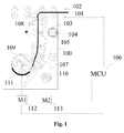
- FIG. 1 is a lateral view of an internal structure of a banknote temporary storage device 100 according to a preferred embodiment of the disclosure.
- the banknote temporary storage device 100 includes a first sensor 102, a second sensor 108, a storage roller 109, a belt standby roller 110, a coiling belt 107, a transmission path 101, a first drive motor 112, a second drive motor 113, a micro controller 106, and a signal collecting unit which includes a coded disk 103, a coded disk signal sensor 104 and a rubber wheel 105.
- the micro controller 106 controls the first drive motor 112 and the second drive motor 113.
- the first drive motor 112 drives the storage roller 109
- the second drive motor 103 drives the belt standby roller 110.
- Two ends of the coiling belt 107 are fixed to the storage roller 109 and the belt standby roller 110 respectively.
- the coiling belt 107 is wound around, and is deployed and retracted between the storage roller 109 and the belt standby roller 110.
- a banknote 111 enters the banknote temporary storage device 100 through the transmission path 101, and is stored on the storage roller via the coiling belt 107.
- the first sensor 102 is arranged at an inlet of the banknote temporary storage device, and is configured to detect whether the banknote 111 enters the banknote temporary storage device 100.
- the second sensor 108 is arranged between the first sensor and the storage roller, and is configured to detect whether the banknote leaves the banknote temporary storage device 100.
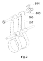
- the coded disk 103 and the rubber wheel 105 are arranged between the storage roller 109 and the belt standby roller 110 via a same rotating shaft, and the coiling belt 107 tightly engages with the rubber wheel 105 and drives the rotation of the rubber wheel 105.
- the coded disk signal sensor 104 detects the number of pulses generated by the coded disk 103. Since the coiling belt 107 tightly engages with the rubber wheel 105, the coiling belt 107 does not slip with the rubber wheel 105.
- the micro controller 106 is a control system included in the banknote temporary storage device 100.
- the control system includes a central processing unit, a calculation unit, a data storage unit and a drive control unit.
- the calculation unit is configured to calculate radiuses of the rollers and rotating speeds of the drive motors
- the data storage unit is configured to store real-time radiuses of the storage roller and the belt standby roller at an end of an operation of the banknote temporary storage device, for use when a next operation of the banknote temporary storage device is started
- the drive control unit is configured to control rotating speeds of the first drive motor and the second drive motor in real time
- the central processing unit is configured to coordinate the units of the banknote temporary storage device to control the operation of the banknote temporary storage device.
- the signal collecting unit may include a first collecting unit and a second collecting unit.
- the first collecting unit is configured to collect the number of pulses generated by the coded disk 103 and a period of time spent on the generation of the pluses when a real-time radius of the storage roller 109 is calculated
- the second collecting unit is configured to collect the number of pulses generated by the coded disk 103 and a period of time spent on the generation of the pluses when a real-time radius of the belt standby roller 110 is calculated.
- a control method for storing a banknote into a temporary storage device is described in conjunction with Figures 1 and 2 .
- the storage roller 109 retracts the coiling belt 107 actively and the belt standby roller 110 deploys the coiling belt 107 in a braking manner.
- the first drive motor 112 is started with the initial rotating speed W when the first photoelectric sensor 102 detects that the banknote 111 enters the banknote temporary storage device.
- the coded disk signal sensor 104 detects a signal of the coded disk 103.
- the micro controller 106 records the number N in of generated pulses and a period ⁇ t in of time for generating the N in pulses.
- a real-time radius R real-time V real-time /W current .
- the rotating speed of the storage roller 109 is adjusted each time when the banknote 111 enters the banknote temporary storage device 100, so that the linear speed of the coiling belt is always the target speed V target as the radius of the storage roller 109 changes.
- the belt standby roller is in a braking state, to tighten the coiling belt 107.
- a method for measuring a real-time radius r real-time of the belt standby roller 100 after the process of that the banknote 111 enters the banknote temporary storage device 100 is finished is described hereinafter.
- the method is as follows.
- the second drive motor 113 is started with a predetermined rotating speed w start such that the belt standby roller 110 retracts the coiling belt 107.
- the second drive motor stops running to prevent the banknote 111 from leaving the banknote temporary storage device 100.
- the current real-time radius R real-time of the storage roller and the current real-time radius r real-time of the belt standby roller are stored in the data storage unit, for use when a next operation of the banknote temporary storage device 100 is started.
- a principle for controlling the banknote temporary storage device 100 to deliver the banknote 111 out of the banknote temporary storage device 100 is described hereinafter.
- the belt standby roller 110 retracts the coiling belt 107 actively and the storage roller 109 retracts the coiling belt 107 in a braking manner.
- the coded disk signal sensor 104 detects a signal of the coded disk 103.
- the number n out of generated pulses and a period ⁇ t out of time for generating the n out pulses are recorded.
- the rotating speed of the storage roller 109 is adjusted each time when a banknote leaves the banknote temporary storage device 100, so that the linear speed of the coiling belt is always the target speed V target as the radius of the roller changes.
- the storage roller 109 When the banknote 111 is delivered out of the banknote temporary storage device 100, the storage roller 109 is in a braking state, to tighten the coiling belt 107.
- a method for measuring a real-time radius R real-time out of the storage roller 109 after the banknote 111 leaves the banknote temporary storage device 100 is described hereinafter.
- the first drive motor 112 is started with a predetermined rotating speed W start to drive the storage roller 109 to retract a portion of the coiling belt 107.
- W rotating speed
- a number N out of pulses generated by the coded disk 103 is recorded, and a period ⁇ t out1 of time for generating the pulses is recorded.
- the current real-time radius R real-time out of the storage roller and the current real-time radius r real-time out of the belt standby roller 110 are stored in the data storage unit, for use when a next operation of the banknote temporary storage device 100 is started.
- the banknote is delivered into the banknote temporary storage device and delivered out of the banknote temporary storage device
- the real-time radius of the storage roller or the belt standby roller can be calculated when each banknote enters or leaves the banknote temporary storage device, so that the rotating speed of the drive motor is adjusted based on the real-time radius, to control the rotating speed of the storage roller or the belt standby roller, thereby achieving a constant speed of the coiling belt.
Landscapes
- Engineering & Computer Science (AREA)
- Mechanical Engineering (AREA)
- Discharge By Other Means (AREA)
- Sheets, Magazines, And Separation Thereof (AREA)
- Conveying Record Carriers (AREA)
- Delivering By Means Of Belts And Rollers (AREA)
- Financial Or Insurance-Related Operations Such As Payment And Settlement (AREA)
Abstract
Description
- This application claims priority to Chinese patent application No.
201310661267.0 - The present disclosure relates to a financial self-service apparatus, particularly to a banknote temporary storage device storing a banknote with a roller and a coiling belt, and a control method for delivering a banknote into or out of the banknote temporary storage device.
- Presently, a common temporary storage device always uses mechanisms such as rollers and a rolling belt. The storage device includes a storage roller driven by a first drive motor, a belt standby roller driven by a second drive motor and a coiling belt with two ends fixed on the storage roller and the belt standby roller respectively, which is wound around, and is retracted and deployed between the storage roller and the belt standby roller. The first drive motor and the second drive motor are controlled to be started or stopped by a micro controller. This temporary storage device operates in a way that the rollers cooperates with the coiling belt to implement temporary storage of a banknote
- During operation of the temporary storage device, to ensure equally spaced banknotes, it is required to ensure that speeds of different portions of the coiling belt are constant and consistent while the coiling belt is constantly tightened to improve the tenseness of the coiling belt, whereby the storage capacity of the storage roller is improved. According to a principle of circular motion, a linear speed v is equal to an angular speed ω times a radius r. To keep a constant banknote delivering speed, i.e., to keep the linear speeds of the storage roller and the belt standby roller constant, as the coiling belt is deployed and retracted between the storage roller and the belt standby roller, radiuses of the storage roller and the belt standby roller continually change, therefore angular speeds of the first motor and the second motor need to be adjusted timely according to the radiuses of the storage roller and the belt standby roller.
- In a conventional method for controlling the temporary storage module, the radius increment ΔX of the storage roller is commonly estimated by using empirical values. The angular speeds of the first motor and the second motor are continuously adjusted according to the estimated radius increment ΔX of the storage roller and the determined radius increment ΔY of the belt standby roller, thereby ensuring that both linear speeds of the storage roller and the belt standby roller are constant and consistent. The radius change ΔX of the storage roller is an estimated value, and the radius change ΔY of the belt standby roller is a determined value setting according to the empirical values, therefore the existing method does not have enough accuracy, so that there is a difference between the linear speed of the storage roller and that of the belt standby roller, which causes loose of the coiling belt and even a cast of the coiling belt.
- Besides, the radius of the storage roller is also affected by the thickness of the stored banknote, thus a real-time radius of the storage roller can not be estimated accurately in the conventional technology, and therefore, an accurate angular speed can not be accurately calculated, which can not ensure a constant linear speed of the storage roller. In a case the linear speed of the storage roller has a big difference from that of the belt standby reel, it is apt to cause the following problems: 1, unequal spaces between banknotes on the storage roller, which causes a waste of the coiling belt, reduces the storage capacity of the storage roller, and can not satisfy a design requirement; and 2, loose of the coiling belt and even cast of the coiling belt, which increases a maintenance cost.
- To solve the problem of the loose or cast of the coiling belt caused by the fact that the coiling belt does not has a constant speed due to continually changed diameters of the storage roller and the belt standby roller, a banknote temporary storage device with a function of adjusting a rotating speed of a drive motor in real time is provided according to the present disclosure, which ensures a constant linear speed of the coiling belt.
- A method for storing a banknote by a banknote temporary storage device is provided according to the present disclosure, which includes steps of delivering (storing) the banknote into and delivering (releasing) the banknote out of the banknote temporary storage device, and can adjust an angular speed of a drive motor in real time when each banknote enters or leaves the banknote temporary storage device, thereby ensuring a constant linear speed..
- The banknote temporary storage device includes a storage roller driven by a first drive motor, a belt standby roller driven by a second drive motor and a coiling belt with two ends fixed on the storage roller and the belt standby roller respectively, which is wound around, and is retracted and deployed between the storage roller and the belt standby roller. The banknote temporary storage device further includes: a first sensor, arranged at an inlet of the banknote temporary storage device and configured to detect whether a banknote enters the banknote temporary storage device; a second sensor, arranged between the first sensor and the storage roller and configured to detect whether the banknote leaves the banknote temporary storage device; a signal collecting unit, which includes a coded disk, a coded disk signal sensor and a rubber wheel, where the coded disk and the rubber wheel are arranged between the storage roller and the belt standby roller via a same rotating shaft, and the coiling belt tightly engages with the rubber wheel and drives the rotation of the rubber wheel; and a control system, which includes a central processing unit, a calculation unit, a data storage unit and a drive control unit, where the calculation unit is configured to calculate radiuses of the rollers and rotating speeds of the drive motors, the data storage unit is configured to store real-time radiuses of the storage roller and the belt standby roller at an end of an operation of the banknote temporary storage device, for use when a next operation of the banknote temporary storage device is started, the drive control unit is configured to control rotating speeds of the first drive motor and the second drive motor in real time, and the central processing unit is configured to coordinate the units of the banknote temporary storage device to control the operation of the banknote temporary storage device.
- The method for storing a banknote by a banknote temporary storage device includes steps 1 to 5. Step 1 includes starting a banknote temporary storage device, reading from a data storage unit parameters recorded at an end of a last operation of the banknote temporary storage device, where the parameters include a radius Rrecord of the storage roller and a radius rrecord of the belt standby roller, and calculating a rotating speed for starting a first drive motor of the banknote temporary storage device. Step 2 includes detecting by a first photoelectric sensor whether a banknote enters the banknote temporary storage device, controlling the first drive motor to rotate at the rotating speed calculated in step 1 if the banknote enters the banknote temporary storage device, starting the signal collecting unit when the first drive motor rotates at a constant speed, detecting a coded disk signal with the coded signal sensor, recording the number N of generated pulses and a period Δt of time for generating the N pulses, calculating, with a known number M of pulses generated by the coded disk during one turn and a known diameter D of the rubber wheel which is coaxial with the coded disk and tightly engages with the coiling belt, a moving distance L of the coiling belt during the period Δt of time according to the formula L = (N/M)*πD (it is required that N is recorded when the first drive motor rotates at the constant speed, and N is smaller than 3 times M), and calculating a real-time linear speed Vreal-time of the coiling belt when each banknote enters the banknote temporary storage device according to the formula Vreal-time= L/Δt. Step 3 includes calculating, with a known current rotating speed W of the storage roller, a real-time radius Rreal-time according to the circular motion principle Rreal-time= Vreal-time/W, and calculating, with a known target speed Vtarget to which the speed of the coiling belt needs to be adjusted, a rotating speed Wadjusted to which the rotating speed of the first drive motor needs to be adjusted according to the formula Wadjusted= Vtarget/ Rreal-time, to ensure that the coiling belt uniformly moves at the target speed Vtarget when the banknote enters the banknote temporary storage device. Step 4 includes repeating steps 2 and 3, to adjust the rotating speed of the first drive motor when each banknote enters the banknote temporary storage device in real time and ensure that the coiling belt moves at the target speed Vtarget. Step 5 includes resetting the coiling belt after storing all banknotes to be stored, measuring a real-time radius r of the belt standby roller and storing a real-time radius R of the storage roller and the real-time radius r of the belt standby roller into the data storage unit, for use when a next operating of the banknote temporary storage device is started.
- Preferably, in steps 2 to 4, while the first drive motor is rotating, the second drive motor is in a braking state and the coiling belt is tightened by a load of the banknote temporary storage device and a braking torque of the second drive motor.
- Specially, the process of measuring a real-time radius r of the belt standby roller in step 5 includes: starting the second drive motor with a predetermined rotating speed w after a portion of the coiling belt is retracted by the storage roller, such that the belt standby roller retracts the coiling belt, and stopping the second drive motor when the second sensor detects a banknote, to prevent the banknote from leaving the banknote temporary storage device; during the process that the second drive motor rotates and stops rotation after reaching a constant speed, recording the number n of pulses generated by the coded disk , recording a period Δt1 of time of the process, and calculating a moving distance L1 of the coiling belt during the process that the belt standby roller rotates for the period Δt1 of time according to the formula: L1= (n/M)*πDc; calculating a real-time linear speed v of the coiling belt according to the formula: v=L1/Δt1; and calculating a real-time radius r of the belt standby roller according to the formula: r = v/w.
- The method for storing a banknote by a banknote temporary storage device further includes a method for delivering the banknote out of the banknote temporary storage device. The method for delivering a banknote out of the banknote temporary storage device includes steps 6 to 10. Step 6 includes starting the banknote temporary storage device, reading the parameters recorded in step 5, where the parameters include the radius R of the storage roller and the radius r of the belt standby roller, and calculating a rotating speed for starting the second drive motor of the paper money temporary storage device. Step 7 includes detecting by a second photoelectric sensor whether a banknote leaves the banknote temporary storage device, controlling the second drive motor to rotate at the rotating speed calculated in step 6 if the banknote leaves the banknote temporary storage device, detecting a coded disk signal generated by the coded signal sensor when the second drive motor rotates at a constant rotating speed, recording the number n1 of generated pulses and a period Δt2 of time for generating the n1 pulses, calculating, with a known number M of pulses generated by the coded disk during one turn and a known diameter D of the rubber wheel which is coaxial with the coded disk and tightly engages with the coiling belt, a moving distance L2 of the coiling belt during the period Δt2 of time according to the formula L2 = (n1/M)*πD (it is required that n1 is recorded when the first drive motor rotates at the constant speed, and since the first drive motor may stop rotation when each banknote enters the banknote temporary storage device, n1 can not have a large value and is smaller than 3 times M; and n1 is not associated with M and may be not equal to M), and calculating a real-time speed v1 of the coiling belt when each banknote leaves the banknote temporary storage device according to the formula v1= L2 / Δt2. Step 8 includes calculating, with a known current rotating speed w1 of the belt standby roller, a real-time radius r1 of the belt standby roller according to the circular motion principle r1= v1/w1, and calculating, with a known target speed Vtarget to which the speed of the coiling belt needs to be adjusted, a rotating speed Wadjusted to which the rotating speed of the second drive motor needs to be adjusted according to the formula Wadjusted= Vtarget/ r1, to ensure that the coiling belt uniformly moves at the target speed Vtarget when the banknote leaves the banknote temporary storage device. Step 9 includes repeating steps 7 and 8, to adjust the rotating speed of the second drive motor when each banknote leaves the banknote temporary storage device in real time and to ensure that the moving speed of the coiling belt is the target speed Vtarget. Step 10 includes resetting the coiling belt after all banknotes to be released leave the banknote temporary storage device, measuring the real-time radius R1 of the belt standby roller and storing the real-time radius R1 of the storage roller and the real-time radius r1 of the belt standby roller into the data storage unit, for use when a next operation of the banknote temporary storage device is started.
- Preferably, in steps 7 to 9, while the second drive motor is rotating, the first drive motor of the banknote temporary storage roller is drived in a braking state and the coiling belt is tightened by a load of the banknote temporary storage device and a braking torque of the first drive motor.
- Preferably, the process of measuring the real-time radius R1 of the storage roller in step 10 includes: starting, by the belt standby roller, the first drive motor with a predetermined rotating speed Wstart to retract a portion of the coiling belt; starting recording the number of pulses generated by the coded disk when the first drive motor reaches a constant speed, recording the number N1 of pulses generated by the coded disk and a period Δt3 of time before the second drive motor stops rotation, and calculating a moving distance L3 of the coiling belt during the process that the banknote temporary storage roller rotates for the period Δt3 of time according to the formula: L3=(N1/M)*πD; calculating the real-time linear speed V1 of the coiling belt according to the formula V1=L3/Δt3; and calculating the real-time radius R1 of the storage roller according to the formula R1=V3/Wstart.
- The banknote temporary storage device according to the present disclosure includes a signal collecting unit, and ingeniously use structures of the rubber wheel which is coaxial with the coded disk and tightly engages with the coiling belt, the coded disk and the coded disk signal sensor, so that the number of rotation turns of the rubber wheel is obtained by recording the number of rotation turns of the coded disk, the real-time speed of the coiling belt when each banknote enters or leaves the banknote temporary storage roller is calculated, the real-time radius of the storage roller or the belt standby roller is obtained, and the angular speed of the drive motor can be adjusted according to the real-time radius, thereby ensuring that the coiling belt uniformly moves at the target speed.
- The method for storing a banknote by a banknote temporary storage device according to the present disclosure includes steps of delivering the banknote into and out of the banknote temporary storage device. The real-time radius of the storage roller or the belt standby roller is calculated when each banknote enters or leaves the banknote temporary storage device, thereby adjusting a rotating speed of a drive motor in real time based on the real-time radius, to control a rotating speed of the storage roller or the belt standby roller and thereby achieving a constant linear speed of the coiling belt.
-
-
Figure 1 is a lateral view of a banknote temporary storage device according to a preferred embodiment of the disclosure; and -
Figure 2 is a stereogram of a signal collecting unit of a banknote temporary storage device. - To further illustrate the banknote temporary storage device according to the present disclosure, the embodiments of the disclosure are described in detail in conjunction with drawings.
-
Figure 1 is a lateral view of an internal structure of a banknotetemporary storage device 100 according to a preferred embodiment of the disclosure. The banknotetemporary storage device 100 includes afirst sensor 102, asecond sensor 108, astorage roller 109, abelt standby roller 110, acoiling belt 107, atransmission path 101, afirst drive motor 112, asecond drive motor 113, amicro controller 106, and a signal collecting unit which includes a codeddisk 103, a codeddisk signal sensor 104 and arubber wheel 105. - The
micro controller 106 controls thefirst drive motor 112 and thesecond drive motor 113. Thefirst drive motor 112 drives thestorage roller 109, and thesecond drive motor 103 drives thebelt standby roller 110. Two ends of thecoiling belt 107 are fixed to thestorage roller 109 and thebelt standby roller 110 respectively. Thecoiling belt 107 is wound around, and is deployed and retracted between thestorage roller 109 and thebelt standby roller 110. Abanknote 111 enters the banknotetemporary storage device 100 through thetransmission path 101, and is stored on the storage roller via thecoiling belt 107. Thefirst sensor 102 is arranged at an inlet of the banknote temporary storage device, and is configured to detect whether thebanknote 111 enters the banknotetemporary storage device 100. Thesecond sensor 108 is arranged between the first sensor and the storage roller, and is configured to detect whether the banknote leaves the banknotetemporary storage device 100. - As shown in
Figure 2 , the codeddisk 103 and therubber wheel 105 are arranged between thestorage roller 109 and thebelt standby roller 110 via a same rotating shaft, and thecoiling belt 107 tightly engages with therubber wheel 105 and drives the rotation of therubber wheel 105. When thecoiling belt 107 drives the rotation of therubber wheel 105, the codeddisk signal sensor 104 detects the number of pulses generated by the codeddisk 103. Since thecoiling belt 107 tightly engages with therubber wheel 105, thecoiling belt 107 does not slip with therubber wheel 105. - The
micro controller 106 is a control system included in the banknotetemporary storage device 100. The control system includes a central processing unit, a calculation unit, a data storage unit and a drive control unit. The calculation unit is configured to calculate radiuses of the rollers and rotating speeds of the drive motors, the data storage unit is configured to store real-time radiuses of the storage roller and the belt standby roller at an end of an operation of the banknote temporary storage device, for use when a next operation of the banknote temporary storage device is started, the drive control unit is configured to control rotating speeds of the first drive motor and the second drive motor in real time, and the central processing unit is configured to coordinate the units of the banknote temporary storage device to control the operation of the banknote temporary storage device. - Preferably, the signal collecting unit may include a first collecting unit and a second collecting unit. The first collecting unit is configured to collect the number of pulses generated by the coded
disk 103 and a period of time spent on the generation of the pluses when a real-time radius of thestorage roller 109 is calculated, and the second collecting unit is configured to collect the number of pulses generated by the codeddisk 103 and a period of time spent on the generation of the pluses when a real-time radius of thebelt standby roller 110 is calculated. - A control method for storing a banknote into a temporary storage device is described in conjunction with
Figures 1 and2 . - When a
banknote 111 is deliver into the banknotetemporary storage device 100, thestorage roller 109 retracts thecoiling belt 107 actively and thebelt standby roller 110 deploys thecoiling belt 107 in a braking manner. - Before the banknote
temporary storage device 100 operates, themicro controller 106 reads a current initial radius Rrecord of thestorage roller 109 from the data storage unit, and calculates an initial rotating speed Winitial of the two rollers according a target speed Vtarget:
- The
first drive motor 112 is started with the initial rotating speed W when the firstphotoelectric sensor 102 detects that thebanknote 111 enters the banknote temporary storage device. - When the
first drive motor 112 operates at a constant speed, the codeddisk signal sensor 104 detects a signal of the codeddisk 103. Themicro controller 106 records the number Nin of generated pulses and a period Δtin of time for generating the Nin pulses. With a known constant number M of pulses generated by the codeddisk 103 during one turn and a known constant diameter D of therubber wheel 105, a moving distance Lin of the coilingbelt 107 during the period Δtin of time can be calculated according to the formula: Lin = (Nin/M)*πD. - Thus, a real-time linear speed Vreal-time of the coiling
belt 107 can be calculated when eachbanknote 111 enters the banknote temporary storage device 100:
- With a known current rotating speed Wcurrent of the storage roller 109 (when the first banknote enters the banknote
temporary storage device 100, the speed of thestorage roller 109 is an initial speed Winitial), a real-time radius Rreal-time can be calculated according to the formula: Rreal-time =Vreal-time/Wcurrent. - With a known target speed Vtarget to be adjusted, a rotating speed Wadjusted to which the speed of the storage roller needs to be adjusted can be calculated according to the following formula:

- With the method above, the rotating speed of the
storage roller 109 is adjusted each time when thebanknote 111 enters the banknotetemporary storage device 100, so that the linear speed of the coiling belt is always the target speed Vtarget as the radius of thestorage roller 109 changes. - During the process that the
banknote 111 enters the banknotetemporary storage device 100, the belt standby roller is in a braking state, to tighten the coilingbelt 107. - A method for measuring a real-time radius rreal-time of the
belt standby roller 100 after the process of that thebanknote 111 enters the banknotetemporary storage device 100 is finished is described hereinafter. The method is as follows. - After the
storage roller 109 retracts a portion of the coilingbelt 107, thesecond drive motor 113 is started with a predetermined rotating speed wstart such that thebelt standby roller 110 retracts the coilingbelt 107. When the second sensor detects thebanknote 111, the second drive motor stops running to prevent thebanknote 111 from leaving the banknotetemporary storage device 100. - During the process that the
second drive motor 113 rotates and stops rotation after reaching a constant speed, the number nin of pulses generated by the coded disk is recorded, , and a period Δtin1 of time for the process is recorded, and a moving distance Lin1 of the coilingbelt 107 during the process that that thebelt standby roller 110 rotates for the period Δtin1 of time can be calculated according to the formula: Lin1 = (nm/M)*πD;
a real-time linear speed Vreal-time of the coiling belt is further calculated according to the formula: Vreal-time=Lin1/Δtin1;
and a real-time radius rreal-time of the belt standby roller is further calculated according to the formula: rreal-time = Vreal-time/wstart. - When the banknote
temporary storage device 100 stops operation, the current real-time radius Rreal-time of the storage roller and the current real-time radius rreal-time of the belt standby roller are stored in the data storage unit, for use when a next operation of the banknotetemporary storage device 100 is started. - A principle for controlling the banknote
temporary storage device 100 to deliver thebanknote 111 out of the banknotetemporary storage device 100 is described hereinafter. - When the
banknote 111 is delivered out of the banknotetemporary storage device 100, thebelt standby roller 110 retracts the coilingbelt 107 actively and thestorage roller 109 retracts the coilingbelt 107 in a braking manner. - Before the banknote
temporary storage device 100 operates, themicro controller 106 reads a current initial radius rrecord of thebelt standby roller 110 from the data storage unit, and calculates an initial rotating speed winitial of the belt standby roller according to the target speed Vtarget: winitial= Vtarget / rrecord. - During the process that the
banknote 111 is delivered out of the banknotetemporary storage device 100, when thesecond drive motor 113 reaches a constant speed, the codeddisk signal sensor 104 detects a signal of the codeddisk 103. The number nout of generated pulses and a period Δtout of time for generating the nout pulses are recorded. With the known number M of pulses generated by the codeddisk 103 during one turn and a known diameter D of therubber wheel 105 which is coaxial with thecoded disk 103 and tightly engages with the coilingbelt 107, a moving distance Lout of the coilingbelt 107 during the period Δtout of time can be calculated according to the formula: Lout = (nout /M)*πD. - Thus, a real-time linear speed Vreal-time out of the coiling
belt 107 can be calculated when thebanknote 111 leaves the banknotetemporary storage device 100 according to the formula:
- With a known current rotating speed wcurrent of the belt standby roller 110 (when the first banknote enters the banknote
temporary storage device 100, the speed of thestorage roller 109 is an initial speed Winitial), a real-time radius rreal-time out can be calculated according to the formula: rreal-time out = vreal-time out / wcurrent. - With the known target speed Vtarget to which the speed of the belt standby roller needs to be adjusted, a rotating speed wadjusted to which the rotating speed of the
belt standby roller 110 needs to be adjusted can be calculated according to the following formula:
- With the method above, the rotating speed of the
storage roller 109 is adjusted each time when a banknote leaves the banknotetemporary storage device 100, so that the linear speed of the coiling belt is always the target speed Vtarget as the radius of the roller changes. - When the
banknote 111 is delivered out of the banknotetemporary storage device 100, thestorage roller 109 is in a braking state, to tighten the coilingbelt 107. - A method for measuring a real-time radius Rreal-time out of the
storage roller 109 after thebanknote 111 leaves the banknotetemporary storage device 100 is described hereinafter. - The
first drive motor 112 is started with a predetermined rotating speed Wstart to drive thestorage roller 109 to retract a portion of the coilingbelt 107. When the first drive motor reaches a constant speed, a number Nout of pulses generated by the codeddisk 103 is recorded, and a period Δtout1 of time for generating the pulses is recorded. A moving distance Lout1 of the coilingbelt 107 during the period Δtout1 of time that thestorage roller 109 rotates can be calculated according to the formula: Lout1 = (Nout /M)*πD; - A real-time linear speed Vreal-time out of the coiling
belt 107 is further calculated according to the formula: Vreal-time out = Lout1 /Δtout1. - A real-time radius Rreal-time out of the
storage roller 109 is further calculated according to the formula: Rreal-time out = Vreal-time out /Wstart. - When the banknote
temporary storage device 100 stops operation, the current real-time radius Rreal-time out of the storage roller and the current real-time radius rreal-time out of thebelt standby roller 110 are stored in the data storage unit, for use when a next operation of the banknotetemporary storage device 100 is started. - In the method for storing a banknote by a banknote temporary storage device according to the embodiment, the banknote is delivered into the banknote temporary storage device and delivered out of the banknote temporary storage device, the real-time radius of the storage roller or the belt standby roller can be calculated when each banknote enters or leaves the banknote temporary storage device, so that the rotating speed of the drive motor is adjusted based on the real-time radius, to control the rotating speed of the storage roller or the belt standby roller, thereby achieving a constant speed of the coiling belt.
- The foregoing embodiments are only preferred embodiments of the disclosure. It should be noted that the preferred embodiments according to the disclosure are not intended to limit the disclosure. The scope of the disclosure is subject to the scope of the claims. Those of skills in the art may make some variations and improvements on the technical solutions of the disclosure without departing from the spirit and scope of the technical solutions. All simple variations and improvements made without departing from spirit and scope of the technical solutions of the disclosure fall in the scope of the technical solutions of the disclosure.
Claims (7)
- A banknote temporary storage device, comprising a storage roller driven by a first drive motor, a belt standby roller driven by a second drive motor and a coiling belt with two ends fixed on the storage roller and the belt standby roller respectively, the coiling belt being wound around the storage roller and the belt standby roller, and being retracted and deployed between the storage roller and the belt standby roller, wherein,
the banknote temporary storage device further comprises:a first sensor, arranged at an inlet of the banknote temporary storage device and configured to detect whether a banknote enters the banknote temporary storage device;a second sensor, arranged between the first sensor and the storage roller and configured to detect whether the banknote leaves the banknote temporary storage device;a signal collecting unit, comprising a coded disk, a coded disk signal sensor and a rubber wheel, wherein the coded disk and the rubber wheel are arranged between the storage roller and the belt standby roller via a same rotating shaft and the coiling belt tightly engages with the rubber wheel and drives the rotation of the rubber wheel; anda control system, comprising a central processing unit, a calculation unit, a data storage unit and a drive control unit, wherein the calculation unit is configured to calculate radiuses of the rollers and rotating speeds of the drive motors, the data storage unit is configured to store real-time radiuses of the storage roller and the belt standby roller at an end of an operation of the banknote temporary storage device, for use when a next operation of the banknote temporary storage device is started, the drive control unit is configured to control rotating speeds of the first drive motor and the second drive motor in a real time, and the central processing unit is configured to coordinate the units of the banknote temporary storage device to control the operation of the banknote temporary storage device. - A method for storing a banknote by a banknote temporary storage device, comprising:step 1 which comprises starting a banknote temporary storage device, reading, from a data storage unit, parameters recorded at an end of a last operating of the banknote temporary storage device, wherein the parameters comprises a radius Rrecord of the storage roller and a radius rrecord of the belt standby roller, and calculating a rotating speed for starting a first drive motor of the banknote temporary storage device;step 2 which comprises detecting by a first photoelectric sensor whether a banknote enters the banknote temporary storage device, controlling the first drive motor to rotate at the rotating speed calculated in step 1 if the banknote enters the banknote temporary storage device, starting the signal collecting unit when the first drive motor rotates at a constant speed, detecting a coded disk signal with the coded signal sensor, recording the number N of generated pulses and a period Δt of time for generating the N pulses,calculating, with a known number M of pulses generated by the coded disk during one turn and a known diameter D of the rubber wheel which is coaxial with the coded disk and tightly engages with the coiling belt, a moving distance L of the coiling belt during the period Δt of time according to the formula L = (N/M)*πD (it is required that N is recorded when the first drive motor rotates at the constant speed, and N is smaller than 3 times M), andcalculating a real-time linear speed Vreal-time of the coiling belt when each banknote enters the banknote temporary storage device according to the formula Vreal-time= L/Δt;step 3 which comprises calculating, with a known current rotating speed W of the storage roller, a real-time radius Rreal-time according to the circular motion principle Rreal-time= Vreal-time/W, and calculating, with a known target speed Vtarget to which the speed of the coiling belt needs to be adjusted, a rotating speed Wadjusted to which the rotating speed of the first drive motor needs to be adjusted according to the formula Wadjusted= Vtarget/ Rreal-time, to ensure that the coiling belt uniformly moves at the target speed Vtarget when the banknote enters the banknote temporary storage device;step 4 which comprises repeating steps 2 and 3, to adjust the rotating speed of the first drive motor when each banknote enters the banknote temporary storage device in real time and ensure that the coiling belt moves at the target speed Vtarget; andstep 5 which comprises resetting the coiling belt after storing all banknotes to be stored, measuring a real-time radius r of the belt standby roller and storing a real-time radius R of the storage roller and the real-time radius r of the belt standby roller into the data storage unit, for use when a next operating of the banknote temporary storage device is started.
- The method for storing a banknote by a banknote temporary storage device according to claim 2, wherein, in steps 2 to 4, while the first drive motor is rotating, the second drive motor is in a braking state and the coiling belt is tightened by a load of the banknote temporary storage device and a braking torque of the second drive motor.
- The method for storing a banknote by a banknote temporary storage device according to claim 3, wherein, the process of measuring a real-time radius r of the belt standby roller in step 5 comprises:starting the second drive motor with a predetermined rotating speed w after a portion of the coiling belt is retracted by the storage roller, such that the belt standby roller retracts the coiling belt, and stopping the second drive motor when the second sensor detects a banknote, to prevent the banknote from leaving the banknote temporary storage device;during the process that the second drive motor rotates and stops rotation after reaching a constant speed, recording the number n of pulses generated by the coded disk, recording a period Δt1 of time of the process, and calculating a moving distance L1 of the coiling belt during the process that the belt standby roller rotates for the period Δt1 of time according to the formula: L1= (n/M)*πD;calculating a real-time linear speed v of the coiling belt according to the formula: v=L1/Δt1; andcalculating a real-time radius r of the belt standby roller according to the formula: r = v/w.
- The method for storing a banknote by a banknote temporary storage device according to claim 2, further comprising a method for delivering the banknote out of the banknote temporary storage device, wherein the method for delivering the banknote out of the banknote temporary storage device comprises:step 6 which comprises starting the banknote temporary storage device, reading the parameters recorded in step 5, wherein the parameters comprise the radius R of the storage roller and the radius r of the belt standby roller, and calculating a rotating speed for starting the second drive motor of the paper money temporary storage device;step 7 which comprises detecting by a second photoelectric sensor whether a banknote leaves the banknote temporary storage device, controlling the second drive motor to rotate at the rotating speed calculated in step 6 if the banknote leaves the banknote temporary storage device, detecting a coded disk signal generated by the coded signal sensor when the second drive motor rotates at a constant rotating speed, recording the number n1 of generated pulses and a period Δt2 of time for generating the n1 pulses, calculating, with a known number M of pulses generated by the coded disk during one turn and a known diameter D of the rubber wheel which is coaxial with the coded disk and tightly engages with the coiling belt, a moving distance L2 of the coiling belt during the period Δt2 of time according to the formula:L2 = (n1/M)*πD, (it is required that n1 is recorded when the first drive motor rotates at the constant speed, and since the first drive motor may stop rotation when each banknote enters the banknote temporary storage device, n1 can not have a large value and is smaller than 3 times M; and n1 is not associated with M and may be not equal to M), andcalculating a real-time speed v1 of the coiling belt when each banknote leaves the banknote temporary storage device according to the formula v1= L2/Δt2;step 8 which comprises calculating, with a known current rotating speed w1 of the belt standby roller, a real-time radius r1 of the belt standby roller according to the circular motion principle r1= v1/w1, and calculating, with a known target speed Vtarget to which the speed of the coiling belt needs to be adjusted, a rotating speed Wadjusted to which the rotating speed of the second drive motor needs to be adjusted according to the formula Wadjusted= Vtarget/ r1, to ensure that the coiling belt uniformly moves at the target speed Vtarget when the banknote leaves the banknote temporary storage device;step 9 which comprises repeating steps 7 and 8, to adjust the rotating speed of the second drive motor when each banknote leaves the banknote temporary storage device in real time and to ensure that the moving speed of the coiling belt is the target speed Vtarget; andstep 10 which comprises resetting the coiling belt after all banknotes to be released leave the banknote temporary storage device, measuring the real-time radius R1 of the belt standby roller and storing the real-time radius R1 of the storage roller and the real-time radius r1 of the belt standby roller into the data storage unit, for use when a next operation of the banknote temporary storage device is started.
- The method for storing a banknote by a banknote temporary storage device according to claim 5, wherein, in steps 7 to 9, while the second drive motor is rotating, the first drive motor is drived in a braking state and the coiling belt is tightened by a load of the banknote temporary storage device and a braking torque of the first drive motor.
- The method for storing a banknote by a banknote temporary storage device according to claim 6, wherein, the process of measuring a real-time radius R1 of the storage roller in step 10 comprises:starting, by the belt standby roller, the first drive motor with a predetermined rotating speed Wstart to retract a portion of the coiling belt; starting recording the number of pulses generated by the coded disk when the first drive motor reaches a constant speed, recording the number N1 of pulses generated by the coded disk and a period Δt3 of time before the second drive motor stops rotation, and calculating a moving distance L3 of the coiling belt during the process that the banknote temporary storage roller rotates for the period Δt3 of time according to the formula: L3=(N1/M)*πD;calculating the real-time linear speed V1 of the coiling belt according to the formula V1 = L3/Δt3; andcalculating the real-time radius R1 of the storage roller according to the formula R1 = V3/Wstart.
Applications Claiming Priority (2)
| Application Number | Priority Date | Filing Date | Title |
|---|---|---|---|
| CN201310661267.0A CN103617675B (en) | 2013-12-06 | 2013-12-06 | The method of Paper money temporary storage device and storage bank note thereof |
| PCT/CN2014/089380 WO2015081770A1 (en) | 2013-12-06 | 2014-10-24 | Paper money temporary storage device and paper money storage method therefor |
Publications (3)
| Publication Number | Publication Date |
|---|---|
| EP3079128A1 true EP3079128A1 (en) | 2016-10-12 |
| EP3079128A4 EP3079128A4 (en) | 2017-04-19 |
| EP3079128B1 EP3079128B1 (en) | 2018-06-06 |
Family
ID=50168379
Family Applications (1)
| Application Number | Title | Priority Date | Filing Date |
|---|---|---|---|
| EP14866849.4A Active EP3079128B1 (en) | 2013-12-06 | 2014-10-24 | Paper money temporary storage device and paper money storage method therefor |
Country Status (7)
| Country | Link |
|---|---|
| US (1) | US9670024B2 (en) |
| EP (1) | EP3079128B1 (en) |
| CN (1) | CN103617675B (en) |
| AU (1) | AU2014359947B9 (en) |
| CL (1) | CL2016001337A1 (en) |
| WO (1) | WO2015081770A1 (en) |
| ZA (1) | ZA201604123B (en) |
Families Citing this family (10)
| Publication number | Priority date | Publication date | Assignee | Title |
|---|---|---|---|---|
| CN103617675B (en) | 2013-12-06 | 2016-04-20 | 广州广电运通金融电子股份有限公司 | The method of Paper money temporary storage device and storage bank note thereof |
| CN103942874A (en) * | 2014-04-10 | 2014-07-23 | 尤新革 | Money counting and money detecting machine with speed adjusted through software |
| CN104036587B (en) * | 2014-06-30 | 2016-05-11 | 广州广电运通金融电子股份有限公司 | A kind of portable drum-type paper money case and a kind of ATM |
| CN104609245B (en) | 2014-12-15 | 2017-01-25 | 广州广电运通金融电子股份有限公司 | Temporary paper money storage device and control method thereof |
| CN105731169B (en) * | 2015-07-22 | 2019-04-26 | 深圳怡化电脑股份有限公司 | The control method and control device of paper money temporary storage module |
| CN107886618A (en) * | 2017-12-01 | 2018-04-06 | 深圳怡化电脑股份有限公司 | A kind of paper money temporary control system, method and its device |
| CN108257329A (en) * | 2017-12-29 | 2018-07-06 | 深圳怡化电脑股份有限公司 | Motor speed control method, motor speed control device and electronic equipment |
| CN108230546B (en) * | 2018-01-10 | 2020-11-17 | 深圳怡化电脑股份有限公司 | Banknote thickness abnormality detection method and device, terminal device and storage medium |
| CN112749573B (en) * | 2020-12-29 | 2023-04-28 | 杭州海康机器人股份有限公司 | Bar code matching method, device, electronic equipment and bar code matching system |
| CN113706796B (en) * | 2021-10-27 | 2022-03-08 | 恒银金融科技股份有限公司 | Temporary storage module on deposit core and deposit core |
Family Cites Families (11)
| Publication number | Priority date | Publication date | Assignee | Title |
|---|---|---|---|---|
| US4513898A (en) | 1982-03-22 | 1985-04-30 | Centronics Data Computer Corp. | Web loop control apparatus and method |
| JP3534966B2 (en) * | 1996-12-25 | 2004-06-07 | グローリー工業株式会社 | Tape speed control device for tape-type bill storage and feeding device |
| JP3760375B2 (en) * | 2000-12-22 | 2006-03-29 | 日立オムロンターミナルソリューションズ株式会社 | Banknote handling equipment |
| JP4130887B2 (en) * | 2002-10-03 | 2008-08-06 | 日立オムロンターミナルソリューションズ株式会社 | Bill storage and discharge device and bill transport device |
| JP4058322B2 (en) | 2002-10-07 | 2008-03-05 | 株式会社ルネサステクノロジ | Memory card |
| US8561888B1 (en) * | 2005-08-29 | 2013-10-22 | Diebold, Incorporated | Check cashing banking system controlled responsive to data bearing records |
| GB0525676D0 (en) * | 2005-12-16 | 2006-01-25 | Rue De Int Ltd | Roll storage module and method for its operation |
| CN102431813B (en) | 2011-09-08 | 2015-04-15 | 广州广电运通金融电子股份有限公司 | Sheet article separating mechanism and control method and control system thereof |
| CN102930638B (en) | 2012-11-15 | 2014-12-31 | 广州广电运通金融电子股份有限公司 | Paper money temporary storage module and reel rotating speed control method thereof |
| CN103395654B (en) | 2013-07-12 | 2016-03-02 | 广州广电运通金融电子股份有限公司 | A kind of bank note storage means and equipment |
| CN103617675B (en) | 2013-12-06 | 2016-04-20 | 广州广电运通金融电子股份有限公司 | The method of Paper money temporary storage device and storage bank note thereof |
-
2013
- 2013-12-06 CN CN201310661267.0A patent/CN103617675B/en active Active
-
2014
- 2014-10-24 EP EP14866849.4A patent/EP3079128B1/en active Active
- 2014-10-24 AU AU2014359947A patent/AU2014359947B9/en not_active Ceased
- 2014-10-24 US US15/100,756 patent/US9670024B2/en not_active Expired - Fee Related
- 2014-10-24 WO PCT/CN2014/089380 patent/WO2015081770A1/en not_active Ceased
-
2016
- 2016-06-01 CL CL2016001337A patent/CL2016001337A1/en unknown
- 2016-06-17 ZA ZA2016/04123A patent/ZA201604123B/en unknown
Also Published As
| Publication number | Publication date |
|---|---|
| ZA201604123B (en) | 2017-08-30 |
| CN103617675A (en) | 2014-03-05 |
| CL2016001337A1 (en) | 2017-03-31 |
| AU2014359947B9 (en) | 2017-11-30 |
| WO2015081770A1 (en) | 2015-06-11 |
| AU2014359947B2 (en) | 2017-06-22 |
| EP3079128A4 (en) | 2017-04-19 |
| US9670024B2 (en) | 2017-06-06 |
| US20160304307A1 (en) | 2016-10-20 |
| CN103617675B (en) | 2016-04-20 |
| AU2014359947A1 (en) | 2016-06-16 |
| EP3079128B1 (en) | 2018-06-06 |
Similar Documents
| Publication | Publication Date | Title |
|---|---|---|
| EP3079128B1 (en) | Paper money temporary storage device and paper money storage method therefor | |
| CN102930638B (en) | Paper money temporary storage module and reel rotating speed control method thereof | |
| US6669136B2 (en) | Paper money handling device | |
| EP1409388B1 (en) | Method for controlling a web accumulator and web accumulator for storing sheetlike objects | |
| CN105499280A (en) | Precise strip steel tail positioning control method for strip steel coiler | |
| CN113800303B (en) | A tension control device and control method for organic coating equipment | |
| CN104368606B (en) | Rolling control device, control method for rolling | |
| CN102951485A (en) | Media conveyance device, printing device, and media conveyance method | |
| CN103676990B (en) | Paper money temporary storage module and its drum speed control method and ATM | |
| CN103395654B (en) | A kind of bank note storage means and equipment | |
| EP2807099B1 (en) | Methods and systems for dispensing | |
| US7654485B2 (en) | Banknote store | |
| CN114212619B (en) | Method and device for determining roll diameter, storage medium and winding and unwinding equipment | |
| JP2006327199A (en) | Method and device for winding ribbon | |
| CN211254656U (en) | Rolling inspection machine with oscillation adjustment mechanism | |
| CN105731169B (en) | The control method and control device of paper money temporary storage module | |
| CN106672705A (en) | Yarn winding coil counting device and counting method thereof | |
| CA2325407A1 (en) | Reel for a thin metal strip | |
| US12492092B2 (en) | Media collecting | |
| RU2256518C1 (en) | Strip tension regulating method in coiler of reversing mill for coil rolling of strip | |
| CN203199742U (en) | Winding plate for band saw blade material winding device | |
| JPS60227923A (en) | Tail end stop position determining method of steel band of winder | |
| CN104107846A (en) | Roll-in device and roll-in method of band saw blade material | |
| JPH09276917A (en) | Rolling mill operation control device | |
| JPS61150954A (en) | Unwinder automatic stop control system by detecting the number of remaining turns |
Legal Events
| Date | Code | Title | Description |
|---|---|---|---|
| PUAI | Public reference made under article 153(3) epc to a published international application that has entered the european phase |
Free format text: ORIGINAL CODE: 0009012 |
|
| 17P | Request for examination filed |
Effective date: 20160615 |
|
| AK | Designated contracting states |
Kind code of ref document: A1 Designated state(s): AL AT BE BG CH CY CZ DE DK EE ES FI FR GB GR HR HU IE IS IT LI LT LU LV MC MK MT NL NO PL PT RO RS SE SI SK SM TR |
|
| AX | Request for extension of the european patent |
Extension state: BA ME |
|
| DAX | Request for extension of the european patent (deleted) | ||
| A4 | Supplementary search report drawn up and despatched |
Effective date: 20170320 |
|
| RIC1 | Information provided on ipc code assigned before grant |
Ipc: G07D 11/00 20060101AFI20170314BHEP Ipc: B65H 29/00 20060101ALI20170314BHEP Ipc: B65H 43/00 20060101ALI20170314BHEP |
|
| GRAP | Despatch of communication of intention to grant a patent |
Free format text: ORIGINAL CODE: EPIDOSNIGR1 |
|
| RIC1 | Information provided on ipc code assigned before grant |
Ipc: G07D 11/00 20060101AFI20171129BHEP Ipc: B65H 43/00 20060101ALI20171129BHEP Ipc: B65H 29/00 20060101ALI20171129BHEP |
|
| INTG | Intention to grant announced |
Effective date: 20180103 |
|
| GRAS | Grant fee paid |
Free format text: ORIGINAL CODE: EPIDOSNIGR3 |
|
| GRAA | (expected) grant |
Free format text: ORIGINAL CODE: 0009210 |
|
| AK | Designated contracting states |
Kind code of ref document: B1 Designated state(s): AL AT BE BG CH CY CZ DE DK EE ES FI FR GB GR HR HU IE IS IT LI LT LU LV MC MK MT NL NO PL PT RO RS SE SI SK SM TR |
|
| REG | Reference to a national code |
Ref country code: GB Ref legal event code: FG4D |
|
| REG | Reference to a national code |
Ref country code: CH Ref legal event code: EP Ref country code: AT Ref legal event code: REF Ref document number: 1006906 Country of ref document: AT Kind code of ref document: T Effective date: 20180615 |
|
| REG | Reference to a national code |
Ref country code: IE Ref legal event code: FG4D |
|
| REG | Reference to a national code |
Ref country code: DE Ref legal event code: R096 Ref document number: 602014026822 Country of ref document: DE |
|
| REG | Reference to a national code |
Ref country code: NL Ref legal event code: MP Effective date: 20180606 |
|
| REG | Reference to a national code |
Ref country code: LT Ref legal event code: MG4D |
|
| REG | Reference to a national code |
Ref country code: FR Ref legal event code: PLFP Year of fee payment: 5 |
|
| PG25 | Lapsed in a contracting state [announced via postgrant information from national office to epo] |
Ref country code: BG Free format text: LAPSE BECAUSE OF FAILURE TO SUBMIT A TRANSLATION OF THE DESCRIPTION OR TO PAY THE FEE WITHIN THE PRESCRIBED TIME-LIMIT Effective date: 20180906 Ref country code: NO Free format text: LAPSE BECAUSE OF FAILURE TO SUBMIT A TRANSLATION OF THE DESCRIPTION OR TO PAY THE FEE WITHIN THE PRESCRIBED TIME-LIMIT Effective date: 20180906 Ref country code: FI Free format text: LAPSE BECAUSE OF FAILURE TO SUBMIT A TRANSLATION OF THE DESCRIPTION OR TO PAY THE FEE WITHIN THE PRESCRIBED TIME-LIMIT Effective date: 20180606 Ref country code: CY Free format text: LAPSE BECAUSE OF FAILURE TO SUBMIT A TRANSLATION OF THE DESCRIPTION OR TO PAY THE FEE WITHIN THE PRESCRIBED TIME-LIMIT Effective date: 20180606 Ref country code: ES Free format text: LAPSE BECAUSE OF FAILURE TO SUBMIT A TRANSLATION OF THE DESCRIPTION OR TO PAY THE FEE WITHIN THE PRESCRIBED TIME-LIMIT Effective date: 20180606 Ref country code: SE Free format text: LAPSE BECAUSE OF FAILURE TO SUBMIT A TRANSLATION OF THE DESCRIPTION OR TO PAY THE FEE WITHIN THE PRESCRIBED TIME-LIMIT Effective date: 20180606 Ref country code: LT Free format text: LAPSE BECAUSE OF FAILURE TO SUBMIT A TRANSLATION OF THE DESCRIPTION OR TO PAY THE FEE WITHIN THE PRESCRIBED TIME-LIMIT Effective date: 20180606 |
|
| PG25 | Lapsed in a contracting state [announced via postgrant information from national office to epo] |
Ref country code: LV Free format text: LAPSE BECAUSE OF FAILURE TO SUBMIT A TRANSLATION OF THE DESCRIPTION OR TO PAY THE FEE WITHIN THE PRESCRIBED TIME-LIMIT Effective date: 20180606 Ref country code: RS Free format text: LAPSE BECAUSE OF FAILURE TO SUBMIT A TRANSLATION OF THE DESCRIPTION OR TO PAY THE FEE WITHIN THE PRESCRIBED TIME-LIMIT Effective date: 20180606 Ref country code: HR Free format text: LAPSE BECAUSE OF FAILURE TO SUBMIT A TRANSLATION OF THE DESCRIPTION OR TO PAY THE FEE WITHIN THE PRESCRIBED TIME-LIMIT Effective date: 20180606 Ref country code: GR Free format text: LAPSE BECAUSE OF FAILURE TO SUBMIT A TRANSLATION OF THE DESCRIPTION OR TO PAY THE FEE WITHIN THE PRESCRIBED TIME-LIMIT Effective date: 20180907 |
|
| PG25 | Lapsed in a contracting state [announced via postgrant information from national office to epo] |
Ref country code: NL Free format text: LAPSE BECAUSE OF FAILURE TO SUBMIT A TRANSLATION OF THE DESCRIPTION OR TO PAY THE FEE WITHIN THE PRESCRIBED TIME-LIMIT Effective date: 20180606 |
|
| PG25 | Lapsed in a contracting state [announced via postgrant information from national office to epo] |
Ref country code: EE Free format text: LAPSE BECAUSE OF FAILURE TO SUBMIT A TRANSLATION OF THE DESCRIPTION OR TO PAY THE FEE WITHIN THE PRESCRIBED TIME-LIMIT Effective date: 20180606 Ref country code: PL Free format text: LAPSE BECAUSE OF FAILURE TO SUBMIT A TRANSLATION OF THE DESCRIPTION OR TO PAY THE FEE WITHIN THE PRESCRIBED TIME-LIMIT Effective date: 20180606 Ref country code: IS Free format text: LAPSE BECAUSE OF FAILURE TO SUBMIT A TRANSLATION OF THE DESCRIPTION OR TO PAY THE FEE WITHIN THE PRESCRIBED TIME-LIMIT Effective date: 20181006 Ref country code: RO Free format text: LAPSE BECAUSE OF FAILURE TO SUBMIT A TRANSLATION OF THE DESCRIPTION OR TO PAY THE FEE WITHIN THE PRESCRIBED TIME-LIMIT Effective date: 20180606 Ref country code: CZ Free format text: LAPSE BECAUSE OF FAILURE TO SUBMIT A TRANSLATION OF THE DESCRIPTION OR TO PAY THE FEE WITHIN THE PRESCRIBED TIME-LIMIT Effective date: 20180606 Ref country code: SK Free format text: LAPSE BECAUSE OF FAILURE TO SUBMIT A TRANSLATION OF THE DESCRIPTION OR TO PAY THE FEE WITHIN THE PRESCRIBED TIME-LIMIT Effective date: 20180606 |
|
| PG25 | Lapsed in a contracting state [announced via postgrant information from national office to epo] |
Ref country code: SM Free format text: LAPSE BECAUSE OF FAILURE TO SUBMIT A TRANSLATION OF THE DESCRIPTION OR TO PAY THE FEE WITHIN THE PRESCRIBED TIME-LIMIT Effective date: 20180606 |
|
| REG | Reference to a national code |
Ref country code: DE Ref legal event code: R097 Ref document number: 602014026822 Country of ref document: DE |
|
| PLBE | No opposition filed within time limit |
Free format text: ORIGINAL CODE: 0009261 |
|
| STAA | Information on the status of an ep patent application or granted ep patent |
Free format text: STATUS: NO OPPOSITION FILED WITHIN TIME LIMIT |
|
| 26N | No opposition filed |
Effective date: 20190307 |
|
| PG25 | Lapsed in a contracting state [announced via postgrant information from national office to epo] |
Ref country code: SI Free format text: LAPSE BECAUSE OF FAILURE TO SUBMIT A TRANSLATION OF THE DESCRIPTION OR TO PAY THE FEE WITHIN THE PRESCRIBED TIME-LIMIT Effective date: 20180606 Ref country code: DK Free format text: LAPSE BECAUSE OF FAILURE TO SUBMIT A TRANSLATION OF THE DESCRIPTION OR TO PAY THE FEE WITHIN THE PRESCRIBED TIME-LIMIT Effective date: 20180606 |
|
| REG | Reference to a national code |
Ref country code: CH Ref legal event code: PL |
|
| REG | Reference to a national code |
Ref country code: BE Ref legal event code: MM Effective date: 20181031 |
|
| PG25 | Lapsed in a contracting state [announced via postgrant information from national office to epo] |
Ref country code: LU Free format text: LAPSE BECAUSE OF NON-PAYMENT OF DUE FEES Effective date: 20181024 Ref country code: MC Free format text: LAPSE BECAUSE OF FAILURE TO SUBMIT A TRANSLATION OF THE DESCRIPTION OR TO PAY THE FEE WITHIN THE PRESCRIBED TIME-LIMIT Effective date: 20180606 |
|
| REG | Reference to a national code |
Ref country code: IE Ref legal event code: MM4A |
|
| PG25 | Lapsed in a contracting state [announced via postgrant information from national office to epo] |
Ref country code: LI Free format text: LAPSE BECAUSE OF NON-PAYMENT OF DUE FEES Effective date: 20181031 Ref country code: BE Free format text: LAPSE BECAUSE OF NON-PAYMENT OF DUE FEES Effective date: 20181031 Ref country code: CH Free format text: LAPSE BECAUSE OF NON-PAYMENT OF DUE FEES Effective date: 20181031 |
|
| PG25 | Lapsed in a contracting state [announced via postgrant information from national office to epo] |
Ref country code: IE Free format text: LAPSE BECAUSE OF NON-PAYMENT OF DUE FEES Effective date: 20181024 |
|
| PG25 | Lapsed in a contracting state [announced via postgrant information from national office to epo] |
Ref country code: AL Free format text: LAPSE BECAUSE OF FAILURE TO SUBMIT A TRANSLATION OF THE DESCRIPTION OR TO PAY THE FEE WITHIN THE PRESCRIBED TIME-LIMIT Effective date: 20180606 |
|
| PG25 | Lapsed in a contracting state [announced via postgrant information from national office to epo] |
Ref country code: MT Free format text: LAPSE BECAUSE OF NON-PAYMENT OF DUE FEES Effective date: 20181024 |
|
| REG | Reference to a national code |
Ref country code: AT Ref legal event code: UEP Ref document number: 1006906 Country of ref document: AT Kind code of ref document: T Effective date: 20180606 |
|
| PG25 | Lapsed in a contracting state [announced via postgrant information from national office to epo] |
Ref country code: PT Free format text: LAPSE BECAUSE OF FAILURE TO SUBMIT A TRANSLATION OF THE DESCRIPTION OR TO PAY THE FEE WITHIN THE PRESCRIBED TIME-LIMIT Effective date: 20180606 |
|
| PG25 | Lapsed in a contracting state [announced via postgrant information from national office to epo] |
Ref country code: HU Free format text: LAPSE BECAUSE OF FAILURE TO SUBMIT A TRANSLATION OF THE DESCRIPTION OR TO PAY THE FEE WITHIN THE PRESCRIBED TIME-LIMIT; INVALID AB INITIO Effective date: 20141024 Ref country code: MK Free format text: LAPSE BECAUSE OF NON-PAYMENT OF DUE FEES Effective date: 20180606 |
|
| PGFP | Annual fee paid to national office [announced via postgrant information from national office to epo] |
Ref country code: IT Payment date: 20210211 Year of fee payment: 7 Ref country code: FR Payment date: 20210129 Year of fee payment: 7 |
|
| PGFP | Annual fee paid to national office [announced via postgrant information from national office to epo] |
Ref country code: TR Payment date: 20210115 Year of fee payment: 7 Ref country code: AT Payment date: 20210126 Year of fee payment: 7 Ref country code: DE Payment date: 20210209 Year of fee payment: 7 Ref country code: GB Payment date: 20210114 Year of fee payment: 7 |
|
| REG | Reference to a national code |
Ref country code: DE Ref legal event code: R119 Ref document number: 602014026822 Country of ref document: DE |
|
| REG | Reference to a national code |
Ref country code: AT Ref legal event code: MM01 Ref document number: 1006906 Country of ref document: AT Kind code of ref document: T Effective date: 20211024 |
|
| GBPC | Gb: european patent ceased through non-payment of renewal fee |
Effective date: 20211024 |
|
| PG25 | Lapsed in a contracting state [announced via postgrant information from national office to epo] |
Ref country code: GB Free format text: LAPSE BECAUSE OF NON-PAYMENT OF DUE FEES Effective date: 20211024 Ref country code: DE Free format text: LAPSE BECAUSE OF NON-PAYMENT OF DUE FEES Effective date: 20220503 |
|
| PG25 | Lapsed in a contracting state [announced via postgrant information from national office to epo] |
Ref country code: AT Free format text: LAPSE BECAUSE OF NON-PAYMENT OF DUE FEES Effective date: 20211024 |
|
| PG25 | Lapsed in a contracting state [announced via postgrant information from national office to epo] |
Ref country code: FR Free format text: LAPSE BECAUSE OF NON-PAYMENT OF DUE FEES Effective date: 20211031 |
|
| PG25 | Lapsed in a contracting state [announced via postgrant information from national office to epo] |
Ref country code: IT Free format text: LAPSE BECAUSE OF NON-PAYMENT OF DUE FEES Effective date: 20211024 |