EP3078831A1 - Control device for supercharging system - Google Patents
Control device for supercharging system Download PDFInfo
- Publication number
- EP3078831A1 EP3078831A1 EP14867002.9A EP14867002A EP3078831A1 EP 3078831 A1 EP3078831 A1 EP 3078831A1 EP 14867002 A EP14867002 A EP 14867002A EP 3078831 A1 EP3078831 A1 EP 3078831A1
- Authority
- EP
- European Patent Office
- Prior art keywords
- pressure
- engine
- turbo
- boost
- control
- Prior art date
- Legal status (The legal status is an assumption and is not a legal conclusion. Google has not performed a legal analysis and makes no representation as to the accuracy of the status listed.)
- Granted
Links
- 239000000446 fuel Substances 0.000 claims description 20
- 238000002347 injection Methods 0.000 claims description 16
- 239000007924 injection Substances 0.000 claims description 16
- 230000007246 mechanism Effects 0.000 claims description 11
- 238000011144 upstream manufacturing Methods 0.000 claims description 7
- 238000010586 diagram Methods 0.000 description 40
- 238000012937 correction Methods 0.000 description 19
- 230000006870 function Effects 0.000 description 19
- 238000004891 communication Methods 0.000 description 11
- 238000000034 method Methods 0.000 description 9
- 238000002485 combustion reaction Methods 0.000 description 5
- 230000008859 change Effects 0.000 description 4
- 230000004043 responsiveness Effects 0.000 description 3
- 230000002159 abnormal effect Effects 0.000 description 2
- 238000003745 diagnosis Methods 0.000 description 2
- 238000012423 maintenance Methods 0.000 description 2
- 230000007257 malfunction Effects 0.000 description 2
- 230000004044 response Effects 0.000 description 2
- 230000001133 acceleration Effects 0.000 description 1
- 238000007796 conventional method Methods 0.000 description 1
- 230000008878 coupling Effects 0.000 description 1
- 238000010168 coupling process Methods 0.000 description 1
- 238000005859 coupling reaction Methods 0.000 description 1
- 238000006073 displacement reaction Methods 0.000 description 1
- 230000000694 effects Effects 0.000 description 1
- 230000006872 improvement Effects 0.000 description 1
- 239000000463 material Substances 0.000 description 1
- 238000012986 modification Methods 0.000 description 1
- 230000004048 modification Effects 0.000 description 1
- 238000012545 processing Methods 0.000 description 1
- 239000000243 solution Substances 0.000 description 1
Images


Classifications
-
- F—MECHANICAL ENGINEERING; LIGHTING; HEATING; WEAPONS; BLASTING
- F02—COMBUSTION ENGINES; HOT-GAS OR COMBUSTION-PRODUCT ENGINE PLANTS
- F02D—CONTROLLING COMBUSTION ENGINES
- F02D41/00—Electrical control of supply of combustible mixture or its constituents
- F02D41/0002—Controlling intake air
- F02D41/0007—Controlling intake air for control of turbo-charged or super-charged engines
-
- F—MECHANICAL ENGINEERING; LIGHTING; HEATING; WEAPONS; BLASTING
- F02—COMBUSTION ENGINES; HOT-GAS OR COMBUSTION-PRODUCT ENGINE PLANTS
- F02B—INTERNAL-COMBUSTION PISTON ENGINES; COMBUSTION ENGINES IN GENERAL
- F02B37/00—Engines characterised by provision of pumps driven at least for part of the time by exhaust
- F02B37/013—Engines characterised by provision of pumps driven at least for part of the time by exhaust with exhaust-driven pumps arranged in series
-
- F—MECHANICAL ENGINEERING; LIGHTING; HEATING; WEAPONS; BLASTING
- F02—COMBUSTION ENGINES; HOT-GAS OR COMBUSTION-PRODUCT ENGINE PLANTS
- F02B—INTERNAL-COMBUSTION PISTON ENGINES; COMBUSTION ENGINES IN GENERAL
- F02B37/00—Engines characterised by provision of pumps driven at least for part of the time by exhaust
- F02B37/04—Engines with exhaust drive and other drive of pumps, e.g. with exhaust-driven pump and mechanically-driven second pump
-
- F—MECHANICAL ENGINEERING; LIGHTING; HEATING; WEAPONS; BLASTING
- F02—COMBUSTION ENGINES; HOT-GAS OR COMBUSTION-PRODUCT ENGINE PLANTS
- F02B—INTERNAL-COMBUSTION PISTON ENGINES; COMBUSTION ENGINES IN GENERAL
- F02B37/00—Engines characterised by provision of pumps driven at least for part of the time by exhaust
- F02B37/12—Control of the pumps
- F02B37/18—Control of the pumps by bypassing exhaust from the inlet to the outlet of turbine or to the atmosphere
-
- F—MECHANICAL ENGINEERING; LIGHTING; HEATING; WEAPONS; BLASTING
- F02—COMBUSTION ENGINES; HOT-GAS OR COMBUSTION-PRODUCT ENGINE PLANTS
- F02D—CONTROLLING COMBUSTION ENGINES
- F02D41/00—Electrical control of supply of combustible mixture or its constituents
- F02D41/02—Circuit arrangements for generating control signals
- F02D41/14—Introducing closed-loop corrections
- F02D41/1401—Introducing closed-loop corrections characterised by the control or regulation method
-
- F—MECHANICAL ENGINEERING; LIGHTING; HEATING; WEAPONS; BLASTING
- F02—COMBUSTION ENGINES; HOT-GAS OR COMBUSTION-PRODUCT ENGINE PLANTS
- F02D—CONTROLLING COMBUSTION ENGINES
- F02D41/00—Electrical control of supply of combustible mixture or its constituents
- F02D41/02—Circuit arrangements for generating control signals
- F02D41/14—Introducing closed-loop corrections
- F02D41/1438—Introducing closed-loop corrections using means for determining characteristics of the combustion gases; Sensors therefor
- F02D41/1444—Introducing closed-loop corrections using means for determining characteristics of the combustion gases; Sensors therefor characterised by the characteristics of the combustion gases
- F02D41/1446—Introducing closed-loop corrections using means for determining characteristics of the combustion gases; Sensors therefor characterised by the characteristics of the combustion gases the characteristics being exhaust temperatures
-
- F—MECHANICAL ENGINEERING; LIGHTING; HEATING; WEAPONS; BLASTING
- F02—COMBUSTION ENGINES; HOT-GAS OR COMBUSTION-PRODUCT ENGINE PLANTS
- F02D—CONTROLLING COMBUSTION ENGINES
- F02D41/00—Electrical control of supply of combustible mixture or its constituents
- F02D41/30—Controlling fuel injection
-
- F—MECHANICAL ENGINEERING; LIGHTING; HEATING; WEAPONS; BLASTING
- F02—COMBUSTION ENGINES; HOT-GAS OR COMBUSTION-PRODUCT ENGINE PLANTS
- F02D—CONTROLLING COMBUSTION ENGINES
- F02D41/00—Electrical control of supply of combustible mixture or its constituents
- F02D41/30—Controlling fuel injection
- F02D41/32—Controlling fuel injection of the low pressure type
-
- F—MECHANICAL ENGINEERING; LIGHTING; HEATING; WEAPONS; BLASTING
- F02—COMBUSTION ENGINES; HOT-GAS OR COMBUSTION-PRODUCT ENGINE PLANTS
- F02B—INTERNAL-COMBUSTION PISTON ENGINES; COMBUSTION ENGINES IN GENERAL
- F02B37/00—Engines characterised by provision of pumps driven at least for part of the time by exhaust
- F02B37/12—Control of the pumps
- F02B2037/122—Control of rotational speed of the pump
-
- F—MECHANICAL ENGINEERING; LIGHTING; HEATING; WEAPONS; BLASTING
- F02—COMBUSTION ENGINES; HOT-GAS OR COMBUSTION-PRODUCT ENGINE PLANTS
- F02B—INTERNAL-COMBUSTION PISTON ENGINES; COMBUSTION ENGINES IN GENERAL
- F02B37/00—Engines characterised by provision of pumps driven at least for part of the time by exhaust
- F02B37/12—Control of the pumps
- F02B2037/125—Control for avoiding pump stall or surge
-
- F—MECHANICAL ENGINEERING; LIGHTING; HEATING; WEAPONS; BLASTING
- F02—COMBUSTION ENGINES; HOT-GAS OR COMBUSTION-PRODUCT ENGINE PLANTS
- F02B—INTERNAL-COMBUSTION PISTON ENGINES; COMBUSTION ENGINES IN GENERAL
- F02B39/00—Component parts, details, or accessories relating to, driven charging or scavenging pumps, not provided for in groups F02B33/00 - F02B37/00
- F02B39/16—Other safety measures for, or other control of, pumps
- F02B2039/162—Control of pump parameters to improve safety thereof
- F02B2039/168—Control of pump parameters to improve safety thereof the rotational speed of pump or exhaust drive being limited
-
- F—MECHANICAL ENGINEERING; LIGHTING; HEATING; WEAPONS; BLASTING
- F02—COMBUSTION ENGINES; HOT-GAS OR COMBUSTION-PRODUCT ENGINE PLANTS
- F02D—CONTROLLING COMBUSTION ENGINES
- F02D41/00—Electrical control of supply of combustible mixture or its constituents
- F02D41/02—Circuit arrangements for generating control signals
- F02D41/14—Introducing closed-loop corrections
- F02D41/1401—Introducing closed-loop corrections characterised by the control or regulation method
- F02D2041/141—Introducing closed-loop corrections characterised by the control or regulation method using a feed-forward control element
-
- F—MECHANICAL ENGINEERING; LIGHTING; HEATING; WEAPONS; BLASTING
- F02—COMBUSTION ENGINES; HOT-GAS OR COMBUSTION-PRODUCT ENGINE PLANTS
- F02D—CONTROLLING COMBUSTION ENGINES
- F02D2200/00—Input parameters for engine control
- F02D2200/02—Input parameters for engine control the parameters being related to the engine
- F02D2200/04—Engine intake system parameters
- F02D2200/0406—Intake manifold pressure
-
- Y—GENERAL TAGGING OF NEW TECHNOLOGICAL DEVELOPMENTS; GENERAL TAGGING OF CROSS-SECTIONAL TECHNOLOGIES SPANNING OVER SEVERAL SECTIONS OF THE IPC; TECHNICAL SUBJECTS COVERED BY FORMER USPC CROSS-REFERENCE ART COLLECTIONS [XRACs] AND DIGESTS
- Y02—TECHNOLOGIES OR APPLICATIONS FOR MITIGATION OR ADAPTATION AGAINST CLIMATE CHANGE
- Y02T—CLIMATE CHANGE MITIGATION TECHNOLOGIES RELATED TO TRANSPORTATION
- Y02T10/00—Road transport of goods or passengers
- Y02T10/10—Internal combustion engine [ICE] based vehicles
- Y02T10/12—Improving ICE efficiencies
Definitions
- the present disclosure relates to a control device for a supercharging system for supplying compressed intake air to an engine.
- a supercharger may transitionally enter an abnormal operational state with surging, over-speed, or the like, depending on the operational state of the supercharger. Such abnormal operation may lead to breakage of various devices, and thus needs to be prevented as much as possible.
- Patent Document 1 discloses an invention, as a control device for a turbocharger, for suppressing surging by predicting occurrence of surging from an operational state of the turbocharger and opening a waste-gate valve immediately before occurrence of surging to reduce a flow rate of exhaust gas flowing to a turbine.
- Patent Document 2 discloses an invention, as a supercharging control device, for suppressing surging by providing a compressor-bypass valve for returning intake air from a downstream side toward an upstream side of a compressor and opening the bypass valve to return intake air if occurrence of surging is predicted.
- Patent Document 3 discloses an invention, as a control device for a variable geometry turbocharger, for suppressing over-speed by changing a vane angle of nozzle vanes to achieve the maximum nozzle area during over-speed of a turbocharger.
- Patent Documents 1 to 3 described above are basically intended to determine whether an operational point is within a surge region in which surging may occur, and to control various devices for controlling a boost pressure to reduce the boost pressure if the operational point is within the surge region.
- Such conventional techniques control various devices to be switched alternatively on the basis of whether an operational point is within the surge region, and thus a boost pressure may rapidly change.
- the invention disclosed in Patent Document 2 requires additional provision of a compressor-bypass valve, which makes a supercharger larger in size and more complicated.
- At least one embodiment of the present invention was made in view of the above conventional problem, and an object of at least one embodiment is to provide a control device for a supercharging system capable of preventing occurrence of surging in advance while suppressing rapid fluctuation of a boost pressure, and of controlling the boost pressure quickly while avoiding an influence from communication delay.
- a control device for a supercharging system for supplying compressed intake air to an engine comprising a supercharger configured to compress intake air to be supplied to the engine, a boost-pressure control unit configured to control a boost pressure of the supercharger, and a control device configured to control the boost-pressure control unit, comprises: an engine controller comprising an engine signal input part to which various sensor signals related to an operational state of the engine are to be inputted, and an engine control part configured to control an operational state of the engine and to compute a target boost pressure of the supercharger on the basis of the sensor signals inputted into the engine signal input part; and a turbo controller comprising a turbo signal input part to which at least sensor signals related to an operational state of the supercharger are to be inputted from among the various sensor signals related to an operational state of the engine, and a turbo control part configured to compute a margin of the supercharger on the basis of the sensor signals inputted to the turbo signal input part, the turbo controller comprising a control part and
- the control device is configured to compute a target boost-pressure corrected value by correcting the target boost pressure in accordance with a magnitude of the margin computed by the turbo control part, and to control the boost-pressure control unit so that the boost pressure of the supercharger reaches the target boost-pressure corrected value.
- the above control device of the supercharging system computes a target boost-pressure corrected value by using a margin (surge margin), which is a numeral index representing a margin with respect to surging, and correcting a target boost pressure in accordance with the magnitude of the margin.
- the boost-pressure control unit is controlled so that the boost pressure of the supercharger reaches a target boost-pressure corrected value.
- the control amount of the boost-pressure control unit changes in accordance with the magnitude of the margin.
- control device of the supercharging system includes the turbo controller including a control part and a signal input part provided separately and independently from the engine controller.
- the turbo controller is a controller which basically controls only the supercharger, unlike the engine controller, which simultaneously controls a plurality of devices.
- the turbo control part of the turbo controller computing a margin, it is possible to compute a margin quickly and accurately. Accordingly, it is possible to control a boost pressure quickly while avoiding an influence from communication delay which may take place if a margin is computed by the engine controller.
- the engine controller is configured to compute the target boost-pressure corrected value by correcting the target boost pressure in accordance with the magnitude of the margin, compute a turbo control command value corresponding to the target boost-pressure corrected value, and output the computed turbo control command value to the boost-pressure control unit via the turbo controller.
- the turbo controller has an autonomous protection function to re-compute a margin of the supercharger on the basis of sensor signals related to an operational state of the supercharger after the boost-pressure control unit is controlled on the basis of the turbo control command value, correct the turbo control command value in accordance with a magnitude of the re-computed margin, and output the corrected turbo control command value to the boost-pressure control unit.
- the engine controller computes a turbo control command value corresponding to the above described target boost-pressure corrected value, and the turbo control command value is outputted to the boost-pressure control unit to control the boost-pressure control unit.
- the engine controller having complicated control logics and hardware configuration is to control the boost-pressure control unit, communication delay of the engine controller may be a problem, as described above.
- the turbo controller having the above autonomous-protection function it is possible to control the boost-pressure control unit with the turbo controller quickly to avoid surging more securely, if the engine controller cannot control in time or if a case where correction is so insufficient that surging cannot be avoided, for instance.
- the turbo controller is configured to output the corrected turbo control command value also to the engine controller when outputting the corrected turbo control command value to the boost-pressure control unit.
- the turbo controller controls the boost-pressure control unit autonomously by the autonomous-protection function
- the content of the control is transmitted also to the engine controller.
- the engine controller can control the boost-pressure control unit from then on, or control other devices, taking account of the transmitted content of the control.
- the turbo controller may autonomously store execution of control of the boost-pressure control unit, which makes it possible to utilize the stored data for diagnosis of malfunction during maintenance.
- the engine controller is configured to output the target boost pressure computed by the engine control part to the turbo controller, and the turbo controller is configured to compute a target boost-pressure corrected value by correcting the target boost pressure on the basis of the margin computed by the turbo control part, compute a turbo control command value corresponding to the target boost-pressure corrected value, and output the computed turbo control command value to the boost-pressure control unit.
- a target boost-pressure corrected value is computed by the turbo controller, and a turbo control command value corresponding to the target boost-pressure corrected value is computed, and the turbo control command value is outputted to the boost-pressure control unit.
- the turbo controller itself performs the entire control of the boost-pressure control unit, and does not need to communicate with the engine controller, which makes it possible to control the boost-pressure control unit quickly while avoiding an influence from communication delay of the engine controller.
- the turbo controller is configured to output the computed target boost-pressure corrected value also to the engine controller.
- the engine controller can reflect the target boost-pressure corrected value computed by the turbo controller to control the boost-pressure control unit from then, on or to control other devices.
- the margin includes a surge-pressure margin which is a ratio of a difference between a surge pressure and a boost pressure to the surge pressure, where the surge pressure is a limit pressure at which surging occurs.
- a surge-pressure margin is defined as a ratio of a difference between a surge pressure and a boost pressure to the surge pressure, and thereby it is possible to prevent occurrence of surging securely and to control the boost-pressure control unit accurately.
- the margin may include a rotation-speed margin in addition to the surge-pressure margin, the rotation-speed margin being defined as the smaller one of: a maximum allowable rotation-speed margin which is a ratio of a difference between a maximum allowable rotation speed of the supercharger and a rotation speed of the supercharger to the maximum allowable rotation speed; or a steady rotation-speed allowable time margin which is a ratio of a difference between a maximum allowable duration and an elapsed time of continuous excess over a steady allowable rotation speed to the maximum allowable duration, where the steady allowable rotation speed is a rotation speed of the supercharger set to be lower than the maximum allowable rotation speed, and the maximum allowable duration is a limit length of time for which the rotation speed of the supercharger is allowed to exceed the steady allowable rotation speed continuously.
- a maximum allowable rotation-speed margin which is a ratio of a difference between a maximum allowable rotation speed of the supercharger and a rotation speed of the supercharger to the maximum allowable rotation speed
- the margin includes the rotation margin defined as described above in addition to the surge-pressure margin, and thereby it is possible to prevent over-speed of the supercharger along with surging.
- the rotation-speed margin being defined as the smaller one of the maximum allowable rotation-speed margin or the steady rotation-speed allowable time margin, the supercharger does not exceed the maximum allowable rotation speed, but is permitted to exceed the steady allowable rotation speed (rated rotation speed of the supercharger) temporarily. In this way, it is possible to perform a control such that the performance of supercharger is maximized.
- the engine controller is configured to correct a fuel injection amount computed on the basis of the sensor signals inputted to the engine signal input part in accordance with a magnitude of an exhaust-temperature margin defined as the smaller one of: a maximum allowable temperature margin which is a ratio of a difference between a maximum allowable temperature of the supercharger and a temperature of exhaust gas flowing through an exhaust duct of the engine to the maximum allowable temperature; or a steady temperature allowable time margin which is a ratio of a difference between a maximum allowable duration and an elapsed time of continuous excess over a steady allowable temperature to the maximum allowable duration, where the steady allowable temperature is a temperature of the supercharger set to be lower than the maximum allowable temperature, and the maximum allowable duration is a limit length of time for which the temperature of the exhaust gas is allowed to exceed the steady allowable temperature continuously.
- a maximum allowable temperature margin which is a ratio of a difference between a maximum allowable temperature of the supercharger and a temperature of exhaust gas flowing through an exhaust duct of the engine
- a fuel injection amount is corrected to decrease if an exhaust temperature becomes too high, and thereby an exhaust temperature is reduced.
- a fuel injection amount is corrected to decrease if an exhaust temperature becomes too high, and thereby an exhaust temperature is reduced.
- the supercharger comprises a turbocharger comprising a turbine disposed in an exhaust duct of the engine and driven to rotate by exhaust energy of exhaust gas discharged from the engine, and a compressor disposed in an intake duct of the engine and driven to rotate coaxially with the turbine.
- a bypass channel bypassing the turbine is connected to the exhaust duct of the engine, a waste-gate valve is disposed in the bypass channel, and the boost pressure of the supercharger is controlled by adjusting a valve opening degree of the waste-gate valve.
- the boost pressure of the supercharger is controlled by adjusting the valve opening degree of the waste-gate valve, which is a boost-pressure control unit, and thereby it is possible to prevent occurrence of surging in advance while suppressing rapid fluctuation of a boost pressure.
- the supercharger comprises a variable turbocharger comprising a turbine driven to rotate by exhaust energy of exhaust gas discharged from the engine, a compressor driven to rotate coaxially with the turbine, and a variable control mechanism configured to control a flow of the exhaust gas flowing into the turbine. Further, the boost pressure of the supercharger is controlled by controlling the flow of the exhaust gas flowing into the turbine by adjusting the variable control mechanism.
- variable control mechanism which is a boost-pressure control unit, is adjusted to control a flow of exhaust gas flowing into the turbine to control a boost pressure of the supercharger, which makes it possible to prevent surging in advance while suppressing rapid fluctuation of the boost pressure.
- the supercharger comprises: a high-pressure stage turbocharger comprising a high-pressure stage turbine disposed in an exhaust duct of the engine and driven to rotate by exhaust energy of exhaust gas discharged from the engine, and a high-pressure stage compressor disposed in an intake duct of the engine and driven to rotate coaxially with the high-pressure stage turbine; and a low-pressure stage turbocharger comprising a low-pressure stage turbine disposed in the exhaust duct at a downstream side of the high-pressure stage turbine, and a low-pressure stage compressor disposed in the intake duct at an upstream side of the high-pressure stage compressor and driven to rotate coaxially with the low-pressure stage turbine.
- a high-pressure stage bypass channel bypassing the high-pressure stage turbine and a low-pressure stage bypass channel bypassing the low-pressure stage turbine are connected to the exhaust duct of the engine, a high-pressure stage waste-gate valve is disposed in the high-pressure stage bypass channel, and a low-pressure stage waste-gate valve is disposed in the low-pressure stage bypass channel. Further, boost pressures of the high-pressure stage turbocharger and the low-pressure stage turbocharger are controlled individually by adjusting respective valve opening degrees of the high-pressure stage waste-gate valve and the low-pressure stage waste-gate valve.
- the valve opening degree of the high-pressure stage waste-gate valve being the boost-pressure control unit for the high-pressure stage turbocharger and the valve opening degree of the low-pressure stage waste-gate valve being the boost-pressure control unit for the low-pressure stage turbocharger are adjusted, and thereby the boost pressures of the high-pressure stage turbocharger and the low-pressure stage turbocharger are controlled, which makes it possible to prevent occurrence of surging in advance while suppressing rapid fluctuation of the boost pressure.
- the supercharger comprises: a turbocharger comprising a turbine disposed in an exhaust duct of the engine and driven to rotate by exhaust energy of exhaust gas discharged from the engine, and a compressor disposed in an intake duct of the engine and driven to rotate coaxially with the turbine; and an electric turbocharger comprising an electric compressor disposed upstream or downstream of the compressor of the turbocharger, a motor configured to drive the electric compressor to rotate, and a rotation-speed control unit configured to control a rotation speed of the motor.
- a bypass channel bypassing the turbine is connected to the exhaust duct of the engine, and a waste-gate valve is disposed in the bypass channel.
- the boost pressure of the turbocharger is controlled by adjusting a valve opening degree of the waste-gate valve, and a boost pressure of the electric turbocharger is controlled by controlling the rotation speed of the motor with the rotation-speed control unit.
- the valve opening degree of the waste-gate valve being the boost-pressure control unit for the turbocharger is adjusted, and the rotation speed of the motor is controlled by the rotation-speed control unit being the boost-pressure control unit for the electric turbocharger, and thereby the boost pressure of each of the turbocharger and the electric turbocharger is controlled, which makes it possible to prevent occurrence of surging in advance while suppressing rapid fluctuation of the boost pressure.
- a control device for a supercharging system for supplying compressed intake air to an engine comprising a supercharger configured to compress intake air to be supplied to the engine, a boost-pressure control unit configured to control a boost pressure of the supercharger, and a control device configured to control the boost-pressure control unit, comprises: an engine controller comprising an engine signal input part to which various sensor signals related to an operational state of the engine are to be inputted, an engine control part configured to control an operational state of the engine and to compute a target boost pressure of the supercharger on the basis of the sensor signals inputted into the engine signal input part, and an engine signal output part configured to output the target boost pressure computed by the engine control part; and a turbo controller comprising a turbo signal input part to which at least sensor signals related to an operational state of the supercharger from among the various sensor signals related to an operational state of the engine and the target boost pressure are to be inputted, and a turbo-control part configured to compute a target boost-pressure corrected
- the turbo control part is configured to compute a surge pressure which is a limit pressure at which surging occurs, on the basis of the sensor signals inputted to the turbo signal input part, compute an upper-limit pressure by subtracting a pressure value corresponding to a margin limit value defined in advance as a constant value from the computed surge pressure, and compare the upper-limit pressure with the target boost pressure and correct the target boost pressure so that the target boost-pressure corrected value coincides with the upper-limit pressure if the target boost pressure is larger than the upper-limit pressure.
- a target boost-pressure corrected value is computed by the turbo controller, and a turbo control command value corresponding to the target boost-pressure corrected value is computed, and the turbo control command value is outputted to the boost-pressure control unit.
- the turbo controller itself performs the entire control of the boost-pressure control unit, and does not need to communicate with the engine controller, which makes it possible to control the boost-pressure control unit quickly while avoiding an influence from communication delay of the engine controller.
- the upper limit pressure and the target boost pressure are compared, and if the target boost pressure is larger than the upper limit pressure, the target boost pressure is corrected so as to match the target boost pressure corrected value with the upper limit pressure, and thus the computation logics for correcting a target boost pressure are simple. Accordingly, it is possible to simplify the computation logics of the turbo controller, and to compute a turbo control command value in an instant, which makes it possible to improve control responsiveness of a boost-pressure control unit such as the W/G valve and the VG actuator.
- a control device for a supercharging system capable of preventing occurrence of surging in advance while suppressing rapid fluctuation of a boost pressure, and of controlling the boost pressure quickly while avoiding an influence from communication delay.
- FIG. 1 is an overall configuration diagram of an engine system to which a control device of a supercharging system according to the first embodiment of the present invention is to be applied.
- the turbocharger 4 includes a compressor 4a disposed in the intake duct 3, a turbine 4b disposed in an exhaust duct 5, and a rotor 4c coupling the compressor 4a and the turbine 4b.
- the turbine 4b is driven to rotate by exhaust energy of exhaust gas discharged from the engine 6, and thereby the compressor 4a is coaxially driven, so as to compress the intake air flowing into the compressor 4a.
- the intake air compressed by the compressor 4a is cooled by an intercooler 19, and an intake amount of the intake air is adjusted by a throttle valve 7.
- the intake air is pre-mixed with fuel injected from an injector 8, and supplied via an intake port 9a to a combustion chamber 6a of the engine 6 defined between a cylinder liner 6b and a top surface of a piston 6c.
- Premixed gas supplied to the combustion chamber 6a is ignited by a spark plug 11, and then combusted and expanded in the combustion chamber 6a.
- Exhaust gas generated in the combustion chamber 6a is discharged to the exhaust duct 5 via the exhaust port 9b.
- the exhaust gas discharged to the exhaust duct 5 flows into the turbine 4b of the above described turbocharger 4 to drive the turbine 4b to rotate. Further, a bypass channel 14 bypassing the turbine 4b is connected to the exhaust duct 5. A waste-gate valve 12 is disposed in the bypass channel 14.
- a flow rate of exhaust gas flowing through the turbine 4b and a flow rate of exhaust gas flowing through the bypass channel 14 can be controlled by adjusting the opening degree of the waste-gate valve 12.
- the waste-gate valve 14 in the present embodiment corresponds to a boost-pressure control unit which controls a boost pressure of intake air compressed by the compressor 4a.
- the valve opening degree of the waste-gate valve 12 is controlled by a control device 10.
- the supercharging system of the present embodiment includes the above described turbocharger 4, the waste-gate valve 12, and the control device 10.
- the control device 10 includes an engine ECU 10A (engine controller) and a turbo ECU 10B (turbo controller).
- the ECU 10A and the turbo ECU 10B each comprise a microcomputer separate from one another, the microcomputer including a central processing unit (CPU), a random access memory (RAM), a read only memory (ROM), and an I/O interface.
- CPU central processing unit
- RAM random access memory
- ROM read only memory
- I/O interface I/O interface
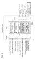
- FIG. 2 is a block diagram for describing functions of an engine ECU.
- the engine ECU 10A includes an engine-signal input part 10A1 to which various sensor signals related to an operational state of the engine are inputted, an engine control part 10A2 for controlling the operational state of the engine, and an engine-signal output part 10A3 for outputting control command values or the like for various devices calculated by the engine control part 10A2.
- FIG. 3 is a block diagram for describing functions of a turbo ECU.
- the turbo ECU 10B includes a turbo signal input part 10b1 to which at least sensor signals related to an operational state of the turbocharger 4 are inputted, from among various signals related to the operational state of the engine, a turbo control part 10B2 which computes a margin or the like described below of the turbocharger 4, and a turbo signal output part 10B3 which outputs the margin or the like computed by the turbo control part 10B2.
- Various sensor signals related to an operational state of the engine are inputted to the engine-signal input part 10A1 of the engine ECU 10A, the sensor signals including: an engine rotation speed detected by a rotation-speed sensor 30; an acceleration signal detected by an accelerator-position sensor (not illustrated); an air-fuel ratio detected by an air-fuel ratio sensor 31; a boost pressure detected by a pressure sensor 32; an intake flow rate detected by an air-flow meter 33; an exhaust temperature detected by an exhaust-temperature sensor 34; a valve-opening degree of the waste-gate valve 12; a turbo rotation speed detected by a turbo rotation speed sensor 35; and a surge-pressure margin, a rotation-speed margin, and an exhaust margin computed by the turbo ECU 10B.
- the engine control part 10A2 of the engine ECU 10A computes control command values for various devices, such as a fuel-injection amount, an ignition timing, and a throttle opening degree, on the basis of various sensor signals inputted into the engine-signal input part 10A1.
- the computed control command values are outputted from the engine-signal output part 10A3 to various devices.
- the engine control part 10A2 computes a W/G valve opening-degree command value (turbo control command value), which is a control command value for the waste-gate valve 12 (boost-pressure control unit), to control a boost pressure of the turbocharger 4.
- the computed W/G valve opening-degree command value is outputted from the engine-signal output part 10A3 to the turbocharger 4 via the turbo ECU 10B.
- an engine rotation speed, an accelerator signal, a boost pressure, an intake flow rate, an exhaust temperature, a valve opening degree of the waste-gate valve 12, and a turbo rotation speed are inputted from the various sensors, at least as sensor signals related to an operational state of the turbocharger 4.
- a W/G valve opening-degree command value outputted from the engine ECU 10A is inputted.
- the turbo control part 10B2 of the turbo ECU 10B computes a surge-pressure margin, a rotation-speed margin, and an exhaust-temperature margin as follows, on the basis of various sensor signals inputted into the turbo signal input part 10B1.
- the computed surge-pressure margin, rotation-speed margin, and exhaust-temperature margin are outputted from the turbo signal output part 10B3 to the engine ECU 10A.
- the above engine ECU 10A, the turbo ECU 10B, the various sensors, and the various devices, are connected to each other to be communicable via CAN.
- FIG. 4 is a control flowchart of a boost-pressure control unit according to the first embodiment.
- the engine ECU 10A reads in the above described various sensor signals (step E1), and then computes control command values for the various devices, such as a fuel-injection amount, an ignition timing, a throttle opening, and a boost pressure (step E2).
- the turbo ECU 10B reads in the above described various sensor signals (step T1), computes a surge pressure (step T2), and computes each of a surge pressure margin, a rotation-speed margin, and an exhaust-temperature margin (step T3).
- the computed surge-pressure margin, rotation-speed margin, and exhaust-temperature margin are each outputted to the engine ECU 10A.
- the engine ECU 10A computes a correction amount on the basis of each margin, and computes control command values on the basis of the correction amount, and output the control command values to the various devices (step E3). From among the control command values, a W/G valve opening-degree command value is outputted to the turbo ECU 10B.
- the turbo ECU 10B performs a feedback control so as to match the valve opening degree of the waste-gate valve 12 to the W/G valve opening-degree command value (step T4).
- FIG. 5 is a diagram for describing computation logics for computing a surge-pressure margin
- FIGs. 6A and 6B are diagrams for describing computation logics for computing a rotation-speed margin
- FIGs. 7A and 7B are diagrams for describing computation logics for computing an exhaust-temperature margin.
- a surge-pressure margin As illustrated in FIG. 5 , to compute a surge-pressure margin, firstly, an intake flow rate and a W/G valve opening degree are inputted to a surge-pressure map M1 to calculate a surge pressure ratio, and the surge pressure ratio is multiplied by an atmospheric pressure to obtain a surge pressure. It should be noted that a turbo rotation speed or another parameter related to a turbo rotation speed may be inputted instead of a W/G valve opening degree.
- the surge pressure refers to a limit pressure at which surging occurs. From the calculated surge pressure and a boost pressure detected by the pressure sensor 32, a surge-pressure margin represented by the following expression (1) is computed.
- Surge ⁇ pressure margin % Surge pressure ⁇ boost pressure / surge pressure ⁇ 100
- a rotation-speed margin is computed as smaller one of a maximum allowable rotation-speed margin or a steady rotation-speed allowable time margin.
- the maximum allowable rotation-speed margin refers to a margin with respect to the maximum allowable rotation speed that the turbocharger 4 can tolerate, as represented by the following expression (2).
- Maximum allowable rotation ⁇ speed margin % Maximum allowable rotation speed ⁇ turbo rotation speed / Maximum allowable rotation speed ⁇ 100
- steady rotation-speed allowable time margin is expressed by the following expression (3).
- Steady rotation ⁇ speed allowable time margin % Maximum allowable duration ⁇ at ⁇ least ⁇ steady ⁇ allowable ⁇ rotation ⁇ speed elapsed time / maximum allowable duration ⁇ 100
- At-least-steady-allowable-rotation-speed elapsed time is an elapsed time shown in FIG. 6A during which the turbo rotation speed of the turbocharger 4 does not exceed the maximum allowable rotation speed but continuously exceeds a steady allowable rotation speed
- the maximum allowable duration is a limit length of time for which continuous excess over the steady allowable rotation speed is permitted.
- an exhaust-temperature margin is computed as the smaller one of a maximum allowable temperature margin and a steady temperature allowable time margin.
- the maximum allowable temperature margin refers to a margin with respect to the maximum allowable temperature that the turbine 4b of the turbocharger 4 can tolerate, as represented by the following expression (4).
- Maximum allowable temperature margin % Maximum allowable temperature ⁇ exhaust temperature ⁇ exhaust temperature / maximum allowable temperature ⁇ 100
- steady temperature allowable time margin is expressed by the following expression (5).
- Steady temperature allowable time margin % Maximum allowable continuance time ⁇ at ⁇ least ⁇ steady ⁇ allowable ⁇ Temperature elapsed time / maximum allowable duration ⁇ 100.
- At-least-steady-allowable-temperature elapsed time is an elapsed time shown in FIG. 7A during which the turbine 4b of the turbocharger 4 does not exceed the maximum allowable temperature but continuously exceeds a steady allowable temperature
- the maximum allowable duration is a limit length of time for which continuous excess over the steady allowable temperature is permitted.
- the accordingly-computed surge-pressure margin, rotation-speed margin, and exhaust-temperature margin are each outputted to the engine ECU 10A as illustrated in FIG. 4 (step T3).
- the engine ECU 10A computes a correction amount on the basis of each margin, computes control command values on the basis of the correction amount, and outputs the control command values to the various devices (step E3).
- margins such as a surge-pressure margin and a rotation-speed margin are used mainly in computation of a W/G valve opening-degree command value.
- An exhaust-temperature margin is used mainly in computation of a control command value of a fuel injection amount.
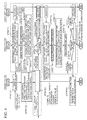
- FIG. 8 is a diagram for describing computation logics for computing a W/G valve opening-degree command value.
- FIG. 9 is a diagram for describing computation logics for computing a control command value related to a fuel injection amount.
- a W/G valve opening-degree command value As illustrated in FIG. 8 , to compute a W/G valve opening-degree command value, an engine rotation speed and an accelerator signal are inputted into a target boost-pressure map M2 to obtain a target boost pressure. Then, a correction amount computed on the basis of a margin or the like by the following method is subtracted from the obtained target boost pressure to calculate a target boost-pressure corrected value. A feedback control for a boost pressure detected by the pressure sensor 32 is performed to compute a W/G valve opening degree for a difference between a target boost-pressure corrected value and a boost pressure.
- a value calculated by inputting an engine rotation speed and an accelerator signal to a W/G valve opening-degree map M3 is added, and thereby a W/G valve opening-degree command value is calculated.
- This computation is performed by a turbo control command value computation part 10A2a of the engine control part 10A2 depicted in FIG. 2 .
- the above logic additionally includes a W/G valve opening-degree map M3 as a feed forward circuit to improve responsiveness, the W/G valve opening-degree map M3 may be removed from the above logic to provide a simpler feedback control circuit.
- an engine rotation speed, an accelerator signal, and the like are inputted into an air-fuel ratio target value map M4, to calculate a target air-fuel ratio.
- a feedback control for an air-fuel ratio detected by the air-fuel ratio sensor 31 is performed to compute a fuel injection amount.
- a correction amount computed on the basis of an exhaust-temperature margin or the like by the following method is subtracted from the calculated fuel injection amount to calculate a control command value for a fuel injection amount. This computation is performed by an engine control part 10A2 depicted in FIG. 2 .
- FIG. 10 is a diagram for describing computation logics for computing a correction amount to be used in computation of a control command value.
- a correction amount is calculated by, if each of a surge-pressure margin, a rotation-speed margin, and an exhaust-temperature margin is below a margin limit, multiplying a difference between the margin limit and each margin by a gain.
- a correction amount changes in accordance with the magnitude of a margin, and is calculated to be greater with a decrease in the margin.
- a margin limit may be set as a constant value in advance
- a margin limit may be calculated by inputting an engine rotation speed and an accelerator signal to a margin limit map M5 as shown in FIG. 10 .
- a suitable margin limit taking account of an operational state of the engine.
- an accumulated operational time may be inputted to the margin limit map M5 so as to calculate a greater margin limit with an increase in the accumulated operational time. In this way, it is possible to further enhance safety against surging for an engine with a longer accumulated operational time.
- a gain may also be set as a constant value in advance
- a gain may be calculated by inputting an engine rotation speed, an accelerator signal, and the like to a gain map M6 as shown in FIG. 10 , which makes it possible to calculate a suitable gain taking account of an operational state of the engine.
- the control device 10 of the supercharging system of the present embodiment has the above configuration, and computes a target boost-pressure corrected value by using a margin (surge margin), which is a numeral index representing a margin with respect to surging, and correcting a target boost pressure in accordance with the magnitude of the margin.
- the waste-gate valve 12 boost-pressure control unit
- the valve opening degree of the waste-gate valve 12 changes in accordance with the magnitude of the margin.
- control device 10 of the supercharging system includes the turbo ECU 10B including a control part and a signal input part provided separately and independently from the engine ECU 10A.
- the turbo ECU 10B is different from the engine ECU 10A in that the turbo ECU10B only performs control of the turbocharger 4.
- the turbo control part 10B2 of the turbo ECU 10B computes a margin, which makes it possible to compute a margin quickly and accurately.
- a surge-pressure margin is used as a margin for computing a correction amount to correct a target boost pressure, which makes it possible to control the waste-gate valve 12 accurately while preventing surging securely.
- a margin may include a rotation-speed margin in addition to a surge-pressure margin.
- the smaller one of a surge-pressure margin or a rotation-speed margin may be used as a margin.
- the rotation-speed margin being defined as the smaller one of the maximum allowable rotation-speed margin or the steady rotation-speed allowable time margin, the turbocharger 4 does not exceed the maximum allowable rotation speed, but is permitted to exceed the steady allowable rotation speed (rated rotation speed of the turbocharger 4) temporarily. In this way, it is possible to perform such a control that maximizes performance of the turbocharger 4.
- a fuel injection amount is corrected by a correction amount computed on the basis of an exhaust-temperature margin.
- correction is performed to reduce a fuel injection amount if an exhaust temperature becomes too high, and thereby an exhaust temperature is reduced.
- it is possible to prevent damage to the turbine 4b of the turbocharger 4 due to an excessive increase in an exhaust temperature.
- the turbo ECU 10B has an autonomous-protection function to re-compute a margin (surge-pressure margin, rotation-speed margin) of the turbocharger 4 on the basis of sensor signals related to an operational state of the turbocharger 4 after the waste-gate valve 12 is controlled on the basis of a W/G valve opening-degree command value (turbo control command value), and to correct the W/G valve opening-degree command value in accordance with the magnitude of the re-computed margin and output the corrected W/G valve opening-degree command value to the waste-gate valve 12 (boost-pressure control unit).
- a margin surge-pressure margin, rotation-speed margin
- step T5 After the waste-gate valve 12 is controlled in step T4 of the control flow shown in FIG. 4 and an operational state of the turbocharger 4 changes, the above described various sensor signals are read in again (step T5), a surge pressure is computed as shown in FIG. 5 (step T6), and a surge-pressure margin, a rotation-speed margin, and an exhaust-temperature margin are each re-computed as shown in FIGs. 5 to 8 (step T7). Then, as illustrated in FIG.
- a margin limit is read in from the margin limit map M5 (step T8), the re-computed margin and the margin limit are compared (step T9), and a W/G valve opening-degree command value is corrected if the re-computed margin is not greater than the margin limit, and the corrected W/G valve opening-degree command corrected value is outputted to the waste-gate valve 12 (step T10).
- the steps T8 to T10 are performed by a turbo control command value correction computation part 10B2a of the turbo control part 10B2.
- the engine ECU 10A computes a W/G valve opening-degree command value corresponding to the above described target boost-pressure corrected value, and the W/G valve opening-degree command value is outputted to the waste-gate valve 12 to control the waste-gate valve 12.
- the engine ECU 10A having complicated control logics and hardware configuration is to control the waste-gate valve 12 as described above, communication delay of the engine ECU 10A may be a problem, as described above.
- turbo ECU 10B having the above autonomous-protection function, it is possible to control the waste-gate valve 12 with the turbo ECU 10B quickly to avoid surging more securely, if the engine ECU 10A cannot control in time or if correction is so insufficient that surging cannot be avoided, for instance.
- the above turbo ECU 10B outputs the corrected W/G valve opening-degree command value (turbo control command value) also to the engine ECU 10A, when outputting the corrected W/G valve opening-degree command value to the waste-gate valve 12.
- the turbo ECU 10B controls the waste-gate valve 12 autonomously by the autonomous-protection function
- the content of the control is transmitted also to the engine ECU 10A.
- the engine ECU 10A can control the waste-gate valve 12 from then on, or control other devices, taking account of the transmitted content of the control.
- the turbo ECU 10B may autonomously store control of the waste-gate valve 12, which makes it possible to utilize the stored data for diagnosis of malfunction during maintenance (step E4).
- FIG. 11 is an overall configuration diagram of an engine system to which a control device of a supercharging system according to the second embodiment of the present invention is to be applied.
- the engine system 1a of the present embodiment is basically similar to the embodiment illustrated in FIG. 1 in terms of configuration, except that the engine system 1a does not include the bypass channel 14 and the waste-gate valve 12. Thus, the same component is associated with the same reference numeral and not described in detail.
- the turbocharger 4 is a variable turbocharger including the turbine 4b driven to rotate by exhaust energy of exhaust gas discharged from the engine 6, the compressor 4a driven coaxially with the turbine 4b, and a variable control mechanism 4d for controlling a flow of exhaust gas that flows into the turbine 4b.
- the variable control mechanism 4d is adjusted to control a flow of exhaust gas flowing into the turbine 4b, and thereby the boost pressure of the turbocharger 4 is controlled.
- variable control mechanism 4d corresponds to a boost-pressure control unit which controls a boost pressure of intake air compressed by the compressor 4a.
- the above turbocharger 4 for instance, includes a variable-displacement type turbocharger equipped with a variable nozzle mechanism 4d including a plurality of nozzle vanes disposed rotatably on the outer periphery of the turbine 4b.
- variable control mechanism 4d which is a boost-pressure control unit, is adjusted to control a flow of exhaust gas flowing into the turbine 4b to control a boost pressure of the turbocharger 4, which makes it possible to prevent surging in advance while suppressing rapid fluctuation of a boost pressure.
- FIG. 12 is an overall configuration diagram of an engine system to which a control system of a supercharging system according to the third embodiment of the present invention is to be applied.
- the engine system 1b of the present embodiment is basically similar to the embodiment illustrated in FIG. 1 in terms of configuration, except for the two-stage turbo-charging system including two turbochargers, a high-pressure stage turbocharger 4A and a low-pressure stage turbocharger 4B.
- the same component is associated with the same reference numeral and not described in detail.
- the supercharger for compressing intake air to be supplied to the engine 6 includes the high-pressure stage turbocharger 4A and the low-pressure stage turbocharger 4B.
- the high-pressure stage turbocharger 4A includes a high-pressure stage turbine 4Ab disposed in the exhaust duct 5 of the engine 6 and driven to rotate by exhaust energy from the engine 6 and a high-pressure stage compressor 4Aa disposed in the intake duct 3 of the engine 6 and driven coaxially with the high-pressure stage turbine 4Ab.
- the low-pressure stage turbocharger 4B includes a low-pressure stage turbine 4Bb disposed in the exhaust duct 5 and on the downstream side of the high-pressure stage turbine 4Ab and a low-pressure stage compressor 4Ba disposed in the intake duct 3 and on the upstream side of the high-pressure stage compressor 4Aa and driven coaxially with the low-pressure stage turbine 4Bb.
- a high-pressure stage bypass channel 14A that bypasses the high-pressure stage turbine 4Ab and a low-pressure stage bypass channel 14B that bypasses the low-pressure stage turbine 4Bb are connected to the exhaust duct 5 of the engine 6.
- a high-pressure stage waste-gate valve 12A is disposed in the high-pressure stage bypass channel 14A, and a low-pressure stage waste-gate valve 12B is disposed in the low-pressure stage bypass channel 14B.
- the above described control device 10 adjusts the valve opening degrees of the high-pressure stage waste-gate valve 12A and the low-pressure stage waste-gate valve 12B individually, thereby controlling the boost pressures of the high-pressure stage turbocharger 4A and the low-pressure stage turbocharger 4B individually. That is, in the present embodiment, each of the high-pressure stage waste-gate valve 12A and the low-pressure stage waste-gate valve 12B corresponds to a boost-pressure control unit of the present invention.
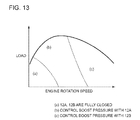
- FIG. 13 is a two-dimensional map related to a control flag, where x-axis is an engine rotation speed and y-axis is a load.
- FIG. 14 is a diagram corresponding to FIG. 13 , for describing operation of two waste-gate valves and a flow of exhaust gas. The arrow in FIG. 14 indicates a flow direction of exhaust gas.
- the two waste-gate valves 12A, 12B are both controlled to be fully closed in a low-speed region (a).
- exhaust gas does not flow through the high-pressure stage bypass channel 14A and the low-pressure stage bypass channel 14B but flows into the high-pressure stage turbine 4Ab and the low-pressure stage turbine 4Bb through the exhaust duct 5, as illustrated in FIG. 14A .
- the high-pressure stage turbine 4Ab and the low-pressure stage turbine 4Bb are driven to rotate, and the high-pressure stage compressor 4Aa and the low-pressure stage compressor 4Ba are driven coaxially in association.
- intake air to be supplied to the engine 6 is supercharged.
- the boost pressure of the high-pressure stage compressor 4A becomes particularly high, which raises a risk of surging.
- the valve opening degree of the high-pressure stage waste-gate valve 12A is adjusted to reduce a flow rate of exhaust gas flowing through the high-pressure stage turbine 4Ab, and the boost pressure of the high-pressure stage compressor 4Aa is controlled.
- the boost pressure of the low-pressure stage compressor 4Ba is lower than the boost pressure of the high-pressure stage compressor 4A and surging may not occur.
- the low-pressure stage waste-gate valve 12B is controlled to be kept in a fully-closed state.
- the high-pressure stage waste-gate valve 12A is controlled to be fully open, so that exhaust gas does not flow into the high-pressure stage turbine 4Ab. Further, in the high-speed region, the boost pressure of the low-pressure stage compressor 4B also increases, which raises a risk of surging. Thus, in the high-speed region (c), the valve opening degree of the low-pressure stage waste-gate valve 12B is adjusted to reduce a flow rate of exhaust gas flowing through the low-pressure stage turbine 4Bb, and the boost pressure of the low-pressure stage compressor 4Ba is controlled.
- FIG. 15 is a diagram for describing computation logics for computing two W/G valve opening-degree command values, corresponding to FIG. 8 of the first embodiment.
- an engine rotation speed and an accelerator signal are inputted into the target boost-pressure map M2 to calculate a target boost pressure.
- a correction amount computed on the basis of a margin or the like by the above-described method is subtracted from the calculated target boost pressure to calculate a target boost-pressure corrected value.
- a feedback control for a boost pressure detected by the pressure sensor 32 is performed to compute a W/G valve opening degree for a difference between a target boost-pressure corrected value and a boost pressure for each of the high-pressure stage waste-gate valve 12A and the low-pressure stage waste-gate valve 12B.
- an engine rotation speed and an accelerator signal are inputted into a control flag map M5 shown in FIG. 13 to determine which of the above operational regions (a), (b), and (c) corresponds to an operational state of the engine 6, and a result is outputted as a control flag.
- a W/G valve opening degree is computed in accordance with this control flag, so as to correspond to the content of a boost-pressure control in an operational state shown in FIG. 14 .
- the W/G valve opening degrees of the high-pressure stage waste-gate valve 12A and the low-pressure stage waste-gate valve 12B are computed to be fully closed.
- a control flag (b) is outputted, the W/G valve opening degree of the low-pressure stage waste-gate valve 12B is computed to be fully closed, and the W/G valve opening degree of the high-pressure stage waste-gate valve 12A is computed so that the boost pressure of the high-pressure stage turbocharger 4A reaches the target boost pressure.
- the W/G valve opening degree of the high-pressure stage waste-gate valve 12A is computed to be fully open, and the W/G valve opening degree of the low-pressure stage waste-gate valve 12B is computed so that the boost pressure of the high-pressure stage turbocharger 4A reaches the target boost pressure.
- values calculated by inputting an engine rotation speed and an accelerator signal to W/G valve opening-degree maps M3A, M3B are added, and thereby a W/G valve opening-degree command value is calculated for each of the high-pressure stage waste-gate valve 12A and the low-pressure stage waste-gate valve 12B.
- the valve opening degree of the high-pressure stage waste-gate valve 12A being the boost-pressure control unit for the high-pressure stage turbocharger 4A and the valve opening degree of the low-pressure stage waste-gate valve 12B being the boost-pressure control unit for the low-pressure stage turbocharger 4B are adjusted, and thereby the boost pressures of the high-pressure stage turbocharger 4A and the low-pressure stage turbocharger 4B are controlled, which makes it possible to prevent occurrence of surging in advance while suppressing rapid fluctuation of the boost pressures.
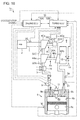
- FIG. 16 is an overall configuration diagram of an engine system to which a control device of a supercharging system according to the fourth embodiment of the present invention is to be applied.
- the engine system 1c of the present embodiment is basically similar to the embodiment illustrated in FIG. 1 in terms of configuration, except for the two-stage turbo-charging system including two turbochargers, the turbocharger 4A and an electric turbocharger 4C.
- the same component is associated with the same reference numeral and not described in detail.
- a turbocharger for compressing intake air to be supplied to the engine 6 includes the turbocharger 4A and the electric turbocharger 4C.
- the turbocharger 4A includes the turbine 4Ab disposed in the exhaust duct 5 of the engine 6 and driven to rotate by exhaust energy from the engine 6, and the compressor 4Aa disposed in the intake duct 3 of the engine 6 and driven coaxially with the turbine 4Ab.
- the electric turbocharger 4C includes an electric compressor 4Ca disposed upstream of the compressor 4Aa of the turbocharger 4A, a motor 4Cd for driving the electric compressor 4Ca to rotate, and an inverter 4Ce (rotation-speed control unit) which controls a rotation speed of the motor 4Cd.
- the bypass channel 14 bypassing the turbine 4Ab is connected to the exhaust duct 5 of the engine 6, and the waste-gate valve 12 is disposed in the bypass channel 14.
- the boost pressure of the turbocharger 4A is controlled by adjusting the valve opening degree of the waste-gate valve 12. Further, the rotation speed of the motor 4Cd is controlled by the inverter 4Ce to control the boost pressure of the electric turbocharger 4C. That is, in the present embodiment, each of the waste-gate valve 12 and the inverter 4Ce corresponds to a boost-pressure control unit of the present invention.
- FIG. 17 is a control flowchart of a boost-pressure control unit according to the fourth embodiment, corresponding to FIG. 4 of the first embodiment.
- the same component also shown in FIG. 4 is associated with the same reference numeral and not described in detail.
- a motor rotation-speed command value which is a control command value for the inverter 4Ce, is computed in addition to a W/G valve opening-degree command value (turbo control command value) for the waste-gate valve 12.
- the computed motor rotation-speed command value is outputted to the turbo ECU 10B, and the turbo ECU 10B controls the output of the inverter 4Ce (step T4'), which differentiates the present embodiment from the above described first embodiment.
- step T9 the margin re-computed in step T9 is compared with a margin limit, and if the recomputed margin is not greater than a margin limit, not only the W/G valve opening-degree command value but also the motor rotation-speed command value is corrected, and the corrected motor rotation-speed command corrected value is outputted to the inverter 4Ce (step T10'), which differentiates the present embodiment from the above described first embodiment.
- the valve opening degree of the waste-gate valve 12 being the boost-pressure control unit for the turbocharger 4A is adjusted, and the rotation speed of the motor 4Cd is controlled with the inverter 4Ce being the boost-pressure control unit for the electric turbocharger 4C, and thereby the boost pressure of each of the turbocharger 4A and the electric turbocharger 4C is controlled, which makes it possible to prevent occurrence of surging in advance while suppressing rapid fluctuation of the boost pressure.
- the electric turbocharger 4C is disposed on a low-pressure stage side.
- the positions of the turbocharger 4A and the electric turbocharger 4C may be switched so that the electric turbocharger 4C is disposed on a high-pressure stage side.
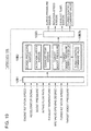
- FIG. 18 is a block diagram for describing functions of an engine ECU according to the fifth embodiment.
- FIG. 19 is a block diagram for describing functions of a turbo ECU according to the fifth embodiment.
- the overall configuration of an engine system according to the present embodiment is the same as that in the first embodiment depicted in FIG. 1 , and thus not described again in detail.
- the engine ECU 10A of the present embodiment is different from the first embodiment in that, as illustrated in FIG. 18 , the engine control part 10A2 does not compute a W/G valve opening-degree command value (turbo control command value).
- the engine ECU 10A computes a target boost pressure, and the computed target boost pressure is outputted to the turbo ECU 10B.
- the turbo ECU 10B corrects the target boost pressure on the basis of a margin computed by the turbo control part 10B2 to compute a target boost-pressure corrected value, and also computes a W/G valve opening-degree command value corresponding to the target boost-pressure corrected value.
- the computed W/G valve opening-degree command value (turbo control command value) is outputted to the waste-gate valve 12.
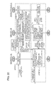
- FIG. 20 is a control flowchart of a boost-pressure control unit according to the fifth embodiment.
- the engine ECU 10A reads in the above described various sensor signals (step E1), and then computes control command values for the various devices, such as a fuel-injection amount, an ignition timing, a throttle opening, and a boost pressure, and also computes a target boost pressure (step E2).
- the turbo ECU 10B reads in the above described various sensor signals (step T1), computes a surge pressure (step T2), and computes a margin such as a surge pressure margin, a rotation-speed margin, and an exhaust-temperature margin (step T3).
- the turbo ECU 10B corrects the target boost pressure on the basis of a margin to compute a target boost-pressure corrected value, and also computes a W/G valve opening-degree command value corresponding to the target boost-pressure corrected value.
- the computed target boost-pressure corrected value is also outputted to the engine ECU 10A.
- the turbo ECU 10B performs a feedback control so as to match the valve opening degree of the waste-gate valve 12 to the W/G valve opening-degree command value (step T4).
- FIG. 21 is a diagram for describing computation logics for computing a W/G valve opening-degree command value.
- a correction amount computed on the basis of a margin or the like by the above-described method is subtracted from the target boost pressure computed by the engine ECU 10A to calculate a target boost-pressure corrected value.
- a feedback control for a boost pressure detected by the pressure sensor 32 is performed to compute a W/G valve opening degree for a difference between a target boost-pressure corrected value and a boost pressure.
- a value calculated by inputting an engine rotation speed and an accelerator signal to a W/G valve opening-degree map M3 is added, and thereby a W/G valve opening-degree command value is calculated. This computation is performed by a turbo control command value computation part 10B2b of the turbo control part 10B2 illustrated in FIG. 19 .
- a target boost-pressure corrected value is computed by the turbo ECU 10B, and a W/G valve opening-degree command value (turbo control command value) corresponding to the target boost-pressure corrected value is computed, and the W/G valve opening-degree command value is outputted to the waste-gate valve 12.
- the turbo ECU 10B itself performs the entire control of the boost-pressure control unit, and does not need to communicate with the engine ECU 10A, which makes it possible to control the boost-pressure control unit quickly while avoiding an influence from communication delay of the engine ECU 10A.
- the turbo ECU 10B outputs the computed target boost-pressure corrected value also to the engine ECU 10A.
- the engine ECU 10A can reflect the target boost-pressure corrected value computed by the turbo ECU 10B to control the boost-pressure control unit from then on, or to control other devices.
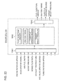
- FIG. 22 is a block diagram for describing functions of an engine ECU according to the sixth embodiment.
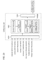
- FIG. 23 is a block diagram for describing functions of a turbo ECU according to the sixth embodiment.
- the overall configuration of an engine system according to the present embodiment is the same as that in the first embodiment depicted in FIG. 1 , and thus not described again in detail.
- the engine ECU 10A of the present embodiment is different from the first embodiment in that, as illustrated in FIG. 22 , the engine control part 10A2 does not compute a W/G valve opening-degree command value (turbo control command value).
- the engine ECU 10A computes a target boost pressure, and the computed target boost pressure is outputted to the turbo ECU 10B. This is similar to the above described fifth embodiment.
- the turbo control part 10B2 does not compute a margin as described above. Instead, the turbo control part 10B2 computes a surge pressure which is a limit pressure at which surging occurs, on the basis of sensor signals such as a boost pressure and an intake flow rate inputted into the turbo signal input part 10b1. A pressure value corresponding to a predetermined margin limit is subtracted from the computed surge pressure to calculate an upper limit pressure. The upper limit pressure and the target boost pressure are compared, and if the target boost pressure is larger than the upper limit pressure, the target boost pressure is corrected so as to obtain a target boost pressure corrected value equal to the upper limit pressure.
- the margin limit is set as a constant value that does not change with time in accordance with a change in an operational state (engine rotation speed or accelerator signal) of the engine, such as 5%, 10%, and 15%. Thus, it is no longer necessary to compute a margin limit repetitively with time in accordance with a change in an operational state of the engine, unlike the above described embodiments. Thus, it is possible to simplify computation logics of the turbo controller 10B.
- FIG. 24 is a control flowchart of a boost-pressure control unit according to the sixth embodiment.
- the engine ECU 10A reads in the above described various sensor signals (step E1), and then computes control command values for the various devices, such as a fuel-injection amount, an ignition timing, a throttle opening, and a boost pressure, and also computes a target boost pressure (step E2).
- the turbo ECU 10B reads in the above described various sensor signals (step T1), computes a surge pressure (step T2), and computes an upper limit pressure from the surge pressure and a predetermined margin limit (step T3).
- the upper limit pressure and the target boost pressure are compared (step T4), and if the upper limit pressure is greater than the target boost pressure (YES in step T4), the target boost pressure is not corrected (i.e., "target boost pressure” is set to be equal to “target boost pressure corrected value”), and a W/G valve opening-degree command value corresponding to the target boost pressure corrected value (target boost pressure) is computed (step T6). If the upper limit pressure is not greater than the target boost pressure (NO in step T4), a target boost-pressure corrected value is computed so that the target boost-pressure corrected value equals to the upper limit pressure (step T5), and a W/G valve opening-degree command value corresponding to the target boost-pressure corrected value (upper limit pressure) is computed (step T6). Further, an indication (correction flag) of having corrected the target boost pressure for matching the target boost-pressure corrected value to the upper limit pressure and the target boost-pressure corrected value are transmitted to the engine ECU 10A.
- FIG. 25 is a diagram for describing computation logics for computing a W/G valve opening-degree command value.
- a W/G valve opening-degree command value firstly, an intake flow rate and a W/G valve opening degree are inputted to a surge-pressure map M1 to calculate a surge pressure ratio, and the surge pressure ratio is multiplied by an atmospheric pressure to calculate a surge pressure.
- a pressure value corresponding to a predetermined margin limit is subtracted from the surge pressure to compute an upper limit pressure.
- a pressure value corresponding to a margin limit is calculated by multiplying the computed surge pressure by a margin limit.
- the accordingly calculated upper limit pressure and the target boost pressure computed by the engine ECU 10A are compared, and the smaller one is outputted as a target boost-pressure corrected value.
- a feedback control for a boost pressure detected by the pressure sensor 32 is performed to compute a W/G valve opening degree for a difference between a target boost-pressure corrected value and a boost pressure.
- a target boost-pressure corrected value is computed by the turbo ECU 10B, and a W/G valve opening-degree command value (turbo control command value) corresponding to the target boost-pressure corrected value is computed, and the W/G valve opening-degree command value is outputted to the waste-gate valve 12.
- the turbo ECU 10B itself performs the entire control of the boost-pressure control unit, and does not need to communicate with the engine ECU 10A, which makes it possible to control the boost-pressure control unit quickly while avoiding an influence from communication delay of the engine ECU 10A.
- the upper limit pressure and the target boost pressure are compared, and if the target boost pressure is larger than the upper limit pressure, the target boost pressure is corrected so as to match the target boost pressure corrected value with the upper limit pressure, and thus the computation logics for correcting a target boost pressure are simple. Accordingly, it is possible to simplify the computation logics of the turbo controller 10B even compared to those in the fifth embodiment, and to compute a turbo control command value in an instant, which makes it possible to improve control responsiveness of a boost-pressure control unit such as the W/G valve and the VG actuator.
- the turbo controller 10B stores a plurality of margin limit values defined as constant values in advance.
- the plurality of margin limit values are each associated with corresponding one of a plurality of preset operation modes, and a margin limit corresponding to a selected operation mode is selected.
- three margin limits are set in advance, including: the first margin limit (e.g. 10%) corresponding to a normal mode; the second margin limit (e.g. 5%) corresponding to a high-response mode and smaller than the first margin limit; and the third margin limit (e.g. 15%) corresponding to a safety mode and larger than the first margin limit.
- a margin limit corresponding to a selected operation mode may be selected in response to switching of the operation modes by a driver or the like.
- At least one embodiment of the present invention can be suitably used as a control device for a supercharging system for supplying compressed intake air to an engine for an automobile, a ship, or an industrial use.
Landscapes
- Engineering & Computer Science (AREA)
- Chemical & Material Sciences (AREA)
- Combustion & Propulsion (AREA)
- Mechanical Engineering (AREA)
- General Engineering & Computer Science (AREA)
- Supercharger (AREA)
Abstract
Description
- The present disclosure relates to a control device for a supercharging system for supplying compressed intake air to an engine.
- As a technique to improve an output of an engine, a method (supercharging) of compressing intake air with a supercharger and supplying an engine with the compressed intake air is known, and widely used in an engine for an automobile and the like. A supercharger may transitionally enter an abnormal operational state with surging, over-speed, or the like, depending on the operational state of the supercharger. Such abnormal operation may lead to breakage of various devices, and thus needs to be prevented as much as possible.
-
Patent Document 1 discloses an invention, as a control device for a turbocharger, for suppressing surging by predicting occurrence of surging from an operational state of the turbocharger and opening a waste-gate valve immediately before occurrence of surging to reduce a flow rate of exhaust gas flowing to a turbine. -
Patent Document 2 discloses an invention, as a supercharging control device, for suppressing surging by providing a compressor-bypass valve for returning intake air from a downstream side toward an upstream side of a compressor and opening the bypass valve to return intake air if occurrence of surging is predicted. -
Patent Document 3 discloses an invention, as a control device for a variable geometry turbocharger, for suppressing over-speed by changing a vane angle of nozzle vanes to achieve the maximum nozzle area during over-speed of a turbocharger. -
- Patent Document 1:
JP2004-27897A - Patent Document 2:
JP2006-207506A - Patent Document 3:
JPH5-280365A - The inventions disclosed in
Patent Documents 1 to 3 described above are basically intended to determine whether an operational point is within a surge region in which surging may occur, and to control various devices for controlling a boost pressure to reduce the boost pressure if the operational point is within the surge region. Such conventional techniques control various devices to be switched alternatively on the basis of whether an operational point is within the surge region, and thus a boost pressure may rapidly change. Further, the invention disclosed inPatent Document 2 requires additional provision of a compressor-bypass valve, which makes a supercharger larger in size and more complicated. - Further, in accordance with the improvement of the engines in recent years, the control logic and hardware configuration of an engine controller is becoming increasingly complicated. In this context, the techniques disclosed in the
above Patent Documents 1 to 3 have a problem of increasingly complicated control logic and hardware of an engine controller, because functions for preventing surging are installed on the engine controller. Further, if a quickly-changing transitional phenomenon like surging is to be controlled by an engine controller with complicated control logic and hardware configuration, communication delay of the engine controller may be a problem. - At least one embodiment of the present invention was made in view of the above conventional problem, and an object of at least one embodiment is to provide a control device for a supercharging system capable of preventing occurrence of surging in advance while suppressing rapid fluctuation of a boost pressure, and of controlling the boost pressure quickly while avoiding an influence from communication delay.
- In an embodiment of the present invention, a control device for a supercharging system for supplying compressed intake air to an engine, the supercharging system comprising a supercharger configured to compress intake air to be supplied to the engine, a boost-pressure control unit configured to control a boost pressure of the supercharger, and a control device configured to control the boost-pressure control unit, comprises: an engine controller comprising an engine signal input part to which various sensor signals related to an operational state of the engine are to be inputted, and an engine control part configured to control an operational state of the engine and to compute a target boost pressure of the supercharger on the basis of the sensor signals inputted into the engine signal input part; and a turbo controller comprising a turbo signal input part to which at least sensor signals related to an operational state of the supercharger are to be inputted from among the various sensor signals related to an operational state of the engine, and a turbo control part configured to compute a margin of the supercharger on the basis of the sensor signals inputted to the turbo signal input part, the turbo controller comprising a control part and a signal input part provided separately and independently from the engine controller. The control device is configured to compute a target boost-pressure corrected value by correcting the target boost pressure in accordance with a magnitude of the margin computed by the turbo control part, and to control the boost-pressure control unit so that the boost pressure of the supercharger reaches the target boost-pressure corrected value.
- The above control device of the supercharging system computes a target boost-pressure corrected value by using a margin (surge margin), which is a numeral index representing a margin with respect to surging, and correcting a target boost pressure in accordance with the magnitude of the margin. The boost-pressure control unit is controlled so that the boost pressure of the supercharger reaches a target boost-pressure corrected value. With the above control device of the supercharging system, the control amount of the boost-pressure control unit changes in accordance with the magnitude of the margin. Thus, it is possible to prevent surging in advance while reducing rapid fluctuation of a boost pressure, as compared to a typical case in which the boost-pressure control unit is switched alternatively on the basis of whether an operational point is in the surge region.
- Further, the control device of the supercharging system includes the turbo controller including a control part and a signal input part provided separately and independently from the engine controller. The turbo controller is a controller which basically controls only the supercharger, unlike the engine controller, which simultaneously controls a plurality of devices. Thus, with the turbo control part of the turbo controller computing a margin, it is possible to compute a margin quickly and accurately. Accordingly, it is possible to control a boost pressure quickly while avoiding an influence from communication delay which may take place if a margin is computed by the engine controller.
- In some embodiments, the engine controller is configured to compute the target boost-pressure corrected value by correcting the target boost pressure in accordance with the magnitude of the margin, compute a turbo control command value corresponding to the target boost-pressure corrected value, and output the computed turbo control command value to the boost-pressure control unit via the turbo controller. Further, the turbo controller has an autonomous protection function to re-compute a margin of the supercharger on the basis of sensor signals related to an operational state of the supercharger after the boost-pressure control unit is controlled on the basis of the turbo control command value, correct the turbo control command value in accordance with a magnitude of the re-computed margin, and output the corrected turbo control command value to the boost-pressure control unit.
- In the present embodiment, basically, the engine controller computes a turbo control command value corresponding to the above described target boost-pressure corrected value, and the turbo control command value is outputted to the boost-pressure control unit to control the boost-pressure control unit. However, if the engine controller having complicated control logics and hardware configuration is to control the boost-pressure control unit, communication delay of the engine controller may be a problem, as described above. Thus, with the turbo controller having the above autonomous-protection function, it is possible to control the boost-pressure control unit with the turbo controller quickly to avoid surging more securely, if the engine controller cannot control in time or if a case where correction is so insufficient that surging cannot be avoided, for instance.
- In the above embodiment, the turbo controller is configured to output the corrected turbo control command value also to the engine controller when outputting the corrected turbo control command value to the boost-pressure control unit.
- According to this embodiment, if the turbo controller controls the boost-pressure control unit autonomously by the autonomous-protection function, the content of the control is transmitted also to the engine controller. Thus, the engine controller can control the boost-pressure control unit from then on, or control other devices, taking account of the transmitted content of the control. Further, the turbo controller may autonomously store execution of control of the boost-pressure control unit, which makes it possible to utilize the stored data for diagnosis of malfunction during maintenance.
- In some embodiments, the engine controller is configured to output the target boost pressure computed by the engine control part to the turbo controller, and the turbo controller is configured to compute a target boost-pressure corrected value by correcting the target boost pressure on the basis of the margin computed by the turbo control part, compute a turbo control command value corresponding to the target boost-pressure corrected value, and output the computed turbo control command value to the boost-pressure control unit.
- According to this embodiment, basically, a target boost-pressure corrected value is computed by the turbo controller, and a turbo control command value corresponding to the target boost-pressure corrected value is computed, and the turbo control command value is outputted to the boost-pressure control unit. Specifically, the turbo controller itself performs the entire control of the boost-pressure control unit, and does not need to communicate with the engine controller, which makes it possible to control the boost-pressure control unit quickly while avoiding an influence from communication delay of the engine controller.
- In the above embodiment, the turbo controller is configured to output the computed target boost-pressure corrected value also to the engine controller.
- According to this embodiment, the engine controller can reflect the target boost-pressure corrected value computed by the turbo controller to control the boost-pressure control unit from then, on or to control other devices.
- In some embodiments, the margin includes a surge-pressure margin which is a ratio of a difference between a surge pressure and a boost pressure to the surge pressure, where the surge pressure is a limit pressure at which surging occurs.
- was described above, a surge-pressure margin is defined as a ratio of a difference between a surge pressure and a boost pressure to the surge pressure, and thereby it is possible to prevent occurrence of surging securely and to control the boost-pressure control unit accurately.
- In the above embodiment, the margin may include a rotation-speed margin in addition to the surge-pressure margin, the rotation-speed margin being defined as the smaller one of: a maximum allowable rotation-speed margin which is a ratio of a difference between a maximum allowable rotation speed of the supercharger and a rotation speed of the supercharger to the maximum allowable rotation speed; or a steady rotation-speed allowable time margin which is a ratio of a difference between a maximum allowable duration and an elapsed time of continuous excess over a steady allowable rotation speed to the maximum allowable duration, where the steady allowable rotation speed is a rotation speed of the supercharger set to be lower than the maximum allowable rotation speed, and the maximum allowable duration is a limit length of time for which the rotation speed of the supercharger is allowed to exceed the steady allowable rotation speed continuously.
- According to this embodiment, the margin includes the rotation margin defined as described above in addition to the surge-pressure margin, and thereby it is possible to prevent over-speed of the supercharger along with surging. Further, with the rotation-speed margin being defined as the smaller one of the maximum allowable rotation-speed margin or the steady rotation-speed allowable time margin, the supercharger does not exceed the maximum allowable rotation speed, but is permitted to exceed the steady allowable rotation speed (rated rotation speed of the supercharger) temporarily. In this way, it is possible to perform a control such that the performance of supercharger is maximized.
- In some embodiments, the engine controller is configured to correct a fuel injection amount computed on the basis of the sensor signals inputted to the engine signal input part in accordance with a magnitude of an exhaust-temperature margin defined as the smaller one of: a maximum allowable temperature margin which is a ratio of a difference between a maximum allowable temperature of the supercharger and a temperature of exhaust gas flowing through an exhaust duct of the engine to the maximum allowable temperature; or a steady temperature allowable time margin which is a ratio of a difference between a maximum allowable duration and an elapsed time of continuous excess over a steady allowable temperature to the maximum allowable duration, where the steady allowable temperature is a temperature of the supercharger set to be lower than the maximum allowable temperature, and the maximum allowable duration is a limit length of time for which the temperature of the exhaust gas is allowed to exceed the steady allowable temperature continuously.
- According to this embodiment, a fuel injection amount is corrected to decrease if an exhaust temperature becomes too high, and thereby an exhaust temperature is reduced. Thus, it is possible to prevent damage to the turbine of the supercharger due to an excessive increase in the exhaust temperature.
- In some embodiments, the supercharger comprises a turbocharger comprising a turbine disposed in an exhaust duct of the engine and driven to rotate by exhaust energy of exhaust gas discharged from the engine, and a compressor disposed in an intake duct of the engine and driven to rotate coaxially with the turbine. A bypass channel bypassing the turbine is connected to the exhaust duct of the engine, a waste-gate valve is disposed in the bypass channel, and the boost pressure of the supercharger is controlled by adjusting a valve opening degree of the waste-gate valve.
- According to the above embodiment, the boost pressure of the supercharger is controlled by adjusting the valve opening degree of the waste-gate valve, which is a boost-pressure control unit, and thereby it is possible to prevent occurrence of surging in advance while suppressing rapid fluctuation of a boost pressure.
- In some embodiments, the supercharger comprises a variable turbocharger comprising a turbine driven to rotate by exhaust energy of exhaust gas discharged from the engine, a compressor driven to rotate coaxially with the turbine, and a variable control mechanism configured to control a flow of the exhaust gas flowing into the turbine. Further, the boost pressure of the supercharger is controlled by controlling the flow of the exhaust gas flowing into the turbine by adjusting the variable control mechanism.
- According to the above embodiment, the variable control mechanism, which is a boost-pressure control unit, is adjusted to control a flow of exhaust gas flowing into the turbine to control a boost pressure of the supercharger, which makes it possible to prevent surging in advance while suppressing rapid fluctuation of the boost pressure.
- In some embodiments, the supercharger comprises: a high-pressure stage turbocharger comprising a high-pressure stage turbine disposed in an exhaust duct of the engine and driven to rotate by exhaust energy of exhaust gas discharged from the engine, and a high-pressure stage compressor disposed in an intake duct of the engine and driven to rotate coaxially with the high-pressure stage turbine; and a low-pressure stage turbocharger comprising a low-pressure stage turbine disposed in the exhaust duct at a downstream side of the high-pressure stage turbine, and a low-pressure stage compressor disposed in the intake duct at an upstream side of the high-pressure stage compressor and driven to rotate coaxially with the low-pressure stage turbine. A high-pressure stage bypass channel bypassing the high-pressure stage turbine and a low-pressure stage bypass channel bypassing the low-pressure stage turbine are connected to the exhaust duct of the engine, a high-pressure stage waste-gate valve is disposed in the high-pressure stage bypass channel, and a low-pressure stage waste-gate valve is disposed in the low-pressure stage bypass channel. Further, boost pressures of the high-pressure stage turbocharger and the low-pressure stage turbocharger are controlled individually by adjusting respective valve opening degrees of the high-pressure stage waste-gate valve and the low-pressure stage waste-gate valve.
- According to the present embodiment, in a two-stage supercharging system including the high-pressure stage turbocharger and the low-pressure stage turbocharger, the valve opening degree of the high-pressure stage waste-gate valve being the boost-pressure control unit for the high-pressure stage turbocharger and the valve opening degree of the low-pressure stage waste-gate valve being the boost-pressure control unit for the low-pressure stage turbocharger are adjusted, and thereby the boost pressures of the high-pressure stage turbocharger and the low-pressure stage turbocharger are controlled, which makes it possible to prevent occurrence of surging in advance while suppressing rapid fluctuation of the boost pressure.
- In some embodiments, the supercharger comprises: a turbocharger comprising a turbine disposed in an exhaust duct of the engine and driven to rotate by exhaust energy of exhaust gas discharged from the engine, and a compressor disposed in an intake duct of the engine and driven to rotate coaxially with the turbine; and an electric turbocharger comprising an electric compressor disposed upstream or downstream of the compressor of the turbocharger, a motor configured to drive the electric compressor to rotate, and a rotation-speed control unit configured to control a rotation speed of the motor. A bypass channel bypassing the turbine is connected to the exhaust duct of the engine, and a waste-gate valve is disposed in the bypass channel. The boost pressure of the turbocharger is controlled by adjusting a valve opening degree of the waste-gate valve, and a boost pressure of the electric turbocharger is controlled by controlling the rotation speed of the motor with the rotation-speed control unit.
- According to the present embodiment, in a two-stage supercharging system including the turbocharger and the electric turbocharger, the valve opening degree of the waste-gate valve being the boost-pressure control unit for the turbocharger is adjusted, and the rotation speed of the motor is controlled by the rotation-speed control unit being the boost-pressure control unit for the electric turbocharger, and thereby the boost pressure of each of the turbocharger and the electric turbocharger is controlled, which makes it possible to prevent occurrence of surging in advance while suppressing rapid fluctuation of the boost pressure.
- In at least one embodiment of the present invention, a control device for a supercharging system for supplying compressed intake air to an engine, the supercharging system comprising a supercharger configured to compress intake air to be supplied to the engine, a boost-pressure control unit configured to control a boost pressure of the supercharger, and a control device configured to control the boost-pressure control unit, comprises: an engine controller comprising an engine signal input part to which various sensor signals related to an operational state of the engine are to be inputted, an engine control part configured to control an operational state of the engine and to compute a target boost pressure of the supercharger on the basis of the sensor signals inputted into the engine signal input part, and an engine signal output part configured to output the target boost pressure computed by the engine control part; and a turbo controller comprising a turbo signal input part to which at least sensor signals related to an operational state of the supercharger from among the various sensor signals related to an operational state of the engine and the target boost pressure are to be inputted, and a turbo-control part configured to compute a target boost-pressure corrected value by correcting the target boost pressure inputted to the turbo signal input part and compute a turbo control command value corresponding to the target boost-pressure corrected value, and a turbo signal output part configured to output the turbo control command value computed by the turbo control part to the boost-pressure control unit, the turbo controller comprising a control part and a signal input-output part provided separately and independently from the engine controller. The turbo control part is configured to compute a surge pressure which is a limit pressure at which surging occurs, on the basis of the sensor signals inputted to the turbo signal input part, compute an upper-limit pressure by subtracting a pressure value corresponding to a margin limit value defined in advance as a constant value from the computed surge pressure, and compare the upper-limit pressure with the target boost pressure and correct the target boost pressure so that the target boost-pressure corrected value coincides with the upper-limit pressure if the target boost pressure is larger than the upper-limit pressure.
- According to this embodiment, a target boost-pressure corrected value is computed by the turbo controller, and a turbo control command value corresponding to the target boost-pressure corrected value is computed, and the turbo control command value is outputted to the boost-pressure control unit. Specifically, the turbo controller itself performs the entire control of the boost-pressure control unit, and does not need to communicate with the engine controller, which makes it possible to control the boost-pressure control unit quickly while avoiding an influence from communication delay of the engine controller.
- Further, in the present embodiment, the upper limit pressure and the target boost pressure are compared, and if the target boost pressure is larger than the upper limit pressure, the target boost pressure is corrected so as to match the target boost pressure corrected value with the upper limit pressure, and thus the computation logics for correcting a target boost pressure are simple. Accordingly, it is possible to simplify the computation logics of the turbo controller, and to compute a turbo control command value in an instant, which makes it possible to improve control responsiveness of a boost-pressure control unit such as the W/G valve and the VG actuator.
- According to at least one embodiment of the present invention, it is possible to provide a control device for a supercharging system capable of preventing occurrence of surging in advance while suppressing rapid fluctuation of a boost pressure, and of controlling the boost pressure quickly while avoiding an influence from communication delay.
-
-
FIG. 1 is an overall configuration diagram of an engine system to which a control device of a supercharging system according to the first embodiment of the present invention is to be applied. -
FIG. 2 is a block diagram for describing functions of an engine ECU. -
FIG. 3 is a block diagram for describing functions of a turbo ECU. -
FIG. 4 is a control flowchart of a boost-pressure control unit according to the first embodiment. -
FIG. 5 is a diagram for describing computation logics for computing a surge-pressure margin. -
FIG. 6 is a diagram for describing computation logics for computing a rotation-speed margin. -
FIG. 7 is a diagram for describing computation logics for computing an exhaust-temperature margin. -
FIG. 8 is a diagram for describing computation logics for computing a W/G valve opening-degree command value. -
FIG. 9 is a diagram for describing computation logics for computing a control command value related to a fuel injection amount. -
FIG. 10 is a diagram for describing computation logics for computing a correction amount to be used in computation of a control command value. -
FIG. 11 is an overall configuration diagram of an engine system to which a control device of a supercharging system according to the second embodiment of the present invention is to be applied. -
FIG. 12 is an overall configuration diagram of an engine system to which a control device of a supercharging system according to the third embodiment of the present invention is to be applied. -
FIG. 13 is a two-dimensional map related to a control flag, where x-axis is an engine rotation speed and y-axis is a load. -
FIG. 14 is a diagram corresponding toFIG. 13 , for describing operation of two waste-gate valves and a flow of exhaust gas. -
FIG. 15 is a diagram for describing computation logics for computing two W/G valve opening-degree command values. -
FIG. 16 is an overall configuration diagram of an engine system to which a control device of a supercharging system according to the fourth embodiment of the present invention is to be applied. -
FIG. 17 is a control flowchart of a boost-pressure control unit according to the fourth embodiment. -
FIG. 18 is a block diagram for describing functions of an engine ECU according to the fifth embodiment. -
FIG. 19 is a block diagram for describing functions of a turbo ECU according to the fifth embodiment. -
FIG. 20 is a control flowchart of a boost-pressure control unit according to the fifth embodiment. -
FIG. 21 is a diagram for describing computation logics for computing a W/G valve opening-degree command value. -
FIG. 22 is a block diagram for describing functions of an engine ECU according to the sixth embodiment. -
FIG. 23 is a block diagram for describing functions of a turbo ECU according to the sixth embodiment. -
FIG. 24 is a control flowchart of a boost-pressure control unit according to the sixth embodiment. -
FIG. 25 is a diagram for describing computation logics for computing a W/G valve opening-degree command value. - Embodiments of the present invention will now be described in more detail with reference to the accompanying drawings.
- However, the scope of the present invention is not limited to the following embodiments. It is intended that dimensions, materials, shapes, relative positions and the like of components described in the embodiments shall be interpreted as illustrative only and not limitative of the scope of the present invention.
-
FIG. 1 is an overall configuration diagram of an engine system to which a control device of a supercharging system according to the first embodiment of the present invention is to be applied. - In the
engine system 1 according to the present embodiment illustrated inFIG. 1 , air (intake air) introduced into anintake duct 3 via anair cleaner 2 flows into acompressor 4a of a turbocharger 4 (supercharger). Theturbocharger 4 includes acompressor 4a disposed in theintake duct 3, aturbine 4b disposed in anexhaust duct 5, and arotor 4c coupling thecompressor 4a and theturbine 4b. Theturbine 4b is driven to rotate by exhaust energy of exhaust gas discharged from theengine 6, and thereby thecompressor 4a is coaxially driven, so as to compress the intake air flowing into thecompressor 4a. - The intake air compressed by the
compressor 4a is cooled by anintercooler 19, and an intake amount of the intake air is adjusted by athrottle valve 7. The intake air is pre-mixed with fuel injected from aninjector 8, and supplied via anintake port 9a to acombustion chamber 6a of theengine 6 defined between acylinder liner 6b and a top surface of apiston 6c. Premixed gas supplied to thecombustion chamber 6a is ignited by aspark plug 11, and then combusted and expanded in thecombustion chamber 6a. Exhaust gas generated in thecombustion chamber 6a is discharged to theexhaust duct 5 via theexhaust port 9b. - The exhaust gas discharged to the
exhaust duct 5 flows into theturbine 4b of the above describedturbocharger 4 to drive theturbine 4b to rotate. Further, abypass channel 14 bypassing theturbine 4b is connected to theexhaust duct 5. Awaste-gate valve 12 is disposed in thebypass channel 14. - A flow rate of exhaust gas flowing through the
turbine 4b and a flow rate of exhaust gas flowing through thebypass channel 14 can be controlled by adjusting the opening degree of thewaste-gate valve 12. By controlling a flow rate of exhaust gas flowing through theturbine 4b, it is possible to control the rotation speed of theturbine 4b and the rotation speed of thecompressor 4a driven coaxially with theturbine 4b. In other words, thewaste-gate valve 14 in the present embodiment corresponds to a boost-pressure control unit which controls a boost pressure of intake air compressed by thecompressor 4a. - The valve opening degree of the
waste-gate valve 12 is controlled by acontrol device 10. The supercharging system of the present embodiment includes the above describedturbocharger 4, thewaste-gate valve 12, and thecontrol device 10. - The
control device 10 includes anengine ECU 10A (engine controller) and aturbo ECU 10B (turbo controller). TheECU 10A and theturbo ECU 10B each comprise a microcomputer separate from one another, the microcomputer including a central processing unit (CPU), a random access memory (RAM), a read only memory (ROM), and an I/O interface. -
FIG. 2 is a block diagram for describing functions of an engine ECU. As illustrated inFIG. 2 , theengine ECU 10A includes an engine-signal input part 10A1 to which various sensor signals related to an operational state of the engine are inputted, an engine control part 10A2 for controlling the operational state of the engine, and an engine-signal output part 10A3 for outputting control command values or the like for various devices calculated by the engine control part 10A2. -
FIG. 3 is a block diagram for describing functions of a turbo ECU. As illustrated inFIG. 3 , theturbo ECU 10B includes a turbo signal input part 10b1 to which at least sensor signals related to an operational state of theturbocharger 4 are inputted, from among various signals related to the operational state of the engine, a turbo control part 10B2 which computes a margin or the like described below of theturbocharger 4, and a turbo signal output part 10B3 which outputs the margin or the like computed by the turbo control part 10B2. - Various sensor signals related to an operational state of the engine are inputted to the engine-signal input part 10A1 of the
engine ECU 10A, the sensor signals including: an engine rotation speed detected by a rotation-speed sensor 30; an acceleration signal detected by an accelerator-position sensor (not illustrated); an air-fuel ratio detected by an air-fuel ratio sensor 31; a boost pressure detected by apressure sensor 32; an intake flow rate detected by an air-flow meter 33; an exhaust temperature detected by an exhaust-temperature sensor 34; a valve-opening degree of thewaste-gate valve 12; a turbo rotation speed detected by a turborotation speed sensor 35; and a surge-pressure margin, a rotation-speed margin, and an exhaust margin computed by theturbo ECU 10B. - The engine control part 10A2 of the
engine ECU 10A computes control command values for various devices, such as a fuel-injection amount, an ignition timing, and a throttle opening degree, on the basis of various sensor signals inputted into the engine-signal input part 10A1. The computed control command values are outputted from the engine-signal output part 10A3 to various devices. Further, the engine control part 10A2 computes a W/G valve opening-degree command value (turbo control command value), which is a control command value for the waste-gate valve 12 (boost-pressure control unit), to control a boost pressure of theturbocharger 4. The computed W/G valve opening-degree command value is outputted from the engine-signal output part 10A3 to theturbocharger 4 via theturbo ECU 10B. - To the turbo signal input part 10b1 of the
turbo ECU 10B, for instance, an engine rotation speed, an accelerator signal, a boost pressure, an intake flow rate, an exhaust temperature, a valve opening degree of thewaste-gate valve 12, and a turbo rotation speed are inputted from the various sensors, at least as sensor signals related to an operational state of theturbocharger 4. In addition, a W/G valve opening-degree command value outputted from theengine ECU 10A is inputted. - The turbo control part 10B2 of the
turbo ECU 10B computes a surge-pressure margin, a rotation-speed margin, and an exhaust-temperature margin as follows, on the basis of various sensor signals inputted into the turbo signal input part 10B1. The computed surge-pressure margin, rotation-speed margin, and exhaust-temperature margin are outputted from the turbo signal output part 10B3 to theengine ECU 10A. - The
above engine ECU 10A, theturbo ECU 10B, the various sensors, and the various devices, are connected to each other to be communicable via CAN. -
FIG. 4 is a control flowchart of a boost-pressure control unit according to the first embodiment. - As illustrated in
FIG. 4 , theengine ECU 10A reads in the above described various sensor signals (step E1), and then computes control command values for the various devices, such as a fuel-injection amount, an ignition timing, a throttle opening, and a boost pressure (step E2). In parallel to this, theturbo ECU 10B reads in the above described various sensor signals (step T1), computes a surge pressure (step T2), and computes each of a surge pressure margin, a rotation-speed margin, and an exhaust-temperature margin (step T3). The computed surge-pressure margin, rotation-speed margin, and exhaust-temperature margin are each outputted to theengine ECU 10A. Theengine ECU 10A computes a correction amount on the basis of each margin, and computes control command values on the basis of the correction amount, and output the control command values to the various devices (step E3). From among the control command values, a W/G valve opening-degree command value is outputted to theturbo ECU 10B. Theturbo ECU 10B performs a feedback control so as to match the valve opening degree of thewaste-gate valve 12 to the W/G valve opening-degree command value (step T4). - A method to compute the above margins will now be described with reference to
FIGs. 5 to 7 .FIG. 5 is a diagram for describing computation logics for computing a surge-pressure margin,FIGs. 6A and 6B are diagrams for describing computation logics for computing a rotation-speed margin, andFIGs. 7A and 7B are diagrams for describing computation logics for computing an exhaust-temperature margin. - As illustrated in
FIG. 5 , to compute a surge-pressure margin, firstly, an intake flow rate and a W/G valve opening degree are inputted to a surge-pressure map M1 to calculate a surge pressure ratio, and the surge pressure ratio is multiplied by an atmospheric pressure to obtain a surge pressure. It should be noted that a turbo rotation speed or another parameter related to a turbo rotation speed may be inputted instead of a W/G valve opening degree. The surge pressure refers to a limit pressure at which surging occurs. From the calculated surge pressure and a boost pressure detected by thepressure sensor 32, a surge-pressure margin represented by the following expression (1) is computed.
- As illustrated in
FIG. 6B , a rotation-speed margin is computed as smaller one of a maximum allowable rotation-speed margin or a steady rotation-speed allowable time margin. The maximum allowable rotation-speed margin refers to a margin with respect to the maximum allowable rotation speed that theturbocharger 4 can tolerate, as represented by the following expression (2).
- Further, the steady rotation-speed allowable time margin is expressed by the following expression (3).

- In this expression, at-least-steady-allowable-rotation-speed elapsed time is an elapsed time shown in
FIG. 6A during which the turbo rotation speed of theturbocharger 4 does not exceed the maximum allowable rotation speed but continuously exceeds a steady allowable rotation speed, and the maximum allowable duration is a limit length of time for which continuous excess over the steady allowable rotation speed is permitted. - Further, as illustrated in
FIG. 7B , an exhaust-temperature margin is computed as the smaller one of a maximum allowable temperature margin and a steady temperature allowable time margin. The maximum allowable temperature margin refers to a margin with respect to the maximum allowable temperature that theturbine 4b of theturbocharger 4 can tolerate, as represented by the following expression (4).
- Further, the steady temperature allowable time margin is expressed by the following expression (5).
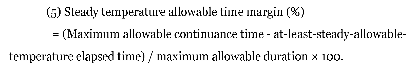
- In this expression, at-least-steady-allowable-temperature elapsed time is an elapsed time shown in
FIG. 7A during which theturbine 4b of theturbocharger 4 does not exceed the maximum allowable temperature but continuously exceeds a steady allowable temperature, and the maximum allowable duration is a limit length of time for which continuous excess over the steady allowable temperature is permitted. - The accordingly-computed surge-pressure margin, rotation-speed margin, and exhaust-temperature margin are each outputted to the
engine ECU 10A as illustrated inFIG. 4 (step T3). Theengine ECU 10A computes a correction amount on the basis of each margin, computes control command values on the basis of the correction amount, and outputs the control command values to the various devices (step E3). Specifically, margins such as a surge-pressure margin and a rotation-speed margin are used mainly in computation of a W/G valve opening-degree command value. An exhaust-temperature margin is used mainly in computation of a control command value of a fuel injection amount. -
FIG. 8 is a diagram for describing computation logics for computing a W/G valve opening-degree command value.FIG. 9 is a diagram for describing computation logics for computing a control command value related to a fuel injection amount. - As illustrated in
FIG. 8 , to compute a W/G valve opening-degree command value, an engine rotation speed and an accelerator signal are inputted into a target boost-pressure map M2 to obtain a target boost pressure. Then, a correction amount computed on the basis of a margin or the like by the following method is subtracted from the obtained target boost pressure to calculate a target boost-pressure corrected value. A feedback control for a boost pressure detected by thepressure sensor 32 is performed to compute a W/G valve opening degree for a difference between a target boost-pressure corrected value and a boost pressure. To the W/G valve opening degree, a value calculated by inputting an engine rotation speed and an accelerator signal to a W/G valve opening-degree map M3 is added, and thereby a W/G valve opening-degree command value is calculated. This computation is performed by a turbo control command value computation part 10A2a of the engine control part 10A2 depicted inFIG. 2 . While the above logic additionally includes a W/G valve opening-degree map M3 as a feed forward circuit to improve responsiveness, the W/G valve opening-degree map M3 may be removed from the above logic to provide a simpler feedback control circuit. - Further, as illustrated in
FIG. 9 , to compute a control command value of a fuel injection amount, firstly, an engine rotation speed, an accelerator signal, and the like are inputted into an air-fuel ratio target value map M4, to calculate a target air-fuel ratio. A feedback control for an air-fuel ratio detected by the air-fuel ratio sensor 31 is performed to compute a fuel injection amount. A correction amount computed on the basis of an exhaust-temperature margin or the like by the following method is subtracted from the calculated fuel injection amount to calculate a control command value for a fuel injection amount. This computation is performed by an engine control part 10A2 depicted inFIG. 2 . -
FIG. 10 is a diagram for describing computation logics for computing a correction amount to be used in computation of a control command value. As shown inFIG. 10 , a correction amount is calculated by, if each of a surge-pressure margin, a rotation-speed margin, and an exhaust-temperature margin is below a margin limit, multiplying a difference between the margin limit and each margin by a gain. As it can be seen inFIG. 10 , a correction amount changes in accordance with the magnitude of a margin, and is calculated to be greater with a decrease in the margin. - Whereas a margin limit may be set as a constant value in advance, a margin limit may be calculated by inputting an engine rotation speed and an accelerator signal to a margin limit map M5 as shown in
FIG. 10 . In this way, it is possible to calculate a suitable margin limit taking account of an operational state of the engine. Further, an accumulated operational time may be inputted to the margin limit map M5 so as to calculate a greater margin limit with an increase in the accumulated operational time. In this way, it is possible to further enhance safety against surging for an engine with a longer accumulated operational time. - Whereas a gain may also be set as a constant value in advance, a gain may be calculated by inputting an engine rotation speed, an accelerator signal, and the like to a gain map M6 as shown in
FIG. 10 , which makes it possible to calculate a suitable gain taking account of an operational state of the engine. - The
control device 10 of the supercharging system of the present embodiment has the above configuration, and computes a target boost-pressure corrected value by using a margin (surge margin), which is a numeral index representing a margin with respect to surging, and correcting a target boost pressure in accordance with the magnitude of the margin. The waste-gate valve 12 (boost-pressure control unit) is controlled so that the boost pressure of the turbocharger 4 (supercharger) reaches a target boost-pressure corrected value. With theabove control device 10 of the supercharging system, the valve opening degree of thewaste-gate valve 12 changes in accordance with the magnitude of the margin. Thus, it is possible to prevent surging in advance while reducing rapid fluctuation of a boost pressure, as compared to a typical case in which the boost-pressure control unit is switched alternatively on the basis of whether an operational point is in the surge region. - Further, the
control device 10 of the supercharging system includes theturbo ECU 10B including a control part and a signal input part provided separately and independently from theengine ECU 10A. Theturbo ECU 10B is different from theengine ECU 10A in that the turbo ECU10B only performs control of theturbocharger 4. Thus, the turbo control part 10B2 of theturbo ECU 10B computes a margin, which makes it possible to compute a margin quickly and accurately. Thus, it is possible to control a boost pressure quickly while avoiding an influence from communication delay which may take place if a margin is computed by theengine ECU 10A. - Further, in the above embodiment, as depicted in
FIG. 8 , a surge-pressure margin is used as a margin for computing a correction amount to correct a target boost pressure, which makes it possible to control thewaste-gate valve 12 accurately while preventing surging securely. - Further, in the above embodiment, a margin may include a rotation-speed margin in addition to a surge-pressure margin. For instance, the smaller one of a surge-pressure margin or a rotation-speed margin may be used as a margin. In this way, it is possible to prevent over-speed of the
turbocharger 4 along with surging. Further, with the rotation-speed margin being defined as the smaller one of the maximum allowable rotation-speed margin or the steady rotation-speed allowable time margin, theturbocharger 4 does not exceed the maximum allowable rotation speed, but is permitted to exceed the steady allowable rotation speed (rated rotation speed of the turbocharger 4) temporarily. In this way, it is possible to perform such a control that maximizes performance of theturbocharger 4. - Further, in the above embodiment, as depicted in
FIG. 9 , a fuel injection amount is corrected by a correction amount computed on the basis of an exhaust-temperature margin. According to this embodiment, correction is performed to reduce a fuel injection amount if an exhaust temperature becomes too high, and thereby an exhaust temperature is reduced. Thus, it is possible to prevent damage to theturbine 4b of theturbocharger 4 due to an excessive increase in an exhaust temperature. - In some embodiments, as illustrated in
FIG. 4 , theturbo ECU 10B has an autonomous-protection function to re-compute a margin (surge-pressure margin, rotation-speed margin) of theturbocharger 4 on the basis of sensor signals related to an operational state of theturbocharger 4 after thewaste-gate valve 12 is controlled on the basis of a W/G valve opening-degree command value (turbo control command value), and to correct the W/G valve opening-degree command value in accordance with the magnitude of the re-computed margin and output the corrected W/G valve opening-degree command value to the waste-gate valve 12 (boost-pressure control unit). - That is, after the
waste-gate valve 12 is controlled in step T4 of the control flow shown inFIG. 4 and an operational state of theturbocharger 4 changes, the above described various sensor signals are read in again (step T5), a surge pressure is computed as shown inFIG. 5 (step T6), and a surge-pressure margin, a rotation-speed margin, and an exhaust-temperature margin are each re-computed as shown inFIGs. 5 to 8 (step T7). Then, as illustrated inFIG. 10 , a margin limit is read in from the margin limit map M5 (step T8), the re-computed margin and the margin limit are compared (step T9), and a W/G valve opening-degree command value is corrected if the re-computed margin is not greater than the margin limit, and the corrected W/G valve opening-degree command corrected value is outputted to the waste-gate valve 12 (step T10). The steps T8 to T10 are performed by a turbo control command value correction computation part 10B2a of the turbo control part 10B2. - In the present embodiment, basically, the
engine ECU 10A computes a W/G valve opening-degree command value corresponding to the above described target boost-pressure corrected value, and the W/G valve opening-degree command value is outputted to thewaste-gate valve 12 to control thewaste-gate valve 12. However, if theengine ECU 10A having complicated control logics and hardware configuration is to control thewaste-gate valve 12 as described above, communication delay of theengine ECU 10A may be a problem, as described above. Thus, with theturbo ECU 10B having the above autonomous-protection function, it is possible to control thewaste-gate valve 12 with theturbo ECU 10B quickly to avoid surging more securely, if theengine ECU 10A cannot control in time or if correction is so insufficient that surging cannot be avoided, for instance. - In the above embodiment, as illustrated in
FIG. 4 , theabove turbo ECU 10B outputs the corrected W/G valve opening-degree command value (turbo control command value) also to theengine ECU 10A, when outputting the corrected W/G valve opening-degree command value to thewaste-gate valve 12. - According to this embodiment, if the
turbo ECU 10B controls thewaste-gate valve 12 autonomously by the autonomous-protection function, the content of the control is transmitted also to theengine ECU 10A. Thus, theengine ECU 10A can control thewaste-gate valve 12 from then on, or control other devices, taking account of the transmitted content of the control. Further, theturbo ECU 10B may autonomously store control of thewaste-gate valve 12, which makes it possible to utilize the stored data for diagnosis of malfunction during maintenance (step E4). -
FIG. 11 is an overall configuration diagram of an engine system to which a control device of a supercharging system according to the second embodiment of the present invention is to be applied. Theengine system 1a of the present embodiment is basically similar to the embodiment illustrated inFIG. 1 in terms of configuration, except that theengine system 1a does not include thebypass channel 14 and thewaste-gate valve 12. Thus, the same component is associated with the same reference numeral and not described in detail. - In the present embodiment, as illustrated in
FIG. 11 , theturbocharger 4 is a variable turbocharger including theturbine 4b driven to rotate by exhaust energy of exhaust gas discharged from theengine 6, thecompressor 4a driven coaxially with theturbine 4b, and avariable control mechanism 4d for controlling a flow of exhaust gas that flows into theturbine 4b. Thevariable control mechanism 4d is adjusted to control a flow of exhaust gas flowing into theturbine 4b, and thereby the boost pressure of theturbocharger 4 is controlled. - In other words, in the present embodiment, the
variable control mechanism 4d corresponds to a boost-pressure control unit which controls a boost pressure of intake air compressed by thecompressor 4a. Theabove turbocharger 4, for instance, includes a variable-displacement type turbocharger equipped with avariable nozzle mechanism 4d including a plurality of nozzle vanes disposed rotatably on the outer periphery of theturbine 4b. - According to the above embodiment, the
variable control mechanism 4d, which is a boost-pressure control unit, is adjusted to control a flow of exhaust gas flowing into theturbine 4b to control a boost pressure of theturbocharger 4, which makes it possible to prevent surging in advance while suppressing rapid fluctuation of a boost pressure. -
FIG. 12 is an overall configuration diagram of an engine system to which a control system of a supercharging system according to the third embodiment of the present invention is to be applied. Theengine system 1b of the present embodiment is basically similar to the embodiment illustrated inFIG. 1 in terms of configuration, except for the two-stage turbo-charging system including two turbochargers, a high-pressure stage turbocharger 4A and a low-pressure stage turbocharger 4B. Thus, the same component is associated with the same reference numeral and not described in detail. - In the present embodiment, as illustrated in
FIG. 12 , the supercharger for compressing intake air to be supplied to theengine 6 includes the high-pressure stage turbocharger 4A and the low-pressure stage turbocharger 4B. The high-pressure stage turbocharger 4A includes a high-pressure stage turbine 4Ab disposed in theexhaust duct 5 of theengine 6 and driven to rotate by exhaust energy from theengine 6 and a high-pressure stage compressor 4Aa disposed in theintake duct 3 of theengine 6 and driven coaxially with the high-pressure stage turbine 4Ab. The low-pressure stage turbocharger 4B includes a low-pressure stage turbine 4Bb disposed in theexhaust duct 5 and on the downstream side of the high-pressure stage turbine 4Ab and a low-pressure stage compressor 4Ba disposed in theintake duct 3 and on the upstream side of the high-pressure stage compressor 4Aa and driven coaxially with the low-pressure stage turbine 4Bb. A high-pressurestage bypass channel 14A that bypasses the high-pressure stage turbine 4Ab and a low-pressurestage bypass channel 14B that bypasses the low-pressure stage turbine 4Bb are connected to theexhaust duct 5 of theengine 6. A high-pressurestage waste-gate valve 12A is disposed in the high-pressurestage bypass channel 14A, and a low-pressurestage waste-gate valve 12B is disposed in the low-pressurestage bypass channel 14B. The above describedcontrol device 10 adjusts the valve opening degrees of the high-pressurestage waste-gate valve 12A and the low-pressurestage waste-gate valve 12B individually, thereby controlling the boost pressures of the high-pressure stage turbocharger 4A and the low-pressure stage turbocharger 4B individually. That is, in the present embodiment, each of the high-pressurestage waste-gate valve 12A and the low-pressurestage waste-gate valve 12B corresponds to a boost-pressure control unit of the present invention. - Next, a method to control boost pressures of the high-
pressure stage turbocharger 4A and the low-pressure stage turbocharger 4B will be described on the basis ofFIGs. 13 to 15 .FIG. 13 is a two-dimensional map related to a control flag, where x-axis is an engine rotation speed and y-axis is a load.FIG. 14 is a diagram corresponding toFIG. 13 , for describing operation of two waste-gate valves and a flow of exhaust gas. The arrow inFIG. 14 indicates a flow direction of exhaust gas. - As shown in
FIG. 13 , the twowaste-gate valves stage bypass channel 14A and the low-pressurestage bypass channel 14B but flows into the high-pressure stage turbine 4Ab and the low-pressure stage turbine 4Bb through theexhaust duct 5, as illustrated inFIG. 14A . The high-pressure stage turbine 4Ab and the low-pressure stage turbine 4Bb are driven to rotate, and the high-pressure stage compressor 4Aa and the low-pressure stage compressor 4Ba are driven coaxially in association. As a result, intake air to be supplied to theengine 6 is supercharged. - If an engine rotation speed increases to enter a mid-speed region (b), the boost pressure of the high-
pressure stage compressor 4A becomes particularly high, which raises a risk of surging. Thus, in the mid-speed region (b), as illustrated inFIG. 14B , the valve opening degree of the high-pressurestage waste-gate valve 12A is adjusted to reduce a flow rate of exhaust gas flowing through the high-pressure stage turbine 4Ab, and the boost pressure of the high-pressure stage compressor 4Aa is controlled. Meanwhile, the boost pressure of the low-pressure stage compressor 4Ba is lower than the boost pressure of the high-pressure stage compressor 4A and surging may not occur. Thus, the low-pressurestage waste-gate valve 12B is controlled to be kept in a fully-closed state. - If the engine rotation speed increases further to enter a high-speed region (c), the high-pressure
stage waste-gate valve 12A is controlled to be fully open, so that exhaust gas does not flow into the high-pressure stage turbine 4Ab. Further, in the high-speed region, the boost pressure of the low-pressure stage compressor 4B also increases, which raises a risk of surging. Thus, in the high-speed region (c), the valve opening degree of the low-pressurestage waste-gate valve 12B is adjusted to reduce a flow rate of exhaust gas flowing through the low-pressure stage turbine 4Bb, and the boost pressure of the low-pressure stage compressor 4Ba is controlled. -
FIG. 15 is a diagram for describing computation logics for computing two W/G valve opening-degree command values, corresponding toFIG. 8 of the first embodiment. As shown inFIG. 15 , firstly, an engine rotation speed and an accelerator signal are inputted into the target boost-pressure map M2 to calculate a target boost pressure. Then, a correction amount computed on the basis of a margin or the like by the above-described method is subtracted from the calculated target boost pressure to calculate a target boost-pressure corrected value. A feedback control for a boost pressure detected by thepressure sensor 32 is performed to compute a W/G valve opening degree for a difference between a target boost-pressure corrected value and a boost pressure for each of the high-pressurestage waste-gate valve 12A and the low-pressurestage waste-gate valve 12B. Herein, an engine rotation speed and an accelerator signal are inputted into a control flag map M5 shown inFIG. 13 to determine which of the above operational regions (a), (b), and (c) corresponds to an operational state of theengine 6, and a result is outputted as a control flag. A W/G valve opening degree is computed in accordance with this control flag, so as to correspond to the content of a boost-pressure control in an operational state shown inFIG. 14 . For instance, if a control flag (a) is outputted, the W/G valve opening degrees of the high-pressurestage waste-gate valve 12A and the low-pressurestage waste-gate valve 12B are computed to be fully closed. If a control flag (b) is outputted, the W/G valve opening degree of the low-pressurestage waste-gate valve 12B is computed to be fully closed, and the W/G valve opening degree of the high-pressurestage waste-gate valve 12A is computed so that the boost pressure of the high-pressure stage turbocharger 4A reaches the target boost pressure. If a control flag (c) is outputted, the W/G valve opening degree of the high-pressurestage waste-gate valve 12A is computed to be fully open, and the W/G valve opening degree of the low-pressurestage waste-gate valve 12B is computed so that the boost pressure of the high-pressure stage turbocharger 4A reaches the target boost pressure. To the computed W/G valve opening degrees, values calculated by inputting an engine rotation speed and an accelerator signal to W/G valve opening-degree maps M3A, M3B are added, and thereby a W/G valve opening-degree command value is calculated for each of the high-pressurestage waste-gate valve 12A and the low-pressurestage waste-gate valve 12B. - According to the present embodiment, in a two-stage supercharging system including the high-
pressure stage turbocharger 4A and the low-pressure stage turbocharger 4B, the valve opening degree of the high-pressurestage waste-gate valve 12A being the boost-pressure control unit for the high-pressure stage turbocharger 4A and the valve opening degree of the low-pressurestage waste-gate valve 12B being the boost-pressure control unit for the low-pressure stage turbocharger 4B are adjusted, and thereby the boost pressures of the high-pressure stage turbocharger 4A and the low-pressure stage turbocharger 4B are controlled, which makes it possible to prevent occurrence of surging in advance while suppressing rapid fluctuation of the boost pressures. -
FIG. 16 is an overall configuration diagram of an engine system to which a control device of a supercharging system according to the fourth embodiment of the present invention is to be applied. Theengine system 1c of the present embodiment is basically similar to the embodiment illustrated inFIG. 1 in terms of configuration, except for the two-stage turbo-charging system including two turbochargers, theturbocharger 4A and anelectric turbocharger 4C. Thus, the same component is associated with the same reference numeral and not described in detail. - In the present embodiment, as illustrated in
FIG. 16 , a turbocharger for compressing intake air to be supplied to theengine 6 includes theturbocharger 4A and theelectric turbocharger 4C. Theturbocharger 4A includes the turbine 4Ab disposed in theexhaust duct 5 of theengine 6 and driven to rotate by exhaust energy from theengine 6, and the compressor 4Aa disposed in theintake duct 3 of theengine 6 and driven coaxially with the turbine 4Ab. Theelectric turbocharger 4C includes an electric compressor 4Ca disposed upstream of the compressor 4Aa of theturbocharger 4A, a motor 4Cd for driving the electric compressor 4Ca to rotate, and an inverter 4Ce (rotation-speed control unit) which controls a rotation speed of the motor 4Cd. Thebypass channel 14 bypassing the turbine 4Ab is connected to theexhaust duct 5 of theengine 6, and thewaste-gate valve 12 is disposed in thebypass channel 14. The boost pressure of theturbocharger 4A is controlled by adjusting the valve opening degree of thewaste-gate valve 12. Further, the rotation speed of the motor 4Cd is controlled by the inverter 4Ce to control the boost pressure of theelectric turbocharger 4C. That is, in the present embodiment, each of thewaste-gate valve 12 and the inverter 4Ce corresponds to a boost-pressure control unit of the present invention. -
FIG. 17 is a control flowchart of a boost-pressure control unit according to the fourth embodiment, corresponding toFIG. 4 of the first embodiment. Thus, the same component also shown inFIG. 4 is associated with the same reference numeral and not described in detail. - In the control flow of the present embodiment, in step E3, a motor rotation-speed command value, which is a control command value for the inverter 4Ce, is computed in addition to a W/G valve opening-degree command value (turbo control command value) for the
waste-gate valve 12. The computed motor rotation-speed command value is outputted to theturbo ECU 10B, and theturbo ECU 10B controls the output of the inverter 4Ce (step T4'), which differentiates the present embodiment from the above described first embodiment. - Further, the margin re-computed in step T9 is compared with a margin limit, and if the recomputed margin is not greater than a margin limit, not only the W/G valve opening-degree command value but also the motor rotation-speed command value is corrected, and the corrected motor rotation-speed command corrected value is outputted to the inverter 4Ce (step T10'), which differentiates the present embodiment from the above described first embodiment.
- According to the present embodiment, in a two-stage supercharging system including the
turbocharger 4A and theelectric turbocharger 4C, the valve opening degree of thewaste-gate valve 12 being the boost-pressure control unit for theturbocharger 4A is adjusted, and the rotation speed of the motor 4Cd is controlled with the inverter 4Ce being the boost-pressure control unit for theelectric turbocharger 4C, and thereby the boost pressure of each of theturbocharger 4A and theelectric turbocharger 4C is controlled, which makes it possible to prevent occurrence of surging in advance while suppressing rapid fluctuation of the boost pressure. In the above embodiment, theelectric turbocharger 4C is disposed on a low-pressure stage side. However, the positions of theturbocharger 4A and theelectric turbocharger 4C may be switched so that theelectric turbocharger 4C is disposed on a high-pressure stage side. - Next, the fifth embodiment of the present invention will be described with reference to
FIGs. 18 to 21 .FIG. 18 is a block diagram for describing functions of an engine ECU according to the fifth embodiment.FIG. 19 is a block diagram for describing functions of a turbo ECU according to the fifth embodiment. The overall configuration of an engine system according to the present embodiment is the same as that in the first embodiment depicted inFIG. 1 , and thus not described again in detail. - The
engine ECU 10A of the present embodiment is different from the first embodiment in that, as illustrated inFIG. 18 , the engine control part 10A2 does not compute a W/G valve opening-degree command value (turbo control command value). In the present embodiment, theengine ECU 10A computes a target boost pressure, and the computed target boost pressure is outputted to theturbo ECU 10B. As illustrated inFIG. 19 , theturbo ECU 10B corrects the target boost pressure on the basis of a margin computed by the turbo control part 10B2 to compute a target boost-pressure corrected value, and also computes a W/G valve opening-degree command value corresponding to the target boost-pressure corrected value. The computed W/G valve opening-degree command value (turbo control command value) is outputted to thewaste-gate valve 12. -
FIG. 20 is a control flowchart of a boost-pressure control unit according to the fifth embodiment. - In the present embodiment, as illustrated in
FIG. 20 , theengine ECU 10A reads in the above described various sensor signals (step E1), and then computes control command values for the various devices, such as a fuel-injection amount, an ignition timing, a throttle opening, and a boost pressure, and also computes a target boost pressure (step E2). In parallel to the control by theengine ECU 10A, theturbo ECU 10B reads in the above described various sensor signals (step T1), computes a surge pressure (step T2), and computes a margin such as a surge pressure margin, a rotation-speed margin, and an exhaust-temperature margin (step T3). Theturbo ECU 10B corrects the target boost pressure on the basis of a margin to compute a target boost-pressure corrected value, and also computes a W/G valve opening-degree command value corresponding to the target boost-pressure corrected value. The computed target boost-pressure corrected value is also outputted to theengine ECU 10A. Theturbo ECU 10B performs a feedback control so as to match the valve opening degree of thewaste-gate valve 12 to the W/G valve opening-degree command value (step T4). -
FIG. 21 is a diagram for describing computation logics for computing a W/G valve opening-degree command value. - In the present embodiment, as illustrated in
FIG. 21 , to compute a W/G valve opening-degree command value, a correction amount computed on the basis of a margin or the like by the above-described method is subtracted from the target boost pressure computed by theengine ECU 10A to calculate a target boost-pressure corrected value. A feedback control for a boost pressure detected by thepressure sensor 32 is performed to compute a W/G valve opening degree for a difference between a target boost-pressure corrected value and a boost pressure. To the W/G valve opening degree, a value calculated by inputting an engine rotation speed and an accelerator signal to a W/G valve opening-degree map M3 is added, and thereby a W/G valve opening-degree command value is calculated. This computation is performed by a turbo control command value computation part 10B2b of the turbo control part 10B2 illustrated inFIG. 19 . - According to this embodiment, basically, a target boost-pressure corrected value is computed by the
turbo ECU 10B, and a W/G valve opening-degree command value (turbo control command value) corresponding to the target boost-pressure corrected value is computed, and the W/G valve opening-degree command value is outputted to thewaste-gate valve 12. Specifically, theturbo ECU 10B itself performs the entire control of the boost-pressure control unit, and does not need to communicate with theengine ECU 10A, which makes it possible to control the boost-pressure control unit quickly while avoiding an influence from communication delay of theengine ECU 10A. - In the above embodiment, as illustrated in
FIG. 20 , theturbo ECU 10B outputs the computed target boost-pressure corrected value also to theengine ECU 10A. - According to this embodiment, the
engine ECU 10A can reflect the target boost-pressure corrected value computed by theturbo ECU 10B to control the boost-pressure control unit from then on, or to control other devices. - Next, the sixth embodiment of the present invention will be described with reference to
FIGs. 22 to 25 .FIG. 22 is a block diagram for describing functions of an engine ECU according to the sixth embodiment.FIG. 23 is a block diagram for describing functions of a turbo ECU according to the sixth embodiment. The overall configuration of an engine system according to the present embodiment is the same as that in the first embodiment depicted inFIG. 1 , and thus not described again in detail. - The
engine ECU 10A of the present embodiment is different from the first embodiment in that, as illustrated inFIG. 22 , the engine control part 10A2 does not compute a W/G valve opening-degree command value (turbo control command value). In the present embodiment, theengine ECU 10A computes a target boost pressure, and the computed target boost pressure is outputted to theturbo ECU 10B. This is similar to the above described fifth embodiment. - In the present embodiment, as illustrated in
FIG. 23 , the turbo control part 10B2 does not compute a margin as described above. Instead, the turbo control part 10B2 computes a surge pressure which is a limit pressure at which surging occurs, on the basis of sensor signals such as a boost pressure and an intake flow rate inputted into the turbo signal input part 10b1. A pressure value corresponding to a predetermined margin limit is subtracted from the computed surge pressure to calculate an upper limit pressure. The upper limit pressure and the target boost pressure are compared, and if the target boost pressure is larger than the upper limit pressure, the target boost pressure is corrected so as to obtain a target boost pressure corrected value equal to the upper limit pressure. - The margin limit is set as a constant value that does not change with time in accordance with a change in an operational state (engine rotation speed or accelerator signal) of the engine, such as 5%, 10%, and 15%. Thus, it is no longer necessary to compute a margin limit repetitively with time in accordance with a change in an operational state of the engine, unlike the above described embodiments. Thus, it is possible to simplify computation logics of the
turbo controller 10B. -
FIG. 24 is a control flowchart of a boost-pressure control unit according to the sixth embodiment. - In the present embodiment, as illustrated in
FIG. 24 , theengine ECU 10A reads in the above described various sensor signals (step E1), and then computes control command values for the various devices, such as a fuel-injection amount, an ignition timing, a throttle opening, and a boost pressure, and also computes a target boost pressure (step E2). In parallel to this control by theengine ECU 10A, theturbo ECU 10B reads in the above described various sensor signals (step T1), computes a surge pressure (step T2), and computes an upper limit pressure from the surge pressure and a predetermined margin limit (step T3). The upper limit pressure and the target boost pressure are compared (step T4), and if the upper limit pressure is greater than the target boost pressure (YES in step T4), the target boost pressure is not corrected (i.e., "target boost pressure" is set to be equal to "target boost pressure corrected value"), and a W/G valve opening-degree command value corresponding to the target boost pressure corrected value (target boost pressure) is computed (step T6). If the upper limit pressure is not greater than the target boost pressure (NO in step T4), a target boost-pressure corrected value is computed so that the target boost-pressure corrected value equals to the upper limit pressure (step T5), and a W/G valve opening-degree command value corresponding to the target boost-pressure corrected value (upper limit pressure) is computed (step T6). Further, an indication (correction flag) of having corrected the target boost pressure for matching the target boost-pressure corrected value to the upper limit pressure and the target boost-pressure corrected value are transmitted to theengine ECU 10A. -
FIG. 25 is a diagram for describing computation logics for computing a W/G valve opening-degree command value. - In the present embodiment, as illustrated in
FIG. 25 , to compute a W/G valve opening-degree command value, firstly, an intake flow rate and a W/G valve opening degree are inputted to a surge-pressure map M1 to calculate a surge pressure ratio, and the surge pressure ratio is multiplied by an atmospheric pressure to calculate a surge pressure. A pressure value corresponding to a predetermined margin limit is subtracted from the surge pressure to compute an upper limit pressure. Herein, a pressure value corresponding to a margin limit is calculated by multiplying the computed surge pressure by a margin limit. The accordingly calculated upper limit pressure and the target boost pressure computed by theengine ECU 10A are compared, and the smaller one is outputted as a target boost-pressure corrected value. A feedback control for a boost pressure detected by thepressure sensor 32 is performed to compute a W/G valve opening degree for a difference between a target boost-pressure corrected value and a boost pressure. - According to this embodiment, similarly to the above described fifth embodiment, a target boost-pressure corrected value is computed by the
turbo ECU 10B, and a W/G valve opening-degree command value (turbo control command value) corresponding to the target boost-pressure corrected value is computed, and the W/G valve opening-degree command value is outputted to thewaste-gate valve 12. Specifically, theturbo ECU 10B itself performs the entire control of the boost-pressure control unit, and does not need to communicate with theengine ECU 10A, which makes it possible to control the boost-pressure control unit quickly while avoiding an influence from communication delay of theengine ECU 10A. - Further, in the present embodiment, the upper limit pressure and the target boost pressure are compared, and if the target boost pressure is larger than the upper limit pressure, the target boost pressure is corrected so as to match the target boost pressure corrected value with the upper limit pressure, and thus the computation logics for correcting a target boost pressure are simple. Accordingly, it is possible to simplify the computation logics of the
turbo controller 10B even compared to those in the fifth embodiment, and to compute a turbo control command value in an instant, which makes it possible to improve control responsiveness of a boost-pressure control unit such as the W/G valve and the VG actuator. - In some embodiments, the
turbo controller 10B stores a plurality of margin limit values defined as constant values in advance. The plurality of margin limit values are each associated with corresponding one of a plurality of preset operation modes, and a margin limit corresponding to a selected operation mode is selected. - For instance, three margin limits are set in advance, including: the first margin limit (e.g. 10%) corresponding to a normal mode; the second margin limit (e.g. 5%) corresponding to a high-response mode and smaller than the first margin limit; and the third margin limit (e.g. 15%) corresponding to a safety mode and larger than the first margin limit. A margin limit corresponding to a selected operation mode may be selected in response to switching of the operation modes by a driver or the like.
- According to this embodiment, it is possible to provide a variable margin limit without making the computation logics of the
turbo controller 10B more complicated. - The embodiments of the present invention have been described above. However, the present invention is not limited thereto. For instance, various modifications may be applied as long as they do not depart from the object of the present invention.
- At least one embodiment of the present invention can be suitably used as a control device for a supercharging system for supplying compressed intake air to an engine for an automobile, a ship, or an industrial use.
-
- 1, 1a, 1b, 1c
- Engine system
- 2
- Air cleaner
- 3
- Intake duct
- 4
- Turbocharger (supercharger)
- 4A
- High-pressure stage turbocharger (supercharger)
- 4B
- Low-pressure stage turbocharger (supercharger)
- 4C
- Electric turbocharger (supercharger)
- 4a, 4Aa, 4Ba
- Compressor
- 4Ca
- Electric compressor
- 4b, 4Ab, 4Bb
- Turbine
- 4Cd
- Motor
- 4Ce
- Inverter (rotation-speed control unit, boost-pressure control unit)
- 4c
- Rotor
- 4d
- Variable control mechanism (boost-pressure control unit)
- 5
- Exhaust duct
- 6
- Engine
- 6a
- Combustion chamber
- 6b
- Cylinder liner
- 6c
- Piston
- 7
- Throttle valve
- 8
- Injector
- 9a
- Intake port
- 9b
- Exhaust port
- 10
- Control device
- 10A
- Engine ECU (engine controller)
- 10A1
- Engine-signal input part
- 10A2
- Engine control part
- 10A3
- Engine-signal output part
- 10B
- Turbo ECU (turbo controller)
- 10b1
- Turbo signal input part
- 10B2
- Turbo control part
- 10B3
- Turbo signal output part
- 11
- Spark plug
- 12, 12A, 12B
- Waste-gate valve (boost-pressure control unit)
- 14
- Bypass channel
- 14A
- High-pressure stage bypass channel
- 14B
- Low-pressure stage bypass channel
- 19
- Intercooler
- 30
- Rotation-speed sensor
- 31
- Air-fuel ratio sensor
- 32
- Pressure sensor
- 33
- Air-flow meter
- 34
- Exhaust-temperature sensor
- 35
- Turbo rotation-speed sensor
Claims (13)
- A control device for a supercharging system for supplying compressed intake air to an engine, the supercharging system comprising a supercharger configured to compress intake air to be supplied to the engine, a boost-pressure control unit configured to control a boost pressure of the supercharger, and a control device configured to control the boost-pressure control unit, and the control device comprising:an engine controller comprising an engine signal input part to which various sensor signals related to an operational state of the engine are to be inputted, and an engine control part configured to control an operational state of the engine and to compute a target boost pressure of the supercharger on the basis of the sensor signals inputted into the engine signal input part; anda turbo controller comprising a turbo signal input part to which at least sensor signals related to an operational state of the supercharger are to be inputted from among the various sensor signals related to an operational state of the engine, and a turbo control part configured to compute a margin of the supercharger on the basis of the sensor signals inputted to the turbo signal input part, the turbo controller comprising a control part and a signal input part provided separately and independently from the engine controller,wherein the control device is configured to compute a target boost-pressure corrected value by correcting the target boost pressure in accordance with a magnitude of the margin computed by the turbo control part, and to control the boost-pressure control unit so that the boost pressure of the supercharger reaches the target boost-pressure corrected value.
- The control device for a supercharging system according to claim 1,
wherein the engine controller is configured to compute the target boost-pressure corrected value by correcting the target boost pressure in accordance with the magnitude of the margin, compute a turbo control command value corresponding to the target boost-pressure corrected value, and output the computed turbo control command value to the boost-pressure control unit via the turbo controller, and
wherein the turbo controller has an autonomous protection function to re-compute a margin of the supercharger on the basis of sensor signals related to an operational state of the supercharger after the boost-pressure control unit is controlled on the basis of the turbo control command value, correct the turbo control command value in accordance with a magnitude of the re-computed margin, and output the corrected turbo control command value to the boost-pressure control unit. - The control device for a supercharging system according to claim 2,
wherein the turbo controller is configured to output the corrected turbo control command value also to the engine controller when outputting the corrected turbo control command value to the boost-pressure control unit. - The control device for a supercharging system according to claim 1,
wherein the engine controller is configured to output the target boost pressure computed by the engine control part to the turbo controller, and
wherein the turbo controller is configured to compute a target boost-pressure corrected value by correcting the target boost pressure on the basis of the margin computed by the turbo control part, compute a turbo control command value corresponding to the target boost-pressure corrected value, and output the computed turbo control command value to the boost-pressure control unit. - The control device for a supercharging system according to claim 4,
wherein the turbo controller is configured to output the computed target boost-pressure corrected value also to the engine controller. - The control device for a supercharging system according to claim 1,
wherein the margin includes a surge-pressure margin which is a ratio of a difference between a surge pressure and a boost pressure to the surge pressure, where the surge pressure is a limit pressure at which surging occurs. - The control device for a supercharging system according to claim 6,
wherein the margin includes a rotation-speed margin in addition to the surge-pressure margin, the rotation-speed margin being defined as the smaller one of:a maximum allowable rotation-speed margin which is a ratio of a difference between a maximum allowable rotation speed of the supercharger and a rotation speed of the supercharger to the maximum allowable rotation speed; ora steady rotation-speed allowable time margin which is a ratio of a difference between a maximum allowable duration and an elapsed time of continuous excess over a steady allowable rotation speed to the maximum allowable duration, where the steady allowable rotation speed is a rotation speed of the supercharger set to be lower than the maximum allowable rotation speed, and the maximum allowable duration is a limit length of time for which the rotation speed of the supercharger is allowed to exceed the steady allowable rotation speed continuously. - The control device for a supercharging system according to claim 1,
wherein the engine controller is configured to correct a fuel injection amount computed on the basis of the sensor signals inputted to the engine signal input part in accordance with a magnitude of an exhaust-temperature margin defined as the smaller one of:a maximum allowable temperature margin which is a ratio of a difference between a maximum allowable temperature of the supercharger and a temperature of exhaust gas flowing through an exhaust duct of the engine to the maximum allowable temperature; ora steady temperature allowable time margin which is a ratio of a difference between a maximum allowable duration and an elapsed time of continuous excess over a steady allowable temperature to the maximum allowable duration, where the steady allowable temperature is a temperature of the supercharger set to be lower than the maximum allowable temperature, and the maximum allowable duration is a limit length of time for which the temperature of the exhaust gas is allowed to exceed the steady allowable temperature continuously. - The control device for a supercharging system according to claim 1,
wherein the supercharger comprises a turbocharger comprising a turbine disposed in an exhaust duct of the engine and driven to rotate by exhaust energy of exhaust gas discharged from the engine, and a compressor disposed in an intake duct of the engine and driven to rotate coaxially with the turbine, and
wherein a bypass channel bypassing the turbine is connected to the exhaust duct of the engine, a waste-gate valve is disposed in the bypass channel, and the boost pressure of the supercharger is controlled by adjusting a valve opening degree of the waste-gate valve. - The control device for a supercharging system according to claim 1,
wherein the supercharger comprises a variable turbocharger comprising a turbine driven to rotate by exhaust energy of exhaust gas discharged from the engine, a compressor driven to rotate coaxially with the turbine, and a variable control mechanism configured to control a flow of the exhaust gas flowing into the turbine, and
wherein the boost pressure of the supercharger is controlled by controlling the flow of the exhaust gas flowing into the turbine by adjusting the variable control mechanism. - The control device for a supercharging system according to claim 1,
wherein the supercharger comprises:a high-pressure stage turbocharger comprising a high-pressure stage turbine disposed in an exhaust duct of the engine and driven to rotate by exhaust energy of exhaust gas discharged from the engine, and a high-pressure stage compressor disposed in an intake duct of the engine and driven to rotate coaxially with the high-pressure stage turbine; anda low-pressure stage turbocharger comprising a low-pressure stage turbine disposed in the exhaust duct at a downstream side of the high-pressure stage turbine, and a low-pressure stage compressor disposed in the intake duct at an upstream side of the high-pressure stage compressor and driven to rotate coaxially with the low-pressure stage turbine,wherein a high-pressure stage bypass channel bypassing the high-pressure stage turbine and a low-pressure stage bypass channel bypassing the low-pressure stage turbine are connected to the exhaust duct of the engine, a high-pressure stage waste-gate valve is disposed in the high-pressure stage bypass channel, and a low-pressure stage waste-gate valve is disposed in the low-pressure stage bypass channel, and
wherein boost pressures of the high-pressure stage turbocharger and the low-pressure stage turbocharger are controlled individually by adjusting respective valve opening degrees of the high-pressure stage waste-gate valve and the low-pressure stage waste-gate valve. - The control device for a supercharging system according to claim 1,
wherein the supercharger comprises:a turbocharger comprising a turbine disposed in an exhaust duct of the engine and driven to rotate by exhaust energy of exhaust gas discharged from the engine, and a compressor disposed in an intake duct of the engine and driven to rotate coaxially with the turbine; andan electric turbocharger comprising an electric compressor disposed upstream or downstream of the compressor of the turbocharger, a motor configured to drive the electric compressor to rotate, and a rotation-speed control unit configured to control a rotation speed of the motor,wherein a bypass channel bypassing the turbine is connected to the exhaust duct of the engine, and a waste-gate valve is disposed in the bypass channel, and
wherein the boost pressure of the turbocharger is controlled by adjusting a valve opening degree of the waste-gate valve, and a boost pressure of the electric turbocharger is controlled by controlling the rotation speed of the motor with the rotation-speed control unit. - A control device for a supercharging system for supplying compressed intake air to an engine, the supercharging system comprising a supercharger configured to compress intake air to be supplied to the engine, a boost-pressure control unit configured to control a boost pressure of the supercharger, and a control device configured to control the boost-pressure control unit, and the control device comprising:an engine controller comprising an engine signal input part to which various sensor signals related to an operational state of the engine are to be inputted, an engine control part configured to control an operational state of the engine and to compute a target boost pressure of the supercharger on the basis of the sensor signals inputted into the engine signal input part, and an engine signal output part configured to output the target boost pressure computed by the engine control part; anda turbo controller comprising a turbo signal input part to which at least sensor signals related to an operational state of the supercharger from among the various sensor signals related to an operational state of the engine and the target boost pressure are to be inputted, and a turbo-control part configured to compute a target boost-pressure corrected value by correcting the target boost pressure inputted to the turbo signal input part and compute a turbo control command value corresponding to the target boost-pressure corrected value, and a turbo signal output part configured to output the turbo control command value computed by the turbo control part to the boost-pressure control unit, the turbo controller comprising a control part and a signal input-output part provided separately and independently from the engine controller,wherein the turbo control part is configured tocompute a surge pressure which is a limit pressure at which surging occurs, on the basis of the sensor signals inputted to the turbo signal input part,compute an upper-limit pressure by subtracting a pressure value corresponding to a margin limit value defined in advance as a constant value from the computed surge pressure, andcompare the upper-limit pressure with the target boost pressure and correct the target boost pressure so that the target boost-pressure corrected value coincides with the upper-limit pressure if the target boost pressure is larger than the upper-limit pressure.
Applications Claiming Priority (3)
| Application Number | Priority Date | Filing Date | Title |
|---|---|---|---|
| JP2013251250 | 2013-12-04 | ||
| JP2014236571A JP6434285B2 (en) | 2013-12-04 | 2014-11-21 | Control device for supercharging system |
| PCT/JP2014/081723 WO2015083658A1 (en) | 2013-12-04 | 2014-12-01 | Control device for supercharging system |
Publications (3)
| Publication Number | Publication Date |
|---|---|
| EP3078831A1 true EP3078831A1 (en) | 2016-10-12 |
| EP3078831A4 EP3078831A4 (en) | 2017-07-05 |
| EP3078831B1 EP3078831B1 (en) | 2020-06-10 |
Family
ID=53273420
Family Applications (1)
| Application Number | Title | Priority Date | Filing Date |
|---|---|---|---|
| EP14867002.9A Active EP3078831B1 (en) | 2013-12-04 | 2014-12-01 | Control device for supercharging system |
Country Status (5)
| Country | Link |
|---|---|
| US (1) | US10428748B2 (en) |
| EP (1) | EP3078831B1 (en) |
| JP (1) | JP6434285B2 (en) |
| CN (1) | CN105793536B (en) |
| WO (1) | WO2015083658A1 (en) |
Families Citing this family (18)
| Publication number | Priority date | Publication date | Assignee | Title |
|---|---|---|---|---|
| JP6377340B2 (en) * | 2013-12-04 | 2018-08-22 | 三菱重工業株式会社 | Control device for supercharging system |
| JP6077483B2 (en) * | 2014-03-26 | 2017-02-08 | 本田技研工業株式会社 | Control device |
| JP5972951B2 (en) * | 2014-10-28 | 2016-08-17 | 三菱重工業株式会社 | Auxiliary machine control device, control system, supercharger, control method and program |
| JP6610146B2 (en) * | 2015-10-07 | 2019-11-27 | いすゞ自動車株式会社 | Internal combustion engine and control method thereof |
| CN108699966B (en) * | 2016-03-08 | 2021-08-24 | 三菱重工发动机和增压器株式会社 | Surge detection method and surge detection device for supercharger |
| US10677149B2 (en) | 2016-03-08 | 2020-06-09 | Mitsubishi Heavy Industries Engine & Turbocharger, Ltd. | Surge avoidance control method and surge avoidance control device for exhaust turbine turbocharger |
| JP6344438B2 (en) * | 2016-08-05 | 2018-06-20 | トヨタ自動車株式会社 | Control device for internal combustion engine |
| DE102016011305B3 (en) * | 2016-09-19 | 2018-02-15 | Mtu Friedrichshafen Gmbh | Control method for a supercharged internal combustion engine |
| JP6227086B1 (en) * | 2016-10-11 | 2017-11-08 | 三菱電機株式会社 | Control device and control method for internal combustion engine with supercharger |
| US10190483B2 (en) * | 2016-11-23 | 2019-01-29 | GM Global Technology Operations LLC | Method of controlling a pressure ratio in a flow of compressed combustion air |
| JP6848840B2 (en) * | 2017-11-30 | 2021-03-24 | トヨタ自動車株式会社 | Wastegate valve controller |
| CN109854394A (en) * | 2017-11-30 | 2019-06-07 | 中国人民解放军陆军军事交通学院 | Become the double VGT second level adjustable supercharging control methods of height above sea level |
| FR3085441B1 (en) * | 2018-08-29 | 2020-08-21 | Psa Automobiles Sa | METHOD FOR CHECKING THE MAXIMUM BOOSTER PRESSURE OF A BOOSTER COMPRESSOR OF A VEHICLE THERMAL ENGINE |
| US11421582B2 (en) * | 2020-12-02 | 2022-08-23 | Ford Global Technologies, Llc | Method of controlling a turbocharger |
| JP7486904B2 (en) | 2021-01-22 | 2024-05-20 | ダイハツ工業株式会社 | Control device for internal combustion engine |
| CN113864041B (en) * | 2021-09-30 | 2022-08-09 | 上海交通大学 | Electric supercharging-based high back pressure diesel engine power recovery method and implementation device thereof |
| WO2024185676A1 (en) * | 2023-03-08 | 2024-09-12 | 株式会社小松製作所 | Surge avoidance control device, internal combustion engine system, surge avoidance control method, and program |
| CN118088330B (en) * | 2024-04-26 | 2024-07-19 | 潍柴动力股份有限公司 | Supercharger control method and device, electronic equipment and vehicle |
Family Cites Families (89)
| Publication number | Priority date | Publication date | Assignee | Title |
|---|---|---|---|---|
| JPS5853643A (en) | 1981-09-25 | 1983-03-30 | Hitachi Ltd | Control method of two-shaft gas turbine |
| JPS5952139U (en) | 1982-09-30 | 1984-04-05 | 日産ディーゼル工業株式会社 | Turbo compound internal combustion engine |
| JPS6138127U (en) | 1984-08-13 | 1986-03-10 | 三菱重工業株式会社 | pneumatic transport equipment |
| US4798257A (en) | 1985-10-19 | 1989-01-17 | Isuzu Motors Limited | Energy recovery apparatus for turbo compound engine |
| JP2510855B2 (en) | 1986-02-10 | 1996-06-26 | いすゞ自動車株式会社 | Energy recovery device in vehicle |
| JPS62210222A (en) | 1986-03-11 | 1987-09-16 | Toyota Motor Corp | Control method for supercharger associated with variable nozzle |
| JPS6432019A (en) | 1987-07-27 | 1989-02-02 | Hino Motors Ltd | Malfunction detector for supercharged engine |
| JPH01116234A (en) | 1987-10-28 | 1989-05-09 | Isuzu Motors Ltd | Turbo compound engine |
| US5063744A (en) * | 1988-10-06 | 1991-11-12 | Toyota Jidosha Kabushiki Kaisha | Actuator for controlling intake pressure in sequential turbo-system |
| JPH0533688A (en) | 1991-07-31 | 1993-02-09 | Japan Electron Control Syst Co Ltd | Torque-down controller of automatic transmission for vehicle |
| JP3094646B2 (en) | 1992-03-31 | 2000-10-03 | いすゞ自動車株式会社 | Control device for variable capacity turbocharger |
| JPH06323158A (en) | 1993-05-13 | 1994-11-22 | Isuzu Ceramics Kenkyusho:Kk | Turbocompound engine |
| JPH06341325A (en) | 1993-05-31 | 1994-12-13 | Isuzu Motors Ltd | Exhaust gas energy recovering device |
| DE4330368A1 (en) | 1993-09-08 | 1995-03-09 | Bosch Gmbh Robert | Method and device for controlling the drive power output of a vehicle |
| JP3045041B2 (en) | 1995-05-30 | 2000-05-22 | 株式会社日立製作所 | Gas turbine for pressurized fluidized bed combustion plant and method of detecting turbine aging |
| JP3127829B2 (en) | 1996-06-13 | 2001-01-29 | 三菱自動車工業株式会社 | Engine with turbocharger |
| US5873248A (en) * | 1996-06-21 | 1999-02-23 | Caterpillar Inc. | Turbocharger control system |
| JPH10159576A (en) | 1996-11-29 | 1998-06-16 | Aisin Seiki Co Ltd | Control device for turbocharger with dynamo-electric machine |
| DE19750445C1 (en) | 1997-11-14 | 1999-06-24 | Daimler Chrysler Ag | Method for controlling a VTG exhaust gas turbocharger |
| JP3670149B2 (en) | 1998-12-17 | 2005-07-13 | 日野自動車株式会社 | Turbocharger |
| US6209390B1 (en) | 1999-05-14 | 2001-04-03 | Larue Gerald Duane | Turbocharger fatigue life monitor |
| JP3680639B2 (en) * | 1999-06-15 | 2005-08-10 | 日産自動車株式会社 | Engine control device |
| JP2001342840A (en) * | 2000-05-30 | 2001-12-14 | Mitsubishi Motors Corp | Control device of internal combustion engine having supercharger |
| JP2002188474A (en) | 2000-12-15 | 2002-07-05 | Mazda Motor Corp | Control device for diesel engine with turbosupercharger |
| US6705084B2 (en) * | 2001-07-03 | 2004-03-16 | Honeywell International Inc. | Control system for electric assisted turbocharger |
| US6681573B2 (en) * | 2002-02-05 | 2004-01-27 | Honeywell International Inc | Methods and systems for variable geometry turbocharger control |
| JP2003227362A (en) | 2002-02-07 | 2003-08-15 | Toyota Motor Corp | Operation control device for internal combustion engine |
| DE10207469A1 (en) | 2002-02-21 | 2003-09-18 | Audi Ag | Method and device for checking the function of a bypass element of a boost pressure control of a turbo engine |
| JP2003269183A (en) | 2002-03-12 | 2003-09-25 | Ishikawajima Harima Heavy Ind Co Ltd | Operation state monitoring device of supercharger of diesel engine |
| JP2004027897A (en) | 2002-06-24 | 2004-01-29 | Nissan Motor Co Ltd | Controlling device of turbo supercharger |
| US6983659B2 (en) | 2003-01-22 | 2006-01-10 | Mitsubishi Heavy Industries, Ltd. | Turbine blade creep life evaluating method, turbine blade creep elongation strain measuring apparatus, and turbine blade |
| JP2004251203A (en) | 2003-02-20 | 2004-09-09 | Jidosha Denki Kogyo Co Ltd | Nozzle vane driving control device for variable nozzle type turbo charger |
| DE10310221B4 (en) | 2003-03-08 | 2006-11-23 | Daimlerchrysler Ag | Method for limiting a boost pressure |
| JP4023421B2 (en) | 2003-09-10 | 2007-12-19 | トヨタ自動車株式会社 | Control device for internal combustion engine |
| JP2005155384A (en) | 2003-11-21 | 2005-06-16 | Toyota Motor Corp | Failure diagnosis device for internal combustion engine provided with turbocharger |
| US7104120B2 (en) | 2004-03-02 | 2006-09-12 | Caterpillar Inc. | Method and system of determining life of turbocharger |
| JP4209350B2 (en) | 2004-03-11 | 2009-01-14 | トヨタ自動車株式会社 | Supercharger control device |
| JP3945496B2 (en) | 2004-06-09 | 2007-07-18 | いすゞ自動車株式会社 | Turbocharger fatigue failure diagnosis method and apparatus |
| DE102004038156A1 (en) | 2004-08-06 | 2006-02-23 | Mtu Friedrichshafen Gmbh | Device and method for controlling an exhaust gas turbocharger with variable turbine geometry |
| JP2006063873A (en) | 2004-08-26 | 2006-03-09 | Suzuki Motor Corp | Control system for engine provided with supercharger |
| JP4415912B2 (en) | 2004-10-06 | 2010-02-17 | 株式会社デンソー | Engine control system |
| JP4479488B2 (en) | 2004-12-01 | 2010-06-09 | 株式会社デンソー | Exhaust power generator |
| JP4483584B2 (en) | 2005-01-06 | 2010-06-16 | トヨタ自動車株式会社 | Supercharging system for internal combustion engines |
| JP2006207506A (en) | 2005-01-28 | 2006-08-10 | Toyota Motor Corp | Supercharging control device |
| KR100749620B1 (en) * | 2005-03-02 | 2007-08-14 | 가부시키가이샤 덴소 | Controller for internal combustion engine with supercharger |
| JP4475585B2 (en) | 2005-03-03 | 2010-06-09 | 関西電力株式会社 | Method and apparatus for filling ice slurry into cooling panel |
| JP4475584B2 (en) | 2005-03-03 | 2010-06-09 | 関西電力株式会社 | Thermal storage type cold storage vehicle or cold storage and thermal storage material supply system |
| US7469177B2 (en) | 2005-06-17 | 2008-12-23 | Honeywell International Inc. | Distributed control architecture for powertrains |
| JP4557830B2 (en) | 2005-07-22 | 2010-10-06 | シャープ株式会社 | refrigerator |
| GB2428844A (en) | 2005-07-30 | 2007-02-07 | Siemens Ind Turbomachinery Ltd | Rotating machines |
| EP1749990B1 (en) * | 2005-08-03 | 2013-07-03 | Honda Motor Co., Ltd. | An engine system with a supercharger |
| JP4433051B2 (en) | 2005-11-11 | 2010-03-17 | トヨタ自動車株式会社 | Control device for internal combustion engine |
| EP2292915B1 (en) * | 2005-12-20 | 2013-07-24 | BorgWarner, Inc. | Controlling exhaust gas recirculation in turbocharged engine systems |
| JP2007206007A (en) | 2006-02-06 | 2007-08-16 | Mitsubishi Heavy Ind Ltd | Method for monitoring status of component and apparatus thereof |
| JP4915144B2 (en) | 2006-06-07 | 2012-04-11 | トヨタ自動車株式会社 | Power generation control device for vehicle |
| JP4306703B2 (en) * | 2006-08-10 | 2009-08-05 | トヨタ自動車株式会社 | Control device for an internal combustion engine with a supercharger |
| JP2008050981A (en) | 2006-08-23 | 2008-03-06 | Denso Corp | Control device for turbocharger with electric motor |
| WO2008075593A1 (en) | 2006-12-19 | 2008-06-26 | Toyota Jidosha Kabushiki Kaisha | Internal combustion supercharge control system |
| JP2008175126A (en) | 2007-01-18 | 2008-07-31 | Ihi Corp | Turbocharger with motor |
| US8359858B2 (en) * | 2007-10-30 | 2013-01-29 | Ford Global Technologies, Llc | Twin turbocharged engine with reduced compressor imbalance and surge |
| US7769522B2 (en) | 2008-02-29 | 2010-08-03 | Cummins Ip, Inc | Apparatus and method for preventing an underspeed event of a turbocharger |
| US7996147B2 (en) | 2008-05-28 | 2011-08-09 | General Electric Company | Locomotive engine multi-fuel control system and method |
| US8977469B2 (en) | 2008-05-28 | 2015-03-10 | General Electric Company | Multi-fuel control system and method |
| JP5335358B2 (en) | 2008-10-07 | 2013-11-06 | ヤンマー株式会社 | engine |
| JP5302412B2 (en) | 2008-11-19 | 2013-10-02 | ボルボ ラストバグナー アーベー | Method and apparatus for reducing NOx content in exhaust gas of an internal combustion engine of a vehicle |
| JP5293235B2 (en) | 2009-02-03 | 2013-09-18 | マツダ株式会社 | Engine intake control method and apparatus |
| JP2010190145A (en) | 2009-02-19 | 2010-09-02 | Ihi Corp | Supercharging and exhaust emission control system of internal combustion engine |
| JP2010014122A (en) | 2009-09-08 | 2010-01-21 | Mitsubishi Heavy Ind Ltd | Engine with exhaust turbocharger having waist gate valve and its operation method |
| US20110106747A1 (en) | 2009-10-30 | 2011-05-05 | General Electric Company | Turbine life assessment and inspection system and methods |
| JP2011247181A (en) | 2010-05-27 | 2011-12-08 | Toyota Motor Corp | Failure detecting device of internal combustion engine with supercharger |
| JP5494253B2 (en) | 2010-06-07 | 2014-05-14 | トヨタ自動車株式会社 | Supercharger control device |
| JP2012007544A (en) | 2010-06-25 | 2012-01-12 | Toyota Motor Corp | Control apparatus for variable displacement type supercharger |
| JP2012052508A (en) * | 2010-09-03 | 2012-03-15 | Ihi Corp | Variable supercharger and control method thereof |
| IT1401826B1 (en) * | 2010-09-27 | 2013-08-28 | Magneti Marelli Spa | METHOD OF CHECKING THE SPEED OF AN INTERNAL COMBUSTION MOTOR OVER-POWERED BY A TURBOCHARGER |
| US9567922B2 (en) | 2011-07-07 | 2017-02-14 | Kasi Technologies Ab | Hybrid system comprising a supercharging system and method for operation |
| JP2013019319A (en) | 2011-07-11 | 2013-01-31 | Toyota Motor Corp | Failure determining device for turbocharger |
| US8813494B2 (en) | 2011-09-07 | 2014-08-26 | General Electric Company | Method and system for a turbocharged engine |
| AU2012333047A1 (en) | 2011-10-31 | 2014-05-15 | General Electric Company | System and method for diagnosing a turbocharger of an internal combustion engine based on the lubricating oil pressure signal |
| JP6010905B2 (en) | 2011-12-19 | 2016-10-19 | いすゞ自動車株式会社 | Control method and control apparatus for internal combustion engine |
| JP5701203B2 (en) | 2011-12-27 | 2015-04-15 | 三菱重工業株式会社 | Electric supercharger using waste heat of internal combustion engine |
| US20130167810A1 (en) | 2011-12-28 | 2013-07-04 | Caterpillar Inc. | System and method for controlling pressure ratio of a compressor |
| US9884538B2 (en) | 2012-01-26 | 2018-02-06 | Doosan Infracore Co., Ltd. | Turbo compound system for vehicle |
| GB2499823A (en) | 2012-03-01 | 2013-09-04 | Cummins Ltd | Turbine-generator and operation method |
| JP5891853B2 (en) * | 2012-03-05 | 2016-03-23 | マツダ株式会社 | Control device for on-vehicle turbocharged engine |
| WO2013157126A1 (en) | 2012-04-19 | 2013-10-24 | トヨタ自動車株式会社 | Control device for internal combustion engine equipped with supercharger |
| JP2014084772A (en) | 2012-10-23 | 2014-05-12 | Hino Motors Ltd | Life estimation apparatus of exhaust turbocharger |
| JP5665930B2 (en) | 2013-07-30 | 2015-02-04 | ヤンマー株式会社 | engine |
| JP6377340B2 (en) * | 2013-12-04 | 2018-08-22 | 三菱重工業株式会社 | Control device for supercharging system |
| JP6287979B2 (en) | 2015-07-01 | 2018-03-07 | トヨタ自動車株式会社 | Control device for internal combustion engine |
-
2014
- 2014-11-21 JP JP2014236571A patent/JP6434285B2/en not_active Expired - Fee Related
- 2014-12-01 CN CN201480065709.8A patent/CN105793536B/en active Active
- 2014-12-01 US US15/100,846 patent/US10428748B2/en not_active Expired - Fee Related
- 2014-12-01 WO PCT/JP2014/081723 patent/WO2015083658A1/en active Application Filing
- 2014-12-01 EP EP14867002.9A patent/EP3078831B1/en active Active
Also Published As
| Publication number | Publication date |
|---|---|
| US20160305353A1 (en) | 2016-10-20 |
| US10428748B2 (en) | 2019-10-01 |
| CN105793536A (en) | 2016-07-20 |
| JP6434285B2 (en) | 2018-12-05 |
| EP3078831B1 (en) | 2020-06-10 |
| EP3078831A4 (en) | 2017-07-05 |
| WO2015083658A1 (en) | 2015-06-11 |
| CN105793536B (en) | 2018-07-10 |
| JP2015129510A (en) | 2015-07-16 |
Similar Documents
| Publication | Publication Date | Title |
|---|---|---|
| EP3078831B1 (en) | Control device for supercharging system | |
| US10197003B2 (en) | Control device for supercharging system | |
| US8640459B2 (en) | Turbocharger control systems and methods for improved transient performance | |
| US8096123B2 (en) | System and method for mode transition for a two-stage series sequential turbocharger | |
| KR101776591B1 (en) | Charged internal combustion engine | |
| US6295816B1 (en) | Turbo-charged engine combustion chamber pressure protection apparatus and method | |
| EP3187719B1 (en) | Device for internal combustion engine | |
| US10100753B2 (en) | Control device for supercharged engine | |
| EP3133273A1 (en) | Control device for a supercharged internal combustion engine | |
| EP2357337B1 (en) | Supercharger control device for internal combustion engine | |
| US20130118166A1 (en) | Compressor flow control | |
| JPH09195782A (en) | Controller for controlling supercharged pressure for turbo charger | |
| US7487639B2 (en) | Method and control device for controlling a turbocharger having a turbine-side charging pressure control and a circulating-air valve | |
| CN103233825A (en) | Secondary adjustable boosting control system and control method thereof | |
| US20170058792A1 (en) | Method for regulating the charge pressure of a supercharged internal combustion engine with at least two compressors, and internal combustion engine for carrying out such a method | |
| CN109209620B (en) | Control device for internal combustion engine | |
| US8925316B2 (en) | Control systems and methods for super turbo-charged engines | |
| JP2006299892A (en) | Internal combustion engine with supercharger | |
| US20210285365A1 (en) | Supercharging pressure control device of internal combustion engine | |
| US20210285366A1 (en) | Supercharging pressure control device for internal combustion engine | |
| EP2765294A1 (en) | Control device of internal combustion engine | |
| CN109690055B (en) | Control method for a supercharged internal combustion engine | |
| EP3066327A1 (en) | A combustion engine having two turbochargers connected in series and a method for operating this engine | |
| JP2016008581A (en) | Control device of internal combustion engine | |
| JP2012172607A (en) | Control device of internal combustion engine with supercharger |
Legal Events
| Date | Code | Title | Description |
|---|---|---|---|
| PUAI | Public reference made under article 153(3) epc to a published international application that has entered the european phase |
Free format text: ORIGINAL CODE: 0009012 |
|
| 17P | Request for examination filed |
Effective date: 20160524 |
|
| AK | Designated contracting states |
Kind code of ref document: A1 Designated state(s): AL AT BE BG CH CY CZ DE DK EE ES FI FR GB GR HR HU IE IS IT LI LT LU LV MC MK MT NL NO PL PT RO RS SE SI SK SM TR |
|
| AX | Request for extension of the european patent |
Extension state: BA ME |
|
| DAX | Request for extension of the european patent (deleted) | ||
| RIC1 | Information provided on ipc code assigned before grant |
Ipc: F02D 41/14 20060101ALI20170224BHEP Ipc: F02D 23/02 20060101ALI20170224BHEP Ipc: F02B 37/013 20060101ALI20170224BHEP Ipc: F02B 37/18 20060101AFI20170224BHEP Ipc: F02B 39/16 20060101ALN20170224BHEP Ipc: F02B 37/12 20060101ALI20170224BHEP Ipc: F02D 41/32 20060101ALI20170224BHEP Ipc: F02B 37/04 20060101ALI20170224BHEP Ipc: F02D 33/02 20060101ALI20170224BHEP |
|
| A4 | Supplementary search report drawn up and despatched |
Effective date: 20170608 |
|
| RIC1 | Information provided on ipc code assigned before grant |
Ipc: F02B 39/16 20060101ALN20170601BHEP Ipc: F02B 37/013 20060101ALI20170601BHEP Ipc: F02D 33/02 20060101ALI20170601BHEP Ipc: F02D 41/14 20060101ALI20170601BHEP Ipc: F02D 23/02 20060101ALI20170601BHEP Ipc: F02B 37/18 20060101AFI20170601BHEP Ipc: F02B 37/04 20060101ALI20170601BHEP Ipc: F02D 41/32 20060101ALI20170601BHEP Ipc: F02B 37/12 20060101ALI20170601BHEP |
|
| RIC1 | Information provided on ipc code assigned before grant |
Ipc: F02B 37/04 20060101ALI20191219BHEP Ipc: F02B 37/18 20060101AFI20191219BHEP Ipc: F02B 37/013 20060101ALI20191219BHEP Ipc: F02D 41/14 20060101ALI20191219BHEP Ipc: F02D 33/02 20060101ALI20191219BHEP Ipc: F02D 41/32 20060101ALI20191219BHEP Ipc: F02B 39/16 20060101ALN20191219BHEP Ipc: F02D 23/02 20060101ALI20191219BHEP Ipc: F02B 37/12 20060101ALI20191219BHEP |
|
| GRAP | Despatch of communication of intention to grant a patent |
Free format text: ORIGINAL CODE: EPIDOSNIGR1 |
|
| STAA | Information on the status of an ep patent application or granted ep patent |
Free format text: STATUS: GRANT OF PATENT IS INTENDED |
|
| INTG | Intention to grant announced |
Effective date: 20200211 |
|
| GRAS | Grant fee paid |
Free format text: ORIGINAL CODE: EPIDOSNIGR3 |
|
| GRAA | (expected) grant |
Free format text: ORIGINAL CODE: 0009210 |
|
| STAA | Information on the status of an ep patent application or granted ep patent |
Free format text: STATUS: THE PATENT HAS BEEN GRANTED |
|
| AK | Designated contracting states |
Kind code of ref document: B1 Designated state(s): AL AT BE BG CH CY CZ DE DK EE ES FI FR GB GR HR HU IE IS IT LI LT LU LV MC MK MT NL NO PL PT RO RS SE SI SK SM TR |
|
| REG | Reference to a national code |
Ref country code: GB Ref legal event code: FG4D |
|
| REG | Reference to a national code |
Ref country code: AT Ref legal event code: REF Ref document number: 1279370 Country of ref document: AT Kind code of ref document: T Effective date: 20200615 Ref country code: CH Ref legal event code: EP |
|
| REG | Reference to a national code |
Ref country code: DE Ref legal event code: R096 Ref document number: 602014066551 Country of ref document: DE |
|
| REG | Reference to a national code |
Ref country code: IE Ref legal event code: FG4D |
|
| REG | Reference to a national code |
Ref country code: LT Ref legal event code: MG4D |
|
| PG25 | Lapsed in a contracting state [announced via postgrant information from national office to epo] |
Ref country code: FI Free format text: LAPSE BECAUSE OF FAILURE TO SUBMIT A TRANSLATION OF THE DESCRIPTION OR TO PAY THE FEE WITHIN THE PRESCRIBED TIME-LIMIT Effective date: 20200610 Ref country code: GR Free format text: LAPSE BECAUSE OF FAILURE TO SUBMIT A TRANSLATION OF THE DESCRIPTION OR TO PAY THE FEE WITHIN THE PRESCRIBED TIME-LIMIT Effective date: 20200911 Ref country code: NO Free format text: LAPSE BECAUSE OF FAILURE TO SUBMIT A TRANSLATION OF THE DESCRIPTION OR TO PAY THE FEE WITHIN THE PRESCRIBED TIME-LIMIT Effective date: 20200910 Ref country code: SE Free format text: LAPSE BECAUSE OF FAILURE TO SUBMIT A TRANSLATION OF THE DESCRIPTION OR TO PAY THE FEE WITHIN THE PRESCRIBED TIME-LIMIT Effective date: 20200610 Ref country code: LT Free format text: LAPSE BECAUSE OF FAILURE TO SUBMIT A TRANSLATION OF THE DESCRIPTION OR TO PAY THE FEE WITHIN THE PRESCRIBED TIME-LIMIT Effective date: 20200610 |
|
| REG | Reference to a national code |
Ref country code: NL Ref legal event code: MP Effective date: 20200610 |
|
| PG25 | Lapsed in a contracting state [announced via postgrant information from national office to epo] |
Ref country code: BG Free format text: LAPSE BECAUSE OF FAILURE TO SUBMIT A TRANSLATION OF THE DESCRIPTION OR TO PAY THE FEE WITHIN THE PRESCRIBED TIME-LIMIT Effective date: 20200910 Ref country code: RS Free format text: LAPSE BECAUSE OF FAILURE TO SUBMIT A TRANSLATION OF THE DESCRIPTION OR TO PAY THE FEE WITHIN THE PRESCRIBED TIME-LIMIT Effective date: 20200610 Ref country code: LV Free format text: LAPSE BECAUSE OF FAILURE TO SUBMIT A TRANSLATION OF THE DESCRIPTION OR TO PAY THE FEE WITHIN THE PRESCRIBED TIME-LIMIT Effective date: 20200610 Ref country code: HR Free format text: LAPSE BECAUSE OF FAILURE TO SUBMIT A TRANSLATION OF THE DESCRIPTION OR TO PAY THE FEE WITHIN THE PRESCRIBED TIME-LIMIT Effective date: 20200610 |
|
| REG | Reference to a national code |
Ref country code: AT Ref legal event code: MK05 Ref document number: 1279370 Country of ref document: AT Kind code of ref document: T Effective date: 20200610 |
|
| PG25 | Lapsed in a contracting state [announced via postgrant information from national office to epo] |
Ref country code: NL Free format text: LAPSE BECAUSE OF FAILURE TO SUBMIT A TRANSLATION OF THE DESCRIPTION OR TO PAY THE FEE WITHIN THE PRESCRIBED TIME-LIMIT Effective date: 20200610 Ref country code: AL Free format text: LAPSE BECAUSE OF FAILURE TO SUBMIT A TRANSLATION OF THE DESCRIPTION OR TO PAY THE FEE WITHIN THE PRESCRIBED TIME-LIMIT Effective date: 20200610 |
|
| PG25 | Lapsed in a contracting state [announced via postgrant information from national office to epo] |
Ref country code: IT Free format text: LAPSE BECAUSE OF FAILURE TO SUBMIT A TRANSLATION OF THE DESCRIPTION OR TO PAY THE FEE WITHIN THE PRESCRIBED TIME-LIMIT Effective date: 20200610 Ref country code: SM Free format text: LAPSE BECAUSE OF FAILURE TO SUBMIT A TRANSLATION OF THE DESCRIPTION OR TO PAY THE FEE WITHIN THE PRESCRIBED TIME-LIMIT Effective date: 20200610 Ref country code: AT Free format text: LAPSE BECAUSE OF FAILURE TO SUBMIT A TRANSLATION OF THE DESCRIPTION OR TO PAY THE FEE WITHIN THE PRESCRIBED TIME-LIMIT Effective date: 20200610 Ref country code: EE Free format text: LAPSE BECAUSE OF FAILURE TO SUBMIT A TRANSLATION OF THE DESCRIPTION OR TO PAY THE FEE WITHIN THE PRESCRIBED TIME-LIMIT Effective date: 20200610 Ref country code: PT Free format text: LAPSE BECAUSE OF FAILURE TO SUBMIT A TRANSLATION OF THE DESCRIPTION OR TO PAY THE FEE WITHIN THE PRESCRIBED TIME-LIMIT Effective date: 20201012 Ref country code: ES Free format text: LAPSE BECAUSE OF FAILURE TO SUBMIT A TRANSLATION OF THE DESCRIPTION OR TO PAY THE FEE WITHIN THE PRESCRIBED TIME-LIMIT Effective date: 20200610 Ref country code: RO Free format text: LAPSE BECAUSE OF FAILURE TO SUBMIT A TRANSLATION OF THE DESCRIPTION OR TO PAY THE FEE WITHIN THE PRESCRIBED TIME-LIMIT Effective date: 20200610 Ref country code: CZ Free format text: LAPSE BECAUSE OF FAILURE TO SUBMIT A TRANSLATION OF THE DESCRIPTION OR TO PAY THE FEE WITHIN THE PRESCRIBED TIME-LIMIT Effective date: 20200610 |
|
| PG25 | Lapsed in a contracting state [announced via postgrant information from national office to epo] |
Ref country code: IS Free format text: LAPSE BECAUSE OF FAILURE TO SUBMIT A TRANSLATION OF THE DESCRIPTION OR TO PAY THE FEE WITHIN THE PRESCRIBED TIME-LIMIT Effective date: 20201010 Ref country code: SK Free format text: LAPSE BECAUSE OF FAILURE TO SUBMIT A TRANSLATION OF THE DESCRIPTION OR TO PAY THE FEE WITHIN THE PRESCRIBED TIME-LIMIT Effective date: 20200610 Ref country code: PL Free format text: LAPSE BECAUSE OF FAILURE TO SUBMIT A TRANSLATION OF THE DESCRIPTION OR TO PAY THE FEE WITHIN THE PRESCRIBED TIME-LIMIT Effective date: 20200610 |
|
| REG | Reference to a national code |
Ref country code: DE Ref legal event code: R097 Ref document number: 602014066551 Country of ref document: DE |
|
| PLBE | No opposition filed within time limit |
Free format text: ORIGINAL CODE: 0009261 |
|
| STAA | Information on the status of an ep patent application or granted ep patent |
Free format text: STATUS: NO OPPOSITION FILED WITHIN TIME LIMIT |
|
| PG25 | Lapsed in a contracting state [announced via postgrant information from national office to epo] |
Ref country code: DK Free format text: LAPSE BECAUSE OF FAILURE TO SUBMIT A TRANSLATION OF THE DESCRIPTION OR TO PAY THE FEE WITHIN THE PRESCRIBED TIME-LIMIT Effective date: 20200610 |
|
| 26N | No opposition filed |
Effective date: 20210311 |
|
| PG25 | Lapsed in a contracting state [announced via postgrant information from national office to epo] |
Ref country code: SI Free format text: LAPSE BECAUSE OF FAILURE TO SUBMIT A TRANSLATION OF THE DESCRIPTION OR TO PAY THE FEE WITHIN THE PRESCRIBED TIME-LIMIT Effective date: 20200610 |
|
| REG | Reference to a national code |
Ref country code: CH Ref legal event code: PL |
|
| PG25 | Lapsed in a contracting state [announced via postgrant information from national office to epo] |
Ref country code: MC Free format text: LAPSE BECAUSE OF FAILURE TO SUBMIT A TRANSLATION OF THE DESCRIPTION OR TO PAY THE FEE WITHIN THE PRESCRIBED TIME-LIMIT Effective date: 20200610 |
|
| REG | Reference to a national code |
Ref country code: BE Ref legal event code: MM Effective date: 20201231 |
|
| PG25 | Lapsed in a contracting state [announced via postgrant information from national office to epo] |
Ref country code: LU Free format text: LAPSE BECAUSE OF NON-PAYMENT OF DUE FEES Effective date: 20201201 Ref country code: IE Free format text: LAPSE BECAUSE OF NON-PAYMENT OF DUE FEES Effective date: 20201201 |
|
| PG25 | Lapsed in a contracting state [announced via postgrant information from national office to epo] |
Ref country code: LI Free format text: LAPSE BECAUSE OF NON-PAYMENT OF DUE FEES Effective date: 20201231 Ref country code: CH Free format text: LAPSE BECAUSE OF NON-PAYMENT OF DUE FEES Effective date: 20201231 |
|
| PG25 | Lapsed in a contracting state [announced via postgrant information from national office to epo] |
Ref country code: TR Free format text: LAPSE BECAUSE OF FAILURE TO SUBMIT A TRANSLATION OF THE DESCRIPTION OR TO PAY THE FEE WITHIN THE PRESCRIBED TIME-LIMIT Effective date: 20200610 Ref country code: MT Free format text: LAPSE BECAUSE OF FAILURE TO SUBMIT A TRANSLATION OF THE DESCRIPTION OR TO PAY THE FEE WITHIN THE PRESCRIBED TIME-LIMIT Effective date: 20200610 Ref country code: CY Free format text: LAPSE BECAUSE OF FAILURE TO SUBMIT A TRANSLATION OF THE DESCRIPTION OR TO PAY THE FEE WITHIN THE PRESCRIBED TIME-LIMIT Effective date: 20200610 |
|
| PG25 | Lapsed in a contracting state [announced via postgrant information from national office to epo] |
Ref country code: MK Free format text: LAPSE BECAUSE OF FAILURE TO SUBMIT A TRANSLATION OF THE DESCRIPTION OR TO PAY THE FEE WITHIN THE PRESCRIBED TIME-LIMIT Effective date: 20200610 |
|
| PG25 | Lapsed in a contracting state [announced via postgrant information from national office to epo] |
Ref country code: BE Free format text: LAPSE BECAUSE OF NON-PAYMENT OF DUE FEES Effective date: 20201231 |
|
| PGFP | Annual fee paid to national office [announced via postgrant information from national office to epo] |
Ref country code: GB Payment date: 20221027 Year of fee payment: 9 Ref country code: FR Payment date: 20221110 Year of fee payment: 9 Ref country code: DE Payment date: 20220622 Year of fee payment: 9 |
|
| REG | Reference to a national code |
Ref country code: DE Ref legal event code: R119 Ref document number: 602014066551 Country of ref document: DE |
|
| GBPC | Gb: european patent ceased through non-payment of renewal fee |
Effective date: 20231201 |