EP3078818A1 - Cam cap - Google Patents
Cam cap Download PDFInfo
- Publication number
- EP3078818A1 EP3078818A1 EP16162828.4A EP16162828A EP3078818A1 EP 3078818 A1 EP3078818 A1 EP 3078818A1 EP 16162828 A EP16162828 A EP 16162828A EP 3078818 A1 EP3078818 A1 EP 3078818A1
- Authority
- EP
- European Patent Office
- Prior art keywords
- cam cap
- oil
- accommodating groove
- camshaft
- horizontal hole
- Prior art date
- Legal status (The legal status is an assumption and is not a legal conclusion. Google has not performed a legal analysis and makes no representation as to the accuracy of the status listed.)
- Granted
Links
Images




Classifications
-
- F—MECHANICAL ENGINEERING; LIGHTING; HEATING; WEAPONS; BLASTING
- F01—MACHINES OR ENGINES IN GENERAL; ENGINE PLANTS IN GENERAL; STEAM ENGINES
- F01L—CYCLICALLY OPERATING VALVES FOR MACHINES OR ENGINES
- F01L1/00—Valve-gear or valve arrangements, e.g. lift-valve gear
- F01L1/46—Component parts, details, or accessories, not provided for in preceding subgroups
-
- F—MECHANICAL ENGINEERING; LIGHTING; HEATING; WEAPONS; BLASTING
- F01—MACHINES OR ENGINES IN GENERAL; ENGINE PLANTS IN GENERAL; STEAM ENGINES
- F01L—CYCLICALLY OPERATING VALVES FOR MACHINES OR ENGINES
- F01L1/00—Valve-gear or valve arrangements, e.g. lift-valve gear
- F01L1/02—Valve drive
- F01L1/04—Valve drive by means of cams, camshafts, cam discs, eccentrics or the like
- F01L1/047—Camshafts
- F01L1/053—Camshafts overhead type
-
- F—MECHANICAL ENGINEERING; LIGHTING; HEATING; WEAPONS; BLASTING
- F01—MACHINES OR ENGINES IN GENERAL; ENGINE PLANTS IN GENERAL; STEAM ENGINES
- F01M—LUBRICATING OF MACHINES OR ENGINES IN GENERAL; LUBRICATING INTERNAL COMBUSTION ENGINES; CRANKCASE VENTILATING
- F01M9/00—Lubrication means having pertinent characteristics not provided for in, or of interest apart from, groups F01M1/00 - F01M7/00
- F01M9/10—Lubrication of valve gear or auxiliaries
-
- F—MECHANICAL ENGINEERING; LIGHTING; HEATING; WEAPONS; BLASTING
- F01—MACHINES OR ENGINES IN GENERAL; ENGINE PLANTS IN GENERAL; STEAM ENGINES
- F01M—LUBRICATING OF MACHINES OR ENGINES IN GENERAL; LUBRICATING INTERNAL COMBUSTION ENGINES; CRANKCASE VENTILATING
- F01M9/00—Lubrication means having pertinent characteristics not provided for in, or of interest apart from, groups F01M1/00 - F01M7/00
- F01M9/10—Lubrication of valve gear or auxiliaries
- F01M9/102—Lubrication of valve gear or auxiliaries of camshaft bearings
-
- F—MECHANICAL ENGINEERING; LIGHTING; HEATING; WEAPONS; BLASTING
- F01—MACHINES OR ENGINES IN GENERAL; ENGINE PLANTS IN GENERAL; STEAM ENGINES
- F01M—LUBRICATING OF MACHINES OR ENGINES IN GENERAL; LUBRICATING INTERNAL COMBUSTION ENGINES; CRANKCASE VENTILATING
- F01M9/00—Lubrication means having pertinent characteristics not provided for in, or of interest apart from, groups F01M1/00 - F01M7/00
- F01M9/10—Lubrication of valve gear or auxiliaries
- F01M9/106—Oil reservoirs
-
- F—MECHANICAL ENGINEERING; LIGHTING; HEATING; WEAPONS; BLASTING
- F02—COMBUSTION ENGINES; HOT-GAS OR COMBUSTION-PRODUCT ENGINE PLANTS
- F02F—CYLINDERS, PISTONS OR CASINGS, FOR COMBUSTION ENGINES; ARRANGEMENTS OF SEALINGS IN COMBUSTION ENGINES
- F02F7/00—Casings, e.g. crankcases
-
- F—MECHANICAL ENGINEERING; LIGHTING; HEATING; WEAPONS; BLASTING
- F16—ENGINEERING ELEMENTS AND UNITS; GENERAL MEASURES FOR PRODUCING AND MAINTAINING EFFECTIVE FUNCTIONING OF MACHINES OR INSTALLATIONS; THERMAL INSULATION IN GENERAL
- F16C—SHAFTS; FLEXIBLE SHAFTS; ELEMENTS OR CRANKSHAFT MECHANISMS; ROTARY BODIES OTHER THAN GEARING ELEMENTS; BEARINGS
- F16C17/00—Sliding-contact bearings for exclusively rotary movement
- F16C17/04—Sliding-contact bearings for exclusively rotary movement for axial load only
-
- F—MECHANICAL ENGINEERING; LIGHTING; HEATING; WEAPONS; BLASTING
- F01—MACHINES OR ENGINES IN GENERAL; ENGINE PLANTS IN GENERAL; STEAM ENGINES
- F01L—CYCLICALLY OPERATING VALVES FOR MACHINES OR ENGINES
- F01L1/00—Valve-gear or valve arrangements, e.g. lift-valve gear
- F01L1/02—Valve drive
- F01L1/04—Valve drive by means of cams, camshafts, cam discs, eccentrics or the like
- F01L1/047—Camshafts
- F01L2001/0476—Camshaft bearings
-
- F—MECHANICAL ENGINEERING; LIGHTING; HEATING; WEAPONS; BLASTING
- F01—MACHINES OR ENGINES IN GENERAL; ENGINE PLANTS IN GENERAL; STEAM ENGINES
- F01L—CYCLICALLY OPERATING VALVES FOR MACHINES OR ENGINES
- F01L1/00—Valve-gear or valve arrangements, e.g. lift-valve gear
- F01L1/02—Valve drive
- F01L1/04—Valve drive by means of cams, camshafts, cam discs, eccentrics or the like
- F01L1/047—Camshafts
- F01L1/053—Camshafts overhead type
- F01L2001/0537—Double overhead camshafts [DOHC]
-
- F—MECHANICAL ENGINEERING; LIGHTING; HEATING; WEAPONS; BLASTING
- F01—MACHINES OR ENGINES IN GENERAL; ENGINE PLANTS IN GENERAL; STEAM ENGINES
- F01L—CYCLICALLY OPERATING VALVES FOR MACHINES OR ENGINES
- F01L2250/00—Camshaft drives characterised by their transmission means
- F01L2250/02—Camshaft drives characterised by their transmission means the camshaft being driven by chains
-
- F—MECHANICAL ENGINEERING; LIGHTING; HEATING; WEAPONS; BLASTING
- F01—MACHINES OR ENGINES IN GENERAL; ENGINE PLANTS IN GENERAL; STEAM ENGINES
- F01L—CYCLICALLY OPERATING VALVES FOR MACHINES OR ENGINES
- F01L2810/00—Arrangements solving specific problems in relation with valve gears
- F01L2810/02—Lubrication
-
- F—MECHANICAL ENGINEERING; LIGHTING; HEATING; WEAPONS; BLASTING
- F16—ENGINEERING ELEMENTS AND UNITS; GENERAL MEASURES FOR PRODUCING AND MAINTAINING EFFECTIVE FUNCTIONING OF MACHINES OR INSTALLATIONS; THERMAL INSULATION IN GENERAL
- F16C—SHAFTS; FLEXIBLE SHAFTS; ELEMENTS OR CRANKSHAFT MECHANISMS; ROTARY BODIES OTHER THAN GEARING ELEMENTS; BEARINGS
- F16C2360/00—Engines or pumps
- F16C2360/18—Camshafts
Definitions
- the disclosure relates to a cam cap constituting a bearing that supports a camshaft. More specifically, the disclosure relates to a cam cap including an oil supply structure for supplying lubricating oil to a sliding section at which the cam cap and a thrust plate slide with respect to each other.
- JP 9-242523 A describes a configuration in which a cam cap includes an oil groove for introducing lubricating oil to a sliding section at which the cam cap and a thrust plate slide with respect to each other.
- the cam cap constitutes a bearing that supports a camshaft provided with the thrust plate.
- JP 9-242523A describes a configuration in which the lubricating oil is supplied through the oil groove to the sliding section at which the cam cap and the thrust plate slide with respect to each other.
- a bearing that supports a camshaft provided with a thrust plate may adopt a configuration, as illustrated in FIG. 7 , where a cam cap 110 includes an accommodating groove 112 in which a thrust plate 133 is accommodated and a journal 135 on which the thrust plate 133 is provided is covered with the cam cap 110.
- lubricating oil is supplied to a gap between the journal 135 and the cam cap 110 through a camshaft oil groove 132 of the journal 135 of a camshaft 130.
- the lubricating oil supplied to the gap between the journal 135 and the cam cap 110 is supplied into the accommodating groove 112.
- a moment in an R1 direction is generated in the camshaft 130 by tension of a timing chain 121 looped over a sprocket 120 attached to the camshaft 130.
- the thrust plate 133 is pressed against a first sidewall 112A positioned on the sprocket 120 side, out of first sidewall 112A and second sidewall 112B of the accommodating groove 112, in the bearing having the above-described configuration.
- a load is applied to the first sidewall 112A.
- the accommodating groove 112 is open at a lower end 110C of the cam cap 110, as illustrated in FIG. 8 .
- the lubricating oil leaks from openings of the accommodating groove 112, which are located at the lower end 110C, as indicated by arrows in FIG. 8 .
- the disclosure provides a cam cap configured such that lubricating oil is reliably supplied to a sprocket-side sidewall of an accommodating groove in which a thrust plate is accommodated.
- An example aspect of the disclosure provides a cam cap placed on a journal of a camshaft provided with a sprocket, the cam cap constituting a bearing that supports the journal.
- the cam cap includes: an accommodating groove in which a thrust plate provided on the journal is accommodated; an oil passage opened at a position facing a camshaft oil groove provided in the journal, the oil passage communicating with the accommodating groove; and an oil reservoir provided in a first sidewall of a pair of first and second sidewalls of the accommodating groove. The first sidewall is opposed to the second sidewall on which the oil passage is open, and the oil reservoir is a recess.
- the cam cap is placed on the journal such that the accommodating groove is located at a position closer to the sprocket than the oil passage is.
- the lubricating oil supplied from the camshaft oil groove is introduced from the outside of the thrust plate to the oil reservoir through the oil passage provided inside the cam cap.
- the lubricating oil accumulated in the oil reservoir, which is located closer to the sprocket than the thrust plate is, is supplied to a sliding section at which the first sidewall of the accommodating groove, which is located on the sprocket side, and the thrust plate slide with respect to each other.
- the oil passage may have a vertical hole and a horizontal hole
- the vertical hole may extend in the radial direction of the camshaft from a position facing the camshaft oil groove
- the horizontal hole may intersect with the vertical hole and the accommodating groove
- the oil reservoir may be a distal end portion of the horizontal hole
- the cam cap according to the above aspect may further include a sealing plug that seals an opening of the horizontal hole, the opening being located on a side surface of the cam cap.
- the horizontal hole may be a perforation extending from the side surface of the cam cap.
- the horizontal hole is formed by machining, and therefore the horizontal hole is formed more easily than in a case where a horizontal hole is formed during casting of a cam cap.
- the cam cap according to the above aspect may further include a sealing plug.
- the oil passage may have a vertical hole and a horizontal hole.
- the vertical hole may extend in the radial direction of the camshaft from a position facing the camshaft oil groove.
- the horizontal hole may extend from a side surface of the cam cap, the side surface being located on the sprocket side.
- the horizontal hole may be a perforation intersecting with the accommodating groove and the vertical hole.
- the sealing plug may seal an opening of the horizontal hole, the opening being located on the side surface.
- the oil reservoir may be an end portion of the horizontal hole, the end portion being located on the sprocket side.
- the vertical hole may be a perforation provided at a position facing the camshaft oil groove.
- the vertical hole is formed by machining, and thus the vertical hole is formed more easily than in a case where a vertical hole is formed during casting of a cam cap.
- cam cap according to a first embodiment will be described with reference to FIG. 1 to FIG. 5 .
- a cylinder block 2 is fixed to the bottom of a cylinder head 1.
- An oil pan 5, in which oil is stored, is fixed to the bottom of the cylinder block 2.
- a cylinder head cover 6 that covers the upper side of the cylinder head 1 is fixed to the top of the cylinder head 1.
- the cylinder head 1 includes a cylinder head body 7 that is fixed to the top of the cylinder block 2, and a cam housing 8 that is fixed to the top of the cylinder head body 7.
- Two camshafts 30 are rotatably supported by the cam housing 8.
- the two camshafts 30 are an intake camshaft and an exhaust camshaft.
- a sprocket 20 is attached to each of the two camshafts 30.
- a timing chain 21 is looped over the sprocket 22 attached to the crankshaft 23 and the two sprockets 20.
- the two camshafts 30 also rotate in conjunction with the rotation of the crankshaft 23.
- the crankshaft 23 rotates in an R2 direction during an operation of the engine.
- An oil pump 24 is connected to the crankshaft 23.
- the oil pump 24 is driven by the rotation of the crankshaft 23.
- the oil pump 24 draws the lubricating oil up from the oil pan 5, and supplies the lubricating oil to various portions of the engine through lubricating oil passages provided inside the cylinder block 2 and the cylinder head 1.
- the lubricating oil supplied to the various portions of the engine flows downward through the inside of the cylinder head 1 and the inside of the cylinder block 2, and is then stored in the oil pan 5 again.
- FIG. 2 is a perspective view of the cam cap 10 and the cam housing 8 when the cam housing 8 is viewed from a position on the cylinder head body 7 side.
- the cam housing 8 includes a plurality of support walls 8X in the form of a ladder.
- Each support wall 8X has two cam housing concave portions 8A in a semicircular shape.
- One cam cap is attached to each support wall 8X. In this way, the bearings that support the two camshafts 30 are provided.
- the cam cap 10 of the first embodiment is attached to the support wall 8X that is closest to the sprocket 20 among all the support walls 8X.
- the cam cap 10 has cam cap concave portions 10A in a semicircular shape.
- the cam cap concave portions 10A are located at such positions so as to face the cam housing concave portions 8A.
- the cam housing concave portions 8A and the cam cap concave portions 10A constitute the circular bearings.
- a lower surface of the cam housing 8 includes an oil hole 8C.
- the oil hole 8C is connected to a lubricating oil passage provided in the cylinder head body 7.
- a part of the lubricating oil supplied from the oil pan 5 to the cylinder head body 7 via the cylinder block 2 is introduced into the cam housing 8 through the oil hole 8C.
- a cam cap oil groove 11A is provided in a lower end 10C of the cam cap 10.
- the lubricating oil supplied through the oil hole 8C of the cam housing 8 is introduced through the cam cap oil groove 11A to the cam cap concave portion 10A.
- a communication groove 11B that connects the two cam cap concave portions 10A to each other is provided in the lower end 10C of the cam cap 10. The communication groove 11B is located at a position between the two cam cap concave portions 10A.
- the journal 35 of the camshaft 30 includes a camshaft oil groove 32.
- the journal 35 is supported by the cam cap 10.
- the camshaft oil groove 32 has an annular shape and extends along the entire circumference of the journal 35.
- the lubricating oil introduced to the cam housing 8 through the oil hole 8C is then introduced into one of the cam cap concave portions 10A through the cam cap oil groove 11A, and is supplied through the camshaft oil groove 32 to a sliding section at which the journal 35 and one of the bearings slide with respect to each other.
- the lubricating oil is also introduced into the other one of the cam cap concave portions 10A through the communication groove 11B.
- the lubricating oil is also supplied to a sliding section at which the journal 35 and the other one of the bearings slide over each other.
- each cam cap concave portion 10A of the cam cap 10 includes an accommodating groove 12.
- the thrust plate 33 is accommodated in the accommodating groove 12.
- the thrust plate 33 is accommodated in the accommodating groove 12 of the cam cap 10, and thus the axial movement of the camshaft 30 is restricted.
- the sprocket 20 is attached to an end portion of the camshaft 30 with a bolt 40.
- the timing chain 21 is looped over the sprocket 20, and tension of the timing chain 21 is applied to the sprocket 20.
- a moment in an R3 direction is generated in the camshaft 30.
- the thrust plate 33 is pressed against a first sidewall 12A positioned on the sprocket 20 side, and a load is applied to the first sidewall 12A.
- the first sidewall 12A is one of a pair of first and second sidewalls 12A, 12B of the accommodating groove 12, and the thrust plate 33 is interposed between the first sidewall 12A and the second sidewall 12B.
- the lubricating oil needs to be sufficiently supplied to a portion to which the thrust plate 33 is pressed due to the tension of the timing chain 21.
- the lubricating oil reaches the accommodating groove 12 through a gap between the journal 35 and the cam cap concave portion 10A, it may be difficult to cause the lubricating oil to flow along the outside of the thrust plate 33 and guide the lubricating oil to the first sidewall 12A positioned on the sprocket 20 side.
- An accommodating groove, in which the thrust plate 33 is accommodated, is not provided in the cam housing 8 that covers the journal 35 from below, and the accommodating groove 12 is open at the lower end 10C of the cam cap 10 as illustrated in FIG. 2 .
- the lubricating oil leaks from openings of the accommodating groove 12 which are located at the lower end 10C. This may make it difficult to supply the lubricating oil from the gap between the journal 35 and the cam cap concave portion 10A to the first sidewall 12A.
- the cam cap 10 is provided with an oil passage 13 and an oil reservoir 14 through which the lubricating oil is introduced to the first sidewall 12A.
- the oil passage 13 and the oil reservoir 14 will be described in detail.
- the cam cap 10 includes a vertical hole 13V that is open at a position facing the camshaft oil groove 32 and extends in the radial direction of the camshaft 30.
- the vertical hole 13V is a perforation formed by machining from the cam cap concave portion 10A side.
- each bearing includes one vertical hole 13V.
- the cam cap 10 includes a horizontal hole 13H that intersects with both the vertical hole 13V and the accommodating groove 12.
- the horizontal hole 13H is a perforation that is formed, by machining, so as to extend from the right side surface of the cam cap 10 in FIG. 5 toward the left side surface thereof in FIG. 5 .
- An opening 15 of the horizontal hole 13H on the side surface of the cam cap 10 is closed by a sealing plug 16.
- the vertical hole 13V and the horizontal hole 13H constitute the oil passage 13 that is open at the position facing the camshaft oil groove 32 and is in communication with the accommodating groove 12.
- the horizontal hole 13H extends toward the sprocket 20 beyond the accommodating groove 12 (i.e., the horizontal hole 13H extends to a position that is closer to the sprocket 20 than the accommodating groove 12 is).
- a recess is formed in the first sidewall 12A, and the recess is formed of a distal end portion of the horizontal hole 13H.
- the first sidewall 12A is one of the pair of first and second sidewalls 12A, 12B of the accommodating groove 12, and the first sidewall 12A is opposed to the second sidewall 12B on which the oil passage 13 is open.
- the recess serves as the oil reservoir 14.
- the oil passage 13 is located at a position further from the sprocket 20 than the accommodating groove 12 is (i.e., the distance from the sprocket 20 to the oil passage 13 is greater than the distance from the sprocket 20 to the accommodating groove 12). That is, the cam cap 10 is placed on the journal 35 such that the accommodating groove 12 is located at a position closer to the sprocket 20 than the oil passage 13 is.
- the position of the horizontal hole 13H is set such that the oil passage 13 and the oil reservoir 14 communicate with each other at a position outward of an outer peripheral edge 33A of the thrust plate 33 in the radial direction of the thrust plate 33, when the thrust plate 33 is accommodated in the accommodating groove 12.
- the position of the horizontal hole 13H is set such that the outer peripheral edge 33A of the thrust plate 33 is positioned in the horizontal hole 13H and a gap G is formed between the outer peripheral edge 33A of the thrust plate 33 and the wall surface of the horizontal hole 13H.
- the lubricating oil supplied through the oil hole 8C of the cam housing 8 is supplied to the sliding sections, at which the bearings and the journals 35 slide with respect to each other, through the cam cap oil groove 11A, the communication groove 11B, and the camshaft oil grooves 32. Because the opening of the vertical hole 13V, which is the opening of the oil passage 13, is located at a position facing the camshaft oil groove 32, a part of the lubricating oil supplied through the camshaft oil groove 32 flows into the oil passage 13. The lubricating oil, which has flowed into the oil passage 13, reaches the oil reservoir 14 through the gap G located radially outward of the outer peripheral edge 33A of the thrust plate 33. Then, the lubricating oil accumulated in the oil reservoir 14 is supplied to a sliding section at which the first sidewall 12A of the accommodating groove 12 and the thrust plate 33 slide with respect to each other.
- the cam cap 10 of the first embodiment produces the following advantageous effects.
- the lubricating oil supplied from the camshaft oil groove 32 is introduced from the outside of the thrust plate 33 to the oil reservoir 14 through the oil passage 13 provided inside the cam cap 10.
- the lubricating oil accumulated in the oil reservoir 14, which is located closer to the sprocket 20 than the thrust plate 33 is, is supplied to the sliding section at which the first sidewall 12A of the accommodating groove 12, which is located on the sprocket 20 side, and the thrust plate 33 slide with respect to each other.
- the vertical hole 13V extending in the radial direction of the camshaft 30 and the horizontal hole 13H intersecting with both the vertical hole 13V and the accommodating groove 12 constitute the oil passage 13.
- the distal end portion of the horizontal hole 13H serves as the oil reservoir 14.
- the oil passage 13 and the oil reservoir 14 are formed from two oil holes, that is, the vertical hole 13V and the horizontal hole 13H.
- the horizontal hole 13H is a perforation formed from the side surface of the cam cap 10, and the opening 15 of the horizontal hole 13H, which is located on the side surface of the cam cap 10, is sealed with the sealing plug 16.
- the horizontal hole 13H is formed by machining, and therefore the horizontal hole 13H is formed more easily than in a case where a horizontal hole 13H is formed during casting of a cam cap 10.
- the vertical hole 13V is a perforation formed to extend from the position facing the camshaft oil groove 32.
- the vertical hole 13V is formed by machining, and therefore the vertical hole 13V is formed more easily than in a case where a vertical hole 13V is formed during casting of a cam cap 10.
- the horizontal hole 13H is a perforation, it is possible to adjust the flow rate of the lubricating oil to be supplied to the oil reservoir 14 by adjusting the position at which the horizontal hole 13H is formed without changing the diameter of the horizontal hole 13H. For example, when the horizontal hole 13H is formed at a position inward of the position of the horizontal hole 13H in an example illustrated in FIG. 5 , in the radial direction of the thrust plate 33, the gap G is narrowed to decrease the flow rate of the lubricating oil to be supplied to the oil reservoir 14.
- cam cap 10 of a second embodiment will be described with reference to FIG. 6 .
- the cam cap 10 of the second embodiment is different from the cam cap 10 of the first embodiment in that a sealing plug is provided in the cam cap 10, at a position on the sprocket 20 side.
- a horizontal hole 13H that constitutes an oil passage 13 of the cam cap 10 of the second embodiment is a perforation formed by machining from a side surface of the cam cap 10, which is located on the sprocket 20 side.
- the horizontal hole 13H of the second embodiment intersects with both the vertical hole 13V and the accommodating groove 12.
- An opening 17 of the horizontal hole 13H is sealed with a sealing plug 18.
- a space is formed between the sealing plug 18 and the thrust plate 33, and the space serves as an oil reservoir 14. That is, in the cam cap 10 of the second embodiment, the oil reservoir 14 is formed of an end portion of the horizontal hole 13H, the end portion being located on the sprocket 20 side and sealed with the sealing plug 18.
- the cam cap 10 of the second embodiment produces advantageous effects similar to those of the first embodiment. That is, a part of the lubricating oil supplied through the camshaft oil groove 32 flows into the oil passage 13. The lubricating oil, which has flowed into the oil passage 13, reaches the oil reservoir 14 through the gap G located radially outward of the outer peripheral edge 33A of the thrust plate 33. Then, the lubricating oil accumulated in the oil reservoir 14 is supplied to a sliding section at which the first sidewall 12A of the accommodating groove 12 and the thrust plate 33 slide with respect to each other.
- the oil reservoir 14 is formed of the space between the accommodating groove 12 and the sealing plug 18.
- the volume of the oil reservoir 14 is adjusted by adjusting the shape of the sealing plug 18, such as the thickness thereof.
- the cam cap 10 of the second embodiment produces the following advantageous effects, in addition to the advantageous effects produced by the cam cap 10 of the first embodiment.
- the oil reservoir 14 is formed of the end portion of the horizontal hole 13H, the end portion being on the sprocket 20 side and sealed with the sealing plug 18.
- the depth of the oil reservoir 14 that is, the volume of the oil reservoir 14, by adjusting the shape of the sealing plug 18. Because it is possible to adjust the volume of the oil reservoir 14 in the process performed after the process of machining, the flexibility in manufacturing is enhanced.
- the cam cap 10 including the oil passage 13 and the oil reservoir 14 is employed in the internal combustion engine in which accommodating grooves for accommodating the thrust plates 33 are not provided in the cam housing 8.
- a cam cap 10 similar to the one in each of the foregoing embodiments may be employed in an internal combustion engine in which accommodating grooves for accommodating the thrust plates 33 are provided in a cam housing 8.
- the cam cap 10 including the oil passage 13 and the oil reservoir 14, is employed as a cam cap that constitutes each bearing that supports the journal 35 closest to the sprocket 20.
- a cam cap 10 similar to the one in each of the foregoing embodiments may be used for another journal 35.
- the oil passage 13 is a perforation.
- the method for forming the oil passage 13 may be changed.
- an oil passage 13 may be formed during casting of the cam cap 10.
- any one of the vertical hole 13V and the horizontal hole 13H may be formed during casting of the cam cap 10, or both the vertical hole 13V and the horizontal hole 13H may be formed during casting of the cam cap 10.
- the vertical hole 13V and the horizontal hole 13H that intersect with each other constitute the oil passage 13.
- the shape of the oil passage 13 may be changed.
- an oil passage 13 may be formed such that the oil passage 13 extends straight from a position facing the camshaft oil groove 32 so as to intersect with the accommodating groove 12.
- an intermediate portion of the oil passage 13 may be curved.
- each of the bearings formed by the cam cap 10 includes one oil passage 13 and one reservoir 14.
- each of the bearings may include a plurality of oil passages 13 and a plurality of oil reservoirs 14.
- the cam cap 10 of each of the foregoing embodiments has two cam cap concave portions 10A and supports the two camshafts 30.
- the oil passage 13 and the oil reservoir 14 may be provided in a cam cap that has one cam cap concave portion and supports one camshaft, or a cam cap that has three or more cam cap concave portions and supports three or more camshafts.
Landscapes
- Engineering & Computer Science (AREA)
- General Engineering & Computer Science (AREA)
- Mechanical Engineering (AREA)
- Chemical & Material Sciences (AREA)
- Combustion & Propulsion (AREA)
- Valve-Gear Or Valve Arrangements (AREA)
- Lubrication Of Internal Combustion Engines (AREA)
Abstract
Description
- The disclosure relates to a cam cap constituting a bearing that supports a camshaft. More specifically, the disclosure relates to a cam cap including an oil supply structure for supplying lubricating oil to a sliding section at which the cam cap and a thrust plate slide with respect to each other.
- There is a known configuration in which a camshaft is provided with a thrust plate that is a disk-shaped protrusion in order to restrict the axial movement of the camshaft. Japanese Patent Application Publication No.
9-242523 JP 9-242523 A JP 9-242523A - A bearing that supports a camshaft provided with a thrust plate may adopt a configuration, as illustrated in
FIG. 7 , where acam cap 110 includes anaccommodating groove 112 in which athrust plate 133 is accommodated and ajournal 135 on which thethrust plate 133 is provided is covered with thecam cap 110. - For example, when such a bearing is employed, lubricating oil is supplied to a gap between the
journal 135 and thecam cap 110 through acamshaft oil groove 132 of thejournal 135 of acamshaft 130. The lubricating oil supplied to the gap between thejournal 135 and thecam cap 110 is supplied into theaccommodating groove 112. - As illustrated in
FIG. 7 , a moment in an R1 direction is generated in thecamshaft 130 by tension of atiming chain 121 looped over asprocket 120 attached to thecamshaft 130. Thus, thethrust plate 133 is pressed against a first sidewall 112A positioned on the sprocket 120 side, out of first sidewall 112A and second sidewall 112B of theaccommodating groove 112, in the bearing having the above-described configuration. As a result, a load is applied to the first sidewall 112A. As illustrated inFIG. 7 , when an accommodating groove in which thethrust plate 133 is accommodated is not provided in acam housing 108 that covers thejournal 135 from below, theaccommodating groove 112 is open at alower end 110C of thecam cap 110, as illustrated inFIG. 8 . - Sufficient lubricating oil needs to be supplied to a portion to which the
thrust plate 133 is pressed due to the tension of thetiming chain 121. However, even when the lubricating oil reaches theaccommodating groove 112 through the gap between thejournal 135 and thecam cap 110, it may be difficult to cause the lubricating oil to flow along the outside of thethrust plate 133 and guide the lubricating oil to the first sidewall 112A positioned on thesprocket 120 side. - Further, in the configuration, the lubricating oil leaks from openings of the
accommodating groove 112, which are located at thelower end 110C, as indicated by arrows inFIG. 8 . As a result, it may be particularly difficult to supply the lubricating oil to a clearance between the first sidewall 112A (refer toFIG. 7 ) of theaccommodating groove 112 and thethrust plate 133. - The disclosure provides a cam cap configured such that lubricating oil is reliably supplied to a sprocket-side sidewall of an accommodating groove in which a thrust plate is accommodated.
- An example aspect of the disclosure provides a cam cap placed on a journal of a camshaft provided with a sprocket, the cam cap constituting a bearing that supports the journal. The cam cap includes: an accommodating groove in which a thrust plate provided on the journal is accommodated; an oil passage opened at a position facing a camshaft oil groove provided in the journal, the oil passage communicating with the accommodating groove; and an oil reservoir provided in a first sidewall of a pair of first and second sidewalls of the accommodating groove. The first sidewall is opposed to the second sidewall on which the oil passage is open, and the oil reservoir is a recess. The cam cap is placed on the journal such that the accommodating groove is located at a position closer to the sprocket than the oil passage is. When the thrust plate is accommodated in the accommodating groove, the oil passage and the oil reservoir communicate with each other, at a position outward of an outer peripheral edge of the thrust plate in the radial direction of the thrust plate.
- With the above-described configuration, the lubricating oil supplied from the camshaft oil groove is introduced from the outside of the thrust plate to the oil reservoir through the oil passage provided inside the cam cap. The lubricating oil accumulated in the oil reservoir, which is located closer to the sprocket than the thrust plate is, is supplied to a sliding section at which the first sidewall of the accommodating groove, which is located on the sprocket side, and the thrust plate slide with respect to each other. Thus, it is possible to also supply the lubricating oil to the first sidewall of the accommodating groove in which the thrust plate is accommodated.
- In the cam cap according to the above aspect, the oil passage may have a vertical hole and a horizontal hole, the vertical hole may extend in the radial direction of the camshaft from a position facing the camshaft oil groove, the horizontal hole may intersect with the vertical hole and the accommodating groove, and the oil reservoir may be a distal end portion of the horizontal hole.
- With the above configuration, it is possible to form the oil passage and the oil reservoir from two oil holes, that is, the vertical hole and the horizontal hole. The cam cap according to the above aspect may further include a sealing plug that seals an opening of the horizontal hole, the opening being located on a side surface of the cam cap. The horizontal hole may be a perforation extending from the side surface of the cam cap.
- With the above configuration, the horizontal hole is formed by machining, and therefore the horizontal hole is formed more easily than in a case where a horizontal hole is formed during casting of a cam cap.
- The cam cap according to the above aspect may further include a sealing plug. The oil passage may have a vertical hole and a horizontal hole. The vertical hole may extend in the radial direction of the camshaft from a position facing the camshaft oil groove. The horizontal hole may extend from a side surface of the cam cap, the side surface being located on the sprocket side. The horizontal hole may be a perforation intersecting with the accommodating groove and the vertical hole. The sealing plug may seal an opening of the horizontal hole, the opening being located on the side surface. The oil reservoir may be an end portion of the horizontal hole, the end portion being located on the sprocket side.
- With the above configuration, it is possible to adjust the depth of the oil reservoir, that is, the volume of the oil reservoir, by adjusting the shape of the sealing plug. In the cam cap according to the above aspect, the vertical hole may be a perforation provided at a position facing the camshaft oil groove.
- With the above configuration, the vertical hole is formed by machining, and thus the vertical hole is formed more easily than in a case where a vertical hole is formed during casting of a cam cap.
- Features, advantages, and technical and industrial significance of exemplary embodiments will be described below with reference to the accompanying drawings, in which like numerals denote like elements, and wherein:
-
FIG. 1 is a side view of an internal combustion engine, schematically illustrating the relationship between camshafts and a crankshaft in the internal combustion engine provided with a cam cap of a first embodiment; -
FIG. 2 is a perspective view of the cam cap and a cam housing of the first embodiment; -
FIG. 3 is a perspective view of the cam cap of the first embodiment; -
FIG. 4 is sectional view of a bearing constituted by using the cam cap of the first embodiment; -
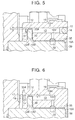
FIG. 5 is an enlarged sectional view of the cam cap of the first embodiment; -
FIG. 6 is an enlarged sectional view of a cam cap of a second embodiment; -
FIG. 7 is a sectional view of a bearing for a camshaft in related art; and -
FIG. 8 is a sectional view taken along the line VIII-VIII inFIG. 7 . - Hereinafter, a cam cap according to a first embodiment will be described with reference to
FIG. 1 to FIG. 5 . First, the relationship between camshafts and a crankshaft in an internal combustion engine provided with the cam cap of the first embodiment will be described with reference toFIG. 1 . - As illustrated in
FIG. 1 , in the internal combustion engine provided with the cam cap of the first embodiment, acylinder block 2 is fixed to the bottom of acylinder head 1. Anoil pan 5, in which oil is stored, is fixed to the bottom of thecylinder block 2. - A
crankshaft 23 to which asprocket 22 is attached, is rotatably supported by a lower portion of thecylinder block 2. Acylinder head cover 6 that covers the upper side of thecylinder head 1 is fixed to the top of thecylinder head 1. Thecylinder head 1 includes a cylinder head body 7 that is fixed to the top of thecylinder block 2, and acam housing 8 that is fixed to the top of the cylinder head body 7. - Two
camshafts 30 are rotatably supported by thecam housing 8. The twocamshafts 30 are an intake camshaft and an exhaust camshaft. Asprocket 20 is attached to each of the twocamshafts 30. Atiming chain 21 is looped over thesprocket 22 attached to thecrankshaft 23 and the twosprockets 20. - With this configuration, when the
crankshaft 23 rotates, the twocamshafts 30 also rotate in conjunction with the rotation of thecrankshaft 23. Thecrankshaft 23 rotates in an R2 direction during an operation of the engine. Anoil pump 24 is connected to thecrankshaft 23. Theoil pump 24 is driven by the rotation of thecrankshaft 23. Theoil pump 24 draws the lubricating oil up from theoil pan 5, and supplies the lubricating oil to various portions of the engine through lubricating oil passages provided inside thecylinder block 2 and thecylinder head 1. The lubricating oil supplied to the various portions of the engine flows downward through the inside of thecylinder head 1 and the inside of thecylinder block 2, and is then stored in theoil pan 5 again. - As illustrated in
FIG. 2 , acam cap 10 of the first embodiment is attached to thecam housing 8, so that thecam cap 10 and thecam housing 8 constitute bearings.FIG. 2 is a perspective view of thecam cap 10 and thecam housing 8 when thecam housing 8 is viewed from a position on the cylinder head body 7 side. - As illustrated in
FIG. 2 , thecam housing 8 includes a plurality ofsupport walls 8X in the form of a ladder. Eachsupport wall 8X has two cam housingconcave portions 8A in a semicircular shape. One cam cap is attached to eachsupport wall 8X. In this way, the bearings that support the twocamshafts 30 are provided. - The
cam cap 10 of the first embodiment is attached to thesupport wall 8X that is closest to thesprocket 20 among all thesupport walls 8X. Thecam cap 10 has cam capconcave portions 10A in a semicircular shape. The cam capconcave portions 10A are located at such positions so as to face the cam housingconcave portions 8A. - Thus, when the
cam cap 10 is attached to thecam housing 8 as illustrated inFIG. 2 , the cam housingconcave portions 8A and the cam capconcave portions 10A constitute the circular bearings. - A lower surface of the
cam housing 8 includes anoil hole 8C. When thecam housing 8 is attached to the cylinder head body 7, theoil hole 8C is connected to a lubricating oil passage provided in the cylinder head body 7. Thus, a part of the lubricating oil supplied from theoil pan 5 to the cylinder head body 7 via thecylinder block 2, is introduced into thecam housing 8 through theoil hole 8C. - As illustrated in
FIG. 3 , a camcap oil groove 11A is provided in alower end 10C of thecam cap 10. The lubricating oil supplied through theoil hole 8C of thecam housing 8 is introduced through the camcap oil groove 11A to the cam capconcave portion 10A. Acommunication groove 11B that connects the two cam capconcave portions 10A to each other is provided in thelower end 10C of thecam cap 10. Thecommunication groove 11B is located at a position between the two cam capconcave portions 10A. - As illustrated in
FIG. 4 , thejournal 35 of thecamshaft 30 includes acamshaft oil groove 32. Thejournal 35 is supported by thecam cap 10. Thecamshaft oil groove 32 has an annular shape and extends along the entire circumference of thejournal 35. - Thus, the lubricating oil introduced to the
cam housing 8 through theoil hole 8C is then introduced into one of the cam capconcave portions 10A through the camcap oil groove 11A, and is supplied through thecamshaft oil groove 32 to a sliding section at which thejournal 35 and one of the bearings slide with respect to each other. The lubricating oil is also introduced into the other one of the cam capconcave portions 10A through thecommunication groove 11B. Thus, in the other one of the bearings to which the lubricating oil is supplied through thecommunication groove 11B, the lubricating oil is also supplied to a sliding section at which thejournal 35 and the other one of the bearings slide over each other. - As illustrated in
FIG. 4 , thejournal 35 of thecamshaft 30 has athrust plate 33 that is a disk-shaped protrusion. As illustrated inFIG. 3 andFIG. 4 , each cam capconcave portion 10A of thecam cap 10 includes anaccommodating groove 12. Thus, as illustrated inFIG. 4 , thethrust plate 33 is accommodated in theaccommodating groove 12. In the internal combustion engine, thethrust plate 33 is accommodated in theaccommodating groove 12 of thecam cap 10, and thus the axial movement of thecamshaft 30 is restricted. - The
sprocket 20 is attached to an end portion of thecamshaft 30 with abolt 40. As described with reference toFIG. 1 , thetiming chain 21 is looped over thesprocket 20, and tension of thetiming chain 21 is applied to thesprocket 20. Thus, a moment in an R3 direction is generated in thecamshaft 30. As a result, in the internal combustion engine, thethrust plate 33 is pressed against afirst sidewall 12A positioned on thesprocket 20 side, and a load is applied to thefirst sidewall 12A. Thefirst sidewall 12A is one of a pair of first andsecond sidewalls accommodating groove 12, and thethrust plate 33 is interposed between thefirst sidewall 12A and thesecond sidewall 12B. - The lubricating oil needs to be sufficiently supplied to a portion to which the
thrust plate 33 is pressed due to the tension of thetiming chain 21. However, even when the lubricating oil reaches theaccommodating groove 12 through a gap between thejournal 35 and the cam capconcave portion 10A, it may be difficult to cause the lubricating oil to flow along the outside of thethrust plate 33 and guide the lubricating oil to thefirst sidewall 12A positioned on thesprocket 20 side. - An accommodating groove, in which the
thrust plate 33 is accommodated, is not provided in thecam housing 8 that covers thejournal 35 from below, and theaccommodating groove 12 is open at thelower end 10C of thecam cap 10 as illustrated inFIG. 2 . Thus, the lubricating oil leaks from openings of theaccommodating groove 12 which are located at thelower end 10C. This may make it difficult to supply the lubricating oil from the gap between thejournal 35 and the cam capconcave portion 10A to thefirst sidewall 12A. - In view of this, the
cam cap 10 is provided with anoil passage 13 and anoil reservoir 14 through which the lubricating oil is introduced to thefirst sidewall 12A. With reference toFIG. 5 , theoil passage 13 and theoil reservoir 14 will be described in detail. - As illustrated in
FIG. 5 , thecam cap 10 includes avertical hole 13V that is open at a position facing thecamshaft oil groove 32 and extends in the radial direction of thecamshaft 30. Thevertical hole 13V is a perforation formed by machining from the cam capconcave portion 10A side. As illustrated inFIG. 3 , each bearing includes onevertical hole 13V. - The
cam cap 10 includes ahorizontal hole 13H that intersects with both thevertical hole 13V and theaccommodating groove 12. Thehorizontal hole 13H is a perforation that is formed, by machining, so as to extend from the right side surface of thecam cap 10 inFIG. 5 toward the left side surface thereof inFIG. 5 . Anopening 15 of thehorizontal hole 13H on the side surface of thecam cap 10 is closed by a sealingplug 16. Thevertical hole 13V and thehorizontal hole 13H constitute theoil passage 13 that is open at the position facing thecamshaft oil groove 32 and is in communication with theaccommodating groove 12. - As illustrated in
FIG. 4 , thehorizontal hole 13H extends toward thesprocket 20 beyond the accommodating groove 12 (i.e., thehorizontal hole 13H extends to a position that is closer to thesprocket 20 than theaccommodating groove 12 is). Thus, a recess is formed in thefirst sidewall 12A, and the recess is formed of a distal end portion of thehorizontal hole 13H. Thefirst sidewall 12A is one of the pair of first andsecond sidewalls accommodating groove 12, and thefirst sidewall 12A is opposed to thesecond sidewall 12B on which theoil passage 13 is open. In thecam cap 10, the recess serves as theoil reservoir 14. Theoil passage 13 is located at a position further from thesprocket 20 than theaccommodating groove 12 is (i.e., the distance from thesprocket 20 to theoil passage 13 is greater than the distance from thesprocket 20 to the accommodating groove 12). That is, thecam cap 10 is placed on thejournal 35 such that theaccommodating groove 12 is located at a position closer to thesprocket 20 than theoil passage 13 is. - As illustrated in
FIG. 5 , the position of thehorizontal hole 13H is set such that theoil passage 13 and theoil reservoir 14 communicate with each other at a position outward of an outerperipheral edge 33A of thethrust plate 33 in the radial direction of thethrust plate 33, when thethrust plate 33 is accommodated in theaccommodating groove 12. The position of thehorizontal hole 13H is set such that the outerperipheral edge 33A of thethrust plate 33 is positioned in thehorizontal hole 13H and a gap G is formed between the outerperipheral edge 33A of thethrust plate 33 and the wall surface of thehorizontal hole 13H. - Next, an operation of the
cam cap 10 will be described. The lubricating oil supplied through theoil hole 8C of thecam housing 8 is supplied to the sliding sections, at which the bearings and thejournals 35 slide with respect to each other, through the camcap oil groove 11A, thecommunication groove 11B, and thecamshaft oil grooves 32. Because the opening of thevertical hole 13V, which is the opening of theoil passage 13, is located at a position facing thecamshaft oil groove 32, a part of the lubricating oil supplied through thecamshaft oil groove 32 flows into theoil passage 13. The lubricating oil, which has flowed into theoil passage 13, reaches theoil reservoir 14 through the gap G located radially outward of the outerperipheral edge 33A of thethrust plate 33. Then, the lubricating oil accumulated in theoil reservoir 14 is supplied to a sliding section at which thefirst sidewall 12A of theaccommodating groove 12 and thethrust plate 33 slide with respect to each other. - The
cam cap 10 of the first embodiment produces the following advantageous effects. The lubricating oil supplied from thecamshaft oil groove 32 is introduced from the outside of thethrust plate 33 to theoil reservoir 14 through theoil passage 13 provided inside thecam cap 10. The lubricating oil accumulated in theoil reservoir 14, which is located closer to thesprocket 20 than thethrust plate 33 is, is supplied to the sliding section at which thefirst sidewall 12A of theaccommodating groove 12, which is located on thesprocket 20 side, and thethrust plate 33 slide with respect to each other. Thus, it is possible to also supply the lubricating oil to thefirst sidewall 12A of theaccommodating groove 12 in which thethrust plate 33 is accommodated. - The
vertical hole 13V extending in the radial direction of thecamshaft 30 and thehorizontal hole 13H intersecting with both thevertical hole 13V and theaccommodating groove 12 constitute theoil passage 13. The distal end portion of thehorizontal hole 13H serves as theoil reservoir 14. Thus, theoil passage 13 and theoil reservoir 14 are formed from two oil holes, that is, thevertical hole 13V and thehorizontal hole 13H. - The
horizontal hole 13H is a perforation formed from the side surface of thecam cap 10, and theopening 15 of thehorizontal hole 13H, which is located on the side surface of thecam cap 10, is sealed with the sealingplug 16. Thus, thehorizontal hole 13H is formed by machining, and therefore thehorizontal hole 13H is formed more easily than in a case where ahorizontal hole 13H is formed during casting of acam cap 10. - The
vertical hole 13V is a perforation formed to extend from the position facing thecamshaft oil groove 32. Thus, thevertical hole 13V is formed by machining, and therefore thevertical hole 13V is formed more easily than in a case where avertical hole 13V is formed during casting of acam cap 10. - Because the
horizontal hole 13H is a perforation, it is possible to adjust the flow rate of the lubricating oil to be supplied to theoil reservoir 14 by adjusting the position at which thehorizontal hole 13H is formed without changing the diameter of thehorizontal hole 13H. For example, when thehorizontal hole 13H is formed at a position inward of the position of thehorizontal hole 13H in an example illustrated inFIG. 5 , in the radial direction of thethrust plate 33, the gap G is narrowed to decrease the flow rate of the lubricating oil to be supplied to theoil reservoir 14. When the diameter of thehorizontal hole 13H is decreased in order to decrease the flow rate of the lubricating oil to be supplied to theoil reservoir 14, there is a possibility that a blade of a machining tool may be broken during machining or cleaning efficiency after machining may decrease. In contrast to this, when the flow rate of the lubricating oil to be supplied to theoil reservoir 14 is adjusted by adjusting the position where thehorizontal hole 13H is formed, it is possible to prevent the blade of the machine tool from being broken, and to prevent the cleaning efficiency after the machining from decreasing. - Next, a
cam cap 10 of a second embodiment will be described with reference toFIG. 6 . Thecam cap 10 of the second embodiment is different from thecam cap 10 of the first embodiment in that a sealing plug is provided in thecam cap 10, at a position on thesprocket 20 side. - As illustrated in
FIG. 6 , ahorizontal hole 13H that constitutes anoil passage 13 of thecam cap 10 of the second embodiment is a perforation formed by machining from a side surface of thecam cap 10, which is located on thesprocket 20 side. Like thehorizontal hole 13H of thecam cap 10 of the first embodiment, thehorizontal hole 13H of the second embodiment intersects with both thevertical hole 13V and theaccommodating groove 12. Anopening 17 of thehorizontal hole 13H is sealed with a sealingplug 18. Thus, in thecam cap 10 of the second embodiment, a space is formed between the sealingplug 18 and thethrust plate 33, and the space serves as anoil reservoir 14. That is, in thecam cap 10 of the second embodiment, theoil reservoir 14 is formed of an end portion of thehorizontal hole 13H, the end portion being located on thesprocket 20 side and sealed with the sealingplug 18. - The
cam cap 10 of the second embodiment produces advantageous effects similar to those of the first embodiment. That is, a part of the lubricating oil supplied through thecamshaft oil groove 32 flows into theoil passage 13. The lubricating oil, which has flowed into theoil passage 13, reaches theoil reservoir 14 through the gap G located radially outward of the outerperipheral edge 33A of thethrust plate 33. Then, the lubricating oil accumulated in theoil reservoir 14 is supplied to a sliding section at which thefirst sidewall 12A of theaccommodating groove 12 and thethrust plate 33 slide with respect to each other. - In the
cam cap 10 of the second embodiment, theoil reservoir 14 is formed of the space between theaccommodating groove 12 and the sealingplug 18. Thus, it is possible to adjust the volume of theoil reservoir 14 by adjusting the shape of the sealingplug 18, such as the thickness thereof. - When the
cam cap 10 is manufactured, a process of fitting the sealingplug 18 into theopening 17 of thehorizontal hole 13H is performed after a process of machining for forming thehorizontal hole 13H. Thus, in thecam cap 10 of the second embodiment, it is possible to adjust the volume of theoil reservoir 14 in the process performed after the process of machining. - The
cam cap 10 of the second embodiment produces the following advantageous effects, in addition to the advantageous effects produced by thecam cap 10 of the first embodiment. Theoil reservoir 14 is formed of the end portion of thehorizontal hole 13H, the end portion being on thesprocket 20 side and sealed with the sealingplug 18. Thus, it is possible to adjust the depth of theoil reservoir 14, that is, the volume of theoil reservoir 14, by adjusting the shape of the sealingplug 18. Because it is possible to adjust the volume of theoil reservoir 14 in the process performed after the process of machining, the flexibility in manufacturing is enhanced. - Elements that may be modified in each of the foregoing embodiments are as follows. In the
cam cap 10 of each of the foregoing embodiments, theoil passage 13 and theoil reservoir 14 are provided in each of the two bearings that support the twocamshafts 30, that is, the bearing that supports the intake camshaft and the bearing that supports the exhaust camshaft. However, theoil passage 13 and theoil reservoir 14 may be provided in only one of the two bearings. - In each of the foregoing embodiments, the
cam cap 10 including theoil passage 13 and theoil reservoir 14 is employed in the internal combustion engine in which accommodating grooves for accommodating thethrust plates 33 are not provided in thecam housing 8. However, acam cap 10 similar to the one in each of the foregoing embodiments may be employed in an internal combustion engine in which accommodating grooves for accommodating thethrust plates 33 are provided in acam housing 8. - In each of the foregoing embodiments, the
cam cap 10, including theoil passage 13 and theoil reservoir 14, is employed as a cam cap that constitutes each bearing that supports thejournal 35 closest to thesprocket 20. However, acam cap 10 similar to the one in each of the foregoing embodiments may be used for anotherjournal 35. - In each of the foregoing embodiments, the
oil passage 13 is a perforation. However, the method for forming theoil passage 13 may be changed. For example, anoil passage 13 may be formed during casting of thecam cap 10. For example, any one of thevertical hole 13V and thehorizontal hole 13H may be formed during casting of thecam cap 10, or both thevertical hole 13V and thehorizontal hole 13H may be formed during casting of thecam cap 10. - In each of the foregoing embodiments, the
vertical hole 13V and thehorizontal hole 13H that intersect with each other constitute theoil passage 13. However, the shape of theoil passage 13 may be changed. For example, anoil passage 13 may be formed such that theoil passage 13 extends straight from a position facing thecamshaft oil groove 32 so as to intersect with theaccommodating groove 12. Further, an intermediate portion of theoil passage 13 may be curved. - In each of the foregoing embodiments, each of the bearings formed by the
cam cap 10 includes oneoil passage 13 and onereservoir 14. However, each of the bearings may include a plurality ofoil passages 13 and a plurality ofoil reservoirs 14. - The
cam cap 10 of each of the foregoing embodiments has two cam capconcave portions 10A and supports the twocamshafts 30. However, theoil passage 13 and theoil reservoir 14 may be provided in a cam cap that has one cam cap concave portion and supports one camshaft, or a cam cap that has three or more cam cap concave portions and supports three or more camshafts.
Claims (5)
- A cam cap (10) configured to be placed on a journal (35) of a camshaft (30) provided with a sprocket (20), the cam cap (10) constituting a bearing that is configured to support the journal (35), the cam cap (10) characterized by comprising:an accommodating groove (12) in which a thrust plate (33) provided on the journal (35) is configured to be accommodated;an oil passage (13) opened at a position configured to face a camshaft oil groove (32) provided in the journal (35), the oil passage (13) configured to communicate with the accommodating groove (12); andan oil reservoir (14) provided in a first sidewall (12A) of a pair of first and second sidewalls (12A, 12B) of the accommodating groove (12), the first sidewall (12A) being opposed to the second sidewall (12B) on which the oil passage (13) is open, the oil reservoir (14) being a recess, whereinthe cam cap (10) is configured to be placed on the journal (35) such that the accommodating groove (12) is located at a position closer to the sprocket (20) than the oil passage (13) is, andwhen the thrust plate (33) is accommodated in the accommodating groove (12), the oil passage (13) and the oil reservoir (14) communicate with each other, at a position outward of an outer peripheral edge (33A) of the thrust plate (33) in a radial direction of the thrust plate (33).
- The cam cap according to claim 1, wherein:the oil passage (13) has a vertical hole (13V) and a horizontal hole (13H);the vertical hole (13V) is configured to extend in a radial direction of the camshaft (30) from a position facing the camshaft oil groove (32);the horizontal hole (13H) intersects with the vertical hole (13V) and the accommodating groove (12); andthe oil reservoir (14) is a distal end portion of the horizontal hole (13H).
- The cam cap according to claim 2, further comprising a sealing plug (16) that seals an opening (15) of the horizontal hole (13H), the opening (15) being located on a side surface of the cam cap (10), wherein
the horizontal hole (13H) is a perforation extending from the side surface of the cam cap (10). - The cam cap according to claim 1, further comprising a sealing plug (18), wherein:the oil passage (13) has a vertical hole (13V) and a horizontal hole (13H);the vertical hole (13V) is configured to extend in a radial direction of the camshaft (30) from a position facing the camshaft oil groove (32);the horizontal hole (13H) extends from a side surface of the cam cap (10), the side surface being located on the sprocket (20) side, and the horizontal hole (13H) being a perforation intersecting with the accommodating groove (12) and the vertical hole (13V);the sealing plug (18) seals an opening (17) of the horizontal hole (13H), the opening (17) being located on the side surface; andthe oil reservoir (14) is an end portion of the horizontal hole (13H), the end portion being located on the sprocket (20) side.
- The cam cap according to any one of claims 2 to 4, wherein the vertical hole (13V) is a perforation provided at a position configured to face the camshaft oil groove (32).
Applications Claiming Priority (1)
| Application Number | Priority Date | Filing Date | Title |
|---|---|---|---|
| JP2015070070A JP6131981B2 (en) | 2015-03-30 | 2015-03-30 | Cam cap |
Publications (2)
| Publication Number | Publication Date |
|---|---|
| EP3078818A1 true EP3078818A1 (en) | 2016-10-12 |
| EP3078818B1 EP3078818B1 (en) | 2019-01-30 |
Family
ID=55696966
Family Applications (1)
| Application Number | Title | Priority Date | Filing Date |
|---|---|---|---|
| EP16162828.4A Not-in-force EP3078818B1 (en) | 2015-03-30 | 2016-03-30 | Cam cap |
Country Status (4)
| Country | Link |
|---|---|
| US (1) | US9920662B2 (en) |
| EP (1) | EP3078818B1 (en) |
| JP (1) | JP6131981B2 (en) |
| CN (1) | CN106014526B (en) |
Families Citing this family (4)
| Publication number | Priority date | Publication date | Assignee | Title |
|---|---|---|---|---|
| DE102015224440A1 (en) * | 2015-12-07 | 2017-06-08 | Mahle International Gmbh | Cylinder head cover |
| US10151223B2 (en) * | 2016-06-09 | 2018-12-11 | Ford Global Technologies, Llc | Valve deactivating system for an engine |
| CN113323767A (en) * | 2021-07-15 | 2021-08-31 | 安徽江淮汽车集团股份有限公司 | Engine camshaft shroud and camshaft |
| DE102022133736A1 (en) * | 2022-12-16 | 2024-06-27 | Rolls-Royce Solutions GmbH | Bearing arrangement for a camshaft of an internal combustion engine and crankcase with the same |
Citations (7)
| Publication number | Priority date | Publication date | Assignee | Title |
|---|---|---|---|---|
| DE1295275B (en) * | 1965-05-25 | 1969-05-14 | Buckau Wolf Maschf R | Valve-controlled multi-cylinder internal combustion engine |
| DE3923984A1 (en) * | 1988-07-20 | 1990-01-25 | Mazda Motor | VALVE DRIVE FOR A V-DESIGN INTERNAL COMBUSTION ENGINE WITH DOUBLE OVERHEAD CAMSHAFT |
| US4957079A (en) * | 1988-12-03 | 1990-09-18 | Mazda Motor Corporation | Camshaft structure for double overhead camshaft engine |
| JPH03123908U (en) * | 1990-03-28 | 1991-12-17 | ||
| JPH08200029A (en) * | 1995-01-26 | 1996-08-06 | Kawasaki Heavy Ind Ltd | Lubrication structure of thrust receiving part of camshaft |
| JPH09242523A (en) | 1996-03-04 | 1997-09-16 | Toyota Motor Corp | Camshaft lubrication structure for valve train of internal combustion engine |
| JPH11315708A (en) * | 1998-04-30 | 1999-11-16 | Suzuki Motor Corp | Cylinder head lubricating oil passage structure |
Family Cites Families (14)
| Publication number | Priority date | Publication date | Assignee | Title |
|---|---|---|---|---|
| JPS5916490Y2 (en) * | 1978-05-13 | 1984-05-15 | ダイハツ工業株式会社 | Camshaft bearing device in internal combustion engine |
| JPS59192605U (en) * | 1983-06-08 | 1984-12-21 | マツダ株式会社 | Camshaft thrust bearing structure |
| JPH0646005B2 (en) * | 1984-06-12 | 1994-06-15 | ヤマハ発動機株式会社 | Bearing structure of valve camshaft |
| JPS6134307A (en) * | 1984-07-27 | 1986-02-18 | Nissan Motor Co Ltd | Thrust receiving structure for cam shaft |
| JPS628424U (en) * | 1985-07-01 | 1987-01-19 | ||
| JPS628425U (en) * | 1985-07-01 | 1987-01-19 | ||
| JP3284888B2 (en) * | 1996-07-03 | 2002-05-20 | トヨタ自動車株式会社 | Oil passage structure of internal combustion engine |
| JP4070857B2 (en) * | 1997-12-17 | 2008-04-02 | トヨタ自動車株式会社 | Valve characteristic control device for internal combustion engine |
| JP3817716B2 (en) * | 2002-01-30 | 2006-09-06 | 愛知機械工業株式会社 | Cam bracket |
| JP4248502B2 (en) * | 2005-01-07 | 2009-04-02 | トヨタ自動車株式会社 | Mounting structure of functional device for internal combustion engine |
| KR100786905B1 (en) * | 2006-11-01 | 2007-12-17 | 현대자동차주식회사 | Lubrication structure of camshaft with variable valve timing |
| JP5378091B2 (en) * | 2008-11-27 | 2013-12-25 | 本田技研工業株式会社 | Structure for fixing the rotary shaft of a valve operating system of an internal combustion engine |
| JP5846374B2 (en) | 2012-01-16 | 2016-01-20 | スズキ株式会社 | Camshaft thrust bearing lubrication structure |
| DE102013205129A1 (en) * | 2013-03-22 | 2014-09-25 | Mahle International Gmbh | Bearing frame or cylinder head cover of an internal combustion engine |
-
2015
- 2015-03-30 JP JP2015070070A patent/JP6131981B2/en not_active Expired - Fee Related
-
2016
- 2016-03-29 US US15/083,933 patent/US9920662B2/en active Active
- 2016-03-30 CN CN201610191703.6A patent/CN106014526B/en not_active Expired - Fee Related
- 2016-03-30 EP EP16162828.4A patent/EP3078818B1/en not_active Not-in-force
Patent Citations (7)
| Publication number | Priority date | Publication date | Assignee | Title |
|---|---|---|---|---|
| DE1295275B (en) * | 1965-05-25 | 1969-05-14 | Buckau Wolf Maschf R | Valve-controlled multi-cylinder internal combustion engine |
| DE3923984A1 (en) * | 1988-07-20 | 1990-01-25 | Mazda Motor | VALVE DRIVE FOR A V-DESIGN INTERNAL COMBUSTION ENGINE WITH DOUBLE OVERHEAD CAMSHAFT |
| US4957079A (en) * | 1988-12-03 | 1990-09-18 | Mazda Motor Corporation | Camshaft structure for double overhead camshaft engine |
| JPH03123908U (en) * | 1990-03-28 | 1991-12-17 | ||
| JPH08200029A (en) * | 1995-01-26 | 1996-08-06 | Kawasaki Heavy Ind Ltd | Lubrication structure of thrust receiving part of camshaft |
| JPH09242523A (en) | 1996-03-04 | 1997-09-16 | Toyota Motor Corp | Camshaft lubrication structure for valve train of internal combustion engine |
| JPH11315708A (en) * | 1998-04-30 | 1999-11-16 | Suzuki Motor Corp | Cylinder head lubricating oil passage structure |
Also Published As
| Publication number | Publication date |
|---|---|
| EP3078818B1 (en) | 2019-01-30 |
| US20160290182A1 (en) | 2016-10-06 |
| CN106014526B (en) | 2018-10-09 |
| CN106014526A (en) | 2016-10-12 |
| JP6131981B2 (en) | 2017-05-24 |
| US9920662B2 (en) | 2018-03-20 |
| JP2016191307A (en) | 2016-11-10 |
Similar Documents
| Publication | Publication Date | Title |
|---|---|---|
| EP2089612B1 (en) | Cam cap and oil passage connection structure | |
| EP3078818B1 (en) | Cam cap | |
| CN101815850B (en) | Engine | |
| JP3817716B2 (en) | Cam bracket | |
| CN107842403A (en) | Camshaft phasing system for an internal combustion engine including an idler gear phaser | |
| EP1703093B1 (en) | Oil supply apparatus | |
| EP2902598A1 (en) | Mechanism for supplying engine lubricating oil | |
| JP2011080384A (en) | Vehicle engine | |
| JP2010164009A (en) | Lubricating oil supply structure | |
| JP5063405B2 (en) | Cylinder head device, internal combustion engine equipped with the same, and method of manufacturing cylinder head device | |
| JP2008106617A (en) | Valve timing changing device and cam cap for internal combustion engine | |
| JP2019011742A (en) | Lubricant supply mechanism of engine | |
| JP2002250211A (en) | Skirt lubricating structure | |
| US9994294B1 (en) | Outboard marine engines having vertical camshaft arrangements | |
| JP2015028329A (en) | Lubricating oil supply mechanism for engine | |
| JP2016205323A (en) | Lubricant supply structure of internal combustion engine | |
| JPWO2011086815A1 (en) | Engine with variable valve system | |
| JP2013160363A (en) | Seal structure of oil path of engine | |
| JP5585789B2 (en) | Camshaft lubrication structure | |
| JP2004169591A (en) | Lubricating oil passage structure in cylinder block of internal combustion engine | |
| KR100208047B1 (en) | Oil passage structure of cylinder head for air-cooled internal combustion engine | |
| JP2003120221A (en) | Tappet of internal combustion engine | |
| JP2014034907A (en) | Lubricating structure of timing chain | |
| JP5748056B2 (en) | Camshaft lubrication structure | |
| JP2016188615A (en) | Engine valve device |
Legal Events
| Date | Code | Title | Description |
|---|---|---|---|
| PUAI | Public reference made under article 153(3) epc to a published international application that has entered the european phase |
Free format text: ORIGINAL CODE: 0009012 |
|
| 17P | Request for examination filed |
Effective date: 20160331 |
|
| AK | Designated contracting states |
Kind code of ref document: A1 Designated state(s): AL AT BE BG CH CY CZ DE DK EE ES FI FR GB GR HR HU IE IS IT LI LT LU LV MC MK MT NL NO PL PT RO RS SE SI SK SM TR |
|
| AX | Request for extension of the european patent |
Extension state: BA ME |
|
| GRAP | Despatch of communication of intention to grant a patent |
Free format text: ORIGINAL CODE: EPIDOSNIGR1 |
|
| STAA | Information on the status of an ep patent application or granted ep patent |
Free format text: STATUS: GRANT OF PATENT IS INTENDED |
|
| INTG | Intention to grant announced |
Effective date: 20180815 |
|
| GRAS | Grant fee paid |
Free format text: ORIGINAL CODE: EPIDOSNIGR3 |
|
| GRAA | (expected) grant |
Free format text: ORIGINAL CODE: 0009210 |
|
| STAA | Information on the status of an ep patent application or granted ep patent |
Free format text: STATUS: THE PATENT HAS BEEN GRANTED |
|
| AK | Designated contracting states |
Kind code of ref document: B1 Designated state(s): AL AT BE BG CH CY CZ DE DK EE ES FI FR GB GR HR HU IE IS IT LI LT LU LV MC MK MT NL NO PL PT RO RS SE SI SK SM TR |
|
| REG | Reference to a national code |
Ref country code: GB Ref legal event code: FG4D |
|
| REG | Reference to a national code |
Ref country code: CH Ref legal event code: EP |
|
| REG | Reference to a national code |
Ref country code: AT Ref legal event code: REF Ref document number: 1093444 Country of ref document: AT Kind code of ref document: T Effective date: 20190215 |
|
| REG | Reference to a national code |
Ref country code: IE Ref legal event code: FG4D |
|
| REG | Reference to a national code |
Ref country code: DE Ref legal event code: R096 Ref document number: 602016009546 Country of ref document: DE |
|
| REG | Reference to a national code |
Ref country code: DE Ref legal event code: R084 Ref document number: 602016009546 Country of ref document: DE |
|
| REG | Reference to a national code |
Ref country code: GB Ref legal event code: 746 Effective date: 20190430 |
|
| REG | Reference to a national code |
Ref country code: LT Ref legal event code: MG4D |
|
| REG | Reference to a national code |
Ref country code: NL Ref legal event code: MP Effective date: 20190130 |
|
| PG25 | Lapsed in a contracting state [announced via postgrant information from national office to epo] |
Ref country code: ES Free format text: LAPSE BECAUSE OF FAILURE TO SUBMIT A TRANSLATION OF THE DESCRIPTION OR TO PAY THE FEE WITHIN THE PRESCRIBED TIME-LIMIT Effective date: 20190130 Ref country code: FI Free format text: LAPSE BECAUSE OF FAILURE TO SUBMIT A TRANSLATION OF THE DESCRIPTION OR TO PAY THE FEE WITHIN THE PRESCRIBED TIME-LIMIT Effective date: 20190130 Ref country code: NO Free format text: LAPSE BECAUSE OF FAILURE TO SUBMIT A TRANSLATION OF THE DESCRIPTION OR TO PAY THE FEE WITHIN THE PRESCRIBED TIME-LIMIT Effective date: 20190430 Ref country code: PT Free format text: LAPSE BECAUSE OF FAILURE TO SUBMIT A TRANSLATION OF THE DESCRIPTION OR TO PAY THE FEE WITHIN THE PRESCRIBED TIME-LIMIT Effective date: 20190530 Ref country code: SE Free format text: LAPSE BECAUSE OF FAILURE TO SUBMIT A TRANSLATION OF THE DESCRIPTION OR TO PAY THE FEE WITHIN THE PRESCRIBED TIME-LIMIT Effective date: 20190130 Ref country code: PL Free format text: LAPSE BECAUSE OF FAILURE TO SUBMIT A TRANSLATION OF THE DESCRIPTION OR TO PAY THE FEE WITHIN THE PRESCRIBED TIME-LIMIT Effective date: 20190130 Ref country code: NL Free format text: LAPSE BECAUSE OF FAILURE TO SUBMIT A TRANSLATION OF THE DESCRIPTION OR TO PAY THE FEE WITHIN THE PRESCRIBED TIME-LIMIT Effective date: 20190130 Ref country code: LT Free format text: LAPSE BECAUSE OF FAILURE TO SUBMIT A TRANSLATION OF THE DESCRIPTION OR TO PAY THE FEE WITHIN THE PRESCRIBED TIME-LIMIT Effective date: 20190130 |
|
| REG | Reference to a national code |
Ref country code: AT Ref legal event code: MK05 Ref document number: 1093444 Country of ref document: AT Kind code of ref document: T Effective date: 20190130 |
|
| PG25 | Lapsed in a contracting state [announced via postgrant information from national office to epo] |
Ref country code: HR Free format text: LAPSE BECAUSE OF FAILURE TO SUBMIT A TRANSLATION OF THE DESCRIPTION OR TO PAY THE FEE WITHIN THE PRESCRIBED TIME-LIMIT Effective date: 20190130 Ref country code: BG Free format text: LAPSE BECAUSE OF FAILURE TO SUBMIT A TRANSLATION OF THE DESCRIPTION OR TO PAY THE FEE WITHIN THE PRESCRIBED TIME-LIMIT Effective date: 20190430 Ref country code: RS Free format text: LAPSE BECAUSE OF FAILURE TO SUBMIT A TRANSLATION OF THE DESCRIPTION OR TO PAY THE FEE WITHIN THE PRESCRIBED TIME-LIMIT Effective date: 20190130 Ref country code: GR Free format text: LAPSE BECAUSE OF FAILURE TO SUBMIT A TRANSLATION OF THE DESCRIPTION OR TO PAY THE FEE WITHIN THE PRESCRIBED TIME-LIMIT Effective date: 20190501 Ref country code: LV Free format text: LAPSE BECAUSE OF FAILURE TO SUBMIT A TRANSLATION OF THE DESCRIPTION OR TO PAY THE FEE WITHIN THE PRESCRIBED TIME-LIMIT Effective date: 20190130 Ref country code: IS Free format text: LAPSE BECAUSE OF FAILURE TO SUBMIT A TRANSLATION OF THE DESCRIPTION OR TO PAY THE FEE WITHIN THE PRESCRIBED TIME-LIMIT Effective date: 20190530 |
|
| PG25 | Lapsed in a contracting state [announced via postgrant information from national office to epo] |
Ref country code: EE Free format text: LAPSE BECAUSE OF FAILURE TO SUBMIT A TRANSLATION OF THE DESCRIPTION OR TO PAY THE FEE WITHIN THE PRESCRIBED TIME-LIMIT Effective date: 20190130 Ref country code: SK Free format text: LAPSE BECAUSE OF FAILURE TO SUBMIT A TRANSLATION OF THE DESCRIPTION OR TO PAY THE FEE WITHIN THE PRESCRIBED TIME-LIMIT Effective date: 20190130 Ref country code: DK Free format text: LAPSE BECAUSE OF FAILURE TO SUBMIT A TRANSLATION OF THE DESCRIPTION OR TO PAY THE FEE WITHIN THE PRESCRIBED TIME-LIMIT Effective date: 20190130 Ref country code: IT Free format text: LAPSE BECAUSE OF FAILURE TO SUBMIT A TRANSLATION OF THE DESCRIPTION OR TO PAY THE FEE WITHIN THE PRESCRIBED TIME-LIMIT Effective date: 20190130 Ref country code: MC Free format text: LAPSE BECAUSE OF FAILURE TO SUBMIT A TRANSLATION OF THE DESCRIPTION OR TO PAY THE FEE WITHIN THE PRESCRIBED TIME-LIMIT Effective date: 20190130 Ref country code: AL Free format text: LAPSE BECAUSE OF FAILURE TO SUBMIT A TRANSLATION OF THE DESCRIPTION OR TO PAY THE FEE WITHIN THE PRESCRIBED TIME-LIMIT Effective date: 20190130 Ref country code: CZ Free format text: LAPSE BECAUSE OF FAILURE TO SUBMIT A TRANSLATION OF THE DESCRIPTION OR TO PAY THE FEE WITHIN THE PRESCRIBED TIME-LIMIT Effective date: 20190130 Ref country code: RO Free format text: LAPSE BECAUSE OF FAILURE TO SUBMIT A TRANSLATION OF THE DESCRIPTION OR TO PAY THE FEE WITHIN THE PRESCRIBED TIME-LIMIT Effective date: 20190130 |
|
| REG | Reference to a national code |
Ref country code: CH Ref legal event code: PL Ref country code: DE Ref legal event code: R097 Ref document number: 602016009546 Country of ref document: DE |
|
| PG25 | Lapsed in a contracting state [announced via postgrant information from national office to epo] |
Ref country code: LU Free format text: LAPSE BECAUSE OF NON-PAYMENT OF DUE FEES Effective date: 20190330 Ref country code: SM Free format text: LAPSE BECAUSE OF FAILURE TO SUBMIT A TRANSLATION OF THE DESCRIPTION OR TO PAY THE FEE WITHIN THE PRESCRIBED TIME-LIMIT Effective date: 20190130 |
|
| PLBE | No opposition filed within time limit |
Free format text: ORIGINAL CODE: 0009261 |
|
| STAA | Information on the status of an ep patent application or granted ep patent |
Free format text: STATUS: NO OPPOSITION FILED WITHIN TIME LIMIT |
|
| REG | Reference to a national code |
Ref country code: BE Ref legal event code: MM Effective date: 20190331 |
|
| PG25 | Lapsed in a contracting state [announced via postgrant information from national office to epo] |
Ref country code: AT Free format text: LAPSE BECAUSE OF FAILURE TO SUBMIT A TRANSLATION OF THE DESCRIPTION OR TO PAY THE FEE WITHIN THE PRESCRIBED TIME-LIMIT Effective date: 20190130 |
|
| 26N | No opposition filed |
Effective date: 20191031 |
|
| PG25 | Lapsed in a contracting state [announced via postgrant information from national office to epo] |
Ref country code: LI Free format text: LAPSE BECAUSE OF NON-PAYMENT OF DUE FEES Effective date: 20190331 Ref country code: IE Free format text: LAPSE BECAUSE OF NON-PAYMENT OF DUE FEES Effective date: 20190330 Ref country code: CH Free format text: LAPSE BECAUSE OF NON-PAYMENT OF DUE FEES Effective date: 20190331 |
|
| PG25 | Lapsed in a contracting state [announced via postgrant information from national office to epo] |
Ref country code: BE Free format text: LAPSE BECAUSE OF NON-PAYMENT OF DUE FEES Effective date: 20190331 Ref country code: SI Free format text: LAPSE BECAUSE OF FAILURE TO SUBMIT A TRANSLATION OF THE DESCRIPTION OR TO PAY THE FEE WITHIN THE PRESCRIBED TIME-LIMIT Effective date: 20190130 |
|
| PG25 | Lapsed in a contracting state [announced via postgrant information from national office to epo] |
Ref country code: TR Free format text: LAPSE BECAUSE OF FAILURE TO SUBMIT A TRANSLATION OF THE DESCRIPTION OR TO PAY THE FEE WITHIN THE PRESCRIBED TIME-LIMIT Effective date: 20190130 |
|
| PG25 | Lapsed in a contracting state [announced via postgrant information from national office to epo] |
Ref country code: MT Free format text: LAPSE BECAUSE OF NON-PAYMENT OF DUE FEES Effective date: 20190330 |
|
| PG25 | Lapsed in a contracting state [announced via postgrant information from national office to epo] |
Ref country code: CY Free format text: LAPSE BECAUSE OF FAILURE TO SUBMIT A TRANSLATION OF THE DESCRIPTION OR TO PAY THE FEE WITHIN THE PRESCRIBED TIME-LIMIT Effective date: 20190130 |
|
| PG25 | Lapsed in a contracting state [announced via postgrant information from national office to epo] |
Ref country code: HU Free format text: LAPSE BECAUSE OF FAILURE TO SUBMIT A TRANSLATION OF THE DESCRIPTION OR TO PAY THE FEE WITHIN THE PRESCRIBED TIME-LIMIT; INVALID AB INITIO Effective date: 20160330 |
|
| PGFP | Annual fee paid to national office [announced via postgrant information from national office to epo] |
Ref country code: GB Payment date: 20220203 Year of fee payment: 7 |
|
| PGFP | Annual fee paid to national office [announced via postgrant information from national office to epo] |
Ref country code: FR Payment date: 20220209 Year of fee payment: 7 |
|
| PG25 | Lapsed in a contracting state [announced via postgrant information from national office to epo] |
Ref country code: MK Free format text: LAPSE BECAUSE OF FAILURE TO SUBMIT A TRANSLATION OF THE DESCRIPTION OR TO PAY THE FEE WITHIN THE PRESCRIBED TIME-LIMIT Effective date: 20190130 |
|
| PGFP | Annual fee paid to national office [announced via postgrant information from national office to epo] |
Ref country code: DE Payment date: 20230131 Year of fee payment: 8 |
|
| P01 | Opt-out of the competence of the unified patent court (upc) registered |
Effective date: 20230427 |
|
| GBPC | Gb: european patent ceased through non-payment of renewal fee |
Effective date: 20230330 |
|
| PG25 | Lapsed in a contracting state [announced via postgrant information from national office to epo] |
Ref country code: GB Free format text: LAPSE BECAUSE OF NON-PAYMENT OF DUE FEES Effective date: 20230330 |
|
| PG25 | Lapsed in a contracting state [announced via postgrant information from national office to epo] |
Ref country code: GB Free format text: LAPSE BECAUSE OF NON-PAYMENT OF DUE FEES Effective date: 20230330 Ref country code: FR Free format text: LAPSE BECAUSE OF NON-PAYMENT OF DUE FEES Effective date: 20230331 |
|
| REG | Reference to a national code |
Ref country code: DE Ref legal event code: R119 Ref document number: 602016009546 Country of ref document: DE |
|
| PG25 | Lapsed in a contracting state [announced via postgrant information from national office to epo] |
Ref country code: DE Free format text: LAPSE BECAUSE OF NON-PAYMENT OF DUE FEES Effective date: 20241001 |
|
| PG25 | Lapsed in a contracting state [announced via postgrant information from national office to epo] |
Ref country code: DE Free format text: LAPSE BECAUSE OF NON-PAYMENT OF DUE FEES Effective date: 20241001 |