EP3078807B1 - Passages de refroidissement pour composant de moteur à turbine à gaz - Google Patents
Passages de refroidissement pour composant de moteur à turbine à gaz Download PDFInfo
- Publication number
- EP3078807B1 EP3078807B1 EP16164214.5A EP16164214A EP3078807B1 EP 3078807 B1 EP3078807 B1 EP 3078807B1 EP 16164214 A EP16164214 A EP 16164214A EP 3078807 B1 EP3078807 B1 EP 3078807B1
- Authority
- EP
- European Patent Office
- Prior art keywords
- diffusion
- component
- metering
- portions
- diffusion portion
- Prior art date
- Legal status (The legal status is an assumption and is not a legal conclusion. Google has not performed a legal analysis and makes no representation as to the accuracy of the status listed.)
- Active
Links
Images

Classifications
-
- F—MECHANICAL ENGINEERING; LIGHTING; HEATING; WEAPONS; BLASTING
- F01—MACHINES OR ENGINES IN GENERAL; ENGINE PLANTS IN GENERAL; STEAM ENGINES
- F01D—NON-POSITIVE DISPLACEMENT MACHINES OR ENGINES, e.g. STEAM TURBINES
- F01D5/00—Blades; Blade-carrying members; Heating, heat-insulating, cooling or antivibration means on the blades or the members
- F01D5/12—Blades
- F01D5/14—Form or construction
- F01D5/18—Hollow blades, i.e. blades with cooling or heating channels or cavities; Heating, heat-insulating or cooling means on blades
- F01D5/186—Film cooling
-
- B—PERFORMING OPERATIONS; TRANSPORTING
- B22—CASTING; POWDER METALLURGY
- B22C—FOUNDRY MOULDING
- B22C9/00—Moulds or cores; Moulding processes
- B22C9/22—Moulds for peculiarly-shaped castings
- B22C9/24—Moulds for peculiarly-shaped castings for hollow articles
-
- F—MECHANICAL ENGINEERING; LIGHTING; HEATING; WEAPONS; BLASTING
- F01—MACHINES OR ENGINES IN GENERAL; ENGINE PLANTS IN GENERAL; STEAM ENGINES
- F01D—NON-POSITIVE DISPLACEMENT MACHINES OR ENGINES, e.g. STEAM TURBINES
- F01D11/00—Preventing or minimising internal leakage of working-fluid, e.g. between stages
- F01D11/08—Preventing or minimising internal leakage of working-fluid, e.g. between stages for sealing space between rotor blade tips and stator
-
- F—MECHANICAL ENGINEERING; LIGHTING; HEATING; WEAPONS; BLASTING
- F01—MACHINES OR ENGINES IN GENERAL; ENGINE PLANTS IN GENERAL; STEAM ENGINES
- F01D—NON-POSITIVE DISPLACEMENT MACHINES OR ENGINES, e.g. STEAM TURBINES
- F01D25/00—Component parts, details, or accessories, not provided for in, or of interest apart from, other groups
- F01D25/08—Cooling; Heating; Heat-insulation
- F01D25/12—Cooling
-
- F—MECHANICAL ENGINEERING; LIGHTING; HEATING; WEAPONS; BLASTING
- F01—MACHINES OR ENGINES IN GENERAL; ENGINE PLANTS IN GENERAL; STEAM ENGINES
- F01D—NON-POSITIVE DISPLACEMENT MACHINES OR ENGINES, e.g. STEAM TURBINES
- F01D9/00—Stators
- F01D9/02—Nozzles; Nozzle boxes; Stator blades; Guide conduits, e.g. individual nozzles
- F01D9/04—Nozzles; Nozzle boxes; Stator blades; Guide conduits, e.g. individual nozzles forming ring or sector
- F01D9/041—Nozzles; Nozzle boxes; Stator blades; Guide conduits, e.g. individual nozzles forming ring or sector using blades
-
- F—MECHANICAL ENGINEERING; LIGHTING; HEATING; WEAPONS; BLASTING
- F02—COMBUSTION ENGINES; HOT-GAS OR COMBUSTION-PRODUCT ENGINE PLANTS
- F02C—GAS-TURBINE PLANTS; AIR INTAKES FOR JET-PROPULSION PLANTS; CONTROLLING FUEL SUPPLY IN AIR-BREATHING JET-PROPULSION PLANTS
- F02C3/00—Gas-turbine plants characterised by the use of combustion products as the working fluid
-
- F—MECHANICAL ENGINEERING; LIGHTING; HEATING; WEAPONS; BLASTING
- F02—COMBUSTION ENGINES; HOT-GAS OR COMBUSTION-PRODUCT ENGINE PLANTS
- F02C—GAS-TURBINE PLANTS; AIR INTAKES FOR JET-PROPULSION PLANTS; CONTROLLING FUEL SUPPLY IN AIR-BREATHING JET-PROPULSION PLANTS
- F02C7/00—Features, components parts, details or accessories, not provided for in, or of interest apart form groups F02C1/00 - F02C6/00; Air intakes for jet-propulsion plants
- F02C7/12—Cooling of plants
- F02C7/16—Cooling of plants characterised by cooling medium
- F02C7/18—Cooling of plants characterised by cooling medium the medium being gaseous, e.g. air
-
- F—MECHANICAL ENGINEERING; LIGHTING; HEATING; WEAPONS; BLASTING
- F05—INDEXING SCHEMES RELATING TO ENGINES OR PUMPS IN VARIOUS SUBCLASSES OF CLASSES F01-F04
- F05D—INDEXING SCHEME FOR ASPECTS RELATING TO NON-POSITIVE-DISPLACEMENT MACHINES OR ENGINES, GAS-TURBINES OR JET-PROPULSION PLANTS
- F05D2220/00—Application
- F05D2220/30—Application in turbines
- F05D2220/32—Application in turbines in gas turbines
-
- F—MECHANICAL ENGINEERING; LIGHTING; HEATING; WEAPONS; BLASTING
- F05—INDEXING SCHEMES RELATING TO ENGINES OR PUMPS IN VARIOUS SUBCLASSES OF CLASSES F01-F04
- F05D—INDEXING SCHEME FOR ASPECTS RELATING TO NON-POSITIVE-DISPLACEMENT MACHINES OR ENGINES, GAS-TURBINES OR JET-PROPULSION PLANTS
- F05D2230/00—Manufacture
- F05D2230/10—Manufacture by removing material
-
- F—MECHANICAL ENGINEERING; LIGHTING; HEATING; WEAPONS; BLASTING
- F05—INDEXING SCHEMES RELATING TO ENGINES OR PUMPS IN VARIOUS SUBCLASSES OF CLASSES F01-F04
- F05D—INDEXING SCHEME FOR ASPECTS RELATING TO NON-POSITIVE-DISPLACEMENT MACHINES OR ENGINES, GAS-TURBINES OR JET-PROPULSION PLANTS
- F05D2230/00—Manufacture
- F05D2230/20—Manufacture essentially without removing material
- F05D2230/21—Manufacture essentially without removing material by casting
-
- F—MECHANICAL ENGINEERING; LIGHTING; HEATING; WEAPONS; BLASTING
- F05—INDEXING SCHEMES RELATING TO ENGINES OR PUMPS IN VARIOUS SUBCLASSES OF CLASSES F01-F04
- F05D—INDEXING SCHEME FOR ASPECTS RELATING TO NON-POSITIVE-DISPLACEMENT MACHINES OR ENGINES, GAS-TURBINES OR JET-PROPULSION PLANTS
- F05D2230/00—Manufacture
- F05D2230/20—Manufacture essentially without removing material
- F05D2230/22—Manufacture essentially without removing material by sintering
-
- F—MECHANICAL ENGINEERING; LIGHTING; HEATING; WEAPONS; BLASTING
- F05—INDEXING SCHEMES RELATING TO ENGINES OR PUMPS IN VARIOUS SUBCLASSES OF CLASSES F01-F04
- F05D—INDEXING SCHEME FOR ASPECTS RELATING TO NON-POSITIVE-DISPLACEMENT MACHINES OR ENGINES, GAS-TURBINES OR JET-PROPULSION PLANTS
- F05D2240/00—Components
- F05D2240/10—Stators
- F05D2240/12—Fluid guiding means, e.g. vanes
-
- F—MECHANICAL ENGINEERING; LIGHTING; HEATING; WEAPONS; BLASTING
- F05—INDEXING SCHEMES RELATING TO ENGINES OR PUMPS IN VARIOUS SUBCLASSES OF CLASSES F01-F04
- F05D—INDEXING SCHEME FOR ASPECTS RELATING TO NON-POSITIVE-DISPLACEMENT MACHINES OR ENGINES, GAS-TURBINES OR JET-PROPULSION PLANTS
- F05D2240/00—Components
- F05D2240/20—Rotors
- F05D2240/30—Characteristics of rotor blades, i.e. of any element transforming dynamic fluid energy to or from rotational energy and being attached to a rotor
-
- F—MECHANICAL ENGINEERING; LIGHTING; HEATING; WEAPONS; BLASTING
- F05—INDEXING SCHEMES RELATING TO ENGINES OR PUMPS IN VARIOUS SUBCLASSES OF CLASSES F01-F04
- F05D—INDEXING SCHEME FOR ASPECTS RELATING TO NON-POSITIVE-DISPLACEMENT MACHINES OR ENGINES, GAS-TURBINES OR JET-PROPULSION PLANTS
- F05D2240/00—Components
- F05D2240/35—Combustors or associated equipment
-
- F—MECHANICAL ENGINEERING; LIGHTING; HEATING; WEAPONS; BLASTING
- F05—INDEXING SCHEMES RELATING TO ENGINES OR PUMPS IN VARIOUS SUBCLASSES OF CLASSES F01-F04
- F05D—INDEXING SCHEME FOR ASPECTS RELATING TO NON-POSITIVE-DISPLACEMENT MACHINES OR ENGINES, GAS-TURBINES OR JET-PROPULSION PLANTS
- F05D2260/00—Function
- F05D2260/20—Heat transfer, e.g. cooling
- F05D2260/202—Heat transfer, e.g. cooling by film cooling
-
- Y—GENERAL TAGGING OF NEW TECHNOLOGICAL DEVELOPMENTS; GENERAL TAGGING OF CROSS-SECTIONAL TECHNOLOGIES SPANNING OVER SEVERAL SECTIONS OF THE IPC; TECHNICAL SUBJECTS COVERED BY FORMER USPC CROSS-REFERENCE ART COLLECTIONS [XRACs] AND DIGESTS
- Y02—TECHNOLOGIES OR APPLICATIONS FOR MITIGATION OR ADAPTATION AGAINST CLIMATE CHANGE
- Y02T—CLIMATE CHANGE MITIGATION TECHNOLOGIES RELATED TO TRANSPORTATION
- Y02T50/00—Aeronautics or air transport
- Y02T50/60—Efficient propulsion technologies, e.g. for aircraft
Definitions
- the present invention relates to a gas turbine engine component and to a method of forming a cooling passage in a gas turbine component.
- a gas turbine engine typically includes a fan section, a compressor section, a combustor section, and a turbine section. Air entering the compressor section is compressed and delivered into the combustion section where it is mixed with fuel and ignited to generate a high-speed exhaust gas flow. The high-speed exhaust gas flow expands through the turbine section to drive the compressor and the fan section.
- Both the compressor and turbine sections may include alternating series of rotating blades and stationary vanes that extend into the core flow path of the gas turbine engine.
- turbine blades rotate and extract energy from the hot combustion gases that are communicated along the core flow path of the gas turbine engine.
- the turbine vanes which generally do not rotate, guide the airflow for the next set of blades.
- Turbine vanes, blades, combustors, and other components include film cooling features to provide a boundary layer of cooling fluid along external surfaces, which protects the component from the hot combustion gases in the core flow path.
- the film cooling features include passages extending through a wall of the cooling component that may include a complex geometry that is difficult to manufacture. Therefore, there is a need to increase the efficiency of the film cooling features and the ease of manufacturing the film cooling features.
- US 2013/139990 A1 , US 7766617 B1 and US 4672727 A may be useful in understanding the background of the present disclosure.
- the present invention provides a gas turbine engine component as defined in claim 1.
- a locating feature is adjacent the diffusion portion for locating a tool to machine the metering portion.
- the diffusion portion includes an increasing cross-sectional area.
- the metering portion includes a machined surface.
- At least one of the metering portion and the diffusion portion extends transverse to the first surface of the second surface.
- a casting mold has a plurality of casting diffusion protrusions for forming the plurality of diffusion portions.
- the present invention further provides a method of forming a cooling passage in a gas turbine component as defined in claim 7.
- the plurality of metering portions is formed using a machining process.
- the component includes a wall having a first surface opposing a second surface.
- the first surface is located on an inner side of the component and the second surface is located on an outer side of the component.
- At least one diffusion portion includes an increasing cross-sectional area.
- the method includes locating a tool for forming the plurality of metering portions relative to the diffusion portion with a locating feature adjacent each of the plurality of diffusion portions.
- the method includes forming a mold having a plurality of diffusion protrusions for forming the plurality of diffusion portions.
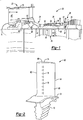
- FIG. 1 schematically illustrates a gas turbine engine 20.
- the gas turbine engine 20 is disclosed herein as a two-spool turbofan that generally incorporates a fan section 22, a compressor section 24, a combustor section 26 and a turbine section 28.
- Alternative engines might include an augmentor section (not shown) among other systems or features.
- the fan section 22 drives air along a bypass flow path B in a bypass duct defined within a nacelle 15, while the compressor section 24 drives air along a core flow path C for compression and communication into the combustor section 26 then expansion through the turbine section 28.
- the exemplary engine 20 generally includes a low speed spool 30 and a high speed spool 32 mounted for rotation about an engine central longitudinal axis A relative to an engine static structure 36 via several bearing systems 38. It should be understood that various bearing systems 38 at various locations may alternatively or additionally be provided, and the location of bearing systems 38 may be varied as appropriate to the application.
- the low speed spool 30 generally includes an inner shaft 40 that interconnects a fan 42, a first (or low) pressure compressor 44 and a first (or low) pressure turbine 46.
- the inner shaft 40 is connected to the fan 42 through a speed change mechanism, which in exemplary gas turbine engine 20 is illustrated as a geared architecture 48 to drive the fan 42 at a lower speed than the low speed spool 30.
- the high speed spool 32 includes an outer shaft 50 that interconnects a second (or high) pressure compressor 52 and a second (or high) pressure turbine 54.
- a combustor 56 is arranged in exemplary gas turbine 20 between the high pressure compressor 52 and the high pressure turbine 54.
- a mid-turbine frame 57 of the engine static structure 36 is arranged generally between the high pressure turbine 54 and the low pressure turbine 46.
- the mid-turbine frame 57 further supports bearing systems 38 in the turbine section 28.
- the inner shaft 40 and the outer shaft 50 are concentric and rotate via bearing systems 38 about the engine central longitudinal axis A which is collinear with their longitudinal axes.
- the core airflow is compressed by the low pressure compressor 44 then the high pressure compressor 52, mixed and burned with fuel in the combustor 56, then expanded over the high pressure turbine 54 and low pressure turbine 46.
- the mid-turbine frame 57 includes airfoils 59 which are in the core airflow path C.
- the turbines 46, 54 rotationally drive the respective low speed spool 30 and high speed spool 32 in response to the expansion.
- gear system 48 may be located aft of combustor section 26 or even aft of turbine section 28, and fan section 22 may be positioned forward or aft of the location of gear system 48.
- the engine 20 in one example is a high-bypass geared aircraft engine.
- the engine 20 bypass ratio is greater than about six (6), with an example embodiment being greater than about ten (10)
- the geared architecture 48 is an epicyclic gear train, such as a planetary gear system or other gear system, with a gear reduction ratio of greater than about 2.3
- the low pressure turbine 46 has a pressure ratio that is greater than about five.
- the engine 20 bypass ratio is greater than about ten (10:1)
- the fan diameter is significantly larger than that of the low pressure compressor 44
- the low pressure turbine 46 has a pressure ratio that is greater than about five 5:1.
- Low pressure turbine 46 pressure ratio is pressure measured prior to inlet of low pressure turbine 46 as related to the pressure at the outlet of the low pressure turbine 46 prior to an exhaust nozzle.
- the geared architecture 48 may be an epicycle gear train, such as a planetary gear system or other gear system, with a gear reduction ratio of greater than about 2.3:1. It should be understood, however, that the above parameters are only exemplary of one embodiment of a geared architecture engine and that the present invention is applicable to other gas turbine engines including direct drive turbofans.
- the fan section 22 of the engine 20 is designed for a particular flight condition -- typically cruise at about 0.8 Mach and about 10,668 meters (35,000 feet).
- 'TSFC' Thrust Specific Fuel Consumption
- Low fan pressure ratio is the pressure ratio across the fan blade alone, without a Fan Exit Guide Vane (“FEGV”) system.
- the low fan pressure ratio as disclosed herein according to one non-limiting embodiment is less than about 1.45.
- "Low corrected fan tip speed” is the actual fan tip speed in meters/second (ft/sec) divided by an industry standard temperature correction of [(Tram K) / (288.2 K)] 0.5 ([(Tram °R) / (518.7 °R)] 0.5 ).
- the "Low corrected fan tip speed" as disclosed herein according to one non-limiting embodiment is less than about 350.5 m/s (1150 ft / second).
- the example gas turbine engine includes fan 42 that comprises in one non-limiting embodiment less than about twenty-six (26) fan blades. In another non-limiting embodiment, fan section 22 includes less than about twenty (20) fan blades. Moreover, in one disclosed embodiment low pressure turbine 46 includes no more than about six (6) turbine rotors schematically indicated at 34. In another non-limiting example embodiment low pressure turbine 46 includes about three (3) turbine rotors. A ratio between number of fan blades 42 and the number of low pressure turbine rotors is between about 3.3 and about 8.6. The example low pressure turbine 46 provides the driving power to rotate fan section 22 and therefore the relationship between the number of turbine rotors 34 in low pressure turbine 46 and number of blades 42 in fan section 22 disclose an example gas turbine engine 20 with increased power transfer efficiency.
- FIG 2 is a perspective view of a blade 60, such as a rotor airfoil, for the gas turbine engine 20, as shown in Figure 1 , or for another turbomachine.
- the blade 60 extends axially from a leading edge 62 to a trailing edge 64, defining a pressure sidewall 66 and a suction sidewall 68.
- the pressure and suction sidewalls 66, 68 form the major opposing surfaces or walls of the blade 60, extending axially between the leading edge 62 and trailing edge 64, and radially outward from a root section 70, adjacent inner diameter (ID) platform 72, to a distal end 74 opposite the ID platform 72.
- the distal end 74 may include a shroud forming an outer diameter (OD) platform.
- Cooling passages 76 are located on one or more surfaces of the blade 60. In the illustrated example, the cooling passages 76 are located along the pressure sidewall 66 of the blade 60. In another example, the cooling passages 76 could be located adjacent the leading edge 62, the trailing edge 64, the pressure sidewall 66, the suction sidewall 68, or a combination thereof.
- FIG 3 is a perspective view of an example vane 80, such as a stator airfoil, for the gas turbine engine 20, as shown in Figure 1 , or for another turbomachine.
- the vane 80 extends axially from a leading edge 82 to a trailing edge 84, defining pressure sidewall 86 (front) and suction sidewall 88 (back) therebetween.
- the pressure and suction sidewalls 86, 88 extend from an ID platform 92 to an outer diameter (OD) platform 94.
- the cooling passages 76 are provided along one or more surfaces of the airfoil 80, for example the leading or trailing edge 82, 84, the pressure (concave) sidewall 86, the suction (convex) sidewall 88, or a combination thereof.
- the blade 60 and the vane 80 are formed of high strength, heat resistant materials such as high temperature alloys and superalloys, and are provided with thermal and erosion-resistant coatings.
- the blade 60 and the vane 80 utilize the internal cooling passages 76 to reduce thermal fatigue and wear, and to prevent melting when exposed to hot gas flow in the higher temperature regions of the gas turbine engine 20 or other turbomachine.
- the cooling passages 76 deliver cooling fluid (e.g., steam or air from a compressor) through the outer walls of the blade and vane 60, 80 creating a thin layer (or film) of cooling fluid to protect the outer (gas path) surfaces from high temperature flow.
- the pressure sidewall 66 includes an inner wall surface 96 and an outer wall surface 98 that are transverse to the cooling passages 76.
- the pressure sidewall 66 is metallic and the outer wall surface 98 can include coating layers such as a thermal barrier coating or a bonding layer.
- the cooling passages 76 are oriented so that their inlets are positioned on the inner wall surface 96 and their outlets are positioned on the outer wall surface 98.
- the outer wall surface 98 is in proximity to high temperature gases (e.g., combustion gases, hot air). Cooling airflow is delivered inside the pressure sidewall 66 where it exits an interior of the blade 60 through the cooling passages 76 and forms a cooling film on the outer wall surface 98.
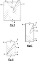
- Each of the cooling passages 76 include a metering portion 102 having a generally cylindrical cross section with a machined surface and a diffusion portion 100 having a cast surface.
- the diffusion portion 100 transitions between a cylindrical cross section at an inlet to a triangular cross section adjacent an outlet 104 to the diffusion portion 100.
- the outlet 104 to the diffusion portion 100 is triangular in the illustrated example, the outlet 104 to the diffusion portion 100 can be any shape as long as the outlet has a larger cross-sectional area than the inlet to the diffusion portion 100.
- the metering portion 102 includes an inlet adjacent the inner wall surface 96 to allow cooling airflow to flow into the cooling passage 76 from internal passages 106 in the blade 60.
- the cooling air flows out of the internal passages 106 and flows through the metering section 102 the diffusion portion 100 to form a cooling film over the blade 60.
- the cooling passages 76 can be arranged in a linear row on pressure sidewall 66 and positioned axially so that the cooling air flows in substantially the same direction longitudinally as the high temperature gases flowing past the pressure sidewall 66.
- the cooling passages 76 can also be located in a staggered formation or other formation on the pressure sidewall 66.
- the cooling holes 76 are described in relation to the blade 60, the cooling holes 76 in the vane 80 are similar to the cooling holes 76 in the blade 60 except where described below or shown in the Figures.
- the cooling passages 76 can be located on a variety of suitable components such as turbine vanes and blades, combustors, blade outer air seals, augmentors, and etc.
- the cooling passages 76 can be located on the pressure sidewalls 66, 86 or suction sidewalls 68, 88 of the blades 60 and the vanes 80, respectively.
- the cooling passages 76 can also be located on a tip or platforms of the blade 60 or vane 80.
- the cooling passages 76 are formed during casting process and a machining process.
- the cooling passages 76 could also be formed during a consolidation process such as is produced from an additive manufacturing process such as powder bed laser sintering and a machining process.
- Figure 6 illustrates a casting or consolidated part for the pressure sidewall 66.
- the casting includes a ceramic shell 110 located adjacent the outer wall surface 98 and a ceramic core 112 located adjacent the inner wall surface 96. Prior to casting, a wax core may be located in place of the pressure sidewall 66 and replaced by the casting material during casting.
- the ceramic shell 110 includes a diffuser protrusion 114 that is in the shape of the diffusion portion 100 of the cooling passage 76, such that when the pressure sidewall 66 is cast, the diffusion portion 100 of the cooling passage 76 is formed.
- a diffuser protrusion 114 that is in the shape of the diffusion portion 100 of the cooling passage 76, such that when the pressure sidewall 66 is cast, the diffusion portion 100 of the cooling passage 76 is formed.
- the diffusion portion 100 of the cooling passage 76 is formed without the metering portion 102.
- the metering portion 102 is then formed by a simple machining process to complete cooling passage 76 as shown in Figure 8 .
- a nest key 108 is located adjacent the diffuser portion 100.
- the nest key 108 is formed during the casting process or by a separated machining process.
- a portion of the diffusion portion 100 is used as the nest key 108.
- the nest key 108 is used as a locating feature to ensure that the metering portion 102 is properly aligned with the diffusion portion 100 to maximize flow through the cooling passage 76 by reducing mismatch between the metering portion 102 and the diffusion portion 100.
- Figures 6-8 illustrate a method of forming the cooling passage 76 in the pressure sidewall 66 of the blade 60
- suitable components such as turbine vanes and blades, combustors, blade outer air seals, augmentors, and etc.
Claims (13)
- Composant de moteur à turbine à gaz (60,80), comprenant :une paroi (66 ; 86) comportant une première surface (96) et une seconde surface (98) opposée à la première surface (96) ; etune pluralité de passages de refroidissement (76) s'étendant entre la première surface (96) et la seconde surface (98) comportant chacun une partie de dosage (102) et une partie de diffusion (100), dans lequel la partie de diffusion (100) comporte une surface coulée ou telle que consolidée ayant une croissance continue de grains cristallins,dans lequel la partie de dosage (102) est adjacente à la première surface (96) et la partie de diffusion (100) est adjacente à la seconde surface (98) ; etla partie de diffusion (100) passe entre une entrée cylindrique et une sortie non cylindrique (104).
- Composant selon la revendication 1, comprenant en outre un élément de positionnement (108) adjacent à la partie de diffusion (100) pour positionner un outil afin d'usiner la partie de dosage (102).
- Composant selon une quelconque revendication précédente, dans lequel la partie de diffusion (100) comporte une zone de section transversale croissante.
- Composant selon une quelconque revendication précédente, dans lequel la partie de dosage (102) comporte une surface usinée.
- Composant selon une quelconque revendication précédente, dans lequel au moins l'une de la partie de dosage (102) et de la partie de diffusion (100) s'étend transversalement jusqu'à la première surface (96) ou la seconde surface (98).
- Composant selon une quelconque revendication précédente, comprenant en outre un moule de coulée (110) ayant une pluralité de saillies de diffusion de coulée (114) pour former la pluralité de parties de diffusion (100).
- Procédé de formation d'un passage de refroidissement (76) dans un composant de turbine à gaz (60 ; 80) comprenant :le coulage d'une pluralité de parties de diffusion (100) dans un composant (60 ; 80) pour permettre une croissance continue de grains cristallins sur une surface de chaque partie de diffusion (100) ; etla formation d'une pluralité de parties de dosage (102) au moins partiellement alignée avec une partie correspondante de la pluralité de parties de diffusion (100) dans le composant (60 ; 80),dans lequel la pluralité de parties de dosage (102) est adjacente à la première surface (96) et la pluralité de parties de diffusion (100) est adjacente à la seconde surface (98) ; etla partie de diffusion (100) passe entre une entrée cylindrique et une sortie non cylindrique (104).
- Procédé selon la revendication 7, dans lequel la pluralité de parties de dosage (102) est formée en utilisant un processus d'usinage.
- Procédé selon la revendication 7, dans lequel le composant (60 ; 80) comporte une paroi (66 ; 86) ayant une première surface (96) opposée à une seconde surface (98).
- Procédé selon la revendication 9, dans lequel la première surface (96) est située sur un côté intérieur du composant (60 ; 80) et la seconde surface (98) est située sur un côté extérieur du composant (60 ; 80).
- Procédé selon l'une quelconque des revendications 7 à 10, dans lequel l'au moins une partie de diffusion (100) comporte une zone de section transversale croissante.
- Procédé selon l'une quelconque des revendications 7 à 11, comprenant en outre le positionnement d'un outil pour former la pluralité de parties de dosage (102) par rapport à la partie de diffusion (100) avec un élément de positionnement (108) adjacent à chacune de la pluralité de parties de diffusion (100).
- Procédé selon l'une quelconque des revendications 7 à 12, comprenant en outre la formation d'un moule (110) ayant une pluralité de saillies de diffusion (114) pour former la pluralité de parties de diffusion (100).
Applications Claiming Priority (1)
| Application Number | Priority Date | Filing Date | Title |
|---|---|---|---|
| US14/682,207 US20160298462A1 (en) | 2015-04-09 | 2015-04-09 | Cooling passages for a gas turbine engine component |
Publications (3)
| Publication Number | Publication Date |
|---|---|
| EP3078807A1 EP3078807A1 (fr) | 2016-10-12 |
| EP3078807B1 true EP3078807B1 (fr) | 2020-03-11 |
| EP3078807B2 EP3078807B2 (fr) | 2023-01-25 |
Family
ID=55699523
Family Applications (1)
| Application Number | Title | Priority Date | Filing Date |
|---|---|---|---|
| EP16164214.5A Active EP3078807B2 (fr) | 2015-04-09 | 2016-04-07 | Passages de refroidissement pour composant de moteur à turbine à gaz |
Country Status (2)
| Country | Link |
|---|---|
| US (1) | US20160298462A1 (fr) |
| EP (1) | EP3078807B2 (fr) |
Families Citing this family (5)
| Publication number | Priority date | Publication date | Assignee | Title |
|---|---|---|---|---|
| US20160090843A1 (en) * | 2014-09-30 | 2016-03-31 | General Electric Company | Turbine components with stepped apertures |
| US11000925B2 (en) | 2018-09-21 | 2021-05-11 | Raytheon Technologies Corporation | Method of forming cooling holes |
| US11220917B1 (en) | 2020-09-03 | 2022-01-11 | Raytheon Technologies Corporation | Diffused cooling arrangement for gas turbine engine components |
| US20230047576A1 (en) * | 2021-08-13 | 2023-02-16 | Raytheon Technologies Corporation | Forming and/or inspecting cooling aperture(s) in a turbine engine component |
| US11913119B2 (en) * | 2021-08-13 | 2024-02-27 | Rtx Corporation | Forming cooling aperture(s) in a turbine engine component |
Citations (4)
| Publication number | Priority date | Publication date | Assignee | Title |
|---|---|---|---|---|
| WO2002049795A1 (fr) * | 2000-12-20 | 2002-06-27 | Chromalloy Gas Turbine Corporation | Usinage laser de trous de refroidissement dans des composants de turbine a gaz |
| EP1813365A1 (fr) | 2006-01-27 | 2007-08-01 | Snecma | Procédé de fabrication de pièce de turbomachine comportant des orifices d'évacuation d'air de refroidissement |
| US7510376B2 (en) | 2005-08-25 | 2009-03-31 | General Electric Company | Skewed tip hole turbine blade |
| US20130139990A1 (en) | 2011-12-06 | 2013-06-06 | Michael Appleby | Systems, Devices, and/or Methods for Producing Holes |
Family Cites Families (29)
| Publication number | Priority date | Publication date | Assignee | Title |
|---|---|---|---|---|
| US3875038A (en) * | 1972-04-19 | 1975-04-01 | Gen Electric | Electrolytic machining apparatus |
| US4197443A (en) * | 1977-09-19 | 1980-04-08 | General Electric Company | Method and apparatus for forming diffused cooling holes in an airfoil |
| US4684323A (en) * | 1985-12-23 | 1987-08-04 | United Technologies Corporation | Film cooling passages with curved corners |
| US4664597A (en) * | 1985-12-23 | 1987-05-12 | United Technologies Corporation | Coolant passages with full coverage film cooling slot |
| US4672727A (en) * | 1985-12-23 | 1987-06-16 | United Technologies Corporation | Method of fabricating film cooling slot in a hollow airfoil |
| US4653983A (en) * | 1985-12-23 | 1987-03-31 | United Technologies Corporation | Cross-flow film cooling passages |
| US4705455A (en) * | 1985-12-23 | 1987-11-10 | United Technologies Corporation | Convergent-divergent film coolant passage |
| US4650949A (en) * | 1985-12-23 | 1987-03-17 | United Technologies Corporation | Electrode for electrical discharge machining film cooling passages in an airfoil |
| US4922076A (en) * | 1987-06-01 | 1990-05-01 | Technical Manufacturing Systems, Inc. | Electro-discharge machining electrode |
| US5605639A (en) * | 1993-12-21 | 1997-02-25 | United Technologies Corporation | Method of producing diffusion holes in turbine components by a multiple piece electrode |
| US5609779A (en) * | 1996-05-15 | 1997-03-11 | General Electric Company | Laser drilling of non-circular apertures |
| EP0945593B1 (fr) * | 1998-03-23 | 2003-05-07 | ALSTOM (Switzerland) Ltd | Trou de refroidissement pelliculaire |
| EP0950463B1 (fr) * | 1998-03-23 | 2002-01-23 | Alstom | Perforation non-circulaire de refroidissement et procédé pour sa fabrication |
| US6362446B1 (en) * | 1999-08-02 | 2002-03-26 | General Electric Company | Method for drilling hollow components |
| US6243948B1 (en) * | 1999-11-18 | 2001-06-12 | General Electric Company | Modification and repair of film cooling holes in gas turbine engine components |
| US6918742B2 (en) * | 2002-09-05 | 2005-07-19 | Siemens Westinghouse Power Corporation | Combustion turbine with airfoil having multi-section diffusion cooling holes and methods of making same |
| US7041933B2 (en) * | 2003-04-14 | 2006-05-09 | Meyer Tool, Inc. | Complex hole shaping |
| US6897401B2 (en) * | 2003-07-31 | 2005-05-24 | United Technologies Corporation | Non-separating diffuser for holes produced by a two step process |
| US7008186B2 (en) * | 2003-09-17 | 2006-03-07 | General Electric Company | Teardrop film cooled blade |
| JP3997986B2 (ja) * | 2003-12-19 | 2007-10-24 | 株式会社Ihi | 冷却タービン部品、及び冷却タービン翼 |
| US7328580B2 (en) * | 2004-06-23 | 2008-02-12 | General Electric Company | Chevron film cooled wall |
| US7172012B1 (en) * | 2004-07-14 | 2007-02-06 | United Technologies Corporation | Investment casting |
| US7374401B2 (en) * | 2005-03-01 | 2008-05-20 | General Electric Company | Bell-shaped fan cooling holes for turbine airfoil |
| US7249934B2 (en) * | 2005-08-31 | 2007-07-31 | General Electric Company | Pattern cooled turbine airfoil |
| US7214901B1 (en) * | 2006-01-17 | 2007-05-08 | General Electric Company | Duplex electrical discharge machining |
| US7766617B1 (en) * | 2007-03-06 | 2010-08-03 | Florida Turbine Technologies, Inc. | Transpiration cooled turbine airfoil |
| US7980819B2 (en) * | 2007-03-14 | 2011-07-19 | United Technologies Corporation | Cast features for a turbine engine airfoil |
| US8905713B2 (en) * | 2010-05-28 | 2014-12-09 | General Electric Company | Articles which include chevron film cooling holes, and related processes |
| US8707713B2 (en) * | 2012-02-15 | 2014-04-29 | United Technologies Corporation | Cooling hole with crenellation features |
-
2015
- 2015-04-09 US US14/682,207 patent/US20160298462A1/en not_active Abandoned
-
2016
- 2016-04-07 EP EP16164214.5A patent/EP3078807B2/fr active Active
Patent Citations (4)
| Publication number | Priority date | Publication date | Assignee | Title |
|---|---|---|---|---|
| WO2002049795A1 (fr) * | 2000-12-20 | 2002-06-27 | Chromalloy Gas Turbine Corporation | Usinage laser de trous de refroidissement dans des composants de turbine a gaz |
| US7510376B2 (en) | 2005-08-25 | 2009-03-31 | General Electric Company | Skewed tip hole turbine blade |
| EP1813365A1 (fr) | 2006-01-27 | 2007-08-01 | Snecma | Procédé de fabrication de pièce de turbomachine comportant des orifices d'évacuation d'air de refroidissement |
| US20130139990A1 (en) | 2011-12-06 | 2013-06-06 | Michael Appleby | Systems, Devices, and/or Methods for Producing Holes |
Also Published As
| Publication number | Publication date |
|---|---|
| EP3078807B2 (fr) | 2023-01-25 |
| US20160298462A1 (en) | 2016-10-13 |
| EP3078807A1 (fr) | 2016-10-12 |
Similar Documents
| Publication | Publication Date | Title |
|---|---|---|
| US11035236B2 (en) | Baffle for a component of a gas turbine engine | |
| US10808546B2 (en) | Gas turbine engine airfoil trailing edge suction side cooling | |
| EP2867472B1 (fr) | Aube statorique de turbine | |
| EP3056674B1 (fr) | Article possédant un passage de refroidissement avec profil ondulé | |
| EP3047119B1 (fr) | Configuration de refroidissement pour un composant de moteur | |
| US20200149413A1 (en) | Gas turbine engine airfoil with wishbone baffle cooling scheme | |
| US9334755B2 (en) | Airfoil with variable trip strip height | |
| EP3078807B1 (fr) | Passages de refroidissement pour composant de moteur à turbine à gaz | |
| EP2993304B1 (fr) | Composant de moteur à turbine à gaz avec trou formant un film de refroidissement | |
| US10465542B2 (en) | Gas turbine engine turbine vane baffle and serpentine cooling passage | |
| EP2997231B1 (fr) | Un composant de moteur à turbine à gaz etant une aube et un noyau interrelié pour la production d'un composant de moteur à turbine à gaz etant une aube | |
| EP3461993B1 (fr) | Aube de moteur à turbine à gaz | |
| EP3051066B1 (fr) | Noyau de coulée comprenant des extensions décalées | |
| EP2998511B1 (fr) | Canal de refroidissement avec des caractéristiques de surface | |
| EP3061913B1 (fr) | Configuration de refroidissement d'aube de moteur à turbine à gaz avec séparateurs de gradient de pression | |
| EP3406851B1 (fr) | Composant pour un moteur à turbine à gaz et procédé de former un agencement de noyaux |
Legal Events
| Date | Code | Title | Description |
|---|---|---|---|
| PUAI | Public reference made under article 153(3) epc to a published international application that has entered the european phase |
Free format text: ORIGINAL CODE: 0009012 |
|
| AK | Designated contracting states |
Kind code of ref document: A1 Designated state(s): AL AT BE BG CH CY CZ DE DK EE ES FI FR GB GR HR HU IE IS IT LI LT LU LV MC MK MT NL NO PL PT RO RS SE SI SK SM TR |
|
| AX | Request for extension of the european patent |
Extension state: BA ME |
|
| RAP1 | Party data changed (applicant data changed or rights of an application transferred) |
Owner name: UNITED TECHNOLOGIES CORPORATION |
|
| STAA | Information on the status of an ep patent application or granted ep patent |
Free format text: STATUS: REQUEST FOR EXAMINATION WAS MADE |
|
| 17P | Request for examination filed |
Effective date: 20170411 |
|
| RBV | Designated contracting states (corrected) |
Designated state(s): AL AT BE BG CH CY CZ DE DK EE ES FI FR GB GR HR HU IE IS IT LI LT LU LV MC MK MT NL NO PL PT RO RS SE SI SK SM TR |
|
| STAA | Information on the status of an ep patent application or granted ep patent |
Free format text: STATUS: EXAMINATION IS IN PROGRESS |
|
| 17Q | First examination report despatched |
Effective date: 20181217 |
|
| RIC1 | Information provided on ipc code assigned before grant |
Ipc: B22C 7/00 20060101ALI20190807BHEP Ipc: B22C 9/24 20060101ALI20190807BHEP Ipc: F02C 7/18 20060101ALI20190807BHEP Ipc: F01D 11/08 20060101ALI20190807BHEP Ipc: F02C 3/00 20060101ALI20190807BHEP Ipc: F01D 5/18 20060101AFI20190807BHEP Ipc: F01D 25/12 20060101ALI20190807BHEP Ipc: F01D 9/04 20060101ALI20190807BHEP |
|
| GRAP | Despatch of communication of intention to grant a patent |
Free format text: ORIGINAL CODE: EPIDOSNIGR1 |
|
| STAA | Information on the status of an ep patent application or granted ep patent |
Free format text: STATUS: GRANT OF PATENT IS INTENDED |
|
| INTG | Intention to grant announced |
Effective date: 20190924 |
|
| GRAS | Grant fee paid |
Free format text: ORIGINAL CODE: EPIDOSNIGR3 |
|
| GRAA | (expected) grant |
Free format text: ORIGINAL CODE: 0009210 |
|
| STAA | Information on the status of an ep patent application or granted ep patent |
Free format text: STATUS: THE PATENT HAS BEEN GRANTED |
|
| AK | Designated contracting states |
Kind code of ref document: B1 Designated state(s): AL AT BE BG CH CY CZ DE DK EE ES FI FR GB GR HR HU IE IS IT LI LT LU LV MC MK MT NL NO PL PT RO RS SE SI SK SM TR |
|
| REG | Reference to a national code |
Ref country code: GB Ref legal event code: FG4D |
|
| REG | Reference to a national code |
Ref country code: CH Ref legal event code: EP |
|
| REG | Reference to a national code |
Ref country code: AT Ref legal event code: REF Ref document number: 1243371 Country of ref document: AT Kind code of ref document: T Effective date: 20200315 |
|
| REG | Reference to a national code |
Ref country code: DE Ref legal event code: R096 Ref document number: 602016031354 Country of ref document: DE |
|
| REG | Reference to a national code |
Ref country code: IE Ref legal event code: FG4D |
|
| PG25 | Lapsed in a contracting state [announced via postgrant information from national office to epo] |
Ref country code: NO Free format text: LAPSE BECAUSE OF FAILURE TO SUBMIT A TRANSLATION OF THE DESCRIPTION OR TO PAY THE FEE WITHIN THE PRESCRIBED TIME-LIMIT Effective date: 20200611 Ref country code: RS Free format text: LAPSE BECAUSE OF FAILURE TO SUBMIT A TRANSLATION OF THE DESCRIPTION OR TO PAY THE FEE WITHIN THE PRESCRIBED TIME-LIMIT Effective date: 20200311 Ref country code: FI Free format text: LAPSE BECAUSE OF FAILURE TO SUBMIT A TRANSLATION OF THE DESCRIPTION OR TO PAY THE FEE WITHIN THE PRESCRIBED TIME-LIMIT Effective date: 20200311 |
|
| REG | Reference to a national code |
Ref country code: NL Ref legal event code: MP Effective date: 20200311 |
|
| PG25 | Lapsed in a contracting state [announced via postgrant information from national office to epo] |
Ref country code: GR Free format text: LAPSE BECAUSE OF FAILURE TO SUBMIT A TRANSLATION OF THE DESCRIPTION OR TO PAY THE FEE WITHIN THE PRESCRIBED TIME-LIMIT Effective date: 20200612 Ref country code: HR Free format text: LAPSE BECAUSE OF FAILURE TO SUBMIT A TRANSLATION OF THE DESCRIPTION OR TO PAY THE FEE WITHIN THE PRESCRIBED TIME-LIMIT Effective date: 20200311 Ref country code: SE Free format text: LAPSE BECAUSE OF FAILURE TO SUBMIT A TRANSLATION OF THE DESCRIPTION OR TO PAY THE FEE WITHIN THE PRESCRIBED TIME-LIMIT Effective date: 20200311 Ref country code: LV Free format text: LAPSE BECAUSE OF FAILURE TO SUBMIT A TRANSLATION OF THE DESCRIPTION OR TO PAY THE FEE WITHIN THE PRESCRIBED TIME-LIMIT Effective date: 20200311 Ref country code: BG Free format text: LAPSE BECAUSE OF FAILURE TO SUBMIT A TRANSLATION OF THE DESCRIPTION OR TO PAY THE FEE WITHIN THE PRESCRIBED TIME-LIMIT Effective date: 20200611 |
|
| REG | Reference to a national code |
Ref country code: LT Ref legal event code: MG4D |
|
| PG25 | Lapsed in a contracting state [announced via postgrant information from national office to epo] |
Ref country code: NL Free format text: LAPSE BECAUSE OF FAILURE TO SUBMIT A TRANSLATION OF THE DESCRIPTION OR TO PAY THE FEE WITHIN THE PRESCRIBED TIME-LIMIT Effective date: 20200311 |
|
| PG25 | Lapsed in a contracting state [announced via postgrant information from national office to epo] |
Ref country code: EE Free format text: LAPSE BECAUSE OF FAILURE TO SUBMIT A TRANSLATION OF THE DESCRIPTION OR TO PAY THE FEE WITHIN THE PRESCRIBED TIME-LIMIT Effective date: 20200311 Ref country code: LT Free format text: LAPSE BECAUSE OF FAILURE TO SUBMIT A TRANSLATION OF THE DESCRIPTION OR TO PAY THE FEE WITHIN THE PRESCRIBED TIME-LIMIT Effective date: 20200311 Ref country code: IS Free format text: LAPSE BECAUSE OF FAILURE TO SUBMIT A TRANSLATION OF THE DESCRIPTION OR TO PAY THE FEE WITHIN THE PRESCRIBED TIME-LIMIT Effective date: 20200711 Ref country code: CZ Free format text: LAPSE BECAUSE OF FAILURE TO SUBMIT A TRANSLATION OF THE DESCRIPTION OR TO PAY THE FEE WITHIN THE PRESCRIBED TIME-LIMIT Effective date: 20200311 Ref country code: RO Free format text: LAPSE BECAUSE OF FAILURE TO SUBMIT A TRANSLATION OF THE DESCRIPTION OR TO PAY THE FEE WITHIN THE PRESCRIBED TIME-LIMIT Effective date: 20200311 Ref country code: SK Free format text: LAPSE BECAUSE OF FAILURE TO SUBMIT A TRANSLATION OF THE DESCRIPTION OR TO PAY THE FEE WITHIN THE PRESCRIBED TIME-LIMIT Effective date: 20200311 Ref country code: PT Free format text: LAPSE BECAUSE OF FAILURE TO SUBMIT A TRANSLATION OF THE DESCRIPTION OR TO PAY THE FEE WITHIN THE PRESCRIBED TIME-LIMIT Effective date: 20200805 Ref country code: SM Free format text: LAPSE BECAUSE OF FAILURE TO SUBMIT A TRANSLATION OF THE DESCRIPTION OR TO PAY THE FEE WITHIN THE PRESCRIBED TIME-LIMIT Effective date: 20200311 |
|
| REG | Reference to a national code |
Ref country code: AT Ref legal event code: MK05 Ref document number: 1243371 Country of ref document: AT Kind code of ref document: T Effective date: 20200311 |
|
| REG | Reference to a national code |
Ref country code: CH Ref legal event code: PL |
|
| REG | Reference to a national code |
Ref country code: DE Ref legal event code: R026 Ref document number: 602016031354 Country of ref document: DE |
|
| PLBI | Opposition filed |
Free format text: ORIGINAL CODE: 0009260 |
|
| PG25 | Lapsed in a contracting state [announced via postgrant information from national office to epo] |
Ref country code: MC Free format text: LAPSE BECAUSE OF FAILURE TO SUBMIT A TRANSLATION OF THE DESCRIPTION OR TO PAY THE FEE WITHIN THE PRESCRIBED TIME-LIMIT Effective date: 20200311 |
|
| PLAX | Notice of opposition and request to file observation + time limit sent |
Free format text: ORIGINAL CODE: EPIDOSNOBS2 |
|
| 26 | Opposition filed |
Opponent name: SAFRAN AIRCRAFT ENGINES Effective date: 20201210 |
|
| PG25 | Lapsed in a contracting state [announced via postgrant information from national office to epo] |
Ref country code: IT Free format text: LAPSE BECAUSE OF FAILURE TO SUBMIT A TRANSLATION OF THE DESCRIPTION OR TO PAY THE FEE WITHIN THE PRESCRIBED TIME-LIMIT Effective date: 20200311 Ref country code: LI Free format text: LAPSE BECAUSE OF NON-PAYMENT OF DUE FEES Effective date: 20200430 Ref country code: ES Free format text: LAPSE BECAUSE OF FAILURE TO SUBMIT A TRANSLATION OF THE DESCRIPTION OR TO PAY THE FEE WITHIN THE PRESCRIBED TIME-LIMIT Effective date: 20200311 Ref country code: LU Free format text: LAPSE BECAUSE OF NON-PAYMENT OF DUE FEES Effective date: 20200407 Ref country code: CH Free format text: LAPSE BECAUSE OF NON-PAYMENT OF DUE FEES Effective date: 20200430 Ref country code: AT Free format text: LAPSE BECAUSE OF FAILURE TO SUBMIT A TRANSLATION OF THE DESCRIPTION OR TO PAY THE FEE WITHIN THE PRESCRIBED TIME-LIMIT Effective date: 20200311 Ref country code: DK Free format text: LAPSE BECAUSE OF FAILURE TO SUBMIT A TRANSLATION OF THE DESCRIPTION OR TO PAY THE FEE WITHIN THE PRESCRIBED TIME-LIMIT Effective date: 20200311 |
|
| REG | Reference to a national code |
Ref country code: BE Ref legal event code: MM Effective date: 20200430 |
|
| PG25 | Lapsed in a contracting state [announced via postgrant information from national office to epo] |
Ref country code: BE Free format text: LAPSE BECAUSE OF NON-PAYMENT OF DUE FEES Effective date: 20200430 Ref country code: SI Free format text: LAPSE BECAUSE OF FAILURE TO SUBMIT A TRANSLATION OF THE DESCRIPTION OR TO PAY THE FEE WITHIN THE PRESCRIBED TIME-LIMIT Effective date: 20200311 Ref country code: PL Free format text: LAPSE BECAUSE OF FAILURE TO SUBMIT A TRANSLATION OF THE DESCRIPTION OR TO PAY THE FEE WITHIN THE PRESCRIBED TIME-LIMIT Effective date: 20200311 |
|
| RAP2 | Party data changed (patent owner data changed or rights of a patent transferred) |
Owner name: RAYTHEON TECHNOLOGIES CORPORATION |
|
| PG25 | Lapsed in a contracting state [announced via postgrant information from national office to epo] |
Ref country code: IE Free format text: LAPSE BECAUSE OF NON-PAYMENT OF DUE FEES Effective date: 20200407 |
|
| PLBB | Reply of patent proprietor to notice(s) of opposition received |
Free format text: ORIGINAL CODE: EPIDOSNOBS3 |
|
| PG25 | Lapsed in a contracting state [announced via postgrant information from national office to epo] |
Ref country code: TR Free format text: LAPSE BECAUSE OF FAILURE TO SUBMIT A TRANSLATION OF THE DESCRIPTION OR TO PAY THE FEE WITHIN THE PRESCRIBED TIME-LIMIT Effective date: 20200311 Ref country code: MT Free format text: LAPSE BECAUSE OF FAILURE TO SUBMIT A TRANSLATION OF THE DESCRIPTION OR TO PAY THE FEE WITHIN THE PRESCRIBED TIME-LIMIT Effective date: 20200311 Ref country code: CY Free format text: LAPSE BECAUSE OF FAILURE TO SUBMIT A TRANSLATION OF THE DESCRIPTION OR TO PAY THE FEE WITHIN THE PRESCRIBED TIME-LIMIT Effective date: 20200311 |
|
| PG25 | Lapsed in a contracting state [announced via postgrant information from national office to epo] |
Ref country code: MK Free format text: LAPSE BECAUSE OF FAILURE TO SUBMIT A TRANSLATION OF THE DESCRIPTION OR TO PAY THE FEE WITHIN THE PRESCRIBED TIME-LIMIT Effective date: 20200311 Ref country code: AL Free format text: LAPSE BECAUSE OF FAILURE TO SUBMIT A TRANSLATION OF THE DESCRIPTION OR TO PAY THE FEE WITHIN THE PRESCRIBED TIME-LIMIT Effective date: 20200311 |
|
| REG | Reference to a national code |
Ref country code: DE Ref legal event code: R081 Ref document number: 602016031354 Country of ref document: DE Owner name: RAYTHEON TECHNOLOGIES CORPORATION (N.D.GES.D.S, US Free format text: FORMER OWNER: UNITED TECHNOLOGIES CORPORATION, FARMINGTON, CONN., US |
|
| PUAH | Patent maintained in amended form |
Free format text: ORIGINAL CODE: 0009272 |
|
| STAA | Information on the status of an ep patent application or granted ep patent |
Free format text: STATUS: PATENT MAINTAINED AS AMENDED |
|
| 27A | Patent maintained in amended form |
Effective date: 20230125 |
|
| AK | Designated contracting states |
Kind code of ref document: B2 Designated state(s): AL AT BE BG CH CY CZ DE DK EE ES FI FR GB GR HR HU IE IS IT LI LT LU LV MC MK MT NL NO PL PT RO RS SE SI SK SM TR |
|
| REG | Reference to a national code |
Ref country code: DE Ref legal event code: R102 Ref document number: 602016031354 Country of ref document: DE |
|
| PGFP | Annual fee paid to national office [announced via postgrant information from national office to epo] |
Ref country code: FR Payment date: 20230321 Year of fee payment: 8 |
|
| PGFP | Annual fee paid to national office [announced via postgrant information from national office to epo] |
Ref country code: GB Payment date: 20230322 Year of fee payment: 8 |
|
| P01 | Opt-out of the competence of the unified patent court (upc) registered |
Effective date: 20230520 |
|
| PGFP | Annual fee paid to national office [announced via postgrant information from national office to epo] |
Ref country code: DE Payment date: 20230321 Year of fee payment: 8 |