EP3078645A1 - Gap retention member for glass panel and method for manufacturing same - Google Patents
Gap retention member for glass panel and method for manufacturing same Download PDFInfo
- Publication number
- EP3078645A1 EP3078645A1 EP14867715.6A EP14867715A EP3078645A1 EP 3078645 A1 EP3078645 A1 EP 3078645A1 EP 14867715 A EP14867715 A EP 14867715A EP 3078645 A1 EP3078645 A1 EP 3078645A1
- Authority
- EP
- European Patent Office
- Prior art keywords
- glass plates
- retention member
- glass
- soft portion
- hard portions
- Prior art date
- Legal status (The legal status is an assumption and is not a legal conclusion. Google has not performed a legal analysis and makes no representation as to the accuracy of the status listed.)
- Withdrawn
Links
Images

Classifications
-
- E—FIXED CONSTRUCTIONS
- E06—DOORS, WINDOWS, SHUTTERS, OR ROLLER BLINDS IN GENERAL; LADDERS
- E06B—FIXED OR MOVABLE CLOSURES FOR OPENINGS IN BUILDINGS, VEHICLES, FENCES OR LIKE ENCLOSURES IN GENERAL, e.g. DOORS, WINDOWS, BLINDS, GATES
- E06B3/00—Window sashes, door leaves, or like elements for closing wall or like openings; Layout of fixed or moving closures, e.g. windows in wall or like openings; Features of rigidly-mounted outer frames relating to the mounting of wing frames
- E06B3/66—Units comprising two or more parallel glass or like panes permanently secured together
- E06B3/663—Elements for spacing panes
-
- E—FIXED CONSTRUCTIONS
- E06—DOORS, WINDOWS, SHUTTERS, OR ROLLER BLINDS IN GENERAL; LADDERS
- E06B—FIXED OR MOVABLE CLOSURES FOR OPENINGS IN BUILDINGS, VEHICLES, FENCES OR LIKE ENCLOSURES IN GENERAL, e.g. DOORS, WINDOWS, BLINDS, GATES
- E06B3/00—Window sashes, door leaves, or like elements for closing wall or like openings; Layout of fixed or moving closures, e.g. windows in wall or like openings; Features of rigidly-mounted outer frames relating to the mounting of wing frames
- E06B3/66—Units comprising two or more parallel glass or like panes permanently secured together
- E06B3/673—Assembling the units
- E06B3/67326—Assembling spacer elements with the panes
-
- E—FIXED CONSTRUCTIONS
- E06—DOORS, WINDOWS, SHUTTERS, OR ROLLER BLINDS IN GENERAL; LADDERS
- E06B—FIXED OR MOVABLE CLOSURES FOR OPENINGS IN BUILDINGS, VEHICLES, FENCES OR LIKE ENCLOSURES IN GENERAL, e.g. DOORS, WINDOWS, BLINDS, GATES
- E06B3/00—Window sashes, door leaves, or like elements for closing wall or like openings; Layout of fixed or moving closures, e.g. windows in wall or like openings; Features of rigidly-mounted outer frames relating to the mounting of wing frames
- E06B3/66—Units comprising two or more parallel glass or like panes permanently secured together
- E06B3/663—Elements for spacing panes
- E06B3/66304—Discrete spacing elements, e.g. for evacuated glazing units
-
- C—CHEMISTRY; METALLURGY
- C23—COATING METALLIC MATERIAL; COATING MATERIAL WITH METALLIC MATERIAL; CHEMICAL SURFACE TREATMENT; DIFFUSION TREATMENT OF METALLIC MATERIAL; COATING BY VACUUM EVAPORATION, BY SPUTTERING, BY ION IMPLANTATION OR BY CHEMICAL VAPOUR DEPOSITION, IN GENERAL; INHIBITING CORROSION OF METALLIC MATERIAL OR INCRUSTATION IN GENERAL
- C23F—NON-MECHANICAL REMOVAL OF METALLIC MATERIAL FROM SURFACE; INHIBITING CORROSION OF METALLIC MATERIAL OR INCRUSTATION IN GENERAL; MULTI-STEP PROCESSES FOR SURFACE TREATMENT OF METALLIC MATERIAL INVOLVING AT LEAST ONE PROCESS PROVIDED FOR IN CLASS C23 AND AT LEAST ONE PROCESS COVERED BY SUBCLASS C21D OR C22F OR CLASS C25
- C23F1/00—Etching metallic material by chemical means
-
- E—FIXED CONSTRUCTIONS
- E06—DOORS, WINDOWS, SHUTTERS, OR ROLLER BLINDS IN GENERAL; LADDERS
- E06B—FIXED OR MOVABLE CLOSURES FOR OPENINGS IN BUILDINGS, VEHICLES, FENCES OR LIKE ENCLOSURES IN GENERAL, e.g. DOORS, WINDOWS, BLINDS, GATES
- E06B3/00—Window sashes, door leaves, or like elements for closing wall or like openings; Layout of fixed or moving closures, e.g. windows in wall or like openings; Features of rigidly-mounted outer frames relating to the mounting of wing frames
- E06B3/66—Units comprising two or more parallel glass or like panes permanently secured together
- E06B3/6608—Units comprising two or more parallel glass or like panes permanently secured together without separate spacing elements
-
- E—FIXED CONSTRUCTIONS
- E06—DOORS, WINDOWS, SHUTTERS, OR ROLLER BLINDS IN GENERAL; LADDERS
- E06B—FIXED OR MOVABLE CLOSURES FOR OPENINGS IN BUILDINGS, VEHICLES, FENCES OR LIKE ENCLOSURES IN GENERAL, e.g. DOORS, WINDOWS, BLINDS, GATES
- E06B3/00—Window sashes, door leaves, or like elements for closing wall or like openings; Layout of fixed or moving closures, e.g. windows in wall or like openings; Features of rigidly-mounted outer frames relating to the mounting of wing frames
- E06B3/66—Units comprising two or more parallel glass or like panes permanently secured together
- E06B3/6612—Evacuated glazing units
-
- E—FIXED CONSTRUCTIONS
- E06—DOORS, WINDOWS, SHUTTERS, OR ROLLER BLINDS IN GENERAL; LADDERS
- E06B—FIXED OR MOVABLE CLOSURES FOR OPENINGS IN BUILDINGS, VEHICLES, FENCES OR LIKE ENCLOSURES IN GENERAL, e.g. DOORS, WINDOWS, BLINDS, GATES
- E06B3/00—Window sashes, door leaves, or like elements for closing wall or like openings; Layout of fixed or moving closures, e.g. windows in wall or like openings; Features of rigidly-mounted outer frames relating to the mounting of wing frames
- E06B3/66—Units comprising two or more parallel glass or like panes permanently secured together
- E06B3/663—Elements for spacing panes
- E06B3/66309—Section members positioned at the edges of the glazing unit
-
- E—FIXED CONSTRUCTIONS
- E06—DOORS, WINDOWS, SHUTTERS, OR ROLLER BLINDS IN GENERAL; LADDERS
- E06B—FIXED OR MOVABLE CLOSURES FOR OPENINGS IN BUILDINGS, VEHICLES, FENCES OR LIKE ENCLOSURES IN GENERAL, e.g. DOORS, WINDOWS, BLINDS, GATES
- E06B3/00—Window sashes, door leaves, or like elements for closing wall or like openings; Layout of fixed or moving closures, e.g. windows in wall or like openings; Features of rigidly-mounted outer frames relating to the mounting of wing frames
- E06B3/66—Units comprising two or more parallel glass or like panes permanently secured together
- E06B3/663—Elements for spacing panes
- E06B3/66309—Section members positioned at the edges of the glazing unit
- E06B3/66333—Section members positioned at the edges of the glazing unit of unusual substances, e.g. wood or other fibrous materials, glass or other transparent materials
-
- E—FIXED CONSTRUCTIONS
- E06—DOORS, WINDOWS, SHUTTERS, OR ROLLER BLINDS IN GENERAL; LADDERS
- E06B—FIXED OR MOVABLE CLOSURES FOR OPENINGS IN BUILDINGS, VEHICLES, FENCES OR LIKE ENCLOSURES IN GENERAL, e.g. DOORS, WINDOWS, BLINDS, GATES
- E06B3/00—Window sashes, door leaves, or like elements for closing wall or like openings; Layout of fixed or moving closures, e.g. windows in wall or like openings; Features of rigidly-mounted outer frames relating to the mounting of wing frames
- E06B3/66—Units comprising two or more parallel glass or like panes permanently secured together
- E06B3/663—Elements for spacing panes
- E06B3/66309—Section members positioned at the edges of the glazing unit
- E06B3/66342—Section members positioned at the edges of the glazing unit characterised by their sealed connection to the panes
- E06B3/66357—Soldered connections or the like
-
- E—FIXED CONSTRUCTIONS
- E06—DOORS, WINDOWS, SHUTTERS, OR ROLLER BLINDS IN GENERAL; LADDERS
- E06B—FIXED OR MOVABLE CLOSURES FOR OPENINGS IN BUILDINGS, VEHICLES, FENCES OR LIKE ENCLOSURES IN GENERAL, e.g. DOORS, WINDOWS, BLINDS, GATES
- E06B3/00—Window sashes, door leaves, or like elements for closing wall or like openings; Layout of fixed or moving closures, e.g. windows in wall or like openings; Features of rigidly-mounted outer frames relating to the mounting of wing frames
- E06B3/66—Units comprising two or more parallel glass or like panes permanently secured together
- E06B3/677—Evacuating or filling the gap between the panes ; Equilibration of inside and outside pressure; Preventing condensation in the gap between the panes; Cleaning the gap between the panes
-
- Y—GENERAL TAGGING OF NEW TECHNOLOGICAL DEVELOPMENTS; GENERAL TAGGING OF CROSS-SECTIONAL TECHNOLOGIES SPANNING OVER SEVERAL SECTIONS OF THE IPC; TECHNICAL SUBJECTS COVERED BY FORMER USPC CROSS-REFERENCE ART COLLECTIONS [XRACs] AND DIGESTS
- Y02—TECHNOLOGIES OR APPLICATIONS FOR MITIGATION OR ADAPTATION AGAINST CLIMATE CHANGE
- Y02A—TECHNOLOGIES FOR ADAPTATION TO CLIMATE CHANGE
- Y02A30/00—Adapting or protecting infrastructure or their operation
- Y02A30/24—Structural elements or technologies for improving thermal insulation
- Y02A30/249—Glazing, e.g. vacuum glazing
-
- Y—GENERAL TAGGING OF NEW TECHNOLOGICAL DEVELOPMENTS; GENERAL TAGGING OF CROSS-SECTIONAL TECHNOLOGIES SPANNING OVER SEVERAL SECTIONS OF THE IPC; TECHNICAL SUBJECTS COVERED BY FORMER USPC CROSS-REFERENCE ART COLLECTIONS [XRACs] AND DIGESTS
- Y02—TECHNOLOGIES OR APPLICATIONS FOR MITIGATION OR ADAPTATION AGAINST CLIMATE CHANGE
- Y02B—CLIMATE CHANGE MITIGATION TECHNOLOGIES RELATED TO BUILDINGS, e.g. HOUSING, HOUSE APPLIANCES OR RELATED END-USER APPLICATIONS
- Y02B80/00—Architectural or constructional elements improving the thermal performance of buildings
- Y02B80/22—Glazing, e.g. vaccum glazing
Definitions
- This disclosure relates to a glass panel gap retention member, many of which are to be disposed between a pair of glass plates in manufacturing of a vacuum multilayer glass panel. This disclosure relates also to a method of manufacturing such glass panel gap retention member.
- a vacuum multilayer glass panel comprising a pair of glass plates with their circumferential portions being sealed and depressurized
- the panel is subjected to a compressive force due to the atmospheric pressure from the outside of the glass plates.
- a plurality of gap retention members having a high compression strength are disposed with a predetermined spacing from each other.
- the gap retention members can be displaced or destroyed, or in an even worse case, concentration of load at some limited portion(s) of the glass plates may sometimes cause breakage of the glass plates.
- a gap retention member includes a core material having a high compression strength and a cushioning layer provided at least at one end portion of the core material and made of a soft material such as a soft metal. As the soft material can easily be deformed, the gap retention member can conform to the glass plate more smoothly, thus enhancing the strength of the glass plate against a shearing stress.
- Patent Document 1 Japanese Unexamined Patent Application Publication No. H10-507500
- Such gap retention member is made generally by a mechanical means such as a press work or laser cut on steel material, aluminum material or the like, or an etching work which is a molding or surface treatment utilizing a corrosive action of a chemical agent.
- the etching work has advantages such as no generation of burr, strain, warp etc. which are of some concern in a press work, readiness of shape change via an etching pattern, no need for expensive mold, jig, etc.
- a soft metal is disposed on the outer side of the gap retention member, making of the gap retention member by an etching work is difficult. This is because the soft metal is melted more easily than the core material portion of the gap retention member during the etching work, which makes it difficult to form the soft metal into a desired shape and thickness.
- the present invention has been made in view of the above-described state of the art to provide a glass panel gap retention member capable of retaining a predetermined spacing in a vacuum multilayer glass without compromising its outer appearance and effectively absorbing a positional displacement between the pair of glass plates in their face direction, and a method of manufacturing such glass panel gap retention member.
- a glass panel gap retention member to be disposed between a pair of glass plates when a circumference of a gap formed between the pair of glass plates with their plate faces opposing each other is to be sealed to maintain the gap under a depressurized state
- the glass panel gap retention member comprising: hard portions to contact the pair of glass plates respectively; a soft portion disposed between the hard portions and having a lower hardness than the hard portions; and the soft portion being more susceptible to deformation based on a shearing force effective in a direction along the opposing faces of the glass plates than deformation based on a compressive force effective in a thickness direction perpendicular to the opposing faces of the glass plates.
- the gap retention member With the above-described configuration wherein the soft portion is more susceptible to deformation based on a shearing force effective in the direction along the opposing faces of the glass plates than deformation based on a compressive force effective in a thickness direction perpendicular to the opposing faces of the glass plate, in the gap retention member, deformation thereof in the thickness direction is suppressed.
- the gap retention member With respect to a relative movement between the pair of glass plates, as the soft portion is deformed based on a shearing force, the gap retention member can easily conform to the surfaces of the glass plates. As this lessens the shearing force exerted from the gap retention member to the glass plates along the face direction, breakage of the pair of glass plates will occur less likely.
- the hard portions are formed of stainless steel material and the soft portion is formed of aluminum material which is rolled in the direction along the opposing faces.
- the shape of the outer side members coming into contact with the surfaces of the glass plates can be stable. Whereby, even when there occur change in the glass plate surface from a planar shape to a non-planar shape or vice versa, due to repeated application of load generated from wind pressure or the like to the glass plates for an extended period or local application of a shock thereto, there will occur no plastic deformation in the shape of the hard portions in association therewith and the shape of the hard portions can be stably maintained. Therefore, under a normal condition free from any wind pressure application, no inconvenience such as change in the area of contact between the glass plate and the hard portions will occur and the contact state can always remain the same and the gap retention function can be maintained for an extended period.
- the soft portion is formed of aluminum material which is rolled in the direction along the opposing faces, the soft portion is more susceptible to shearing deformation along the surfaces of the glass plates than compressive deformation in the thickness direction of the glass plates. In this way, with the gap retention member having the above-described configuration, the shearing force effective between the pair of glass plates too can be absorbed easily.
- the hard portions and the soft portion are in contact with each other under a non-bonded state.
- non-bonded state in the above-described arrangement means a simple arrangement such as an arrangement of the hard portions and the soft portion being pressed against each other with an appropriate force.
- the language excludes such arrangement as connecting between the hard portions and the soft portion with using an adhesive agent additionally.
- the hard portions and the soft portion are joined to each other integrally.
- the gap retention member can be handled easily in manufacturing of the vacuum multilayer glass. Moreover, the shape of the gap retention member can be more stable, so that it becomes possible to cause the soft material to provide its deformation property with higher precision.
- the gap retention member having the above-described arrangement can be suitably used in e.g. a vacuum multilayer glass using glass plates having high strength capable of withstanding large bending.
- a method of manufacturing a glass panel gap retention member to be disposed between a pair of glass plates when a circumference of a gap formed between the pair of glass plates with their plate faces opposing each other is to be sealed to maintain the gap under a depressurized state comprising a disposing step of disposing hard portions formed of a hard metal on opposing sides of a soft portion formed of a soft metal and an etching step of etching outer circumferences of the hard portions and the soft portion.
- this etching treatment can be effected with minimizing the exposed area of the soft portion.
- unwanted etching of the soft portion in the thickness direction can be inhibited in particular and the etching treatment can be carried out with maintaining the shape of the gap retention member as desired.
- a plurality of spacers 3 are disposed to form a gap 4 between one opposing face 1A and the other opposing face 2A.
- the gap 4 is maintained air-tight along the circumferential portions of the pair of glass plates 1, 2.
- an amount of sealing material 5 such as a low-melting point glass, a metal material containing lead, tin, indium, etc.
- the plurality of spacers 3, each one of which can be formed e.g. cylindrical, are disposed between the glass plates 1, 2.
- the glass panel 10 is assembled as described below. As shown in Fig. 1 , the plurality of spacers 3 are disposed between the opposing faces 1 A, 2A of the pair of glass plates 1, 2 to form the gap 4 between the glass plates 1, 2. Then, the glass plates 1, 2 are integrated to each other by joining these glass plates 1, 2 each other through fusing with the sealing material 5 made of a low-melting point glass for sealing the circumferences thereof. Thereafter, gas present in the gap 4 is suctioned through a suction vent provided in one of the pair of glass plates 1, 2 and then the suction vent is sealed, thus completing the glass panel 10 (see Fig. 2 ).
- the spacer 3 as shown in Fig. 3 , is comprised of two layers of hard portions 6 which come into contact with the opposing faces 1 A, 2A of the glass plates 1, 2 respectively and a soft portion 7 sandwiched between these hard portions 6.
- the hard portions 6 are formed of a material that has compression resistance capable of withstanding pressures applied from plate faces of the glass plates 1, 2 and can withstand also a high-temperature process such as firing, baking, etc. and that also does not discharge gas once the glass panel 10 has been manufactured. Specifically, a hard metal material or ceramic material is preferred.
- metal materials such as iron, tungsten, nickel, chrome, titanium, molybdenum, carbon steel, chrome steel, nickel steel, stainless steel, nickel chromium steel, manganese steel, chrome manganese steel, chrome molybdenum steel, silicon steel, nichrome, duralumin, etc.
- ceramic materials such as corundum, alumina, mullite, magnesia, yttria, aluminum nitride, silicon nitride, etc. can be cited as examples.
- the soft portion 7 is provided between the upper and lower hard portions 6. Specifically, this portion is formed of a soft metal material such as aluminum, copper, nickel, iron, chromium, tin, lead, platinum, indium, zinc, copper, silver, gold or alloys thereof.
- the soft portion 7 is formed of using e.g. a rolling material and configured such that its rolling direction is aligned along the surfaces of the glass plates. With this, deformation based on a shearing force in the direction along the opposing faces 1 A, 2A will occur more easily than deformation based on a compression force in the thickness direction perpendicular to the opposing faces 1 A, 2A of the glass plates 1, 2.
- the hard portions 6 are formed of e.g. stainless steel.
- the shape of the hard portions 6 can be maintained even after long period of use of the glass plates 1, 2.
- the glass plates 1, 2 will be subjected to repeated application of load due to e.g. wind pressure, so that there will occur repeated alternate deformations in the surfaces of the glass plates 1, 2 between a planar shape and a non-planar shape.
- the angles of the glass plates 1, 2 coming into contact with the surface of such soft material would vary and the surface shape of the soft portion 7 would change into a curved shape progressively and eventually.
- the surface of the soft portion 7 would come into point-contact with the surfaces of the glass plates, 1, 2 under a normal state free from any wind pressure application in particular. Then, under this condition, if an instantaneous wind pressure is applied to the surfaces of the glass plates, 1, 2, the surfaces of the glass plates 1, 2 will be pressed hard in a locally concentrated manner, so that breakage of the glass plates 1, 2 will tend to occur.
- the shock absorbing ability of the spacer 3 can be adjusted if desired through adjustment of the thickness of the soft portion 7 disposed at the center thereof.
- increase of the diameter of the spacer 3 will hardly be feasible since this will impair the visibility of windowpane and this also will result in deterioration in heat insulating performance through increase of "heat-bridge effect" due to the spacer 3.
- increase of its thickness results only in slight increase in the spacing between the opposing faces 1A, 2A of the glass plates 1, 2, not in any deterioration in the visibility or heat insulating performance. Rather, with increase of thickness of the soft portion 7, the spacer 3 will be made more susceptible to deformation in response to the shearing force along the face direction of the glass plates 1, 2. Therefore, the thickness of the soft portion 7 can be appropriately set, depending on e.g. desired deforming characteristics of the glass plates 1, 2 to be used.
- the spacer 3 there will be effected a step of disposing the hard portions 6 formed of hard metal on opposing sides of the soft portion 7 formed of soft metal and a step of effecting an etching treatment on the outer circumferences of the hard portions 6 and the soft portion 7.
- etching treatment in comparison with stainless steel for instance, aluminum material will be etched faster.
- the exposed area of the soft portion 7 as being sandwiched between the two hard portions 6 is small.
- the surfaces of the hard portions 6 will be etched with higher priority whereas the soft portion 7 will be etched only from the lateral side thereof. With this, etching of the soft portion 7 can be suppressed so that the shape of the spacer 3 can be trimmed easily.
- the spacer 3 is formed e.g. with the hard portions 6 and the soft portion 7 being in contact with each other under a non-bonded state.
- non-bonded state means a simple arrangement such as an arrangement of the hard portions 6 and the soft portion 7 being pressed against each other with an appropriate force.
- the language excludes such arrangement as connecting between the hard portions 6 and the soft portion 7 with using an adhesive agent additionally.
- the etching treatment can be effected after the hard portions 6 and the soft portion 7 are joined to each other integrally.
- adhesion using an adhesive material, a thermal diffusion treatment, etc. can be used for instance.
- the shape of the spacer 3 can be more stable, so that it becomes possible to cause the soft portion 7 to provide its deformation property with higher precision. Since the hard portions 6 and the soft portion 7 are joined to each other, relative movement will occur less likely between the interfaces thereof when a shearing force along the face direction of the glass plates 1, 2 is applied to the spacer 3. Namely, the resistance against the shearing force will be increased. Therefore, the spacer 3 having the above-described arrangement can be suitably used in e.g. a vacuum multilayer glass using glass plates having high strength capable of withstanding large bending.
- gap retention member spacer
- Example 1 is a spacer wherein an aluminum foil having a thickness of 20 ⁇ m (corresponding to "soft portion") sandwiched at the center portion of the spacer (material: stainless steel, corresponding to "hard portion”), thus providing an arrangement in the order of stainless steel/aluminum foil/stainless steel in the thickness direction.
- Example 2 is an integrated spacer including an aluminum foil having a thickness of 20 ⁇ m at an intermediate portion of the spacer and integrated therein.
- Comparison Example 1 is a unit spacer having no soft portion.
- Comparison Example 2 is a spacer having aluminum foils at portions opposing to a pair of glass plates respectively.
- the aluminum foil(s) and the spacer are not bonded to each other.
- the aluminum foil and the spacer are integrated (joined) to each other by thermal diffusion treatment.
- each test sample (Examples 1-2, Comparison Examples 1-2) A was placed on a glass plate 11 for determination and another glass plate 12 for determination was placed on the test sample A. Then, a pressure equivalent to the atmospheric pressure was applied thereto by placing a weight 13 on the determination glass plate 12. Under this state, the determination glass plate 12 was moved in the face direction, during which a static friction coefficient of each test sample A was determined.
- the determination glass plates were approximately square-shaped glass plates having a thickness of 3 mm and each side of 10 cm in length and these were prepared by a wiping treatment with ethanol and subsequent firing.
- the spacers of the present invention are capable of reducing frictional resistance relative to a glass plate as much as a spacer having aluminum foils on the opposing sides of a glass plate. Namely, the spacers of the present invention (Examples 1 and 2) are capable of allowing relative movement of the glass plates appropriately, like the spacer of Comparison Example 2.
Landscapes
- Engineering & Computer Science (AREA)
- Civil Engineering (AREA)
- Structural Engineering (AREA)
- Chemical & Material Sciences (AREA)
- Chemical Kinetics & Catalysis (AREA)
- General Chemical & Material Sciences (AREA)
- Materials Engineering (AREA)
- Mechanical Engineering (AREA)
- Metallurgy (AREA)
- Organic Chemistry (AREA)
- Joining Of Glass To Other Materials (AREA)
- Securing Of Glass Panes Or The Like (AREA)
Abstract
Description
- This disclosure relates to a glass panel gap retention member, many of which are to be disposed between a pair of glass plates in manufacturing of a vacuum multilayer glass panel. This disclosure relates also to a method of manufacturing such glass panel gap retention member.
- In a vacuum multilayer glass panel comprising a pair of glass plates with their circumferential portions being sealed and depressurized, the panel is subjected to a compressive force due to the atmospheric pressure from the outside of the glass plates. For this reason, between the pair of glass plates, a plurality of gap retention members having a high compression strength are disposed with a predetermined spacing from each other. When an external force is applied to the vacuum multilayer glass panel, its glass plates will be warped so that the glass plates will be moved relative to each other along the direction of the faces thereof. In the course of this, the gap retention members can be displaced or destroyed, or in an even worse case, concentration of load at some limited portion(s) of the glass plates may sometimes cause breakage of the glass plates.
- Therefore, the vacuum multilayer glass panel is configured such that a cushioning layer is formed between the respective glass plate and the gap retention members in order to suppress occurrence of such local stress concentration to the glass plates and also to reduce the frictional resistance therebetween for facilitating movement of the glass plates relative to the gap retention members. For instance, in the case of a technique disclosed in
Patent Document 1, a gap retention member includes a core material having a high compression strength and a cushioning layer provided at least at one end portion of the core material and made of a soft material such as a soft metal. As the soft material can easily be deformed, the gap retention member can conform to the glass plate more smoothly, thus enhancing the strength of the glass plate against a shearing stress. - Patent Document 1: Japanese Unexamined Patent Application Publication No.
H10-507500 - Such gap retention member is made generally by a mechanical means such as a press work or laser cut on steel material, aluminum material or the like, or an etching work which is a molding or surface treatment utilizing a corrosive action of a chemical agent. The etching work has advantages such as no generation of burr, strain, warp etc. which are of some concern in a press work, readiness of shape change via an etching pattern, no need for expensive mold, jig, etc. However, in case a soft metal is disposed on the outer side of the gap retention member, making of the gap retention member by an etching work is difficult. This is because the soft metal is melted more easily than the core material portion of the gap retention member during the etching work, which makes it difficult to form the soft metal into a desired shape and thickness.
- The present invention has been made in view of the above-described state of the art to provide a glass panel gap retention member capable of retaining a predetermined spacing in a vacuum multilayer glass without compromising its outer appearance and effectively absorbing a positional displacement between the pair of glass plates in their face direction, and a method of manufacturing such glass panel gap retention member.
- According to a characterizing feature of a glass panel gap retention member relating to the present invention, there is provided a glass panel gap retention member to be disposed between a pair of glass plates when a circumference of a gap formed between the pair of glass plates with their plate faces opposing each other is to be sealed to maintain the gap under a depressurized state, the glass panel gap retention member comprising: hard portions to contact the pair of glass plates respectively; a soft portion disposed between the hard portions and having a lower hardness than the hard portions; and the soft portion being more susceptible to deformation based on a shearing force effective in a direction along the opposing faces of the glass plates than deformation based on a compressive force effective in a thickness direction perpendicular to the opposing faces of the glass plates.
- With the above-described configuration wherein the soft portion is more susceptible to deformation based on a shearing force effective in the direction along the opposing faces of the glass plates than deformation based on a compressive force effective in a thickness direction perpendicular to the opposing faces of the glass plate, in the gap retention member, deformation thereof in the thickness direction is suppressed. On the other hand, with respect to a relative movement between the pair of glass plates, as the soft portion is deformed based on a shearing force, the gap retention member can easily conform to the surfaces of the glass plates. As this lessens the shearing force exerted from the gap retention member to the glass plates along the face direction, breakage of the pair of glass plates will occur less likely.
- According to a further characterizing feature of the glass panel gap retention member relating to the present invention, the hard portions are formed of stainless steel material and the soft portion is formed of aluminum material which is rolled in the direction along the opposing faces.
- As the hard portions are formed of stainless steel material, the shape of the outer side members coming into contact with the surfaces of the glass plates can be stable. Whereby, even when there occur change in the glass plate surface from a planar shape to a non-planar shape or vice versa, due to repeated application of load generated from wind pressure or the like to the glass plates for an extended period or local application of a shock thereto, there will occur no plastic deformation in the shape of the hard portions in association therewith and the shape of the hard portions can be stably maintained. Therefore, under a normal condition free from any wind pressure application, no inconvenience such as change in the area of contact between the glass plate and the hard portions will occur and the contact state can always remain the same and the gap retention function can be maintained for an extended period.
- Further, as the soft portion is formed of aluminum material which is rolled in the direction along the opposing faces, the soft portion is more susceptible to shearing deformation along the surfaces of the glass plates than compressive deformation in the thickness direction of the glass plates. In this way, with the gap retention member having the above-described configuration, the shearing force effective between the pair of glass plates too can be absorbed easily.
- According to a further characterizing feature of the glass panel gap retention member relating to the present invention, the hard portions and the soft portion are in contact with each other under a non-bonded state.
- The language "non-bonded state" in the above-described arrangement means a simple arrangement such as an arrangement of the hard portions and the soft portion being pressed against each other with an appropriate force. Thus, the language excludes such arrangement as connecting between the hard portions and the soft portion with using an adhesive agent additionally.
- Even with the above-described arrangement, as a compressive force due to the atmospheric pressure is applied constantly to the gap retention member once this gap retention member has been mounted to the vacuum multilayer glass, the relative position between the hard portions and the soft portion can be maintained appropriately. On the other hand, when there occurs a mutual positional displacement between the glass plates in opposite directions along the face direction, the hard portions and the soft portion can easily move relative to each other along the face direction. For instance, in case a unit area of the glass plate to be born by an individual gap retention member is large so that the individual gap retention member is subjected to a large load and a large amount of relative movement occurs in the face direction resulting from warping deformation of the glass plate, such easily deformable gap retention member as described above will be advantageous.
- According to a still further characterizing feature of the glass panel gap retention member relating to the present invention, the hard portions and the soft portion are joined to each other integrally.
- With such integral joining of the hard portions and the soft portion as provided in the above-described arrangement, the gap retention member can be handled easily in manufacturing of the vacuum multilayer glass. Moreover, the shape of the gap retention member can be more stable, so that it becomes possible to cause the soft material to provide its deformation property with higher precision. In the case of the above arrangement, since the hard portions and the soft portion are joined to each other, relative movement will occur less likely between the interfaces thereof when a shearing force along the face direction of the glass plates is applied to the gap retention member. Namely, the resistance against the shearing force will be increased. Therefore, the gap retention member having the above-described arrangement can be suitably used in e.g. a vacuum multilayer glass using glass plates having high strength capable of withstanding large bending.
- According to a characterizing feature of a method of manufacturing a glass panel gap retention member relating to the present invention, there is provided a method of manufacturing a glass panel gap retention member to be disposed between a pair of glass plates when a circumference of a gap formed between the pair of glass plates with their plate faces opposing each other is to be sealed to maintain the gap under a depressurized state, the method comprising a disposing step of disposing hard portions formed of a hard metal on opposing sides of a soft portion formed of a soft metal and an etching step of etching outer circumferences of the hard portions and the soft portion.
- By effecting an etching treatment with disposing the hard portions on the opposing sides of the soft portion, this etching treatment can be effected with minimizing the exposed area of the soft portion. As a result, unwanted etching of the soft portion in the thickness direction can be inhibited in particular and the etching treatment can be carried out with maintaining the shape of the gap retention member as desired.
-
- [
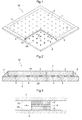
Fig. 1 ] is a partially cutaway perspective view showing an outer appearance of an example of a glass panel relating to the present invention, - [
Fig. 2 ] is a vertical section view of principal portions of the one example of the glass panel relating to the present invention, - [
Fig. 3 ] is an enlarged vertical section view of a gap retention member relating to the present invention, - [
Fig. 4 ] is a function explanatory diagram of the gap retention member relating to the present invention, - [
Fig. 5 ] is a diagram illustrating a determination method of an example, and [Fig. 6 ] is a table showing determination results of the example. - Next, embodiments of the present invention will be explained with reference to the accompanying drawings.
- As shown in
Fig. 1 , in aglass panel 10, betweenopposing faces glass plates gap 4 between oneopposing face 1A and the otheropposing face 2A. Thegap 4 is maintained air-tight along the circumferential portions of the pair ofglass plates opposing faces glass plates material 5 such as a low-melting point glass, a metal material containing lead, tin, indium, etc. is disposed in a fused state, thus providing air-tight seal between the pair ofglass plates gap 4 is maintained under a depressurized state. The plurality ofspacers 3, each one of which can be formed e.g. cylindrical, are disposed between theglass plates - The
glass panel 10 is assembled as described below. As shown inFig. 1 , the plurality ofspacers 3 are disposed between theopposing faces glass plates gap 4 between theglass plates glass plates glass plates material 5 made of a low-melting point glass for sealing the circumferences thereof. Thereafter, gas present in thegap 4 is suctioned through a suction vent provided in one of the pair ofglass plates Fig. 2 ). - The
spacer 3, as shown inFig. 3 , is comprised of two layers ofhard portions 6 which come into contact with theopposing faces glass plates hard portions 6. - The
hard portions 6 are formed of a material that has compression resistance capable of withstanding pressures applied from plate faces of theglass plates glass panel 10 has been manufactured. Specifically, a hard metal material or ceramic material is preferred. More specifically, metal materials such as iron, tungsten, nickel, chrome, titanium, molybdenum, carbon steel, chrome steel, nickel steel, stainless steel, nickel chromium steel, manganese steel, chrome manganese steel, chrome molybdenum steel, silicon steel, nichrome, duralumin, etc., ceramic materials such as corundum, alumina, mullite, magnesia, yttria, aluminum nitride, silicon nitride, etc. can be cited as examples. - The soft portion 7 is provided between the upper and lower
hard portions 6. Specifically, this portion is formed of a soft metal material such as aluminum, copper, nickel, iron, chromium, tin, lead, platinum, indium, zinc, copper, silver, gold or alloys thereof. The soft portion 7 is formed of using e.g. a rolling material and configured such that its rolling direction is aligned along the surfaces of the glass plates. With this, deformation based on a shearing force in the direction along the opposing faces 1 A, 2A will occur more easily than deformation based on a compression force in the thickness direction perpendicular to the opposing faces 1 A, 2A of theglass plates - With the above-described arrangement, deformation of the
spacer 3 in the thickness direction can be suppressed and as for relative movement along the face direction of theglass plates glass plates 1, 2 (Fig. 4 ). - The
hard portions 6 are formed of e.g. stainless steel. In this regard, as the members or parts coming into contact with the surfaces of theglass plates hard portions 6 can be maintained even after long period of use of theglass plates glass plates glass plates glass plates glass plates glass plates glass plates - On the other hand, if the surface-side members which come into contact with the
glass plates hard portions 6 as provided in the above-described arrangement, such deformation will hardly occur in the surfaces of thehard portions 6 as described above. Therefore, the areas of contact with theglass plates glass plates - The shock absorbing ability of the
spacer 3 can be adjusted if desired through adjustment of the thickness of the soft portion 7 disposed at the center thereof. In this regard, increase of the diameter of thespacer 3 will hardly be feasible since this will impair the visibility of windowpane and this also will result in deterioration in heat insulating performance through increase of "heat-bridge effect" due to thespacer 3. On the other hand, increase of its thickness results only in slight increase in the spacing between the opposing faces 1A, 2A of theglass plates spacer 3 will be made more susceptible to deformation in response to the shearing force along the face direction of theglass plates glass plates - In manufacturing of the
spacer 3, there will be effected a step of disposing thehard portions 6 formed of hard metal on opposing sides of the soft portion 7 formed of soft metal and a step of effecting an etching treatment on the outer circumferences of thehard portions 6 and the soft portion 7. In the etching treatment, in comparison with stainless steel for instance, aluminum material will be etched faster. - The exposed area of the soft portion 7 as being sandwiched between the two
hard portions 6 is small. Thus, when the shape of thespacer 3 is to be adjusted through the etching treatment, the surfaces of thehard portions 6 will be etched with higher priority whereas the soft portion 7 will be etched only from the lateral side thereof. With this, etching of the soft portion 7 can be suppressed so that the shape of thespacer 3 can be trimmed easily. - The
spacer 3 is formed e.g. with thehard portions 6 and the soft portion 7 being in contact with each other under a non-bonded state. Here, the language "non-bonded state" means a simple arrangement such as an arrangement of thehard portions 6 and the soft portion 7 being pressed against each other with an appropriate force. Thus, the language excludes such arrangement as connecting between thehard portions 6 and the soft portion 7 with using an adhesive agent additionally. - Even with the above-described arrangement, a compressive force due to the atmospheric pressure is applied constantly to the
spacer 3 once thisspacer 3 has been mounted to the vacuum multilayer glass. Therefore, the relative position between theglass plates spacer 3 can be maintained appropriately, even under the state of thehard portions 6 and the soft portion 7 being simply in contact with each other. On the other hand, when there occurs a mutual positional displacement between theglass plates hard portions 6 and the soft portion 7 can easily move relative to each other along the face direction. For instance, in case a unit area of theglass plates individual spacer 3 is large so that theindividual spacer 3 is subjected to a large load and a large amount of relative movement occurs in the face direction resulting from warping deformation of theglass plates deformable spacer 3 as configured above will be advantageous. - Alternatively, in forming the
spacer 3, the etching treatment can be effected after thehard portions 6 and the soft portion 7 are joined to each other integrally. As a technique for such integral joining thehard portions 6 and the soft portion 7 each other, adhesion using an adhesive material, a thermal diffusion treatment, etc. can be used for instance. With the integral joining between thehard portions 6 and the soft portion 7 as above, the shape of thespacer 3 can be more stable, so that it becomes possible to cause the soft portion 7 to provide its deformation property with higher precision. Since thehard portions 6 and the soft portion 7 are joined to each other, relative movement will occur less likely between the interfaces thereof when a shearing force along the face direction of theglass plates spacer 3. Namely, the resistance against the shearing force will be increased. Therefore, thespacer 3 having the above-described arrangement can be suitably used in e.g. a vacuum multilayer glass using glass plates having high strength capable of withstanding large bending. - (Other Embodiments)
- Next, some other embodiments will be explained.
- <1> The shape of the
spacer 3 can also be angular column shape, ring shape, linear shape, a chain-like shape, etc. instead of the cylindrical shape. - <2> The
spacer 3 can be worked into predetermined dimensions by other technique than the etching treatment, such as a cutting by laser or the like, a punching by pressing, etc. - Next, some examples of the gap retention member (spacer) relating to the present invention will be shown. It is understood however that the present invention is not limited to these examples.
- As shown in structure schematic images in
Fig. 6 , spacers according to Examples 1-2 and Comparison Examples 1-2 were manufactured. Each of these spacers has a cylindrical shape having a diameter of about 500 µm and a height of about 200 µm. Example 1 is a spacer wherein an aluminum foil having a thickness of 20 µm (corresponding to "soft portion") sandwiched at the center portion of the spacer (material: stainless steel, corresponding to "hard portion"), thus providing an arrangement in the order of stainless steel/aluminum foil/stainless steel in the thickness direction. Example 2 is an integrated spacer including an aluminum foil having a thickness of 20 µm at an intermediate portion of the spacer and integrated therein. - Comparison Example 1 is a unit spacer having no soft portion. Comparison Example 2 is a spacer having aluminum foils at portions opposing to a pair of glass plates respectively. In Example 1 and Comparison Example 2, the aluminum foil(s) and the spacer are not bonded to each other. In Example 2, the aluminum foil and the spacer are integrated (joined) to each other by thermal diffusion treatment.
- As shown in
Fig. 5 , each test sample (Examples 1-2, Comparison Examples 1-2) A was placed on aglass plate 11 for determination and anotherglass plate 12 for determination was placed on the test sample A. Then, a pressure equivalent to the atmospheric pressure was applied thereto by placing aweight 13 on thedetermination glass plate 12. Under this state, thedetermination glass plate 12 was moved in the face direction, during which a static friction coefficient of each test sample A was determined. - Incidentally, the determination glass plates were approximately square-shaped glass plates having a thickness of 3 mm and each side of 10 cm in length and these were prepared by a wiping treatment with ethanol and subsequent firing.
- The results of determinations are shown in
Fig. 6 . As shown, in comparison with the unit spacer of Comparison Example 1 (having only hard portion), the average static friction coefficient values of Examples 1 and 2 were approximately 1/2 to 1/4 thereof, and the average static friction coefficient of Example 1 was about 1/3 of that of Comparison Example 2 and the average static friction coefficient of Example 2 was about same as that of Comparison Example 2. Based on these, it can be seen that the spacers of the present invention (Examples 1 and 2) are capable of reducing frictional resistance relative to a glass plate as much as a spacer having aluminum foils on the opposing sides of a glass plate. Namely, the spacers of the present invention (Examples 1 and 2) are capable of allowing relative movement of the glass plates appropriately, like the spacer of Comparison Example 2. -
- 1,
- 2 glass plate
- 1A, 2A
- opposing face
- 3
- spacer (gap retention member)
- 4
- gap
- 6
- hard portion
- 7
- soft portion
Claims (5)
- A glass panel gap retention member to be disposed between a pair of glass plates when a circumference of a gap formed between the pair of glass plates with their plate faces opposing each other is to be sealed to maintain the gap under a depressurized state, the glass panel gap retention member comprising:hard portions to contact the pair of glass plates respectively; a soft portion disposed between the hard portions and having a lower hardness than the hard portions; andthe soft portion being more susceptible to deformation based on a shearing force effective in a direction along the opposing faces of the glass plates than deformation based on a compressive force effective in a thickness direction perpendicular to the opposing faces of the glass plates.
- The glass panel gap retention member according to claim 1, wherein the hard portions are formed of stainless steel material and the soft portion is formed of aluminum material which is rolled in the direction along the opposing faces.
- The glass panel gap retention member according to claim 1 or 2, wherein the hard portions and the soft portion are in contact with each other under a non-bonded state.
- The glass panel gap retention member according to claim 1 or 2, wherein the hard portions and the soft portion are joined to each other integrally.
- A method of manufacturing a glass panel gap retention member to be disposed between a pair of glass plates when a circumference of a gap formed between the pair of glass plates with their plate faces opposing each other is to be sealed to maintain the gap under a depressurized state, the method comprising:a disposing step of disposing hard portions formed of a hard metal on opposing sides of a soft portion formed of a soft metal; andan etching step of etching the hard portions and the soft portion.
Applications Claiming Priority (2)
| Application Number | Priority Date | Filing Date | Title |
|---|---|---|---|
| JP2013253393A JP6305042B2 (en) | 2013-12-06 | 2013-12-06 | Spacing member for glass panel and manufacturing method thereof |
| PCT/JP2014/082074 WO2015083770A1 (en) | 2013-12-06 | 2014-12-04 | Gap retention member for glass panel and method for manufacturing same |
Publications (2)
| Publication Number | Publication Date |
|---|---|
| EP3078645A1 true EP3078645A1 (en) | 2016-10-12 |
| EP3078645A4 EP3078645A4 (en) | 2017-04-19 |
Family
ID=53273530
Family Applications (1)
| Application Number | Title | Priority Date | Filing Date |
|---|---|---|---|
| EP14867715.6A Withdrawn EP3078645A4 (en) | 2013-12-06 | 2014-12-04 | Gap retention member for glass panel and method for manufacturing same |
Country Status (6)
| Country | Link |
|---|---|
| US (1) | US9890578B2 (en) |
| EP (1) | EP3078645A4 (en) |
| JP (1) | JP6305042B2 (en) |
| KR (1) | KR20160093705A (en) |
| CN (1) | CN105873875B (en) |
| WO (1) | WO2015083770A1 (en) |
Cited By (1)
| Publication number | Priority date | Publication date | Assignee | Title |
|---|---|---|---|---|
| WO2021059167A1 (en) * | 2019-09-23 | 2021-04-01 | Guardian Glass, LLC | Low thermal conductivity metal-polymer-metal sandwich composite spacer system for vacuum insulated glass (vig) units, vig units including composite spacers, and methods of making the same |
Families Citing this family (5)
| Publication number | Priority date | Publication date | Assignee | Title |
|---|---|---|---|---|
| EP3383814B1 (en) * | 2015-11-30 | 2022-08-10 | Corning Incorporated | Laser welding transparent glass panes using a low emissivity coating |
| JP6767702B2 (en) * | 2016-08-31 | 2020-10-14 | パナソニックIpマネジメント株式会社 | Glass panel unit and glass window |
| JP7716852B2 (en) * | 2018-09-05 | 2025-08-01 | 日本板硝子株式会社 | Vacuum glass and its manufacturing method |
| CN109675925A (en) * | 2019-01-11 | 2019-04-26 | 北京北冶功能材料有限公司 | A kind of vacuum glass support 3-layer composite material and preparation method thereof |
| WO2021009356A1 (en) | 2019-07-17 | 2021-01-21 | Central Glass Co., Ltd. | Multi-part glazing |
Family Cites Families (9)
| Publication number | Priority date | Publication date | Assignee | Title |
|---|---|---|---|---|
| US3350772A (en) * | 1962-08-15 | 1967-11-07 | Composite Metal Products Inc | Methods of cladding stainless steel to aluminum |
| US4103076A (en) * | 1973-12-10 | 1978-07-25 | Clad Metals, Inc. | Clad metal product of Cu, Al and stainless steel |
| AUPM888994A0 (en) * | 1994-10-19 | 1994-11-10 | University Of Sydney, The | Design improvement to vacuum glazing |
| JPH11349358A (en) * | 1998-06-08 | 1999-12-21 | Nippon Sheet Glass Co Ltd | Interval-retaining part for glass panel |
| CN1274339A (en) * | 1998-06-08 | 2000-11-22 | 日本板硝子株式会社 | Spacer for glass panel |
| AUPQ349499A0 (en) * | 1999-10-18 | 1999-11-11 | University Of Sydney, The | Method of producing support pillars |
| JP4567894B2 (en) * | 2001-01-29 | 2010-10-20 | 日本板硝子株式会社 | Glass panel |
| JP4171626B2 (en) * | 2002-09-03 | 2008-10-22 | 富士通株式会社 | Liquid crystal display |
| US7179512B2 (en) | 2002-05-14 | 2007-02-20 | Fujitsu Limited | Liquid crystal display and manufacturing method of same |
-
2013
- 2013-12-06 JP JP2013253393A patent/JP6305042B2/en active Active
-
2014
- 2014-12-04 EP EP14867715.6A patent/EP3078645A4/en not_active Withdrawn
- 2014-12-04 WO PCT/JP2014/082074 patent/WO2015083770A1/en not_active Ceased
- 2014-12-04 KR KR1020167017873A patent/KR20160093705A/en not_active Abandoned
- 2014-12-04 US US15/100,467 patent/US9890578B2/en not_active Expired - Fee Related
- 2014-12-04 CN CN201480066384.5A patent/CN105873875B/en not_active Expired - Fee Related
Cited By (1)
| Publication number | Priority date | Publication date | Assignee | Title |
|---|---|---|---|---|
| WO2021059167A1 (en) * | 2019-09-23 | 2021-04-01 | Guardian Glass, LLC | Low thermal conductivity metal-polymer-metal sandwich composite spacer system for vacuum insulated glass (vig) units, vig units including composite spacers, and methods of making the same |
Also Published As
| Publication number | Publication date |
|---|---|
| JP2015110494A (en) | 2015-06-18 |
| JP6305042B2 (en) | 2018-04-04 |
| KR20160093705A (en) | 2016-08-08 |
| CN105873875B (en) | 2018-11-23 |
| EP3078645A4 (en) | 2017-04-19 |
| WO2015083770A1 (en) | 2015-06-11 |
| CN105873875A (en) | 2016-08-17 |
| US9890578B2 (en) | 2018-02-13 |
| US20160298377A1 (en) | 2016-10-13 |
Similar Documents
| Publication | Publication Date | Title |
|---|---|---|
| US9890578B2 (en) | Glass panel gap retention member and method for manufacturing same | |
| US20120269996A1 (en) | Heat insulating glazing element and methods for its manufacture | |
| TW300271B (en) | ||
| EP1506945B1 (en) | Translucent glass panel | |
| US8329267B2 (en) | Flexible edge seal for vacuum insulating glazing units | |
| CN1277778C (en) | Method for producing glass panel and glass panel produced by the method | |
| US20140205774A1 (en) | Glazing unit with peripheral seal and corresponding manufacturing process | |
| JP2016044097A (en) | Gap holding member | |
| US11162298B2 (en) | Compressible pillar for a vacuum insulated glazing unit | |
| JPH08230098A (en) | Metal sandwich structure and method for manufacturing the same | |
| CN110204222B (en) | Differential elasticity modulus support column array and vacuum glass | |
| EP2543938A1 (en) | Method for manufacturing a vacuum solar thermal panel and related vacuum solar thermal panel | |
| JP5980110B2 (en) | Diffusion bonding jig and diffusion bonding method | |
| JP2014162701A (en) | Double glazing, and production method thereof | |
| JP2019060085A (en) | Glass panel and fitting | |
| EP3604727B1 (en) | Glass panel unit and glass window | |
| JP2014080313A (en) | Double glass, and manufacturing method of double glass | |
| AU686461B2 (en) | Design improvements to vacuum glazing | |
| JP2007238351A (en) | Spacer material for double glass | |
| JPH11199279A (en) | Vacuum insulated glass | |
| CA2448923C (en) | Design improvements to vacuum glazing | |
| JP2015202992A (en) | Vacuum double-glazed glass | |
| JP2014041922A (en) | Solar battery module |
Legal Events
| Date | Code | Title | Description |
|---|---|---|---|
| PUAI | Public reference made under article 153(3) epc to a published international application that has entered the european phase |
Free format text: ORIGINAL CODE: 0009012 |
|
| 17P | Request for examination filed |
Effective date: 20160523 |
|
| AK | Designated contracting states |
Kind code of ref document: A1 Designated state(s): AL AT BE BG CH CY CZ DE DK EE ES FI FR GB GR HR HU IE IS IT LI LT LU LV MC MK MT NL NO PL PT RO RS SE SI SK SM TR |
|
| AX | Request for extension of the european patent |
Extension state: BA ME |
|
| DAX | Request for extension of the european patent (deleted) | ||
| A4 | Supplementary search report drawn up and despatched |
Effective date: 20170320 |
|
| RIC1 | Information provided on ipc code assigned before grant |
Ipc: E06B 3/673 20060101ALI20170314BHEP Ipc: E06B 3/663 20060101ALI20170314BHEP Ipc: C03C 27/06 20060101AFI20170314BHEP Ipc: E06B 3/66 20060101ALI20170314BHEP Ipc: E06B 3/677 20060101ALI20170314BHEP |
|
| STAA | Information on the status of an ep patent application or granted ep patent |
Free format text: STATUS: EXAMINATION IS IN PROGRESS |
|
| 17Q | First examination report despatched |
Effective date: 20210430 |
|
| GRAP | Despatch of communication of intention to grant a patent |
Free format text: ORIGINAL CODE: EPIDOSNIGR1 |
|
| STAA | Information on the status of an ep patent application or granted ep patent |
Free format text: STATUS: GRANT OF PATENT IS INTENDED |
|
| INTG | Intention to grant announced |
Effective date: 20211018 |
|
| RAP3 | Party data changed (applicant data changed or rights of an application transferred) |
Owner name: THE UNIVERSITY OF SYDNEY Owner name: NIPPON SHEET GLASS COMPANY, LIMITED |
|
| RIN1 | Information on inventor provided before grant (corrected) |
Inventor name: KOCER, CENK Inventor name: ASANO, OSAMU Inventor name: KAWASHIMA, YUMI |
|
| STAA | Information on the status of an ep patent application or granted ep patent |
Free format text: STATUS: THE APPLICATION IS DEEMED TO BE WITHDRAWN |
|
| 18D | Application deemed to be withdrawn |
Effective date: 20220301 |