EP3078638B1 - Water filter cartridge and water tank - Google Patents
Water filter cartridge and water tank Download PDFInfo
- Publication number
- EP3078638B1 EP3078638B1 EP16159547.5A EP16159547A EP3078638B1 EP 3078638 B1 EP3078638 B1 EP 3078638B1 EP 16159547 A EP16159547 A EP 16159547A EP 3078638 B1 EP3078638 B1 EP 3078638B1
- Authority
- EP
- European Patent Office
- Prior art keywords
- water
- magnetic field
- tank
- filter cartridge
- filter
- Prior art date
- Legal status (The legal status is an assumption and is not a legal conclusion. Google has not performed a legal analysis and makes no representation as to the accuracy of the status listed.)
- Active
Links
- XLYOFNOQVPJJNP-UHFFFAOYSA-N water Substances O XLYOFNOQVPJJNP-UHFFFAOYSA-N 0.000 title claims description 156
- 238000004891 communication Methods 0.000 claims description 73
- 230000000295 complement effect Effects 0.000 claims description 12
- 235000013361 beverage Nutrition 0.000 claims description 4
- 238000000576 coating method Methods 0.000 claims description 4
- 238000003860 storage Methods 0.000 claims description 4
- 239000011248 coating agent Substances 0.000 claims description 3
- 239000003651 drinking water Substances 0.000 claims 1
- 235000020188 drinking water Nutrition 0.000 claims 1
- 230000000694 effects Effects 0.000 description 13
- 230000008901 benefit Effects 0.000 description 6
- 230000005540 biological transmission Effects 0.000 description 6
- 238000013461 design Methods 0.000 description 6
- 230000006872 improvement Effects 0.000 description 5
- 230000005855 radiation Effects 0.000 description 5
- 235000015114 espresso Nutrition 0.000 description 3
- 230000003321 amplification Effects 0.000 description 2
- 235000013353 coffee beverage Nutrition 0.000 description 2
- 239000013505 freshwater Substances 0.000 description 2
- 238000004519 manufacturing process Methods 0.000 description 2
- 238000003199 nucleic acid amplification method Methods 0.000 description 2
- 230000035699 permeability Effects 0.000 description 2
- 230000009467 reduction Effects 0.000 description 2
- 238000000926 separation method Methods 0.000 description 2
- 230000002411 adverse Effects 0.000 description 1
- 230000004323 axial length Effects 0.000 description 1
- 230000007748 combinatorial effect Effects 0.000 description 1
- 238000011161 development Methods 0.000 description 1
- 230000018109 developmental process Effects 0.000 description 1
- 238000009826 distribution Methods 0.000 description 1
- 239000000706 filtrate Substances 0.000 description 1
- 238000003780 insertion Methods 0.000 description 1
- 230000037431 insertion Effects 0.000 description 1
- 239000007788 liquid Substances 0.000 description 1
- 239000000696 magnetic material Substances 0.000 description 1
- 238000000034 method Methods 0.000 description 1
- 230000004048 modification Effects 0.000 description 1
- 238000012986 modification Methods 0.000 description 1
- 238000002360 preparation method Methods 0.000 description 1
- 230000008569 process Effects 0.000 description 1
- 230000000717 retained effect Effects 0.000 description 1
- 238000007789 sealing Methods 0.000 description 1
- 238000004804 winding Methods 0.000 description 1
Images


Classifications
-
- C—CHEMISTRY; METALLURGY
- C02—TREATMENT OF WATER, WASTE WATER, SEWAGE, OR SLUDGE
- C02F—TREATMENT OF WATER, WASTE WATER, SEWAGE, OR SLUDGE
- C02F1/00—Treatment of water, waste water, or sewage
- C02F1/001—Processes for the treatment of water whereby the filtration technique is of importance
- C02F1/003—Processes for the treatment of water whereby the filtration technique is of importance using household-type filters for producing potable water, e.g. pitchers, bottles, faucet mounted devices
-
- C—CHEMISTRY; METALLURGY
- C02—TREATMENT OF WATER, WASTE WATER, SEWAGE, OR SLUDGE
- C02F—TREATMENT OF WATER, WASTE WATER, SEWAGE, OR SLUDGE
- C02F2201/00—Apparatus for treatment of water, waste water or sewage
- C02F2201/002—Construction details of the apparatus
- C02F2201/006—Cartridges
-
- C—CHEMISTRY; METALLURGY
- C02—TREATMENT OF WATER, WASTE WATER, SEWAGE, OR SLUDGE
- C02F—TREATMENT OF WATER, WASTE WATER, SEWAGE, OR SLUDGE
- C02F2209/00—Controlling or monitoring parameters in water treatment
- C02F2209/005—Processes using a programmable logic controller [PLC]
- C02F2209/008—Processes using a programmable logic controller [PLC] comprising telecommunication features, e.g. modems or antennas
-
- C—CHEMISTRY; METALLURGY
- C02—TREATMENT OF WATER, WASTE WATER, SEWAGE, OR SLUDGE
- C02F—TREATMENT OF WATER, WASTE WATER, SEWAGE, OR SLUDGE
- C02F2209/00—Controlling or monitoring parameters in water treatment
- C02F2209/44—Time
- C02F2209/445—Filter life
-
- C—CHEMISTRY; METALLURGY
- C02—TREATMENT OF WATER, WASTE WATER, SEWAGE, OR SLUDGE
- C02F—TREATMENT OF WATER, WASTE WATER, SEWAGE, OR SLUDGE
- C02F2307/00—Location of water treatment or water treatment device
- C02F2307/04—Location of water treatment or water treatment device as part of a pitcher or jug
Definitions
- the invention relates to a water filter cartridge, a water tank and a water-conducting device according to the preambles of claims 1, 9 and 13.
- water filter cartridges are increasingly being used to treat the water before it is actually used.
- Such filter cartridges are designed to be inserted into the water tank and for this purpose are provided with a connection element for connecting a filter drain line to a tank-side connection element.
- the filter housing is provided with permanently open inlet openings for the entry of water from the environment, i.e. from the water tank, so that the water tank can be emptied via the filter cartridge. The water is sucked out via the filter cartridge by a suction pump on the household appliance.
- the state of the art already recognizes that a frequency detuning can occur when electromagnetic waves are transmitted through water. Therefore, in this case, the state of the art provides for a targeted detuning between the communication element on the filter cartridge side and the external communication element arranged on the side of the household appliance during manufacture or when setting the transmission and/or reception frequencies in order to compensate for such a frequency detuning.
- the EN 10 2014 117 725 A1 , EN 10 2006 029 105 A1 and the EN 10 2014 117 720 A1 disclose a beverage machine and a water storage tank that can be connected thereto or a water filter cartridge for insertion into such a water storage tank, each of which communicates with antennas by means of electronic communication elements.
- the object of the present invention is to improve the communication between such electronic communication elements.
- a water filter cartridge for use in a water storage tank of a water-conducting device comprises a filter housing, a filter-side tank connection element and an electronic communication element with antenna as well as at least one magnetic field conducting element.
- such a magnetic field guide element can have magnetic Materials with a permeability number that is significantly greater than 1 ( ⁇ r » 1).
- ⁇ r » 1 a magnetic field conducting element designed in this way.
- the significantly higher conductivity in the magnetic field conducting element compared to its surroundings, such as air and/or plastic, from which filter housings and their mechanical components are usually made, causes a concentration or bundling of magnetic field lines in the interior and/or in the vicinity of such a magnetic field conducting element.
- the magnetic field guide element By arranging and/or aligning a magnetic field guide element in relation to an antenna of an electronic communication element, a significant portion of an occurring magnetic field can be directed in its direction in a targeted manner. It is particularly advantageous if the magnetic field guide element is arranged in an area between two antennas, e.g. between an antenna of a transmitting electronic communication element and an antenna of an electronic communication element operated in receive mode. In one possible embodiment, the magnetic field guide element can therefore be arranged in an area of the water filter cartridge that is located between the antenna of the filter-side electronic communication element and a point on the water filter cartridge, which point, when the water filter cartridge is inserted, points in the direction of the antenna of a complementary tank-side communication element and/or device-side communication element provided for communication with the filter-side communication element.
- the concentration or bundling of the magnetic field also results in local amplification effects for the magnetic field.
- the amplification effect of the magnetic field guide element based on the field line concentration This can advantageously result in a massive increase in level and thus significantly improved data transmission between the two electronic communication elements.
- a much higher reception signal can be fed to the receiving antenna.
- disruptive magnetic radiation to the outside is reduced to a corresponding extent. External interference can in turn be filtered out much better due to the much higher internal system level.
- the same reception level strength can be achieved by means of a magnetic field guide element with a significantly reduced transmission power due to the field concentration in the preferred transmission direction between the antennas involved.
- the shape of such a magnetic field guide element can be, for example, ring-shaped, pin-shaped, thread-shaped or the like. In the latter cases, it is advantageous if several such elements are arranged, e.g., viewed in cross section, at least partially distributed in a ring-like manner.
- a type of cage can be formed by such a ring-shaped and/or arranged structure of one or more magnetic field guide elements. The advantage of such a cage lies in a ring-shaped distribution, locally greatly improved guidance or concentration of magnetic field lines, viewed in cross section, along a cage formed in this way.
- Such a cage can be formed, for example, from several pins, threads or the like and/or combinations of such elongated structures.
- a sleeve-shaped, i.e. ring-shaped embodiment with a certain axial length is considered particularly preferred. This allows the field pattern to be influenced as evenly as possible in relation to an embodiment viewed in cross section. This is all the better the more closed the casing of the sleeve is.
- a variation in the sleeve shape can be made possible by means of an interruption formed in the magnetic field conducting element structure.
- attachment to the water filter cartridge can be made easier by stretching and/or compressing.
- radial and/or axial deformation can be supported and/or enabled by means of one or more slots in the magnetic field conducting element structure. Possible slot shapes can be formed axially and/or transversely to the longitudinal extension and/or in combination, e.g. in relation to the longitudinal axis of the magnetic field conducting element.
- the magnetic field conducting element and/or several magnetic field conducting elements By overlapping the casing sections of the magnetic field conducting element and/or several magnetic field conducting elements, its or their magnetic field conducting properties can continue to enable a closed effect even if the circumference and/or the longitudinal extent of the magnetic field conducting element changes. For example, by widening, compressing and/or telescoping, a maximum magnetic field conducting effect can be provided even if the arrangement of the magnetic field conducting element on the water filter cartridge is made easier.
- a magnetic field guide element can be attached and/or applied, for example in the form of a coating in and/or on the water filter cartridge.
- a separating layer can be provided so that no contact-related negative effects can be caused on the water being treated and/or treated by the water filter cartridge.
- a magnetic field conducting element can, for example, be overmolded.
- the magnetic field conducting element and/or the separating layer can, for example, be incorporated as an integral part in the filter housing, i.e. the housing of the filter cartridge. It is particularly advantageous in terms of avoiding contact with water if the magnetic field conducting element is completely encased.
- the magnetic field conducting element is already provided with a separating layer before it is inserted into the water filter cartridge, this increases the potential arrangement options for the magnetic field conducting element in and/or on the water filter cartridge.
- it can then also be arranged as a separately manufactured part in and/or on the water filter cartridge or connected to it. It can also be exchangeable, e.g. in the form of a replacement element.
- the magnetic field conducting element can be arranged in the area of the filter-side tank connection element.
- the term "area” is also understood to mean an arrangement that is located, for example, behind a wall of the filter and/or the tank and/or the water-carrying device. It is important that the magnetic field conducting or concentrating Property can be used advantageously to improve communication between antennas.
- an arrangement of the magnetic field conducting element may be appropriate, in particular, radially inside or outside of one or the other antenna.
- a magnetic field guide element arranged radially inside at least the antenna of the electronic communication element arranged on the water filter cartridge can, for example, be designed such that it preferably also reaches very close to the antenna of the complementary electronic communication element on a tank-side filter connection element. And/or also to an antenna that is arranged in and/or on a device in which such a water tank is to be inserted for its operation.
- a magnetic field guide element arranged outside the antenna of the electronic communication element arranged on the filter side can offer the advantage of even better shielding against magnetic radiation to the outside. It can therefore be particularly advantageous to provide a magnetic field guide element both inside and outside the antenna of the electronic communication element arranged on the water filter with a combinatorial effect both with regard to concentration and shielding function.
- the magnetic field conducting element can be arranged in the region of a water outlet opening of the water filter cartridge.
- the water outlet opening is formed in the region of the filter-side tank connection element.
- the filter-side tank connection element can also cause a separation between the raw or fresh water to be kept in a water tank and treated by the water filter cartridge and the water treated by the water filter cartridge.
- the inlet into the water filter cartridge can be realized by at least one water inlet opening provided on the filter housing. This is preferably arranged relatively low in relation to the water level when the filter cartridge is inserted, e.g. approximately at the level of a water outlet opening from the water filter cartridge, so that as far as possible the entire tank contents can be emptied through the water filter cartridge.
- a water tank which comprises a tank housing, a tank outlet opening and a tank-side filter connection element, wherein a magnetic field conducting element is provided.
- a magnetic field conducting element is provided.
- an electronic communication element with an antenna can also be provided.
- This magnetic field conducting element also serves to improve communication between two complementary electronic communication elements.
- These communication elements can be provided on the one hand on a water tank and on the other hand on a water filter cartridge intended for connection to such a water tank.
- the complementary electronic communication element can also be provided on a water-conducting device to which the water tank in question is to be connected, in particular for operating such a device, e.g. a drinks machine. This allows the water-conducting device to communicate either directly with the water filter cartridge and/or possibly also via the tank.
- a drinks machine can be, for example, an espresso machine, a fully automatic coffee machine or the like.
- the magnetic field conducting element can be arranged in and/or on the tank-side filter connection element and/or on a tank-side device connection element.
- the magnetic field conducting element described above with regard to the water filter cartridge by arranging it as close as possible to a relevant antenna for an electronic communication element, an optimal concentration for the magnetic field interacting with this antenna and thus a massive improvement in data communication with a corresponding electronic communication element on a water filter cartridge and/or on a device to which the water tank can be connected can be achieved.
- tank-side magnetic field conducting element in relation to a filter-side magnetic field conducting element, or vice versa, at the smallest possible distance from one another.
- the tank-side and filter-side magnetic field conducting elements can be aligned with one another when the water filter cartridge is inserted so that their front sides are positioned close to one another, in particular positioned opposite one another.
- the tank-side and filter-side magnetic field conducting elements can be arranged axially superimposed, thus further improving the radial magnetic field conducting effect.
- the arrangement of a magnetic field guide element can be arranged in the area of a water outlet opening of the water tank.
- This water outlet opening of the water tank is particularly preferably designed for connection to a water-carrying device, such as a beverage preparation machine.
- the magnetic field conducting element can be used to improve communication between a communication element with antenna arranged on the tank and/or on a water filter cartridge inserted therein and an electronic communication means with antenna arranged on the water-carrying device.
- a water-conducting device e.g. a drinks machine, with a machine-side tank connection element for connection to a water tank, in particular to a tank-side device connection element, and with an electronic communication means with antenna, wherein a magnetic field conducting element is provided.
- a magnetic field conducting element is provided.
- the magnetic field guide element is arranged in the area of the device-side tank connection element, since this allows the magnetic field lines to be guided as narrowly or closed as possible. This also applies to all embodiments.
- a magnetic field guide element for a water filter cartridge and/or a water tank and/or a water-conducting device, in particular a drinks machine is proposed, wherein the magnetic field conducting element comprises a connection provided for connection to a water filter cartridge and/or a water tank and/or a water-conducting device, in particular a drinks machine.
- this connection can be designed as a plug-in connection.
- the magnetic field conducting element can thus be designed, for example, in the form of a retrofit element.
- Such an element can, for example, contribute to improving communication between two complementary communication elements with antennas. This can also be retrofitted, particularly advantageously, for combinations that are on the market and/or in operation.
- a further advantage is that the magnetic field conducting element can be designed as a removable element. This is particularly advantageous for an arrangement on a water filter cartridge. When such a cartridge is used up, an exchangeable magnetic field conducting element can be removed from this used water filter cartridge and inserted into a new water filter cartridge and reused in a material- and cost-saving and environmentally friendly manner.
- connection can be designed as a sliding and/or plug-in connection, in particular as a push-in and/or slide-on and/or plug-on and/or clamp connection.
- this slide-on and/or plug-on and/or clamp connection version can also represent EMC protection for the relevant communication path by reducing magnetic radiation escaping to the outside.
- this embodiment can also be combined with the plug-in connection design described above.
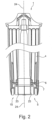
- FIG. 1 the schematic sectional view according to Figure 1 detail of a water filter cartridge 1, a water tank 2 and, more generally, a water-conducting and/or water-treating device 3, which can in particular be a drinks machine, such as an espresso machine, a fully automatic coffee machine or the like.
- a drinks machine such as an espresso machine, a fully automatic coffee machine or the like.
- water tanks 2 are usually arranged on the machine side to hold fresh or raw water.
- water filter cartridges To protect the device in question, in particular its water-carrying and water-treating components, and to improve the taste of the drinks prepared or treated by the device in question, the use of water filter cartridges is regularly provided.
- the water to be supplied to the water-carrying device is usually taken from the water tank 2 in a flow-through process, introduced into the water filter cartridge via a water inlet opening 10 formed as low as possible on the filter cartridge 1 with respect to the minimum liquid level, guided over a filter section arranged therein, for example a filter bed 12, for the treatment of the raw or fresh water and led out of this via a water outlet opening 11, which is also usually as low as possible.
- a water outlet opening 11 can be particularly advantageously formed within a filter-side tank connection element 5 of the water filter cartridge 1.
- a filter-side tank connection element 5, when connected to a tank-side filter connection element 8, can thus create a separation between the fresh or raw water area inside the water tank 2 and the filtrate area, i.e. the area in which the water treated by the water filter cartridge is fed out of the cartridge and to the water-carrying or water-treating device.
- FIG. 1 a partial sectional view of a water filter cartridge 1, comprising a filter housing 4, a filter-side tank connection element 5, an electronic communication element 6 with antenna 7.
- a complementary electronic communication element such as shown with 19, a Data exchange, i.e. electronic communication, can be carried out.
- the device can check whether a correct filter cartridge 1 intended for the relevant operation is inserted.
- the water flow which is indicated by the dashed line 9 as an example, enters the filter cartridge through a water inlet opening 10 formed on the filter housing 4 near the filter-side tank connection element 5, flows over a filter bed 12 and exits the water filter cartridge 1 again at a preferably central, bottom-side water outlet opening 11.
- the water treated by the water filter cartridge 1 flows as a water stream 9 through a tank outlet opening 13 formed in the tank bottom 14 within the tank-side filter connection element 8 and connecting this to a tank-side device connection element 15 in a fluid-conducting manner into a device-side tank connection element 16 and further via a line 17 to the water-conducting or water-treating device 3.
- windings of an antenna 18 of an electronic communication element 19, which in this case is also arranged on the water-conducting device 3 as an example, are shown schematically, which are connected to one another via a symbolic line 20.
- a seal 21 is arranged on the device-side tank connection element in such a way that a tank-side device connection nozzle 22 arranged on the outside of the tank bottom seals the flow guide thus formed for the water flow 9 to the outside by connecting the tank-side device connection element 15 to the device-side tank connection element 16.
- Those parts of the field lines that do not, or at least do not substantially, participate in the transmission between the two antennas can cause interference to the outside and do not contribute to the communication, at least not significantly.
- the Figure 2 shows, by way of example, a water filter cartridge 1 with a filter housing 4, water inlet opening 10, a filter-side tank connection element 5 and a magnetic field guide element 23 arranged in its area.
- the magnetic field guide element 23 is arranged radially within an antenna 7 of an electronic communication element 6. By axially aligning it with respect to a longitudinal axis 24 of the water filter cartridge, magnetic field lines occurring in this area are bundled around this magnetic field guide element, and in particular in this, to form a significantly increased magnetic field.
- the magnetic field guide element 23 is formed in the area of the antenna 7, towards the connection-side front side of the water filter cartridge or its filter-side tank connection element 5, a targeted magnetic field guidance can thus be achieved, in particular towards an antenna of a complementary communication element, such as the antenna 18 of the device-side electronic communication element 19. This can bring about a significant improvement in the communication between these two antennas or the associated communication elements.
- a further embodiment of a magnetic field guide element 34 is shown on the right half of the illustration of the Figure 3 shown as an example. It has a longitudinal extension, Preferably, this extends in the longitudinal direction from the connection-side front side of the filter cartridge in the direction of the antenna 7 of the communication element 6. This longitudinal extension can also advantageously extend beyond the antenna 7. This can, on the one hand, result in better magnetic field conduction between this antenna 7 and a correspondingly complementary antenna.
- the section of this magnetic field conducting element 35 that lies outside the essentially direct communication path between the antennas offers a shielding effect, both inwards and outwards.
- this magnetic field conducting element 34 is sleeve-shaped.
- a separating layer 35 is provided here again as an example for all possible embodiments.
- the separating layers 35 on the magnetic field conducting elements 25 and 27 are shown as examples of such a separating layer.
- the Figure 3 shows a partial sectional view of a filter-side tank connection element 5 of a water filter cartridge 1.
- an electronic communication element with antenna 7 is shown, which antenna is, for example, ring-shaped and can therefore also be seen in its sectional view in the left half of the image.
- the magnetic field guide element 25 is, as the embodiment in the Figure 2 , arranged radially inside the antenna 7 and extending axially in the water filter cartridge. This can therefore also be used to create a magnetic field line concentration within the water filter cartridge 1 and its surroundings.
- This magnetic field conducting element 25 can, for example, interact with a further magnetic field conducting element 26, which is also designed to extend axially in the longitudinal direction and which, in this example, is arranged radially further out in the water filter housing 4 than the magnetic field conducting element 25.
- the reason for this can, for example, be a radial expansion of the structures in the connection area.
- these two magnetic field conducting elements can, for example, each represent two sleeve-shaped embodiments, which can be arranged at the relevant positions within the filter cartridge. For example, by plugging them onto an element for the outlet of the water treated by the water filter cartridge.
- a further embodiment is shown on the left half of the image by the magnetic field guide element 27, which extends from the antenna to the front end of the filter-side tank connection element.
- This embodiment has the advantage that a continuous magnetic field line line is possible in this area. This can be implemented, for example, by coating a corresponding inner area of the water filter cartridge, or by a correspondingly shaped sleeve.
- a further possible embodiment is shown by the magnetic field guide element 28, which is arranged radially outside the antenna 7 in and/or on a region of the filter cartridge housing 4.
- This can, on the one hand, provide a shielding of magnetic field lines occurring inside the filter cartridge from the outside, and, on the other hand, a shielding possibly from the outside magnetic field lines, which could otherwise interfere with the communication of the antennas.
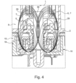
- FIG. 4 shows a tank 2 with a filter connection element 8 on the tank side and a water filter cartridge 1 connected to it with its filter-side tank connection element 5 and a tank-side device connection element 15 and a device-side tank connection element 16 connected to it.
- a magnetic field conducting element 30 is shown in the central area of the water filter cartridges, water tank and the respective connection elements 5, 8 and 15, 16.
- magnetic field lines 29 are drawn in, which run between the two antennas 7 and 18.
- the magnetic field conducting element 30 causes a concentration of the magnetic field lines in its interior. This means that the magnetic field in this area can be significantly concentrated or strengthened. In addition, this effect can reduce disruptive influences from outside. Disturbances, such as those caused by water-related imbalances, can also be significantly reduced in their effect.
- This magnetic field conducting element can, for example, be arranged in the area of the water discharge from the tank, e.g. inserted into the tank outlet opening 13.
- a sealing means can be arranged between the magnetic field conducting element 30 and the tank outlet opening 13.
- Such an embodiment can be realized, for example, as a plug-in connection.
- the magnetic field conducting element itself is preferably designed in the form of a sleeve, so that on the one hand an optimal magnetic field conduction can take place in the wall of the sleeve and on the other hand a A fluid-carrying connection can be made between the tank outlet and the device-side water connection.
- a valve can also be provided in the tank outlet opening, which closes the tank if the device-side tank connection is not connected to a device-side tank connection. This also applies to all possible versions of the water tanks described here.
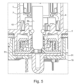
- the Figure 5 shows the same structure as the Figure 4 .
- a further magnetic field conducting element 31 is shown here, essentially in the form of a disk or a ring. It is arranged on the side outside the device connection-side antenna 18 with respect to the magnetic field formed by its magnetic field lines 29. This means that it can capture field lines radiating in this direction and, via a possible contact point with the magnetic field conducting element 30, introduce the magnetic field thus formed into the latter, further amplifying it.
- a further effect here is additional shielding both inwards and outwards.
- the magnetic field conducting element 31 can be provided both in addition to the magnetic field conducting element 30 and, in a possible alternative embodiment, without it.
- the Figure 6 shows a modification of the one in the Figure 5 shown version.
- the magnetic field guide element 31 shown here has been modified to form a pot-shaped magnetic field guide element 32.
- This encloses with its outer sleeve-shaped wall the tank-side filter connection element 8 and the antenna 18 arranged therein for the device-side electronic communication element (cf. Figure 1 ). Due to this pot-shaped design of the magnetic field guide element 32, the entire interior of the device-side tank connection element 16 can be magnetically This can result in a further improvement in the communication between the two antennas 18 and 7. The same also applies to the improvement in the reduction of electromagnetic interference.
- a further magnetic field guide element 33 is arranged in the tank 2, for example. It is preferably aligned with the wall of the pot-shaped magnetic field guide element 32 in the device-side tank connection element 16 and also preferably extends to near the height at which the antenna 7 of the filter-side electronic communication element 6 is positioned when plugged into the tank.
- the magnetic field guide element 33 also preferably extends a little further in the axial direction beyond it, so that on the one hand the escape of magnetic field lines into this area can at least be contained and on the other hand a shield against magnetic interference from the outside can also be achieved.
Landscapes
- Life Sciences & Earth Sciences (AREA)
- Hydrology & Water Resources (AREA)
- Engineering & Computer Science (AREA)
- Environmental & Geological Engineering (AREA)
- Water Supply & Treatment (AREA)
- Chemical & Material Sciences (AREA)
- Organic Chemistry (AREA)
- Water Treatment By Electricity Or Magnetism (AREA)
- Separation Using Semi-Permeable Membranes (AREA)
Description
Die Erfindung betrifft eine Wasserfilterpatrone, einen Wassertank und ein wasserführendes Gerät nach den Oberbegriffen der Ansprüche 1, 9 und 13. In Haushaltsgeräten mit Wassertank, beispielsweise Getränkemaschinen, wie Espressomaschinen oder dergleichen, werden vermehrt Wasserfilterpatronen eingesetzt, um das Wasser vor der eigentlichen Verwendung aufzubereiten. Derartige Filterpatronen sind zum Einsetzen in den Wassertank ausgebildet und zu diesem Zweck mit einem Anschlusselement zum Anschluss einer Filterablaufleitung an ein tankseitiges Anschlusselement versehen. Das Filtergehäuse wird mit permanent offenen Eintrittsöffnungen für den Eintritt von Wasser aus der Umgebung, das heißt aus dem Wassertank versehen, sodass der Wassertank über die Filterpatrone entleerbar ist. Das Wasser wird dabei über eine Saugpumpe des Haushaltsgeräts über die Filterpatrone abgesaugt.The invention relates to a water filter cartridge, a water tank and a water-conducting device according to the preambles of
Zur Vermeidung des Einsatzes eines ungeeigneten Filtertyps oder auch zur Erkennung einer erschöpften Filterpatrone wurde bei einer solchen Filterpatrone zusätzlich der Einsatz eines elektronischen Kommunikationselementes bekannt. Eine solche Filterpatrone wird in der Druckschrift
Bei diesem Stand der Technik wird bereits erkannt, dass bei der Transmission elektromagnetischer Wellen durch Wasser eine Frequenzverstimmung eintreten kann. Deshalb wird beim Stand der Technik für diesen Fall bei der Fertigung bzw. der Einstellung der Sende- und/oder Empfangsfrequenzen eine gezielte Verstimmung zwischen dem filterpatronenseitigen Kommunikationselement und dem externen Kommunikationselement, das auf Seiten des Haushaltsgerätes angeordnet ist, vorgesehen, um eine solche Frequenzverstimmung zu kompensieren.This state of the art already recognizes that a frequency detuning can occur when electromagnetic waves are transmitted through water. Therefore, in this case, the state of the art provides for a targeted detuning between the communication element on the filter cartridge side and the external communication element arranged on the side of the household appliance during manufacture or when setting the transmission and/or reception frequencies in order to compensate for such a frequency detuning.
Die
Aufgabe der vorliegenden Erfindung ist es, die Kommunikation zwischen solchen elektronischen Kommunikationselementen zu verbessern.The object of the present invention is to improve the communication between such electronic communication elements.
Diese Aufgabe wird, ausgehend von den Oberbegriffen der Ansprüche 1, 9 und 13 durch deren kennzeichnenden Merkmale gelöst. Durch die in den Unteransprüchen genannten Maßnahmen sind vorteilhafte Ausführungen und Weiterbildungen der Erfindung möglich.This object is achieved by the characterizing features of the preambles of
Dementsprechend umfasst eine Wasserfilterpatrone für den Einsatz in einem Wasservorratstank eines wasserführenden Gerätes ein Filtergehäuse, ein filterseitiges Tankanschlusselement und ein elektronisches Kommunikationselement mit Antenne sowie mindestens ein Magnetfeldleitelement.Accordingly, a water filter cartridge for use in a water storage tank of a water-conducting device comprises a filter housing, a filter-side tank connection element and an electronic communication element with antenna as well as at least one magnetic field conducting element.
Bevorzugt kann ein solches Magnetfeldleitelement magnetische Materialien mit einer Permeabilitätszahl aufweisen, die wesentlich größer 1 ist (µr » 1). Entsprechend des strukturellen Verlaufs und/oder der Anordnung eines derart ausgebildeten Magnetfeldleitelementes ist eine Einflussnahme auf magnetische Feldlinien möglich. Durch die wesentlich höhere Leitfähigkeit in dem magnetfeldleitenden Element im Vergleich zu dessen Umgebung, wie z. B. Luft und/oder Kunststoff, woraus üblicherweise Filtergehäuse und deren mechanische Komponenten gefertigt sind, wird eine Konzentration oder Bündelung von magnetischen Feldlinien in das Innere und/oder in die Nähe eines solchen Magnetfeldleitelementes bewirkt.Preferably, such a magnetic field guide element can have magnetic Materials with a permeability number that is significantly greater than 1 (µ r » 1). Depending on the structural course and/or the arrangement of a magnetic field conducting element designed in this way, it is possible to influence magnetic field lines. The significantly higher conductivity in the magnetic field conducting element compared to its surroundings, such as air and/or plastic, from which filter housings and their mechanical components are usually made, causes a concentration or bundling of magnetic field lines in the interior and/or in the vicinity of such a magnetic field conducting element.
Durch eine Anordnung und/oder Ausrichtung eines Magnetfeldleitelementes in Bezug auf eine Antenne eines elektronischen Kommunikationselementes kann ein wesentlicher Anteil eines auftretenden Magnetfeldes gezielt in dessen Richtung gelenkt werden. Insbesondere vorteilhaft ist es, wenn das Magnetfeldleitelement in einem Bereich zwischen zwei Antennen angeordnet ist, z. B. zwischen einer Antenne eines sendenden elektronischen Kommunikationselementes und einer Antenne eines im Empfangsmodus betriebenen elektronischen Kommunikationselementes. In einer möglichen Ausführungsform kann daher das Magnetfeldleitelement in einem Bereich der Wasserfilterpatrone angeordnet sein, der sich zwischen der Antenne des filterseitigen elektronischen Kommunikationselementes und einer Stelle an der Wasserfilterpatrone befindet, welche Stelle bei eingesetztem Zustand der Wasserfilterpatrone in Richtung der Antenne eines komplementären, zur Kommunikation mit dem filterseitigen Kommunikationselement vorgesehenen tankseitigen Kommunikationselement und/oder geräteseitigem Kommunikationselement weist.By arranging and/or aligning a magnetic field guide element in relation to an antenna of an electronic communication element, a significant portion of an occurring magnetic field can be directed in its direction in a targeted manner. It is particularly advantageous if the magnetic field guide element is arranged in an area between two antennas, e.g. between an antenna of a transmitting electronic communication element and an antenna of an electronic communication element operated in receive mode. In one possible embodiment, the magnetic field guide element can therefore be arranged in an area of the water filter cartridge that is located between the antenna of the filter-side electronic communication element and a point on the water filter cartridge, which point, when the water filter cartridge is inserted, points in the direction of the antenna of a complementary tank-side communication element and/or device-side communication element provided for communication with the filter-side communication element.
Durch die Konzentration oder Bündelung des Magnetfeldes ergeben sich auch lokale Verstärkungseffekte für das Magnetfeld. Durch den Verstärkungseffekt des Magnetfeldleitelementes anhand der Feldlinienkonzentration kann in vorteilhafter Weise eine massive Pegelerhöhung und damit eine deutlich verbesserte Datenübertragung zwischen den beiden elektronischen Kommunikationselementen erfolgen. Bei vergleichsweise gleicher Sendeleistung kann dadurch ein wesentlich höheres Empfangssignal an der empfangenden Antenne eingespeist werden. Gleichzeitig wird eine störende, magnetische Strahlung nach außen in entsprechendem Maße reduziert. Störungen von außen können wiederum aufgrund des wesentlich höheren internen Systempegels deutlich besser herausgefiltert werden.The concentration or bundling of the magnetic field also results in local amplification effects for the magnetic field. The amplification effect of the magnetic field guide element based on the field line concentration This can advantageously result in a massive increase in level and thus significantly improved data transmission between the two electronic communication elements. With comparatively the same transmission power, a much higher reception signal can be fed to the receiving antenna. At the same time, disruptive magnetic radiation to the outside is reduced to a corresponding extent. External interference can in turn be filtered out much better due to the much higher internal system level.
Andererseits kann vergleichsweise die gleiche Empfangspegelstärke mittels eines Magnetfeldleitelementes bei wesentlich reduzierter Sendeleistung aufgrund der Feldkonzentration in der bevorzugten Übertragungsrichtung zwischen beteiligten Antennen bewirkt werden.On the other hand, the same reception level strength can be achieved by means of a magnetic field guide element with a significantly reduced transmission power due to the field concentration in the preferred transmission direction between the antennas involved.
Die Form eines solchen Magnetfeldleitelementes kann beispielsweise ringförmig, stiftförmig, fadenförmig oder dergleichen sein. In den letzteren Fällen ist es vorteilhaft, wenn mehrere solcher Elemente angeordnet sind, z. B., im Querschnitt betrachtet, wenigstens teilweise ringartig verteilt angeordnet. Durch eine derart ringförmig ausgebildete und/oder angeordnete Struktur eines oder mehrerer Magnetfeldleitelemente kann eine Art Käfig ausgebildet werden. Der Vorteil eines solchen Käfigs liegt in einer, im Querschnitt betrachtet, ringförmig verteilten, lokal stark verbesserten Führung bzw. Konzentration magnetischer Feldlinien, entlang eines derart gebildeten Käfigs. Ein solcher Käfig kann beispielsweise aus mehreren Stiften, Fäden oder dergleichen und/oder auch Kombinationen solcher länglichen Strukturen gebildet sein. Je geschlossener der Käfig ist, desto besser ist die damit erzielbare Wirkung auf magnetische Feldlinien zwischen korrespondierenden Antennen. Hier vorliegend z. B. zwischen der Antenne des filterseitigen Kommunikationselementes und einer Antenne eines komplementären, geräteseitigen Kommunikationselementes und/oder einer Antenne eines gegebenenfalls an einem Wassertank vorgesehenen, tankseitigen Kommunikationselementes.The shape of such a magnetic field guide element can be, for example, ring-shaped, pin-shaped, thread-shaped or the like. In the latter cases, it is advantageous if several such elements are arranged, e.g., viewed in cross section, at least partially distributed in a ring-like manner. A type of cage can be formed by such a ring-shaped and/or arranged structure of one or more magnetic field guide elements. The advantage of such a cage lies in a ring-shaped distribution, locally greatly improved guidance or concentration of magnetic field lines, viewed in cross section, along a cage formed in this way. Such a cage can be formed, for example, from several pins, threads or the like and/or combinations of such elongated structures. The more closed the cage is, the better the effect that can be achieved on magnetic field lines between corresponding antennas. In this case, for example, between the antenna of the filter-side communication element and an antenna of a complementary, device-side communication element and/or an antenna of a possibly connected to a Water tank-side communication element provided.
Besonders bevorzugt wird eine hülsenförmige, d. h. ringförmige Ausführungsform mit gewisser axialer Länge angesehen. Damit kann eine möglichst gleichmäßige Einflussnahme auf den Feldverlauf in Bezug auf eine im Querschnitt betrachtete Ausführungsform bewirkt werden. Dies um so besser, je geschlossener der Mantel der Hülse ausgebildet ist.A sleeve-shaped, i.e. ring-shaped embodiment with a certain axial length is considered particularly preferred. This allows the field pattern to be influenced as evenly as possible in relation to an embodiment viewed in cross section. This is all the better the more closed the casing of the sleeve is.
Anhand einer in der Magnetfeldleitelementstruktur ausgebildeten Unterbrechung kann eine Variierung in der Hülsenform ermöglicht werden. So kann z.B. durch eine Dehnung und/oder Stauchung ein Anbringen an der Wasserfilterpatrone erleichtert werden. Mittels eines oder mehrerer Schlitze in der Magnetfeldleitelementstruktur kann beispielsweise eine radiale und/oder axiale Verformung unterstützt und/oder ermöglicht werden. Mögliche Schlitzformen können axial und/oder quer zur Längserstreckung und/oder kombiniert ausgebildet sein, z.B. in Bezug auf die Längsachse des Magnetfeldleitelementes.A variation in the sleeve shape can be made possible by means of an interruption formed in the magnetic field conducting element structure. For example, attachment to the water filter cartridge can be made easier by stretching and/or compressing. For example, radial and/or axial deformation can be supported and/or enabled by means of one or more slots in the magnetic field conducting element structure. Possible slot shapes can be formed axially and/or transversely to the longitudinal extension and/or in combination, e.g. in relation to the longitudinal axis of the magnetic field conducting element.
Durch eine Überlappung von Mantelabschnitten des Magnetfeldleitelementes und/oder mehrerer Magnetfeldleitelemente kann dessen bzw. deren Magnetfeld leitende Eigenschaft auch bei einer Veränderung des Umfangs und/oder der Längserstreckung des Magnetfeldleitelementes eine weiterhin geschlossene Wirkung ermöglichen. So kann beispielsweise mittels einer Aufweitung, Stauchung und/oder Teleskopierung auch bei erleichterter Anordnung des Magnetfeldleitelementes an der Wasserfilterpatrone eine maximale Magnetfeld leitende Wirkung bereitgestellt werden.By overlapping the casing sections of the magnetic field conducting element and/or several magnetic field conducting elements, its or their magnetic field conducting properties can continue to enable a closed effect even if the circumference and/or the longitudinal extent of the magnetic field conducting element changes. For example, by widening, compressing and/or telescoping, a maximum magnetic field conducting effect can be provided even if the arrangement of the magnetic field conducting element on the water filter cartridge is made easier.
In eine weiter bevorzugten Ausführungsform kann ein Magnetfeldleitelement z. B. in der Form einer Beschichtung in und/oder an der Wasserfilterpatrone angebracht und/oder aufgebracht sein. Damit kann eine vergleichsweise dünnschichtige und damit platz- bzw. raumsparende Ausführung realisiert werden. Insbesondere vorteilhaft können hierbei bereits bestehende Strukturen für die Filterpatrone bzw. filterpatronenseitige Anschlusselemente und/oder komplementäre Filteranschlusselemente, insbesondere tankseitige Filteranschlusselemente unverändert beibehalten werden.In a further preferred embodiment, a magnetic field guide element can be attached and/or applied, for example in the form of a coating in and/or on the water filter cartridge. This allows a comparatively thin-layered and thus space-saving design to be realized. Particularly advantageous here are existing structures for the filter cartridge or filter cartridge-side connection elements and/or complementary filter connection elements, in particular tank-side filter connection elements, are retained unchanged.
Auch im Hinblick auf die Anordnung eines Magnetfeldleitelementes an der Filterpatrone können sich bei der Herstellung Vorteile ergeben. So kann z. B., eine Trennschicht vorgesehen sein, sodass keine kontaktbedingten, negativen Auswirkungen auf das durch die Wasserfilterpatrone aufzubereitende und/oder aufbereitete Wasser verursacht werden können. Zur Bereitstellung einer Trennschicht kann ein solches Magnetfeldleitelement beispielsweise umspritzt werden. So können das Magnetfeldleitelement und/oder die Trennschicht z. B. als integraler Teil im Filtergehäuse, also dem Gehäuse der Filterpatrone, eingearbeitet sein. Insbesondere vorteilhaft im Hinblick auf eine Kontaktvermeidung mit Wasser ist es dabei, wenn das Magnetfeldleitelement vollständig ummantelt ist.There can also be advantages in terms of the arrangement of a magnetic field conducting element on the filter cartridge during production. For example, a separating layer can be provided so that no contact-related negative effects can be caused on the water being treated and/or treated by the water filter cartridge. To provide a separating layer, such a magnetic field conducting element can, for example, be overmolded. The magnetic field conducting element and/or the separating layer can, for example, be incorporated as an integral part in the filter housing, i.e. the housing of the filter cartridge. It is particularly advantageous in terms of avoiding contact with water if the magnetic field conducting element is completely encased.
Wenn das Magnetfeldleitelement bereits vor der Einbringung in die Wasserfilterpatrone mit einer Trennschicht versehen ist, erhöht dies die potentiellen Anordnungsmöglichkeiten des Magnetfeldleitelementes in und/oder an der Wasserfilterpatrone. Insbesondere kann es dann auch als separat hergestelltes Teil in und/oder an der Wasserfilterpatrone angeordnet werden bzw. mit dieser verbunden werden. Auch austauschbar, z.B. i. d. F. eines Wechselelementes.If the magnetic field conducting element is already provided with a separating layer before it is inserted into the water filter cartridge, this increases the potential arrangement options for the magnetic field conducting element in and/or on the water filter cartridge. In particular, it can then also be arranged as a separately manufactured part in and/or on the water filter cartridge or connected to it. It can also be exchangeable, e.g. in the form of a replacement element.
In einer bevorzugten Ausführungsform kann das Magnetfeldleitelement im Bereich des filterseitigen Tankanschlusselementes angeordnet sein. Bevorzugt wird hierbei eine Anordnung im und/oder am Filtergehäuse, zu dem auch das filterseitige Tankanschlusselement zählt. Unter dem Begriff "Bereich" wird z. B. auch eine Anordnung verstanden, die beispielsweise hinter einer Wandung des Filters und/oder des Tanks und/oder des wasserführenden Gerätes liegt. Wesentlich ist dabei, dass die Magnetfeld leitende bzw. konzentrierende Eigenschaft zur Verbesserung einer Kommunikation zwischen Antennen vorteilhaft genutzt werden kann.In a preferred embodiment, the magnetic field conducting element can be arranged in the area of the filter-side tank connection element. An arrangement in and/or on the filter housing, which also includes the filter-side tank connection element, is preferred. The term "area" is also understood to mean an arrangement that is located, for example, behind a wall of the filter and/or the tank and/or the water-carrying device. It is important that the magnetic field conducting or concentrating Property can be used advantageously to improve communication between antennas.
Je nach Ausführungsform des filterseitigen Tankanschlusselementes und/oder eines komplementären tankseitigen Filteranschlusselementes und/oder der Anordnung der Antenne des jeweiligen elektronischen Kommunikationselementes kann sich eine Anordnung des Magnetfeldleitelementes insbesondere radial innerhalb oder auch außerhalb der einen oder anderen Antenne anbieten.Depending on the design of the filter-side tank connection element and/or a complementary tank-side filter connection element and/or the arrangement of the antenna of the respective electronic communication element, an arrangement of the magnetic field conducting element may be appropriate, in particular, radially inside or outside of one or the other antenna.
Ein radial innerhalb zumindest der Antenne des an der Wasserfilterpatrone angeordneten elektronischen Kommunikationselementes angeordnetes Magnetfeldleitelement kann beispielsweise so ausgebildet werden, dass es vorzugsweise auch sehr nahe an die Antenne des komplementären elektronischen Kommunikationselementes an einem tankseitigen Filteranschlusselement heranreicht. Und/oder auch an eine Antenne, die in und/oder an einem Gerät angeordnet ist, in welches ein solcher Wassertank zu dessen Betrieb einzusetzen ist.A magnetic field guide element arranged radially inside at least the antenna of the electronic communication element arranged on the water filter cartridge can, for example, be designed such that it preferably also reaches very close to the antenna of the complementary electronic communication element on a tank-side filter connection element. And/or also to an antenna that is arranged in and/or on a device in which such a water tank is to be inserted for its operation.
Ein außerhalb der Antenne des filterseitig angeordneten, elektronischen Kommunikationselementes angeordnetes Magnetfeldleitelement kann den Vorteil einer noch besseren Abschirmung gegen magnetische Strahlung nach außen hin bieten. Insbesondere vorteilhaft kann es daher sein, sowohl innerhalb als auch außerhalb der Antenne des am Wasserfilter angeordneten elektronischen Kommunikationselementes ein Magnetfeldleitelement in kombinatorischer Wirkung sowohl im Hinblick auf Konzentration als auch auf Abschirmfunktion vorzusehen.A magnetic field guide element arranged outside the antenna of the electronic communication element arranged on the filter side can offer the advantage of even better shielding against magnetic radiation to the outside. It can therefore be particularly advantageous to provide a magnetic field guide element both inside and outside the antenna of the electronic communication element arranged on the water filter with a combinatorial effect both with regard to concentration and shielding function.
In einer besonders bevorzugten Ausführungsform kann das Magnetfeldleitelement im Bereich einer Wasserauslassöffnung der Wasserfilterpatrone angeordnet sein. Dies ist insbesondere dann vorteilhaft, wenn die Wasserauslassöffnung im Bereich des filterseitigen Tankanschlusselementes ausgebildet ist. Beispielsweise kann in einem solchen Ausführungsbeispiel das filterseitige Tankanschlusselement auch eine Trennung zwischen in einem Wassertank vorzuhaltendem, von der Wasserfilterpatrone aufzubereitendem Roh- bzw. Frischwasser und dem durch die Wasserfilterpatrone aufbereiteten Wasser bewirken. Der Einlass in die Wasserfilterpatrone kann dabei durch wenigstens eine am Filtergehäuse vorgesehene Wassereinlassöffnung realisiert werden. Bevorzugt ist diese bezogen auf das Wasserniveau bei eingesteckter Filterpatrone vergleichsweise tief angeordnet, z. B. in etwa auf Höhe einer Wasserauslassöffnung aus der Wasserfilterpatrone, sodass möglichst der gesamte Tankinhalt durch die Wasserfilterpatrone entleert werden kann.In a particularly preferred embodiment, the magnetic field conducting element can be arranged in the region of a water outlet opening of the water filter cartridge. This is particularly advantageous if the water outlet opening is formed in the region of the filter-side tank connection element. For example, in such an embodiment, the filter-side tank connection element can also cause a separation between the raw or fresh water to be kept in a water tank and treated by the water filter cartridge and the water treated by the water filter cartridge. The inlet into the water filter cartridge can be realized by at least one water inlet opening provided on the filter housing. This is preferably arranged relatively low in relation to the water level when the filter cartridge is inserted, e.g. approximately at the level of a water outlet opening from the water filter cartridge, so that as far as possible the entire tank contents can be emptied through the water filter cartridge.
Weiter wird ein Wassertank vorgeschlagen, welcher ein Tankgehäuse, eine Tankauslassöffnung und ein tankseitiges Filteranschlusselement umfasst, wobei ein Magnetfeldleitelement vorgesehen ist. Bevorzugt kann auch ein elektronisches Kommunikationselement mit Antenne vorgesehen sein. Bezüglich der Funktionsweise dieses Magnetfeldleitelementes gilt sinngemäß das Gleiche, wie bereits oben für das bezüglich der Wasserfilterpatrone beschriebene Magnetfeldleitelement. Auch dieses Magnetfeldleitelement dient somit zur Verbesserung der Kommunikation zwischen zwei komplementären elektronischen Kommunikationselementen. Diese Kommunikationselemente können einerseits an einem Wassertank vorgesehen sein und andererseits an einer zum Anschluss an einen solchen Wassertank vorgesehene Wasserfilterpatrone. Insbesondere kann das komplementäre elektronische Kommunikationselement auch an einem wasserführenden Gerät vorgesehen sein, an welches der betreffende Wassertank anzuschließen ist, insbesondere zum Betrieb eines derartigen Geräts, z. B. einer Getränkemaschine. Dadurch kann das wasserführende Gerät entweder direkt mit der Wasserfilterpatrone kommunizieren und/oder gegebenenfalls auch über den Tank. Eine solche Getränkemaschine kann beispielsweise eine Espressomaschine, ein Kaffeevollautomat oder dergleichen sein.A water tank is also proposed which comprises a tank housing, a tank outlet opening and a tank-side filter connection element, wherein a magnetic field conducting element is provided. Preferably, an electronic communication element with an antenna can also be provided. With regard to the functionality of this magnetic field conducting element, the same applies as already described above for the magnetic field conducting element with respect to the water filter cartridge. This magnetic field conducting element also serves to improve communication between two complementary electronic communication elements. These communication elements can be provided on the one hand on a water tank and on the other hand on a water filter cartridge intended for connection to such a water tank. In particular, the complementary electronic communication element can also be provided on a water-conducting device to which the water tank in question is to be connected, in particular for operating such a device, e.g. a drinks machine. This allows the water-conducting device to communicate either directly with the water filter cartridge and/or possibly also via the tank. Such a drinks machine can be, for example, an espresso machine, a fully automatic coffee machine or the like.
Bevorzugt kann das Magnetfeldleitelement im und/oder am tankseitigen Filteranschlusselement und/oder an einem tankseitigen Geräteanschlusselement angeordnet sein. Wie bereits zu dem oben bezüglich der Wasserfilterpatrone beschriebenen Magnetfeldleitelement erläutert, kann durch dessen Anordnung möglichst nahe an einer betreffenden Antenne für ein elektronisches Kommunikationselement eine optimale Konzentrierung für das mit dieser Antenne zusammenwirkende Magnetfeld und damit eine massive Verbesserung der Datenkommunikation mit einem entsprechend korrespondierenden, elektronischen Kommunikationselement an einer Wasserfilterpatrone und/oder an einem Gerät, mit welchem der Wassertank verbunden werden kann, bewirkt werden.Preferably, the magnetic field conducting element can be arranged in and/or on the tank-side filter connection element and/or on a tank-side device connection element. As already explained for the magnetic field conducting element described above with regard to the water filter cartridge, by arranging it as close as possible to a relevant antenna for an electronic communication element, an optimal concentration for the magnetic field interacting with this antenna and thus a massive improvement in data communication with a corresponding electronic communication element on a water filter cartridge and/or on a device to which the water tank can be connected can be achieved.
Als insbesondere vorteilhaft wird daher eine Anordnung eines tankseitigen Magnetfeldleitelementes in Bezug auf ein filterseitiges Magnetfeldleitelement, bzw. umgekehrt, in möglichst geringem Abstand zueinander vorgeschlagen. Hierzu können in einer möglichen Ausführung das tankseitige und das filterseitige Magnetfeldleitelement bei eingesteckter Wasserfilterpatrone so zueinander ausgerichtet sein, dass deren Stirnseiten nahe aneinander positioniert sind, insbesondere einander gegenüberliegend positioniert sind. Anhand eines radialen Versatzes können das tankseitige und das filterseitige Magnetfeldleitelement axial überlagert angeordnet und damit die radiale Magnetfeld leitende Wirkung weiter verbessert werden. Sinngemäß das gleiche gilt auf eine Anordnung des tankseitigen Magnetfeldleitelementes in Bezug auf ein geräteseitiges Magnetfeldleitelement, bzw. auch in Bezug auf eine mögliche Anordnung eines geräteseitigen Magnetfeldleitelementes zu einem filterseitigen Magnetfeldleitelement.It is therefore proposed as particularly advantageous to arrange a tank-side magnetic field conducting element in relation to a filter-side magnetic field conducting element, or vice versa, at the smallest possible distance from one another. In one possible embodiment, the tank-side and filter-side magnetic field conducting elements can be aligned with one another when the water filter cartridge is inserted so that their front sides are positioned close to one another, in particular positioned opposite one another. Using a radial offset, the tank-side and filter-side magnetic field conducting elements can be arranged axially superimposed, thus further improving the radial magnetic field conducting effect. The same applies analogously to an arrangement of the tank-side magnetic field conducting element in relation to a device-side magnetic field conducting element, or also in relation to a possible arrangement of a device-side magnetic field conducting element in relation to a filter-side magnetic field conducting element.
Insbesondere vorteilhaft kann dabei die Anordnung eines Magnetfeldleitelementes im Bereich einer Wasserauslassöffnung des Wassertanks angeordnet sein. Besonders bevorzugt ist diese Wasserauslassöffnung des Wassertanks zum Anschluss an ein wasserführendes Gerät, wie z. B. eine Getränkeaufbereitungsmaschine, vorgesehen. In diesem Fall kann mit dem Magnetfeldleitelement die Kommunikation zwischen einem am Tank und/oder an einer darin eingesteckten Wasserfilterpatrone angeordneten Kommunikationselement mit Antenne und einem am wasserführenden Gerät angeordneten elektronischen Kommunikationsmittel mit Antenne entsprechend verbessern.Particularly advantageously, the arrangement of a magnetic field guide element can be arranged in the area of a water outlet opening of the water tank. This water outlet opening of the water tank is particularly preferably designed for connection to a water-carrying device, such as a beverage preparation machine. In this case, the magnetic field conducting element can be used to improve communication between a communication element with antenna arranged on the tank and/or on a water filter cartridge inserted therein and an electronic communication means with antenna arranged on the water-carrying device.
Auch eine Reduzierung in der Abgabe magnetischer, insbesondere elektromagnetischer Strahlung im Hinblick auf EMV-Verträglichkeit kann damit bewirkt werden. Des Weiteren kann eine Reduzierung störender magnetischer Einflüsse von Seiten des wasserführenden Gerätes auf diese Kommunikationsstrecke mit einem solchen Magnetfeldleitelement erreicht werden. Zum Beispiel von einem Mahlwerk oder anderen vergleichsweise starke magnetische Strahlung verursachenden und abgebenden Magnetquellen.This can also reduce the emission of magnetic, particularly electromagnetic, radiation with regard to EMC compatibility. Furthermore, a reduction in disruptive magnetic influences from the water-carrying device on this communication path can be achieved with such a magnetic field guide element. For example, from a grinder or other magnetic sources that cause and emit relatively strong magnetic radiation.
Weiter wird ein wasserführendes Gerät vorgeschlagen, z. B. eine Getränkemaschine, mit einem maschinenseitigen Tankanschlusselement zum Anschluss an einen Wassertank, insbesondere an ein tankseitiges Geräteanschlusselement, sowie mit einem elektronischen Kommunikationsmittel mit Antenne, wobei ein Magnetfeldleitelement vorgesehen ist. Auch für dieses Magnetfeldleitelement gelten sinngemäß die gleichen funktionalen und strukturellen Erläuterungen, wie bereits oben bezüglich der Wasserfilterpatrone und des Wassertanks dargelegt.Furthermore, a water-conducting device is proposed, e.g. a drinks machine, with a machine-side tank connection element for connection to a water tank, in particular to a tank-side device connection element, and with an electronic communication means with antenna, wherein a magnetic field conducting element is provided. The same functional and structural explanations apply to this magnetic field conducting element as already explained above with regard to the water filter cartridge and the water tank.
Als insbesondere vorteilhaft wird es auch hier angesehen, wenn das Magnetfeldleitelement im Bereich des geräteseitigen Tankanschlusselementes angeordnet ist, da damit eine möglichst enge bzw. geschlossene Magnetfeldlinienführung bewirkt werden kann. Dies gilt im Übrigen für alle Ausführungsformen.It is also considered particularly advantageous here if the magnetic field guide element is arranged in the area of the device-side tank connection element, since this allows the magnetic field lines to be guided as narrowly or closed as possible. This also applies to all embodiments.
Weiter wird ein Magnetfeldleitelement für eine Wasserfilterpatrone und/oder einen Wassertank und/oder ein wasserführendes Gerät, insbesondere eine Getränkemaschine, vorgeschlagen, wobei das Magnetfeldleitelement einen zur Verbindung mit einer Wasserfilterpatrone und/oder einem Wassertank und/oder einem wasserführenden Gerät, insbesondere einer Getränkemaschine, vorgesehenen Anschluss umfasst. In einer möglichen Ausführungsform kann dieser Anschluss als Einsteckanschluss ausgebildet sein. Damit kann das Magnetfeldleitelement z. B. in der Form eines Nachrüstelements ausgebildet sein. Ein solches kann z. B. zur Verbesserung der Kommunikation zwischen zwei komplementären Kommunikationselementen mit Antennen beitragen. Insbesondere vorteilhaft kann dies auch für im Markt und/oder im Betrieb befindliche Kombinationen nachgerüstet werden.Furthermore, a magnetic field guide element for a water filter cartridge and/or a water tank and/or a water-conducting device, in particular a drinks machine, is proposed, wherein the magnetic field conducting element comprises a connection provided for connection to a water filter cartridge and/or a water tank and/or a water-conducting device, in particular a drinks machine. In one possible embodiment, this connection can be designed as a plug-in connection. The magnetic field conducting element can thus be designed, for example, in the form of a retrofit element. Such an element can, for example, contribute to improving communication between two complementary communication elements with antennas. This can also be retrofitted, particularly advantageously, for combinations that are on the market and/or in operation.
Ein weiterer Vorteil kann darin gesehen werden, dass das Magnetfeldleitelement als Wechselelement ausgebildet sein kann. Dies gilt insbesondere vorteilhaft für eine Anordnung an einer Wasserfilterpatrone. Wenn eine solche verbraucht ist, kann ein austauschbar daran anordenbares Magnetfeldleitelement aus dieser verbrauchten Wasserfilterpatrone entnommen und in eine neue Wasserfilterpatrone in material- und kostensparender und umweltfreundlicher Weise eingesetzt und wiederverwendet werden.A further advantage is that the magnetic field conducting element can be designed as a removable element. This is particularly advantageous for an arrangement on a water filter cartridge. When such a cartridge is used up, an exchangeable magnetic field conducting element can be removed from this used water filter cartridge and inserted into a new water filter cartridge and reused in a material- and cost-saving and environmentally friendly manner.
In einer anderen vorteilhaften Ausführungsform kann der Anschluss als Schiebe- und/oder Steck-, insbesondere als Einschiebe- und/oder Aufschiebe- und/oder Aufsteck- und/oder Klemmanschluss ausgebildet sein. Auch für diese Ausführungsformen gelten sinngemäß die gleichen Möglichkeiten bezüglich Ausbildung, Anordnung und Vorteile, wie oben zum Einsteckanschluss dargelegt. Zusätzlich kann diese Aufschiebe- und/oder Aufsteck- und/oder Klemmanschluss-Version auch einen EMV-Schutz für die betreffende Kommunikationsstrecke durch Reduzierung nach außen austretender magnetischer Strahlung darstellen. In einer weiter bevorzugten Ausführungsform kann diese Ausführungsform auch mit der oben beschriebenen Einsteckanschlussausführung kombiniert werden.In another advantageous embodiment, the connection can be designed as a sliding and/or plug-in connection, in particular as a push-in and/or slide-on and/or plug-on and/or clamp connection. The same options in terms of design, arrangement and advantages as explained above for the plug-in connection also apply to these embodiments. In addition, this slide-on and/or plug-on and/or clamp connection version can also represent EMC protection for the relevant communication path by reducing magnetic radiation escaping to the outside. In a further preferred embodiment, this embodiment can also be combined with the plug-in connection design described above.
In den nachfolgend beschriebenen Zeichnungen werden vorteilhafte Ausführungen anhand der Figuren näher erläutert.In the drawings described below, advantageous embodiments are explained in more detail with reference to the figures.
Im Einzelnen zeigen:
Figur 1- eine schematische, ausschnittsweise Schnittdarstellung eines wasserführenden Gerätes mit geräteseitigem Tankanschluss, eines Wassertanks mit tankseitigem Geräteanschlusselement und tankseitigem Filteranschlusselement sowie eine Wasserfilterpatrone mit filterseitigem Tankanschlusselement,
Figuren 2 und 3- ausschnittsweise Schnittdarstellungen einer Wasserfilterpatrone mit für verschiedene Ausführungsformen beispielhaft dargestellten Magnetfeldleitelementen, und
Figuren 4bis 6- ausschnittsweise Schnittdarstellungen durch einen Wassertank im Bereich dessen tankseitiger Geräte- und Filteranschlusselemente sowie daran angeschlossene, geräteseitige Tankanschlusselemente und mit filterseitigem Tankanschlusselement angeschlossene Wasserfilterpatronen, mit verschiedenen Ausführungsformen und Anordnungen von Magnetfeldleitelementen.
- Figure 1
- a schematic, partial sectional view of a water-conducting device with a tank connection on the device side, a water tank with a device connection element on the tank side and a filter connection element on the tank side, and a water filter cartridge with a filter-side tank connection element,
- Figures 2 and 3
- partial sectional views of a water filter cartridge with magnetic field conducting elements shown as examples for various embodiments, and
- Figures 4 to 6
- Detail sectional views through a water tank in the area of its tank-side device and filter connection elements as well as connected device-side tank connection elements and water filter cartridges connected to the filter-side tank connection element, with various designs and arrangements of magnetic field conducting elements.
Als Gesamtüberblick zeigt die schematische Schnittdarstellung gemäß
Zum Betrieb eines solchen wasserführenden und/oder wasseraufbereitenden Gerätes 3 sind üblicherweise zur Aufnahme von vorzuhaltendem Frisch- bzw. Rohwasser vorgesehene Wassertanks 2 maschinenseitig angeordnet. Zum Schutz des betreffenden Gerätes, insbesondere deren wasserführenden und wasseraufbereitenden Komponenten, sowie zur geschmacklichen Verbesserung der mittels des betreffenden Gerätes zu- oder aufbereitenden Getränke ist regelmäßig die Verwendung von Wasserfilterpatronen vorgesehen.To operate such a water-carrying and/or water-treating
Das dem wasserführenden Gerät zuzuführende Wasser wird üblicherweise im Durchflussverfahren aus dem Wassertank 2 entnommen, über eine bezüglich des minimalen Flüssigkeitsniveaus möglichst tiefliegend an der Filterpatrone 1 ausgebildeten Wassereinlassöffnung 10 in die Wasserfilterpatrone eingeleitet, über eine darin angeordnete Filterstrecke, zum Beispiel ein Filterbett 12, zur Aufbereitung des Roh- bzw. Frischwassers geführt und über eine, ebenfalls üblicherweise möglichst tiefliegende Wasserauslassöffnung 11 aus dieser herausgeführt. Besonders vorteilhaft kann eine solche Wasserauslassöffnung 11 innerhalb eines filterseitigen Tankanschlusselementes 5 der Wasserfilterpatrone 1 ausgebildet sein. Damit kann ein filterseitiges Tankanschlusselement 5 im an ein tankseitiges Filteranschlusselement 8 angeschlossenen Zustand eine Trennung zwischen Frisch- bzw. Rohwasserbereich im Inneren des Wassertanks 2 und dem Filtratbereich, also dem Bereich, in welchem das durch die Wasserfilterpatrone aufbereitete Wasser aus dieser heraus und dem wasserführenden bzw. wasseraufbereitenden Gerät zugeführt wird, trennen.The water to be supplied to the water-carrying device is usually taken from the
Im Detail zeigt nun die
Der beispielhaft in gestrichelter Linie mit 9 bezeichnete Wasserstrom tritt durch eine am Filtergehäuse 4 nahe dem filterseitigen Tankanschlusselement 5 ausgebildeten Wassereinlassöffnung 10 in die Filterpatrone ein, strömt über ein Filterbett 12 und tritt an einer vorzugsweise zentralen, bodenseitigen Wasserauslassöffnung 11 wieder aus der Wasserfilterpatrone 1 aus.The water flow, which is indicated by the dashed
Im Anschluss daran läuft das durch die Wasserfilterpatrone 1 aufbereitete Wasser als Wasserstrom 9 durch eine im Tankboden 14 innerhalb des tankseitigen Filteranschlusselementes 8 ausgebildete und dieses mit einem tankseitigen Geräteanschlusselement 15 flüssigkeitsleitend verbindende Tankauslassöffnung 13 in ein geräteseitiges Tankanschlusselement 16 und weiter über eine Leitung 17 zum wasserführenden bzw. wasseraufbereitenden Gerät 3.Subsequently, the water treated by the
Am geräteseitigen Tankanschlusselement 16 sind beispielhaft und schematisch noch Wicklungen einer Antenne 18 eines, in diesem Fall ebenfalls beispielhaft am wasserführenden Gerät 3 angeordneten, elektronischen Kommunikationselementes 19 dargestellt, welche über eine symbolische Leitung 20 miteinander verbunden sind.On the device-side
Eine Dichtung 21 ist so am geräteseitigen Tankanschlusselement angeordnet, das ein am Tankboden außen angeordneter, tankseitiger Geräteanschlussstutzen 22 durch Verbinden des tankseitigen Geräteanschlusselementes 15 mit dem geräteseitigen Tankanschlusselement 16 die so gebildete Strömungsführung für den Wasserstrom 9 nach außen hin abdichtet.A
Während einer über die beiden Antennen 18 und 7 stattfindenden Kommunikation der beiden Kommunikationselemente 19 und 6 bilden sich die Feldlinien eines dabei auftretenden, magnetischen Feldes, ohne Berücksichtigung durch das aufzubereitende und aufbereitete Wasser verursachte Störungen, aufgrund der ziemlich ähnlichen Permeabilität der in diesen Bereichen vorhandenen, räumlichen Strukturen entsprechend der jeweils vorherrschenden Polaritäten im Wesentlichen gleichmäßig aus. Jene Anteile an Feldlinien, welche nicht oder zumindest nicht im Wesentlichen zur Übertragung zwischen den beiden Antennen teilhaben, können nach außen hin Störungen verursachen und liefern auch keinen Beitrag für die Kommunikation, zumindest keinen wesentlichen.During a survey conducted via
Die
Eine weitere Ausführungsform eines Magnetfeldleitelementes 34 ist auf der rechten Hälfte der Darstellung der
Zur Vermeidung von nachteiligen Kontaktwirkungen eines Magnetfeldleitelementes auf das von der Wasserfilterpatrone 1 aufzubereitende Wasser ist hier wiederum beispielhaft für alle möglichen Ausführungsformen eine Trennschicht 35 vorgesehen. Beispielhaft für eine derartige Trennschicht sind die Trennschichten 35 an den Magnetfeldleitelementen 25 und 27 dargestellt.In order to avoid adverse contact effects of a magnetic field conducting element on the water to be treated by the
Die
Weiterhin sind hier beispielhaft mehrere mögliche Ausführungsformen von Magnetfeldleitelementen 25 bis 28 dargestellt. Das Magnetfeldleitelement 25 ist, wie das Ausführungsbeispiel in der
Eine weitere Ausführungsform ist auf der linken Bildhälfte durch das Magnetfeldleitelement 27 gezeigt, welche sich von der Antenne bis zum stirnseitigen Ende des filterseitigen Tankanschlusselementes erstreckt. Diese Ausführungsform hat den Vorteil, dass eine durchgehende Magnetfeldlinienleitung in diesem Bereich möglich ist. Ausgebildet kann dies beispielsweise durch eine Beschichtung eines entsprechenden Innenbereichs der Wasserfilterpatrone sein, oder auch durch eine entsprechend geformte Hülse.A further embodiment is shown on the left half of the image by the magnetic
Eine weitere mögliche Ausführungsform ist durch das Magnetfeldleitelement 28 gezeigt, welches radial außerhalb der Antenne 7 in und/oder an einem Bereich des Filterpatronengehäuses 4 angeordnet ist. Damit kann einerseits eine Abschirmung innerhalb der Filterpatrone auftretender, magnetischer Feldlinien nach außen hin bewirkt werden, und andererseits eine Abschirmung möglicherweise von außen herrührender magnetischer Feldlinien, die andernfalls gegebenenfalls die Kommunikation der Antennen stören könnte.A further possible embodiment is shown by the magnetic
In der Abbildung gemäß
Dieses Magnetfeldleitelement kann beispielsweise im Bereich der Wasserausleitung aus dem Tank angeordnet sein, z. B. in die Tankauslassöffnung 13 eingesetzt.This magnetic field conducting element can, for example, be arranged in the area of the water discharge from the tank, e.g. inserted into the
Zur Vermeidung von Undichtigkeiten kann ein Dichtmittel zwischen dem Magnetfeldleitelement 30 und der Tankauslassöffnung 13 angeordnet werden. Eine solche Ausführungsform kann beispielsweise als Einsteckverbindung realisiert sein. Das Magnetfeldleitelement selbst ist vorzugsweise in der Form einer Hülse ausgebildet, sodass einerseits eine optimale Magnetfeldleitung in der Wandung der Hülse stattfinden kann und andererseits eine flüssigkeitsdurchleitende Verbindung zwischen Tankauslass und geräteseitigem Wasseranschluss hergestellt werden kann. In der Tankauslassöffnung kann zusätzlich ein Ventil vorgesehen sein, welches bei nicht mit einem geräteseitigen Tankanschluss verbundenem tankseitigem Geräteanschluss den Tank verschließt. Dies gilt im Übrigen für alle möglichen Ausführungen von hier beschriebenen Wassertanks.To avoid leaks, a sealing means can be arranged between the magnetic
Die
Die in der
Ein weiteres Magnetfeldleitelement 33 ist hier beispielhaft im Tank 2 angeordnet. Es fluchtet vorzugsweise mit der Wandung des topfförmigen Magnetfeldleitelementes 32 im geräteseitigen Tankanschlusselement 16 und erstreckt sich ebenfalls vorzugsweise bis die Nähe der Höhe, in welcher die Antenne 7 des filterseitigen elektronischen Kommunikationselementes 6 im in den Tank eingesteckten Zustand positioniert ist. Weiter vorzugsweise erstreckt sich das Magnetfeldleitelement 33 noch ein Stück weiter in axialer Richtung über dieses hinweg aus, sodass einerseits ein Austritt von Magnetfeldlinien in diesen Bereich zumindest eingedämmt werden kann und andererseits auch eine Abschirmung gegen magnetische Störung von außen bewirkt werden kann.A further magnetic
In Zusammenwirkung mit an einer Wasserfilterpatrone 1 vorgesehenen Magnetfeldleitelementen 25 bis 28, wie sie beispielsweise in den
- 11
- WasserfilterpatroneWater filter cartridge
- 22
- WassertankWater tank
- 33
- wasserführendes Gerätwater-carrying device
- 44
- FiltergehäuseFilter housing
- 55
- filterseitiges Tankanschlusselementfilter-side tank connection element
- 66
- elektronisches Kommunikationselementelectronic communication element
- 77
- Antenneantenna
- 88th
- tankseitiges Filteranschlusselementtank-side filter connection element
- 99
- WasserstromWater flow
- 1010
- WassereinlassöffnungWater inlet opening
- 1111
- WasserauslassöffnungWater outlet opening
- 1212
- FilterbettFilter bed
- 1313
- TankauslassöffnungTank outlet opening
- 1414
- TankbodenTank bottom
- 1515
- tankseitiges Geräteanschlusselementtank-side device connection element
- 1616
- geräteseitiges Tankanschlusselementdevice-side tank connection element
- 1717
- LeitungLine
- 1818
- Antenneantenna
- 1919
- elektronisches Kommunikationselementelectronic communication element
- 2020
- LeitungLine
- 2121
- Dichtungpoetry
- 2222
- tankseitiger Geräteanschlussstutzentank-side device connection nozzle
- 2323
- MagnetfeldleitelementMagnetic field guide element
- 2424
- Achseaxis
- 2525
- MagnetfeldleitelementMagnetic field guide element
- 2626
- MagnetfeldleitelementMagnetic field guide element
- 2727
- MagnetfeldleitelementMagnetic field guide element
- 2828
- MagnetfeldleitelementMagnetic field guide element
- 2929
- magnetische Feldlinienmagnetic field lines
- 3030
- MagnetfeldleitelementMagnetic field guide element
- 3131
- MagnetfeldleitelementMagnetic field guide element
- 3232
- MagnetfeldleitelementMagnetic field guide element
- 3333
- MagnetfeldleitelementMagnetic field guide element
- 3434
- MagnetfeldleitelementMagnetic field guide element
- 3535
- TrennschichtSeparating layer
Claims (13)
- A water filter cartridge (1) for use in a water storage tank (2) of a water-carrying appliance (3), comprising a filter housing (4), a filter-side tank connection element (5) and an electronic communication element (6) with aerial (7),
characterized in that
a magnetic field guiding element (23) is provided and in that the magnetic field guiding element (23) is arranged in a region of the water filter cartridge (1) which is located between the aerial (7) of the filter-side electronic communication element (6) and a place on the water filter cartridge (1), which place in the inserted state of the water filter cartridge (1), faces in the direction of the aerial (18) of a complementary tank-side communication element and/or equipment-side communication elements (19) provided for the communication with the filter-side communication element (6) . - The water filter cartridge (1) according to Claim 1, characterized in that
the magnetic field guiding element (23, 25-34) has a structure with axial longitudinal extension, in particular a pin-shaped, filament-shaped or similar. - The water filter cartridge (1) according to any one of the Claims 1 to 2,
characterized in that
the magnetic field guiding element (23, 25-34) or multiple magnetic field guiding elements (23, 25-34), viewed in the cross-section, form an at least partially annular magnetic field guiding structure, in particular in the manner of a cage. - The water filter cartridge (1) according to any one of the Claims 1 to 3,
characterized in that
the magnetic field guiding element (23, 25-34), is configured sleeve-like. - The water filter cartridge (1) according to any one of the Claims 1 to 4,
characterized in that
the magnetic field guiding element (23, 25-34) is configured as coating in and/or on the water filter cartridge (1). - The water filter cartridge (1) according to any one of the Claims 1 to 5,
characterized in that
a separating layer (35) is provided between a magnetic field guiding element (23, 25-34) and a water-carrying region. - The water filter cartridge (1) according to any one of the Claims 1 to 6,
characterized in that
the magnetic field guiding element (23, 25-34) is arranged in the region of the filter-side tank connection element (5), in particular in and/or on the filter housing (4). - The water filter cartridge (1) according to any one of the Claims 1 to 7,
characterized in that
the magnetic field guiding element (23, 25-34) is arranged in the region of a water outlet opening (11) of the water filter cartridge (1). - A water tank (2) for storing drinking water for a water-carrying appliance (3), in particular a beverage machine, comprising a tank housing, a tank outlet opening (13) and a tank-side filter connection element (8), characterized in that
a magnetic field guiding element (30, 33) is provided. - The water tank (2) according to Claim 9, characterized in that
the magnetic field guiding element (30, 33) is arranged in and/or on the tank-side filter connection element (8) and/or on the tank outlet opening (13). - The water tank (2) according to any one of the Claims 9 or 10,
characterized in that
the magnetic field guiding element (30, 33) is arranged in the region of a tank-side appliance connection element (15) . - The water tank (2) according to any one of the Claims 9 to 11,
characterized in that
an electronic communication element with aerial is provided. - A water-carrying appliance (3), in particular beverage machine, having a water tank (2), with a machine-side tank connection element (16) for connection to the water tank (2), having an electronic communication means (19) with aerial and having a water filter cartridge (1) inserted into the water tank (2), characterized in that
a magnetic field guiding element (23, 25-34) is arranged in a region between two aerials (7, 18).
Applications Claiming Priority (1)
| Application Number | Priority Date | Filing Date | Title |
|---|---|---|---|
| DE102015105403.5A DE102015105403B4 (en) | 2015-04-09 | 2015-04-09 | Water filter cartridge, water tank and water-carrying device |
Publications (2)
| Publication Number | Publication Date |
|---|---|
| EP3078638A1 EP3078638A1 (en) | 2016-10-12 |
| EP3078638B1 true EP3078638B1 (en) | 2024-05-01 |
Family
ID=55701699
Family Applications (1)
| Application Number | Title | Priority Date | Filing Date |
|---|---|---|---|
| EP16159547.5A Active EP3078638B1 (en) | 2015-04-09 | 2016-03-10 | Water filter cartridge and water tank |
Country Status (2)
| Country | Link |
|---|---|
| EP (1) | EP3078638B1 (en) |
| DE (1) | DE102015105403B4 (en) |
Families Citing this family (3)
| Publication number | Priority date | Publication date | Assignee | Title |
|---|---|---|---|---|
| US20210060469A1 (en) * | 2019-08-28 | 2021-03-04 | Kx Technologies Llc | Filter interconnects utilizing magnetic shear force generated by coded polymagnets |
| EP4096805A4 (en) * | 2020-04-21 | 2023-12-20 | KX Technologies LLC | Gravity-fed filter interconnect utilizing coded polymagnets |
| BE1030170B1 (en) | 2022-01-10 | 2023-08-10 | Miele & Cie | Filter unit, water-carrying machine with such a filter unit, method for detecting the state of use of a filter unit and method for determining the service life of a filter unit |
Family Cites Families (5)
| Publication number | Priority date | Publication date | Assignee | Title |
|---|---|---|---|---|
| DE102006029105A1 (en) | 2005-06-22 | 2006-12-28 | Aquis Wasser-Luftsysteme GmbH Lindau, Zweigniederlassung Rebstein | Filter cartridge whereby filtering process and properties of filter cartridge are controlled in household appliance in which filter cartridge is used has communication element which transmits information to corresponding element in device |
| US20070215531A1 (en) * | 2006-03-17 | 2007-09-20 | Andreas Wawrla | Water-treatment appliance |
| US7699989B2 (en) * | 2006-10-17 | 2010-04-20 | Millipore Corporation | Powered cartridges and other devices within housings |
| DE102014117720A1 (en) | 2014-12-02 | 2016-06-02 | Aquis Wasser-Luft-Systeme Gmbh, Lindau, Zweigniederlassung Rebstein | Beverage machine with water tank |
| DE102014117725A1 (en) | 2014-12-02 | 2016-06-02 | Aquis Wasser-Luft-Systeme Gmbh, Lindau, Zweigniederlassung Rebstein | Filter for insertion into a water storage tank of a household appliance, in particular a beverage machine |
-
2015
- 2015-04-09 DE DE102015105403.5A patent/DE102015105403B4/en active Active
-
2016
- 2016-03-10 EP EP16159547.5A patent/EP3078638B1/en active Active
Also Published As
| Publication number | Publication date |
|---|---|
| EP3078638A1 (en) | 2016-10-12 |
| DE102015105403A1 (en) | 2016-10-13 |
| DE102015105403B4 (en) | 2022-05-12 |
Similar Documents
| Publication | Publication Date | Title |
|---|---|---|
| EP2049221B1 (en) | Tank | |
| EP3078638B1 (en) | Water filter cartridge and water tank | |
| DE102006050302B4 (en) | Tank, filter cartridge and device with tank | |
| DE102008010914A1 (en) | Beverage machine with a water tank and a water filter cartridge | |
| DE102017003489A1 (en) | filter means | |
| DE112016007226T5 (en) | air filter | |
| DE102013201181A1 (en) | Thick film heater and adapter for it | |
| DE112018002689B4 (en) | Filter assembly and method of making a filter assembly | |
| EP3028612B1 (en) | Filter for insertion into a water storage tank of a household appliance, in particular a beverage machine | |
| EP3105188B1 (en) | Device for water treatment | |
| DE102016124928A1 (en) | Agricultural harvester | |
| WO2022049129A1 (en) | Filter having a centering device | |
| WO2022049115A1 (en) | Filter cartridge | |
| EP1693095A1 (en) | Water filtration system for use in self-sufficient supply system | |
| EP3028611B1 (en) | Beverage machine with water tank | |
| EP2407724B1 (en) | Filling fitting for filling a heating assembly | |
| DE102019008741A1 (en) | Filter device | |
| EP3180291B1 (en) | Water treatment cartridge for a steam device and steam device | |
| DE102017201683A1 (en) | Fuel filter device | |
| DE102011081502A1 (en) | Coolant supply system | |
| DE202019103210U1 (en) | filter means | |
| WO2022200255A1 (en) | Filter comprising a centring device | |
| DE102016006833A1 (en) | filter means | |
| DE102015205722A1 (en) | filtering device | |
| DE102011112052A1 (en) | Drinking water filter, particularly backwashable water filter or drinking water filter combination, has two supporting bodies, where latter supporting body is arranged within former supporting body |
Legal Events
| Date | Code | Title | Description |
|---|---|---|---|
| PUAI | Public reference made under article 153(3) epc to a published international application that has entered the european phase |
Free format text: ORIGINAL CODE: 0009012 |
|
| AK | Designated contracting states |
Kind code of ref document: A1 Designated state(s): AL AT BE BG CH CY CZ DE DK EE ES FI FR GB GR HR HU IE IS IT LI LT LU LV MC MK MT NL NO PL PT RO RS SE SI SK SM TR |
|
| AX | Request for extension of the european patent |
Extension state: BA ME |
|
| STAA | Information on the status of an ep patent application or granted ep patent |
Free format text: STATUS: REQUEST FOR EXAMINATION WAS MADE |
|
| 17P | Request for examination filed |
Effective date: 20161121 |
|
| RBV | Designated contracting states (corrected) |
Designated state(s): AL AT BE BG CH CY CZ DE DK EE ES FI FR GB GR HR HU IE IS IT LI LT LU LV MC MK MT NL NO PL PT RO RS SE SI SK SM TR |
|
| STAA | Information on the status of an ep patent application or granted ep patent |
Free format text: STATUS: EXAMINATION IS IN PROGRESS |
|
| 17Q | First examination report despatched |
Effective date: 20180730 |
|
| RAP1 | Party data changed (applicant data changed or rights of an application transferred) |
Owner name: AQUIS WASSER-LUFT-SYSTEME GMBH, LINDAU, ZWEIGNIEDE |
|
| STAA | Information on the status of an ep patent application or granted ep patent |
Free format text: STATUS: EXAMINATION IS IN PROGRESS |
|
| STAA | Information on the status of an ep patent application or granted ep patent |
Free format text: STATUS: EXAMINATION IS IN PROGRESS |
|
| RAP3 | Party data changed (applicant data changed or rights of an application transferred) |
Owner name: ACLARIS WATER INNOVATIONS GMBH LINDAU, ZWEIGNIEDERLASSUNG REBSTEIN |
|
| GRAP | Despatch of communication of intention to grant a patent |
Free format text: ORIGINAL CODE: EPIDOSNIGR1 |
|
| STAA | Information on the status of an ep patent application or granted ep patent |
Free format text: STATUS: GRANT OF PATENT IS INTENDED |
|
| GRAJ | Information related to disapproval of communication of intention to grant by the applicant or resumption of examination proceedings by the epo deleted |
Free format text: ORIGINAL CODE: EPIDOSDIGR1 |
|
| STAA | Information on the status of an ep patent application or granted ep patent |
Free format text: STATUS: EXAMINATION IS IN PROGRESS |
|
| INTG | Intention to grant announced |
Effective date: 20231121 |
|
| GRAP | Despatch of communication of intention to grant a patent |
Free format text: ORIGINAL CODE: EPIDOSNIGR1 |
|
| STAA | Information on the status of an ep patent application or granted ep patent |
Free format text: STATUS: GRANT OF PATENT IS INTENDED |
|
| INTC | Intention to grant announced (deleted) | ||
| INTG | Intention to grant announced |
Effective date: 20240102 |
|
| GRAS | Grant fee paid |
Free format text: ORIGINAL CODE: EPIDOSNIGR3 |
|
| GRAA | (expected) grant |
Free format text: ORIGINAL CODE: 0009210 |
|
| STAA | Information on the status of an ep patent application or granted ep patent |
Free format text: STATUS: THE PATENT HAS BEEN GRANTED |
|
| AK | Designated contracting states |
Kind code of ref document: B1 Designated state(s): AL AT BE BG CH CY CZ DE DK EE ES FI FR GB GR HR HU IE IS IT LI LT LU LV MC MK MT NL NO PL PT RO RS SE SI SK SM TR |
|
| REG | Reference to a national code |
Ref country code: GB Ref legal event code: FG4D Free format text: NOT ENGLISH |