EP2049221B1 - Tank - Google Patents
Tank Download PDFInfo
- Publication number
- EP2049221B1 EP2049221B1 EP07818018.9A EP07818018A EP2049221B1 EP 2049221 B1 EP2049221 B1 EP 2049221B1 EP 07818018 A EP07818018 A EP 07818018A EP 2049221 B1 EP2049221 B1 EP 2049221B1
- Authority
- EP
- European Patent Office
- Prior art keywords
- tank
- filter
- filter cartridge
- connection
- water
- Prior art date
- Legal status (The legal status is an assumption and is not a legal conclusion. Google has not performed a legal analysis and makes no representation as to the accuracy of the status listed.)
- Active
Links
- XLYOFNOQVPJJNP-UHFFFAOYSA-N water Substances O XLYOFNOQVPJJNP-UHFFFAOYSA-N 0.000 claims description 83
- 230000000295 complement effect Effects 0.000 claims description 31
- 238000007789 sealing Methods 0.000 claims description 31
- 238000002156 mixing Methods 0.000 claims description 16
- 230000001419 dependent effect Effects 0.000 claims description 6
- 235000016213 coffee Nutrition 0.000 claims description 4
- 235000013353 coffee beverage Nutrition 0.000 claims description 4
- 239000007788 liquid Substances 0.000 claims description 3
- 238000010411 cooking Methods 0.000 claims description 2
- 239000003651 drinking water Substances 0.000 claims description 2
- 235000020188 drinking water Nutrition 0.000 claims description 2
- 235000013361 beverage Nutrition 0.000 claims 1
- 235000000396 iron Nutrition 0.000 claims 1
- 239000002699 waste material Substances 0.000 description 23
- 239000013505 freshwater Substances 0.000 description 14
- 238000003780 insertion Methods 0.000 description 11
- 230000037431 insertion Effects 0.000 description 11
- 239000000203 mixture Substances 0.000 description 10
- 230000002093 peripheral effect Effects 0.000 description 7
- 230000000694 effects Effects 0.000 description 5
- 238000001914 filtration Methods 0.000 description 4
- 230000001154 acute effect Effects 0.000 description 3
- 230000004069 differentiation Effects 0.000 description 3
- 239000000463 material Substances 0.000 description 3
- ORQBXQOJMQIAOY-UHFFFAOYSA-N nobelium Chemical compound [No] ORQBXQOJMQIAOY-UHFFFAOYSA-N 0.000 description 3
- 238000012545 processing Methods 0.000 description 3
- OKTJSMMVPCPJKN-UHFFFAOYSA-N Carbon Chemical compound [C] OKTJSMMVPCPJKN-UHFFFAOYSA-N 0.000 description 2
- 230000008901 benefit Effects 0.000 description 2
- 235000015114 espresso Nutrition 0.000 description 2
- 230000007717 exclusion Effects 0.000 description 2
- 238000009434 installation Methods 0.000 description 2
- 230000003993 interaction Effects 0.000 description 2
- 230000007246 mechanism Effects 0.000 description 2
- 230000009471 action Effects 0.000 description 1
- 238000005452 bending Methods 0.000 description 1
- 230000015572 biosynthetic process Effects 0.000 description 1
- 230000000903 blocking effect Effects 0.000 description 1
- 230000002308 calcification Effects 0.000 description 1
- 238000004140 cleaning Methods 0.000 description 1
- 230000007547 defect Effects 0.000 description 1
- 230000002950 deficient Effects 0.000 description 1
- 238000013461 design Methods 0.000 description 1
- 238000011161 development Methods 0.000 description 1
- 230000018109 developmental process Effects 0.000 description 1
- 238000007599 discharging Methods 0.000 description 1
- 210000003746 feather Anatomy 0.000 description 1
- 235000013305 food Nutrition 0.000 description 1
- 238000012423 maintenance Methods 0.000 description 1
- 238000002360 preparation method Methods 0.000 description 1
- 238000000926 separation method Methods 0.000 description 1
- 238000007493 shaping process Methods 0.000 description 1
- 230000000087 stabilizing effect Effects 0.000 description 1
- 239000013589 supplement Substances 0.000 description 1
- 230000008719 thickening Effects 0.000 description 1
- 238000009966 trimming Methods 0.000 description 1
- 239000002351 wastewater Substances 0.000 description 1
- 238000004804 winding Methods 0.000 description 1
Images


Classifications
-
- A—HUMAN NECESSITIES
- A47—FURNITURE; DOMESTIC ARTICLES OR APPLIANCES; COFFEE MILLS; SPICE MILLS; SUCTION CLEANERS IN GENERAL
- A47J—KITCHEN EQUIPMENT; COFFEE MILLS; SPICE MILLS; APPARATUS FOR MAKING BEVERAGES
- A47J31/00—Apparatus for making beverages
- A47J31/44—Parts or details or accessories of beverage-making apparatus
- A47J31/60—Cleaning devices
- A47J31/605—Water filters
-
- B—PERFORMING OPERATIONS; TRANSPORTING
- B01—PHYSICAL OR CHEMICAL PROCESSES OR APPARATUS IN GENERAL
- B01D—SEPARATION
- B01D27/00—Cartridge filters of the throw-away type
- B01D27/08—Construction of the casing
-
- C—CHEMISTRY; METALLURGY
- C02—TREATMENT OF WATER, WASTE WATER, SEWAGE, OR SLUDGE
- C02F—TREATMENT OF WATER, WASTE WATER, SEWAGE, OR SLUDGE
- C02F1/00—Treatment of water, waste water, or sewage
- C02F1/001—Processes for the treatment of water whereby the filtration technique is of importance
- C02F1/003—Processes for the treatment of water whereby the filtration technique is of importance using household-type filters for producing potable water, e.g. pitchers, bottles, faucet mounted devices
-
- B—PERFORMING OPERATIONS; TRANSPORTING
- B01—PHYSICAL OR CHEMICAL PROCESSES OR APPARATUS IN GENERAL
- B01D—SEPARATION
- B01D2201/00—Details relating to filtering apparatus
- B01D2201/40—Special measures for connecting different parts of the filter
- B01D2201/4015—Bayonet connecting means
-
- B—PERFORMING OPERATIONS; TRANSPORTING
- B01—PHYSICAL OR CHEMICAL PROCESSES OR APPARATUS IN GENERAL
- B01D—SEPARATION
- B01D2201/00—Details relating to filtering apparatus
- B01D2201/40—Special measures for connecting different parts of the filter
- B01D2201/4023—Means for connecting filter housings to supports
-
- B—PERFORMING OPERATIONS; TRANSPORTING
- B01—PHYSICAL OR CHEMICAL PROCESSES OR APPARATUS IN GENERAL
- B01D—SEPARATION
- B01D2201/00—Details relating to filtering apparatus
- B01D2201/40—Special measures for connecting different parts of the filter
- B01D2201/4046—Means for avoiding false mounting of different parts
-
- C—CHEMISTRY; METALLURGY
- C02—TREATMENT OF WATER, WASTE WATER, SEWAGE, OR SLUDGE
- C02F—TREATMENT OF WATER, WASTE WATER, SEWAGE, OR SLUDGE
- C02F1/00—Treatment of water, waste water, or sewage
- C02F1/28—Treatment of water, waste water, or sewage by sorption
- C02F1/283—Treatment of water, waste water, or sewage by sorption using coal, charred products, or inorganic mixtures containing them
-
- C—CHEMISTRY; METALLURGY
- C02—TREATMENT OF WATER, WASTE WATER, SEWAGE, OR SLUDGE
- C02F—TREATMENT OF WATER, WASTE WATER, SEWAGE, OR SLUDGE
- C02F2201/00—Apparatus for treatment of water, waste water or sewage
- C02F2201/002—Construction details of the apparatus
- C02F2201/006—Cartridges
-
- C—CHEMISTRY; METALLURGY
- C02—TREATMENT OF WATER, WASTE WATER, SEWAGE, OR SLUDGE
- C02F—TREATMENT OF WATER, WASTE WATER, SEWAGE, OR SLUDGE
- C02F2301/00—General aspects of water treatment
- C02F2301/04—Flow arrangements
- C02F2301/043—Treatment of partial or bypass streams
Definitions
- the invention relates to a water tank with filter cartridge according to the preamble of claim 1.
- a water tank for storing a liquid, in the case of coffee or espresso machines for storing water, wherein a filter cartridge is inserted into the tank to the water before processing in the machine prepare.
- Known filter cartridges have at the bottom of an inlet through which the water is sucked in by the associated machine.
- the water is passed through a filter bed and passes through a connection of the filter cartridge to a corresponding suction port of the water tank in the machine.
- the water to be filtered already has a very high quality, so that at least in certain applications, the filtering effect achieved by the filter to be used is not fully necessary.
- the invention can therefore be based on the objective task of proposing means for reliable water treatment in accordance with filter parameters defined for a particular application.
- the solution to this problem is carried out according to claim 1, starting from the formulated in the preamble water tank with filter cartridges by its characteristics.
- a tank according to the invention with a suction connection element for sucking water by means of negative pressure from the tank and a filter connection for connection of a filter cartridge inside the tank is characterized in that a blending device or by-pass setting is provided, with which a bypass flow of unfiltered or otherwise recycled water is passed by the filter bed.
- a blending device or by-pass setting is provided, with which a bypass flow of unfiltered or otherwise recycled water is passed by the filter bed.
- the operating time can be optimized by the fact that the filter does not need to be replaced sooner than in the provision of one for the respective Use case sufficient water quality by exhaustion of the filter material is the case.
- the intersection of the water to be filtered therefore the filter material used for this reason, therefore longer available due to its thus considered over the course of time lower exhaustion.
- a tank-side filter exclusion element Under a tank-side filter exclusion element are according to the invention directly and / or indirectly arranged on the tank and / or formed elements to understand how protruding and / or recessed receiving and / or fixing and / or coding and / or sealing elements. These may e.g. as firmly connected to the tank or connectable formed Aus gleichstutzen, be designed as hooks, eyes, adapters or the like.
- the tank-side filter connection is in this case preferably formed in the bottom region of the tank. However, it may well also be arranged at least partially or completely in a corner and / or on a side wall of the tank, depending on where the connection between the water tank and a device-side drain line is provided. For example, a tank-side filter connection element which is led out of the tank at a distance from the bottom of the tank in its operational installation position is also conceivable.
- a can and / or drawer-like tank can be realized, in which in turn only one provided with a corresponding coded filter-side tank connection element filter cartridge can be used.
- the device-side connection of the tank connection can in this as well as in the embodiments described above as a plug connection to a correspondingly complementary device-side tank connection element be connected.
- the spaced apart from the tank bottom tank-side filter connection element may for example be formed as attachable to a tank wall filter connection element, for example in the form of a pipe which is used with inserted cartridge with appropriate matching code for discharging the filled into the tank and filtered through the filter cartridge raw water.
- the essential content of the tank in accordance with low-lying arrangement of the water inlet openings for the filter section can be emptied with such an embodiment, the essential content of the tank, so that it has no or only a small amount of not feasible through the filter section dead water.
- the blending device can be designed in this case so that the amount of unfiltered or otherwise treated water to be admixed can be adjusted.
- This is possible, for example, with one or more bypass openings, which are opened to adjust the amount of water passed by the filter bed variably adjustable.
- Such a blend adjustment can be realized for example via the angular position of the mounting position of the filter cartridge.
- this can also be done in combination with a coding structure with the specification of fixed angular positions on the mounting position of the cartridge. Possible coding structures will be referred to in more detail below.
- the amount of waste of unfiltered or otherwise treated water can be adjusted by appropriately trained openings that connect the tank interior directly to the drain of the tank, through which the filtered through the filter cartridge water is supplied to the device concerned.
- These openings may vary depending on Insertion angle of the filter cartridge, possibly depending on such a coding structure, formed differently or opened and / or opened in different numbers, so that depending on the installation position of the filter cartridge results in a different Verismeabel or the waste is completely closed.
- openings of different sizes can be provided as a bypass, which are closed depending on the angle when a filter cartridge is inserted.
- the bypass openings are preferably mounted in the sealing surface, so that all openings except the opening provided as a bypass opening are sealed by a correspondingly shaped connection seal of the filter cartridge when inserting the filter cartridge.
- an actuating device comprising a cutting device, in which a specific mixing ratio can be set by an insertion and / or positioning movement for the filter cartridge, as will be explained in more detail below by means of an example.
- the amount of waste can also be adjusted in another way using the coding structure, for example.
- a coding structure at the same time serve as a mechanical driver to mechanically actuate an adjustment in the tank area through the filter cartridge.
- a hexagonal connection socket in the tank region for example, a corresponding hexagonal contour of the filter cartridge could serve to rotate a rotatable base element for the purpose of adjusting the amount of waste mixture.
- the hexagonal coding structure of the filter cartridge would then not only have coding function, but at the same time would be a mechanical actuator, as it were in the manner of a hex wrench.
- the filter connection of the tank can be provided with at least one mechanical coding structure comprising at least one axial projection, which matches a complementary coding structure of the filter cartridge corresponding to at least one recess and / or at least one projection.
- the structures at the filter connection of the tank must thus interact with corresponding connection structures of a filter cartridge according to a key-lock principle so that the filter cartridge can be inserted into the water tank in a functional manner. In this way, a machine or dancer manufacturer can ensure that only filter cartridges are used that ensure reliable operation of the machine.
- the vacuum for suction can be generated for example via a suction pump.
- encryption elements can also be provided in the radial direction of the filter connection element or the filter cartridge.
- the filter connection of the tank and a connecting piece of the filter cartridge are formed so that they enclose each other.
- d. H. be arranged transversely with respect to the axis of the connecting piece of the filter cartridge used.
- the coding structures are at least partially formed at the same time as fixing elements for fastening the filter cartridge.
- the coding structures are preferably performed undercutting, so that for example by rotation or by clipping a fixation of the filter cartridge on the tank bottom or a mounted on the tank bottom fastener can take place, of course, the corresponding coding structures must match to proper operation with the correct filter cartridge sure.
- coding structures can also be used as actuators in the area of the tank connection.
- a switching mechanism mounted on the tank may be actuated with the coding structures of the filter cartridge used to signal the cut ratio set by the position of the filter cartridge and / or the correct seating of the filter cartridge and / or to detect the correct type of cartridge by the associated apparatus can.
- Such an embodiment of the coding elements as an actuator is possible in all other types of coding structures.
- the filter connection of the tank is provided with a circumferential contour in the form of a polygon.
- Such a shaping also allows, with appropriate structuring of the axial, and if used also radial coding structures a more extensive angular coding for different insertion angle positions of the filter cartridge.
- a rotationally symmetrical circumferential contour is provided on the filter connection element for this purpose.
- a rotationally symmetrical design are different, predetermined angular positions when inserting a filter cartridge feasible, which, if necessary, an additional function can be assigned depending on the winding position.
- An example of a peripheral shape of the tank-side filter connection element according to the embodiments described above would be given for example with a hexagonal cross-sectional contour. Such a contour can be z. B. to six different angular positions of a corresponding filter cartridge. The same applies to square, hexagonal, 8-edged or similar structures.
- the tank-side filter connection element is designed as a projection with a corresponding outer circumference.
- a connecting piece is accordingly provided for attaching a corresponding connection element of the filter cartridge on the outer circumference with the corresponding peripheral contour.
- the thus formed circumferential surface is also formed as a sealing surface.
- the seal can thus be made in an advantageous manner from the same material as the cartridge housing, preferably molded. In this way, it is ensured that only one filter cartridge with a corresponding shape of the seal for the filter outlet line can be inserted into the tank in a functional manner and connected to the tank-side filter connection element.
- a peripheral surface formed as described above can also be used as a support for the filter cartridges, which corresponds to a correspondingly shaped support member in the tank area. Also in this case is by the peripheral surface a Coding structure realized.
- the coding structure can, especially if it also forms the sealing surface, an axially extending cross-sectional taper, e.g. have the nature of a truncated pyramid. As a result, a lighter, tight plugging without greater frictional forces is possible.
- the seal itself is provided with the appropriate shape as a filter-side tank connection element.
- a corresponding hexagonal seal as a counterpart. This can be carried out as a radial seal, which is attached to a correspondingly shaped, hexagonal projection in the above embodiment.
- the seal is preferably adapted accordingly, so that when it is slipped onto a spring, it can be adapted to fit, for example. as a hexagonal truncated pyramid formed projection clings flat.
- projecting from the bottom of the tank, acting on the outer circumference of the filter cartridge fixing means are provided which may additionally have a coding property.
- An example of a fixation is the latching or clipping of the filter cartridge in corresponding latching or Klips instituten, which may optionally also be designed as Kodier Modell.
- the tank filter connection consists in changing the orientation of the longitudinal axis extending through the filter-side tank connection element with respect to a longitudinal axis passing through the filter housing, so that they form a particular, in particular acute, angle, for example.
- the filter-side tank connection element may be formed slightly bent relative to the cartridge housing. Cartridges that have no aligned in their position so bent connection element can not be used properly in a correspondingly tight water tank.
- Another advantage of such a coding is that even curved and / or curved water tanks with comparatively large longitudinal extent can be reliably and reliably equipped, since the bending of the two longitudinal axes relative to one another results in a correspondingly reliable sealing and fixing tank filter receptacle optimal alignment of the tank-side filter connection element in the tank and deviating from a vertical insertion movement insertion movement for the angle cartridge can be realized.
- the filter cartridge and / or on the tank further guide elements for reliable connection of the tank-side filter connection element with the be provided filter-side tank connection element.
- this is well suited for this purpose, for example, in the insertion direction provided in the insertion a tapered cross-section forming ribs through which the filter-side connection element and / or the filter housing and / or a filter housing projecting guide structure, such as a connecting ring or the like, lead during insertion of the filter cartridge.
- a filter-side guide structure may be formed as a peripheral surface, it may also have slit-shaped, complementary to the above-described ribs formed contours and / or another suitable structure.
- this guide and coding structure described here can also be used for non-angled filter connection elements with the same mode of action.
- An additional guiding and / or coding function can be realized by protruding tips or recesses formed on the filter cartridge on the front side, which can engage in correspondingly complementarily shaped, tank-side coding and / or guiding structures.
- a waste device for realizing a waste device but can also be formed in the filter cartridge corresponding openings and / or channels, for example, with and / or without interaction with a tank-side waste element a waste for allow the filtered through the filter cartridge water.
- this also applies to the use of a possibly between tank- and filter-side connection element vitemem connection and / or extension element, such as an adapter with the same and / or other connection and / or coding and / or fixing and / or sealing structure ,
- the tank of a machine is exchanged for an unauthorized tank without coding structures for the use of unauthorized filter cartridges
- the machine-side and the tank-side connection elements are to be coded accordingly.
- the invention can be used advantageously in all water-conducting devices, in particular in water-bearing domestic appliances or devices for the preparation of food and / or drinks, such as vending machines, in particular coffee machines, drinking water dispensers, cooking and baking equipment, steam and / or high pressure cleaners, air purifiers and - conditioners or The like having a corresponding water tank.
- vending machines in particular coffee machines, drinking water dispensers, cooking and baking equipment, steam and / or high pressure cleaners, air purifiers and - conditioners or The like having a corresponding water tank.
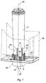
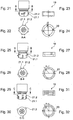
- FIG. 1 1 shows connection elements 1, 2 of a fragmentary, dashed-line tank 66 and an associated filter cartridge 31.
- a connection socket 1 is shown, which is firmly connected to the bottom 29 of the associated tank 66, for example welded, glued or otherwise secured.
- the tank connection element 2 of the filter cartridge 31 is inserted.
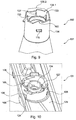
- the filter-side tank connection element 2 is in Fig. 4 better to see and includes a connection piece 4, which merges into the cartridge housing 36.
- the filter section can be formed in upflow, in downflow or in combination with both flow guides. Through the central outflow pipe 35, the filtered water finally reaches the suction connection 67 water tanks 66 via the tank-side device connection 68.
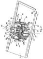
- FIGS. 1 and 2 Essential to the invention details are now with reference to the FIGS. 1 and 2 detailed below.
- a blending device 60, 65; 136.1, 160, 165; 336.1, 360, 365 proposed.
- unfiltered and / or otherwise treated water can be added to the filtered water stream leaving the filter 31.
- This may be useful, for example, if the filter has a better filtering effect than that required for proper operation of the operated with this tank device or if, for example, the filled water in the tank has a very good quality.
- the Verschneide In order to be able to fine-tune to certain applications and / or certain water qualities for the operation of the device, it is proposed in a further advantageous manner, the Verschneide worn so adjustable or adjustable form that an influence on the effective cross-section of unfiltered and / or otherwise treated the filtered water flow zugemengten bypass flow is possible.
- elements 6, 60 and 65 of the blending device in the connection region of the tank filter port 1,2 are aligned with each other so that they form a liquid-conducting channel, and that a direct flow of fresh water in the tank 66 in the central drain region of the suction port 67th is possible.
- the relevant, filter-side waste elements of the tank connection are in the FIG. 4 as formed in the housing wall 36 slots 6 and in a here exemplified as a hexagon formed form seal passages 60 shown.
- FIG. 2 two differently sized in their effective passage cross-section bypass openings 65 located in a side wall of the terminal socket 23, depending on the coverage of one of the three to FIG. 4 described recesses 60 are released or closed.
- the cutting adjustment described here is merely exemplary and may well by a combination with other recesses 60 and / or bypass openings 65 in the same and / or other side walls of here also exemplified as a hexagon, polygon-shaped tank and filter-side connection elements 1,2 finely graded dimensioned become.
- a tank-side device connection 68 is shown here for the sake of simplicity only as an example round-shaped connection piece.
- the tank-side device connection 68 can also have coding structures to ensure that only permissible connection connections can be made, ie both with a filter cartridge to be used for the tank and, if desired, with one for the use thereof Tanks suitable device.
- a graphic illustration of such details for the device connection 68 is omitted and with regard to the embodiments of codings possible for this purpose, reference is made to the embodiments described with regard to the tank-filter connection, which also apply in full to the tank device connection Have validity.
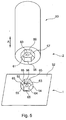
- a further and / or additionally possible embodiment of a tank-side filter cartridge coding is in the Figures 2 and 5 shown as a tank-side filter connection element, the peripheral surface 33 has a respect to the filter connection piece 2 axially aligned coding structure with a polygonal cross-section.
- the polygon is representative of a variety of other possible embodiments of tank filter ports as a hexagon.
- tank-side filter connection element 23 in the form of a connection socket 23, is designed to realize its polygonal contour as an axial projection 23 with a polygonal outer periphery 24.
- the complementary cartridge connection structure is preferably in a form-locking and sealing manner in a first possible fastening shape with its inner circumference 33 on the outer circumference 24, fixing and sealing the filter cartridge 31.
- the tank-side filter connection socket 23 and the connecting piece 4 of the filter cartridge surround.
- the tank-side filter connection socket 23 and the connecting piece 4 of the filter cartridge surround.
- the tank-side filter connection element 23 formed as a complementary structure in the form of an axial recess with a corresponding inner circumference, which in turn the sealing surface 33 of the filter cartridge preferably can fit positively and surface sealing, thereby in turn at the same time sufficient fixation of the filter cartridge 31 is ensured on the tank 66.
- the inserted filter cartridge 31 is provided with a molded seal 32, which accordingly also has a hexagonal cross-section (see FIG. 3 ).
- the inner surface of the molded seal 32 forms the sealing surface 33.
- FIG. 3 In addition, the inlet slots 34 for supplying water into the filter cartridge and a central drain opening 35 for the drainage can be seen. From the representation of bypass openings in the molded seal 32 has been here for reasons of clarity with reference to the FIG. 4 apart.
- the illustrated embodiment comprises further coding structures.
- snap elements 37 are formed on the outside of the filter cartridge housing 36 .
- the snap elements 37 can be inserted into corresponding receptacles 38 of the outer shells 25.
- the filter cartridge 31 can easily sit in the correct angular position without resistance.
- the molded seal 32 is aligned with respect to the sealing surface 24 of the connection socket 23, so that it can be further inserted in the axial direction.
- the snap element 37 snaps over the stop 40, wherein the molded seal 32 is pressed along the sealing surface 24. Due to the bevel of the snap elements 37 and the corresponding inner shape of the outer shells 25, the filter cartridge 31 is fixed in the outer shells 25. Further axial fixing elements are no longer required in this embodiment.
- Fig. 5 shows a further schematically illustrated embodiment of the invention with angle-dependent adjustable amount of waste.
- the tank bottom 52 is only partially shown in the connection area of the filter cartridge 53.
- the tank bottom 52 comprises a hexagonal connection base 54, which slightly converges towards the top in order to improve the sealing effect in relation to a purely vertical alignment of the base walls and / or as a further coding structure in the manner of a truncated pyramid. This cross-sectional taper is barely visible in the perspective view.
- the outer surfaces 55 of the terminal socket also serve as a sealing surface to seal the drain line 56 with the filter cartridge 53 mounted completely or partially with respect to the interior of the tank.
- the filter cartridge 53 has a socket-shaped seal 57 corresponding to the connection socket 54.
- the individual walls 58 are the same length except for a wall 59 in the axial direction A.
- the wall 59 is provided with a lower-side recess 60, whose Function will be explained in more detail below.
- the outlet 61 can be seen from the filter cartridge 53 through which the filtered water enters the drainage line 56.
- bypass openings 65 are arranged so that they are sealed by the longer sealing walls 58 when attaching the filter cartridge 53. Only where the wall 59 with recess 60 is used can the bypass openings 65 remain open, so that water filtered via the recess 60 directly from the tank to the region of the discharge line 56.
- the angular arrangement of the filter cartridge i. with the selection of the base wall 62, 63, 64, to which the recess 60 is attached, the size of the free cross section of the bypass openings 65 set.
- the cross-sectional openings of the multipassed bypass ports 65 add up.
- differently sized bypass ports 65 may also be provided. Due to the different cross sections of individual bypass openings 65 or in the sum of several bypass openings 65 on a base wall, for example, the base wall 64, different proportions of unfiltered water, the filtered water are added. This results in a blend setting, which is dependent on the angular position of the filter cartridge 53.
- a blend adjustment for example, by the formation of an actuatable by the filter cartridge driver element in the shape of a rotatably adjustable in its position terminal socket 54.1 according to the Dartellung in the FIG. 5a will be realized.
- the bottom 54.2 of the rotatable connection socket 54.1 here has, for example, three bypass openings 65.1 and, depending on the rotational position relative to the tank bottom 52, can be arranged such that complementary bypass openings 65.2 arranged in the tank bottom 52 are released or closed in a fluid-conducting manner.
- bypass holes 65.1 are shown purely by way of example, the rotational position shown with closed bypass and three other positioning options, with the release of one, two or all three bypass holes 65.1 by matching their position with the corresponding bypass holes 65.2.
- a possible separation variant between the bypass holes 65.1 and the centrally arranged discharge line 56 connected to the tank-side fresh water connection would be the arrangement of an intermediate seal, in particular and preferably an axial seal, which sealingly extends between the end face of the filter-side tank connection element and the bottom 54.2 of the connection base 54.1.
- Conceivable are also quite possibly other additional separating and / or sealing elements between the fresh water side and the side of the filtered water.
- FIG. 6 Finally, next to one shows in comparison to the embodiments in the FIGS. 1 to 4 described socket filter connection in the form of an axial projection 23 on the tank-side filter connection element 23 has a complementary shape than in the tank bottom 29 formed axial recess 23, in which mutatis mutandis, all coding possibilities described in the first embodiment can also be realized here, and indeed the same.
- the second essential feature shows the FIG. 6 the possibility of using adapters 85, 86.
- the adapter 85 is shown purely by way of example for connecting a filter cartridge 73 also shown as an example to a tank-side filter port 1, wherein the embodiment of the filter port 1, in particular its base 23, as already set forth above, as axial protruding base can be realized.
- the illustration of details of the trimming device has been given by reference to the examples in FIGS Figures 5 and 5a Apart from that, however, such embodiments are also possible here in a corresponding manner.
- the illustrated embodiments also show the most diverse coding structures that are to be provided according to the invention. In any case, it is ensured that only suitably adapted filter cartridges with key function fit into the corresponding tank-side filter connections.
- FIGS. 7 to 14 a tank filter cartridge connection not according to the invention with blend adjustment elements 106, 136.1, 160 and 165 as well as with encryption or coding structures aligned axially with respect to a longitudinal axis of the connection in combination with a further embodiment of a form-locking seal is described.
- corresponding features with the same basic numbering, but increased by the number 100, are already designated for the previously described embodiments.
- FIG. 7 a non-inventive tank-side connecting piece 104 in which a filter cartridge 131 is connected via a filter-side tank connection piece 101.
- the housing 136 of the filter cartridge 131 is completely in the tank-side connecting piece 101.
- the front end of the cartridge housing 136 is in the FIG. 8 shown behind a passage slot 106 for the inflow of fresh water in the tank into the interior of the connecting piece 101.
- a recess 160 is shown in the form of a bore, which has the function of a waste element, and fresh water flow through them and through another, arranged behind it, not visible here opening 165 in the Filterauslass Society 135 leaves in which the filtered from the cartridge water in the tank outlet 168 is passed.
- the blend setting can also be changed here, for example via corresponding rotational positions, if a version with adjustable, effective Verschneidequerites is provided.
- a fixed blend setting is possible, for example, is independent of a rotational position.
- a receiving guide track 115 for receiving a radial projection 116 formed on the filter cartridge is illustrated thereon.
- Both have a catch element 117 and 118, each complementary to the other, which snap into each other after a corresponding rotational movement upon insertion of the filter-side tank connection element 102 after overcoming corresponding clamping forces of the part projecting like a wing from the tank-side connection piece.
- the locking element 117 has a thickening in its front region, based on a required for the use of the filter cartridge rotational movement, which faces a correspondingly large recessed area in the locking element 118, thus a position-locking locking of the two connection elements can be ensured.
- the filter-side tank connection region not according to the invention is shown in the filter cartridge 131, wherein the housing 136 in the front, frontal region has a protrusion 136.1 projecting opposite recesses 136.2, each comprising the passage opening 160 already described above as a waste element.
- the projections 136.1 of the filter cartridge housing 136 in turn represent axially aligned coding structures, which enable a proper use of the filter cartridge in the relevant tank connection element.
- the embodiment described here has in each case three axially aligned coding structures 136.1 on the filter housing 136, which are arranged in particular preferably offset by 120 ° at the end of the circumference of the filter-side tank connection element 102, as shown in FIG. 9 good removable.
- the complementary connection elements of the tank-side filter connection 101 shows the FIG. 10 ,
- FIGS. 11 and 12 show two further views of this non-inventive embodiment of a tank filter port 101, 102.
- three axial recesses 101.1 are shown here, which are recessed in the tank bottom 129 to accommodate the three complementary housing projections 136.1 of the filter cartridge.
- axial projections 136.1 or complementary axial recesses 101.1 are again shown here as an encryption or coding structure for preventing filter cartridges not intended for the intended purpose.
- FIG. 13 shows a section through a non-inventive tank-side filter connection element 101 in which a filt.er knewes tank connection element 102 is inserted.
- the bypass or short-circuit openings 165 which are essentially closed by the three housing projections 136.
- FIG. 14 shows a further sectional view through the tank bottom 129 and a non-inventive tank side filter port 101 and a filter-side tank port 102 inserted therein viewed from the bottom side of the tank ago.
- the bypass or short-circuit lines 106 and 165 can be seen very well, which show a corresponding passage of the unfiltered fresh water into the tank outlet region 168.
- inserted cartridge with correct axial coding takes place a correspondingly provided waste of fresh water to be filtered by the formed in the wing-like protruding housing sections 136.1 by-pass holes 160th
- three axial coding structures shown here by way of example four, five or for example six such structures may be formed.
- the distance between the individual complementary axial coding structures can be either symmetrical or unbalanced.
- FIGS. 15 to 20 show further non-inventive embodiments of tank-side filter exclusion elements and filter-side tank connection elements, which are already substantially described with waste structures 306, 336.1 and 365 of a waste device in the sense of the above statements to the number ranges 0 to 99 and 100. Accordingly, for the sake of simplicity, features described hereinbefore with the previously described embodiments are also designated with the same basic numbering, but increased here by the number 300. They also have axially coded connection structures, in which axial coding structures 336.1, 336.2 and 337, for example, are formed for the respectively illustrated, filter-side tank connections, which are arranged in different angular positions relative to each other for differentiation.
- the tank-side filter connections 301 show the complementary axially coded connection structures of the respectively associated tank-side filter connection elements as further possible embodiments of different coding structures.
- FIGS. 21 to 32 show further possible non-inventive embodiments of encryption and / or fixation structures for tank filter connection elements. This show the FIGS. 21 to 24 a first, the FIGS. 25 to 28 a second and the FIGS. 29 to 30 a third possible embodiment of bayonet, in particular double or multiple bayonet as a complement to those already in the FIGS. 7 to set forth embodiments.
- FIGS. 21 to 32 show the non-inventive filter-side Tankan gleichkodier- or fixing structure with in plan view corresponding FIG. 22 eight projections 21.1 and 21.2, according to the FIG. 21 along the longitudinal extension of the filter-side tank connection element both axially and in a radial angular position offset from each other as two pairs of four are formed.
- the complementary non-inventive connection or .. Codier Weg 20 are in the tank-side filter connection element 19 in the FIGS. 23 and 24 shown.
- the front side to the front arranged coding projections 21.1 must be distributed according to the circumferential distribution of the openings 20 on the tank-side filter connection element 19, so that even an axial insertion of the filter-side tank connection element is made possible.
- FIGS. 25 to 28 represent similar embodiments not according to the invention, but with respect to the embodiments 21 to 24 modified contours of the openings 20 and the thereto complementary coding projections 21 as well as with respect to axially and viewed in plan view angularly changed orientations.
- Embodiments 21 to 24 there are a total of eight on two levels and in Embodiments 25 to 28 only six as two triple-coded protrusion levels respectively.
- these coding structures described herein may readily be combined with other e.g. axially aligned coding structures are combined to allow even further differentiation possibilities for individual tank-filter connection connections.
- FIGS. 33 to 40 2 shows a further embodiment of a tank filter connection connection in different views and illustrations, such as oblique top views, sectional views, front view and bottom view of the filter cartridge 29 and a top view of the tank-side filter connection element with and without an inserted filter-side tank connection element (FIG. Fig. 39 and 40 ).
- the essential features of the embodiment of a tank filter connection connection are the frontally projecting from the filter cartridge 31, such as wedge-shaped tips S and arranged between them grooves N.
- the geometrical dimensions and angular positions of these tips S and benefits N to each other allow different codes or Fixing points for the filter-side connection element on the tank side, filter connection element.
- the tips can also be used for positioning when inserting the filter cartridge in the tank connection piece, in particular in optically not visible connections, eg to avoid damage to the sealing and / or other Structures.
- the slot spacings and / or the slot widths and / or the widths of the tips or projecting wings as well as their lengths and / or distances, which must correspond to corresponding structures on the tank-side filter connection element, are particularly suitable for coding Filter cartridge to allow.
- ribs R formed on the tank-side filter connection element.
- FIG. 39 whose interaction with the coding and / or fixing structures N and S formed on the filter-side tank connection element are best described in US Pat FIG. 40 are recognizable.
- the ribs R are in this case formed on a filter-side tank connection element partially enclosing, wall-shaped base SO.
- the coding and / or fixing structure described above may also be designed to be complementary in a modified embodiment, ie grooves instead of ribs and ribs instead of grooves.
- a mixed or combined coding and / or fixing structure by forming grooves and ribs on the one and / or other tank or filter-side connection element is quite possible.
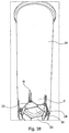
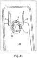
- FIGS. 41 to 43 represent a further embodiment in which the filter 31 arranged along a tank wall, two angularly shaped ribs R having and engaging in two complementary slots S guide is inserted into the interior of the tank.
- the tank has in its bottom 29 a polygonal, here hexagonal, filter connection element 23 and one of within this connection element through the tank wall to the outside leading tank drain opening 35.
- the polygonal connecting element 23 is formed as at the bottom of the tank with bevelled at its top polygon.
- the filter-side tank connection element 32 in the form of a conically shaped, likewise polygonal shaped seal 32 has a correspondingly complementary inclined connection surface.
- a bypass structure may be formed to allow a blending of the filtered water.
- a supplementary rib-shaped structure R and a complementary slot-shaped coding structure S are formed here by the end-side recess S in the filter wall and the complementary shape R of the outlet opening 35 in the bottom region of the tank wall. These too can be modified accordingly, e.g. in a square shape, a triangular shape or other as well as further recesses and / or projections having structure to distinguish differently approved filter types.
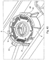
- FIGS. 44 to 47 Another embodiment of a square coding for a tank-filter connection are through the FIGS. 44 to 47 shown.
- This embodiment has, in addition to those in the FIG. 6 illustrated embodiment, a bypass structure on.
- This bypass structure comprises, based on the in the FIGS. 7 to 20 illustrated bypass structure in the front-side housing extension of the filter cartridge 73 has an opening in the form of a bore 160 which in overlapping with an opening formed in a tank side filter base connection port 165 165 the flow of raw water in the tank to the tank-side device connection in the discharge area of the tank Admixture with the filtered through the filter cartridge water allows.
- the bypass opening 160 is formed on the filter side in the end extension of the filter and realizes a waste device in combination with the tank-side filter connection element 77.
- a further waste structure can be realized by forming a bypass opening 160.1 in the polygonal, filter-side tank connection element 32, here in the form of a four-edged molded seal 32, which in turn corresponds to the opening 165 formed in the tank-side filter connection 77.
- the size of the opening 161.1 in turn determines the amount of waste.
- the waste device is realized directly in the sealing region of the polygonal-shaped tank filter connection.
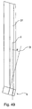
- FIGS. 48 and 49 show an embodiment of a tank-filter connection, in which a through the filter-side tank connection element 4 extending longitudinal axis II is obliquely aligned with respect to a running through the housing of the filter cartridge 31 longitudinal axis I, here preferably at an acute angle ⁇ .
- This oblique or even cranked or also beveled orientation of the filter-side tank connection element 4 relative to the rest of the filter housing forms a further form of mechanical coding, which can be combined with other, already described above, coding forms, in particular with a polygonal connecting element shown here in the form of a octagon.
- This octagon may preferably also be formed as a molded seal and, as shown here, a bypass or Verismevoriques in the form of an opening 160 which allows in the presence of a complementary element in the tank-side filter connection element a corresponding waste of the water to be filtered.
- FIG. 48 shows the filter cartridge 31 in an oblique view from below, in which the filter-side connection element 4 and its essential features can be seen.
- FIG. 49 a side view in which the bend between the cartridge housing 31 and the filter-side tank port 4 is shown for an exemplary angle shown.
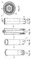
- FIG. 50 shows a further embodiment in which the tank 66 is again designed as a Einschubtank in which a cartridge 31 is connected to filter the water contained therein to a tank workedem filter connection element 2.
- This tank-side connection element 2 is connected via a line, here preferably in the form of a stable tube, to the tank-side device connection 68.
- This tank-side device port 68 is the appropriate operation bottom side portion of the tank 66 spaced from the tank interior led to the outside.
- the device connection 68 is fixed by way of example in a recess embedded in the upper edge of a tank wall, which can be advantageously designed as a releasable connection, so that an easy removal and cleaning is made possible.
- the operation of the tank is possible by simply inserting into a suitably trained recording a device, or its filling with fresh, then filtered through the filter 31 by pulling out water.
- the tank-side filter connection element 2 may in this case all coding and / or fixing and / or sealing features described above, so that in this drawer embodiment reliably the use of a non-operationally provided filter cartridge can be unlocked, which incidentally also for the execution of the FIGS. 41 to 43 applies.
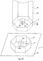
- FIG. 51 Two other possible non-inventive embodiments of codings of the connection between the tank and filter are based on the Figures 51 and 52 shown and described.
- the housing of the filter cartridge 53 itself has a polygonal outer contour in the form of a hexagon, which can be inserted into a complementary tank-side polygonal coding and / or fixing structure 23.
- the solid lines show the filter cartridge 53 in a view obliquely from below with a basically flat bottom in the middle of the filter outlet 35 for the filtered water is exemplified as a cylindrical protruding tube with two end-side axially projecting lugs 35.1 and 35.2.
- This cylindrically projecting outlet element 35 is coded by the two axially projecting wings and forms with its end face opposite the end face of a complementary tank-side filter port
- Outlet and receiving element 68 with its at the coding grooves 68.1 and 68.2 an axial coding and / or sealing structure or contour.
- the filter cartridge 53 can only be plugged into the tank-side filter connection element 1 in a functional manner if the end face of the filter outlet 35 sealingly mates with the end face of the tank-side device outlet 68.
- the hexagonal outer contour of the filter cartridge 53 exemplified here in the embodiment shown by the solid lines, can not be inserted into the connection socket 23 of the tank-side filter connection element 1 in a fixing manner and optionally also sealingly.
- the inner circumference of the connection base 23 serves for fixing and optionally for sealing against the outer circumference or against the connection thereof.
- the housing 36 of the filter cartridge 53 is shown by the dashed lines as compared to the previously described filter bottom extended.
- This polygonal, opposite the bottom of the filter cartridge protruding connecting ring can be used to fix the filter cartridge via the tank-side filter connection piece 23, again fixing and preferably sealing depending on the version, slipped over or plugged in until the two inner encodings, the filter outlet 35 and the tank outlet 68, sealingly abut each other or their wing-like and complementary slot-like coding structures shown here by way of example, sealingly abut each other or interlock.
- FIG. 51 shows both a fixation of the filter cartridge on the inner circumference of the tank-side filter connection element 23 and on the outer circumference 24th
- FIG. 52 In contrast, according to the invention, an embodiment modified in such a way that the housing 36 of the filter cartridge is shown as an example and the filter outlet 35 as a polygonal structure, here again by way of example as a hexagon, in addition again an end-face coding in the form of two axially projecting, coding, triangular tips or wings.
- the filter cartridge can only be operatively connected to the tank-side filter connection element 1, when the two outlet structures 35 and 68 can be attached to the front side axially sealingly to each other.
- the presentation of further coding and / or fixing structures was considered for reasons of clarity. However, all the structures already described above can also be provided accordingly here. Also for the two embodiments according to the Figures 51 and 52 applies that these coding structures between the filter side and tank side can be reversed and / or modified and / or supplemented by other contours and / or structures.
- FIGS. 53 to 56 Two further embodiments with respect to a bypass configuration between a tank-side filter connection element 1 and a filter-side Tankan gettinglement 2 are in the FIGS. 53 to 56 shown.
- the FIGS. 53 and 54 not inventive show here by way of example and schematically a bypass arrangement BY, which is a blend between filtered through the filter cartridge 53 and a water not or otherwise filtered or processed Water allows.
- the bypass or blending line BY is in this embodiment combined with a bayonet catch BJ in such a way that an opening BY is provided in a bayonet wing BJ which corresponds to a further bypass opening BY arranged on a bayonet slot BJ which is complementary to the bayonet wing Inserted filter cartridge a corresponding bypass guide is realized.
- the bypass opening BY shown in the tank-side filter connection element 1 is guided from the front-side connection region of the tank-side connection socket to below the point in which the filter-side tank connection piece 4 ends in operationally inserted position, so that the past the filter bed of the filter cartridge 53 bypass water with the water filtered through the filter bed of the filter cartridge 53 is mixed and supplied to the tank-side device connection 68.
- FIGS. 55 and 56 show a contrast modified embodiment, that the bypass line BY is guided over a separate from a main filter bed HF of the filter cartridge 53 processing and / or filter section, which is exemplified here and symbolically as Maufilterumble NF.
- This second treatment and / or filter section NF may contain, for example, an activated carbon filter section and / or other treatment mechanisms and / or media.
- the water guided via this bypass section BY is mixed with the water filtered through the filter section HF of the filter cartridge 53, so that it can likewise be removed through the tank-side device connection 68.
- FIG. 56 shown embodiment of the filter cartridge 53 is the merger of the two separately guided over the main filter HF and the secondary filter NF or processed water lines in the interior of the filter cartridge 53 by an opening into the inner downpipe of the filter cartridge 53 exemplified and shown schematically.
- a separate outlet opening out of the filter cartridge may well be provided in the direction of the tank-side appliance connection 68, where applicable for all three embodiments, that they all open inside the tank-side filter connection nozzle 32, so that in turn For example, a seal by a positive connection of the two polygonal connection elements of the tank and the filter are possible.
- the introduction of the bypass flow in the secondary filter section is only possible if the opening also acting as coding opening BY is plugged into the axially from the tank bottom 29 high encryption element 25 with the corresponding filter-side bypass opening BY in the operationally provided state. If no overlap of these two openings is given, then no corresponding waste can be realized.
- the tank-side filter port 1 according to the FIG. 55 is likewise shown only schematically and by way of example and can be provided with a wide variety of variants of the coding and connection structure already described above, so that optionally only a single one of all six possible angular orientations for an allowable filter termination is enabled. From the representation of such coding structures was omitted at this point for reasons of clarity.
- FIGS. 53 to 56 Basically, also applies to these embodiments in the FIGS. 53 to 56 in that they too can be combined with all the coding and / or fixing and / or sealing structures described above and / or.
Description
Die Erfindung betrifft einen Wassertank mit Filterpatrone nach dem Oberbegriff des Anspruchs 1.The invention relates to a water tank with filter cartridge according to the preamble of
In verschiedenen Maschinen, beispielsweise in Kaffee- oder Espressomaschinen wird ein Wassertank zur Bevorratung einer Flüssigkeit, im Falle von Kaffee- oder Espressomaschinen zur Bevorratung von Wasser, vorgesehen, wobei eine Filterpatrone in den Tank einsetzbar ist, um das Wasser vor der Verarbeitung in der Maschine aufzubereiten. Bekannte Filterpatronen weisen im unteren Bereich einen Einlass auf, durch den das Wasser seitens der zugehörigen Maschine angesaugt wird. Hierbei wird das Wasser über ein Filterbett geleitet und gelangt über einen Anschluss der Filterpatrone an einen entsprechenden Sauganschluss des Wassertanks in die Maschine.In various machines, for example in coffee or espresso machines, a water tank is provided for storing a liquid, in the case of coffee or espresso machines for storing water, wherein a filter cartridge is inserted into the tank to the water before processing in the machine prepare. Known filter cartridges have at the bottom of an inlet through which the water is sucked in by the associated machine. Here, the water is passed through a filter bed and passes through a connection of the filter cartridge to a corresponding suction port of the water tank in the machine.
Für einen zuverlässigen Betrieb der Maschine ist es von großer Bedeutung, dass ihr nur Wasser mit einer zumindest den Mindestanforderungen entsprechenden Wasserqualität zugeführt wird, wozu vorzugsweise eine in ihren Filterparametern definierte Filterpatrone verwendet wird. Durch eine mangelhafte Filterpatrone wird der Maschine unzureichend oder falsch aufbereitetes Wasser zugeführt, was zu negativen Auswirkungen, beispielsweise Verkalkung oder dergleichen, bis hin zu Maschinendefekten führen kann. Die Maschinensteuerung ist nicht in der Lage, rechtzeitig die vorgesehenen Wartungsintervalle einzuleiten, wenn sie von einer Filterpatronen des korrekten Typs ausgeht., diese jedoch tatsächlich nicht verwendet wird. Bei der Verwendung ungenügender Filterpatronen kommt es zu Problemen nicht nur in der Betriebssicherheit der Maschine, sondern auch in Fragen der Gewährleistung usw. Es ist daher von großer Bedeutung sicherzustellen, dass stets nur zugelassene Filterpatronen zum Einsatz kommen.For a reliable operation of the machine, it is of great importance that it is fed only water with at least the minimum requirements corresponding water quality, for which purpose preferably a filter cartridge defined in their filter parameters is used. Due to a defective filter cartridge, the machine is supplied with insufficient or incorrectly treated water, which can lead to negative effects, for example calcification or the like, right through to machine defects. The machine control system is unable to initiate the scheduled maintenance intervals in a timely manner if they are being used by a Filter cartridges of the correct type starts, but this is actually not used. The use of insufficient filter cartridges causes problems not only in the operational safety of the machine, but also in questions of warranty etc. It is therefore of great importance to ensure that only approved filter cartridges are used at all times.
Andererseit.s ist es möglich, dass das zu filternde Wasser, bereits eine sehr hohe Qualität aufweist, so dass zumindest bei bestimmten Anwendungsfällen die vom einzusetzenden Filter erzielte Filterwirkung gar nicht in vollem Umfang von Nöten ist.On the other hand, it is possible that the water to be filtered, already has a very high quality, so that at least in certain applications, the filtering effect achieved by the filter to be used is not fully necessary.
Die
Der Erfindung kann daher die objektive Aufgabe zugrunde gelegt werden, Mittel zur zuverlässigen Wasseraufbereitung gemäß für einen bestimmten Anwendungsfall definierter Filterparameter vorzuschlagen. Die Lösung dieser Aufgabe erfolgt gemäß Anspruch 1 ausgehend von dem im Oberbegriff formulieren Wassertank mit Filterpatronen durch dessen Kennzeichen.The invention can therefore be based on the objective task of proposing means for reliable water treatment in accordance with filter parameters defined for a particular application. The solution to this problem is carried out according to
In den abhängigen Ansprüchen sind vorteilhafte und zweckmäßige Weiterbildungen angegeben.In the dependent claims advantageous and expedient developments are given.
Dementsprechend zeichnet sich ein erfindungsgemäßer Tank mit Sauganschlusselement zum Ansaugen von Wasser mittels Unterdruck aus dem Tank und einem Filteranschluss zum Anschluss einer Filterpatrone im Inneren des Tanks dadurch aus, dass eine Verschneidevorrichtung bzw. Verschnitteinstellung vorgesehen ist, mit der ein Bypassstrom von ungefiltertem oder auf andere Weise aufbereitetem Wasser am Filterbett vorbeigeführt wird. Hierdurch kann die Qualität des einem Wasser aufbereitenden und/oder verbrauchenden Gerät zugeführten Wassers z. B. anwendungs- und/oder gerätespezifisch durch Mischen des durch die Filterpatrone gefilterten und nicht durch sie gefilterten Wassers oder durch Mischen des durch eine Filterstrecke gefilterten Wassers mit durch eine oder mehrere anderweitige Filterstrecke gefilterten Wasser eingestellt werden. Im Weiteren kann so die Betriebslaufzeit dadurch optimiert werden, dass der Filter nicht eher ausgetauscht werden muss, als dies bei der Bereitstellung einer für den jeweiligen Anwendungsfall ausreichenden Wasserqualität durch Erschöpfung des Filtermaterials der Fall ist. Bei der Durchleitung einer im Vergleich geringeren Menge an Wasser aufgrund der erfindungsgemäßen Verschneidung des zu filternden Wassers kann daher das hierfür verwendete Filtermaterial aufgrund seiner dadurch über den zeitlichen Verlauf betrachtet geringeren Erschöpfung somit länger zur Verfügung stehen.Accordingly, a tank according to the invention with a suction connection element for sucking water by means of negative pressure from the tank and a filter connection for connection of a filter cartridge inside the tank is characterized in that a blending device or by-pass setting is provided, with which a bypass flow of unfiltered or otherwise recycled water is passed by the filter bed. As a result, the quality of a water processing and / or consuming device supplied water z. B. application and / or device specific by mixing the filtered through the filter cartridge and not filtered by them water or by mixing the filtered through a filter section water with filtered by one or more other filter section water. Furthermore, so the operating time can be optimized by the fact that the filter does not need to be replaced sooner than in the provision of one for the respective Use case sufficient water quality by exhaustion of the filter material is the case. When passing a comparatively smaller amount of water due to the invention, the intersection of the water to be filtered therefore the filter material used for this reason, therefore longer available due to its thus considered over the course of time lower exhaustion.
Unter einem tankseitigem Filterausschlusselement sind erfindungsgemäß direkt und/oder indirekt am Tank angeordnete und/oder ausgebildete Elemente zu verstehen, wie vorstehende und/oder vertiefte Aufnahme- und/oder Fixier- und/oder Kodier- und/oder Dichtelemente. Diese können z.B. als fest mit dem Tank verbundene oder verbindbar ausgebildete Ausschlussstutzen, als Haken, Ösen, Adapter oder dergleichen ausgebildet sein.Under a tank-side filter exclusion element are according to the invention directly and / or indirectly arranged on the tank and / or formed elements to understand how protruding and / or recessed receiving and / or fixing and / or coding and / or sealing elements. These may e.g. as firmly connected to the tank or connectable formed Ausschlussstutzen, be designed as hooks, eyes, adapters or the like.
Der tankseitige Filteranschluss ist hierbei vorzugsweise im Bodenbereich des Tanks ausgebildet. Er kann durchaus aber auch wenigstens teilweise oder auch vollständig in einer Ecke und/oder an einer Seitenwand des Tanks innen angeordnet sein, je nach dem an welcher Stelle der Anschluss zwischen dem Wassertank und einer geräteseitigen Abflussleitung vorgesehen ist. Zum Beispiel ist auch ein in einem vom Boden des Tanks in dessen betriebsmäßiger Einbaulage nach oben hin beabstandet aus dem Tank herausgeführtes tankseitiges Filteranschlusselement denkbar.The tank-side filter connection is in this case preferably formed in the bottom region of the tank. However, it may well also be arranged at least partially or completely in a corner and / or on a side wall of the tank, depending on where the connection between the water tank and a device-side drain line is provided. For example, a tank-side filter connection element which is led out of the tank at a distance from the bottom of the tank in its operational installation position is also conceivable.
Durch solche Ausführungsformen kann z.B. ein kannen- und/oder schubladenartiger Tank realisiert werden, in welchem wiederum nur eine mit einem entsprechenden kodierten filterseitigen Tankanschlusselement versehene Filterpatrone eingesetzt werden kann. Die geräteseitigen Verbindung des Tankanschlusses kann sowohl bei diesem als auch bei den vorbeschriebenen Ausführungsformen als Steckanschluss an ein entsprechend komplementäres geräteseitiges Tankanschlusselement angeschlossen werden. Das vom Tankboden beabstandete tankseitige Filteranschlusselement kann beispielsweise auch als an einer Tankwand einhängbares Filteranschlusselement ausgebildet sein, z.B. in der Form einer Rohrleitung, die bei eingesetzter Patrone mit entsprechend passender Kodierung zur Ausleitung des in den Tank eingefüllten und durch die Filterpatrone gefilterten Rohwassers dient.By such embodiments, for example, a can and / or drawer-like tank can be realized, in which in turn only one provided with a corresponding coded filter-side tank connection element filter cartridge can be used. The device-side connection of the tank connection can in this as well as in the embodiments described above as a plug connection to a correspondingly complementary device-side tank connection element be connected. The spaced apart from the tank bottom tank-side filter connection element may for example be formed as attachable to a tank wall filter connection element, for example in the form of a pipe which is used with inserted cartridge with appropriate matching code for discharging the filled into the tank and filtered through the filter cartridge raw water.
Bei entsprechend tiefliegender Anordnung der Wassereintrittsöffnungen für die Filterstrecke kann auch mit einer derartigen Ausführungsform der wesentliche Inhalt des Tanks entleert werden, so dass dieser keine oder nur eine geringe Menge an nicht durch die Filterstrecke führbares Todwässer aufweist.In accordance with low-lying arrangement of the water inlet openings for the filter section can be emptied with such an embodiment, the essential content of the tank, so that it has no or only a small amount of not feasible through the filter section dead water.
Insbesondere vorteilhaft kann die Verschneidevorrichtung hierbei so ausgebildet sein, dass die beizumischende Menge des ungefilterten oder auf andere Weise aufbereiteten Wassers einstellbar ist. Dies ist beispielsweise mit einer oder mehreren Bypassöffnungen möglich, die zur Einstellung der am Filterbett vorbeigeleiteten Wassermenge variabel einstellbar geöffnet werden. Eine solche Verschnitteinstellung kann beispielsweise über die Winkelposition der Einbaulage der Filterpatrone verwirklicht werden. In einer besonders bevorzugten Ausführungsform kann dies auch in Kombination mit einer Kodierungsstruktur mit der Vorgabe fester Winkelpositionen über die Einbaulage der Patrone erfolgen. Zu möglichen Kodierstrukturen wird nachfolgend noch näher Bezug genommen.Particularly advantageously, the blending device can be designed in this case so that the amount of unfiltered or otherwise treated water to be admixed can be adjusted. This is possible, for example, with one or more bypass openings, which are opened to adjust the amount of water passed by the filter bed variably adjustable. Such a blend adjustment can be realized for example via the angular position of the mounting position of the filter cartridge. In a particularly preferred embodiment, this can also be done in combination with a coding structure with the specification of fixed angular positions on the mounting position of the cartridge. Possible coding structures will be referred to in more detail below.
Die Verschnittmenge an ungefiltertem oder auf andere Weise aufbereitetem Wasser kann dabei durch entsprechend ausgebildete Öffnungen eingestellt werden, die das Tankinnere direkt mit dem Abfluss des Tanks verbinden, durch welche das durch die Filterpatrone gefilterte Wasser dem betreffenden Gerät zugeführt wird. Diese Öffnungen können je nach Einsetzwinkel der Filterpatrone, ggf. in Abhängigkeit einer solchen Kodierungsstruktur, unterschiedlich groß ausgebildet bzw. geöffnet sein und/oder in unterschiedlicher Anzahl geöffnet werden, so dass sich abhängig von der Einbaulage der Filterpatrone ein unterschiedliches Verschnittverhältnis ergibt oder der Verschnitt vollständig verschlossen ist.The amount of waste of unfiltered or otherwise treated water can be adjusted by appropriately trained openings that connect the tank interior directly to the drain of the tank, through which the filtered through the filter cartridge water is supplied to the device concerned. These openings may vary depending on Insertion angle of the filter cartridge, possibly depending on such a coding structure, formed differently or opened and / or opened in different numbers, so that depending on the installation position of the filter cartridge results in a different Verschnittverhältnis or the waste is completely closed.
So können beispielsweise bei einer sechskantförmigen Kodierungsstruktur im Anschlussbereich der Filterpatrone im tankseitigen Anschlussstutzen, der zur Verbindung mit der Filterpatrone vorgesehen ist, unterschiedlich große Öffnungen als Bypass vorgesehen werden, die beim Aufstecken einer Filterpatrone winkelabhängig verschlossen werden. Die Bypassöffnungen werden dabei in einer Ausführungsform bevorzugt in der Dichtfläche angebracht, so dass durch eine entsprechend geformte Anschlussdichtung der Filterpatrone beim Einsetzen der Filterpatrone alle Öffnungen mit Ausnahme der als Bypassöffnung vorgesehenen Öffnung abgedichtet werden. In einer andern Ausführung ist z.B. auch eine ein Betätigungselement umfassende Verschnittvorrichtung vorstellbar, bei der durch eine Einsetz- und/oder Positionierungsbewegung für die Filterpatrone ein bestimmtes Verschnittverhältnis eingestellt werden kann, wie nachfolgend anhand eines Beispiels noch näher erläutert wird.Thus, for example, in the case of a hexagonal-shaped coding structure in the connection region of the filter cartridge in the tank-side connecting piece, which is provided for connection to the filter cartridge, openings of different sizes can be provided as a bypass, which are closed depending on the angle when a filter cartridge is inserted. In one embodiment, the bypass openings are preferably mounted in the sealing surface, so that all openings except the opening provided as a bypass opening are sealed by a correspondingly shaped connection seal of the filter cartridge when inserting the filter cartridge. In another embodiment, e.g. It is also conceivable to include an actuating device comprising a cutting device, in which a specific mixing ratio can be set by an insertion and / or positioning movement for the filter cartridge, as will be explained in more detail below by means of an example.
Die Verschnittmenge kann z.B. aber auch auf andere Weise unter Nutzung der Kodierungsstruktur eingestellt werden. So kann beispielsweise eine Kodierungsstruktur zugleich als mechanischer Mitnehmer dienen, um ein Verstellelement im Tankbereich durch die Filterpatrone mechanisch zu betätigen. Im Falle eines sechskantförmigen Anschlusssockels im Tankbereich könnte beispielsweise eine entsprechende Sechskantkontur der Filterpatrone dazu dienen, um ein verdrehbares Sockelelement zur Verschnittmengeneinstellung zu verdrehen. Die sechskantförmige Kodierungsstruktur der Filterpatrone hätte sodann nicht nur Kodierungsfunktion, sondern wäre zugleich ein mechanisches Betätigungselement, gewissermaßen nach Art eines Sechskantschlüssels.However, the amount of waste can also be adjusted in another way using the coding structure, for example. Thus, for example, a coding structure at the same time serve as a mechanical driver to mechanically actuate an adjustment in the tank area through the filter cartridge. In the case of a hexagonal connection socket in the tank region, for example, a corresponding hexagonal contour of the filter cartridge could serve to rotate a rotatable base element for the purpose of adjusting the amount of waste mixture. The hexagonal coding structure of the filter cartridge would then not only have coding function, but at the same time would be a mechanical actuator, as it were in the manner of a hex wrench.
In einer besonders bevorzugten Ausführungsform ist somit eine Kombination der oben beschriebenen Verschneidevorrichtung bzw. Verschnitteinstellung der Tank-Filterverbindung mit einer ebenfalls hierfür vorgesehenen Kodierstruktur vorgesehen. In einer besonders bevorzugten Ausführungsform der Kodierstruktur kann der Filteranschluss des Tanks mit weinigstens einer, wenigstens einen axialen Vorsprung umfassenden mechanischen Kodierungsstruktur versehen sein, die zu einer komplementären, dementsprechend wenigstens eine Ausnehmung und/oder wenigstens einen Vorsprung umfassenden Kodierungsstruktur der Filterpatrone passt.In a particularly preferred embodiment, a combination of the above-described blending device or blending setting of the tank filter connection with a coding structure also provided for this purpose is thus provided. In a particularly preferred embodiment of the coding structure, the filter connection of the tank can be provided with at least one mechanical coding structure comprising at least one axial projection, which matches a complementary coding structure of the filter cartridge corresponding to at least one recess and / or at least one projection.
Weiter ist auch eine polygone Verschlüsselungs- und/oder Ansehlussstruktur für den Tank-Filter-Anschluss vorgesehen, auf welche ebenfalls im nachfolgenden Text noch näher Bezug genommen wird. Das ergibt eine Kombination von in Bezug auf den Anschlusssockel axial ausgerichteter und polygoner Kodierungsstrukturen, ggf. zusätzlich noch in Kombination mit radial ausgerichteten Kodierungsstrukturen.Furthermore, a polygonal encryption and / or Ansehlussstruktur is provided for the tank-filter connection, which is also referred to in the following text even closer reference. This results in a combination of axially aligned and polygonal coding structures with respect to the terminal socket, if appropriate additionally in combination with radially oriented coding structures.
Die Strukturen am Filteranschluss des Tanks müssen somit nach einem Schlüssel-Schlossprinzip mit entsprechenden Anschlussstrukturen einer Filterpatrone wechselwirken, damit die Filterpatrone funktionsfähig in den Wassertank einsetzbar ist. Ein Maschinen- bzw. Tänkhersteller kann auf diese Weise dafür Sorge tragen, dass nur Filterpatronen zum Einsatz kommen, die einen zuverlässigen Betrieb der Maschine gewährleisten. Der Unterdruck zum Absaugen kann beispielsweise über eine Saugpumpe erzeugt werden. Zusätzlich zu derartigen axialen Vorsprüngen und/oder Ausnehmungen können auch in radialer Richtung des Filteranschlusselementes bzw. der Filterpatrone Verschlüsselungselemente vorgesehen werden.The structures at the filter connection of the tank must thus interact with corresponding connection structures of a filter cartridge according to a key-lock principle so that the filter cartridge can be inserted into the water tank in a functional manner. In this way, a machine or dancer manufacturer can ensure that only filter cartridges are used that ensure reliable operation of the machine. The vacuum for suction can be generated for example via a suction pump. In addition to such axial projections and / or recesses encryption elements can also be provided in the radial direction of the filter connection element or the filter cartridge.
Besonders vorteilhaft werden der Filteranschluss des Tanks und ein Anschlussstutzen der Filterpatrone so ausgebildet, dass diese einander umschließen. Insbesondere in einer solchen Ausführungsform können beispielsweise zur Ergänzung axial ausgerichteter Kodierungsstrukturen, z.B. zur weiteren Differenzierung der Verschlüsselungsstruktur, wie für verschiedene Anwendungsfälle und/oder Kunden auch solche in radialer Richtung, d. h. quer in Bezug auf die Achse des Anschlussstutzens der eingesetzten Filterpatrone angeordnet werden. Diese können ohne Weiteres mit unterschiedlichsten axialen Kodierungsstrukturen kombiniert werden, beispielsweise an der Stirnseite des Anschlussstutzens oder im Bereich des Tankbodens.Particularly advantageously, the filter connection of the tank and a connecting piece of the filter cartridge are formed so that they enclose each other. In particular, in such an embodiment, for example, to supplement axially aligned coding structures, e.g. for further differentiation of the encryption structure, as for different applications and / or customers also in the radial direction, d. H. be arranged transversely with respect to the axis of the connecting piece of the filter cartridge used. These can readily be combined with a wide variety of axial coding structures, for example on the end face of the connecting piece or in the region of the tank bottom.
Vorzugsweise werden die Kodierungsstrukturen wenigstens teilweise zugleich als Fixierungselemente zur Befestigung der Filterpatrone ausgebildet. In diesem Fall werden den Kodierungsstrukturen bevorzugt hinterschneidend ausgeführt, so dass beispielsweise durch Drehen oder durch Klipsen eine Fixierung der Filterpatrone am Tankboden bzw. einem am Tankboden angebrachten Befestigungselement stattfinden kann, wobei selbstverständlich die entsprechenden Kodierungsstrukturen zueinander passen müssen, um einen einwandfreien Betrieb mit korrekter Filterpatrone sicherzustellen.Preferably, the coding structures are at least partially formed at the same time as fixing elements for fastening the filter cartridge. In this case, the coding structures are preferably performed undercutting, so that for example by rotation or by clipping a fixation of the filter cartridge on the tank bottom or a mounted on the tank bottom fastener can take place, of course, the corresponding coding structures must match to proper operation with the correct filter cartridge sure.
Kodierungsstrukturen können grundsätzlich auch als Betätigungsorgane im Bereich des Tankanschlusses herangezogen werden. So kann beispielsweise ein am Tank angebrachter Schaltmechanismus mit den Kodierungsstrukturen der Filterpatrone betätigt werden, der zur Signalisierung des durch die Position der Filterpatrone eingestellten Verschnittverhältnisses und/oder des korrekten Sitzes der Filterpatrone und/oder zur Erkennung des richtigen Typs von Patrone durch das zugehörige Gerät dienen kann. Eine solche Ausgestaltung der Kodierungselemente als Betätigungsorgan ist bei allen anderen Arten von Kodierungsstrukturen möglich.In principle, coding structures can also be used as actuators in the area of the tank connection. For example, a switching mechanism mounted on the tank may be actuated with the coding structures of the filter cartridge used to signal the cut ratio set by the position of the filter cartridge and / or the correct seating of the filter cartridge and / or to detect the correct type of cartridge by the associated apparatus can. Such an embodiment of the coding elements as an actuator is possible in all other types of coding structures.
Der Filteranschluss des Tanks ist mit einer Umfangskontur in Form eines Polygonzugs versehen. Eine derartige Formgebung ermöglicht darüber hinaus bei entsprechender Strukturierung der axialen, und sofern verwendet auch radialen Kodierungsstrukturen eine weitergehende Winkelkodierung für verschiedene Einsatzwinkelpositionen der Filterpatrone.The filter connection of the tank is provided with a circumferential contour in the form of a polygon. Such a shaping also allows, with appropriate structuring of the axial, and if used also radial coding structures a more extensive angular coding for different insertion angle positions of the filter cartridge.
Vorzugsweise wird zu diesem Zweck eine drehsymmetrische Umfangskontur am Filteranschlusselement vorgesehen. Mit Hilfe einer drehsymmetrischen Ausgestaltung sind verschiedene, vorbestimme Winkelpositionen beim Einsetzen einer Filterpatrone realisierbar, denen bei Bedarf eine Zusatzfunktion je nach Wickelposition zugeordnet werden kann. Ein Beispiel für eine Umfangsform des tankseitigen Filteranschlusselementes nach den oben beschriebenen Ausführungsbeispielen wäre beispielsweise mit einer Sechskant-Querschnittskontur gegeben. Eine solche Kontur lässt z. B. sechs verschiedene Winkelpositionen einer dazu korrespondierenden Filterpatrone zu. Entsprechendes gilt für Vierkant-, Sechskant-, 8-kant oder dergleichen Strukturen.Preferably, a rotationally symmetrical circumferential contour is provided on the filter connection element for this purpose. With the help of a rotationally symmetrical design are different, predetermined angular positions when inserting a filter cartridge feasible, which, if necessary, an additional function can be assigned depending on the winding position. An example of a peripheral shape of the tank-side filter connection element according to the embodiments described above would be given for example with a hexagonal cross-sectional contour. Such a contour can be z. B. to six different angular positions of a corresponding filter cartridge. The same applies to square, hexagonal, 8-edged or similar structures.
Das tankseitige Filteranschlusselement ist dabei als Vorsprung mit entsprechendem Außenumfang ausgebildet. Ein Anschlussstutzen ist dementsprechend zum Aufstecken eines korrespondierenden Anschlüsselementes der Filterpatrone am Außenumfang mit der entsprechenden Umfangskontur versehen.The tank-side filter connection element is designed as a projection with a corresponding outer circumference. A connecting piece is accordingly provided for attaching a corresponding connection element of the filter cartridge on the outer circumference with the corresponding peripheral contour.
Vorteilhafterweise wird die so geformte Umfangsfläche zugleich als Dichtfläche ausgebildet. Die Dichtung kann somit in vorteilhafter Weise aus dem gleichen Material wie das Patronengehäuse hergestellt werden, vorzugsweise angespritzt. Auf diese Weise ist sichergestellt, dass nur eine Filterpatrone mit dazu korrespondierender Form der Dichtung für die Filterausgangsleitung funktionsfähig in den Tank eingesetzt und am tankseitigen Filteranschlusselement angeschlossen werden kann.Advantageously, the thus formed circumferential surface is also formed as a sealing surface. The seal can thus be made in an advantageous manner from the same material as the cartridge housing, preferably molded. In this way, it is ensured that only one filter cartridge with a corresponding shape of the seal for the filter outlet line can be inserted into the tank in a functional manner and connected to the tank-side filter connection element.
Eine Umfangsfläche, die wie oben beschrieben geformt ist, kann auch als Halterung für die Filterpatronen verwendet werden, die mit einem entsprechend geformten Halterungselement im Tankbereich korrespondiert. Auch in diesem Fall ist durch die Umfangsfläche eine Kodierungsstruktur realisiert.A peripheral surface formed as described above can also be used as a support for the filter cartridges, which corresponds to a correspondingly shaped support member in the tank area. Also in this case is by the peripheral surface a Coding structure realized.
Die Kodierungsstruktur kann, insbesondere dann, wenn sie zugleich die Dichtfläche bildet, eine in axialer Richtung sich erstreckende Querschnittsverjüngung, z.B. nach Art eines Pyramidenstumpfs aufweisen. Hierdurch wird ein leichteres, dichtes Aufstecken ohne größere Reibungskräfte ermöglicht.The coding structure can, especially if it also forms the sealing surface, an axially extending cross-sectional taper, e.g. have the nature of a truncated pyramid. As a result, a lighter, tight plugging without greater frictional forces is possible.
Auf Seiten der Filterpatrone sind, wie bereits mehrfach angesprochen, die entsprechenden Kodierungsstrukturen vorzusehen, die mit den tankseitigen Kodierungsstrukturen korrespondieren. Ist die Dichtfläche des tankseitigen Filteranschlusses in die Formgebung der Kodierungsstrukturen eingeschlossen, so wird in einer besonderen Ausführungsform die Dichtung selbst als filterseitigen Tankanschlusselement mit der entsprechenden Formgebung versehen. So ist beispielsweise im Falle eines sechskantförmigen Querschnitts des tankseitige Filteranschlusselementes die Möglichkeit gegeben, als Gegenstück eine entsprechend sechskantförmige Dichtung vorzusehen. Diese kann dabei als Radialdichtung ausgeführt werden, die auf einen entsprechend geformten, im obigen Ausführungsbeispiel sechskantförmigen Vorsprung aufgesteckt wird.On the side of the filter cartridge, as already mentioned several times, provide the corresponding coding structures, which correspond to the tank-side coding structures. If the sealing surface of the tank-side filter connection is enclosed in the shape of the coding structures, then in a particular embodiment the seal itself is provided with the appropriate shape as a filter-side tank connection element. For example, in the case of a hexagonal cross-section of the tank-side filter connection element, there is the possibility of providing a corresponding hexagonal seal as a counterpart. This can be carried out as a radial seal, which is attached to a correspondingly shaped, hexagonal projection in the above embodiment.
Im Falle einer Querschnittsverjüngung wie oben angeführt wird dabei vorzugsweise auch die Dichtung entsprechend angepasst, so dass sie sich beim Aufstecken auf einen z.B. als Sechskant-Pyramidenstumpf ausgebildeten Vorsprung flächig anschmiegt.In the case of a cross-sectional taper as stated above, the seal is preferably adapted accordingly, so that when it is slipped onto a spring, it can be adapted to fit, for example. as a hexagonal truncated pyramid formed projection clings flat.
In dieser Ausgestaltung ist nur eine Filterpatrone mit entsprechend geformter Dichtung funktionsfähig einsetzbar.In this embodiment, only a filter cartridge with appropriately shaped seal is operationally usable.
In einer besonderen Ausführungsform werden vom Boden des Tanks abstehende, am Außenumfang der Filterpatrone angreifende Fixierungsmittel vorgesehen, die zusätzlich eine Kodiereigenschaft haben können. Ein Beispiel für eine Fixierung ist das Verrasten oder Einklipsen der Filterpatrone in entsprechenden Rast- oder Klipselementen, die gegebenenfalls ebenfalls als Kodierstruktur ausgebildet sein können.In a particular embodiment, projecting from the bottom of the tank, acting on the outer circumference of the filter cartridge fixing means are provided which may additionally have a coding property. An example of a fixation is the latching or clipping of the filter cartridge in corresponding latching or Klipselementen, which may optionally also be designed as Kodierstruktur.
Eine weitere Kodiermöglichkeit des Tank-Filteranschlusses besteht durch die Veränderung der Ausrichtung der durch das filterseitige Tankanschlusselement verlaufenden Längsachse gegenüber einer durch das Filtergehäuse verlaufenden Längsachse, so dass diese zueinander beispielsweise einen bestimmten, insbesondere spitzen Winkel ausbilden. Hierzu kann das filterseitige Tankanschlusselement gegenüber dem Patronengehäuse vorzugsweise leicht geknickt ausgebildet sein. Patronen, die kein in ihrer Lage derart abgeknickt ausgerichtetes Anschlusselement aufweisen, können in einem entsprechend eng ausgebildeten Wassertank nicht funktionstüchtig eingesetzt werden. Ein weiterer Vorteil einer solchen Kodierung liegt darin, dass damit auch gewölbte und/oder gebogen ausgebildete Wassertanks mit vergleichsweise großer Längserstreckung betriebssicher und zuverlässig bestückbar sind, da durch die Abwinkelung der beiden Längsachsen zueinander eine entsprechend zuverlässig dichtende und fixierende Tank-Filter-Aufnahme durch eine optimale Ausrichtung des tankseitigen Filteranschlusselementes im Tank und eine von einer senkrechten Einführbewegung abweichende Einsetzbewegung für die Winkelpatrone realisierbar ist.Another possibility for coding the tank filter connection consists in changing the orientation of the longitudinal axis extending through the filter-side tank connection element with respect to a longitudinal axis passing through the filter housing, so that they form a particular, in particular acute, angle, for example. For this purpose, the filter-side tank connection element may be formed slightly bent relative to the cartridge housing. Cartridges that have no aligned in their position so bent connection element can not be used properly in a correspondingly tight water tank. Another advantage of such a coding is that even curved and / or curved water tanks with comparatively large longitudinal extent can be reliably and reliably equipped, since the bending of the two longitudinal axes relative to one another results in a correspondingly reliable sealing and fixing tank filter receptacle optimal alignment of the tank-side filter connection element in the tank and deviating from a vertical insertion movement insertion movement for the angle cartridge can be realized.
Gegebenfalls können hierzu an der Filterpatrone und/oder am Tank weitere Führungselemente zur zuverlässigen Verbindung des tankseitigen Filteranschlusselementes mit dem filterseitigen Tankanschlusselement vorgesehen sein. Insbesondere gut eignet sich hierfür z.B. tankseitig vorgesehene in der Einführrichtung einen sich verjüngenden Querschnitt ausbildende Rippen, durch welche das filterseitige Anschlusselement und/oder das Filtergehäuse und/oder eine vom Filtergehäuse vorstehende Führungsstruktur, wie z.B. ein Anschlussring oder dergleichen, beim Einsetzen der Filterpatrone führen. Eine solche filterseitige Führungsstruktur kann als Umfangsfläche ausgebildet sein, sie kann auch schlitzförmig, komplementär zu den oben beschriebenen Rippen ausgebildete Konturen und/oder eine andere geeignete Struktur aufweisen.Optionally, for this purpose on the filter cartridge and / or on the tank further guide elements for reliable connection of the tank-side filter connection element with the be provided filter-side tank connection element. In particular, this is well suited for this purpose, for example, in the insertion direction provided in the insertion a tapered cross-section forming ribs through which the filter-side connection element and / or the filter housing and / or a filter housing projecting guide structure, such as a connecting ring or the like, lead during insertion of the filter cartridge. Such a filter-side guide structure may be formed as a peripheral surface, it may also have slit-shaped, complementary to the above-described ribs formed contours and / or another suitable structure.
Bei einer Rippen-Schlitz-Kodierung ist wiederum eine weitere Kodiermöglichkeit durch in Draufsicht betrachtet unterschiedliche Winkelkodierung für einzelne oder mehrere solche komplementärer Elemente möglich. Nur wenn die Schlitz-Rippenkombination und die abgewinkelte Tank-Filteranschlussstruktur zusammenpassen kann eine entsprechende Filterpatrone betriebsgemäß eingesetzt werden.In the case of a rib-slot coding, a further coding possibility is possible in turn by different angle encodings, viewed in plan view, for one or more such complementary elements. Only when the slot-rib combination and the angled tank filter port structure match can a corresponding filter cartridge be used properly.
Diese hier beschriebene Führungs- und Kodierstruktur ist aber durchaus auch für nicht abgewinkelt ausgebildete Filteranschlusselemente mit der gleichen Wirkungsweise einsetzbar.However, this guide and coding structure described here can also be used for non-angled filter connection elements with the same mode of action.
Eine zusätzliche Führungs- und/oder Kodierfunktion kann durch an der Filterpatrone stirnseitig ausgebildete, vorstehende Spitzen oder Ausnehmungen realisiert werden, welche in entsprechend komplementär ausgeformte, tankseitige Kodier- und/oder Führungsstrukturen eingreifen können.An additional guiding and / or coding function can be realized by protruding tips or recesses formed on the filter cartridge on the front side, which can engage in correspondingly complementarily shaped, tank-side coding and / or guiding structures.
Zur Realisierung einer Verschnittvorrichtung können aber auch entsprechende Öffnungen und/oder Kanäle in der Filterpatrone ausgebildet sein, die z.B. mit und/oder ohne Wechselwirkung mit einem tankseitigen Verschnittelement einen Verschnitt für das durch die Filterpatrone gefilterten Wassers ermöglichen. In entsprechender Weise gilt dies auch bei der Verwendung eines gegebenenfalls zwischen tank- und filterseitigem Anschlusselement zwischengefügtem Anschluss und/oder Verlängerungselement, wie z.B. einem Adapter mit gleicher und/oder anderer Anschluss- und/oder Kodier- und/oder Fixier- und/oder Dichtstruktur.For realizing a waste device but can also be formed in the filter cartridge corresponding openings and / or channels, for example, with and / or without interaction with a tank-side waste element a waste for allow the filtered through the filter cartridge water. In a corresponding manner, this also applies to the use of a possibly between tank- and filter-side connection element zwischengemem connection and / or extension element, such as an adapter with the same and / or other connection and / or coding and / or fixing and / or sealing structure ,
Um sicherzustellen, dass zur Umgehung der erfindungsgemäßen Kodierung der Tank einer Maschine gegen einen nicht zugelassenen Tank ohne Kodierungsstrukturen für den Einsatz nicht zugelassener Filterpatronen ausgetauscht werden, empfiehlt es sich, die Schnittstelle zwischen Tank und Maschine ebenfalls mit Kodierungsstrukturen zu versehen, die einem der oben beschriebenen Ausführungsbeispiele gleichen können. Hierbei sind die maschinenseitigen sowie die tankseitige Anschlusselemente entsprechend zu kodieren.In order to ensure that, in order to circumvent the coding according to the invention, the tank of a machine is exchanged for an unauthorized tank without coding structures for the use of unauthorized filter cartridges, it is also advisable to provide the interface between tank and machine with coding structures which correspond to one of those described above Same embodiments. Here, the machine-side and the tank-side connection elements are to be coded accordingly.
Die Erfindung ist bei allen wasserführenden Geräten, insbesondere bei wasserführenden Haushaltsgeräten oder Geräten zur Aufbereitung von Speisen und/oder Getränken vorteilhaft einsetzbar, wie Getränkeautomaten, insbesondere Kaffeeautomaten, Trinkwasserspender, Koch- und Backgeräte, Dampf- und/oder Hochdruckreiniger, Luftreiniger und - konditionierer oder dergleichen, die einen entsprechenden Wassertank aufweisen.The invention can be used advantageously in all water-conducting devices, in particular in water-bearing domestic appliances or devices for the preparation of food and / or drinks, such as vending machines, in particular coffee machines, drinking water dispensers, cooking and baking equipment, steam and / or high pressure cleaners, air purifiers and - conditioners or The like having a corresponding water tank.
Verschiedene Ausführungsbeispiele sind in der Zeichnung dargestellt und werden an Hand der Figuren nachstehend näher erläutert.Various embodiments are illustrated in the drawing and will be explained in more detail with reference to the figures below.
Im Einzelnen zeigen
- Fig. 1
- eine Seitenansicht auf einen Bodenausschnitt eines Wassertankes mit eingesetzter Filterpatrone,
- Fig. 2
- eine Draufsicht auf einen Bodenausschnitt eines Wassertanks gemäß
Figur 1 , - Fig. 3
- eine Draufsicht auf das Tankanschlusselement einer Filterpatrone gemäß
Figur 1 , - Fig. 4
- eine perspektivische Darstellung einer Filterpatrone gemäß
Figur 1 , - Fig. 5 und 5a
- zwei Ausführungsvarianten mit winkelabhängiger Verschnittmengeneinstellung,
- Fig. 6
- beispielhaft und schematisch einen filterseitigen und einen geräteseitigen Tankanschluss, jeweils in Kombination mit einem entsprechend ausgebildeten Adapterstück und die
- Fig. 7-56
- weitere mögliche Ausführungsformen in unterschiedlichen Ansichten beispielhaft und schematisch dargestellt.
- Fig. 1
- a side view of a bottom section of a water tank with inserted filter cartridge,
- Fig. 2
- a plan view of a bottom section of a water tank according to
FIG. 1 . - Fig. 3
- a plan view of the tank connection element of a filter cartridge according to
FIG. 1 . - Fig. 4
- a perspective view of a filter cartridge according to
FIG. 1 . - Fig. 5 and 5a
- two variants with angle-dependent waste quantity adjustment,
- Fig. 6
- by way of example and schematically a filter-side and a device-side tank connection, in each case in combination with a correspondingly formed adapter piece and the
- Fig. 7-56
- Other possible embodiments in different views by way of example and shown schematically.
Erfindungswesentliche Details werden nun unter Bezugnahme auf die
Um eine Feinabstimmung auf bestimmte Anwendungsfälle und/oder bestimmte Wassergüten für den Betrieb des Gerätes vornehmen zu können, wird in weiter vorteilhafter Weise vorgeschlagen, die Verschneideeinrichtung derart verstellbar bzw. einstellbar auszubilden, dass eine Einflussnahme auf den wirksamen Querschnitt des ungefiltert und/oder anderweitig aufbereitet dem gefilterten Wasserstrom zugemengten Bypassstroms möglich ist. In der
Die diesbezüglichen, filterseitigen Verschnittelemente des Tankanschlusses sind in der
Zur Realisierung einer Einstellmöglichkeit des wirksamen Verschnitt-Querschnitts sind hier drei unterschiedliche große Aussparungen 60 als Frischwasserdurchlauföffnungen dargestellt. Die drei übrigen der insgesamt sechs Umfangsflächen der als Sechskant ausgebildeten, polygonen Formdichtung 32 weisen dem gegenüber, hier wiederum beispielhaft, keine Aussparungen 60 auf. Damit kann z.B. eine sogenannte winkelabhängige Bypasssteuerung entsprechend der Ausrichtung der Patrone beim Einsetzen in den Tank realisiert werden. Je nach dem, in welcher Winkelstellung die Filterpatrone eingesetzt wird, kann ein entsprechend großer aktiv wirksamer Bypassquerschnitt eingestellt werden. Entsprechend der Darstellung in der
Wiederum beispielhaft sind hierzu in der
Weitere mögliche Ausführungsformen bezüglich einer Verschneidevorrichtung bzw. einer Verschnitteinstellung werden nachfolgend unter Bezugnahme weiterer Ausführungsbeispiele noch erläutert.Further possible embodiments with regard to a blending device or a blend setting will be explained below with reference to further exemplary embodiments.
Ein tankseitige Geräteanschluss 68 ist aus Vereinfachungsgründen hier nur beispielhaft als rund ausgeformter Anschlussstutzen dargestellt. Wie der Anschlusssockel 1 des tankseitigen Filteranschlusses kann aber auch der tankseitigen Geräteanschluss 68 Kodierungsstrukturen aufweisen, um sicherzustellen, dass nur zulässige Anschlussverbindungen hergestellt werden können, also sowohl mit einer für den Tank zu verwendeten Filterpatrone als auch, sofern gewünscht, mit einem für die Verwendung dieses Tanks geeigneten Gerät. Der Übersichtlichkeit halber wird von einer grafischen Darstellung solcher Details für den Geräteanschluss 68 abgesehen und hinsichtlich der hierzu möglichen Ausführungsformen von Kodierungen auf die bezüglich des Tanks-Filter-Anschlusses beschriebenen Ausführungsformen verwiesen, die in vollem Umfang auch für den Tank-Geräteanschluss Gültigkeit haben.A tank-
Eine weitere und/oder zusätzlich mögliche Ausführungsform einer tankseitigen Filterpatronenkodierung ist in den
Weitere Details zu einer so möglichen Kodierung zwischen einem tankseitigen Filteranschlusselement 1 und einem filterseitigen Tankanschlusselement 2 werden nachfolgend wiederum unter Bezugnahme auf die
In bevorzugter Weise umschließen sich hierbei der tankseitige Filteranschlusssockel 23 und der Anschlussstutzen 4 der Filterkartusche. Bei vollständiger Umschließung ist neben dem zusätzlich stabilisierenden Effekt der umlaufenden Berührungsflächen zwischen diesen beiden axial strukturierten Elementen auch eine einwandfreie, großflächige Abdichtung zwischen der Frischwasserseite im Inneren des Tanks 66 und der an der Anschlussöffnung 35 gelegenen Seite der Filtervorrichtung zur Geräteversorgung über den Sauganschluss 67 gewährleistet.In a preferred manner, in this case the tank-side
Bei einer komplementären nicht erfindungsgemäßen Ausführungsform entsprechend der
Die eingesetzte Filterpatrone 31 ist mit einer Formdichtung 32 versehen, die dementsprechend ebenfalls einen Sechskantquerschnitt aufweist (vergleiche
In
Über die Formdichtung 32 mit entsprechend geformtem Anschlusssockel 23 umfasst die dargestellte Ausführungsform noch weitere Kodierungsstrukturen. So sind außen am Filterpatronengehäuse 36 Schnappelemente 37 (vgl.
Die Außenflächen 55 des Anschlusssockels dienen zugleich als Dichtfläche, um die Abflussleitung 56 bei aufgesetzter Filterpatrone 53 ganz oder teilweise gegenüber dem Innenraum des Tanks abzudichten.The
Die Filterpatrone 53 weist eine zum Anschlusssockel 54 korrespondierend kodierte sechskantförmige Dichtung 57 auf. Die einzelnen Wände 58 sind mit Ausnahme einer Wand 59 in axialer Richtung A gleich lang ausgebildet. Die Wand 59 ist mit einer unterseitigen Aussparung 60 versehen, deren Funktion nachfolgend näher erläutert wird. Im Inneren der Dichtung 57 ist der Ausgang 61 aus der Filterpatrone 53 erkennbar, durch den das gefilterte Wasser in die Abflussleitung 56 gelangt.The
Verschiedene Sockelwände 62, 63, 64 des Anschlusssockels 54 sind mit einer unterschiedlichen Anzahl von Bypassöffnungen 65 versehen. Die Bypassöffnungen 65 sind so angeordnet, dass sie von den länger ausgebildeten Dichtungswänden 58 beim Aufstecken der Filterpatrone 53 dicht verschlossen werden. Lediglich dort, wo die Wand 59 mit Aussparung 60 zum Einsatz kommt, können die Bypassöffnungen 65 geöffnet bleiben, so dass über die Aussparung 60 gefiltertes Wasser unmittelbar aus dem Tank zum Bereich der Abflussleitung 56 gelangt.
Wie anhand des dargestellten Ausführungsbeispiels unschwer erkennbar ist, wird durch die Winkelanordnung der Filterpatrone, d.h. mit der Auswahl der Sockelwand 62, 63, 64, an der die Aussparung 60 angesetzt wird, die Größe des freien Querschnitts der Bypassöffnungen 65 eingestellt.As can be readily appreciated from the illustrated embodiment, the angular arrangement of the filter cartridge, i. with the selection of the
In der vorliegenden Ausführungsform summieren sich die Querschnittsöffnungen der mehrfach angebrachten Bypassöffnungen 65. In anderen Ausführungsformen können auch einfach unterschiedlich große Bypassöffnungen 65 vorgesehen werden. Durch die unterschiedlichen Querschnitte einzelner Bypassöffnungen 65 oder in der Summe mehrerer Bypassöffnungen 65 an einer Sockelwand, beispielsweise der Sockelwand 64, ergeben sich unterschiedliche Anteile an ungefiltertem Wasser, die gefilterten Wasser beigemengt werden. Es ergibt sich somit eine Verschnitteinstellung, die abhängig ist von der Winkelposition der Filterpatrone 53.In the present embodiment, the cross-sectional openings of the
Eine weitere, mögliche Ausführungsform einer Verschnitteinstellung kann z.B. durch die Ausbildung eines durch die Filterpatrone betätigbaren Mitnehmerelementes in der Form eines in seiner Position drehbar verstellbaren Anschlusssockels 54.1 entsprechend der Dartellung in der
In dieser Darstellung sind rein beispielhaft vier unterschiedliche Einstellungen dargestellt, die gezeigte Drehposition mit verschlossenem Bypass und drei weitere Positioniermöglichkeiten, mit der Freigabe von jeweils einem, zwei oder allen drei Bypasslöchern 65.1 durch Übereinstimmung in ihrer Lage mit den entsprechenden Bypasslöchern 65.2. Eine mögliche Trennvariante zwischen den mit dem tankseitigen Frischwasseranschluss verbundenen Bypasslöchern 65.1 und der zentral angeordneten Abflussleitung 56 wäre die Anordnung einer dazwischen liegenden Dichtung, insbesondere und vorzugsweise einer Axialdichtung, die sich zwischen der Stirnseite des filterseitigen Tankanschlusselementes und dem Boden 54.2 des Anschlusssockels 54.1 dichtend erstreckt. Denkbar sind durchaus aber auch andere ggf. auch zusätzliche trennende und/oder dichtende Elemente zwischen der Frischwasserseite und der Seite des gefilterten Wassers.In this illustration, four different settings are shown purely by way of example, the rotational position shown with closed bypass and three other positioning options, with the release of one, two or all three bypass holes 65.1 by matching their position with the corresponding bypass holes 65.2. A possible separation variant between the bypass holes 65.1 and the centrally arranged
Neben den dargestellten Ausführungsformen sind ohne Weiteres auch weitere Ausführungsformen und/oder Kombinationen mit dieser Ausführungsform denkbar. So können beispielsweise die bisher beschriebenen Kodierungsstrukturen in der Form von beispielhaft dargestellten, sechskantigen Polygonen durch andere Kodierstrukturen, wiederum beispielhaft z. B. in der Form von Vierkantpolygonen ergänzt und/oder kombiniert werden, wie sie beispielsweise durch eine Ausführungsform der
Die
Als zweites wesentliches Merkmal zeigt die
Die dargestellten Ausführungsvarianten zeigen auch die unterschiedlichsten Kodierungsstrukturen, die erfindungsgemäß vorzusehen sind. In jedem Fall ist gewährleistet, dass nur entsprechend angepasste Filterpatronen mit Schlüsselfunktion in die entsprechenden tankseitigen Filteranschlüsse passen.The illustrated embodiments also show the most diverse coding structures that are to be provided according to the invention. In any case, it is ensured that only suitably adapted filter cartridges with key function fit into the corresponding tank-side filter connections.
Nachfolgend werden noch weitere, mögliche Ausführungsformen unter Bezugnahme auf die
Demnach zeigt die
Als eine von mehreren möglichen Fixierung der Filterpatrone 131 am tankseitigen Anschlussstutzen 101 sind an diesem eine Aufnahme-Führungsbahn 115 zur Aufnahme eines an der Filterpatrone ausgebildeten, radialen Vorsprungs 116 dargestellt. Beide weisen ein jeweils zum Anderen komplementäres Rastelement 117 und 118 auf, die nach einer entsprechenden Drehbewegung beim Einsetzen des filterseitigen Tankanschlusselementes 102 nach Überwindung entsprechender Spannkräfte des etwa flügelartig vom tankseitigen Anschlussstutzen abstehenden Teils schnappend ineinander einrasten. Dadurch, dass das Rastelement 117 in seinem vorderen Bereich eine Verdickung aufweist, bezogen auf eine für den Einsatz der Filterpatrone erforderliche Drehbewegung, der eine entsprechend groß ausgesparter Bereich im Rastelement 118 gegenübersteht, kann damit eine positionssichernde Verrastung der beiden Anschlusselemente miteinander gewährleistet werden.As one of several possible fixation of the
In der
Eine gegebenenfalls eingesetzte Filterpatrone ohne entsprechende axial vorstehende Gehäuseflügel 136.1 wäre in diesem Fall aufgrund des großen Durchflusses von Frischwasser in den Zulaufbereich des Geräteanschlusses ohne Filterwirkung, wie dies deutlich aus der
Die hier beschriebene Ausführungsform weist jeweils drei axial ausgerichtete Kodierstrukturen 136.1 am Filtergehäuse 136 auf, die insbesondere bevorzugt um 120° versetzt stirnseitig am Umfang des filterseitigen Tankanschlusselementes 102 angeordnet sind, wie aus der
Die
Die
Bei eingesetzter Patrone kann durch die Aussparungen 136.2 durch den Schlitz 106 eintretendes Frischwasser im Inneren des Anschlussstutzens 104 aufsteigen und durch die Eintrittsschlitze 134 in die Filterkammer der Filterpatrone eintreten, durch das Filter hindurch fließen und aus der Filteraüslassöffnung 135 in die Ansaugleitung des Tanks bzw. des Gerätes weitergeleitet werden.When inserted cartridge can penetrate through the recesses 136.2 through the
Die
Anstelle der hier beispielhaft gezeigten, 120° versetzten drei axialen Kodierstrukturen können vier, fünf oder beispielsweise sechs solche Strukturen ausgebildet sein. Der Abstand der einzelnen komplementären axialen Kodierstrukturen kann dabei entweder symmetrisch oder aber auch unsymmetrisch ausgebildet sein.Instead of the 120 ° offset three axial coding structures shown here by way of example, four, five or for example six such structures may be formed. The distance between the individual complementary axial coding structures can be either symmetrical or unbalanced.
Die
Die
Der Schwerpunkt bei den nicht erfindungsgemäßen Ausführungsformen der
Die komplementären nicht erfindungsgemäßen Anschluss- bzw.. Kodierstrukturen 20 sind im tankseitigen Filteranschlusselement 19 in den
Die
Ein weiterer Unterschied liegt auch in der Anzahl der jeweiligen Kodierstrukturen. In den Ausführungsformen 21 bis 24 sind es insgesamt acht auf zwei Ebenen und in den Ausführungsformen 25 bis 28 jeweils nur sechs als zwei dreifachkodierte Vorsprungsebenen. Auch diese hier beschriebenen Kodierstrukturen können ohne weiteres mit anderen z.B. axial ausgerichteten Kodierstrukturen kombiniert werden, um noch weitere Unterscheidungsmöglichkeiten für einzelne Tank-Filter-Anschlussverbindungen zu ermöglichen.Another difference lies in the number of coding structures. In Embodiments 21 to 24, there are a total of eight on two levels and in
Die
Die wesentlichen Merkmale der Ausführungsform einer Tank-Filter-Anschlussverbindung sind die stirnseitig von der Filterpatrone 31 vorstehenden, etwa keilförmigen Spitzen S und die zwischen ihnen angeordneten Nuten N. Die geometrischen Abmessungen und Winkelstellungen dieser Spitzen S und Nutzen N zueinander ermöglichen wiederum unterschiedliche Kodierungen bzw. Fixierpunkte für das filterseitige Anschlusselement am tankseitigen, Filteranschlusselement.The essential features of the embodiment of a tank filter connection connection are the frontally projecting from the
Die Spitzen können auch der Positionierung beim Einsetzen der Filterpatrone in den Tankanschlussstutzen dienen, insbesondere bei optisch nicht einsehbaren Anschlüssen, z.B. zur Vermeidung einer Beschädigung der Dicht- und/oder anderer Strukturen.The tips can also be used for positioning when inserting the filter cartridge in the tank connection piece, in particular in optically not visible connections, eg to avoid damage to the sealing and / or other Structures.
Insbesondere geeignet für eine Kodierung sind hierbei die Schlitzabstände und/oder die Schlitzbreiten und/oder die Breiten der Spitzen bzw. vorstehenden Flügel sowie ebenfalls deren Längen und/oder Abstände, die zu entsprechenden Strukturen am tankseitigen Filteranschlusselement korrespondieren müssen, um den Einsatz einer betriebsgemäß zugelassenen Filterpatrone zu ermöglichen.In this case, the slot spacings and / or the slot widths and / or the widths of the tips or projecting wings as well as their lengths and / or distances, which must correspond to corresponding structures on the tank-side filter connection element, are particularly suitable for coding Filter cartridge to allow.
Bei diesen korrespondierenden Kodier- und/oder Fixierstrukturen handelt es sich um am tankseitigen Filteranschlusselement ausgebildete Rippen R (
Die oben beschriebene Kodier- und/oder Fixierstruktur kann in einer davon abgewandelten Ausführungsform auch komplementär ausgebildet sein, also Nuten anstelle von Rippen und Rippen anstelle von Nuten. In einer weiter abgewandelten Ausführungsform ist durchaus aber auch eine gemischte oder kombinierte Kodier- und/oder Fixierstruktur durch Ausbilden von Nuten und Rippen an dem einen und/oder anderen tank- bzw. filterseitigen Anschlusselementes möglich.The coding and / or fixing structure described above may also be designed to be complementary in a modified embodiment, ie grooves instead of ribs and ribs instead of grooves. In a further modified embodiment, however, a mixed or combined coding and / or fixing structure by forming grooves and ribs on the one and / or other tank or filter-side connection element is quite possible.
Die
Um einerseits eine ausreichende Wasserabfuhr durch diese wandseitig ausgebildete Tankablauföffnung 35 zu ermöglichen und andererseits eine möglichst vollständige Entleerung des Tanks, ist das polygonförmige Anschlusselement 23 als am Tankboden mit an seiner Oberseite abgeschrägten Polygon ausgebildet. Das filterseitige Tankanschlusselement 32 in der Form einer konisch ausgebildeten, ebenfalls polygonförmigen Formdichtung 32 weist eine entsprechend komplementär geneigte Anschlussfläche auf. Hierdurch kann die Filterpatrone 31 geführt und fixiert durch die Rippen R und komplementären Schlitze S senkrecht an der Tankwand nach unten in das Innere des Tanks eingeführt und formschlüssig und dichtend durch die so ausgebildete Kodierstruktur mit dem Tankboden zur Filterung des im Tank befindlichen Wassers eingesetzt werden.On the one hand to allow sufficient water drainage through this wall-side
Vorzugsweise kann auch bei dieser Ausführungsform, wie im Übrigen bei allen anderen Ausführungsformen auch, eine hier nicht dargestellte Bypassstruktur ausgebildet sein, um ein Verschneiden des gefilterten Wassers zu ermöglichen. Eine ergänzende rippenförmige Struktur R und eine komplementäre, schlitzförmige Kodierstruktur S ist hier durch die stirnseitige Ausnehmung S in der Filterwand und die komplementäre Form R der Auslassöffnung 35 im Bodenbereich der Tankwand ausgebildet. Auch diese können entsprechend abgeändert werden, z.B. in eine Vierkantform, eine Dreikantform oder andere sowie um weitere Ausnehmungen und/oder Vorsprünge aufweisende Struktur, zur Unterscheidung unterschiedlich zugelassener Filtertypen.Preferably, in this embodiment, as well as in all other embodiments also, a bypass structure, not shown here may be formed to allow a blending of the filtered water. A supplementary rib-shaped structure R and a complementary slot-shaped coding structure S are formed here by the end-side recess S in the filter wall and the complementary shape R of the outlet opening 35 in the bottom region of the tank wall. These too can be modified accordingly, e.g. in a square shape, a triangular shape or other as well as further recesses and / or projections having structure to distinguish differently approved filter types.
Eine weitere Ausführungsform einer Vierkant-Kodierung für einen Tank-Filter-Anschluss sind durch die
Eine weitere Möglichkeit zur Realisierung einer Verschnittvorrichtung könnte durch die Anordnung dieser Bypassöffnung 160 gegenüber einer in der Außenschale 84 ausgebildeten Öffnung 106 erreicht werden, wobei dann gegebenenfalls im Inneren der Filterpatrone und/oder im Inneren des tankseitigen Anschlusselementes eine entsprechende Kanalführung ausgebildet sein muss, um das so freigegebene Verschnittwasser dem durch die Filterpatrone aus deren Ausflussöffnung 35 ausfließenden, gefilterten Wassers beizumengen.Another possibility for realizing a waste device could be achieved by the arrangement of this bypass opening 160 relative to an opening formed in the
Eine weitere Verschnittstruktur kann durch die Ausbildung einer Bypassöffnung 160.1 im polygonförmigen, filterseitigen Tankanschlusselement 32, hier in der Form einer vierkantigen Formdichtung 32, realisiert werden, welche wiederum mit der im tankseitigen Filteranschluss 77 ausgebildeten Öffnung 165 korrespondiert. Die Größe der Öffnung 161.1 bestimmt hierbei wiederum die Verschnittmenge. In dieser Ausführungsform ist die Verschnittvorrichtung direkt im Dichtbereich des polygonförmig ausgebildeten Tank-Filter-Anschlusses realisiert.A further waste structure can be realized by forming a bypass opening 160.1 in the polygonal, filter-side
Die
Die
Die
Der Betrieb des Tankes ist durch einfaches Einschieben in eine entsprechend ausgebildete Aufnahme eines Gerätes möglich, bzw. dessen Befüllen mit frischem, anschließend durch den Filter 31 zu filterndes Wasser durch Herausziehen. Das tankseitige Filteranschlusselement 2 kann hierbei alle oben beschriebenen Kodierungs- und/oder Fixierungs- und/oder Dichtungsmerkmale aufweisen, so dass auch in dieser Schubladen-Ausführungsform zuverlässig die Verwendung einer nicht betriebsgemäß vorgesehenen Filterpatrone aufgeschlossen werden kann, was im Übrigen auch für die Ausführung nach den
Zwei weitere mögliche nicht erfindungsgemäße Ausführungsformen von Kodierungen des Anschlusses zwischen Tank und Filter werden anhand der
Auslass- und Aufnahmeelementes 68 mit seinen bei den Kodiernuten 68.1 und 68.2 eine axiale Kodier- und/oder Dichtstruktur bzw. -kontur. Die Filterpatrone 53 kann nur dann funktionstüchtig in das tankseitige Filteranschlusselement 1 eingesteckt werden, wenn die Stirnseite des Filterauslasses 35 dichtend mit der Stirnseite des tankseitigen Geräteauslasses 68 zusammenpasst.Outlet and receiving
Die hier beispielhaft dargestellte, sechskantige Außenkontur der Filterpatrone 53 kann in der mit den durchgezogenen Linien dargestellten Ausführungsform nicht erfindungsgemäße in den Anschlusssockel 23 des tankseitigen Filteranschlusselementes 1 fixierend und gegebenenfalls auch dichtend eingesteckt werden. Hierbei dient der Innenumfang des Anschlusssockels 23 zur Fixierung und gegebenenfalls zur Dichtung gegenüber dem Außenumfang bzw. gegenüber deren Anschluss.The hexagonal outer contour of the
Um eine weitere nicht erfindungsgemäße Befestigungsmöglichkeit zwischen der hier beispielhaft als Sechskant dargestellten, polygonförmigen Außenkontur der Filterpatrone 53 und einem entsprechend komplementären tankseitige Anschlusssockel 1 aufzuzeigen ist das Gehäuse 36 der Filterpatrone 53 durch die gestrichelten Linien als gegenüber dem zuvor beschriebenen Filterboden verlängert dargestellt. Dieser polygonförmige, gegenüber dem Boden der Filterpatrone vorstehende Anschlussring kann zur Fixierung der Filterpatrone über den tankseitigen Filteranschlussstutzen 23, wiederum fixierend und vorzugsweise dichtend je nach Ausführung, soweit übergestülpt oder ebenfalls eingesteckt werden, bis die beiden Innenkodierungen, des Filterauslasses 35 und des Tankauslasses 68, dichtend aneinander anstehen bzw. deren hier beispielhaft gezeigten flügelartigen und komplementären schlitzartigen Kodierstrukturen dichtend aneinander anstehen bzw. ineinander greifen. Zur Wasserführung vom Tank ins Innere der Filterpatrone sind entsprechende Öffnungen und/oder Kanäle vorgesehen, die hier jedoch nicht gezeigt sind. Ebenfalls vorgesehen und nicht gezeigt können entsprechende Bypassstrukturen sein, wie sie bereits oben ausführlich beschrieben sind. Die
Die
Zwei weitere Ausführungsmöglichkeiten bezüglich einer Bypasskonfiguration zwischen einem tankseitigen Filteranschlusselement 1 und einem filterseitigen Tankanschlüsselement 2 sind in den
Die
In der in
Die Einleitung des Bypassstroms in die Nebenfilterstrecke ist nur dann möglich, wenn die ebenfalls als Kodierung fungierende Öffnung BY an dem axial vom Tankboden 29 hoch stehenden Verschlüsselungselement 25 mit der entsprechenden filterseitigen Bypassöffnung BY im betriebsgemäß vorgesehenen Zustand eingesteckt ist. Ist keine Überdeckung dieser beiden Öffnungen gegeben, so kann kein entsprechender Verschnitt realisiert werden. Der tankseitige Filteranschluss 1 entsprechend der
Grundsätzlich gilt auch für diese Ausführungsformen in den
- 11
- Anschlusssockelconnection base
- 22
- TankanschlusselementTank connecting element
- 3 43 4
- Anschlussstutzenspigot
- 5 65 6
- Seitenschlitzside slit
- 2323
- Anschlusssockelconnection base
- 2424
- Dichtflächesealing surface
- 2525
- Außenschaleouter shell
- 2626
- Sperrelementblocking element
- 2727
- Bodenrippebottom rib
- 2828
- Bodenrippebottom rib
- 2929
- Tankbodentank bottom
- 3030
- Innenrippeinternal rib
- 3131
- Filterpatronefilter cartridge
- 3232
- Formdichtungshaped seal
- 3333
- Dichtflächesealing surface
- 3434
- Eintrittsschlitzentry slot
- 3535
- Abflussöffnungdrain opening
- 3636
- FilterpatronengehäuseFilter cartridge housing
- 3737
- Schnappelementsnap element
- 3838
- Aufnahmeadmission
- 3939
- Unterkantelower edge
- 4040
- Anschlagattack
- 4141
- Bodenöffnungbottom opening
- 4242
- Nutengroove
- 4343
- Schlüsselelementkey element
- 4444
- TankanschlussbereichTank terminal area
- 4545
- Bodenground
- 4646
- Axialdichtungaxial seal
- 4747
- Trennlinieparting line
- 4848
- Scheibedisc
- 4949
- Ringschulterannular shoulder
- 5050
- Ventilkörpervalve body
- 5151
- Federfeather
- 5252
- Tankbodentank bottom
- 5353
- Filterpatronefilter cartridge
- 5454
- Anschlusssockelconnection base
- 54.154.1
- Anschlusssockelconnection base
- 55.55th
- Aussenflächeouter surface
- 56.56th
- Abflussleitungdrain line
- 57.57th
- Dichtungpoetry
- 58.58th
- Wandwall
- 59.59th
- Wandwall
- 60.60th
- Aussparungrecess
- 61.61st
- Öffnungopening
- 62.62nd
- Sockelwandbase wall
- 63.63rd
- Sockelwandbase wall
- 64.64th
- Sockelwandbase wall
- 6565
- Bypassöffnungbypass opening
- 6666
- Tanktank
- 6767
- Sauganschlusssuction
- 6868
- Geräteanschlussdevice connection
- 6969
- Längsachselongitudinal axis
- 7070
- Zwischenraumgap
- 7171
- Randedge
- 7272
- Anschlusselementconnecting element
- 7373
- Patronecartridge
- 7474
- FussFoot
- 7575
- Einlauföffnunginlet opening
- 7676
- Einlauföffnunginlet opening
- 7777
- Anschlusssockelconnection base
- 7878
- Bodenplattebaseplate
- 7979
- Dichtflächesealing surface
- 8080
- Dichtflächesealing surface
- 8181
- Formdichtungshaped seal
- 8282
- Auslaufoutlet
- 8383
- Außenwandouter wall
- 8484
- Außenschaleouter shell
- 8585
- Adapteradapter
- 8686
- Adapteradapter
- 8787
- Axialer VorsprungAxial projection
- 8888
- Axialer VorsprungAxial projection
- 8989
- Axialer VorsprungAxial projection
- 9090
- Axialer VorsprungAxial projection
- 9191
- Axialer VorsprungAxial projection
- 9292
- Axialer VorsprungAxial projection
- 9393
- Axialer VorsprungAxial projection
- 9494
- Axialer VorsprungAxial projection
- 9595
- Axialer VorsprungAxial projection
- 9696
- Axiale AusnehmungAxial recess
- 9797
- Axiale AusnehmungAxial recess
- 9898
- Axiale AusnehmungAxial recess
- 9999
- Axialer VorsprungAxial projection
Claims (6)
- A water tank with filter cartridge for water-conducting devices, in particular household appliances, such as beverage dispensers, in particular coffee dispensers, drinking water dispensers, cooking and baking devices, steam dispensing devices, in particular steam irons, steam cleaners, high-pressure cleaners, air pressure cleaners and conditioners, or the like, wherein a suction connector is provided on the tank for the suctioning of the water from the tank using means for generating low pressure and a filter connector is provided for the connection of a filter cartridge in the interior of the tank, wherein a blending device is provided for the blending of filtered liquid with unfiltered and/or otherwise filtered or processed liquid, characterized in that the filter connection element (23) on the tank side is designed in the form of a connection base (23) for the realization of a polygonal contour as an axial projection (23) with a polygonal outer circumference (24), wherein a tank connection element (2) on the filter side comprising a complementary cartridge connection structure, after attachment of the filter cartridge, in a positive and sealing manner fits with the inner circumference (33) of the cartridge connection structure to the outer circumference (24) fixing and sealing the filter cartridge (31).
- A water tank with filter cartridge according to Claim 1, characterized in that the blending device is designed to be adjustable.
- A water tank with filter cartridge according to one of the aforementioned claims, characterized in that an angle-dependent bypass setting is provided for the blending device.
- A water tank with filter cartridge according to one of the aforementioned claims, characterized in that the coding structures are designed at least partially at the same time as fixation element (16) for mounting the filter cartridge.
- A water tank with filter cartridge according to one of the aforementioned claims, characterized in that the filter connection element on the tank side has a circumferential shape (24) with rotationally symmetrical cross section.
- A water tank with filter cartridge according to one of the aforementioned claims, characterized in that the filter connection element on the tank side has a circumferential shape (24) with square cross section, hexagonal cross section, octagonal cross section.
Applications Claiming Priority (2)
| Application Number | Priority Date | Filing Date | Title |
|---|---|---|---|
| DE102006037636 | 2006-08-10 | ||
| PCT/EP2007/007094 WO2008017495A2 (en) | 2006-08-10 | 2007-08-10 | Tank |
Publications (2)
| Publication Number | Publication Date |
|---|---|
| EP2049221A2 EP2049221A2 (en) | 2009-04-22 |
| EP2049221B1 true EP2049221B1 (en) | 2016-04-27 |
Family
ID=38896127
Family Applications (6)
| Application Number | Title | Priority Date | Filing Date |
|---|---|---|---|
| EP07818020A Withdrawn EP2049219A2 (en) | 2006-08-10 | 2007-08-10 | Tank |
| EP07818017.1A Active EP2063972B1 (en) | 2006-08-10 | 2007-08-10 | Tank |
| EP07818019.7A Active EP2049218B1 (en) | 2006-08-10 | 2007-08-10 | Tank |
| EP07818021.3A Revoked EP2049220B1 (en) | 2006-08-10 | 2007-08-10 | Tank |
| EP11008696.4A Active EP2433906B1 (en) | 2006-08-10 | 2007-08-10 | Water filter cartridge |
| EP07818018.9A Active EP2049221B1 (en) | 2006-08-10 | 2007-08-10 | Tank |
Family Applications Before (5)
| Application Number | Title | Priority Date | Filing Date |
|---|---|---|---|
| EP07818020A Withdrawn EP2049219A2 (en) | 2006-08-10 | 2007-08-10 | Tank |
| EP07818017.1A Active EP2063972B1 (en) | 2006-08-10 | 2007-08-10 | Tank |
| EP07818019.7A Active EP2049218B1 (en) | 2006-08-10 | 2007-08-10 | Tank |
| EP07818021.3A Revoked EP2049220B1 (en) | 2006-08-10 | 2007-08-10 | Tank |
| EP11008696.4A Active EP2433906B1 (en) | 2006-08-10 | 2007-08-10 | Water filter cartridge |
Country Status (10)
| Country | Link |
|---|---|
| US (4) | US8202418B2 (en) |
| EP (6) | EP2049219A2 (en) |
| JP (3) | JP5603596B2 (en) |
| KR (3) | KR101660043B1 (en) |
| CN (4) | CN101594922B (en) |
| DE (6) | DE102007038019A1 (en) |
| ES (2) | ES2545952T3 (en) |
| PL (3) | PL2049218T3 (en) |
| RU (3) | RU2009108269A (en) |
| WO (5) | WO2008017508A2 (en) |
Cited By (2)
| Publication number | Priority date | Publication date | Assignee | Title |
|---|---|---|---|---|
| DE102021122574A1 (en) | 2020-09-03 | 2022-03-03 | Kurt Wallerstorfer | Water tank with filter cartridge |
| US11944923B2 (en) | 2020-09-03 | 2024-04-02 | Aclaris Water Innovations Gmbh, Lindau, Zweigniederlassung Rebstein | Water tank with filter cartridge |
Families Citing this family (64)
| Publication number | Priority date | Publication date | Assignee | Title |
|---|---|---|---|---|
| MXPA05003719A (en) | 2003-10-07 | 2005-06-17 | Conteyor Multibag Systems Nv | Foldable frame. |
| DE102008010914A1 (en) * | 2008-02-25 | 2009-08-27 | Braun Gmbh | Beverage machine with a water tank and a water filter cartridge |
| EP2095749A1 (en) * | 2008-02-28 | 2009-09-02 | Nestec S.A. | Beverage machine with a water tank |
| DE102008029533A1 (en) * | 2008-06-21 | 2009-12-24 | Krones Ag | Device for handling, in particular filtration of liquids |
| DE102008002727B4 (en) * | 2008-06-27 | 2020-12-17 | Brita Gmbh | Device for treating water, in particular a filter device, and cartridge |
| DE102009025437A1 (en) | 2008-06-27 | 2009-12-31 | Aquis Wasser-Luft-Systeme Gmbh, Lindau, Zweigniederlassung Rebstein | Water tank and thus connectable, separately formed filter cartridge connection element |
| EP2168469B1 (en) * | 2008-09-25 | 2013-07-17 | Nestec S.A. | Filter cartridge for a beverage machine and beverage machine with a filter cartridge |
| WO2010117799A2 (en) | 2009-03-31 | 2010-10-14 | Donaldson Company, Inc. | Liquid filter assemblies; features; components; and, methods |
| WO2010123344A1 (en) * | 2009-04-20 | 2010-10-28 | Parker Filtration B.V. | A filter assembly, a filter element, and a method for replacing a filter element |
| EP2272801A3 (en) * | 2009-06-25 | 2012-06-06 | Aquis Wasser-Luft-Systeme GmbH Lindau, Zweigniederlassung Rebstein | Water filter with hardness reducer and remaining hardness stabiliser |
| ES2688068T3 (en) * | 2009-12-01 | 2018-10-30 | Nestec S.A. | Flowmeter set for a beverage machine |
| US9259014B2 (en) * | 2010-02-11 | 2016-02-16 | Brinee Home Solution Ltd. | Food products serving and preserving device |
| DE102010011290A1 (en) | 2010-03-13 | 2011-09-15 | Mahle International Gmbh | filtering device |
| US9457299B2 (en) | 2010-08-06 | 2016-10-04 | Beko Technologies Gmbh | Oil separator cartridge |
| CN103025218B (en) * | 2010-08-13 | 2018-05-22 | 皇家飞利浦电子股份有限公司 | Water container and the machine for being used to manufacture beverage including the water container |
| CN102462381A (en) * | 2010-11-16 | 2012-05-23 | 绳帆 | Bagged water taking device |
| GB2485553B (en) * | 2010-11-17 | 2014-01-22 | Richards Morphy N I Ltd | Electric iron with nozzle for water mist |
| US8858795B2 (en) * | 2011-03-22 | 2014-10-14 | Jeffrey G McLane | Filter apparatus |
| DE102011101292B4 (en) * | 2011-05-10 | 2013-11-28 | Fette Compacting Gmbh | Coding element for the assembly of at least one cam carrier of a rotor of a rotary press and method for loading a cam carrier of a rotor of a rotary press and cam arrangement and rotor for a rotary press |
| DE102011105555A1 (en) * | 2011-06-25 | 2012-12-27 | Hydac Filtertechnik Gmbh | filter means |
| MX359202B (en) | 2012-06-29 | 2018-09-19 | 3M Innovative Properties Co | Media cartridge with adjustable bypass. |
| EP2705784B2 (en) * | 2012-09-06 | 2018-11-28 | Miele & Cie. KG | Drink preparer |
| US9327216B2 (en) | 2012-11-12 | 2016-05-03 | Whirlpool Corporation | Customizable multi-stage water treatment system |
| US9314716B2 (en) * | 2012-11-12 | 2016-04-19 | Whirlpool Corporation | Customizable multi-stage water treatment assembly |
| US9067161B2 (en) | 2012-11-29 | 2015-06-30 | Donaldson Company, Inc. | Filter cartridges; features and methods of assembly; air cleaner assemblies; and, filter cartridge combinations |
| ITPD20130051A1 (en) * | 2013-03-01 | 2014-09-02 | Laica Spa | FILTER AND TANK FOR MACHINE FOR THE PREPARATION OF HOT DRINKS |
| ITMI20130660A1 (en) * | 2013-04-22 | 2014-10-23 | Emanuela Paci | STORAGE, WITHDRAWAL AND RECIRCULATION OF A FLUID SUBSTANCE |
| CA2912723C (en) * | 2013-05-23 | 2017-02-07 | 2266170 Ontario Inc. | Capsule housing |
| DE102014002505A1 (en) | 2013-07-05 | 2015-01-08 | Aqua Select Gmbh | Arrangement for cleaning water |
| US20170215611A1 (en) | 2013-08-06 | 2017-08-03 | Brita Lp | Intermediate adapter for filter seating |
| ITPD20130326A1 (en) * | 2013-11-28 | 2015-05-29 | Laica Spa | FILTERING CARTRIDGE FOR MACHINE FOR DRINK PREPARATION |
| GB2515847B (en) * | 2013-12-04 | 2015-05-27 | Design Reality Ltd | Respirators |
| WO2016023593A1 (en) * | 2014-08-15 | 2016-02-18 | Alfred Kärcher Gmbh & Co. Kg | Water treatment cartridge for a steam device and steam device |
| DE102015011801A1 (en) | 2014-09-22 | 2016-03-24 | Mann + Hummel Gmbh | Filter with barb-shaped bayonet mount and filter element |
| DE102015209986A1 (en) * | 2015-05-29 | 2016-12-01 | BSH Hausgeräte GmbH | Vending Machine |
| DE102015007692A1 (en) * | 2015-06-09 | 2016-12-15 | Rt-Filtertechnik Gmbh | filter element |
| TWI702931B (en) * | 2015-09-02 | 2020-09-01 | 德商碧然德有限公司 | Head part for forming a liquid treatment apparatus, parts and method for assembling the same and liquid treatment apparatus |
| RU2615329C1 (en) * | 2015-12-09 | 2017-04-04 | Публичное акционерное общество "Транснефть" (ПАО "Транснефть") | Method of tubular products marking, tubular product with marking and identification system of tubular products |
| ITUB20156834A1 (en) * | 2015-12-10 | 2017-06-10 | Fernando Tateo | SYSTEM WITH HYGIENIC GUARANTEE FOR DISTRIBUTION FROM LIQUIDS FROM TANICA INTENDED FOR AUTOMATIC DISTRIBUTORS OF INSTANT DRINKS |
| US10835852B2 (en) | 2015-12-18 | 2020-11-17 | Donaldson Company, Inc. | Filter cartridges; air cleaner assemblies; housings; features components; and, methods |
| US20170265674A1 (en) * | 2016-03-16 | 2017-09-21 | Hongjiang Liu | Cup with filtering system |
| US10709283B2 (en) * | 2016-10-31 | 2020-07-14 | Blue Bottle Coffee, Inc. | Flow-optimized pour over coffee brewing system |
| RU2747357C2 (en) | 2016-11-04 | 2021-05-04 | Дональдсон Компани, Инк. | Filter elements, air purifier assembly and methods of application and assembly |
| CN208598297U (en) * | 2017-01-26 | 2019-03-15 | 深圳洛克时代科技有限公司 | Intelligent cleaning equipment |
| EP3401000A1 (en) | 2017-05-09 | 2018-11-14 | Donaldson Company, Inc. | Adapter and air filter cartridge being adapted for use with such an adapter |
| MX2020005265A (en) | 2017-11-27 | 2020-08-24 | Donaldson Co Inc | Air cleaner assemblies and methods of use. |
| US11872506B2 (en) * | 2018-07-07 | 2024-01-16 | Paragon Water Systems, Inc. | Water filter cartridge having an air vent |
| DE102018009203B4 (en) | 2018-11-23 | 2022-10-20 | Christoph Götz | Filter cartridge and filter device |
| DE112019007563A5 (en) | 2019-07-24 | 2022-04-28 | Alfred Kärcher SE & Co. KG | Water treatment cartridge for a hot fluid cleaning device, hot fluid cleaning device and method for treating water |
| CN114728218A (en) * | 2019-11-15 | 2022-07-08 | 碧然德有限公司 | Filter system having a filter cartridge and a seat member for the filter cartridge |
| CN214017136U (en) * | 2020-07-13 | 2021-08-24 | 天津市远大工贸有限公司 | Coffee machine and coffee machine filter core thereof |
| KR20230051776A (en) | 2020-09-03 | 2023-04-18 | 어클라리스 워터 이노베이션즈 게엠베하, 린다우, 츠바이크니더라쑹 렙슈타인 | filter cartridge |
| CN116600686A (en) * | 2020-09-03 | 2023-08-15 | 阿克拉瑞斯水务创新有限公司林道雷布斯坦分公司 | Filter with centralizer |
| US20230271116A1 (en) * | 2020-09-03 | 2023-08-31 | Aclaris Water Innovations Gmbh, Lindau, Zweigniederlassung Rebstein | Filter with centering |
| DE102020129760A1 (en) | 2020-11-11 | 2022-05-12 | Miele & Cie. Kg | Beverage maker with water treatment element |
| DE102020130525A1 (en) | 2020-11-19 | 2022-05-19 | Miele & Cie. Kg | Drinks vending machine and method for controlling a valve of a bypass of a water filter in such a drinks vending machine |
| DE102020130961A1 (en) | 2020-11-24 | 2022-05-25 | Miele & Cie. Kg | Beverage maker with receiving device for a filter element |
| CN117295550A (en) | 2021-04-30 | 2023-12-26 | 惠而浦公司 | Filter assembly |
| CN113371662B (en) * | 2021-05-21 | 2022-11-11 | 鹿啄泉矿泉水有限公司 | Air zero-contact water feeder and fresh-keeping liquid-taking system |
| DE102021115661A1 (en) | 2021-06-17 | 2022-12-22 | Miele & Cie. Kg | vending machine |
| DE102021117623A1 (en) | 2021-07-08 | 2023-01-12 | Miele & Cie. Kg | Water tank, filter unit, water tank system and beverage maker |
| DE102021122326A1 (en) | 2021-08-30 | 2023-03-02 | Miele & Cie. Kg | Drinks vending machine and method for producing an infusion drink with a drinks vending machine designed as a tea or coffee machine |
| BE1030170B1 (en) | 2022-01-10 | 2023-08-10 | Miele & Cie | Filter unit, water-carrying machine with such a filter unit, method for detecting the state of use of a filter unit and method for determining the service life of a filter unit |
| TWI805280B (en) * | 2022-03-17 | 2023-06-11 | 台灣櫻花股份有限公司 | Filter assembly for purifying water |
Citations (5)
| Publication number | Priority date | Publication date | Assignee | Title |
|---|---|---|---|---|
| GB2346568A (en) * | 1999-02-11 | 2000-08-16 | Brita Gmbh | Device for preparing liquids, with a filter cartridge |
| DE29921168U1 (en) | 1999-12-02 | 2001-04-05 | Hengst Walter Gmbh & Co Kg | Liquid filter with removable, central component, with additional holding component |
| US6458269B1 (en) | 2000-04-20 | 2002-10-01 | Cuno Incorporated | Keyed filter assembly |
| DE20380258U1 (en) * | 2002-08-07 | 2005-04-07 | Strix Ltd | The water treatment unit |
| DE102004049877A1 (en) | 2004-10-13 | 2006-04-27 | Brita Gmbh | Filter cartridge and seat element for a filter cartridge |
Family Cites Families (53)
| Publication number | Priority date | Publication date | Assignee | Title |
|---|---|---|---|---|
| CH432395A (en) | 1965-12-03 | 1967-03-15 | Sanzenbacher Wilhelm | Device for the treatment of drinking water |
| US3206033A (en) | 1962-03-22 | 1965-09-14 | Met Pro Inc | Liquid dispenser for the purification and filtration of water |
| DE3014493A1 (en) | 1980-04-16 | 1981-10-22 | Emide-Metallindustrie Gebr. Streicher, 7209 Denkingen | Domestic coffee machine with continuous flow electric heater - has filter housing in water supply container with inlets and outlets on opposite sides ensuring full use of filter material |
| JPS6115002U (en) * | 1984-07-04 | 1986-01-28 | 三菱レイヨン株式会社 | Hollow fiber filtration module |
| DE3810441C2 (en) * | 1988-03-26 | 1994-09-08 | Brita Wasserfilter | Water purification device with an inlet funnel |
| JPH037989U (en) * | 1989-06-13 | 1991-01-25 | ||
| US5035797A (en) | 1990-02-14 | 1991-07-30 | Stanadyne Automotive Corp. | Key system for filter assembly |
| US5342518A (en) * | 1990-02-14 | 1994-08-30 | Iraco Filtration Systems, Inc. | Filtration system and mount for beverage dispensers and automatic beverage brewing machines |
| JPH04904U (en) * | 1990-04-17 | 1992-01-07 | ||
| GB9101772D0 (en) * | 1991-01-28 | 1991-03-13 | Philips Electronic Associated | A water cleaning device |
| JPH0526833A (en) * | 1991-07-22 | 1993-02-02 | Matsushita Electric Ind Co Ltd | Ozone sensor |
| US5186829A (en) * | 1991-08-16 | 1993-02-16 | Stanadyne Automotive Corp. | Fuel filter key system |
| JPH0526833U (en) * | 1991-09-20 | 1993-04-06 | 株式会社フタバ化学 | Liquid container |
| FR2708452B1 (en) | 1993-07-29 | 1997-09-05 | Moulinex Sa | Infusion machine with a water purification device. |
| JPH08140856A (en) * | 1994-11-25 | 1996-06-04 | Japan Organo Co Ltd | Drinking water server |
| US5702602A (en) * | 1995-12-20 | 1997-12-30 | Baldwin Filters, Inc. | Filter system with environmentally friendly filter cartridge |
| JP3424435B2 (en) * | 1996-05-22 | 2003-07-07 | 松下電器産業株式会社 | Fluid tank |
| US5868126A (en) | 1996-08-12 | 1999-02-09 | The Coleman Company, Inc. | LPG canister connector for combustion appliance |
| DE19648405A1 (en) | 1996-11-22 | 1998-10-15 | Brita Wasserfilter | Connection unit for large appliance water filters |
| CA2230436A1 (en) * | 1997-02-18 | 1998-08-18 | Robert Ian Mackinnon | Water filter |
| DE19717054C5 (en) | 1997-04-23 | 2007-04-19 | Schrott, Harald | Water tank with filter cartridge |
| DE19827623A1 (en) | 1997-07-04 | 1999-01-07 | Aweco Kunststofftech Geraete | Water vessel for e.g. drinks machine, comprises filter cartridge |
| US6524477B1 (en) * | 1997-08-27 | 2003-02-25 | Rich Buhler | Gravity-flow filtration cartridge for the removal of microorganisms and/or other contaminants |
| JPH11113749A (en) * | 1997-10-16 | 1999-04-27 | Sharp Corp | Beverage producing device |
| US5897770A (en) * | 1997-10-23 | 1999-04-27 | Plymouth Products, Inc. | Center core cartridge feeder insert |
| JPH11290839A (en) * | 1998-04-07 | 1999-10-26 | Takagi Co Ltd | Water purifier connected directly to faucet |
| DE19827297A1 (en) | 1998-06-19 | 1999-12-23 | Mann & Hummel Filter | Oil/air separator with uniquely dedicated element assembly |
| DE19828297A1 (en) | 1998-06-26 | 1999-12-30 | Mannesmann Sachs Ag | Hydrodynamic torque converter with ventilation opening for avoidance of air accumulation |
| US6576129B1 (en) * | 1999-10-12 | 2003-06-10 | Roger P. Reid | Recyclable filter cartridge and pressure vessel |
| JP2001149715A (en) * | 1999-11-25 | 2001-06-05 | Guppy:Kk | Filter device |
| US7407148B2 (en) * | 2000-04-20 | 2008-08-05 | 3M Innovative Properties Company | Rotary valve assembly for fluid filtration system |
| CN1212877C (en) | 2000-08-11 | 2005-08-03 | 罗格·P·里德 | Keyed system for connection of filter cartridge to filter holder |
| JP3693902B2 (en) * | 2000-09-01 | 2005-09-14 | 株式会社オージック | Magnetic water heater |
| EP1359993B1 (en) * | 2001-01-23 | 2006-07-05 | Amersham Biosciences Membrane Separations Corp. | Hollow fiber membrane cassette |
| JP2004532101A (en) * | 2001-04-02 | 2004-10-21 | ドナルドソン カンパニー,インコーポレイティド | Filter and method in container cartridge with interlocking mechanism |
| US6537444B2 (en) | 2001-04-05 | 2003-03-25 | Fleetguard, Inc. | Replaceable-cartridge filter with data transmission feature |
| JP2004531392A (en) * | 2001-06-28 | 2004-10-14 | マイクロリス・コーポレイシヨン | Filtration module with integral filter cartridge bowl structure |
| US6712207B2 (en) * | 2001-08-21 | 2004-03-30 | Tyco Healthcare Group Lp | Apparatus and method for unwinding a needle portion |
| US6923910B2 (en) * | 2003-01-07 | 2005-08-02 | Cuno Incorporated | Filter cartridge having bypass feature |
| US7000894B2 (en) * | 2003-04-25 | 2006-02-21 | Pur Water Purification Products, Inc. | Fluidic cartridges and end pieces thereof |
| US20070045170A1 (en) | 2003-07-10 | 2007-03-01 | Andreas Wawrla | Filter cartridge |
| EP1648580A4 (en) | 2003-07-29 | 2007-07-25 | 3M Innovative Properties Co | Water filter adapter with locking feature |
| KR20060079791A (en) * | 2003-08-08 | 2006-07-06 | 마이크롤리스 코포레이션 | Simplified filter device |
| DE10339779B4 (en) * | 2003-08-27 | 2006-04-27 | Anna Distribution Lp | Water filter device and filter element |
| DE102004026188A1 (en) | 2004-05-28 | 2005-12-29 | Brita Gmbh | Filterkcheche and device for the filtration of liquids |
| WO2006012031A1 (en) | 2004-06-29 | 2006-02-02 | Donaldson Company, Inc. | Liquid filter arrangement and methods |
| US7326342B2 (en) * | 2004-09-13 | 2008-02-05 | Baldwin Filters, Inc. | Fuel filter cartridge and keyed end cap |
| DE102004049876C5 (en) * | 2004-10-13 | 2010-04-29 | Brita Gmbh | filter cartridge |
| BRPI0606908A2 (en) * | 2005-02-22 | 2009-07-28 | Baldwin Filters Inc | filter apparatus |
| DE102005013672A1 (en) * | 2005-03-24 | 2006-09-28 | Hydac Filtertechnik Gmbh | filter means |
| RU2313695C2 (en) | 2005-12-15 | 2007-12-27 | Открытое акционерное общество "Российская инновационная топливно-энергетическая компания" (ОАО "РИТЭК") | Boost pump-compressor plant |
| EP1867606A1 (en) | 2006-06-14 | 2007-12-19 | Elfo AG | Water filter cartridge for a water tank |
| DE102006050302B4 (en) | 2006-10-23 | 2017-05-24 | Aquis Wasser-Luft-Systeme Gmbh, Lindau, Zweigniederlassung Rebstein | Tank, filter cartridge and device with tank |
-
2007
- 2007-08-10 EP EP07818020A patent/EP2049219A2/en not_active Withdrawn
- 2007-08-10 CN CN200780037767XA patent/CN101594922B/en active Active
- 2007-08-10 ES ES07818019.7T patent/ES2545952T3/en active Active
- 2007-08-10 ES ES11008696.4T patent/ES2589125T3/en active Active
- 2007-08-10 US US12/310,071 patent/US8202418B2/en active Active
- 2007-08-10 WO PCT/EP2007/007111 patent/WO2008017508A2/en active Application Filing
- 2007-08-10 US US12/310,062 patent/US8354023B2/en active Active
- 2007-08-10 US US12/310,072 patent/US8202419B2/en active Active
- 2007-08-10 KR KR1020097004908A patent/KR101660043B1/en active IP Right Grant
- 2007-08-10 WO PCT/EP2007/007113 patent/WO2008017510A2/en active Application Filing
- 2007-08-10 WO PCT/EP2007/007094 patent/WO2008017495A2/en active Application Filing
- 2007-08-10 RU RU2009108269/05A patent/RU2009108269A/en not_active Application Discontinuation
- 2007-08-10 EP EP07818017.1A patent/EP2063972B1/en active Active
- 2007-08-10 WO PCT/EP2007/007087 patent/WO2008017492A2/en active Application Filing
- 2007-08-10 CN CN201210205905.3A patent/CN102794043B/en active Active
- 2007-08-10 RU RU2009108270/05A patent/RU2009108270A/en unknown
- 2007-08-10 DE DE102007038019A patent/DE102007038019A1/en not_active Withdrawn
- 2007-08-10 EP EP07818019.7A patent/EP2049218B1/en active Active
- 2007-08-10 DE DE102007038028A patent/DE102007038028A1/en not_active Withdrawn
- 2007-08-10 DE DE102007038025A patent/DE102007038025A1/en not_active Withdrawn
- 2007-08-10 JP JP2009523206A patent/JP5603596B2/en active Active
- 2007-08-10 US US12/310,061 patent/US8252180B2/en active Active
- 2007-08-10 PL PL07818019T patent/PL2049218T3/en unknown
- 2007-08-10 EP EP07818021.3A patent/EP2049220B1/en not_active Revoked
- 2007-08-10 DE DE202007019428U patent/DE202007019428U1/en not_active Expired - Lifetime
- 2007-08-10 DE DE102007038018A patent/DE102007038018A1/en not_active Withdrawn
- 2007-08-10 DE DE102007038027.7A patent/DE102007038027B4/en active Active
- 2007-08-10 CN CN2007800376874A patent/CN101534918B/en active Active
- 2007-08-10 KR KR20097004899A patent/KR101483803B1/en active IP Right Grant
- 2007-08-10 KR KR1020157037028A patent/KR101671662B1/en active IP Right Grant
- 2007-08-10 JP JP2009523207A patent/JP5244796B2/en active Active
- 2007-08-10 PL PL07818021T patent/PL2049220T3/en unknown
- 2007-08-10 EP EP11008696.4A patent/EP2433906B1/en active Active
- 2007-08-10 JP JP2009523205A patent/JP5180208B2/en active Active
- 2007-08-10 PL PL11008696.4T patent/PL2433906T3/en unknown
- 2007-08-10 RU RU2009108267/05A patent/RU2009108267A/en not_active Application Discontinuation
- 2007-08-10 CN CN2007800376588A patent/CN101563141B/en active Active
- 2007-08-10 WO PCT/EP2007/007112 patent/WO2008017509A2/en active Application Filing
- 2007-08-10 EP EP07818018.9A patent/EP2049221B1/en active Active
Patent Citations (5)
| Publication number | Priority date | Publication date | Assignee | Title |
|---|---|---|---|---|
| GB2346568A (en) * | 1999-02-11 | 2000-08-16 | Brita Gmbh | Device for preparing liquids, with a filter cartridge |
| DE29921168U1 (en) | 1999-12-02 | 2001-04-05 | Hengst Walter Gmbh & Co Kg | Liquid filter with removable, central component, with additional holding component |
| US6458269B1 (en) | 2000-04-20 | 2002-10-01 | Cuno Incorporated | Keyed filter assembly |
| DE20380258U1 (en) * | 2002-08-07 | 2005-04-07 | Strix Ltd | The water treatment unit |
| DE102004049877A1 (en) | 2004-10-13 | 2006-04-27 | Brita Gmbh | Filter cartridge and seat element for a filter cartridge |
Cited By (3)
| Publication number | Priority date | Publication date | Assignee | Title |
|---|---|---|---|---|
| DE102021122574A1 (en) | 2020-09-03 | 2022-03-03 | Kurt Wallerstorfer | Water tank with filter cartridge |
| WO2022049132A1 (en) | 2020-09-03 | 2022-03-10 | Kurt Wallerstorfer | Water tank with filter cartridge |
| US11944923B2 (en) | 2020-09-03 | 2024-04-02 | Aclaris Water Innovations Gmbh, Lindau, Zweigniederlassung Rebstein | Water tank with filter cartridge |
Also Published As
Similar Documents
| Publication | Publication Date | Title |
|---|---|---|
| EP2049221B1 (en) | Tank | |
| DE102006050302B4 (en) | Tank, filter cartridge and device with tank | |
| EP1799079A1 (en) | Filter cartridge and seat element for a filter cartridge | |
| DE102006049084A1 (en) | Water purification cartridge | |
| DE102008010914A1 (en) | Beverage machine with a water tank and a water filter cartridge | |
| DE202006014087U1 (en) | Device for mixing and application of substance used in dental surgery, comprises partition with integrated lid for separation of components | |
| DE19648405A1 (en) | Connection unit for large appliance water filters | |
| DE19915829B4 (en) | Cartridge and device for processing liquids | |
| WO2020109024A1 (en) | Filter device for filtering drinking water | |
| DE102021122574A1 (en) | Water tank with filter cartridge | |
| EP1502528A1 (en) | Coffee brewing apparatus with exchangeable filter cassette | |
| DE202021003989U1 (en) | Filter with centering | |
| WO2022200255A1 (en) | Filter comprising a centring device | |
| DE202019103210U1 (en) | filter means | |
| WO2009030055A2 (en) | Water filter cartridge for a water tank, and drinks machine comprising a water tank and a water filter cartridge | |
| WO2000001625A1 (en) | Processing unit for an electrical household appliance for purifying water and corresponding household appliance | |
| DE102020130284A1 (en) | Connection assembly for a water filter |
Legal Events
| Date | Code | Title | Description |
|---|---|---|---|
| PUAI | Public reference made under article 153(3) epc to a published international application that has entered the european phase |
Free format text: ORIGINAL CODE: 0009012 |
|
| 17P | Request for examination filed |
Effective date: 20090219 |
|
| AK | Designated contracting states |
Kind code of ref document: A2 Designated state(s): AT BE BG CH CY CZ DE DK EE ES FI FR GB GR HU IE IS IT LI LT LU LV MC MT NL PL PT RO SE SI SK TR |
|
| AX | Request for extension of the european patent |
Extension state: AL BA HR MK RS |
|
| DAX | Request for extension of the european patent (deleted) | ||
| 17Q | First examination report despatched |
Effective date: 20091113 |
|
| REG | Reference to a national code |
Ref country code: DE Ref legal event code: R079 Ref document number: 502007014770 Country of ref document: DE Free format text: PREVIOUS MAIN CLASS: B01D0027100000 Ipc: A47J0031600000 |
|
| GRAP | Despatch of communication of intention to grant a patent |
Free format text: ORIGINAL CODE: EPIDOSNIGR1 |
|
| RIC1 | Information provided on ipc code assigned before grant |
Ipc: C02F 1/00 20060101ALI20151120BHEP Ipc: C02F 1/28 20060101ALI20151120BHEP Ipc: A47J 31/60 20060101AFI20151120BHEP |
|
| INTG | Intention to grant announced |
Effective date: 20151208 |
|
| GRAS | Grant fee paid |
Free format text: ORIGINAL CODE: EPIDOSNIGR3 |
|
| GRAA | (expected) grant |
Free format text: ORIGINAL CODE: 0009210 |
|
| STAA | Information on the status of an ep patent application or granted ep patent |
Free format text: STATUS: THE PATENT HAS BEEN GRANTED |
|
| AK | Designated contracting states |
Kind code of ref document: B1 Designated state(s): AT BE BG CH CY CZ DE DK EE ES FI FR GB GR HU IE IS IT LI LT LU LV MC MT NL PL PT RO SE SI SK TR |
|
| REG | Reference to a national code |
Ref country code: GB Ref legal event code: FG4D Free format text: NOT ENGLISH |
|
| REG | Reference to a national code |
Ref country code: CH Ref legal event code: EP |
|
| REG | Reference to a national code |
Ref country code: AT Ref legal event code: REF Ref document number: 793786 Country of ref document: AT Kind code of ref document: T Effective date: 20160515 |
|
| REG | Reference to a national code |
Ref country code: IE Ref legal event code: FG4D Free format text: LANGUAGE OF EP DOCUMENT: GERMAN |
|
| REG | Reference to a national code |
Ref country code: DE Ref legal event code: R096 Ref document number: 502007014770 Country of ref document: DE |
|
| REG | Reference to a national code |
Ref country code: FR Ref legal event code: PLFP Year of fee payment: 10 |
|
| REG | Reference to a national code |
Ref country code: LT Ref legal event code: MG4D |
|
| REG | Reference to a national code |
Ref country code: NL Ref legal event code: MP Effective date: 20160427 |
|
| PG25 | Lapsed in a contracting state [announced via postgrant information from national office to epo] |
Ref country code: NL Free format text: LAPSE BECAUSE OF FAILURE TO SUBMIT A TRANSLATION OF THE DESCRIPTION OR TO PAY THE FEE WITHIN THE PRESCRIBED TIME-LIMIT Effective date: 20160427 |
|
| PG25 | Lapsed in a contracting state [announced via postgrant information from national office to epo] |
Ref country code: FI Free format text: LAPSE BECAUSE OF FAILURE TO SUBMIT A TRANSLATION OF THE DESCRIPTION OR TO PAY THE FEE WITHIN THE PRESCRIBED TIME-LIMIT Effective date: 20160427 Ref country code: LT Free format text: LAPSE BECAUSE OF FAILURE TO SUBMIT A TRANSLATION OF THE DESCRIPTION OR TO PAY THE FEE WITHIN THE PRESCRIBED TIME-LIMIT Effective date: 20160427 Ref country code: PL Free format text: LAPSE BECAUSE OF FAILURE TO SUBMIT A TRANSLATION OF THE DESCRIPTION OR TO PAY THE FEE WITHIN THE PRESCRIBED TIME-LIMIT Effective date: 20160427 |
|
| PG25 | Lapsed in a contracting state [announced via postgrant information from national office to epo] |
Ref country code: LV Free format text: LAPSE BECAUSE OF FAILURE TO SUBMIT A TRANSLATION OF THE DESCRIPTION OR TO PAY THE FEE WITHIN THE PRESCRIBED TIME-LIMIT Effective date: 20160427 Ref country code: PT Free format text: LAPSE BECAUSE OF FAILURE TO SUBMIT A TRANSLATION OF THE DESCRIPTION OR TO PAY THE FEE WITHIN THE PRESCRIBED TIME-LIMIT Effective date: 20160829 Ref country code: ES Free format text: LAPSE BECAUSE OF FAILURE TO SUBMIT A TRANSLATION OF THE DESCRIPTION OR TO PAY THE FEE WITHIN THE PRESCRIBED TIME-LIMIT Effective date: 20160427 Ref country code: SE Free format text: LAPSE BECAUSE OF FAILURE TO SUBMIT A TRANSLATION OF THE DESCRIPTION OR TO PAY THE FEE WITHIN THE PRESCRIBED TIME-LIMIT Effective date: 20160427 Ref country code: GR Free format text: LAPSE BECAUSE OF FAILURE TO SUBMIT A TRANSLATION OF THE DESCRIPTION OR TO PAY THE FEE WITHIN THE PRESCRIBED TIME-LIMIT Effective date: 20160728 |
|
| PG25 | Lapsed in a contracting state [announced via postgrant information from national office to epo] |
Ref country code: BE Free format text: LAPSE BECAUSE OF NON-PAYMENT OF DUE FEES Effective date: 20160831 |
|
| REG | Reference to a national code |
Ref country code: DE Ref legal event code: R026 Ref document number: 502007014770 Country of ref document: DE |
|
| PG25 | Lapsed in a contracting state [announced via postgrant information from national office to epo] |
Ref country code: EE Free format text: LAPSE BECAUSE OF FAILURE TO SUBMIT A TRANSLATION OF THE DESCRIPTION OR TO PAY THE FEE WITHIN THE PRESCRIBED TIME-LIMIT Effective date: 20160427 Ref country code: RO Free format text: LAPSE BECAUSE OF FAILURE TO SUBMIT A TRANSLATION OF THE DESCRIPTION OR TO PAY THE FEE WITHIN THE PRESCRIBED TIME-LIMIT Effective date: 20160427 Ref country code: SK Free format text: LAPSE BECAUSE OF FAILURE TO SUBMIT A TRANSLATION OF THE DESCRIPTION OR TO PAY THE FEE WITHIN THE PRESCRIBED TIME-LIMIT Effective date: 20160427 Ref country code: DK Free format text: LAPSE BECAUSE OF FAILURE TO SUBMIT A TRANSLATION OF THE DESCRIPTION OR TO PAY THE FEE WITHIN THE PRESCRIBED TIME-LIMIT Effective date: 20160427 Ref country code: CZ Free format text: LAPSE BECAUSE OF FAILURE TO SUBMIT A TRANSLATION OF THE DESCRIPTION OR TO PAY THE FEE WITHIN THE PRESCRIBED TIME-LIMIT Effective date: 20160427 |
|
| PLBI | Opposition filed |
Free format text: ORIGINAL CODE: 0009260 |
|
| 26 | Opposition filed |
Opponent name: BWT AG Effective date: 20170126 |
|
| PLAX | Notice of opposition and request to file observation + time limit sent |
Free format text: ORIGINAL CODE: EPIDOSNOBS2 |
|
| PG25 | Lapsed in a contracting state [announced via postgrant information from national office to epo] |
Ref country code: MC Free format text: LAPSE BECAUSE OF FAILURE TO SUBMIT A TRANSLATION OF THE DESCRIPTION OR TO PAY THE FEE WITHIN THE PRESCRIBED TIME-LIMIT Effective date: 20160427 |
|
| PG25 | Lapsed in a contracting state [announced via postgrant information from national office to epo] |
Ref country code: SI Free format text: LAPSE BECAUSE OF FAILURE TO SUBMIT A TRANSLATION OF THE DESCRIPTION OR TO PAY THE FEE WITHIN THE PRESCRIBED TIME-LIMIT Effective date: 20160427 |
|
| REG | Reference to a national code |
Ref country code: IE Ref legal event code: MM4A |
|
| PLBB | Reply of patent proprietor to notice(s) of opposition received |
Free format text: ORIGINAL CODE: EPIDOSNOBS3 |
|
| PG25 | Lapsed in a contracting state [announced via postgrant information from national office to epo] |
Ref country code: IE Free format text: LAPSE BECAUSE OF NON-PAYMENT OF DUE FEES Effective date: 20160810 |
|
| REG | Reference to a national code |
Ref country code: FR Ref legal event code: PLFP Year of fee payment: 11 |
|
| PG25 | Lapsed in a contracting state [announced via postgrant information from national office to epo] |
Ref country code: LU Free format text: LAPSE BECAUSE OF NON-PAYMENT OF DUE FEES Effective date: 20160810 |
|
| PG25 | Lapsed in a contracting state [announced via postgrant information from national office to epo] |
Ref country code: HU Free format text: LAPSE BECAUSE OF FAILURE TO SUBMIT A TRANSLATION OF THE DESCRIPTION OR TO PAY THE FEE WITHIN THE PRESCRIBED TIME-LIMIT; INVALID AB INITIO Effective date: 20070810 Ref country code: CY Free format text: LAPSE BECAUSE OF FAILURE TO SUBMIT A TRANSLATION OF THE DESCRIPTION OR TO PAY THE FEE WITHIN THE PRESCRIBED TIME-LIMIT Effective date: 20160427 |
|
| PLAB | Opposition data, opponent's data or that of the opponent's representative modified |
Free format text: ORIGINAL CODE: 0009299OPPO |
|
| PG25 | Lapsed in a contracting state [announced via postgrant information from national office to epo] |
Ref country code: IS Free format text: LAPSE BECAUSE OF FAILURE TO SUBMIT A TRANSLATION OF THE DESCRIPTION OR TO PAY THE FEE WITHIN THE PRESCRIBED TIME-LIMIT Effective date: 20160427 Ref country code: TR Free format text: LAPSE BECAUSE OF FAILURE TO SUBMIT A TRANSLATION OF THE DESCRIPTION OR TO PAY THE FEE WITHIN THE PRESCRIBED TIME-LIMIT Effective date: 20160427 Ref country code: MT Free format text: LAPSE BECAUSE OF FAILURE TO SUBMIT A TRANSLATION OF THE DESCRIPTION OR TO PAY THE FEE WITHIN THE PRESCRIBED TIME-LIMIT Effective date: 20160427 |
|
| R26 | Opposition filed (corrected) |
Opponent name: BWT AG Effective date: 20170126 |
|
| PG25 | Lapsed in a contracting state [announced via postgrant information from national office to epo] |
Ref country code: BG Free format text: LAPSE BECAUSE OF FAILURE TO SUBMIT A TRANSLATION OF THE DESCRIPTION OR TO PAY THE FEE WITHIN THE PRESCRIBED TIME-LIMIT Effective date: 20160427 |
|
| PLCK | Communication despatched that opposition was rejected |
Free format text: ORIGINAL CODE: EPIDOSNREJ1 |
|
| STAA | Information on the status of an ep patent application or granted ep patent |
Free format text: STATUS: THE PATENT HAS BEEN GRANTED |
|
| REG | Reference to a national code |
Ref country code: FR Ref legal event code: PLFP Year of fee payment: 12 |
|
| APAH | Appeal reference modified |
Free format text: ORIGINAL CODE: EPIDOSCREFNO |
|
| APBM | Appeal reference recorded |
Free format text: ORIGINAL CODE: EPIDOSNREFNO |
|
| APBP | Date of receipt of notice of appeal recorded |
Free format text: ORIGINAL CODE: EPIDOSNNOA2O |
|
| APBQ | Date of receipt of statement of grounds of appeal recorded |
Free format text: ORIGINAL CODE: EPIDOSNNOA3O |
|
| REG | Reference to a national code |
Ref country code: DE Ref legal event code: R100 Ref document number: 502007014770 Country of ref document: DE |
|
| APBU | Appeal procedure closed |
Free format text: ORIGINAL CODE: EPIDOSNNOA9O |
|
| PLBN | Opposition rejected |
Free format text: ORIGINAL CODE: 0009273 |
|
| STAA | Information on the status of an ep patent application or granted ep patent |
Free format text: STATUS: OPPOSITION REJECTED |
|
| 27O | Opposition rejected |
Effective date: 20201230 |
|
| PGFP | Annual fee paid to national office [announced via postgrant information from national office to epo] |
Ref country code: IT Payment date: 20220831 Year of fee payment: 16 Ref country code: GB Payment date: 20220824 Year of fee payment: 16 Ref country code: AT Payment date: 20220818 Year of fee payment: 16 |
|
| PGFP | Annual fee paid to national office [announced via postgrant information from national office to epo] |
Ref country code: FR Payment date: 20220822 Year of fee payment: 16 |
|
| PGFP | Annual fee paid to national office [announced via postgrant information from national office to epo] |
Ref country code: CH Payment date: 20220824 Year of fee payment: 16 |
|
| PGFP | Annual fee paid to national office [announced via postgrant information from national office to epo] |
Ref country code: DE Payment date: 20230822 Year of fee payment: 17 |
|
| REG | Reference to a national code |
Ref country code: CH Ref legal event code: PL |