EP3078561A1 - A railway traction vehicle with a modular fuel gas tank - Google Patents
A railway traction vehicle with a modular fuel gas tank Download PDFInfo
- Publication number
- EP3078561A1 EP3078561A1 EP15305522.3A EP15305522A EP3078561A1 EP 3078561 A1 EP3078561 A1 EP 3078561A1 EP 15305522 A EP15305522 A EP 15305522A EP 3078561 A1 EP3078561 A1 EP 3078561A1
- Authority
- EP
- European Patent Office
- Prior art keywords
- fuel gas
- traction vehicle
- gas storage
- railway traction
- railway
- Prior art date
- Legal status (The legal status is an assumption and is not a legal conclusion. Google has not performed a legal analysis and makes no representation as to the accuracy of the status listed.)
- Granted
Links
Images

Classifications
-
- B—PERFORMING OPERATIONS; TRANSPORTING
- B61—RAILWAYS
- B61C—LOCOMOTIVES; MOTOR RAILCARS
- B61C17/00—Arrangement or disposition of parts; Details or accessories not otherwise provided for; Use of control gear and control systems
-
- B—PERFORMING OPERATIONS; TRANSPORTING
- B61—RAILWAYS
- B61C—LOCOMOTIVES; MOTOR RAILCARS
- B61C3/00—Electric locomotives or railcars
-
- B—PERFORMING OPERATIONS; TRANSPORTING
- B60—VEHICLES IN GENERAL
- B60K—ARRANGEMENT OR MOUNTING OF PROPULSION UNITS OR OF TRANSMISSIONS IN VEHICLES; ARRANGEMENT OR MOUNTING OF PLURAL DIVERSE PRIME-MOVERS IN VEHICLES; AUXILIARY DRIVES FOR VEHICLES; INSTRUMENTATION OR DASHBOARDS FOR VEHICLES; ARRANGEMENTS IN CONNECTION WITH COOLING, AIR INTAKE, GAS EXHAUST OR FUEL SUPPLY OF PROPULSION UNITS IN VEHICLES
- B60K15/00—Arrangement in connection with fuel supply of combustion engines or other fuel consuming energy converters, e.g. fuel cells; Mounting or construction of fuel tanks
- B60K15/03—Fuel tanks
-
- B—PERFORMING OPERATIONS; TRANSPORTING
- B61—RAILWAYS
- B61C—LOCOMOTIVES; MOTOR RAILCARS
- B61C17/00—Arrangement or disposition of parts; Details or accessories not otherwise provided for; Use of control gear and control systems
- B61C17/02—Bunkers; Tanks; Tenders; Water or fuel pick-up or scoop apparatus; Water or fuel supply fittings
-
- B—PERFORMING OPERATIONS; TRANSPORTING
- B61—RAILWAYS
- B61C—LOCOMOTIVES; MOTOR RAILCARS
- B61C5/00—Locomotives or motor railcars with IC engines or gas turbines
-
- F—MECHANICAL ENGINEERING; LIGHTING; HEATING; WEAPONS; BLASTING
- F02—COMBUSTION ENGINES; HOT-GAS OR COMBUSTION-PRODUCT ENGINE PLANTS
- F02M—SUPPLYING COMBUSTION ENGINES IN GENERAL WITH COMBUSTIBLE MIXTURES OR CONSTITUENTS THEREOF
- F02M37/00—Apparatus or systems for feeding liquid fuel from storage containers to carburettors or fuel-injection apparatus; Arrangements for purifying liquid fuel specially adapted for, or arranged on, internal-combustion engines
- F02M37/0047—Layout or arrangement of systems for feeding fuel
- F02M37/007—Layout or arrangement of systems for feeding fuel characterised by its use in vehicles, in stationary plants or in small engines, e.g. hand held tools
-
- F—MECHANICAL ENGINEERING; LIGHTING; HEATING; WEAPONS; BLASTING
- F02—COMBUSTION ENGINES; HOT-GAS OR COMBUSTION-PRODUCT ENGINE PLANTS
- F02M—SUPPLYING COMBUSTION ENGINES IN GENERAL WITH COMBUSTIBLE MIXTURES OR CONSTITUENTS THEREOF
- F02M37/00—Apparatus or systems for feeding liquid fuel from storage containers to carburettors or fuel-injection apparatus; Arrangements for purifying liquid fuel specially adapted for, or arranged on, internal-combustion engines
- F02M37/0076—Details of the fuel feeding system related to the fuel tank
- F02M37/0088—Multiple separate fuel tanks or tanks being at least partially partitioned
Definitions
- the present invention relates to a railway traction vehicle comprising:
- Such a railway traction vehicle is known and shown in Fig. 3 of WO 2014/126480 A1.
- This known railway traction vehicle includes a carriage 50 and a locomotive 10 hauling carriage 50.
- Carriage 50 may be equipped with a hydrogen driven fuel cell 53 that generates electricity inter alia for the locomotive's electric traction motors 15.
- Hydrogen storage tanks 52 may be installed on the roof of carriage 50 that supply fuel cell 53 with hydrogen.
- the storage tanks 52 Since the hydrogen is stored in the storage tanks 52 at high pressure, the storage tanks 52 must be sturdy. Accordingly, they are very heavy. The presence of the heavy storage tanks 52 on the carriage's roof substantially increases the railway traction vehicle's fuel consumption. Furthermore, this large weight leads to an unfavourable load distribution on the carriage's axles.
- Document EP 2 423 067 A1 discloses in its Figures 10 to 12 a diesel-electric locomotive 100 including two heavier inner operating modules 122, 123 and two lighter outer operating modules 119, 121.
- the operating modules may be electrically connected via a collecting rail 160. This document does however not deal with the storage of fuel gas on a railway traction vehicle.
- the position of the fuel gas storage modules on the railway traction vehicle can be adapted to optimise the load on the railway traction vehicle's axles. For example, one or several modules can be switched from one receiving device to another in order to redistribute the load from one axle to a different axle.
- the fuel gas storage capacity of the railway traction vehicle in the form of a set of individual fuel gas storage modules, the capacity can be adequately dimensioned to meet the fuel requirements of the railway line on which the railway traction vehicle is intended to operate. Hence, the railway traction vehicle does not carry any unnecessary weight in the form of superfluous fuel gas storage capacity, which reduces fuel consumption.
- Each individual fuel gas storage module on the railway traction vehicle can be viewed as a range extender that extends the railway traction vehicle's cruising range. Accordingly, the cruising range can be easily reduced or extended by removing a module from a receiving device or fitting an additional module into an empty receiving device.
- the inventive railway traction vehicle includes one, several or all of the following features, taken in all technically feasible combinations:
- This railway traction vehicle is a regional passenger multiple unit. It has a roof 101 and a floor 103. It includes a first and a second car 102, 104 that are connected to each other via a transition zone 106. Each car 102, 104 has a traction bogie 108 and a trailer bogie 109. The bogies 108, 109 have axles 110.
- the multiple unit's traction power is provided by two fuel cells 112, one on each car 102, 104.
- the fuel cells 112 operate by converting hydrogen and oxygen into water and electricity.
- the generated electricity is buffered in batteries (not shown) and then provided to electric traction motors 114 located in the traction bogies 108.
- Railway traction vehicle 100 also includes one or more electrical converters 116 for DC or AC conversion of the electrical current.
- Two fuel gas storage assemblies 118 are arranged on the railway traction vehicle's roof 101, one on each car 102, 104.
- the fuel gas stored in the fuel gas storage assemblies 118 is hydrogen.
- other fuel gases may also be used, such as liquefied petroleum gas or natural gas.
- Hydrogen is delivered to a fuel cell 112 from its associated fuel gas storage assembly 118 via a fuel gas delivery network 120.
- Each fuel gas storage assembly 118 comprises a predetermined number of fuel gas storage modules 122, a plurality of identical fuel gas storage module receiving devices 124 and, for each receiving device 124, an identical fuel gas coupling 126.
- the fuel gas storage modules 122 all have a standard configuration and/or adapted dimensions in order to optimize the energy storage and weight balance for traction purposes. Accordingly, the fuel gas storage modules 122 are interchangeable.
- the fuel gas storage modules 122 can either be placed in a transversal or longitudinal position.
- the fuel gas storage modules 122 all are high pressure vessels in a range of 20 MPa to 120 MPa.
- a standard pressure of 35 MPa or 70 MPa is chosen.
- the volumetric capacity of the fuel gas storage modules 122 and the gas pressure therein are designed such that one module 122 provides the railway traction vehicle 100 with enough fuel gas to travel a certain predetermined average distance, e.g. around 100 - 200 km.
- the modules 122 are hydrogen gas cylinders. Each hydrogen gas cylinder 122 has the same cut-off valve and connection port (not shown).
- the hydrogen is preferably stored in the cylinders 122 at a pressure of 35 or 70 MPa. To withstand the high pressure, the gas cylinders 122 are very sturdy and heavy. In contrast thereto, hydrogen is very light. Thus, most of the weight of a filled gas cylinder 122 comes from the cylinder itself and not from its contents. Typically, the weight of the hydrogen stored in one cylinder is around 5 kg whereas an empty cylinder weighs around 120 kg.
- the fuel gas couplings 126 all have the same configuration.
- the hydrogen gas cylinders' connection ports are connected to the fuel gas couplings 126.
- the hydrogen gas cylinders 122 are connected to the fuel gas delivery network 120.
- the fuel gas delivery network 120 includes a fuel gas collecting manifold 128.
- the manifold 128 is preferably a collecting pipe that runs along the side of the receiving devices 124.
- One fuel gas coupling 126 branches off the manifold 128 for each receiving device 124.
- Each receiving device 124 is identical to ensure the interchangeability of the hydrogen gas cylinders 122.
- the receiving devices 124 may consist of troughs shaped into the roof 101, as shown in Figure 2 .
- the receiving devices 124 may also consist of a support frame for supporting one hydrogen gas cylinder 122 as shown in Figures 3 and 4 .
- the support frames 124 may be individually arranged in a row, as shown in Figure 3 . They may also be grouped into support frame assemblies 130, as shown in Figure 4 . In Figure 4 , three hydrogen gas cylinders 122 and their support frames 124 are assembled together to one assembly 130.
- the support frames 124 or the support frame assemblies 130 are connected to the railway traction vehicle's roof 101 via a connecting arrangement 132.
- the connecting arrangement 132 includes two parallel connecting rails 134.
- the support frames 124 or the support frame assemblies 130 are located between the two connecting rails 134. They are connected to the connecting rails 134 via outer segments 136.
- the connecting rails 134 may be fastening rails that fixedly fasten the support frames 124 or the support frame assemblies 130 to the railway traction vehicle's roof 101.
- the connecting rails 134 may be guiding rails in which the support frames 124 or the support frame assemblies 130 are displaceably guided.
- FIG. 5 shows a second embodiment 200 of a railway traction vehicle according to the invention.
- This railway traction vehicle has a number N of cars 202, where N is a natural number between 1 and 3.
- the fuel gas storage modules 222 are not only arranged on the roof 201 but also below the floor 203 of the railway traction vehicle 200.
- first number n1 of fuel gas storage modules 222 distributed essentially over the entire length of the railway traction vehicle's roof 201, a second number n2 of fuel gas storage modules 222 arranged below the floor of the first car, a third number n3 of fuel gas storage modules 222 arranged below the floor of the second car, and an xth number nx of fuel gas storage modules 222 arranged below the floor of the Nth car, where n1, n2, n3 and nx are natural numbers.
- a fuel gas connection line 205 allowing fuel gas to flow between the fuel gas storage modules 222 below the floor 203 and the fuel gas storage modules 222 on the roof 201.
- a typical application of the inventive modular fuel gas tank 118 is as follows.
- the number of fuel gas storage modules 122 to be fitted on the multiple unit is chosen as a function of the amount of fuel gas that is needed by the railway traction vehicle 100, 200 to operate on the predetermined railway line.
- the chosen number of fuel gas storage modules 122 is distributed over the multiple unit 100, 200 such that the load on the multiple unit's axles 110 is optimised. Thanks to the standardised configuration according to the invention, the distribution of the modules 122 can be easily adjusted, namely by simply switching the modules 122 from one receiving device 124 to another receiving device 124.
- the number of fuel gas storage modules 122 on the multiple unit can be easily reduced to fit the new railway line, thus reducing the multiple unit's weight and fuel consumption on the new railway line.
- This is in contrast to prior art fuel gas driven multiple units where their heavy high pressure fuel gas tank is fixedly installed and has a fixed size, meaning that such a prior art multiple unit will waste a lot of fuel on a short railway line for propelling the unneeded capacity of the fuel gas tank.
Abstract
Description
- The present invention relates to a railway traction vehicle comprising:
- a plurality of axles;
- a power unit adapted to generate at least a part of the vehicle's traction power using fuel gas;
- a fuel gas storage assembly adapted to provide fuel gas to the power unit and including a predetermined number of fuel gas storage modules; and
- a fuel gas delivery network for delivering fuel gas from the fuel gas storage assembly to the power unit.
- Such a railway traction vehicle is known and shown in
Fig. 3 ofWO 2014/126480 A1. This known railway traction vehicle includes a carriage 50 and a locomotive 10 hauling carriage 50. Carriage 50 may be equipped with a hydrogen driven fuel cell 53 that generates electricity inter alia for the locomotive's electric traction motors 15. Hydrogen storage tanks 52 may be installed on the roof of carriage 50 that supply fuel cell 53 with hydrogen. - Since the hydrogen is stored in the storage tanks 52 at high pressure, the storage tanks 52 must be sturdy. Accordingly, they are very heavy. The presence of the heavy storage tanks 52 on the carriage's roof substantially increases the railway traction vehicle's fuel consumption. Furthermore, this large weight leads to an unfavourable load distribution on the carriage's axles.
-
Document EP 2 423 067 A1 discloses in its Figures 10 to 12 a diesel-electric locomotive 100 including two heavierinner operating modules 122, 123 and two lighter outer operating modules 119, 121. The operating modules may be electrically connected via a collecting rail 160. This document does however not deal with the storage of fuel gas on a railway traction vehicle. - In view of the above-described drawbacks of the prior art it is an object of the present invention to provide a railway traction vehicle having a fuel gas driven power unit and a corresponding fuel gas storage assembly with reduced fuel consumption and an improved load distribution on its axles.
- This object is achieved with the above-defined railway traction vehicle in that:
- the fuel gas storage assembly comprises:
- a plurality of identical fuel gas storage module receiving devices, each receiving device being adapted to receive one fuel gas storage module; and
- for each of said receiving devices, an identical fuel gas coupling for coupling a fuel gas storage module received in the receiving device with said fuel gas delivery network,
- said fuel gas storage modules:
- share a standardised configuration such that each of them can be received in any of said receiving devices and coupled to the corresponding fuel gas coupling, and
- are distributed over said fuel gas storage module receiving devices such that the load on the railway traction vehicle's axles is optimised, and
- said predetermined number of fuel gas storage modules is adapted to the amount of fuel gas needed by the railway traction vehicle to operate on a predetermined railway line.
- Thanks to the standardised configuration of the fuel gas storage modules and the complementary receiving devices and fuel gas couplings, the position of the fuel gas storage modules on the railway traction vehicle can be adapted to optimise the load on the railway traction vehicle's axles. For example, one or several modules can be switched from one receiving device to another in order to redistribute the load from one axle to a different axle.
- By providing the fuel gas storage capacity of the railway traction vehicle in the form of a set of individual fuel gas storage modules, the capacity can be adequately dimensioned to meet the fuel requirements of the railway line on which the railway traction vehicle is intended to operate. Hence, the railway traction vehicle does not carry any unnecessary weight in the form of superfluous fuel gas storage capacity, which reduces fuel consumption.
- Each individual fuel gas storage module on the railway traction vehicle can be viewed as a range extender that extends the railway traction vehicle's cruising range. Accordingly, the cruising range can be easily reduced or extended by removing a module from a receiving device or fitting an additional module into an empty receiving device.
- According to preferred embodiments, the inventive railway traction vehicle includes one, several or all of the following features, taken in all technically feasible combinations:
- the fuel gas delivery network including a fuel gas collecting manifold, each fuel gas coupling being connected to the manifold;
- a fastening arrangement, preferably including two parallel fastening rails, fixedly fastening the receiving devices to the railway traction vehicle;
- a guiding arrangement, preferably including two parallel guide rails, in which the receiving devices are displaceably guided;
- each receiving device is a support frame for supporting one fuel gas storage module;
- the support frames are grouped into one or more support frame assemblies;
- the fuel gas storage assembly is arranged below the floor and/or on the roof of the railway traction vehicle;
- each fuel gas storage module consists of a high pressure vessel, preferably a gas cylinder, and most preferably a hydrogen gas cylinder;
- the power unit is a fuel cell;
- the railway traction vehicle is a regional passenger multiple unit.
- Exemplary embodiments of the invention will now be explained in detail with reference to the appended drawings, wherein:
-
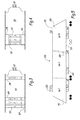
Figure 1 is a side view of a railway traction vehicle according to the present invention; -
Figure 2 is a perspective top view of the roof of the railway traction vehicle ofFigure 1 ; -
Figures 3 and 4 show two examples of possible fuel gas storage arrangements according to the present invention; and -
Figure 5 is a schematic side view of another railway traction vehicle according to the present invention. - With reference to
Figure 1 , there is shown arailway traction vehicle 100 according to the present invention. This railway traction vehicle is a regional passenger multiple unit. It has aroof 101 and afloor 103. It includes a first and asecond car transition zone 106. Eachcar traction bogie 108 and atrailer bogie 109. Thebogies axles 110. - The multiple unit's traction power is provided by two
fuel cells 112, one on eachcar fuel cells 112 operate by converting hydrogen and oxygen into water and electricity. The generated electricity is buffered in batteries (not shown) and then provided toelectric traction motors 114 located in thetraction bogies 108. -
Railway traction vehicle 100 also includes one or moreelectrical converters 116 for DC or AC conversion of the electrical current. - Two fuel
gas storage assemblies 118 are arranged on the railway traction vehicle'sroof 101, one on eachcar Figure 1 , the fuel gas stored in the fuelgas storage assemblies 118 is hydrogen. However, other fuel gases may also be used, such as liquefied petroleum gas or natural gas. - Hydrogen is delivered to a
fuel cell 112 from its associated fuelgas storage assembly 118 via a fuelgas delivery network 120. - Reference is now made to
Figure 2 , which provides further detail of the fuelgas storage assemblies 118. Each fuelgas storage assembly 118 comprises a predetermined number of fuelgas storage modules 122, a plurality of identical fuel gas storage module receivingdevices 124 and, for eachreceiving device 124, an identicalfuel gas coupling 126. - Preferably, the fuel
gas storage modules 122 all have a standard configuration and/or adapted dimensions in order to optimize the energy storage and weight balance for traction purposes. Accordingly, the fuelgas storage modules 122 are interchangeable. - The fuel
gas storage modules 122 can either be placed in a transversal or longitudinal position. Preferably, the fuelgas storage modules 122 all are high pressure vessels in a range of 20 MPa to 120 MPa. Preferably, a standard pressure of 35 MPa or 70 MPa is chosen. Furthermore, the volumetric capacity of the fuelgas storage modules 122 and the gas pressure therein are designed such that onemodule 122 provides therailway traction vehicle 100 with enough fuel gas to travel a certain predetermined average distance, e.g. around 100 - 200 km. - In the present example, the
modules 122 are hydrogen gas cylinders. Eachhydrogen gas cylinder 122 has the same cut-off valve and connection port (not shown). The hydrogen is preferably stored in thecylinders 122 at a pressure of 35 or 70 MPa. To withstand the high pressure, thegas cylinders 122 are very sturdy and heavy. In contrast thereto, hydrogen is very light. Thus, most of the weight of a filledgas cylinder 122 comes from the cylinder itself and not from its contents. Typically, the weight of the hydrogen stored in one cylinder is around 5 kg whereas an empty cylinder weighs around 120 kg. - The
fuel gas couplings 126 all have the same configuration. The hydrogen gas cylinders' connection ports are connected to thefuel gas couplings 126. Thereby, thehydrogen gas cylinders 122 are connected to the fuelgas delivery network 120. More precisely, the fuelgas delivery network 120 includes a fuelgas collecting manifold 128. The manifold 128 is preferably a collecting pipe that runs along the side of the receivingdevices 124. Onefuel gas coupling 126 branches off themanifold 128 for each receivingdevice 124. - Each receiving
device 124 is identical to ensure the interchangeability of thehydrogen gas cylinders 122. The receivingdevices 124 may consist of troughs shaped into theroof 101, as shown inFigure 2 . Alternatively, the receivingdevices 124 may also consist of a support frame for supporting onehydrogen gas cylinder 122 as shown inFigures 3 and 4 . The support frames 124 may be individually arranged in a row, as shown inFigure 3 . They may also be grouped intosupport frame assemblies 130, as shown inFigure 4 . InFigure 4 , threehydrogen gas cylinders 122 and their support frames 124 are assembled together to oneassembly 130. - The support frames 124 or the
support frame assemblies 130 are connected to the railway traction vehicle'sroof 101 via a connectingarrangement 132. Preferably, the connectingarrangement 132 includes two parallel connectingrails 134. The support frames 124 or thesupport frame assemblies 130 are located between the two connectingrails 134. They are connected to the connectingrails 134 viaouter segments 136. - The connecting
rails 134 may be fastening rails that fixedly fasten the support frames 124 or thesupport frame assemblies 130 to the railway traction vehicle'sroof 101. Alternatively, the connectingrails 134 may be guiding rails in which the support frames 124 or thesupport frame assemblies 130 are displaceably guided. -
Figure 5 shows asecond embodiment 200 of a railway traction vehicle according to the invention. This railway traction vehicle has a number N ofcars 202, where N is a natural number between 1 and 3. In this example, the fuelgas storage modules 222 are not only arranged on theroof 201 but also below thefloor 203 of therailway traction vehicle 200. More precisely, there is a first number n1 of fuelgas storage modules 222 distributed essentially over the entire length of the railway traction vehicle'sroof 201, a second number n2 of fuelgas storage modules 222 arranged below the floor of the first car, a third number n3 of fuelgas storage modules 222 arranged below the floor of the second car, and an xth number nx of fuelgas storage modules 222 arranged below the floor of the Nth car, where n1, n2, n3 and nx are natural numbers. - Preferably, there may be provided a fuel
gas connection line 205 allowing fuel gas to flow between the fuelgas storage modules 222 below thefloor 203 and the fuelgas storage modules 222 on theroof 201. - A typical application of the inventive modular
fuel gas tank 118 is as follows. When producing a new regional passengermultiple unit gas storage modules 122 to be fitted on the multiple unit is chosen as a function of the amount of fuel gas that is needed by therailway traction vehicle - Then, the chosen number of fuel
gas storage modules 122 is distributed over themultiple unit axles 110 is optimised. Thanks to the standardised configuration according to the invention, the distribution of themodules 122 can be easily adjusted, namely by simply switching themodules 122 from onereceiving device 124 to another receivingdevice 124. - Furthermore, if for example a
multiple unit gas storage modules 122 on the multiple unit can be easily reduced to fit the new railway line, thus reducing the multiple unit's weight and fuel consumption on the new railway line. This is in contrast to prior art fuel gas driven multiple units where their heavy high pressure fuel gas tank is fixedly installed and has a fixed size, meaning that such a prior art multiple unit will waste a lot of fuel on a short railway line for propelling the unneeded capacity of the fuel gas tank.
Claims (10)
- A railway traction vehicle (100) comprising:- a plurality of axles (110);- a power unit (112) adapted to generate at least a part of the vehicle's traction power using fuel gas;- a fuel gas storage assembly (118) adapted to provide fuel gas to the power unit (112) and including a predetermined number of fuel gas storage modules (122); and- a fuel gas delivery network (120) for delivering fuel gas from the fuel gas storage assembly (118) to the power unit (112),characterised in that:• the fuel gas storage assembly (118) comprises:- a plurality of identical fuel gas storage module receiving devices (124), each receiving device (124) being adapted to receive one fuel gas storage module (122); and- for each of said receiving devices (124), an identical fuel gas coupling (126) for coupling a fuel gas storage module (122) received in the receiving device (124) with said fuel gas delivery network (120),• said fuel gas storage modules (122):- share a standardised configuration such that each of them can be received in any of said receiving devices (124) and coupled to the corresponding fuel gas coupling (126), and- are distributed over said fuel gas storage module receiving devices (124) such that the load on the railway traction vehicle's axles (110) is optimised, and• said predetermined number of fuel gas storage modules (122) is adapted to the amount of fuel gas needed by the railway traction vehicle (100) to operate on a predetermined railway line.
- The railway traction vehicle (100) of claim 1, wherein the fuel gas delivery network (120) includes a fuel gas collecting manifold (128), each fuel gas coupling (126) being connected to the manifold.
- The railway traction vehicle (100) of any one of the previous claims, further comprising a fastening arrangement (132), preferably including two parallel fastening rails (134), fixedly fastening the receiving devices (124) to the railway traction vehicle (100).
- The railway traction vehicle (100) of claim 1 or 2, further comprising a guiding arrangement (132), preferably including two parallel guide rails (134), in which the receiving devices (124) are displaceably guided.
- The railway traction vehicle (100) of any one of the previous claims, wherein each receiving device is a support frame (124) for supporting one fuel gas storage module (122).
- The railway traction vehicle (100) of claim 5, wherein the support frames (124) are grouped into one or more support frame assemblies (130).
- The railway traction vehicle (100) of any one of the previous claims, wherein the fuel gas storage assembly (118) is arranged below the floor (103) and/or on the roof (101) of the railway traction vehicle (100).
- The railway traction vehicle (100) of any one of the previous claims, wherein each fuel gas storage module (122) consists of a high pressure vessel, preferably a gas cylinder, and most preferably a hydrogen gas cylinder.
- The railway traction vehicle (100) of any one of the previous claims, wherein the power unit (112) is a fuel cell.
- The railway traction vehicle (100) of any one of the previous claims, wherein the railway traction vehicle (100) is a regional passenger multiple unit.
Priority Applications (4)
| Application Number | Priority Date | Filing Date | Title |
|---|---|---|---|
| PL15305522.3T PL3078561T5 (en) | 2015-04-09 | 2015-04-09 | A railway traction vehicle with a modular fuel gas tank |
| DK15305522.3T DK3078561T4 (en) | 2015-04-09 | 2015-04-09 | Railway traction vehicle with a modular fuel gas tank |
| EP15305522.3A EP3078561B2 (en) | 2015-04-09 | 2015-04-09 | A railway traction vehicle with a modular fuel gas tank |
| US15/094,837 US10563629B2 (en) | 2015-04-09 | 2016-04-08 | Railway traction vehicle with a modular fuel gas tank |
Applications Claiming Priority (1)
| Application Number | Priority Date | Filing Date | Title |
|---|---|---|---|
| EP15305522.3A EP3078561B2 (en) | 2015-04-09 | 2015-04-09 | A railway traction vehicle with a modular fuel gas tank |
Publications (3)
| Publication Number | Publication Date |
|---|---|
| EP3078561A1 true EP3078561A1 (en) | 2016-10-12 |
| EP3078561B1 EP3078561B1 (en) | 2019-06-19 |
| EP3078561B2 EP3078561B2 (en) | 2022-11-09 |
Family
ID=52824200
Family Applications (1)
| Application Number | Title | Priority Date | Filing Date |
|---|---|---|---|
| EP15305522.3A Active EP3078561B2 (en) | 2015-04-09 | 2015-04-09 | A railway traction vehicle with a modular fuel gas tank |
Country Status (4)
| Country | Link |
|---|---|
| US (1) | US10563629B2 (en) |
| EP (1) | EP3078561B2 (en) |
| DK (1) | DK3078561T4 (en) |
| PL (1) | PL3078561T5 (en) |
Cited By (2)
| Publication number | Priority date | Publication date | Assignee | Title |
|---|---|---|---|---|
| EP4328108A1 (en) | 2022-08-23 | 2024-02-28 | Stadler Rail AG | Rail vehicle comprising a power pack with a fuel cell and a fuel tank |
| EP4335716A1 (en) * | 2022-09-09 | 2024-03-13 | Siemens Mobility GmbH | Railway vehicle |
Families Citing this family (5)
| Publication number | Priority date | Publication date | Assignee | Title |
|---|---|---|---|---|
| WO2016082651A1 (en) * | 2014-11-27 | 2016-06-02 | 中车青岛四方机车车辆股份有限公司 | Conversion circuit for implementing recoupling of random end of train |
| WO2017091579A1 (en) * | 2015-11-23 | 2017-06-01 | Optifuel Systems, LLC | Locomotive on-board storage and delivery of gaseous fuel |
| EP3802165B1 (en) * | 2018-07-18 | 2023-10-11 | Siemens Mobility GmbH | Vehicle and operating method for a vehicle |
| DE102018211989A1 (en) * | 2018-07-18 | 2020-01-23 | Siemens Mobility GmbH | Vehicle and operating method for a vehicle |
| CN115140104A (en) * | 2022-08-12 | 2022-10-04 | 中车大同电力机车有限公司 | Hydrogen fuel cell hybrid locomotive group |
Citations (4)
| Publication number | Priority date | Publication date | Assignee | Title |
|---|---|---|---|---|
| US7966945B1 (en) * | 2008-08-05 | 2011-06-28 | Bnsf Railway Company | Isolation and support structures for hydrogen hybrid locomotives and hydrogen hybrid locomotives using the same |
| EP2423067A1 (en) | 2010-08-26 | 2012-02-29 | ALSTOM Transport SA | Rail vehicle, drive unit for a rail vehicle and method for operating a rail vehicle |
| WO2014126480A1 (en) | 2013-02-12 | 2014-08-21 | Maintech As | Device for energy supply of trains |
| EP2783938A1 (en) * | 2013-03-29 | 2014-10-01 | ALSTOM Transport SA | On board fuel storage and supply in a rail vehicle |
Family Cites Families (24)
| Publication number | Priority date | Publication date | Assignee | Title |
|---|---|---|---|---|
| US4162796A (en) † | 1978-03-02 | 1979-07-31 | Nixdorff Krein Industries, Inc. | Tank mounting apparatus for tractors |
| DE4306178A1 (en) † | 1993-02-27 | 1994-09-01 | Goerlitz Waggonbau Gmbh | Method for mounting and dismounting pieces of equipment in the roof area of vehicles, in particular rail vehicles |
| DE29614089U1 (en) † | 1996-08-14 | 1996-09-26 | Deutsche Waggonbau Ag | Device attachment on the underside of a rail vehicle undercarriage, in particular a local transport rail vehicle |
| JP3651653B2 (en) † | 1999-02-03 | 2005-05-25 | 日産ディーゼル工業株式会社 | Body structure of a bus with a compressed natural gas engine |
| JP3627670B2 (en) † | 2001-05-16 | 2005-03-09 | 日産自動車株式会社 | High pressure gas container mounting structure |
| AU782189B2 (en) † | 2001-06-05 | 2005-07-07 | Doosan Industrial Vehicle Co., Ltd. | Fuel tank cradle device for forklift trucks |
| EP1340662A1 (en) † | 2002-03-01 | 2003-09-03 | Bombardier Transportation (Technology) Germany GmbH | Undercar assembly for a railcar |
| CA2495711C (en) † | 2004-02-03 | 2010-01-05 | Dynetek Industries Ltd. | Composite impact assembly |
| WO2006073192A1 (en) † | 2005-01-07 | 2006-07-13 | Toyota Jidosha Kabushiki Kaisha | Gaseous fuel tank loaded vehicle |
| US8596682B2 (en) † | 2009-05-29 | 2013-12-03 | Paccar Inc | Vehicle load mounting systems and methods of securing loads |
| JP5563851B2 (en) * | 2010-03-05 | 2014-07-30 | 株式会社東芝 | Hybrid locomotive |
| CN103118920B (en) † | 2010-09-20 | 2016-05-11 | 庞巴迪运输有限公司 | For compartment and the manufacture method thereof of rail vehicle |
| US20120085260A1 (en) † | 2010-10-07 | 2012-04-12 | Nichini Paul | Rail system fuel tender |
| DE102012206663A1 (en) † | 2012-04-23 | 2013-10-24 | Siemens Aktiengesellschaft | Structure-stable arrangement and method for forming a structure-stable arrangement. |
| US20140069972A1 (en) † | 2012-09-10 | 2014-03-13 | Alternative Fuel Containers, LLC (KSR Technologies Co.) | Method and apparatus for mounting cng/ang tanks to heavy trucks |
| US9637141B2 (en) † | 2012-12-03 | 2017-05-02 | Electro-Motive Diesel, Inc. | Locomotive system |
| DE102012223813A1 (en) † | 2012-12-19 | 2014-06-26 | Siemens Aktiengesellschaft | Roof of a rail vehicle |
| DE102013200628A1 (en) † | 2013-01-17 | 2014-07-17 | Siemens Aktiengesellschaft | Attachment of a rail vehicle component on a car body roof of a rail vehicle car body |
| EP2951043A4 (en) † | 2013-02-01 | 2017-02-15 | Agility Fuel Systems, Inc. | Modular fuel storage system |
| US9200554B2 (en) † | 2013-03-15 | 2015-12-01 | Clean Train Propulsion | Hybrid systems for locomotives |
| US20140318410A1 (en) * | 2013-04-26 | 2014-10-30 | Progress Rail Services Corporation | Locomotive with variable power modules |
| DE102013110637A1 (en) † | 2013-09-26 | 2015-03-26 | Sma Railway Technology Gmbh | Receiving and supporting system for converters for rail vehicles |
| US20160167677A1 (en) * | 2014-12-11 | 2016-06-16 | US Railcar Company, LLC | Railcar having natural gas engine |
| WO2017091579A1 (en) * | 2015-11-23 | 2017-06-01 | Optifuel Systems, LLC | Locomotive on-board storage and delivery of gaseous fuel |
-
2015
- 2015-04-09 EP EP15305522.3A patent/EP3078561B2/en active Active
- 2015-04-09 PL PL15305522.3T patent/PL3078561T5/en unknown
- 2015-04-09 DK DK15305522.3T patent/DK3078561T4/en active
-
2016
- 2016-04-08 US US15/094,837 patent/US10563629B2/en active Active
Patent Citations (4)
| Publication number | Priority date | Publication date | Assignee | Title |
|---|---|---|---|---|
| US7966945B1 (en) * | 2008-08-05 | 2011-06-28 | Bnsf Railway Company | Isolation and support structures for hydrogen hybrid locomotives and hydrogen hybrid locomotives using the same |
| EP2423067A1 (en) | 2010-08-26 | 2012-02-29 | ALSTOM Transport SA | Rail vehicle, drive unit for a rail vehicle and method for operating a rail vehicle |
| WO2014126480A1 (en) | 2013-02-12 | 2014-08-21 | Maintech As | Device for energy supply of trains |
| EP2783938A1 (en) * | 2013-03-29 | 2014-10-01 | ALSTOM Transport SA | On board fuel storage and supply in a rail vehicle |
Cited By (2)
| Publication number | Priority date | Publication date | Assignee | Title |
|---|---|---|---|---|
| EP4328108A1 (en) | 2022-08-23 | 2024-02-28 | Stadler Rail AG | Rail vehicle comprising a power pack with a fuel cell and a fuel tank |
| EP4335716A1 (en) * | 2022-09-09 | 2024-03-13 | Siemens Mobility GmbH | Railway vehicle |
Also Published As
| Publication number | Publication date |
|---|---|
| EP3078561B2 (en) | 2022-11-09 |
| PL3078561T5 (en) | 2023-03-13 |
| EP3078561B1 (en) | 2019-06-19 |
| DK3078561T3 (en) | 2020-04-27 |
| DK3078561T4 (en) | 2022-12-12 |
| PL3078561T3 (en) | 2020-01-31 |
| US20160297451A1 (en) | 2016-10-13 |
| US10563629B2 (en) | 2020-02-18 |
Similar Documents
| Publication | Publication Date | Title |
|---|---|---|
| US10563629B2 (en) | Railway traction vehicle with a modular fuel gas tank | |
| CN110958956B (en) | Device for storing compressed fluid | |
| CN102398531A (en) | Rail car with onboard electric components for rail cars mounted thereon and train of rail cars | |
| CN106457991B (en) | Vehicle with energy accumulator | |
| EP2428448B1 (en) | Method for providing energy and energy supply unit | |
| US20120085260A1 (en) | Rail system fuel tender | |
| US9073556B2 (en) | Fuel distribution system for multi-locomotive consist | |
| CN102019840A (en) | Vehicle having energy accumulator area | |
| EP2335993A1 (en) | High capacity passenger train set | |
| US8413589B2 (en) | Container-based locomotive power source | |
| DE102016003532A1 (en) | Energy transfer device for a transport vehicle and method for the exchange of electrical energy between a transport vehicle and transported by this vehicles | |
| Hirose et al. | Development of catenary and storage battery hybrid train system | |
| CN102975725B (en) | Power decentralized and the motor train unit of Relatively centralized | |
| CN113371003A (en) | Railway maintenance operation vehicle for hydrogen energy power contact network | |
| EP1572515A2 (en) | Power supply means for multiple-unit trains | |
| CN201423931Y (en) | High power centralized auxiliary power supply system for high speed motor train unit | |
| CN105799719A (en) | Novel internal combustion electric transmission rail vehicle | |
| AU2016227774A1 (en) | Rail vehicle, method for driving a rail vehicle and method for producing a rail vehicle | |
| RU2650286C2 (en) | Method of hybrid diesel-contact shunting locomotive operation with energy accumulators and shunting locomotive | |
| Andrzejewski et al. | The latest technical solutions in rail vehicles drives | |
| CN101797921A (en) | Heavy-duty rail motor car | |
| ES2950729T3 (en) | Arrangement for driving a locomotive with different power supply systems | |
| CN201597590U (en) | Heavy type railcar | |
| CN113401154A (en) | Locomotive unit, freight locomotive and freight locomotive management method | |
| US20230415598A1 (en) | Means of transportation for electric vehicles |
Legal Events
| Date | Code | Title | Description |
|---|---|---|---|
| PUAI | Public reference made under article 153(3) epc to a published international application that has entered the european phase |
Free format text: ORIGINAL CODE: 0009012 |
|
| 17P | Request for examination filed |
Effective date: 20160224 |
|
| AK | Designated contracting states |
Kind code of ref document: A1 Designated state(s): AL AT BE BG CH CY CZ DE DK EE ES FI FR GB GR HR HU IE IS IT LI LT LU LV MC MK MT NL NO PL PT RO RS SE SI SK SM TR |
|
| AX | Request for extension of the european patent |
Extension state: BA ME |
|
| GRAP | Despatch of communication of intention to grant a patent |
Free format text: ORIGINAL CODE: EPIDOSNIGR1 |
|
| STAA | Information on the status of an ep patent application or granted ep patent |
Free format text: STATUS: GRANT OF PATENT IS INTENDED |
|
| RIC1 | Information provided on ipc code assigned before grant |
Ipc: B61C 5/00 20060101AFI20181022BHEP |
|
| INTG | Intention to grant announced |
Effective date: 20181205 |
|
| GRAS | Grant fee paid |
Free format text: ORIGINAL CODE: EPIDOSNIGR3 |
|
| GRAJ | Information related to disapproval of communication of intention to grant by the applicant or resumption of examination proceedings by the epo deleted |
Free format text: ORIGINAL CODE: EPIDOSDIGR1 |
|
| GRAL | Information related to payment of fee for publishing/printing deleted |
Free format text: ORIGINAL CODE: EPIDOSDIGR3 |
|
| STAA | Information on the status of an ep patent application or granted ep patent |
Free format text: STATUS: REQUEST FOR EXAMINATION WAS MADE |
|
| INTC | Intention to grant announced (deleted) | ||
| GRAR | Information related to intention to grant a patent recorded |
Free format text: ORIGINAL CODE: EPIDOSNIGR71 |
|
| STAA | Information on the status of an ep patent application or granted ep patent |
Free format text: STATUS: GRANT OF PATENT IS INTENDED |
|
| GRAA | (expected) grant |
Free format text: ORIGINAL CODE: 0009210 |
|
| STAA | Information on the status of an ep patent application or granted ep patent |
Free format text: STATUS: THE PATENT HAS BEEN GRANTED |
|
| AK | Designated contracting states |
Kind code of ref document: B1 Designated state(s): AL AT BE BG CH CY CZ DE DK EE ES FI FR GB GR HR HU IE IS IT LI LT LU LV MC MK MT NL NO PL PT RO RS SE SI SK SM TR |
|
| INTG | Intention to grant announced |
Effective date: 20190513 |
|
| REG | Reference to a national code |
Ref country code: GB Ref legal event code: FG4D |
|
| REG | Reference to a national code |
Ref country code: CH Ref legal event code: EP |
|
| REG | Reference to a national code |
Ref country code: IE Ref legal event code: FG4D |
|
| REG | Reference to a national code |
Ref country code: AT Ref legal event code: REF Ref document number: 1145115 Country of ref document: AT Kind code of ref document: T Effective date: 20190715 |
|
| REG | Reference to a national code |
Ref country code: DE Ref legal event code: R096 Ref document number: 602015032181 Country of ref document: DE |
|
| REG | Reference to a national code |
Ref country code: NL Ref legal event code: FP |
|
| PG25 | Lapsed in a contracting state [announced via postgrant information from national office to epo] |
Ref country code: LT Free format text: LAPSE BECAUSE OF FAILURE TO SUBMIT A TRANSLATION OF THE DESCRIPTION OR TO PAY THE FEE WITHIN THE PRESCRIBED TIME-LIMIT Effective date: 20190619 Ref country code: FI Free format text: LAPSE BECAUSE OF FAILURE TO SUBMIT A TRANSLATION OF THE DESCRIPTION OR TO PAY THE FEE WITHIN THE PRESCRIBED TIME-LIMIT Effective date: 20190619 Ref country code: NO Free format text: LAPSE BECAUSE OF FAILURE TO SUBMIT A TRANSLATION OF THE DESCRIPTION OR TO PAY THE FEE WITHIN THE PRESCRIBED TIME-LIMIT Effective date: 20190919 Ref country code: HR Free format text: LAPSE BECAUSE OF FAILURE TO SUBMIT A TRANSLATION OF THE DESCRIPTION OR TO PAY THE FEE WITHIN THE PRESCRIBED TIME-LIMIT Effective date: 20190619 Ref country code: SE Free format text: LAPSE BECAUSE OF FAILURE TO SUBMIT A TRANSLATION OF THE DESCRIPTION OR TO PAY THE FEE WITHIN THE PRESCRIBED TIME-LIMIT Effective date: 20190619 Ref country code: AL Free format text: LAPSE BECAUSE OF FAILURE TO SUBMIT A TRANSLATION OF THE DESCRIPTION OR TO PAY THE FEE WITHIN THE PRESCRIBED TIME-LIMIT Effective date: 20190619 |
|
| REG | Reference to a national code |
Ref country code: LT Ref legal event code: MG4D |
|
| PG25 | Lapsed in a contracting state [announced via postgrant information from national office to epo] |
Ref country code: RS Free format text: LAPSE BECAUSE OF FAILURE TO SUBMIT A TRANSLATION OF THE DESCRIPTION OR TO PAY THE FEE WITHIN THE PRESCRIBED TIME-LIMIT Effective date: 20190619 Ref country code: LV Free format text: LAPSE BECAUSE OF FAILURE TO SUBMIT A TRANSLATION OF THE DESCRIPTION OR TO PAY THE FEE WITHIN THE PRESCRIBED TIME-LIMIT Effective date: 20190619 Ref country code: BG Free format text: LAPSE BECAUSE OF FAILURE TO SUBMIT A TRANSLATION OF THE DESCRIPTION OR TO PAY THE FEE WITHIN THE PRESCRIBED TIME-LIMIT Effective date: 20190919 Ref country code: GR Free format text: LAPSE BECAUSE OF FAILURE TO SUBMIT A TRANSLATION OF THE DESCRIPTION OR TO PAY THE FEE WITHIN THE PRESCRIBED TIME-LIMIT Effective date: 20190920 |
|
| REG | Reference to a national code |
Ref country code: AT Ref legal event code: MK05 Ref document number: 1145115 Country of ref document: AT Kind code of ref document: T Effective date: 20190619 |
|
| PG25 | Lapsed in a contracting state [announced via postgrant information from national office to epo] |
Ref country code: AT Free format text: LAPSE BECAUSE OF FAILURE TO SUBMIT A TRANSLATION OF THE DESCRIPTION OR TO PAY THE FEE WITHIN THE PRESCRIBED TIME-LIMIT Effective date: 20190619 Ref country code: SK Free format text: LAPSE BECAUSE OF FAILURE TO SUBMIT A TRANSLATION OF THE DESCRIPTION OR TO PAY THE FEE WITHIN THE PRESCRIBED TIME-LIMIT Effective date: 20190619 Ref country code: RO Free format text: LAPSE BECAUSE OF FAILURE TO SUBMIT A TRANSLATION OF THE DESCRIPTION OR TO PAY THE FEE WITHIN THE PRESCRIBED TIME-LIMIT Effective date: 20190619 Ref country code: CZ Free format text: LAPSE BECAUSE OF FAILURE TO SUBMIT A TRANSLATION OF THE DESCRIPTION OR TO PAY THE FEE WITHIN THE PRESCRIBED TIME-LIMIT Effective date: 20190619 Ref country code: PT Free format text: LAPSE BECAUSE OF FAILURE TO SUBMIT A TRANSLATION OF THE DESCRIPTION OR TO PAY THE FEE WITHIN THE PRESCRIBED TIME-LIMIT Effective date: 20191021 Ref country code: EE Free format text: LAPSE BECAUSE OF FAILURE TO SUBMIT A TRANSLATION OF THE DESCRIPTION OR TO PAY THE FEE WITHIN THE PRESCRIBED TIME-LIMIT Effective date: 20190619 |
|
| PG25 | Lapsed in a contracting state [announced via postgrant information from national office to epo] |
Ref country code: ES Free format text: LAPSE BECAUSE OF FAILURE TO SUBMIT A TRANSLATION OF THE DESCRIPTION OR TO PAY THE FEE WITHIN THE PRESCRIBED TIME-LIMIT Effective date: 20190619 Ref country code: IS Free format text: LAPSE BECAUSE OF FAILURE TO SUBMIT A TRANSLATION OF THE DESCRIPTION OR TO PAY THE FEE WITHIN THE PRESCRIBED TIME-LIMIT Effective date: 20191019 Ref country code: SM Free format text: LAPSE BECAUSE OF FAILURE TO SUBMIT A TRANSLATION OF THE DESCRIPTION OR TO PAY THE FEE WITHIN THE PRESCRIBED TIME-LIMIT Effective date: 20190619 |
|
| REG | Reference to a national code |
Ref country code: DE Ref legal event code: R026 Ref document number: 602015032181 Country of ref document: DE |
|
| PLBI | Opposition filed |
Free format text: ORIGINAL CODE: 0009260 |
|
| PG25 | Lapsed in a contracting state [announced via postgrant information from national office to epo] |
Ref country code: TR Free format text: LAPSE BECAUSE OF FAILURE TO SUBMIT A TRANSLATION OF THE DESCRIPTION OR TO PAY THE FEE WITHIN THE PRESCRIBED TIME-LIMIT Effective date: 20190619 |
|
| 26 | Opposition filed |
Opponent name: STADLER RAIL AG Effective date: 20200317 |
|
| REG | Reference to a national code |
Ref country code: DK Ref legal event code: T3 Effective date: 20200423 |
|
| PG25 | Lapsed in a contracting state [announced via postgrant information from national office to epo] |
Ref country code: IS Free format text: LAPSE BECAUSE OF FAILURE TO SUBMIT A TRANSLATION OF THE DESCRIPTION OR TO PAY THE FEE WITHIN THE PRESCRIBED TIME-LIMIT Effective date: 20200224 |
|
| PLAX | Notice of opposition and request to file observation + time limit sent |
Free format text: ORIGINAL CODE: EPIDOSNOBS2 |
|
| PG2D | Information on lapse in contracting state deleted |
Ref country code: IS |
|
| PG25 | Lapsed in a contracting state [announced via postgrant information from national office to epo] |
Ref country code: SI Free format text: LAPSE BECAUSE OF FAILURE TO SUBMIT A TRANSLATION OF THE DESCRIPTION OR TO PAY THE FEE WITHIN THE PRESCRIBED TIME-LIMIT Effective date: 20190619 |
|
| PLBB | Reply of patent proprietor to notice(s) of opposition received |
Free format text: ORIGINAL CODE: EPIDOSNOBS3 |
|
| PG25 | Lapsed in a contracting state [announced via postgrant information from national office to epo] |
Ref country code: MC Free format text: LAPSE BECAUSE OF FAILURE TO SUBMIT A TRANSLATION OF THE DESCRIPTION OR TO PAY THE FEE WITHIN THE PRESCRIBED TIME-LIMIT Effective date: 20190619 |
|
| REG | Reference to a national code |
Ref country code: CH Ref legal event code: PL |
|
| PG25 | Lapsed in a contracting state [announced via postgrant information from national office to epo] |
Ref country code: CH Free format text: LAPSE BECAUSE OF NON-PAYMENT OF DUE FEES Effective date: 20200430 Ref country code: LI Free format text: LAPSE BECAUSE OF NON-PAYMENT OF DUE FEES Effective date: 20200430 Ref country code: LU Free format text: LAPSE BECAUSE OF NON-PAYMENT OF DUE FEES Effective date: 20200409 |
|
| REG | Reference to a national code |
Ref country code: BE Ref legal event code: MM Effective date: 20200430 |
|
| PG25 | Lapsed in a contracting state [announced via postgrant information from national office to epo] |
Ref country code: BE Free format text: LAPSE BECAUSE OF NON-PAYMENT OF DUE FEES Effective date: 20200430 |
|
| GBPC | Gb: european patent ceased through non-payment of renewal fee |
Effective date: 20200409 |
|
| PG25 | Lapsed in a contracting state [announced via postgrant information from national office to epo] |
Ref country code: GB Free format text: LAPSE BECAUSE OF NON-PAYMENT OF DUE FEES Effective date: 20200409 Ref country code: IE Free format text: LAPSE BECAUSE OF NON-PAYMENT OF DUE FEES Effective date: 20200409 |
|
| PG25 | Lapsed in a contracting state [announced via postgrant information from national office to epo] |
Ref country code: MT Free format text: LAPSE BECAUSE OF FAILURE TO SUBMIT A TRANSLATION OF THE DESCRIPTION OR TO PAY THE FEE WITHIN THE PRESCRIBED TIME-LIMIT Effective date: 20190619 Ref country code: CY Free format text: LAPSE BECAUSE OF FAILURE TO SUBMIT A TRANSLATION OF THE DESCRIPTION OR TO PAY THE FEE WITHIN THE PRESCRIBED TIME-LIMIT Effective date: 20190619 |
|
| PG25 | Lapsed in a contracting state [announced via postgrant information from national office to epo] |
Ref country code: MK Free format text: LAPSE BECAUSE OF FAILURE TO SUBMIT A TRANSLATION OF THE DESCRIPTION OR TO PAY THE FEE WITHIN THE PRESCRIBED TIME-LIMIT Effective date: 20190619 |
|
| PUAH | Patent maintained in amended form |
Free format text: ORIGINAL CODE: 0009272 |
|
| STAA | Information on the status of an ep patent application or granted ep patent |
Free format text: STATUS: PATENT MAINTAINED AS AMENDED |
|
| 27A | Patent maintained in amended form |
Effective date: 20221109 |
|
| AK | Designated contracting states |
Kind code of ref document: B2 Designated state(s): AL AT BE BG CH CY CZ DE DK EE ES FI FR GB GR HR HU IE IS IT LI LT LU LV MC MK MT NL NO PL PT RO RS SE SI SK SM TR |
|
| REG | Reference to a national code |
Ref country code: DE Ref legal event code: R102 Ref document number: 602015032181 Country of ref document: DE |
|
| REG | Reference to a national code |
Ref country code: DK Ref legal event code: T4 Effective date: 20221207 |
|
| REG | Reference to a national code |
Ref country code: NL Ref legal event code: FP |
|
| PGFP | Annual fee paid to national office [announced via postgrant information from national office to epo] |
Ref country code: PL Payment date: 20230330 Year of fee payment: 9 |
|
| PGFP | Annual fee paid to national office [announced via postgrant information from national office to epo] |
Ref country code: NL Payment date: 20230419 Year of fee payment: 9 |
|
| PGFP | Annual fee paid to national office [announced via postgrant information from national office to epo] |
Ref country code: IT Payment date: 20230426 Year of fee payment: 9 Ref country code: FR Payment date: 20230424 Year of fee payment: 9 Ref country code: DK Payment date: 20230421 Year of fee payment: 9 Ref country code: DE Payment date: 20230420 Year of fee payment: 9 |
|
| P01 | Opt-out of the competence of the unified patent court (upc) registered |
Effective date: 20230823 |