EP3078542A1 - Seat backrest for a motor vehicle - Google Patents
Seat backrest for a motor vehicle Download PDFInfo
- Publication number
- EP3078542A1 EP3078542A1 EP15163285.8A EP15163285A EP3078542A1 EP 3078542 A1 EP3078542 A1 EP 3078542A1 EP 15163285 A EP15163285 A EP 15163285A EP 3078542 A1 EP3078542 A1 EP 3078542A1
- Authority
- EP
- European Patent Office
- Prior art keywords
- coupling portion
- plate
- seat backrest
- brackets
- rear plate
- Prior art date
- Legal status (The legal status is an assumption and is not a legal conclusion. Google has not performed a legal analysis and makes no representation as to the accuracy of the status listed.)
- Granted
Links
Images
Classifications
-
- B—PERFORMING OPERATIONS; TRANSPORTING
- B60—VEHICLES IN GENERAL
- B60N—SEATS SPECIALLY ADAPTED FOR VEHICLES; VEHICLE PASSENGER ACCOMMODATION NOT OTHERWISE PROVIDED FOR
- B60N2/00—Seats specially adapted for vehicles; Arrangement or mounting of seats in vehicles
- B60N2/68—Seat frames
- B60N2/682—Joining means
-
- B—PERFORMING OPERATIONS; TRANSPORTING
- B60—VEHICLES IN GENERAL
- B60N—SEATS SPECIALLY ADAPTED FOR VEHICLES; VEHICLE PASSENGER ACCOMMODATION NOT OTHERWISE PROVIDED FOR
- B60N2/00—Seats specially adapted for vehicles; Arrangement or mounting of seats in vehicles
- B60N2/58—Seat coverings
- B60N2/5816—Seat coverings attachments thereof
- B60N2/5841—Seat coverings attachments thereof by clamping means
-
- B—PERFORMING OPERATIONS; TRANSPORTING
- B60—VEHICLES IN GENERAL
- B60N—SEATS SPECIALLY ADAPTED FOR VEHICLES; VEHICLE PASSENGER ACCOMMODATION NOT OTHERWISE PROVIDED FOR
- B60N2/00—Seats specially adapted for vehicles; Arrangement or mounting of seats in vehicles
- B60N2/68—Seat frames
- B60N2/686—Panel like structures
Definitions
- the present invention relates to a seat backrest.
- the present invention relates to a backrest of a rear seat of a motor vehicle.
- rear seats of motor vehicles define the front surface of the luggage compartment and must therefore be sufficiently robust to withstand impact forces of the luggage against said surface in case of sudden braking or even in the event of an accident.
- rear seats have a rear structure, which supports a padding, which, in turn, is covered by a cover.
- Said structure is normally made of a metal material and comprises a tubular element and a substantially vertical plate having a peripheral groove, to which the edge of the cover is attached.
- the tubular element extends in a circular fashion on the front surface of the plate and is foxed to said plate.
- the metal plate is fixed to the tubular element by means of rivets.
- a finishing panel made of a plastic material covers the rear surface of the metal plate, so as to cover the rivets and create a better look of the front surface of the luggage compartment.
- the plate of the rear structure is made of a plastic or composite material - and not of a metal material - in order to reduce the weight of the backrest.
- the cover forms a casing that completely wraps the padding and the structure of the backrest and can be opened, for example through a zip, in order to be then removed from the remaining part of the backrest and, for example, be washed by the user.
- the fabric of the casing defines the front surface of the luggage compartment, thus ensuring a definitely good look.
- this solution is relatively expensive, which makes it not suited for medium-low range cars.
- the object of the present invention is to provide a seat backrest, which overcomes the drawback described above in a simple and cost-effective manner and can use a rear plate made of a plastic material, preferably with a shape and sizes that are the same as those of known solutions.
- a seat backrest as claimed in claim 1.
- number 1 indicates, as a whole, a seat backrest (partially shown), mounted in a last row of seats in a motor vehicle.
- the backrest 1 comprises a rear structure 2 and a padding 3, which is supported by the structure in a known manner - not described in detail - and is made, for example, of a foam material.
- the backrest 1 comprises, furthermore, a cover 4, which is made, for example, of fabric and covers the front and sides of the padding 3.
- the structure 2 comprises a plate 9, which is made of a plastic material or of a composite material comprising a plastic material.
- This composite material for example, is defined by a fibre-reinforced plastic material.
- the plate 9 comprises a cell-like structure (not shown), for example with closed cells.
- the plate 9 can be a multi-layer plate.
- the plate 9 has a peripheral edge 12 covered by the cover 4 and comprises an intermediate portion 13 having a rear surface ( figure 2 ), which directly delimits (namely, without any additional cover) a luggage compartment (not shown) of the motor vehicle.
- the plate 9 comprises, furthermore, a coupling portion 15, which is arranged along the edge 12 and is fixed to an end 16 of the cover 4, so as to keep the cover 4 itself in a fixed position, where it adheres to the padding 3.
- the coupling portion 15 has a U-shaped cross section, so as to define a channel 17, which is substantially parallel to the edge 12 and houses the end 16.
- the end 16 remains clamped in a fixed position between the coupling portion 15 and an insert 18, which is also inserted into the cavity 17.
- the coupling portion 15 is made up of: a wall 19, which is joined to the edge 12; a wall 20, which is substantially parallel to the wall 19 and is joined to the portion 13; and a curved wall 21, which joins the walls 19 and 20 to one another and defines the bottom of the channel 17.
- the coupling portion 15 is provided with a plurality of holding seats or holes to fix, for example through pressure, corresponding buttons or pins that are fixed to the end 16 of the cover 4.
- the plate 9 has a front surface 22, on which a stiffening frame 25 is arranged.
- the frame 25 is part of the structure 2 and is at least partially housed in the padding 3.
- the frame 25 is preferably made of a metal material and consists of one or more elements, which are oblong and extend along an axis 26 that is substantially parallel to the plate 9.
- these oblong elements form a ring frame, with the axis 26 that is substantially parallel to the edge 12.
- Each oblong element is preferably defined by a relative tube, whose cross section has, for example, a rectangular or square outer shape with rounded corners.
- the frame 25 is coupled to the plate 9 in a fixed position through a snap-on connecting device 30.
- an adhesive (not shown) is provided, so as to keep the frame 25 in a fixed position in addition to the action of the device 30.
- the device 30 comprises a plurality of elastically deformable appendages 36, which are carried by the plate 9, project from the plate 9 on the side of the surface 22, are located in fixed positions, and are spaced apart from one another in a direction that is parallel to the axis 26. As shown in figure 2 , the appendages 36 end with respective teeth or projections 37 facing the surface 22, so as to define a holding seat 38 engaged by the frame 25.
- the appendages 36 comprise respective walls 39, which are arranged next to an outer lateral surface 40 of the frame 25 and are elastically flexible.
- the free ends of the walls 39 define the teeth 37 and are shaped so as to form suitable bevels or outer fittings 41, which define the surface needed to obtain a parting of the teeth 37 and, therefore, to let the frame 25 into the seat 38, when the frame 25 is pushed towards the surface 22 while being mounted on the plate 9.
- the frame 25 is placed on the free ends of the appendages 36 without requiring a special placing equipment, since the appendages 36 themselves take care of centring the frame 25.
- the walls 39 elastically snap into their original position and, hence, the teeth 37 hook a front surface 42 of the frame 25, so as to prevent the latter from moving away from the surface 22.
- the frame 25 can be further fixed to the plate 9 by means of additional gluing spots or seams (not shown).
- the appendages 36 make up part of respective brackets 43, which are defined by pieces that are distinct from the plate 9 and are fixed to the latter before mounting the frame 25.
- the brackets 43 are preferably made of a metal material and comprise respective base portions 44, which are at least partially embedded in the plastic material of the plate 9.
- said plastic material is thermomelting and is heated as the base portions 44 ate pressed against the plate 9, so as to cause them to be partially embedded therein, which allows the brackets 43 to be fixed, once the plastic material is brought back to room temperature.
- the plate 9 is made of a thermoformable material and is subject to a thermoforming process, so as to cause it to assume a desired, not perfectly flat shape, before mounting the frame 25.
- the brackets 43 are arranged in the thermoforming mould (not shown) together with a flat blank to be thermoformed, so as to cause the portions 44 to be embedded in the plastic material during the thermoforming process.
- the brackets 43 comprise respective stiffening portions 45, which are frontally arranged in the are of the coupling portion 15, namely on the side of the surface 22.
- the cover 4 is kept stretched after having been fitted on the padding 3 and fixed to the coupling portion 15; due to the tension exerted by the cover 4 and to the relatively high deformability of the plate 9, the coupling portion 15 tends to bend forward, but the portions 45 counter this bending movement, as they are stiffer.
- the portions 45 rest against the wall 19, part of the curved wall 21 and the fillet joining the wall 19 to the edge 12.
- the portions 45 are partially embedded in the plastic material of the coupling portion 15.
- each arm 45 comprises: a curved portion 47, against which the curved portion 21 rests; a wall 48, which is arranged next to the entire wall 19; and an attachment portion 50, which connects the curved portion 21 to an intermediate portion of the wall 39.
- the base portions 44 comprise respective ends 51, which are arranged along the fillet joining the wall 20 to the portion 13, so as to also stiffen this area. At this fillet, the ends 51 are rounded, so as not have sharp corners.
- the plate 9 can be made of a plastic material, even if the coupling portion 15 becomes relatively flexible, since the brackets 43 have features that allow them to stiffen the coupling portion 15 itself.
- the solution suggested herein is relative simple, since the brackets 43 are also used to define the device 30 and do not interfere with the design, the size and the shape of the plate 9.
- this solution is relatively light, due to the material with which the plate 9 can be made.
- the features concerning the way in which the cover 4 is held in position and caused to be adherent remain the same, without having to change the method with which the cover 4 is fitted.
- the performances of the backrest 1 in terms of resistance to the impact of the luggage in case of sudden braking or possible accidents remain the same.
- the frame 25 is snap-mounted on the plate 9, without the need to use a special equipment to correctly position the frame 25 relative to the plate 9.
- the solution suggested herein does not force manufacturers to change the constructive features of the frame 25, which, therefore, can be identical to known traditional solutions.
- brackets 43 instead of having one single element, allows manufacturers to reduce the quantity of metal material used.
- brackets 43 could be different from the one described herein, but the one shown in the drawings is optimal in terms of compromise between stiffening of the coupling portion 15, on the one hand, and simplicity, compactness, weight and saving of metal material, on the other hand.
- brackets 43 can be fixed to the plate 9 in a different fashion from the one described above, for example by means of mechanical elements and/or through glue.
- the material of the brackets 43 despite having to be a relatively valuable material, so as to give to the coupling portion 15 a sufficient stiffness, could also be a non-metal material.
- the appendages 36 can have a different shape from the one shown herein, depending on the elasticity of the material chosen for the brackets 43 and depending on the cross section and the size of the elements forming the frame 25.
- brackets 43 that are fixed on the plate 9 could have no appendages 36 and only have the portions 45.
Landscapes
- Engineering & Computer Science (AREA)
- Aviation & Aerospace Engineering (AREA)
- Transportation (AREA)
- Mechanical Engineering (AREA)
- Chair Legs, Seat Parts, And Backrests (AREA)
Abstract
Description
- The present invention relates to a seat backrest. In particular the present invention relates to a backrest of a rear seat of a motor vehicle.
- As it is known, the rear seats of motor vehicles define the front surface of the luggage compartment and must therefore be sufficiently robust to withstand impact forces of the luggage against said surface in case of sudden braking or even in the event of an accident. For that purpose, rear seats have a rear structure, which supports a padding, which, in turn, is covered by a cover. Said structure is normally made of a metal material and comprises a tubular element and a substantially vertical plate having a peripheral groove, to which the edge of the cover is attached. The tubular element extends in a circular fashion on the front surface of the plate and is foxed to said plate.
- Normally, the metal plate is fixed to the tubular element by means of rivets. Generally, a finishing panel made of a plastic material covers the rear surface of the metal plate, so as to cover the rivets and create a better look of the front surface of the luggage compartment.
- In the solution described in patent
EP2487065B1 , which corresponds to the preamble of claim 1, the tubular element is snap-fixed to the metal plate, thus avoiding the use of rivets. - Furthermore, in patent
EP2487065B1 , the plate of the rear structure is made of a plastic or composite material - and not of a metal material - in order to reduce the weight of the backrest. - If you change the material of the plate, the solutions described above are not suited any longer for the procedure that is normally used to fit the cover on the padding. As a matter of fact, during this procedure, the edge of the cover is fixed to the peripheral groove of the metal plate, while the padding is being compressed; in this way, when the compression is released, the fabric of the cover is automatically stretched, thus substantially avoiding the formation of creases. A plastic material plate has a definitely smaller rigidity compared to one made of a metal material and, therefore, it deforms to a greater extent when the compression is released; due to this deformation, the residual tension of the cover is not sufficient to avoid creases or similar defects.
- In other solutions, the cover forms a casing that completely wraps the padding and the structure of the backrest and can be opened, for example through a zip, in order to be then removed from the remaining part of the backrest and, for example, be washed by the user. In this case, the fabric of the casing defines the front surface of the luggage compartment, thus ensuring a definitely good look. However, this solution is relatively expensive, which makes it not suited for medium-low range cars.
- The object of the present invention is to provide a seat backrest, which overcomes the drawback described above in a simple and cost-effective manner and can use a rear plate made of a plastic material, preferably with a shape and sizes that are the same as those of known solutions.
- According to the present invention, there is provided a seat backrest as claimed in claim 1.
- The present invention will be best understood upon perusal of the following detailed description of a preferred embodiment, which is provided by way of example and is not limiting, with reference to the accompanying drawings, in which:
-
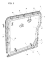
figure 1 is a perspective view showing, with parts removed for greater clarity, a preferred embodiment of the seat backrest according to the present invention; and -
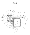
figure 2 is a cross section along the section plane indicated by line II-II offigure 1 and shows, on a larger scale, a detail of the backrest offigure 1 . - In
figure 1 , number 1 indicates, as a whole, a seat backrest (partially shown), mounted in a last row of seats in a motor vehicle. - The backrest 1 comprises a
rear structure 2 and apadding 3, which is supported by the structure in a known manner - not described in detail - and is made, for example, of a foam material. The backrest 1 comprises, furthermore, acover 4, which is made, for example, of fabric and covers the front and sides of thepadding 3. - The
structure 2 comprises aplate 9, which is made of a plastic material or of a composite material comprising a plastic material. This composite material, for example, is defined by a fibre-reinforced plastic material. Preferably, theplate 9 comprises a cell-like structure (not shown), for example with closed cells. As an alternative to or in combination with the cell-like structure, theplate 9 can be a multi-layer plate. - The
plate 9 has aperipheral edge 12 covered by thecover 4 and comprises anintermediate portion 13 having a rear surface (figure 2 ), which directly delimits (namely, without any additional cover) a luggage compartment (not shown) of the motor vehicle. - With reference to
figure 2 , theplate 9 comprises, furthermore, acoupling portion 15, which is arranged along theedge 12 and is fixed to anend 16 of thecover 4, so as to keep thecover 4 itself in a fixed position, where it adheres to thepadding 3. - Preferably, the
coupling portion 15 has a U-shaped cross section, so as to define achannel 17, which is substantially parallel to theedge 12 and houses theend 16. Preferably, theend 16 remains clamped in a fixed position between thecoupling portion 15 and aninsert 18, which is also inserted into thecavity 17. In particular, thecoupling portion 15 is made up of: awall 19, which is joined to theedge 12; awall 20, which is substantially parallel to thewall 19 and is joined to theportion 13; and acurved wall 21, which joins thewalls channel 17. - According to an embodiment that is not shown herein, the
coupling portion 15 is provided with a plurality of holding seats or holes to fix, for example through pressure, corresponding buttons or pins that are fixed to theend 16 of thecover 4. - As shown in
figure 1 , theplate 9 has afront surface 22, on which astiffening frame 25 is arranged. Theframe 25 is part of thestructure 2 and is at least partially housed in thepadding 3. Theframe 25 is preferably made of a metal material and consists of one or more elements, which are oblong and extend along anaxis 26 that is substantially parallel to theplate 9. In particular, these oblong elements form a ring frame, with theaxis 26 that is substantially parallel to theedge 12. Each oblong element is preferably defined by a relative tube, whose cross section has, for example, a rectangular or square outer shape with rounded corners. - The
frame 25 is coupled to theplate 9 in a fixed position through a snap-on connectingdevice 30. Preferably, an adhesive (not shown) is provided, so as to keep theframe 25 in a fixed position in addition to the action of thedevice 30. - The
device 30 comprises a plurality of elasticallydeformable appendages 36, which are carried by theplate 9, project from theplate 9 on the side of thesurface 22, are located in fixed positions, and are spaced apart from one another in a direction that is parallel to theaxis 26. As shown infigure 2 , theappendages 36 end with respective teeth orprojections 37 facing thesurface 22, so as to define a holding seat 38 engaged by theframe 25. - The
appendages 36 compriserespective walls 39, which are arranged next to an outerlateral surface 40 of theframe 25 and are elastically flexible. The free ends of thewalls 39 define theteeth 37 and are shaped so as to form suitable bevels orouter fittings 41, which define the surface needed to obtain a parting of theteeth 37 and, therefore, to let theframe 25 into the seat 38, when theframe 25 is pushed towards thesurface 22 while being mounted on theplate 9. Before being pushed, theframe 25 is placed on the free ends of theappendages 36 without requiring a special placing equipment, since theappendages 36 themselves take care of centring theframe 25. After theframe 25 has been pushed, namely when theframe 25 substantially reaches thesurface 22, thewalls 39 elastically snap into their original position and, hence, theteeth 37 hook afront surface 42 of theframe 25, so as to prevent the latter from moving away from thesurface 22. - Subsequently, the
frame 25 can be further fixed to theplate 9 by means of additional gluing spots or seams (not shown). - According to an aspect of the present invention, the
appendages 36 make up part ofrespective brackets 43, which are defined by pieces that are distinct from theplate 9 and are fixed to the latter before mounting theframe 25. - The
brackets 43 are preferably made of a metal material and compriserespective base portions 44, which are at least partially embedded in the plastic material of theplate 9. Preferably, said plastic material is thermomelting and is heated as thebase portions 44 ate pressed against theplate 9, so as to cause them to be partially embedded therein, which allows thebrackets 43 to be fixed, once the plastic material is brought back to room temperature. - Conveniently, the
plate 9 is made of a thermoformable material and is subject to a thermoforming process, so as to cause it to assume a desired, not perfectly flat shape, before mounting theframe 25. In this case, thebrackets 43 are arranged in the thermoforming mould (not shown) together with a flat blank to be thermoformed, so as to cause theportions 44 to be embedded in the plastic material during the thermoforming process. - According to a further aspect of the present invention, as shown in
figure 2 , thebrackets 43 comprise respectivestiffening portions 45, which are frontally arranged in the are of thecoupling portion 15, namely on the side of thesurface 22. Thecover 4 is kept stretched after having been fitted on thepadding 3 and fixed to thecoupling portion 15; due to the tension exerted by thecover 4 and to the relatively high deformability of theplate 9, thecoupling portion 15 tends to bend forward, but theportions 45 counter this bending movement, as they are stiffer. - In particular, the
portions 45 rest against thewall 19, part of thecurved wall 21 and the fillet joining thewall 19 to theedge 12. - According to an embodiment that is not shown herein, the
portions 45 are partially embedded in the plastic material of thecoupling portion 15. - Advantageously, the
portions 45 are made up of respective arms, which project from theappendages 36 towards theedge 12, namely in a direction that is opposite to the seat 38, and are shaped so as to definerespective cavities 46, which house or embrace thecoupling portion 15. In particular, eacharm 45 comprises: acurved portion 47, against which thecurved portion 21 rests; awall 48, which is arranged next to theentire wall 19; and anattachment portion 50, which connects thecurved portion 21 to an intermediate portion of thewall 39. - Preferably, the
base portions 44 compriserespective ends 51, which are arranged along the fillet joining thewall 20 to theportion 13, so as to also stiffen this area. At this fillet, theends 51 are rounded, so as not have sharp corners. - Owing to the above, it is apparent that the
plate 9 can be made of a plastic material, even if thecoupling portion 15 becomes relatively flexible, since thebrackets 43 have features that allow them to stiffen thecoupling portion 15 itself. At the same time, the solution suggested herein is relative simple, since thebrackets 43 are also used to define thedevice 30 and do not interfere with the design, the size and the shape of theplate 9. - Hence, this solution is relatively light, due to the material with which the
plate 9 can be made. At the same time, the features concerning the way in which thecover 4 is held in position and caused to be adherent remain the same, without having to change the method with which thecover 4 is fitted. Furthermore, the performances of the backrest 1 in terms of resistance to the impact of the luggage in case of sudden braking or possible accidents remain the same. Moreover, theframe 25 is snap-mounted on theplate 9, without the need to use a special equipment to correctly position theframe 25 relative to theplate 9. In addition, the solution suggested herein does not force manufacturers to change the constructive features of theframe 25, which, therefore, can be identical to known traditional solutions. - The fact of having a plurality of
separate brackets 43, instead of having one single element, allows manufacturers to reduce the quantity of metal material used. - The shape of the
brackets 43 could be different from the one described herein, but the one shown in the drawings is optimal in terms of compromise between stiffening of thecoupling portion 15, on the one hand, and simplicity, compactness, weight and saving of metal material, on the other hand. - Owing to the above, finally, it is evident that the backrest 1 described and shown herein can be subject to changes and variations that do not go beyond the scope of protection of the present invention, as set forth in the appended claims.
- In particular, the
brackets 43 can be fixed to theplate 9 in a different fashion from the one described above, for example by means of mechanical elements and/or through glue. - Even the way in which the
end 16 of thecover 4 is fixed and theportion 15 is shaped can be different from the solution shown herein, which is provided with thechannel 17; for example, there could be provided a plurality of buttons, as mentioned above. - Furthermore, the material of the
brackets 43, despite having to be a relatively valuable material, so as to give to the coupling portion 15 a sufficient stiffness, could also be a non-metal material. At the same time, theappendages 36 can have a different shape from the one shown herein, depending on the elasticity of the material chosen for thebrackets 43 and depending on the cross section and the size of the elements forming theframe 25. - Finally, some of the
brackets 43 that are fixed on theplate 9 could have noappendages 36 and only have theportions 45.
Claims (8)
- A seat backrest (1) for a motor vehicle, the backrest comprising:- a supporting structure (2) comprising:a) a rear plate (9) having a peripheral edge (12) and comprising a coupling portion (15), which is arranged along at least part of said peripheral edge (12);b) a front frame (25), which is arranged on said rear plate (9);c) snap-on connecting means (30), which couple said front frame (25) to said rear plate (9) in a fixed position and comprise a plurality of appendages (26), which are elastically deformable and are carried by said real plate (9) in positions that are spaced apart from one another;- a padding (3), which is supported by said supporting structure (2);- a cover (4), which covers said padding (3) and comprises an end (16), which is fixed to said coupling portion (15);characterized in that said supporting structure (2) comprises a plurality of brackets (43), which are fixed to said rear plate (9) and comprise respective stiffening portions (45), which are arranged at said coupling portion (15); at least some of said brackets (43) comprising said appendages (36).
- A seat backrest according to claim 1, characterized in that said brackets (43) are made of metal.
- A seat backrest according to claim 1 or 2, characterized in that said rear plate (9) comprises a thermomelting plastic material; said brackets (43) being partially embedded in said thermomelting plastic material.
- A seat backrest according to claim 3, characterized in that said rear plate (9) is made of a thermoformable material.
- A seat backrest according to any of the previous claims, characterized in that said stiffening portions (45) rest against said coupling portion (15).
- A seat backrest according to any of the claims from 1 to 4, characterized in that said stiffening portions (45) are at least partially embedded in said coupling portion (15).
- A seat backrest according to any of the previous claims, characterized in that said coupling portion (15) has a U-shaped cross section, so as to define a channel (17); said stiffening portions (45) being defined by arms defining respective cavities housing said coupling portion (15).
- A seat backrest according to claim 7, characterized in that said appendages (36) comprise respective walls (39), which are arranged next to an outer lateral surface (40) of said front frame (25) and are elastically flexible; said arms projecting from an intermediate portion of said walls (39).
Priority Applications (2)
| Application Number | Priority Date | Filing Date | Title |
|---|---|---|---|
| EP15163285.8A EP3078542B1 (en) | 2015-04-10 | 2015-04-10 | Seat backrest for a motor vehicle |
| US15/095,869 US9840174B2 (en) | 2015-04-10 | 2016-04-11 | Seat backrest for a motor vehicle |
Applications Claiming Priority (1)
| Application Number | Priority Date | Filing Date | Title |
|---|---|---|---|
| EP15163285.8A EP3078542B1 (en) | 2015-04-10 | 2015-04-10 | Seat backrest for a motor vehicle |
Publications (2)
| Publication Number | Publication Date |
|---|---|
| EP3078542A1 true EP3078542A1 (en) | 2016-10-12 |
| EP3078542B1 EP3078542B1 (en) | 2017-06-14 |
Family
ID=53276709
Family Applications (1)
| Application Number | Title | Priority Date | Filing Date |
|---|---|---|---|
| EP15163285.8A Active EP3078542B1 (en) | 2015-04-10 | 2015-04-10 | Seat backrest for a motor vehicle |
Country Status (2)
| Country | Link |
|---|---|
| US (1) | US9840174B2 (en) |
| EP (1) | EP3078542B1 (en) |
Cited By (4)
| Publication number | Priority date | Publication date | Assignee | Title |
|---|---|---|---|---|
| US10160359B2 (en) * | 2016-03-15 | 2018-12-25 | Mazda Motor Corporation | Seatback panel |
| DE102019200182A1 (en) | 2018-01-12 | 2019-08-01 | Lear Corporation | Aesthetic seat back cover for a motor vehicle |
| CN112937393A (en) * | 2021-03-31 | 2021-06-11 | 博格睿(重庆)科技有限公司 | Backrest framework |
| EP3960628A1 (en) * | 2020-09-01 | 2022-03-02 | B/E Aerospace, Inc. | Aircraft seat cover attachment system |
Families Citing this family (4)
| Publication number | Priority date | Publication date | Assignee | Title |
|---|---|---|---|---|
| JP7002533B2 (en) * | 2017-03-23 | 2022-01-20 | テイ・エス テック株式会社 | Reinforced structure of seat back frame |
| WO2018174045A1 (en) * | 2017-03-23 | 2018-09-27 | テイ・エス テック株式会社 | Seat back structure |
| CN107599922A (en) * | 2017-10-19 | 2018-01-19 | 天津东方兴泰工业科技股份有限公司 | A kind of backrest welded plate assembly for being capable of Promoting Layered Buffer function |
| US12648648B2 (en) * | 2024-05-10 | 2026-06-09 | Hsin-Hua Chen | Chair and frame assembly thereof |
Citations (3)
| Publication number | Priority date | Publication date | Assignee | Title |
|---|---|---|---|---|
| EP2546099A1 (en) * | 2011-07-13 | 2013-01-16 | C.R.F. Società Consortile per Azioni | Seat backrest for a motor vehicle |
| WO2014063838A1 (en) * | 2012-10-22 | 2014-05-01 | Keiper Gmbh & Co. Kg | Structural component, method for producing a structural component, and use of the structural component as backrest |
| EP2487065B1 (en) | 2011-02-09 | 2014-07-30 | Fiat Group Automobiles S.p.A. | A seat backrest for a motor vehicle |
Family Cites Families (15)
| Publication number | Priority date | Publication date | Assignee | Title |
|---|---|---|---|---|
| US3175269A (en) * | 1962-09-26 | 1965-03-30 | Scroll Inc | Strap end grip |
| US3300251A (en) * | 1965-06-10 | 1967-01-24 | Knoll Associates | Upholstery cover-frame connection |
| SE372878B (en) * | 1972-03-14 | 1975-01-20 | K Borggren | |
| JP3594162B2 (en) * | 1997-01-21 | 2004-11-24 | スズキ株式会社 | Seat back frame |
| DE20005818U1 (en) * | 2000-03-29 | 2001-08-02 | König + Neurath AG, 61184 Karben | Seat and / or backrest covering of a chair |
| US6616239B2 (en) * | 2001-04-18 | 2003-09-09 | Hickory Springs Manufacturing Company | Rail clip for seat bases |
| ITVI20020148A1 (en) * | 2002-07-05 | 2004-01-05 | Nardi Spa | LOCKING DEVICE OF A LAMINAR ELEMENT FLASSIBLE TO A FRAME |
| FR2851524B1 (en) * | 2003-02-21 | 2005-05-06 | Faurecia Sieges Automobile | AUTOMOTIVE VEHICLE SEAT BACKREST. |
| US7066550B1 (en) * | 2005-05-10 | 2006-06-27 | Tung-Hua Su | Seat assembly for chair |
| DE102006038244B4 (en) * | 2006-05-10 | 2015-07-30 | Johnson Controls Gmbh | Structural element for vehicle seat |
| US7425039B2 (en) * | 2006-12-29 | 2008-09-16 | Peter Lin | Body-supporting device |
| CN101835408B (en) * | 2007-11-02 | 2014-03-05 | 株式会社冈村制作所 | Chair back and its mounting device |
| EP2451676B1 (en) * | 2009-07-10 | 2018-11-07 | Adient Luxembourg Holding S.à r.l. | Vehicle seat back rest structure and the corresponding manufacturing method |
| US8109576B2 (en) * | 2010-01-25 | 2012-02-07 | Uei Yuang Enterprise Co., Ltd. | Seat assembly |
| US8888176B2 (en) * | 2010-07-09 | 2014-11-18 | Ts Tech Co., Ltd. | Vehicle seat |
-
2015
- 2015-04-10 EP EP15163285.8A patent/EP3078542B1/en active Active
-
2016
- 2016-04-11 US US15/095,869 patent/US9840174B2/en not_active Expired - Fee Related
Patent Citations (3)
| Publication number | Priority date | Publication date | Assignee | Title |
|---|---|---|---|---|
| EP2487065B1 (en) | 2011-02-09 | 2014-07-30 | Fiat Group Automobiles S.p.A. | A seat backrest for a motor vehicle |
| EP2546099A1 (en) * | 2011-07-13 | 2013-01-16 | C.R.F. Società Consortile per Azioni | Seat backrest for a motor vehicle |
| WO2014063838A1 (en) * | 2012-10-22 | 2014-05-01 | Keiper Gmbh & Co. Kg | Structural component, method for producing a structural component, and use of the structural component as backrest |
Cited By (5)
| Publication number | Priority date | Publication date | Assignee | Title |
|---|---|---|---|---|
| US10160359B2 (en) * | 2016-03-15 | 2018-12-25 | Mazda Motor Corporation | Seatback panel |
| DE102019200182A1 (en) | 2018-01-12 | 2019-08-01 | Lear Corporation | Aesthetic seat back cover for a motor vehicle |
| US10369910B1 (en) * | 2018-01-12 | 2019-08-06 | Lear Corporation | Aesthetic seat backrest panel for a motor vehicle |
| EP3960628A1 (en) * | 2020-09-01 | 2022-03-02 | B/E Aerospace, Inc. | Aircraft seat cover attachment system |
| CN112937393A (en) * | 2021-03-31 | 2021-06-11 | 博格睿(重庆)科技有限公司 | Backrest framework |
Also Published As
| Publication number | Publication date |
|---|---|
| US20160297339A1 (en) | 2016-10-13 |
| EP3078542B1 (en) | 2017-06-14 |
| US9840174B2 (en) | 2017-12-12 |
Similar Documents
| Publication | Publication Date | Title |
|---|---|---|
| EP3078542B1 (en) | Seat backrest for a motor vehicle | |
| CN104890552B (en) | Trim and foam assembly for vehicle seat | |
| CN108146307B (en) | Armrest with cup holder assembly | |
| US7222915B2 (en) | Backrest of an automobile vehicle seat | |
| US8696066B2 (en) | Vehicle seat | |
| JP5661696B2 (en) | Vehicle seat device | |
| JP5493507B2 (en) | Vehicle armrest | |
| CN108162819B (en) | Vehicle seat and seat element equipped with a ventilation system comprising a duct | |
| JP2010520112A (en) | Film plate for airbag cover | |
| EP2487065B1 (en) | A seat backrest for a motor vehicle | |
| JP2017105460A5 (en) | Vehicle seat | |
| CN106573559A (en) | Headrest for a vehicle | |
| JP2012232731A (en) | Vehicular seat | |
| JP6240606B2 (en) | Vehicle seat device | |
| JP5606015B2 (en) | Airbag module | |
| US10864833B2 (en) | Rigid carpet vehicle seat backer arrangement and vehicle seat with rigid carpet seat backer arrangement | |
| US20220013886A1 (en) | Roof antenna | |
| KR20070090049A (en) | Waist Support and Waist Support | |
| JP2008254606A (en) | Interior trimming part for automobile | |
| JP6964073B2 (en) | Roof panel module for automatic vehicles | |
| JP5225927B2 (en) | Seat cushion structure for vehicle seat | |
| CN109421617A (en) | Vehicle door interior trim | |
| JP6252743B2 (en) | Seat back structure | |
| JP2014065370A (en) | Bumper mounting retainer | |
| JP2005306289A (en) | Interior parts for automobile |
Legal Events
| Date | Code | Title | Description |
|---|---|---|---|
| PUAI | Public reference made under article 153(3) epc to a published international application that has entered the european phase |
Free format text: ORIGINAL CODE: 0009012 |
|
| 17P | Request for examination filed |
Effective date: 20151021 |
|
| AK | Designated contracting states |
Kind code of ref document: A1 Designated state(s): AL AT BE BG CH CY CZ DE DK EE ES FI FR GB GR HR HU IE IS IT LI LT LU LV MC MK MT NL NO PL PT RO RS SE SI SK SM TR |
|
| AX | Request for extension of the european patent |
Extension state: BA ME |
|
| REG | Reference to a national code |
Ref country code: DE Ref legal event code: R079 Ref document number: 602015003064 Country of ref document: DE Free format text: PREVIOUS MAIN CLASS: B60N0002680000 Ipc: B60N0002580000 |
|
| GRAP | Despatch of communication of intention to grant a patent |
Free format text: ORIGINAL CODE: EPIDOSNIGR1 |
|
| RIC1 | Information provided on ipc code assigned before grant |
Ipc: B60N 2/58 20060101AFI20161130BHEP Ipc: B60N 2/68 20060101ALI20161130BHEP |
|
| INTG | Intention to grant announced |
Effective date: 20170102 |
|
| RIN1 | Information on inventor provided before grant (corrected) |
Inventor name: GIANI, MAURIZIO Inventor name: MASOERO, GIORGIO LUIGI Inventor name: TOSCO, FRANCO Inventor name: BERNARD, STEFANO Inventor name: MURRU, IVAN EMANUEL Inventor name: CARUSO, ALBERTO |
|
| GRAS | Grant fee paid |
Free format text: ORIGINAL CODE: EPIDOSNIGR3 |
|
| GRAA | (expected) grant |
Free format text: ORIGINAL CODE: 0009210 |
|
| AK | Designated contracting states |
Kind code of ref document: B1 Designated state(s): AL AT BE BG CH CY CZ DE DK EE ES FI FR GB GR HR HU IE IS IT LI LT LU LV MC MK MT NL NO PL PT RO RS SE SI SK SM TR |
|
| REG | Reference to a national code |
Ref country code: GB Ref legal event code: FG4D |
|
| REG | Reference to a national code |
Ref country code: CH Ref legal event code: EP Ref country code: AT Ref legal event code: REF Ref document number: 900618 Country of ref document: AT Kind code of ref document: T Effective date: 20170615 |
|
| REG | Reference to a national code |
Ref country code: IE Ref legal event code: FG4D |
|
| REG | Reference to a national code |
Ref country code: DE Ref legal event code: R096 Ref document number: 602015003064 Country of ref document: DE |
|
| REG | Reference to a national code |
Ref country code: NL Ref legal event code: MP Effective date: 20170614 |
|
| REG | Reference to a national code |
Ref country code: LT Ref legal event code: MG4D |
|
| PG25 | Lapsed in a contracting state [announced via postgrant information from national office to epo] |
Ref country code: NO Free format text: LAPSE BECAUSE OF FAILURE TO SUBMIT A TRANSLATION OF THE DESCRIPTION OR TO PAY THE FEE WITHIN THE PRESCRIBED TIME-LIMIT Effective date: 20170914 Ref country code: FI Free format text: LAPSE BECAUSE OF FAILURE TO SUBMIT A TRANSLATION OF THE DESCRIPTION OR TO PAY THE FEE WITHIN THE PRESCRIBED TIME-LIMIT Effective date: 20170614 Ref country code: HR Free format text: LAPSE BECAUSE OF FAILURE TO SUBMIT A TRANSLATION OF THE DESCRIPTION OR TO PAY THE FEE WITHIN THE PRESCRIBED TIME-LIMIT Effective date: 20170614 Ref country code: GR Free format text: LAPSE BECAUSE OF FAILURE TO SUBMIT A TRANSLATION OF THE DESCRIPTION OR TO PAY THE FEE WITHIN THE PRESCRIBED TIME-LIMIT Effective date: 20170915 Ref country code: LT Free format text: LAPSE BECAUSE OF FAILURE TO SUBMIT A TRANSLATION OF THE DESCRIPTION OR TO PAY THE FEE WITHIN THE PRESCRIBED TIME-LIMIT Effective date: 20170614 |
|
| REG | Reference to a national code |
Ref country code: AT Ref legal event code: MK05 Ref document number: 900618 Country of ref document: AT Kind code of ref document: T Effective date: 20170614 |
|
| PG25 | Lapsed in a contracting state [announced via postgrant information from national office to epo] |
Ref country code: SE Free format text: LAPSE BECAUSE OF FAILURE TO SUBMIT A TRANSLATION OF THE DESCRIPTION OR TO PAY THE FEE WITHIN THE PRESCRIBED TIME-LIMIT Effective date: 20170614 Ref country code: RS Free format text: LAPSE BECAUSE OF FAILURE TO SUBMIT A TRANSLATION OF THE DESCRIPTION OR TO PAY THE FEE WITHIN THE PRESCRIBED TIME-LIMIT Effective date: 20170614 Ref country code: NL Free format text: LAPSE BECAUSE OF FAILURE TO SUBMIT A TRANSLATION OF THE DESCRIPTION OR TO PAY THE FEE WITHIN THE PRESCRIBED TIME-LIMIT Effective date: 20170614 Ref country code: LV Free format text: LAPSE BECAUSE OF FAILURE TO SUBMIT A TRANSLATION OF THE DESCRIPTION OR TO PAY THE FEE WITHIN THE PRESCRIBED TIME-LIMIT Effective date: 20170614 Ref country code: BG Free format text: LAPSE BECAUSE OF FAILURE TO SUBMIT A TRANSLATION OF THE DESCRIPTION OR TO PAY THE FEE WITHIN THE PRESCRIBED TIME-LIMIT Effective date: 20170914 |
|
| PG25 | Lapsed in a contracting state [announced via postgrant information from national office to epo] |
Ref country code: SK Free format text: LAPSE BECAUSE OF FAILURE TO SUBMIT A TRANSLATION OF THE DESCRIPTION OR TO PAY THE FEE WITHIN THE PRESCRIBED TIME-LIMIT Effective date: 20170614 Ref country code: EE Free format text: LAPSE BECAUSE OF FAILURE TO SUBMIT A TRANSLATION OF THE DESCRIPTION OR TO PAY THE FEE WITHIN THE PRESCRIBED TIME-LIMIT Effective date: 20170614 Ref country code: AT Free format text: LAPSE BECAUSE OF FAILURE TO SUBMIT A TRANSLATION OF THE DESCRIPTION OR TO PAY THE FEE WITHIN THE PRESCRIBED TIME-LIMIT Effective date: 20170614 Ref country code: CZ Free format text: LAPSE BECAUSE OF FAILURE TO SUBMIT A TRANSLATION OF THE DESCRIPTION OR TO PAY THE FEE WITHIN THE PRESCRIBED TIME-LIMIT Effective date: 20170614 |
|
| PG25 | Lapsed in a contracting state [announced via postgrant information from national office to epo] |
Ref country code: IS Free format text: LAPSE BECAUSE OF FAILURE TO SUBMIT A TRANSLATION OF THE DESCRIPTION OR TO PAY THE FEE WITHIN THE PRESCRIBED TIME-LIMIT Effective date: 20171014 Ref country code: SM Free format text: LAPSE BECAUSE OF FAILURE TO SUBMIT A TRANSLATION OF THE DESCRIPTION OR TO PAY THE FEE WITHIN THE PRESCRIBED TIME-LIMIT Effective date: 20170614 Ref country code: ES Free format text: LAPSE BECAUSE OF FAILURE TO SUBMIT A TRANSLATION OF THE DESCRIPTION OR TO PAY THE FEE WITHIN THE PRESCRIBED TIME-LIMIT Effective date: 20170614 Ref country code: PL Free format text: LAPSE BECAUSE OF FAILURE TO SUBMIT A TRANSLATION OF THE DESCRIPTION OR TO PAY THE FEE WITHIN THE PRESCRIBED TIME-LIMIT Effective date: 20170614 |
|
| REG | Reference to a national code |
Ref country code: DE Ref legal event code: R097 Ref document number: 602015003064 Country of ref document: DE |
|
| PLBE | No opposition filed within time limit |
Free format text: ORIGINAL CODE: 0009261 |
|
| STAA | Information on the status of an ep patent application or granted ep patent |
Free format text: STATUS: NO OPPOSITION FILED WITHIN TIME LIMIT |
|
| PG25 | Lapsed in a contracting state [announced via postgrant information from national office to epo] |
Ref country code: DK Free format text: LAPSE BECAUSE OF FAILURE TO SUBMIT A TRANSLATION OF THE DESCRIPTION OR TO PAY THE FEE WITHIN THE PRESCRIBED TIME-LIMIT Effective date: 20170614 |
|
| REG | Reference to a national code |
Ref country code: FR Ref legal event code: PLFP Year of fee payment: 4 |
|
| 26N | No opposition filed |
Effective date: 20180315 |
|
| PG25 | Lapsed in a contracting state [announced via postgrant information from national office to epo] |
Ref country code: SI Free format text: LAPSE BECAUSE OF FAILURE TO SUBMIT A TRANSLATION OF THE DESCRIPTION OR TO PAY THE FEE WITHIN THE PRESCRIBED TIME-LIMIT Effective date: 20170614 |
|
| PG25 | Lapsed in a contracting state [announced via postgrant information from national office to epo] |
Ref country code: MC Free format text: LAPSE BECAUSE OF FAILURE TO SUBMIT A TRANSLATION OF THE DESCRIPTION OR TO PAY THE FEE WITHIN THE PRESCRIBED TIME-LIMIT Effective date: 20170614 |
|
| REG | Reference to a national code |
Ref country code: CH Ref legal event code: PL |
|
| REG | Reference to a national code |
Ref country code: BE Ref legal event code: MM Effective date: 20180430 |
|
| REG | Reference to a national code |
Ref country code: IE Ref legal event code: MM4A |
|
| PG25 | Lapsed in a contracting state [announced via postgrant information from national office to epo] |
Ref country code: LU Free format text: LAPSE BECAUSE OF NON-PAYMENT OF DUE FEES Effective date: 20180410 |
|
| PG25 | Lapsed in a contracting state [announced via postgrant information from national office to epo] |
Ref country code: LI Free format text: LAPSE BECAUSE OF NON-PAYMENT OF DUE FEES Effective date: 20180430 Ref country code: BE Free format text: LAPSE BECAUSE OF NON-PAYMENT OF DUE FEES Effective date: 20180430 Ref country code: CH Free format text: LAPSE BECAUSE OF NON-PAYMENT OF DUE FEES Effective date: 20180430 |
|
| PG25 | Lapsed in a contracting state [announced via postgrant information from national office to epo] |
Ref country code: IE Free format text: LAPSE BECAUSE OF NON-PAYMENT OF DUE FEES Effective date: 20180410 |
|
| GBPC | Gb: european patent ceased through non-payment of renewal fee |
Effective date: 20190410 |
|
| PG25 | Lapsed in a contracting state [announced via postgrant information from national office to epo] |
Ref country code: GB Free format text: LAPSE BECAUSE OF NON-PAYMENT OF DUE FEES Effective date: 20190410 Ref country code: MT Free format text: LAPSE BECAUSE OF NON-PAYMENT OF DUE FEES Effective date: 20180410 |
|
| PG25 | Lapsed in a contracting state [announced via postgrant information from national office to epo] |
Ref country code: TR Free format text: LAPSE BECAUSE OF FAILURE TO SUBMIT A TRANSLATION OF THE DESCRIPTION OR TO PAY THE FEE WITHIN THE PRESCRIBED TIME-LIMIT Effective date: 20170614 |
|
| PG25 | Lapsed in a contracting state [announced via postgrant information from national office to epo] |
Ref country code: PT Free format text: LAPSE BECAUSE OF FAILURE TO SUBMIT A TRANSLATION OF THE DESCRIPTION OR TO PAY THE FEE WITHIN THE PRESCRIBED TIME-LIMIT Effective date: 20170614 |
|
| PG25 | Lapsed in a contracting state [announced via postgrant information from national office to epo] |
Ref country code: CY Free format text: LAPSE BECAUSE OF FAILURE TO SUBMIT A TRANSLATION OF THE DESCRIPTION OR TO PAY THE FEE WITHIN THE PRESCRIBED TIME-LIMIT Effective date: 20170614 Ref country code: MK Free format text: LAPSE BECAUSE OF NON-PAYMENT OF DUE FEES Effective date: 20170614 Ref country code: HU Free format text: LAPSE BECAUSE OF FAILURE TO SUBMIT A TRANSLATION OF THE DESCRIPTION OR TO PAY THE FEE WITHIN THE PRESCRIBED TIME-LIMIT; INVALID AB INITIO Effective date: 20150410 Ref country code: RO Free format text: LAPSE BECAUSE OF FAILURE TO SUBMIT A TRANSLATION OF THE DESCRIPTION OR TO PAY THE FEE WITHIN THE PRESCRIBED TIME-LIMIT Effective date: 20170614 |
|
| PG25 | Lapsed in a contracting state [announced via postgrant information from national office to epo] |
Ref country code: AL Free format text: LAPSE BECAUSE OF FAILURE TO SUBMIT A TRANSLATION OF THE DESCRIPTION OR TO PAY THE FEE WITHIN THE PRESCRIBED TIME-LIMIT Effective date: 20170614 |
|
| PGFP | Annual fee paid to national office [announced via postgrant information from national office to epo] |
Ref country code: FR Payment date: 20250319 Year of fee payment: 11 |
|
| PGFP | Annual fee paid to national office [announced via postgrant information from national office to epo] |
Ref country code: IT Payment date: 20250319 Year of fee payment: 11 |
|
| PGFP | Annual fee paid to national office [announced via postgrant information from national office to epo] |
Ref country code: DE Payment date: 20250319 Year of fee payment: 11 |