EP3078538A1 - Power generating system and energy storage system - Google Patents
Power generating system and energy storage system Download PDFInfo
- Publication number
- EP3078538A1 EP3078538A1 EP16162904.3A EP16162904A EP3078538A1 EP 3078538 A1 EP3078538 A1 EP 3078538A1 EP 16162904 A EP16162904 A EP 16162904A EP 3078538 A1 EP3078538 A1 EP 3078538A1
- Authority
- EP
- European Patent Office
- Prior art keywords
- energy storage
- storage device
- transformer
- power supply
- capacitor
- Prior art date
- Legal status (The legal status is an assumption and is not a legal conclusion. Google has not performed a legal analysis and makes no representation as to the accuracy of the status listed.)
- Withdrawn
Links
Images


Classifications
-
- H—ELECTRICITY
- H02—GENERATION; CONVERSION OR DISTRIBUTION OF ELECTRIC POWER
- H02M—APPARATUS FOR CONVERSION BETWEEN AC AND AC, BETWEEN AC AND DC, OR BETWEEN DC AND DC, AND FOR USE WITH MAINS OR SIMILAR POWER SUPPLY SYSTEMS; CONVERSION OF DC OR AC INPUT POWER INTO SURGE OUTPUT POWER; CONTROL OR REGULATION THEREOF
- H02M7/00—Conversion of AC power input into DC power output; Conversion of DC power input into AC power output
- H02M7/42—Conversion of DC power input into AC power output without possibility of reversal
- H02M7/44—Conversion of DC power input into AC power output without possibility of reversal by static converters
- H02M7/48—Conversion of DC power input into AC power output without possibility of reversal by static converters using discharge tubes with control electrode or semiconductor devices with control electrode
- H02M7/53—Conversion of DC power input into AC power output without possibility of reversal by static converters using discharge tubes with control electrode or semiconductor devices with control electrode using devices of a triode or transistor type requiring continuous application of a control signal
- H02M7/537—Conversion of DC power input into AC power output without possibility of reversal by static converters using discharge tubes with control electrode or semiconductor devices with control electrode using devices of a triode or transistor type requiring continuous application of a control signal using semiconductor devices only, e.g. single switched pulse inverters
-
- B—PERFORMING OPERATIONS; TRANSPORTING
- B60—VEHICLES IN GENERAL
- B60L—PROPULSION OF ELECTRICALLY-PROPELLED VEHICLES; SUPPLYING ELECTRIC POWER FOR AUXILIARY EQUIPMENT OF ELECTRICALLY-PROPELLED VEHICLES; ELECTRODYNAMIC BRAKE SYSTEMS FOR VEHICLES IN GENERAL; MAGNETIC SUSPENSION OR LEVITATION FOR VEHICLES; MONITORING OPERATING VARIABLES OF ELECTRICALLY-PROPELLED VEHICLES; ELECTRIC SAFETY DEVICES FOR ELECTRICALLY-PROPELLED VEHICLES
- B60L1/00—Supplying electric power to auxiliary equipment of vehicles
- B60L1/006—Supplying electric power to auxiliary equipment of vehicles to power outlets
-
- B—PERFORMING OPERATIONS; TRANSPORTING
- B60—VEHICLES IN GENERAL
- B60L—PROPULSION OF ELECTRICALLY-PROPELLED VEHICLES; SUPPLYING ELECTRIC POWER FOR AUXILIARY EQUIPMENT OF ELECTRICALLY-PROPELLED VEHICLES; ELECTRODYNAMIC BRAKE SYSTEMS FOR VEHICLES IN GENERAL; MAGNETIC SUSPENSION OR LEVITATION FOR VEHICLES; MONITORING OPERATING VARIABLES OF ELECTRICALLY-PROPELLED VEHICLES; ELECTRIC SAFETY DEVICES FOR ELECTRICALLY-PROPELLED VEHICLES
- B60L1/00—Supplying electric power to auxiliary equipment of vehicles
- B60L1/14—Supplying electric power to auxiliary equipment of vehicles to electric lighting circuits
-
- B—PERFORMING OPERATIONS; TRANSPORTING
- B60—VEHICLES IN GENERAL
- B60L—PROPULSION OF ELECTRICALLY-PROPELLED VEHICLES; SUPPLYING ELECTRIC POWER FOR AUXILIARY EQUIPMENT OF ELECTRICALLY-PROPELLED VEHICLES; ELECTRODYNAMIC BRAKE SYSTEMS FOR VEHICLES IN GENERAL; MAGNETIC SUSPENSION OR LEVITATION FOR VEHICLES; MONITORING OPERATING VARIABLES OF ELECTRICALLY-PROPELLED VEHICLES; ELECTRIC SAFETY DEVICES FOR ELECTRICALLY-PROPELLED VEHICLES
- B60L50/00—Electric propulsion with power supplied within the vehicle
- B60L50/40—Electric propulsion with power supplied within the vehicle using propulsion power supplied by capacitors
-
- B—PERFORMING OPERATIONS; TRANSPORTING
- B60—VEHICLES IN GENERAL
- B60L—PROPULSION OF ELECTRICALLY-PROPELLED VEHICLES; SUPPLYING ELECTRIC POWER FOR AUXILIARY EQUIPMENT OF ELECTRICALLY-PROPELLED VEHICLES; ELECTRODYNAMIC BRAKE SYSTEMS FOR VEHICLES IN GENERAL; MAGNETIC SUSPENSION OR LEVITATION FOR VEHICLES; MONITORING OPERATING VARIABLES OF ELECTRICALLY-PROPELLED VEHICLES; ELECTRIC SAFETY DEVICES FOR ELECTRICALLY-PROPELLED VEHICLES
- B60L58/00—Methods or circuit arrangements for monitoring or controlling batteries or fuel cells, specially adapted for electric vehicles
- B60L58/10—Methods or circuit arrangements for monitoring or controlling batteries or fuel cells, specially adapted for electric vehicles for monitoring or controlling batteries
- B60L58/18—Methods or circuit arrangements for monitoring or controlling batteries or fuel cells, specially adapted for electric vehicles for monitoring or controlling batteries of two or more battery modules
- B60L58/20—Methods or circuit arrangements for monitoring or controlling batteries or fuel cells, specially adapted for electric vehicles for monitoring or controlling batteries of two or more battery modules having different nominal voltages
-
- G—PHYSICS
- G05—CONTROLLING; REGULATING
- G05F—SYSTEMS FOR REGULATING ELECTRIC OR MAGNETIC VARIABLES
- G05F1/00—Automatic systems in which deviations of an electric quantity from one or more predetermined values are detected at the output of the system and fed back to a device within the system to restore the detected quantity to its predetermined value or values, i.e. retroactive systems
- G05F1/10—Regulating voltage or current
- G05F1/46—Regulating voltage or current wherein the variable actually regulated by the final control device is DC
-
- H—ELECTRICITY
- H02—GENERATION; CONVERSION OR DISTRIBUTION OF ELECTRIC POWER
- H02M—APPARATUS FOR CONVERSION BETWEEN AC AND AC, BETWEEN AC AND DC, OR BETWEEN DC AND DC, AND FOR USE WITH MAINS OR SIMILAR POWER SUPPLY SYSTEMS; CONVERSION OF DC OR AC INPUT POWER INTO SURGE OUTPUT POWER; CONTROL OR REGULATION THEREOF
- H02M3/00—Conversion of DC power input into DC power output
- H02M3/02—Conversion of DC power input into DC power output without intermediate conversion into AC
- H02M3/04—Conversion of DC power input into DC power output without intermediate conversion into AC by static converters
- H02M3/10—Conversion of DC power input into DC power output without intermediate conversion into AC by static converters using discharge tubes with control electrode or semiconductor devices with control electrode
- H02M3/145—Conversion of DC power input into DC power output without intermediate conversion into AC by static converters using discharge tubes with control electrode or semiconductor devices with control electrode using devices of a triode or transistor type requiring continuous application of a control signal
- H02M3/155—Conversion of DC power input into DC power output without intermediate conversion into AC by static converters using discharge tubes with control electrode or semiconductor devices with control electrode using devices of a triode or transistor type requiring continuous application of a control signal using semiconductor devices only
- H02M3/156—Conversion of DC power input into DC power output without intermediate conversion into AC by static converters using discharge tubes with control electrode or semiconductor devices with control electrode using devices of a triode or transistor type requiring continuous application of a control signal using semiconductor devices only with automatic control of output voltage or current, e.g. switching regulators
- H02M3/158—Conversion of DC power input into DC power output without intermediate conversion into AC by static converters using discharge tubes with control electrode or semiconductor devices with control electrode using devices of a triode or transistor type requiring continuous application of a control signal using semiconductor devices only with automatic control of output voltage or current, e.g. switching regulators including plural semiconductor devices as final control devices for a single load
-
- B—PERFORMING OPERATIONS; TRANSPORTING
- B60—VEHICLES IN GENERAL
- B60L—PROPULSION OF ELECTRICALLY-PROPELLED VEHICLES; SUPPLYING ELECTRIC POWER FOR AUXILIARY EQUIPMENT OF ELECTRICALLY-PROPELLED VEHICLES; ELECTRODYNAMIC BRAKE SYSTEMS FOR VEHICLES IN GENERAL; MAGNETIC SUSPENSION OR LEVITATION FOR VEHICLES; MONITORING OPERATING VARIABLES OF ELECTRICALLY-PROPELLED VEHICLES; ELECTRIC SAFETY DEVICES FOR ELECTRICALLY-PROPELLED VEHICLES
- B60L2210/00—Converter types
- B60L2210/10—DC to DC converters
-
- H—ELECTRICITY
- H02—GENERATION; CONVERSION OR DISTRIBUTION OF ELECTRIC POWER
- H02M—APPARATUS FOR CONVERSION BETWEEN AC AND AC, BETWEEN AC AND DC, OR BETWEEN DC AND DC, AND FOR USE WITH MAINS OR SIMILAR POWER SUPPLY SYSTEMS; CONVERSION OF DC OR AC INPUT POWER INTO SURGE OUTPUT POWER; CONTROL OR REGULATION THEREOF
- H02M3/00—Conversion of DC power input into DC power output
- H02M3/02—Conversion of DC power input into DC power output without intermediate conversion into AC
- H02M3/04—Conversion of DC power input into DC power output without intermediate conversion into AC by static converters
- H02M3/10—Conversion of DC power input into DC power output without intermediate conversion into AC by static converters using discharge tubes with control electrode or semiconductor devices with control electrode
- H02M3/145—Conversion of DC power input into DC power output without intermediate conversion into AC by static converters using discharge tubes with control electrode or semiconductor devices with control electrode using devices of a triode or transistor type requiring continuous application of a control signal
- H02M3/155—Conversion of DC power input into DC power output without intermediate conversion into AC by static converters using discharge tubes with control electrode or semiconductor devices with control electrode using devices of a triode or transistor type requiring continuous application of a control signal using semiconductor devices only
- H02M3/156—Conversion of DC power input into DC power output without intermediate conversion into AC by static converters using discharge tubes with control electrode or semiconductor devices with control electrode using devices of a triode or transistor type requiring continuous application of a control signal using semiconductor devices only with automatic control of output voltage or current, e.g. switching regulators
-
- H—ELECTRICITY
- H02—GENERATION; CONVERSION OR DISTRIBUTION OF ELECTRIC POWER
- H02M—APPARATUS FOR CONVERSION BETWEEN AC AND AC, BETWEEN AC AND DC, OR BETWEEN DC AND DC, AND FOR USE WITH MAINS OR SIMILAR POWER SUPPLY SYSTEMS; CONVERSION OF DC OR AC INPUT POWER INTO SURGE OUTPUT POWER; CONTROL OR REGULATION THEREOF
- H02M3/00—Conversion of DC power input into DC power output
- H02M3/02—Conversion of DC power input into DC power output without intermediate conversion into AC
- H02M3/04—Conversion of DC power input into DC power output without intermediate conversion into AC by static converters
- H02M3/10—Conversion of DC power input into DC power output without intermediate conversion into AC by static converters using discharge tubes with control electrode or semiconductor devices with control electrode
- H02M3/145—Conversion of DC power input into DC power output without intermediate conversion into AC by static converters using discharge tubes with control electrode or semiconductor devices with control electrode using devices of a triode or transistor type requiring continuous application of a control signal
- H02M3/155—Conversion of DC power input into DC power output without intermediate conversion into AC by static converters using discharge tubes with control electrode or semiconductor devices with control electrode using devices of a triode or transistor type requiring continuous application of a control signal using semiconductor devices only
- H02M3/156—Conversion of DC power input into DC power output without intermediate conversion into AC by static converters using discharge tubes with control electrode or semiconductor devices with control electrode using devices of a triode or transistor type requiring continuous application of a control signal using semiconductor devices only with automatic control of output voltage or current, e.g. switching regulators
- H02M3/158—Conversion of DC power input into DC power output without intermediate conversion into AC by static converters using discharge tubes with control electrode or semiconductor devices with control electrode using devices of a triode or transistor type requiring continuous application of a control signal using semiconductor devices only with automatic control of output voltage or current, e.g. switching regulators including plural semiconductor devices as final control devices for a single load
- H02M3/1584—Conversion of DC power input into DC power output without intermediate conversion into AC by static converters using discharge tubes with control electrode or semiconductor devices with control electrode using devices of a triode or transistor type requiring continuous application of a control signal using semiconductor devices only with automatic control of output voltage or current, e.g. switching regulators including plural semiconductor devices as final control devices for a single load with a plurality of power processing stages connected in parallel
-
- Y—GENERAL TAGGING OF NEW TECHNOLOGICAL DEVELOPMENTS; GENERAL TAGGING OF CROSS-SECTIONAL TECHNOLOGIES SPANNING OVER SEVERAL SECTIONS OF THE IPC; TECHNICAL SUBJECTS COVERED BY FORMER USPC CROSS-REFERENCE ART COLLECTIONS [XRACs] AND DIGESTS
- Y02—TECHNOLOGIES OR APPLICATIONS FOR MITIGATION OR ADAPTATION AGAINST CLIMATE CHANGE
- Y02T—CLIMATE CHANGE MITIGATION TECHNOLOGIES RELATED TO TRANSPORTATION
- Y02T10/00—Road transport of goods or passengers
- Y02T10/60—Other road transportation technologies with climate change mitigation effect
- Y02T10/70—Energy storage systems for electromobility, e.g. batteries
-
- Y—GENERAL TAGGING OF NEW TECHNOLOGICAL DEVELOPMENTS; GENERAL TAGGING OF CROSS-SECTIONAL TECHNOLOGIES SPANNING OVER SEVERAL SECTIONS OF THE IPC; TECHNICAL SUBJECTS COVERED BY FORMER USPC CROSS-REFERENCE ART COLLECTIONS [XRACs] AND DIGESTS
- Y02—TECHNOLOGIES OR APPLICATIONS FOR MITIGATION OR ADAPTATION AGAINST CLIMATE CHANGE
- Y02T—CLIMATE CHANGE MITIGATION TECHNOLOGIES RELATED TO TRANSPORTATION
- Y02T10/00—Road transport of goods or passengers
- Y02T10/60—Other road transportation technologies with climate change mitigation effect
- Y02T10/7072—Electromobility specific charging systems or methods for batteries, ultracapacitors, supercapacitors or double-layer capacitors
-
- Y—GENERAL TAGGING OF NEW TECHNOLOGICAL DEVELOPMENTS; GENERAL TAGGING OF CROSS-SECTIONAL TECHNOLOGIES SPANNING OVER SEVERAL SECTIONS OF THE IPC; TECHNICAL SUBJECTS COVERED BY FORMER USPC CROSS-REFERENCE ART COLLECTIONS [XRACs] AND DIGESTS
- Y02—TECHNOLOGIES OR APPLICATIONS FOR MITIGATION OR ADAPTATION AGAINST CLIMATE CHANGE
- Y02T—CLIMATE CHANGE MITIGATION TECHNOLOGIES RELATED TO TRANSPORTATION
- Y02T10/00—Road transport of goods or passengers
- Y02T10/60—Other road transportation technologies with climate change mitigation effect
- Y02T10/72—Electric energy management in electromobility
-
- Y—GENERAL TAGGING OF NEW TECHNOLOGICAL DEVELOPMENTS; GENERAL TAGGING OF CROSS-SECTIONAL TECHNOLOGIES SPANNING OVER SEVERAL SECTIONS OF THE IPC; TECHNICAL SUBJECTS COVERED BY FORMER USPC CROSS-REFERENCE ART COLLECTIONS [XRACs] AND DIGESTS
- Y02—TECHNOLOGIES OR APPLICATIONS FOR MITIGATION OR ADAPTATION AGAINST CLIMATE CHANGE
- Y02T—CLIMATE CHANGE MITIGATION TECHNOLOGIES RELATED TO TRANSPORTATION
- Y02T10/00—Road transport of goods or passengers
- Y02T10/80—Technologies aiming to reduce greenhouse gasses emissions common to all road transportation technologies
- Y02T10/92—Energy efficient charging or discharging systems for batteries, ultracapacitors, supercapacitors or double-layer capacitors specially adapted for vehicles
-
- Y—GENERAL TAGGING OF NEW TECHNOLOGICAL DEVELOPMENTS; GENERAL TAGGING OF CROSS-SECTIONAL TECHNOLOGIES SPANNING OVER SEVERAL SECTIONS OF THE IPC; TECHNICAL SUBJECTS COVERED BY FORMER USPC CROSS-REFERENCE ART COLLECTIONS [XRACs] AND DIGESTS
- Y02—TECHNOLOGIES OR APPLICATIONS FOR MITIGATION OR ADAPTATION AGAINST CLIMATE CHANGE
- Y02T—CLIMATE CHANGE MITIGATION TECHNOLOGIES RELATED TO TRANSPORTATION
- Y02T90/00—Enabling technologies or technologies with a potential or indirect contribution to GHG emissions mitigation
- Y02T90/10—Technologies relating to charging of electric vehicles
- Y02T90/14—Plug-in electric vehicles
Definitions
- This invention is generally related to the energy supply technology domain, especially related to power supply systems as well as energy storage systems with power supply systems.
- High voltage is for battery voltage, the total energy for the running and operation of the vehicle provided by the power battery.
- Low voltage is controlled voltage, which can be used for the motor control unit, dashboard and various lamps, etc.
- a separate auxiliary power unit is usually needed for the high voltage of battery (for example, 48 v converted to low voltage 12 v).
- a separate inverter is needed to provide auxiliary power supply, which results in high costs.
- adding this independent power supply is bound to take up a large amount of space. Therefore, within the limited space in this power system configuration, the separate auxiliary power structure will certainly cause low power density.
- One aspect of this invention is to provide a power supply system, used to provide auxiliary power output and includes a first energy storage device, a first inverter coupled to the first energy storage device, a first transformer, a first diode and a capacitor.
- the first inverter includes a first switch and second switch in series.
- the first transformer transforms high voltage from the first energy storage device to the low voltage output from auxiliary power output terminal, and includes the primary winding and auxiliary winding.
- the primary winding of the transformer is connected to the first energy storage device and the junction of the first and second switch, and the homonymous terminal of the secondary winding of the terminal is connected to the auxiliary power output through the first diode, with the synonymous terminal connected to the earth; One end of which is connected to the first diode cathode and the other end is connected to the earth.
- Another aspect of this invention is to provide an energy storage system, which includes all the items of power supply systems described above, used to manage and control the energy management system.
- the output terminal of the first converter in the power system is connected to a DC bus load line.
- the power system and energy storage system in this invention use an integrated auxiliary power structure.
- This integrated structure only uses a few extra elements, but is able to realize all the necessary functions of an auxiliary power supply, thus simplifying the power supply design.
- the structure does not take up much space. Therefore, the power supply system and energy storage system in this invention are small, but still able to provide a high power density.
- this power supply system and the energy storage system invention can greatly reduce costs.
- FIG 1 is a schematic circuit diagram of one possible power supply system embodying the method in this invention.
- a specific implementation of this invention is the power supply system 100, used to provide auxiliary power output 0 and includes a first energy storage device 11, a first inverter 21 coupled to the first energy storage device 11, a first transformer T1, a first diode D1 and a first capacitor C1.
- the first energy storage device 11 can include a battery, super capacitor, fuel cell or solar cell. In this specific implementation as shown in Figure 1 , the first energy storage device 11 is a battery.
- the first inverter includes a first switch S1 and second switch S2 in series.
- the first switch S1 and second switch S2 can include a semiconductor switch and diode connected in parallel.
- An example of a semiconductor switch is an insulated gate bipolar transistor (Insulated Gate Bipolar Transistor, IGBT). Of course, other types of semi conductor switches can also be used.
- the first transformer T1 is used to transform the high voltage from the first energy storage device 11 (the battery) to low voltage V O from the auxiliary power output terminal 0 (e.g., for 12 v).
- the first transformer T1 includes the primary winding T11 and secondary winding T12.
- the primary winding T11 of the first transformer T1 is connected between the first energy storage device 11 and connection point A1 of the first switch S1 and second switch S2 of the first converter 21.
- the primary winding T11 of the first transformer T1 is connected with positive electrode side of the first energy storage device 11, and the negative electrode end of the primary winding 11 of the first transformer T1 is connected to the connection point A1 between the first switch S1 and second switch S2.
- the terminal of the secondary winding T12 of the transformer T1 is connected to the auxiliary power output end 0 by the first diode D1, and the end point of the auxiliary winding T12 of first transformer T1 is connected to the earth.
- One end of the first capacitor C1 is connected to the diode D1 cathode, and the other end of the first capacitor C1 is connected to the earth.
- the power supply system 100 can also include a filtering circuit 4.
- the filtering circuit 4 is coupled between the connection point m of the first diode D1 and first capacitor C1 and the auxiliary power output 0.
- the filter circuit 4 is to carry out fine voltageV m filtering at the connection point m between the first diode D1 and first capacitor C1.
- the filter circuit 4 can include a low pressure drop voltage stabilizer (Low Dropout Regulator, LDO) 40 and a second capacitor C2.
- LDO 40 Low Dropout Regulator
- the input of the LDO 40 is coupled to the connection point m of the first diode D1 and first capacitor C1.
- One end of the second capacitor C2 is connected to the output of the LDO 40, and the other end of the second capacitor C2 is connected to the earth.
- the primary winding T11 N 11 of this first transformer T1N 12 , secondary winding T12 of first transformer T1, and primary winding T11 of the first transformer T1 are connected to the connection point m between the first diode D1 and first capacitor C1V m .
- the primary winding T11 of transformer T1 voltage V of both ends satisfy the following formula: V 1 ⁇ V PN ⁇ V L 1 ⁇ V 1
- V 1 represents the voltage of the first energy storage device 11 and V PN represents the voltage between the two outputs P and N from the first transformer 21.
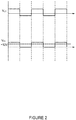
- Figure 2 shows several voltage waveforms for the power supply system 100 shown in Figure 1 .
- the diode D1 when the first transformer T1 voltage at the ends of the original winding T11 VL1 is forward voltageV 1 , the diode D1 is conducting and there is voltage output from the connecting point m between the first diode D1 and the first capacitor C1V m .
- the first transformer T1 original winding T11 VL1 is reverse voltage V 1 - V PN , the diode D1 is cut off, and there is no voltage output at the connection point m between the first diode D1 and first capacitor C1, that is, the voltage Vm at the connection point between the first diode D1 and the first capacitor C1 is 0.
- the auxiliary power output end O output voltage VO is the output voltage at the connection point m between the first diode D1 and the first capacitor C1V m .
- the auxiliary power supply output O output voltage VO is the output voltage at the connection point between the first diode D1 and first capacitor C1 after filtering V m (as shown in figure 2 + 12 v).
- the voltage of the first energy storage device 11V 1 , the output voltage V0 of the auxiliary power output terminal 0, and the number of turns on the primary winding T11 of thefirst transformer T1 are known N 11 , the number of required turns on the auxiliary winding T12 of the first transformer T1 can easily be obtained N 12 .
- the power supply system 100 can be a multi-source system. Therefore,the power system 100 can also include a second energy storage device 12 and a second converter 22 coupled to the second energy storage device 12. The output terminal of the second transformer 22 and the output terminals P and N of the first transformer 21 are connected together. There is a second inductor L2 between the second energy storage device 12 and the second transformer 22.
- the second energy storage device 12 can include a battery, super capacitor, a fuel cell and solar cell that is different from that of the first energy storage device 11.
- the second energy storage device 12 is a super capacitor.
- the second transformer 22 includes a third S3 and fourth switch S4 in series.
- the third switch S3 and fourth switch S4 can include a semiconductor switch and diode connected in parallel.
- An example of a semiconductor switch is an insulated gate bipolar transistor (Insulated Gate Bipolar Transistor, IGBT). Of course, other types of semi conductor switches can also be used.
- an auxiliary winding needs to be added via the tap between the inductor on the first transformer 21 on the current electric system, thereby changing the original existing inductor into a 9 transformd 1er (the first transformer T1).
- Adding a diode (the first diode D1) and a capacitor (the first capacitor C1) can realize an auxiliary power supply, thereby integrating an auxiliary power supply structure into the power supply system 100.
- this invention uses an integrated auxiliary power structure 100.
- This integrated structure only uses a few extra elements, but is able to realize all the necessary functions of an auxiliary power supply, thus simplifying the power supply design.
- the structure does not take up much space. Therefore, the power supply system and energy storage system 100 in this invention are small, but still able to provide a high power density.
- this power supply system 100 invention can greatly reduce costs.
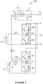
- FIG. 3 is a schematic circuit diagram of another possible power supply system 200 embodying the method in this invention.
- the difference with power supply system 100 in Figure 1 is that in the power system 200 shown in Figure 3 , the second energy storage device 11 is a super capacitor.
- the first transformer T1 is used to transform the high voltage from the super conductor to low voltage O from the auxiliary power output terminal 0.
- the power supply system 200 can be a multi-source system. Therefore,the power system 200 can also include a second energy storage device 12 and a second converter 22 coupled to the second energy storage device 12. The output terminal of the second transformer 22 and the output terminals P and N of the first transformer 21 are connected together. There is a separate conductor L2 between second energy storage device 12 and converter 22 second converter.
- the difference with power supply system 100 in Figure 1 is that in the power system 200 shown in Figure 3 , the second energy storage device 12 is a battery.
- the power supply system shown in Figure 3 can achieve an efficiency comparable to the power supply system 100 as shown in Figure 1 and is not repeated here.
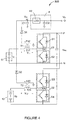
- FIG 4 is a schematic circuit diagram of another possible power supply system 300 embodying the method in this invention.
- the power supply system 300 is a multi-source system. Similar to the system 100 shown in Figure 1 , the power supply system 300 is a multi-source system 100 as shown in to figure 4 , used to provide auxiliary power output 0 and includes a first energy storage device 11, a first inverter 21 coupled to the first energy storage device 11, a first transformer T1, a first diode D1 a second energy storage device 12 and a second transformer 22 coupled with the second energy storage system 12.
- the power supply system 300 shown in Figure 4 also includes second transformer T2.
- the second transformer T2 transforms the high voltage from the second energy storage system 12 into low voltage V O from the auxiliary voltage output.
- the second transformer T2 includes the primary winding T21 and secondary winding T22.
- the primary winding T21 of the second transformer T2 is connected between the first energy storage device 12 and connection point A2 of the third switch S3 and fourth switch S4 of the second converter 22.
- the primary winding T11 of the second transformer T2 is connected with positive electrode side of the second energy storage device 12, and the negative electrode end of the primary winding T21 of the second transformer T2 is connected to the connection point A2 between the third switch S3 and fourth switch S4.
- the terminal of the secondary winding T22 of the transformer T2 is connected the connecting point m between the first diode D1 and the first capacitor C1 via the second diode D2, and the other terminal is connected to the earth.
- power supply system 300 can also include 4 filtering circuit, filtering circuit 4 coupled and connected to the m point of the first diode D1 and the junction of capacitor C1 and between the auxiliary power output O.
- the filter circuit 4 is to carry out fine voltage V m filtering at the connection point m between the first diode D1 and first capacitor C1.
- the filter circuit 4 can include a low pressure drop voltage stabilizer (LDO) 40 and a second capacitor C2.
- the input of the LDO 40 is coupled to the connection point m of the first diode D1 and first capacitor C1.
- One end of the second capacitor C2 is connected to the output of the LDO 40, and the other end of the second capacitor C2 is connected to the earth.
- the number of turns of primary winding T11 of this first transformer T1 is N 11
- the number of turns of the secondary winding T12 of first transformer T1 is N 12
- the voltage at the connection point m between the first diode D1 and the first capacitor C1 is V m
- the number of turns of the primary winding T21 of the second transformer T2 is N 21
- the number of turns on the auxiliary winding T22 of the second transformer T2 is N 22
- the voltage across the two terminals on the primary winding T21 for the second transformer is V L2 .
- the primary winding T11 of transformer T1 voltage V of both ends satisfy the following formula: V 1 ⁇ V PN ⁇ V L 1 ⁇ V 1
- V 1 represents the voltage of the first energy storage device 11 and V PN represents the voltage between the two outputs P and N from the first transformer 21.
- the primary winding T21 of transformer T2 voltage V L2 of both ends satisfy the following formula: V 2 ⁇ V PN ⁇ V L 2 ⁇ V 2
- V 2 represents the voltage of the second energy storage device 12.
- Figure 5 shows several voltage waveforms for the power supply system 300 shown in Figure 4 .
- the first diode D1 the voltages and the junction of a capacitor C1 m V m is equal to the first deputy winding of the transformer T1 T12 on both ends of the voltage;
- the first transformer T1 V L1 at the ends of the original winding T11 voltage to low voltage, and the second the T2 primary side of transformer voltage at the ends of the T21 V L2 for high voltage, the first diode D1 deadline, while the second diode D2 conduction, at this point the first diode D1 the voltages and the junction of a capacitor C1 m V m is equal
- N 12 N 11 ⁇ V m V 1
- the auxiliary power output end O output voltage V O is the output voltage at the connection point m between the first diode D1 and the first capacitor C1V m .
- the auxiliary power supply output O output voltage V O is the output voltageV m at the connection point between the first diode D1 and first capacitor C1 after filtering(as shown in figure 5 + 12 v).
- auxiliary power supply output voltage output voltage V O O you want the first turn of the original winding of transformer T1 T11 and N 11 second transformer T2 of the original winding turns for T21N 21 , easily obtained first deputy winding of the transformer T1 T12 required N 12 and second transformer T2 of vice winding coils T22 the required number of turns N 22 .
- an auxiliary winding needs to be added via the tap between the inductor on the first transformer 21 and each transformer in the second transformer 22 on the current electric system, thereby changing the original inductors on the first transformer 21 and second transformer 22 into a two transformers (the first transformer T1 second transformer T2).
- Adding two diodes (the first diode D1 and second diode D2) and a capacitor (the first capacitor C1) can realize an auxiliary power supply, thereby integrating an auxiliary power supply structure into the power supply system 300.
- this invention as shown in Figure 4 uses an integrated auxiliary power structure 300.
- This integrated structure only uses a few extra elements, but is able to realize all the necessary functions of an auxiliary power supply, thus simplifying the power supply design.
- the structure does not take up much space. Therefore, the power supply system and energy storage system 300 in this invention are small, but still able to provide a high power density.
- this power supply system 300 invention can greatly reduce costs.
- the invention also provides a kind of energy storage system.
- the energy system can include any of the power supply system 100, 200 or 300 in Figure 1 , Figure 3 and Figure 4 .
- the output terminals P and N of the first converter are connected to the DC bus load (not shown).
- the energy storage system also includes 100, 200, 300, used for power supply system for management and control of energy management system (not shown). Under the power system 100, 200, 300 including first energy storage device of the 11 cases, energy management system used to control the first energy storage device 11; When power systems, 100, 200, 300, including the first energy storage device 11 and the second energy storage device of 12 cases, energy management system used in the first energy storage device in 11 and 12 to control the second energy storage device.
- the energy storage system can be used as a dynamic application, applied to electric vehicles, or it can be used as a static application, applied in power grids.
- the DC bus load line of the energy storage system can includes the drive system of electric vehicle.
- the DC bus load line of the energy storage system of this present invention can include the inverter and the power grid of the inverter.
- the energy storage system of this invention as mentioned above is smaller and has a higher power density when used as shown in power supply systems 100, 200 and 300.
- this invention of the energy storage system can greatly reduce the cost.
Landscapes
- Engineering & Computer Science (AREA)
- Power Engineering (AREA)
- Transportation (AREA)
- Mechanical Engineering (AREA)
- Sustainable Energy (AREA)
- Sustainable Development (AREA)
- Life Sciences & Earth Sciences (AREA)
- General Physics & Mathematics (AREA)
- Automation & Control Theory (AREA)
- Radar, Positioning & Navigation (AREA)
- Electromagnetism (AREA)
- Physics & Mathematics (AREA)
- Charge And Discharge Circuits For Batteries Or The Like (AREA)
- Dc-Dc Converters (AREA)
- Direct Current Feeding And Distribution (AREA)
- Inverter Devices (AREA)
- Chemical & Material Sciences (AREA)
- Combustion & Propulsion (AREA)
Abstract
Description
- This invention is generally related to the energy supply technology domain, especially related to power supply systems as well as energy storage systems with power supply systems.
- Following the continual increase in global oil consumption and increasingly prominent environmental issues, reducing energy consumption and the development and use of reusable energy sources are a rapidly accelerating development trends. Following these developments, a new type of electric vehicle using renewable energy sources has come into being, including pure electric vehicles and hybrid vehicles.
- In the electric power system, there are usually two kinds of voltage, high voltage and low voltage. High voltage is for battery voltage, the total energy for the running and operation of the vehicle provided by the power battery. Low voltage is controlled voltage, which can be used for the motor control unit, dashboard and various lamps, etc. In the existing power system of the electric vehicle power system, a separate auxiliary power unit is usually needed for the high voltage of battery (for example, 48 v converted to low voltage 12 v). However, in the existing independent auxiliary power, a separate inverter is needed to provide auxiliary power supply, which results in high costs. In consideration of the space limitations of electric vehicles, adding this independent power supply is bound to take up a large amount of space. Therefore, within the limited space in this power system configuration, the separate auxiliary power structure will certainly cause low power density.
- Therefore, it is necessary to provide an improved system to solve at least one of the problems mentioned above.
- One aspect of this invention is to provide a power supply system, used to provide auxiliary power output and includes a first energy storage device, a first inverter coupled to the first energy storage device, a first transformer, a first diode and a capacitor. The first inverter includes a first switch and second switch in series. The first transformer transforms high voltage from the first energy storage device to the low voltage output from auxiliary power output terminal, and includes the primary winding and auxiliary winding. The primary winding of the transformer is connected to the first energy storage device and the junction of the first and second switch, and the homonymous terminal of the secondary winding of the terminal is connected to the auxiliary power output through the first diode, with the synonymous terminal connected to the earth; One end of which is connected to the first diode cathode and the other end is connected to the earth.
- Another aspect of this invention is to provide an energy storage system, which includes all the items of power supply systems described above, used to manage and control the energy management system. The output terminal of the first converter in the power system is connected to a DC bus load line.
- Compared with the existing independent auxiliary power structure, the power system and energy storage system in this invention use an integrated auxiliary power structure. This integrated structure only uses a few extra elements, but is able to realize all the necessary functions of an auxiliary power supply, thus simplifying the power supply design. The structure does not take up much space. Therefore, the power supply system and energy storage system in this invention are small, but still able to provide a high power density. In addition, this power supply system and the energy storage system invention can greatly reduce costs.
- You can get a clearer understanding of these and other characteristics, aspects and advantages of this invention by referring to the attached figures when reading the following detailed explanation. In the attached figures, the same element reference numbers are used to denote the same parts in all figures.
-
Figure 1 is a schematic circuit diagram of one possible power supply system embodying the method in this invention. -
Figure 2 shows several voltage waveforms for the power supply system shown inFigure 1 . -
Figure 3 is a schematic circuit diagram of another possible power supply system embodying the method in this invention. -
Figure 4 is a schematic circuit diagram of a further possible power supply system embodying the method in this invention. -
Figure 5 shows several voltage waveforms for the power supply system shown inFigure 4 . - In order to help technicians in this field to clearly understand this invention, the following combine figures with a detailed description of the specific implementation of this invention. In the following detailed descriptions of specific implementation methods, this specification does not describe some commonly known functions or configurations, to avoid unnecessary detail affecting the disclosure of this invention.
- Unless otherwise defined, the technical terms or scientific terms used in the claims and specification should be the ordinary meaning understood by a person of ordinary skill in the technical field of the present invention. "First", "second" and similar words used in the present specification and the claims do not denote any order, quantity, or importance, but are just used to distinguish different components. "A" or "a" and similar words do not mean a single unit, but indicate the presence of at least one. "Comprises" or "possesses" and other similar words imply that an element or object appearing before the "comprises" or "possesses" covers enumerated elements or objects and equivalents elements thereof appearing after the "comprises" or "possesses", without excluding other elements or objects. "Connected" or "coupled" and other similar words are not limited to physical or mechanical connections, but may include electrical connections, either in a direct or indirect manner.
-
Figure 1 is a schematic circuit diagram of one possible power supply system embodying the method in this invention. As shown inFigure 1 , a specific implementation of this invention is thepower supply system 100, used to provide auxiliary power output 0 and includes a firstenergy storage device 11, afirst inverter 21 coupled to the firstenergy storage device 11, a first transformer T1, a first diode D1 and a first capacitor C1. - The first
energy storage device 11 can include a battery, super capacitor, fuel cell or solar cell. In this specific implementation as shown inFigure 1 , the firstenergy storage device 11 is a battery. - The first inverter includes a first switch S1 and second switch S2 in series. The first switch S1 and second switch S2 can include a semiconductor switch and diode connected in parallel. An example of a semiconductor switch is an insulated gate bipolar transistor (Insulated Gate Bipolar Transistor, IGBT). Of course, other types of semi conductor switches can also be used.
- The first transformer T1 is used to transform the high voltage from the first energy storage device 11 (the battery) to low voltage VO from the auxiliary power output terminal 0 (e.g., for 12 v). The first transformer T1 includes the primary winding T11 and secondary winding T12. The primary winding T11 of the first transformer T1 is connected between the first
energy storage device 11 and connection point A1 of the first switch S1 and second switch S2 of thefirst converter 21. For example, in the example shown inFigure 1 , the primary winding T11 of the first transformer T1 is connected with positive electrode side of the firstenergy storage device 11, and the negative electrode end of theprimary winding 11 of the first transformer T1 is connected to the connection point A1 between the first switch S1 and second switch S2. The terminal of the secondary winding T12 of the transformer T1 is connected to the auxiliary power output end 0 by the first diode D1, and the end point of the auxiliary winding T12 of first transformer T1 is connected to the earth. - One end of the first capacitor C1 is connected to the diode D1 cathode, and the other end of the first capacitor C1 is connected to the earth.
- In this specific implementation of the invention , as shown in
Figure 1 , thepower supply system 100 can also include afiltering circuit 4. Thefiltering circuit 4 is coupled between the connection point m of the first diode D1 and first capacitor C1 and the auxiliary power output 0. Thefilter circuit 4 is to carry out fine voltageVm filtering at the connection point m between the first diode D1 and first capacitor C1. In an example, thefilter circuit 4 can include a low pressure drop voltage stabilizer (Low Dropout Regulator, LDO) 40 and a second capacitor C2. The input of the LDO 40 is coupled to the connection point m of the first diode D1 and first capacitor C1. One end of the second capacitor C2 is connected to the output of the LDO 40, and the other end of the second capacitor C2 is connected to the earth. - Referring to
Figure 1 , the primary winding T11 N11 of this first transformer T1N12, secondary winding T12 of first transformer T1, and primary winding T11 of the first transformer T1 are connected to the connection point m between the first diode D1 and first capacitor C1Vm. - According to the
Figure 1 , the primary winding T11 of transformer T1 voltage V of both ends satisfy the following formula:
- In the formula, V1 represents the voltage of the first
energy storage device 11 and VPN represents the voltage between the two outputs P and N from thefirst transformer 21. -
Figure 2 shows several voltage waveforms for thepower supply system 100 shown inFigure 1 . CombiningFigures 1 and2 , when the first transformer T1 voltage at the ends of the original winding T11 VL1 is forward voltageV1, the diode D1 is conducting and there is voltage output from the connecting point m between the first diode D1 and the first capacitor C1Vm. When the first transformer T1 original winding T11 VL1 is reverse voltage V1 - VPN, the diode D1 is cut off, and there is no voltage output at the connection pointm between the first diode D1 and first capacitor C1, that is, the voltage Vm at the connection point between the first diode D1 and the first capacitor C1 is 0. - Therefore, the number of turns on the auxiliary winding T12 of the first transformer T1N12 winding can be selected according to the following formula:

power system 100 as shown inFigure 1 does not include thefilter circuit 4. The auxiliary power output end O output voltage VO is the output voltage at the connection point m between the first diode D1 and the first capacitor C1Vm. When thepower supply system 100 as shown inFigure 1 does include afilter circuit 4, the auxiliary power supply output O output voltage VO is the output voltage at the connection point between the first diode D1 and first capacitor C1 after filtering Vm (as shown infigure 2 + 12 v). Therefore, if the voltage of the first energy storage device 11V1, the output voltage V0 of the auxiliary power output terminal 0, and the number of turns on the primary winding T11 of thefirst transformer T1 are known N11, the number of required turns on the auxiliary winding T12 of the first transformer T1 can easily be obtained N12. - In the specific implementation method shown in
Digram 1, thepower supply system 100 can be a multi-source system. Therefore,thepower system 100 can also include a secondenergy storage device 12 and asecond converter 22 coupled to the secondenergy storage device 12. The output terminal of thesecond transformer 22 and the output terminals P and N of thefirst transformer 21 are connected together. There is a second inductor L2 between the secondenergy storage device 12 and thesecond transformer 22. - The second
energy storage device 12 can include a battery, super capacitor, a fuel cell and solar cell that is different from that of the firstenergy storage device 11. In thepower system 100 shown inFigure 1 , the secondenergy storage device 12 is a super capacitor. - The
second transformer 22 includes a third S3 and fourth switch S4 in series. Similarly, the third switch S3 and fourth switch S4 can include a semiconductor switch and diode connected in parallel. An example of a semiconductor switch is an insulated gate bipolar transistor (Insulated Gate Bipolar Transistor, IGBT). Of course, other types of semi conductor switches can also be used. - In the
power supply system 100 inFigure 1 , an auxiliary winding needs to be added via the tap between the inductor on thefirst transformer 21 on the current electric system, thereby changing the original existing inductor into a 9 transformd 1er (the first transformer T1). Adding a diode (the first diode D1) and a capacitor (the first capacitor C1) can realize an auxiliary power supply, thereby integrating an auxiliary power supply structure into thepower supply system 100. - Compared with the existing independent auxiliary power structure, this invention uses an integrated
auxiliary power structure 100. This integrated structure only uses a few extra elements, but is able to realize all the necessary functions of an auxiliary power supply, thus simplifying the power supply design. The structure does not take up much space. Therefore, the power supply system andenergy storage system 100 in this invention are small, but still able to provide a high power density. In addition, thispower supply system 100 invention can greatly reduce costs. -
Figure 3 is a schematic circuit diagram of another possiblepower supply system 200 embodying the method in this invention. InFigure 3 , the difference withpower supply system 100 inFigure 1 is that in thepower system 200 shown inFigure 3 , the secondenergy storage device 11 is a super capacitor. The first transformer T1 is used to transform the high voltage from the super conductor to low voltage O from the auxiliary power output terminal 0. - In the specific implementation method shown in
Digram 3, thepower supply system 200 can be a multi-source system. Therefore,thepower system 200 can also include a secondenergy storage device 12 and asecond converter 22 coupled to the secondenergy storage device 12. The output terminal of thesecond transformer 22 and the output terminals P and N of thefirst transformer 21 are connected together. There is a separate conductor L2 between secondenergy storage device 12 andconverter 22 second converter. - However, the difference with
power supply system 100 inFigure 1 is that in thepower system 200 shown inFigure 3 , the secondenergy storage device 12 is a battery. - The power supply system shown in
Figure 3 can achieve an efficiency comparable to thepower supply system 100 as shown inFigure 1 and is not repeated here. -
Figure 4 is a schematic circuit diagram of another possiblepower supply system 300 embodying the method in this invention. In the specific implementation as shown inFigure 4 , thepower supply system 300 is a multi-source system. Similar to thesystem 100 shown inFigure 1 , thepower supply system 300 is amulti-source system 100 as shown in tofigure 4 , used to provide auxiliary power output 0 and includes a firstenergy storage device 11, afirst inverter 21 coupled to the firstenergy storage device 11, a first transformer T1, a first diode D1 a secondenergy storage device 12 and asecond transformer 22 coupled with the secondenergy storage system 12. - The difference with the
multi-source system 100 as shown inFigure 1 is that thepower supply system 300 shown inFigure 4 also includes second transformer T2. The second transformer T2 transforms the high voltage from the secondenergy storage system 12 into low voltage VO from the auxiliary voltage output. The second transformer T2 includes the primary winding T21 and secondary winding T22. The primary winding T21 of the second transformer T2 is connected between the firstenergy storage device 12 and connection point A2 of the third switch S3 and fourth switch S4 of thesecond converter 22. For example, in the example shown inFigure 4 , the primary winding T11 of the second transformer T2 is connected with positive electrode side of the secondenergy storage device 12, and the negative electrode end of the primary winding T21 of the second transformer T2 is connected to the connection point A2 between the third switch S3 and fourth switch S4. The terminal of the secondary winding T22 of the transformer T2 is connected the connecting point m between the first diode D1 and the first capacitor C1 via the second diode D2, and the other terminal is connected to the earth. - In this specific implementation of this invention , as shown in
figure 4 power supply system 300 can also include 4 filtering circuit, filteringcircuit 4 coupled and connected to the m point of the first diode D1 and the junction of capacitor C1 and between the auxiliary power output O. Thefilter circuit 4 is to carry out fine voltage Vm filtering at the connection point m between the first diode D1 and first capacitor C1. In an example, thefilter circuit 4 can include a low pressure drop voltage stabilizer (LDO) 40 and a second capacitor C2. The input of theLDO 40 is coupled to the connection point m of the first diode D1 and first capacitor C1. One end of the second capacitor C2 is connected to the output of theLDO 40, and the other end of the second capacitor C2 is connected to the earth. - Referring to
Figure 4 , the number of turns of primary winding T11 of this first transformer T1 is N11, the number of turns of the secondary winding T12 of first transformer T1 is N12, the voltage across the two terminals of the primary winding T11 for the transformer T1 VL1, and the voltage at the connection point m between the first diode D1 and the first capacitor C1 is Vm. The number of turns of the primary winding T21 of the second transformer T2 is N21, the number of turns on the auxiliary winding T22 of the second transformer T2 is N22 and the voltage across the two terminals on the primary winding T21 for the second transformer is VL2. - According to the
Figure 4 , the primary winding T11 of transformer T1 voltage V of both ends satisfy the following formula:
- In the formula, V1 represents the voltage of the first
energy storage device 11 and VPN represents the voltage between the two outputs P and N from thefirst transformer 21. - According to the
Figure 4 , the primary winding T21 of transformer T2 voltage VL2 of both ends satisfy the following formula:
- In the formula , V2 represents the voltage of the second
energy storage device 12. -
Figure 5 shows several voltage waveforms for thepower supply system 300 shown inFigure 4 . Combined with the reference as shown infigure 4 andfigure 5 , when the first primary side of transformer T1 VL1 at the ends of the voltage for high voltage winding T11, while the second the T2 primary side of transformer voltage at the ends of the T21 VL2 for low voltage, the first diode D1 conduction, while the second diode D2 deadline, at this point, the first diode D1 the voltages and the junction of a capacitor C1 m Vm is equal to the first deputy winding of the transformer T1 T12 on both ends of the voltage;When the first transformer T1 VL1 at the ends of the original winding T11 voltage to low voltage, and the second the T2 primary side of transformer voltage at the ends of the T21 VL2 for high voltage, the first diode D1 deadline, while the second diode D2 conduction, at this point, the first diode D1 the voltages and the junction of a capacitor C1 m Vm is equal to the second the T2 vice side of the transformer voltage at the ends of the T22;When the first primary side of transformer T1 VL1 at the ends of the voltage and the second transformer winding T11 T2 of the original winding voltage at the ends of the T21 VL2 are low voltage, the first diode is the second diode D1 and D2 are deadline, at this point, the first diode D1 and the junction of a capacitor C1 m no voltage output, namely the first diode D1 the voltages and the junction of a capacitor C1 m Vm is 0. - Therefore, the number of turns on the auxiliary winding T12 of the first transformer T1 winding N12 can be selected according to the following formula:

- Therefore, the number of turns on the auxiliary winding T22 of the first transformer T1 winding N22 can be selected according to the following formula:

power system 300 as shown inFigure 4 does not include thefilter circuit 4. The auxiliary power output end O output voltage VO is the output voltage at the connection point m between the first diode D1 and the first capacitor C1Vm. When thepower supply system 300 as shown inFigure 4 does include afilter circuit 4, the auxiliary power supply output O output voltage VO is the output voltageVm at the connection point between the first diode D1 and first capacitor C1 after filtering(as shown infigure 5 + 12 v). Therefore, in the known voltage of the firstenergy storage device 11V1, 12 second energy storage device V2, auxiliary power supply output voltage output voltage VO, O you want the first turn of the original winding of transformer T1 T11 and N11 second transformer T2 of the original winding turns for T21N21, easily obtained first deputy winding of the transformer T1 T12 required N12 and second transformer T2 of vice winding coils T22 the required number of turns N22. - In the
power supply system 300 inFigure 5 , an auxiliary winding needs to be added via the tap between the inductor on thefirst transformer 21 and each transformer in thesecond transformer 22 on the current electric system, thereby changing the original inductors on thefirst transformer 21 andsecond transformer 22 into a two transformers (the first transformer T1 second transformer T2). Adding two diodes (the first diode D1 and second diode D2) and a capacitor (the first capacitor C1) can realize an auxiliary power supply, thereby integrating an auxiliary power supply structure into thepower supply system 300. - Compared with the existing independent auxiliary power structure, this invention as shown in
Figure 4 uses an integratedauxiliary power structure 300. This integrated structure only uses a few extra elements, but is able to realize all the necessary functions of an auxiliary power supply, thus simplifying the power supply design. The structure does not take up much space. Therefore, the power supply system andenergy storage system 300 in this invention are small, but still able to provide a high power density. In addition, thispower supply system 300 invention can greatly reduce costs. - In addition, the invention also provides a kind of energy storage system. The energy system can include any of the
power supply system Figure 1 ,Figure 3 andFigure 4 . Insystems - The energy storage system also includes 100, 200, 300, used for power supply system for management and control of energy management system (not shown). Under the
power system energy storage device 11; When power systems, 100, 200, 300, including the firstenergy storage device 11 and the second energy storage device of 12 cases, energy management system used in the first energy storage device in 11 and 12 to control the second energy storage device. - The energy storage system can be used as a dynamic application, applied to electric vehicles, or it can be used as a static application, applied in power grids.
- When the energy storage system of this invention is applied to electric vehicles, the DC bus load line of the energy storage system can includes the drive system of electric vehicle.
- When the energy storage system of this invention as static applications, the DC bus load line of the energy storage system of this present invention can include the inverter and the power grid of the inverter.
- The energy storage system of this invention as mentioned above is smaller and has a higher power density when used as shown in
power supply systems - Although the present invention is described with reference to specific implementation methods, technicians in the field should understand that many modifications and variations may be made for the present invention. Therefore, it should be aware that, intention of the claims lies in all the modifications and variations covered in a real concept and scope of the present invention.
Claims (10)
- A power supply system (100) which includes:an auxiliary power output terminal, used to provide auxiliary power;a first energy storage device (11);a first inverter (21), which includes a first switch and second switch connected in series, the first inverter is coupled to the first energy storage device (11);a first transformer transforms high voltage from the first energy storage device (11) to the low voltage output from auxiliary power output terminal, and includes the primary winding and auxiliary winding, the primary winding of the transformer is connected to the first energy storage device and the junction of the first and second switch, and the homonymous terminal of the secondary winding of the terminal is connected to the auxiliary power output through the first diode, with the synonymous terminal connected to the earth;a first capacitor (61), one end of which is connected to the first diode cathode and the other end is connected to the earth.
- The power supply system according to Claim 1, wherein the number of turns on the secondary winding of the first transformer N12 is calculated according to the following formula:

- The power supply system according to Claim 1 or Claim 2, further including:a second energy storage device; anda second converter, which includes a third switch and fourth switch connected in series, the above-mentioned second converter is coupled to the second energy storage device, and the output terminal of the second converter and output terminal of the first converter are connected together.
- The power supply system according to any preceding Claim, the first energy storage device includes a battery and a second energy storage device including a super capacitor, alternatively, the power system can include a first energy storage device with a super capacitor, and a second energy storage device with a battery.
- The power supply system according to any preceding Claim, but also including:a second transformer, which transforms high voltage from the second energy storage device to low voltage, and includes a primary winding and auxiliary winding, the primary winding of the transformer is connected to the second energy storage device and the junction of the third and fourth switched, and the homonymous terminal of the secondary winding of the terminal is connected to the connection point between the first diode and the first capacitor through the second diode, with the synonymous terminal connected to the earth;
- The power supply system according to any preceding Claim, wherein the number of turns on the secondary winding of the second transformer is calculated N22 according to the following formula:

- The power supply system according to any preceding Claim, further including:a filter circuit, coupled between the connection point between the first diode and capacitor and the auxiliary power output terminal.
- The power supply system according to any preceding Claim, with the filter circuit also including:an LDO voltage stabilizer, with the LDO voltage stabilizer input coupled to the connection point between the first diode and first capacitor, anda second capacitor, with one end of the second capacitor connected to output of the LDO, and the other end connected to the earth.
- An energy storage system, which includes all the items of power supply systems in any of Claims 1 to 8, used to manage and control the energy management system, wherein the output terminal of the first converter in the power system is connected to a DC bus load line.
- The energy storage system described in Claim 9, with the DC bus load line including an electric drive system for electric vehicles or an inverter and power grid connected to the inverter.
Applications Claiming Priority (1)
| Application Number | Priority Date | Filing Date | Title |
|---|---|---|---|
| CN201510149774.5A CN106160206A (en) | 2015-03-31 | 2015-03-31 | Power-supply system and energy storage system |
Publications (1)
| Publication Number | Publication Date |
|---|---|
| EP3078538A1 true EP3078538A1 (en) | 2016-10-12 |
Family
ID=55696972
Family Applications (1)
| Application Number | Title | Priority Date | Filing Date |
|---|---|---|---|
| EP16162904.3A Withdrawn EP3078538A1 (en) | 2015-03-31 | 2016-03-30 | Power generating system and energy storage system |
Country Status (8)
| Country | Link |
|---|---|
| US (1) | US10483872B2 (en) |
| EP (1) | EP3078538A1 (en) |
| JP (1) | JP6775978B2 (en) |
| KR (1) | KR102614468B1 (en) |
| CN (1) | CN106160206A (en) |
| BR (1) | BR102016007002B1 (en) |
| CA (1) | CA2923952C (en) |
| MX (1) | MX366720B (en) |
Cited By (1)
| Publication number | Priority date | Publication date | Assignee | Title |
|---|---|---|---|---|
| EP4339004A1 (en) * | 2022-09-13 | 2024-03-20 | MAHLE International GmbH | Power conversion topology |
Families Citing this family (9)
| Publication number | Priority date | Publication date | Assignee | Title |
|---|---|---|---|---|
| US9878635B1 (en) * | 2013-02-13 | 2018-01-30 | University Of Maryland | Powertrain system in plug-in electric vehicles |
| CN106160206A (en) * | 2015-03-31 | 2016-11-23 | 通用电气公司 | Power-supply system and energy storage system |
| CN107294145A (en) * | 2016-03-30 | 2017-10-24 | 通用电气公司 | charging device, system and method |
| PL233173B1 (en) * | 2017-07-20 | 2019-09-30 | Zpue Spolka Akcyjna | Transformer station with energy store |
| US12021468B2 (en) | 2018-03-23 | 2024-06-25 | Mitsubishi Electric Corporation | Motor drive device, electric blower, electric vacuum cleaner, and hand dryer |
| CN109301942A (en) * | 2018-10-31 | 2019-02-01 | 东莞市新瑞能源技术有限公司 | A battery container intelligent energy storage system and its working process |
| JP7278817B2 (en) * | 2019-03-20 | 2023-05-22 | 株式会社東芝 | Energy storage system and energy storage string |
| CN110091727B (en) * | 2019-06-20 | 2022-03-08 | 重庆大学 | A decentralized energy management method for electric vehicle hybrid system |
| JP7714900B2 (en) * | 2021-04-13 | 2025-07-30 | トヨタ自動車株式会社 | Service plug, on-board power supply, vehicle |
Citations (5)
| Publication number | Priority date | Publication date | Assignee | Title |
|---|---|---|---|---|
| JP2002209302A (en) * | 2001-01-12 | 2002-07-26 | Nissan Motor Co Ltd | Power supply device for electric vehicle and DC voltage conversion circuit used for the power supply device |
| US20020122326A1 (en) * | 2001-03-02 | 2002-09-05 | Delta Electronics, Inc. | Auxiliary output voltage control circuit of flyback power converter with a magnetic amplifier |
| EP2012406A1 (en) * | 2006-04-24 | 2009-01-07 | Toyota Jidosha Kabushiki Kaisha | Power supply system and vehicle |
| US20140232187A1 (en) * | 2013-02-20 | 2014-08-21 | Cambridge Semiconductor Limited | Auxiliary recharge |
| US20140281638A1 (en) * | 2013-03-15 | 2014-09-18 | Freescale, Inc. | Application of normally closed power semiconductor devices |
Family Cites Families (26)
| Publication number | Priority date | Publication date | Assignee | Title |
|---|---|---|---|---|
| JPH08298769A (en) * | 1995-04-26 | 1996-11-12 | Hitachi Ltd | Switching power supply |
| JPH10248247A (en) * | 1997-03-04 | 1998-09-14 | Hitachi Ltd | Boost chopper circuit |
| US7252165B1 (en) | 2000-04-26 | 2007-08-07 | Bowling Green State University | Hybrid electric vehicle |
| JP2004088814A (en) * | 2002-08-22 | 2004-03-18 | Nissin Electric Co Ltd | Dc-dc converter |
| JP4043321B2 (en) * | 2002-08-29 | 2008-02-06 | 松下電器産業株式会社 | Switching power supply |
| US7259469B2 (en) | 2003-07-31 | 2007-08-21 | Scs Frigette Inc. | Vehicle auxiliary power unit, assembly, and related methods |
| ES2522278T3 (en) | 2004-01-29 | 2014-11-14 | Mitsubishi Denki Kabushiki Kaisha | Auxiliary electric power supply for vehicle |
| US7518886B1 (en) * | 2005-02-18 | 2009-04-14 | Virginia Tech Intellectual Properties, Inc. | Multiphase soft switched DC/DC converter and active control technique for fuel cell ripple current elimination |
| JP2006340432A (en) * | 2005-05-31 | 2006-12-14 | Sumida Corporation | Switching converter |
| JP2007189771A (en) * | 2006-01-11 | 2007-07-26 | Fuji Electric Device Technology Co Ltd | Power supply |
| JP2009131107A (en) * | 2007-11-27 | 2009-06-11 | Tokyo Electric Power Co Inc:The | AC / DC converter |
| JP5099344B2 (en) * | 2008-01-18 | 2012-12-19 | 本田技研工業株式会社 | Power converter |
| JP4525817B2 (en) * | 2008-10-30 | 2010-08-18 | サンケン電気株式会社 | Switching power supply |
| RU2551690C2 (en) | 2009-04-27 | 2015-05-27 | Вольво Ластвагнар Аб | Accumulator batteries charging system for hybrid electrical transportation vehicle |
| CN201478863U (en) | 2009-08-06 | 2010-05-19 | 东南大学 | On-board auxiliary power for improved fuel efficiency and reduced emissions |
| WO2011036758A1 (en) | 2009-09-25 | 2011-03-31 | トヨタ自動車株式会社 | Vehicle charging system and electric vehicle equipped with same |
| JP2012065501A (en) * | 2010-09-17 | 2012-03-29 | Toyota Motor Corp | Power supply device for vehicle |
| US9780716B2 (en) | 2010-11-19 | 2017-10-03 | General Electric Company | High power-density, high back emf permanent magnet machine and method of making same |
| US20120221287A1 (en) * | 2011-02-28 | 2012-08-30 | General Electric Company, A New York Corporation | System and Methods for Improving Power Handling of an Electronic Device |
| CN102222976A (en) * | 2011-06-27 | 2011-10-19 | 深圳市英威腾电源有限公司 | Auxiliary power supply and power supply system for power system |
| EP2682309B1 (en) | 2012-07-02 | 2015-11-18 | Autoliv Development AB | A power supply arrangement |
| US9755534B2 (en) * | 2013-02-14 | 2017-09-05 | Nuvolta Technologies, Inc. | High efficiency high frequency resonant power conversion |
| US9806637B2 (en) * | 2013-04-30 | 2017-10-31 | Futurewei Technologies, Inc. | Soft switching inverter device and method |
| US9819271B2 (en) * | 2013-09-30 | 2017-11-14 | O2Micro, Inc. | Power converters |
| TWI501529B (en) * | 2013-12-06 | 2015-09-21 | Ind Tech Res Inst | Dc-dc power conversion apparatus and method |
| CN106160206A (en) * | 2015-03-31 | 2016-11-23 | 通用电气公司 | Power-supply system and energy storage system |
-
2015
- 2015-03-31 CN CN201510149774.5A patent/CN106160206A/en active Pending
-
2016
- 2016-03-17 CA CA2923952A patent/CA2923952C/en active Active
- 2016-03-24 JP JP2016059361A patent/JP6775978B2/en active Active
- 2016-03-28 KR KR1020160036624A patent/KR102614468B1/en active Active
- 2016-03-30 MX MX2016004110A patent/MX366720B/en active IP Right Grant
- 2016-03-30 BR BR102016007002-3A patent/BR102016007002B1/en not_active IP Right Cessation
- 2016-03-30 EP EP16162904.3A patent/EP3078538A1/en not_active Withdrawn
- 2016-03-31 US US15/086,218 patent/US10483872B2/en active Active
Patent Citations (5)
| Publication number | Priority date | Publication date | Assignee | Title |
|---|---|---|---|---|
| JP2002209302A (en) * | 2001-01-12 | 2002-07-26 | Nissan Motor Co Ltd | Power supply device for electric vehicle and DC voltage conversion circuit used for the power supply device |
| US20020122326A1 (en) * | 2001-03-02 | 2002-09-05 | Delta Electronics, Inc. | Auxiliary output voltage control circuit of flyback power converter with a magnetic amplifier |
| EP2012406A1 (en) * | 2006-04-24 | 2009-01-07 | Toyota Jidosha Kabushiki Kaisha | Power supply system and vehicle |
| US20140232187A1 (en) * | 2013-02-20 | 2014-08-21 | Cambridge Semiconductor Limited | Auxiliary recharge |
| US20140281638A1 (en) * | 2013-03-15 | 2014-09-18 | Freescale, Inc. | Application of normally closed power semiconductor devices |
Cited By (1)
| Publication number | Priority date | Publication date | Assignee | Title |
|---|---|---|---|---|
| EP4339004A1 (en) * | 2022-09-13 | 2024-03-20 | MAHLE International GmbH | Power conversion topology |
Also Published As
| Publication number | Publication date |
|---|---|
| MX2016004110A (en) | 2016-09-29 |
| BR102016007002A2 (en) | 2016-10-25 |
| US20160294304A1 (en) | 2016-10-06 |
| CA2923952A1 (en) | 2016-09-30 |
| KR102614468B1 (en) | 2023-12-14 |
| KR20160117239A (en) | 2016-10-10 |
| MX366720B (en) | 2019-07-22 |
| JP2016195532A (en) | 2016-11-17 |
| CN106160206A (en) | 2016-11-23 |
| CA2923952C (en) | 2023-08-29 |
| US10483872B2 (en) | 2019-11-19 |
| BR102016007002B1 (en) | 2022-08-16 |
| JP6775978B2 (en) | 2020-10-28 |
Similar Documents
| Publication | Publication Date | Title |
|---|---|---|
| US10483872B2 (en) | Power supply system and energy storage system | |
| EP3163734B1 (en) | Dc-dc converter with high transformer ratio | |
| US20190329663A1 (en) | Charging device and on board power supply device | |
| US9000740B2 (en) | Two-directional current double-boost quadratic DC/DC converter | |
| US9209698B2 (en) | Electric power conversion device | |
| DE102017220289A1 (en) | POWER CONVERSION DEVICE | |
| DE102011083203A1 (en) | Systems and Methods for Providing Power to a Load Based on a Control Strategy | |
| CA2420973A1 (en) | High efficiency fuel cell power conditioner | |
| CN103560666A (en) | Four-switch voltage boosting and reducing converter with low ripples and control method thereof | |
| EP3223417A1 (en) | Three-port convertor having integrated magnetic and zero-port current ripple | |
| DE102015220309A1 (en) | CHARGER FOR ONE VEHICLE | |
| US9614388B2 (en) | Output stage of a charging device, including a transformer, rectifier, converter, capacitor, storage device and a use thereof | |
| US20220173652A1 (en) | Power conversion system and virtual dc voltage generator circuit | |
| De Souza et al. | Bidirectional current-fed flyback-push-pull DC-DC converter | |
| DE102013209302A1 (en) | Current-fed full-bridge DC-DC converter | |
| DE102012209753A1 (en) | An attenuation circuit for an energy storage device and method for attenuating vibrations of the output current of an energy storage device | |
| US12040618B2 (en) | Power conversion system including a second circuit being configured to control a current or power such that the current or the power is synchronized with power ripples caused by the AC power supply or the AC load | |
| US11349402B2 (en) | DC voltage converter arrangement, fuel cell vehicle and method for operating a DC voltage converter arrangement | |
| CN203608084U (en) | Four-switch boost-buck converter with low ripple | |
| KR102028480B1 (en) | High Efficiency and Low Cost Multi-Output Converter | |
| US10347948B2 (en) | Device for providing an electrical voltage as well as drive arrangement and method | |
| Rahman et al. | Sizing of Electric Vehicle Power Converter Based on Distributed Operating Points | |
| Gruner et al. | High step-up DC-DC converter with input current sharing based on the forward converter | |
| KR20190106038A (en) | ZVS Double-Ended Active Clamp Forward Converter with Low Magnetizing Offset Current | |
| JP2009005487A (en) | Power system |
Legal Events
| Date | Code | Title | Description |
|---|---|---|---|
| PUAI | Public reference made under article 153(3) epc to a published international application that has entered the european phase |
Free format text: ORIGINAL CODE: 0009012 |
|
| AK | Designated contracting states |
Kind code of ref document: A1 Designated state(s): AL AT BE BG CH CY CZ DE DK EE ES FI FR GB GR HR HU IE IS IT LI LT LU LV MC MK MT NL NO PL PT RO RS SE SI SK SM TR |
|
| AX | Request for extension of the european patent |
Extension state: BA ME |
|
| STAA | Information on the status of an ep patent application or granted ep patent |
Free format text: STATUS: REQUEST FOR EXAMINATION WAS MADE |
|
| 17P | Request for examination filed |
Effective date: 20170412 |
|
| RBV | Designated contracting states (corrected) |
Designated state(s): AL AT BE BG CH CY CZ DE DK EE ES FI FR GB GR HR HU IE IS IT LI LT LU LV MC MK MT NL NO PL PT RO RS SE SI SK SM TR |
|
| STAA | Information on the status of an ep patent application or granted ep patent |
Free format text: STATUS: EXAMINATION IS IN PROGRESS |
|
| 17Q | First examination report despatched |
Effective date: 20201110 |
|
| REG | Reference to a national code |
Ref country code: DE Ref legal event code: R079 Free format text: PREVIOUS MAIN CLASS: B60L0011180000 Ipc: B60L0001000000 |
|
| GRAP | Despatch of communication of intention to grant a patent |
Free format text: ORIGINAL CODE: EPIDOSNIGR1 |
|
| STAA | Information on the status of an ep patent application or granted ep patent |
Free format text: STATUS: GRANT OF PATENT IS INTENDED |
|
| RIC1 | Information provided on ipc code assigned before grant |
Ipc: H02M 3/156 20060101ALI20220411BHEP Ipc: H02M 3/158 20060101ALI20220411BHEP Ipc: B60L 58/20 20190101ALI20220411BHEP Ipc: B60L 50/40 20190101ALI20220411BHEP Ipc: B60L 1/14 20060101ALI20220411BHEP Ipc: B60L 1/00 20060101AFI20220411BHEP |
|
| INTG | Intention to grant announced |
Effective date: 20220512 |
|
| STAA | Information on the status of an ep patent application or granted ep patent |
Free format text: STATUS: THE APPLICATION IS DEEMED TO BE WITHDRAWN |
|
| 18D | Application deemed to be withdrawn |
Effective date: 20220923 |