EP3078470B1 - Mold for resin injection molding - Google Patents
Mold for resin injection molding Download PDFInfo
- Publication number
- EP3078470B1 EP3078470B1 EP15173292.2A EP15173292A EP3078470B1 EP 3078470 B1 EP3078470 B1 EP 3078470B1 EP 15173292 A EP15173292 A EP 15173292A EP 3078470 B1 EP3078470 B1 EP 3078470B1
- Authority
- EP
- European Patent Office
- Prior art keywords
- mold
- shaped portion
- density
- injection molding
- resin injection
- Prior art date
- Legal status (The legal status is an assumption and is not a legal conclusion. Google has not performed a legal analysis and makes no representation as to the accuracy of the status listed.)
- Active
Links
Images



Classifications
-
- B—PERFORMING OPERATIONS; TRANSPORTING
- B29—WORKING OF PLASTICS; WORKING OF SUBSTANCES IN A PLASTIC STATE IN GENERAL
- B29C—SHAPING OR JOINING OF PLASTICS; SHAPING OF MATERIAL IN A PLASTIC STATE, NOT OTHERWISE PROVIDED FOR; AFTER-TREATMENT OF THE SHAPED PRODUCTS, e.g. REPAIRING
- B29C33/00—Moulds or cores; Details thereof or accessories therefor
- B29C33/38—Moulds or cores; Details thereof or accessories therefor characterised by the material or the manufacturing process
- B29C33/3814—Porous moulds
-
- B—PERFORMING OPERATIONS; TRANSPORTING
- B29—WORKING OF PLASTICS; WORKING OF SUBSTANCES IN A PLASTIC STATE IN GENERAL
- B29C—SHAPING OR JOINING OF PLASTICS; SHAPING OF MATERIAL IN A PLASTIC STATE, NOT OTHERWISE PROVIDED FOR; AFTER-TREATMENT OF THE SHAPED PRODUCTS, e.g. REPAIRING
- B29C45/00—Injection moulding, i.e. forcing the required volume of moulding material through a nozzle into a closed mould; Apparatus therefor
- B29C45/17—Component parts, details or accessories; Auxiliary operations
- B29C45/1703—Introducing an auxiliary fluid into the mould
-
- B—PERFORMING OPERATIONS; TRANSPORTING
- B29—WORKING OF PLASTICS; WORKING OF SUBSTANCES IN A PLASTIC STATE IN GENERAL
- B29C—SHAPING OR JOINING OF PLASTICS; SHAPING OF MATERIAL IN A PLASTIC STATE, NOT OTHERWISE PROVIDED FOR; AFTER-TREATMENT OF THE SHAPED PRODUCTS, e.g. REPAIRING
- B29C45/00—Injection moulding, i.e. forcing the required volume of moulding material through a nozzle into a closed mould; Apparatus therefor
- B29C45/17—Component parts, details or accessories; Auxiliary operations
- B29C45/72—Heating or cooling
- B29C45/73—Heating or cooling of the mould
-
- B—PERFORMING OPERATIONS; TRANSPORTING
- B22—CASTING; POWDER METALLURGY
- B22F—WORKING METALLIC POWDER; MANUFACTURE OF ARTICLES FROM METALLIC POWDER; MAKING METALLIC POWDER; APPARATUS OR DEVICES SPECIALLY ADAPTED FOR METALLIC POWDER
- B22F10/00—Additive manufacturing of workpieces or articles from metallic powder
- B22F10/20—Direct sintering or melting
-
- B—PERFORMING OPERATIONS; TRANSPORTING
- B22—CASTING; POWDER METALLURGY
- B22F—WORKING METALLIC POWDER; MANUFACTURE OF ARTICLES FROM METALLIC POWDER; MAKING METALLIC POWDER; APPARATUS OR DEVICES SPECIALLY ADAPTED FOR METALLIC POWDER
- B22F5/00—Manufacture of workpieces or articles from metallic powder characterised by the special shape of the product
- B22F5/007—Manufacture of workpieces or articles from metallic powder characterised by the special shape of the product of moulds
-
- B—PERFORMING OPERATIONS; TRANSPORTING
- B29—WORKING OF PLASTICS; WORKING OF SUBSTANCES IN A PLASTIC STATE IN GENERAL
- B29C—SHAPING OR JOINING OF PLASTICS; SHAPING OF MATERIAL IN A PLASTIC STATE, NOT OTHERWISE PROVIDED FOR; AFTER-TREATMENT OF THE SHAPED PRODUCTS, e.g. REPAIRING
- B29C45/00—Injection moulding, i.e. forcing the required volume of moulding material through a nozzle into a closed mould; Apparatus therefor
- B29C45/17—Component parts, details or accessories; Auxiliary operations
- B29C45/72—Heating or cooling
- B29C45/7207—Heating or cooling of the moulded articles
-
- B—PERFORMING OPERATIONS; TRANSPORTING
- B29—WORKING OF PLASTICS; WORKING OF SUBSTANCES IN A PLASTIC STATE IN GENERAL
- B29C—SHAPING OR JOINING OF PLASTICS; SHAPING OF MATERIAL IN A PLASTIC STATE, NOT OTHERWISE PROVIDED FOR; AFTER-TREATMENT OF THE SHAPED PRODUCTS, e.g. REPAIRING
- B29C45/00—Injection moulding, i.e. forcing the required volume of moulding material through a nozzle into a closed mould; Apparatus therefor
- B29C45/17—Component parts, details or accessories; Auxiliary operations
- B29C45/72—Heating or cooling
- B29C45/73—Heating or cooling of the mould
- B29C45/7312—Construction of heating or cooling fluid flow channels
-
- B—PERFORMING OPERATIONS; TRANSPORTING
- B29—WORKING OF PLASTICS; WORKING OF SUBSTANCES IN A PLASTIC STATE IN GENERAL
- B29L—INDEXING SCHEME ASSOCIATED WITH SUBCLASS B29C, RELATING TO PARTICULAR ARTICLES
- B29L2031/00—Other particular articles
- B29L2031/757—Moulds, cores, dies
-
- Y—GENERAL TAGGING OF NEW TECHNOLOGICAL DEVELOPMENTS; GENERAL TAGGING OF CROSS-SECTIONAL TECHNOLOGIES SPANNING OVER SEVERAL SECTIONS OF THE IPC; TECHNICAL SUBJECTS COVERED BY FORMER USPC CROSS-REFERENCE ART COLLECTIONS [XRACs] AND DIGESTS
- Y02—TECHNOLOGIES OR APPLICATIONS FOR MITIGATION OR ADAPTATION AGAINST CLIMATE CHANGE
- Y02P—CLIMATE CHANGE MITIGATION TECHNOLOGIES IN THE PRODUCTION OR PROCESSING OF GOODS
- Y02P10/00—Technologies related to metal processing
- Y02P10/25—Process efficiency
Definitions
- the present invention relates to a mold for resin injection molding to be manufactured by three-dimensional laser sintering.
- JP 2007160580 (A ) it has not been particularly studied to effectively achieve heating and cooling by a blown or sucked gas with efficiency during resin injection molding and to cause gas to smoothly flow when filling resin.
- JP2009233980 (A ) US2011/045120A1
- Japanese Published Unexamined Patent Application No. H08-300363 it is intended to achieve the heating and cooling as described above with efficiency by adopting a constitution in which all of the ventilation channels through which a gas blown or sucked by a primary vent passes and a secondary vent which are in contact with a resin molding portion are formed by a low-density shaped portion.
- EP 2 581 155 A1 describes a method for manufacturing a three-dimensional shaped object, wherein a part of a surface portion of the three-dimensional shaped object is formed as a low-density solidified portion whose solidified density ranges from 50 % to 90 % so that an application of pressure can be performed by a gas flowing through the low-density solidified portion.
- the ventilation volume per unit area of a gas that flows in or out in a section with the resin molding portion is not always uniform, resulting in the case where uniform heating and cooling arise.
- a basic construction of the present invention is as follows: A mold for resin injection molding having a shaping region formed by a low-density shaped portion having a sintered density that allows a gas discharged with filling of a gas or resin blown or sucked in heating or cooling to pass therethrough and a high-density shaped portion having a sintered density that does not allow the gas to pass therethrough, wherein each ventilation channel for gas exists between one of primary vent or plural primary vents connecting communicatively with an exterior and plural secondary vents connecting communicatively with a resin molding portion at an inside with communicating both of the primary vent and the plural secondary vents, and said each ventilation channel forms a hollow state with situation surrounded by a peripheral wall having any one or both of the high-density shaped portion and the low-density shaped portion, and wherein the plural secondary vents are formed only by the low-density shaped portion in a state of having a wall with thickness thinner than that of the shaping region, wherein
- each ventilation channel 32 exists between one of primary vent or plural primary vents 31 and one of secondary vent or plural secondary vents 33, and forms a hollow state with situation surrounded by a peripheral wall having any one or both of the high-density shaped portion 21 and the low-density shaped portion 22.
- the ventilation volume per unit area can be brought into an equal state.
- most of the molds 1 for resin injection molding are, as shown in FIG. 3 , composed of both of a core shape mold 11 with projected region and a cavity shape mold 12 without projected region, and when blowing is performed in the primary vent 31 of one of the core shape mold 11 and the cavity shape mold 12 , discharge of gas is performed in the primary vent 31 of the other of the core shape mold 11 and the cavity shape mold 12 , and when suction is performed in one of the core shape mold 11 and the cavity shape mold 12, entry of gas is performed in the primary vent 31 of the other of the core shape mold 11 and the cavity shape mold 12.
- blowing is performed in the primary vent 31 of one of the core shape mold 11 and the cavity shape mold 12 and suction is performed in the primary vent 31 of the other of the core shape mold 11 and the cavity shape mold 12.
- the entire peripheral wall is formed for the ventilation channel 32 by the high-density shaped portion 21 in both of the core shape mold 11 and the cavity shape mold 12, and the peripheral wall can also be formed partially or entirely by the low-density shaped portion 22.
- the ventilation volume at the secondary vent 33 decreases, and considering such a decreasing of the ventilation volume, it is preferable that the peripheral wall is entirely formed by the high-density shaped portion 21 as is shown in FIG. 3 .
- the high-density shaped portion 21 is preferably adopted for the region of forming the wall.
- an embodiment is often adopted which is characterized, as shown in FIG. 3 , in that the secondary vent 33 is provided in any one or both of a gap between an inner wall portion and the projection region and a gap between projection regions.
- one secondary vent or plural secondary vents 33 can also be provided for the core shape mold 11 in the peripheral wall of the projection region.
- one secondary vent is or plural secondary vents 33 are often provided in a bottom portion surrounded by a peripheral wall.
- the secondary vent 33 is required to satisfy both items that it can stand a pressure associated with resin molding and that gas outflows or inflows efficiently between the secondary vent 33 and the resin molding portion 6.
- the wall thickness of the secondary vent 33 is dependent on a sintered density of the low-density shaped portion 22, and in most cases both requirements are satisfied by adopting the wall of thickness from 2mm to 5mm.
- FIG. 5 shows an embodiment of the secondary vent 33 characterized in that a region at the inside thereof is formed gradually thin state compared with a surrounding region.
- a pressure associated with resin molding is supported by the surrounding region of the secondary vent 33 or a vicinity thereof, while gas can blow out or blow in efficiently thorough a thin-walled region in the center or a vicinity thereof.
- an average value of the wall thicknesses of the secondary vent 33 to be in a range from 2mm to 5mm, both requirements of the wall standing the pressure associated with resin molding and sufficient gas outflowing or inflowing can be satisfied.
- Example 1 is characterized in that, as shown in FIG. 1 , plural ventilation channels 32 are set up for communicating with each primary vent 31 and each secondary vent 33.
- Example 1 when the degree of necessary heating or cooling is different arisen by a difference of the shape of a resin molding region, ventilation volume can be controlled separately according to respective ventilation channels 32, and so proper heating or cooling of a corresponding resin molding region can be achieved.
- Example 2 is characterized in that, as shown in FIG. 2 , the degree of the sintered density gradually changes in a boundary region between a high-density shaped portion 21 and a low-density shaped portion 22.
- Example 2 with such a characteristic may be achieved by the process that in respectively molding the high-density shaped portion 21 and the low-density shaped portion 22, gradually reducing the pressure of air to be injected into the low-density shaped portion 22 in the vicinity of a boundary of the high-density shaped portion 21 allows gradual change to molding of the high-density shaped portion 21.
- the high-density shaped portion 21 and the low-density shaped portion 22 must be separately molded when both shaped portions are clearly divided at a boundary, whereas continuous molding can be achieved in the case of Example 2.
- the ventilation channel is a hollow state with situation surrounded by the peripheral wall formed by any one or both of the high-density shaped portion and the low-density shaped portion, and the primary vent and the secondary vent are connected communicatively with each other, a gas blown or sucked by the primary vent can flow in or flow out through the secondary vent having a wall with thickness thinner than that of the shaping region and flow efficiently between the resin molding portion.
- this invention can achieve heating and cooling with efficient and uniform ventilation, and can be widely applied to molds for resin injection molding.
Landscapes
- Engineering & Computer Science (AREA)
- Manufacturing & Machinery (AREA)
- Mechanical Engineering (AREA)
- Moulds For Moulding Plastics Or The Like (AREA)
- Injection Moulding Of Plastics Or The Like (AREA)
Description
- The present invention relates to a mold for resin injection molding to be manufactured by three-dimensional laser sintering.
- In the above-described molds for resin injection molding, a constitution having a shaping region divided by a low-density shaped portion having a sintered density that allows a gas blown or sucked by the above-described three-dimensional laser sintering to pass therethrough and a high-density shaped portion having a sintered density that does not allow the gas to pass therethrough has recently been adopted.
- In the case of such a divisional constitution, as described in
JP 2007160580 (A - However, in
JP 2007160580 (A - Ontheotherhand, in
JP2009233980 (A US2011/045120A1 ) and Japanese Published Unexamined Patent Application No.H08-300363 -
EP 2 581 155 A1 describes a method for manufacturing a three-dimensional shaped object, wherein a part of a surface portion of the three-dimensional shaped object is formed as a low-density solidified portion whose solidified density ranges from 50 % to 90 % so that an application of pressure can be performed by a gas flowing through the low-density solidified portion. - However, when all of the primary vent and the secondary vent are formed by a low-density shaped portion, a pressure necessary for blowing or suction may not avoid a state of extremely high due to the cause of communication resistance in the low-density shaped portion interposed between the primary vent and the secondary vent.
- Furthermore, because the pressure at the secondary vent is not uniform by depending on the degree of the density within the low-density shaped portion and the mold shape, the ventilation volume per unit area of a gas that flows in or out in a section with the resin molding portion is not always uniform, resulting in the case where uniform heating and cooling arise.
- It is an object of the present invention to provide a constitution of a mold for resin injection molding that brings the pressure at the secondary vent into a uniform state with achieving efficient blowing or suction of gas.
- In order to achieve above-described object, a basic construction of the present invention is as follows:
A mold for resin injection molding having a shaping region formed by a low-density shaped portion having a sintered density that allows a gas discharged with filling of a gas or resin blown or sucked in heating or cooling to pass therethrough and a high-density shaped portion having a sintered density that does not allow the gas to pass therethrough,
wherein each ventilation channel for gas exists between one of primary vent or plural primary vents connecting communicatively with an exterior and plural secondary vents connecting communicatively with a resin molding portion at an inside with communicating both of the primary vent and the plural secondary vents, and said each ventilation channel forms a hollow state with situation surrounded by a peripheral wall having any one or both of the high-density shaped portion and the low-density shaped portion, and wherein the plural secondary vents are formed only by the low-density shaped portion in a state of having a wall with thickness thinner than that of the shaping region,
wherein the thickness of the plural secondary vents is reduced at the inside as compared with a surrounding region. -
-
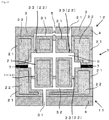
FIG. 1 shows a state of Example 1 characterized in that plural ventilation channels are provided in a cavity shape mold for resin injection molding. -
FIG. 2 shows a state of Example 2 characterized in that the degree of the sintered density gradually changes in a boundary region between a high-density shaped portion and a low-density shaped portion. -
FIG. 3 shows a typical embodiment of the present invention. -
FIG. 4 shows another embodiment in a core shape mold having a projection region inside of a peripheral wall. -
FIG. 5 shows an embodiment in a state in which the thickness of the secondary vent is reduced at the inside as compared with a surrounding region. - As shown in a typical embodiment of
FIG. 3 , in a basic constitution of the present invention, eachventilation channel 32 exists between one of primary vent or pluralprimary vents 31 and one of secondary vent or pluralsecondary vents 33, and forms a hollow state with situation surrounded by a peripheral wall having any one or both of the high-density shapedportion 21 and the low-density shapedportion 22. - In such a
hollow ventilation channel 32, a pressure loss is smaller compared with a state that gas passes through the low-density shapedportion 22 as in the case ofJP 2009233980 (A US 2011/045120 A1 ), so efficient ventilation can be achieved. - Furthermore, because a pressure in the case of an
ordinary ventilation channel 32 is equal, the pressure at the respectivesecondary vent 33 in theidentical ventilation channel 32 is equal regardless of the mold shape, and when pluralsecondary vents 33 are made equal in average wall thickness, the ventilation volume per unit area can be brought into an equal state. - Additionally, most of the
molds 1 for resin injection molding are, as shown inFIG. 3 , composed of both of a core shape mold 11 with projected region and acavity shape mold 12 without projected region, and when blowing is performed in theprimary vent 31 of one of the core shape mold 11 and thecavity shape mold 12 , discharge of gas is performed in theprimary vent 31 of the other of the core shape mold 11 and thecavity shape mold 12 , and when suction is performed in one of the core shape mold 11 and thecavity shape mold 12, entry of gas is performed in theprimary vent 31 of the other of the core shape mold 11 and thecavity shape mold 12. - However, of course, it is also possible to adopt such an embodiment that blowing is performed in the
primary vent 31 of one of the core shape mold 11 and thecavity shape mold 12 and suction is performed in theprimary vent 31 of the other of the core shape mold 11 and thecavity shape mold 12. - In
FIG. 3 , the entire peripheral wall is formed for theventilation channel 32 by the high-density shapedportion 21 in both of the core shape mold 11 and thecavity shape mold 12, and the peripheral wall can also be formed partially or entirely by the low-density shapedportion 22. - Because, even if the peripheral wall is formed partially or entirely by the low-density shaped
portion 22, gas inevitably passes through thesecondary vent 33 due to the cause that thesecondary vent 33 has a wall with thickness thinner than that of the shaping region, and a state of causing a pressure loss as is the case of the conventional technology does not arise in which gas passes through a shaping region formed by the low-density shapedportion 22, and so theresin molding portion 6 and theprimary vent 31 are connected communicatively. - However, in the case of a peripheral wall by the low-density shaped
portion 22, because of entry of gas into a partial region of the low-density shapedportion 22, the ventilation volume at thesecondary vent 33 decreases, and considering such a decreasing of the ventilation volume, it is preferable that the peripheral wall is entirely formed by the high-densityshaped portion 21 as is shown inFIG. 3 . - In a region of forming a wall portion that contacts the
resin molding portion 6, persons skilled in the arts can arbitrarily select which of the high-density shapedportion 21 as shown inFIG. 3 or the low-density shapedportion 22 as shown inFIG. 4 should be adopted. - However, taking into consideration the lifetime of the mold, the high-density shaped
portion 21 is preferably adopted for the region of forming the wall. - In the core shape mold 11, an embodiment is often adopted which is characterized, as shown in
FIG. 3 , in that thesecondary vent 33 is provided in any one or both of a gap between an inner wall portion and the projection region and a gap between projection regions. - However, as shown in
FIG. 4 , one secondary vent or pluralsecondary vents 33 can also be provided for the core shape mold 11 in the peripheral wall of the projection region. - In the
cavity shape mold 12, as shown inFIG. 3 , one secondary vent is or pluralsecondary vents 33 are often provided in a bottom portion surrounded by a peripheral wall. - Because gas can flow into the
resin molding portion 6 or flow out from theresin molding portion 6 almost equivalently through pluralsecondary vents 33. - However, in the case that a distance between peripheral walls is shorter than their height, an embodiment in which the
secondary vent 33 is provided inside of the peripheral wall may be adopted. - The
secondary vent 33 is required to satisfy both items that it can stand a pressure associated with resin molding and that gas outflows or inflows efficiently between thesecondary vent 33 and theresin molding portion 6. - The wall thickness of the
secondary vent 33 is dependent on a sintered density of the low-density shapedportion 22, and in most cases both requirements are satisfied by adopting the wall of thickness from 2mm to 5mm. -
FIG. 5 shows an embodiment of thesecondary vent 33 characterized in that a region at the inside thereof is formed gradually thin state compared with a surrounding region. - In the case of above embodiment, a pressure associated with resin molding is supported by the surrounding region of the
secondary vent 33 or a vicinity thereof, while gas can blow out or blow in efficiently thorough a thin-walled region in the center or a vicinity thereof. - Additionally, also in the embodiment shown in
FIG. 5 , by setting an average value of the wall thicknesses of thesecondary vent 33 to be in a range from 2mm to 5mm, both requirements of the wall standing the pressure associated with resin molding and sufficient gas outflowing or inflowing can be satisfied. - Example 1 is characterized in that, as shown in
FIG. 1 ,plural ventilation channels 32 are set up for communicating with eachprimary vent 31 and eachsecondary vent 33. - In Example 1 with such a characteristic, when the degree of necessary heating or cooling is different arisen by a difference of the shape of a resin molding region, ventilation volume can be controlled separately according to
respective ventilation channels 32, and so proper heating or cooling of a corresponding resin molding region can be achieved. - Example 2 is characterized in that, as shown in
FIG. 2 , the degree of the sintered density gradually changes in a boundary region between a high-density shapedportion 21 and a low-density shapedportion 22. - Example 2 with such a characteristic may be achieved by the process that in respectively molding the high-density shaped
portion 21 and the low-density shapedportion 22, gradually reducing the pressure of air to be injected into the low-density shapedportion 22 in the vicinity of a boundary of the high-density shapedportion 21 allows gradual change to molding of the high-density shapedportion 21. - As in
FIG. 3 ,FIG. 4 , andFIG. 5 , the high-density shapedportion 21 and the low-density shapedportion 22 must be separately molded when both shaped portions are clearly divided at a boundary, whereas continuous molding can be achieved in the case of Example 2. - In the basic construction of this invention, the ventilation channel is a hollow state with situation surrounded by the peripheral wall formed by any one or both of the high-density shaped portion and the low-density shaped portion, and the primary vent and the secondary vent are connected communicatively with each other, a gas blown or sucked by the primary vent can flow in or flow out through the secondary vent having a wall with thickness thinner than that of the shaping region and flow efficiently between the resin molding portion.
- So that in heating and cooling in the mold and ventilation with filling of resin, a pressure loss in conventional technology can be prevented.
- Further, as a pressure is equal in an identical ventilation channel, so the pressure at the secondary vent is equal regardless of the mold shape, and the ventilation volume per unit area can be brought into an equal state by setting an equal wall thickness for the secondary vent.
- Therefore, this invention can achieve heating and cooling with efficient and uniform ventilation, and can be widely applied to molds for resin injection molding.
-
- 1:
- Mold for resin injection molding
- 11:
- Core shape mold
- 12:
- Cavity shape mold
- 21:
- High-density shaped portion
- 22:
- Low-density shaped portion
- 31:
- Primary vent
- 32:
- Ventilation channel
- 33:
- Secondary vent
- 4:
- Base plate
- 5:
- Resin providing portion
- 6:
- Resin molding portion
- 7:
- Forming enclosed region portion
Claims (6)
- A mold for resin injection molding (1) having a shaping region formed by a low-density shaped portion (22) having a sintered density that allows a gas discharged with filling of a gas or resin blown or sucked in heating or cooling to pass therethrough and a high-density shaped portion (21) having a sintered density that does not allow the gas to pass therethrough,
wherein each ventilation channel (32) for gas exists between one of a primary vent (31) or plural primary vents (31) connecting communicatively with an exterior and plural secondary vents (33) connecting communicatively with a resin molding portion (6) at an inside with communicating both of the primary vent (31) and the plural secondary vents (33), and said each ventilation channel (32) forms a hollow state with a situation surrounded by a peripheral wall having any one or both of the high-density shaped portion (21) and the low-density shaped portion (22), and wherein the plural secondary vents (33) are formed only by the low-density shaped portion (22) in a state of having a wall with a thickness thinner than that of the shaping region, characterized in that the thickness of the plural secondary vents (33) is reduced at the inside as compared with a surrounding region. - The mold for resin injection molding (1) according to claim 1, in a core shape mold (11) with a projection region inside of a peripheral wall, wherein the secondary vents (33) are provided in any one or both of a gap between an inner wall portion and the projection region and a gap between the projection regions.
- The mold for resin injection molding (1) according to claim 1, in a cavity shape mold (12) without a projection region inside of a peripheral wall, wherein the secondary vents (33) are provided in a bottom portion surrounded by an inner wall portion.
- The mold for resin injection molding (1) according to claim 1, wherein an average thickness of each secondary vent (33) is from 2 mm to 5 mm.
- The mold for resin injection molding (1) according to any one of claims 1 - 4, wherein plural ventilation channels (32) are set up for connecting communicatively with each primary vent (31) and each secondary vent (33).
- The mold for resin injection molding (1) according to claims 1 - 5, wherein air pressures for blowing or suction are separately controlled according to respective ventilation channels (32).
Applications Claiming Priority (1)
| Application Number | Priority Date | Filing Date | Title |
|---|---|---|---|
| JP2015081079 | 2015-04-10 |
Publications (2)
| Publication Number | Publication Date |
|---|---|
| EP3078470A1 EP3078470A1 (en) | 2016-10-12 |
| EP3078470B1 true EP3078470B1 (en) | 2021-08-25 |
Family
ID=53525051
Family Applications (1)
| Application Number | Title | Priority Date | Filing Date |
|---|---|---|---|
| EP15173292.2A Active EP3078470B1 (en) | 2015-04-10 | 2015-06-23 | Mold for resin injection molding |
Country Status (7)
| Country | Link |
|---|---|
| US (1) | US9840033B2 (en) |
| EP (1) | EP3078470B1 (en) |
| JP (1) | JP6222783B2 (en) |
| KR (1) | KR101961518B1 (en) |
| CN (1) | CN106182606A (en) |
| CA (1) | CA2896000C (en) |
| ES (1) | ES2885811T3 (en) |
Families Citing this family (2)
| Publication number | Priority date | Publication date | Assignee | Title |
|---|---|---|---|---|
| CN106735212B (en) * | 2016-12-20 | 2018-05-08 | 东莞市康铭光电科技有限公司 | 3D printing integrated structure exhaust insert mold core method and exhaust insert mold core |
| CN121625385B (en) * | 2026-02-04 | 2026-05-22 | 佛山市蓝箭电子股份有限公司 | Injection molding method of flat plate frame for semiconductor packaging |
Family Cites Families (22)
| Publication number | Priority date | Publication date | Assignee | Title |
|---|---|---|---|---|
| US4165062A (en) * | 1978-01-13 | 1979-08-21 | California Injection Molding Co., Inc. | Mold with porous cavity vent |
| US4209731A (en) | 1978-11-30 | 1980-06-24 | Rca Corporation | Magnetic switching regulator for a deflection circuit |
| DE2948318A1 (en) * | 1979-11-30 | 1981-06-04 | Agfa-Gevaert Ag, 5090 Leverkusen | VENTILATION DEVICE FOR SHAPING TOOLS |
| JPS62128711A (en) * | 1985-11-30 | 1987-06-11 | Kojima Press Co Ltd | Molding tool having permeability |
| JPH01210323A (en) * | 1988-02-19 | 1989-08-23 | Honda Motor Co Ltd | Injection molding device |
| SE9100663L (en) * | 1991-03-05 | 1992-05-04 | Toolvac Engineering Ab | PROCEDURE FOR COOLING A FORM TOOL |
| JP3240023B2 (en) * | 1993-10-08 | 2001-12-17 | 新東工業株式会社 | Manufacturing method of durable air-permeable type |
| JP2973869B2 (en) | 1995-05-12 | 1999-11-08 | ブリヂストンスポーツ株式会社 | Golf ball manufacturing method and golf ball manufacturing mold |
| SE506728C2 (en) * | 1996-12-13 | 1998-02-02 | Aga Ab | Method and apparatus for cooling a condensing gas forming tool |
| JP2000202870A (en) * | 1999-01-13 | 2000-07-25 | Sekisui Chem Co Ltd | Injection mold |
| JP2002292692A (en) * | 2001-03-29 | 2002-10-09 | Canon Inc | Injection mold |
| DE10344901B4 (en) * | 2002-09-30 | 2006-09-07 | Matsushita Electric Works, Ltd., Kadoma | Method for producing a three-dimensional sintered product |
| JP3599056B2 (en) * | 2002-09-30 | 2004-12-08 | 松下電工株式会社 | Manufacturing method of three-dimensional shaped object |
| JP4544398B2 (en) * | 2004-02-06 | 2010-09-15 | トヨタ自動車株式会社 | Injection mold |
| JP4487636B2 (en) * | 2004-05-26 | 2010-06-23 | パナソニック電工株式会社 | Manufacturing method of three-dimensional shaped object |
| JP4821296B2 (en) | 2005-12-12 | 2011-11-24 | 日産自動車株式会社 | Mold structure for injection molding |
| JP5575374B2 (en) * | 2008-03-26 | 2014-08-20 | パナソニック株式会社 | Resin injection mold |
| JP5186316B2 (en) | 2008-09-09 | 2013-04-17 | パナソニック株式会社 | Manufacturing method of three-dimensional shaped object |
| JP5539347B2 (en) * | 2009-06-23 | 2014-07-02 | パナソニック株式会社 | Manufacturing method of three-dimensional shaped object and three-dimensional shaped object obtained therefrom |
| JP5653657B2 (en) * | 2010-06-09 | 2015-01-14 | パナソニック株式会社 | Method for producing three-dimensional shaped object, three-dimensional shaped object to be obtained, and method for producing molded product |
| WO2012124828A1 (en) * | 2011-03-17 | 2012-09-20 | パナソニック株式会社 | Production method for three-dimensionally shaped object and three-dimensionally shaped object |
| JP2014031018A (en) * | 2013-10-02 | 2014-02-20 | Panasonic Corp | Mold for resin injection molding, and injection molding method using mold |
-
2015
- 2015-06-05 CN CN201510303195.1A patent/CN106182606A/en active Pending
- 2015-06-17 JP JP2015121606A patent/JP6222783B2/en active Active
- 2015-06-23 ES ES15173292T patent/ES2885811T3/en active Active
- 2015-06-23 EP EP15173292.2A patent/EP3078470B1/en active Active
- 2015-06-25 KR KR1020150090702A patent/KR101961518B1/en active Active
- 2015-06-30 CA CA2896000A patent/CA2896000C/en active Active
- 2015-07-28 US US14/811,047 patent/US9840033B2/en active Active
Non-Patent Citations (1)
| Title |
|---|
| None * |
Also Published As
| Publication number | Publication date |
|---|---|
| CA2896000A1 (en) | 2016-10-10 |
| US20160297128A1 (en) | 2016-10-13 |
| JP2016199026A (en) | 2016-12-01 |
| US9840033B2 (en) | 2017-12-12 |
| ES2885811T3 (en) | 2021-12-15 |
| JP6222783B2 (en) | 2017-11-01 |
| KR20160121352A (en) | 2016-10-19 |
| EP3078470A1 (en) | 2016-10-12 |
| CN106182606A (en) | 2016-12-07 |
| CA2896000C (en) | 2018-05-01 |
| KR101961518B1 (en) | 2019-03-25 |
Similar Documents
| Publication | Publication Date | Title |
|---|---|---|
| CN108393458A (en) | Die ontology with integrated Quench | |
| EP4234209A3 (en) | Method for manufacturing resin container and blow molding method | |
| CN101992671A (en) | Ventilation nozzle | |
| US9840033B2 (en) | Mold for resin injection molding | |
| US10556375B2 (en) | Mould base provided with decompression channels opening on to a peripheral upper face | |
| WO2016135668A1 (en) | Blow mold for manufacturing containers made of thermoplastic material | |
| CN113210569B (en) | Ventilator for casting mould | |
| WO2018062034A1 (en) | Die, manufacturing method therefor, and molded body manufacturing method | |
| CN108172471B (en) | A high-load automotive relay with magnetic steel arc extinguishing | |
| JP2006289406A (en) | Casting equipment | |
| JP5336227B2 (en) | Manufacturing method of injection molded product and injection molding apparatus | |
| HK1228849A1 (en) | Mold for resin injection molding | |
| CN217346510U (en) | Improve mould structure of stranded gas defect | |
| CN211363269U (en) | Mould structure for cup-shaped product without thimble | |
| CN111469353B (en) | Mold device and molding system | |
| JP2015171718A (en) | Mold making mold | |
| US10967424B2 (en) | Casting mold and manufacturing method of cast part | |
| CN217412415U (en) | Casting device for machining deep hole castings | |
| CN110958922B (en) | Casting mold and method for manufacturing casting | |
| CN223762108U (en) | Cylinder end cover die casting mold | |
| CN220095220U (en) | Exhaust structure of mould | |
| KR101638955B1 (en) | Multiple hole type vent-plug and menufacturing method thereof | |
| CN213437022U (en) | 3D prints dysmorphism self-cleaning core vent | |
| JP2011178021A (en) | Injection molding mold, molding molded with the same, and molding method of molding using injection molding mold | |
| CN112074387B (en) | Molded element with diverging vent slots |
Legal Events
| Date | Code | Title | Description |
|---|---|---|---|
| PUAI | Public reference made under article 153(3) epc to a published international application that has entered the european phase |
Free format text: ORIGINAL CODE: 0009012 |
|
| AK | Designated contracting states |
Kind code of ref document: A1 Designated state(s): AL AT BE BG CH CY CZ DE DK EE ES FI FR GB GR HR HU IE IS IT LI LT LU LV MC MK MT NL NO PL PT RO RS SE SI SK SM TR |
|
| AX | Request for extension of the european patent |
Extension state: BA ME |
|
| STAA | Information on the status of an ep patent application or granted ep patent |
Free format text: STATUS: REQUEST FOR EXAMINATION WAS MADE |
|
| 17P | Request for examination filed |
Effective date: 20170410 |
|
| RBV | Designated contracting states (corrected) |
Designated state(s): AL AT BE BG CH CY CZ DE DK EE ES FI FR GB GR HR HU IE IS IT LI LT LU LV MC MK MT NL NO PL PT RO RS SE SI SK SM TR |
|
| RAP1 | Party data changed (applicant data changed or rights of an application transferred) |
Owner name: MATSUURA MACHINERY CORPORATION |
|
| STAA | Information on the status of an ep patent application or granted ep patent |
Free format text: STATUS: EXAMINATION IS IN PROGRESS |
|
| 17Q | First examination report despatched |
Effective date: 20190911 |
|
| GRAP | Despatch of communication of intention to grant a patent |
Free format text: ORIGINAL CODE: EPIDOSNIGR1 |
|
| STAA | Information on the status of an ep patent application or granted ep patent |
Free format text: STATUS: GRANT OF PATENT IS INTENDED |
|
| RIC1 | Information provided on ipc code assigned before grant |
Ipc: B29C 45/72 20060101ALI20210511BHEP Ipc: B29C 33/38 20060101ALI20210511BHEP Ipc: B22F 5/00 20060101ALI20210511BHEP Ipc: B29C 45/73 20060101ALI20210511BHEP Ipc: B29C 33/10 20060101ALI20210511BHEP Ipc: B29C 45/34 20060101ALI20210511BHEP Ipc: B22F 3/105 20060101ALI20210511BHEP Ipc: B29C 33/56 20060101AFI20210511BHEP |
|
| INTG | Intention to grant announced |
Effective date: 20210531 |
|
| GRAS | Grant fee paid |
Free format text: ORIGINAL CODE: EPIDOSNIGR3 |
|
| GRAA | (expected) grant |
Free format text: ORIGINAL CODE: 0009210 |
|
| STAA | Information on the status of an ep patent application or granted ep patent |
Free format text: STATUS: THE PATENT HAS BEEN GRANTED |
|
| AK | Designated contracting states |
Kind code of ref document: B1 Designated state(s): AL AT BE BG CH CY CZ DE DK EE ES FI FR GB GR HR HU IE IS IT LI LT LU LV MC MK MT NL NO PL PT RO RS SE SI SK SM TR |
|
| REG | Reference to a national code |
Ref country code: CH Ref legal event code: EP |
|
| REG | Reference to a national code |
Ref country code: DE Ref legal event code: R096 Ref document number: 602015072542 Country of ref document: DE |
|
| REG | Reference to a national code |
Ref country code: IE Ref legal event code: FG4D Ref country code: AT Ref legal event code: REF Ref document number: 1423327 Country of ref document: AT Kind code of ref document: T Effective date: 20210915 |
|
| REG | Reference to a national code |
Ref country code: LT Ref legal event code: MG9D |
|
| REG | Reference to a national code |
Ref country code: ES Ref legal event code: FG2A Ref document number: 2885811 Country of ref document: ES Kind code of ref document: T3 Effective date: 20211215 |
|
| REG | Reference to a national code |
Ref country code: NL Ref legal event code: MP Effective date: 20210825 |
|
| REG | Reference to a national code |
Ref country code: AT Ref legal event code: MK05 Ref document number: 1423327 Country of ref document: AT Kind code of ref document: T Effective date: 20210825 |
|
| PG25 | Lapsed in a contracting state [announced via postgrant information from national office to epo] |
Ref country code: RS Free format text: LAPSE BECAUSE OF FAILURE TO SUBMIT A TRANSLATION OF THE DESCRIPTION OR TO PAY THE FEE WITHIN THE PRESCRIBED TIME-LIMIT Effective date: 20210825 Ref country code: SE Free format text: LAPSE BECAUSE OF FAILURE TO SUBMIT A TRANSLATION OF THE DESCRIPTION OR TO PAY THE FEE WITHIN THE PRESCRIBED TIME-LIMIT Effective date: 20210825 Ref country code: HR Free format text: LAPSE BECAUSE OF FAILURE TO SUBMIT A TRANSLATION OF THE DESCRIPTION OR TO PAY THE FEE WITHIN THE PRESCRIBED TIME-LIMIT Effective date: 20210825 Ref country code: BG Free format text: LAPSE BECAUSE OF FAILURE TO SUBMIT A TRANSLATION OF THE DESCRIPTION OR TO PAY THE FEE WITHIN THE PRESCRIBED TIME-LIMIT Effective date: 20211125 Ref country code: AT Free format text: LAPSE BECAUSE OF FAILURE TO SUBMIT A TRANSLATION OF THE DESCRIPTION OR TO PAY THE FEE WITHIN THE PRESCRIBED TIME-LIMIT Effective date: 20210825 Ref country code: LT Free format text: LAPSE BECAUSE OF FAILURE TO SUBMIT A TRANSLATION OF THE DESCRIPTION OR TO PAY THE FEE WITHIN THE PRESCRIBED TIME-LIMIT Effective date: 20210825 Ref country code: FI Free format text: LAPSE BECAUSE OF FAILURE TO SUBMIT A TRANSLATION OF THE DESCRIPTION OR TO PAY THE FEE WITHIN THE PRESCRIBED TIME-LIMIT Effective date: 20210825 Ref country code: PT Free format text: LAPSE BECAUSE OF FAILURE TO SUBMIT A TRANSLATION OF THE DESCRIPTION OR TO PAY THE FEE WITHIN THE PRESCRIBED TIME-LIMIT Effective date: 20211227 Ref country code: NO Free format text: LAPSE BECAUSE OF FAILURE TO SUBMIT A TRANSLATION OF THE DESCRIPTION OR TO PAY THE FEE WITHIN THE PRESCRIBED TIME-LIMIT Effective date: 20211125 |
|
| PG25 | Lapsed in a contracting state [announced via postgrant information from national office to epo] |
Ref country code: PL Free format text: LAPSE BECAUSE OF FAILURE TO SUBMIT A TRANSLATION OF THE DESCRIPTION OR TO PAY THE FEE WITHIN THE PRESCRIBED TIME-LIMIT Effective date: 20210825 Ref country code: LV Free format text: LAPSE BECAUSE OF FAILURE TO SUBMIT A TRANSLATION OF THE DESCRIPTION OR TO PAY THE FEE WITHIN THE PRESCRIBED TIME-LIMIT Effective date: 20210825 Ref country code: GR Free format text: LAPSE BECAUSE OF FAILURE TO SUBMIT A TRANSLATION OF THE DESCRIPTION OR TO PAY THE FEE WITHIN THE PRESCRIBED TIME-LIMIT Effective date: 20211126 |
|
| PG25 | Lapsed in a contracting state [announced via postgrant information from national office to epo] |
Ref country code: NL Free format text: LAPSE BECAUSE OF FAILURE TO SUBMIT A TRANSLATION OF THE DESCRIPTION OR TO PAY THE FEE WITHIN THE PRESCRIBED TIME-LIMIT Effective date: 20210825 |
|
| PG25 | Lapsed in a contracting state [announced via postgrant information from national office to epo] |
Ref country code: DK Free format text: LAPSE BECAUSE OF FAILURE TO SUBMIT A TRANSLATION OF THE DESCRIPTION OR TO PAY THE FEE WITHIN THE PRESCRIBED TIME-LIMIT Effective date: 20210825 |
|
| REG | Reference to a national code |
Ref country code: DE Ref legal event code: R097 Ref document number: 602015072542 Country of ref document: DE |
|
| PG25 | Lapsed in a contracting state [announced via postgrant information from national office to epo] |
Ref country code: SM Free format text: LAPSE BECAUSE OF FAILURE TO SUBMIT A TRANSLATION OF THE DESCRIPTION OR TO PAY THE FEE WITHIN THE PRESCRIBED TIME-LIMIT Effective date: 20210825 Ref country code: SK Free format text: LAPSE BECAUSE OF FAILURE TO SUBMIT A TRANSLATION OF THE DESCRIPTION OR TO PAY THE FEE WITHIN THE PRESCRIBED TIME-LIMIT Effective date: 20210825 Ref country code: RO Free format text: LAPSE BECAUSE OF FAILURE TO SUBMIT A TRANSLATION OF THE DESCRIPTION OR TO PAY THE FEE WITHIN THE PRESCRIBED TIME-LIMIT Effective date: 20210825 Ref country code: EE Free format text: LAPSE BECAUSE OF FAILURE TO SUBMIT A TRANSLATION OF THE DESCRIPTION OR TO PAY THE FEE WITHIN THE PRESCRIBED TIME-LIMIT Effective date: 20210825 Ref country code: CZ Free format text: LAPSE BECAUSE OF FAILURE TO SUBMIT A TRANSLATION OF THE DESCRIPTION OR TO PAY THE FEE WITHIN THE PRESCRIBED TIME-LIMIT Effective date: 20210825 Ref country code: AL Free format text: LAPSE BECAUSE OF FAILURE TO SUBMIT A TRANSLATION OF THE DESCRIPTION OR TO PAY THE FEE WITHIN THE PRESCRIBED TIME-LIMIT Effective date: 20210825 |
|
| PLBE | No opposition filed within time limit |
Free format text: ORIGINAL CODE: 0009261 |
|
| STAA | Information on the status of an ep patent application or granted ep patent |
Free format text: STATUS: NO OPPOSITION FILED WITHIN TIME LIMIT |
|
| 26N | No opposition filed |
Effective date: 20220527 |
|
| PG25 | Lapsed in a contracting state [announced via postgrant information from national office to epo] |
Ref country code: SI Free format text: LAPSE BECAUSE OF FAILURE TO SUBMIT A TRANSLATION OF THE DESCRIPTION OR TO PAY THE FEE WITHIN THE PRESCRIBED TIME-LIMIT Effective date: 20210825 |
|
| PG25 | Lapsed in a contracting state [announced via postgrant information from national office to epo] |
Ref country code: MC Free format text: LAPSE BECAUSE OF FAILURE TO SUBMIT A TRANSLATION OF THE DESCRIPTION OR TO PAY THE FEE WITHIN THE PRESCRIBED TIME-LIMIT Effective date: 20210825 |
|
| REG | Reference to a national code |
Ref country code: BE Ref legal event code: MM Effective date: 20220630 |
|
| PG25 | Lapsed in a contracting state [announced via postgrant information from national office to epo] |
Ref country code: LU Free format text: LAPSE BECAUSE OF NON-PAYMENT OF DUE FEES Effective date: 20220623 Ref country code: IE Free format text: LAPSE BECAUSE OF NON-PAYMENT OF DUE FEES Effective date: 20220623 |
|
| PG25 | Lapsed in a contracting state [announced via postgrant information from national office to epo] |
Ref country code: BE Free format text: LAPSE BECAUSE OF NON-PAYMENT OF DUE FEES Effective date: 20220630 |
|
| PG25 | Lapsed in a contracting state [announced via postgrant information from national office to epo] |
Ref country code: HU Free format text: LAPSE BECAUSE OF FAILURE TO SUBMIT A TRANSLATION OF THE DESCRIPTION OR TO PAY THE FEE WITHIN THE PRESCRIBED TIME-LIMIT; INVALID AB INITIO Effective date: 20150623 |
|
| PG25 | Lapsed in a contracting state [announced via postgrant information from national office to epo] |
Ref country code: MK Free format text: LAPSE BECAUSE OF FAILURE TO SUBMIT A TRANSLATION OF THE DESCRIPTION OR TO PAY THE FEE WITHIN THE PRESCRIBED TIME-LIMIT Effective date: 20210825 Ref country code: CY Free format text: LAPSE BECAUSE OF FAILURE TO SUBMIT A TRANSLATION OF THE DESCRIPTION OR TO PAY THE FEE WITHIN THE PRESCRIBED TIME-LIMIT Effective date: 20210825 |
|
| PG25 | Lapsed in a contracting state [announced via postgrant information from national office to epo] |
Ref country code: TR Free format text: LAPSE BECAUSE OF FAILURE TO SUBMIT A TRANSLATION OF THE DESCRIPTION OR TO PAY THE FEE WITHIN THE PRESCRIBED TIME-LIMIT Effective date: 20210825 |
|
| PG25 | Lapsed in a contracting state [announced via postgrant information from national office to epo] |
Ref country code: MT Free format text: LAPSE BECAUSE OF FAILURE TO SUBMIT A TRANSLATION OF THE DESCRIPTION OR TO PAY THE FEE WITHIN THE PRESCRIBED TIME-LIMIT Effective date: 20210825 |
|
| PGFP | Annual fee paid to national office [announced via postgrant information from national office to epo] |
Ref country code: CH Payment date: 20240701 Year of fee payment: 10 |
|
| PGFP | Annual fee paid to national office [announced via postgrant information from national office to epo] |
Ref country code: ES Payment date: 20250701 Year of fee payment: 11 |
|
| REG | Reference to a national code |
Ref country code: CH Ref legal event code: H13 Free format text: ST27 STATUS EVENT CODE: U-0-0-H10-H13 (AS PROVIDED BY THE NATIONAL OFFICE) Effective date: 20260127 |
|
| PG25 | Lapsed in a contracting state [announced via postgrant information from national office to epo] |
Ref country code: CH Free format text: LAPSE BECAUSE OF NON-PAYMENT OF DUE FEES Effective date: 20250630 |
|
| PGFP | Annual fee paid to national office [announced via postgrant information from national office to epo] |
Ref country code: GB Payment date: 20260624 Year of fee payment: 12 |
|
| PGFP | Annual fee paid to national office [announced via postgrant information from national office to epo] |
Ref country code: IT Payment date: 20260626 Year of fee payment: 12 |
|
| PGFP | Annual fee paid to national office [announced via postgrant information from national office to epo] |
Ref country code: DE Payment date: 20260528 Year of fee payment: 12 |
|
| PGFP | Annual fee paid to national office [announced via postgrant information from national office to epo] |
Ref country code: FR Payment date: 20260629 Year of fee payment: 12 |