EP3078392B1 - Filter structure - Google Patents
Filter structure Download PDFInfo
- Publication number
- EP3078392B1 EP3078392B1 EP14873133.4A EP14873133A EP3078392B1 EP 3078392 B1 EP3078392 B1 EP 3078392B1 EP 14873133 A EP14873133 A EP 14873133A EP 3078392 B1 EP3078392 B1 EP 3078392B1
- Authority
- EP
- European Patent Office
- Prior art keywords
- blower
- bag
- filter
- gas
- assistance device
- Prior art date
- Legal status (The legal status is an assumption and is not a legal conclusion. Google has not performed a legal analysis and makes no representation as to the accuracy of the status listed.)
- Active
Links
- 230000000241 respiratory effect Effects 0.000 claims description 50
- 239000000463 material Substances 0.000 claims description 11
- 210000000056 organ Anatomy 0.000 claims description 8
- 238000012423 maintenance Methods 0.000 description 12
- 210000003437 trachea Anatomy 0.000 description 8
- 230000000694 effects Effects 0.000 description 4
- 241000894006 Bacteria Species 0.000 description 3
- 102100025579 Calmodulin-2 Human genes 0.000 description 3
- 101001077352 Homo sapiens Calcium/calmodulin-dependent protein kinase type II subunit beta Proteins 0.000 description 3
- 241000700605 Viruses Species 0.000 description 3
- 230000029058 respiratory gaseous exchange Effects 0.000 description 3
- 101100118004 Arabidopsis thaliana EBP1 gene Proteins 0.000 description 2
- 101150052583 CALM1 gene Proteins 0.000 description 2
- 102100025580 Calmodulin-1 Human genes 0.000 description 2
- 101100459256 Cyprinus carpio myca gene Proteins 0.000 description 2
- 208000019417 Respiration disease Diseases 0.000 description 2
- 101150091339 cam-1 gene Proteins 0.000 description 2
- 230000008859 change Effects 0.000 description 2
- 239000003086 colorant Substances 0.000 description 2
- 238000004040 coloring Methods 0.000 description 2
- 230000000593 degrading effect Effects 0.000 description 2
- 238000004519 manufacturing process Methods 0.000 description 2
- 238000000059 patterning Methods 0.000 description 2
- 208000008784 apnea Diseases 0.000 description 1
- 238000011109 contamination Methods 0.000 description 1
- 239000000428 dust Substances 0.000 description 1
- 239000004744 fabric Substances 0.000 description 1
- 230000003434 inspiratory effect Effects 0.000 description 1
- 239000004973 liquid crystal related substance Substances 0.000 description 1
- 210000003205 muscle Anatomy 0.000 description 1
- 230000035699 permeability Effects 0.000 description 1
- 230000009467 reduction Effects 0.000 description 1
- 230000002787 reinforcement Effects 0.000 description 1
- 230000004044 response Effects 0.000 description 1
- 201000002859 sleep apnea Diseases 0.000 description 1
- 210000001584 soft palate Anatomy 0.000 description 1
Images
Classifications
-
- A—HUMAN NECESSITIES
- A61—MEDICAL OR VETERINARY SCIENCE; HYGIENE
- A61M—DEVICES FOR INTRODUCING MEDIA INTO, OR ONTO, THE BODY; DEVICES FOR TRANSDUCING BODY MEDIA OR FOR TAKING MEDIA FROM THE BODY; DEVICES FOR PRODUCING OR ENDING SLEEP OR STUPOR
- A61M16/00—Devices for influencing the respiratory system of patients by gas treatment, e.g. mouth-to-mouth respiration; Tracheal tubes
- A61M16/10—Preparation of respiratory gases or vapours
- A61M16/105—Filters
- A61M16/1055—Filters bacterial
-
- A—HUMAN NECESSITIES
- A61—MEDICAL OR VETERINARY SCIENCE; HYGIENE
- A61M—DEVICES FOR INTRODUCING MEDIA INTO, OR ONTO, THE BODY; DEVICES FOR TRANSDUCING BODY MEDIA OR FOR TAKING MEDIA FROM THE BODY; DEVICES FOR PRODUCING OR ENDING SLEEP OR STUPOR
- A61M16/00—Devices for influencing the respiratory system of patients by gas treatment, e.g. mouth-to-mouth respiration; Tracheal tubes
- A61M16/0057—Pumps therefor
- A61M16/0066—Blowers or centrifugal pumps
-
- A—HUMAN NECESSITIES
- A61—MEDICAL OR VETERINARY SCIENCE; HYGIENE
- A61M—DEVICES FOR INTRODUCING MEDIA INTO, OR ONTO, THE BODY; DEVICES FOR TRANSDUCING BODY MEDIA OR FOR TAKING MEDIA FROM THE BODY; DEVICES FOR PRODUCING OR ENDING SLEEP OR STUPOR
- A61M16/00—Devices for influencing the respiratory system of patients by gas treatment, e.g. mouth-to-mouth respiration; Tracheal tubes
- A61M16/06—Respiratory or anaesthetic masks
-
- A—HUMAN NECESSITIES
- A61—MEDICAL OR VETERINARY SCIENCE; HYGIENE
- A61M—DEVICES FOR INTRODUCING MEDIA INTO, OR ONTO, THE BODY; DEVICES FOR TRANSDUCING BODY MEDIA OR FOR TAKING MEDIA FROM THE BODY; DEVICES FOR PRODUCING OR ENDING SLEEP OR STUPOR
- A61M16/00—Devices for influencing the respiratory system of patients by gas treatment, e.g. mouth-to-mouth respiration; Tracheal tubes
- A61M16/10—Preparation of respiratory gases or vapours
- A61M16/105—Filters
- A61M16/106—Filters in a path
- A61M16/107—Filters in a path in the inspiratory path
-
- F—MECHANICAL ENGINEERING; LIGHTING; HEATING; WEAPONS; BLASTING
- F04—POSITIVE - DISPLACEMENT MACHINES FOR LIQUIDS; PUMPS FOR LIQUIDS OR ELASTIC FLUIDS
- F04D—NON-POSITIVE-DISPLACEMENT PUMPS
- F04D17/00—Radial-flow pumps, e.g. centrifugal pumps; Helico-centrifugal pumps
- F04D17/08—Centrifugal pumps
- F04D17/16—Centrifugal pumps for displacing without appreciable compression
-
- F—MECHANICAL ENGINEERING; LIGHTING; HEATING; WEAPONS; BLASTING
- F04—POSITIVE - DISPLACEMENT MACHINES FOR LIQUIDS; PUMPS FOR LIQUIDS OR ELASTIC FLUIDS
- F04D—NON-POSITIVE-DISPLACEMENT PUMPS
- F04D29/00—Details, component parts, or accessories
- F04D29/60—Mounting; Assembling; Disassembling
- F04D29/601—Mounting; Assembling; Disassembling specially adapted for elastic fluid pumps
-
- F—MECHANICAL ENGINEERING; LIGHTING; HEATING; WEAPONS; BLASTING
- F04—POSITIVE - DISPLACEMENT MACHINES FOR LIQUIDS; PUMPS FOR LIQUIDS OR ELASTIC FLUIDS
- F04D—NON-POSITIVE-DISPLACEMENT PUMPS
- F04D29/00—Details, component parts, or accessories
- F04D29/70—Suction grids; Strainers; Dust separation; Cleaning
- F04D29/701—Suction grids; Strainers; Dust separation; Cleaning especially adapted for elastic fluid pumps
- F04D29/703—Suction grids; Strainers; Dust separation; Cleaning especially adapted for elastic fluid pumps specially for fans, e.g. fan guards
-
- A—HUMAN NECESSITIES
- A61—MEDICAL OR VETERINARY SCIENCE; HYGIENE
- A61M—DEVICES FOR INTRODUCING MEDIA INTO, OR ONTO, THE BODY; DEVICES FOR TRANSDUCING BODY MEDIA OR FOR TAKING MEDIA FROM THE BODY; DEVICES FOR PRODUCING OR ENDING SLEEP OR STUPOR
- A61M2205/00—General characteristics of the apparatus
- A61M2205/75—General characteristics of the apparatus with filters
- A61M2205/7509—General characteristics of the apparatus with filters for virus
-
- A—HUMAN NECESSITIES
- A61—MEDICAL OR VETERINARY SCIENCE; HYGIENE
- A61M—DEVICES FOR INTRODUCING MEDIA INTO, OR ONTO, THE BODY; DEVICES FOR TRANSDUCING BODY MEDIA OR FOR TAKING MEDIA FROM THE BODY; DEVICES FOR PRODUCING OR ENDING SLEEP OR STUPOR
- A61M2205/00—General characteristics of the apparatus
- A61M2205/75—General characteristics of the apparatus with filters
- A61M2205/7518—General characteristics of the apparatus with filters bacterial
-
- A—HUMAN NECESSITIES
- A61—MEDICAL OR VETERINARY SCIENCE; HYGIENE
- A61M—DEVICES FOR INTRODUCING MEDIA INTO, OR ONTO, THE BODY; DEVICES FOR TRANSDUCING BODY MEDIA OR FOR TAKING MEDIA FROM THE BODY; DEVICES FOR PRODUCING OR ENDING SLEEP OR STUPOR
- A61M2205/00—General characteristics of the apparatus
- A61M2205/75—General characteristics of the apparatus with filters
- A61M2205/7536—General characteristics of the apparatus with filters allowing gas passage, but preventing liquid passage, e.g. liquophobic, hydrophobic, water-repellent membranes
-
- A—HUMAN NECESSITIES
- A61—MEDICAL OR VETERINARY SCIENCE; HYGIENE
- A61M—DEVICES FOR INTRODUCING MEDIA INTO, OR ONTO, THE BODY; DEVICES FOR TRANSDUCING BODY MEDIA OR FOR TAKING MEDIA FROM THE BODY; DEVICES FOR PRODUCING OR ENDING SLEEP OR STUPOR
- A61M2205/00—General characteristics of the apparatus
- A61M2205/75—General characteristics of the apparatus with filters
- A61M2205/7545—General characteristics of the apparatus with filters for solid matter, e.g. microaggregates
Definitions
- the present invention relates to a filter structure for a blower.
- apnea is caused by a root of a tongue and a soft palate moving down due to flaccid muscles during sleep and clogging a trachea.
- Patients with this respiration disorder use respiratory assistance devices, which prevent the clogging by the application of a positive pressure to the trachea (refer to Japanese Patent Application Laid-Open JP 2013-071004 A ).
- a respiration device is known from document WO 2013/133889 A1 .
- Further respiration devices are known from document WO 2012/174602 A1 and document WO 2011/022779 A1 , wherein WO2012/174602 discloses a device according to the preamble of claim 1.
- the respiration assistance devices are provided with a blower having a gas suction opening.
- the blower compresses gas such as air taken from the gas suction opening, and supplies the compressed gas to the trachea of the patient.
- a filter is attached to the gas suction opening in order to prevent the contamination of bacteria, viruses, and dust into inspiratory gas.
- the filter is easily clogged.
- the clogged filter degrades the performance of the blower, and interferes with the supply of a sufficient amount of gas to the trachea of the patient, thus failing to prevent the clogging of the trachea. That is to say, the apnea may occur even with a treatment using the respiratory assistance device.
- maintenance including filter replacement is required on a regular basis. Depending on a usage environment, the frequency of the filter maintenance is increased, thus expending much effort.
- the present invention has been made in consideration of the above problem, and an object thereof is to provide a filter structure that reduces effort required for maintenance of a filter.
- the present invention it is possible to significantly increase the size of a filter.
- a sufficient amount of gas can be supplied to the trachea of a user without degrading the performance of the blower.
- the partial clogging of the filter does not require maintenance of the filter. In other words, it is possible to reduce effort for the maintenance of the filter.
- the bag made of the filter material covers the entire device, the device is protected from bacteria, viruses, and dirt.
- Patterning or coloring the exterior of the bag serves to improve a bag design. As a result, it is possible to get rid of a negative image as a medical appliance. This brings the user an easy feeling about use. Thus, a product's value rises.
- the exterior of the bag can be easily patterned or colored by printing on the nonwoven paper without a cost increase. That is to say, a bag design is easily improved.
- the filter structure described in the above (1) to (4) of the present invention has the superior effect of reducing effort for maintenance of the filter.
- a respiratory assistance device according to the present invention will be hereinafter described in detail with reference to the drawings.
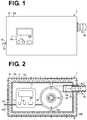
- FIG. 1 is an external view of the respiratory assistance device 1.
- FIG. 2 is a schematic view illustrating the inside of the respiratory assistance device 1. Note that, part of the structure is appropriately omitted in each of these and subsequent drawings to simplify the drawings.
- the respiratory assistance device 1 illustrated in FIGs. 1 and 2 is used by a patient (user) of a respiration disorder to generate a positive pressure in his/her trachea. More specifically, the respiratory assistance device 1 includes a blower 10, a control box 11, an air feed pipe 12, a power cord 13, a connection cord 14, a housing 15, a bag 16, a chamber forming member 17, O-rings 18 and 19, and the like.
- the blower 10 is contained in the housing 15.
- the blower 10 is controlled by a control unit (not shown) in the control box 11. That is, the blower 10 is operated under the control of the control unit, and the control unit manages an operation state thereof.
- the blower 10 has a gas suction opening 10a, an air feed opening 10b, and the like.
- the blower 10 compresses gas such as air taken through the gas suction opening 10a, and supplies the compressed gas to respiratory organs of the patient through the air feed opening 10b and the like.
- the blower 10 has a well-known structure and hence the detailed description thereof will be omitted using, for example, Japanese Patent No. 5211302 as the reference.
- the control box 11 is contained in the housing 15.
- the control box 11 is provided with a monitor 11a, buttons 11b, and the like.
- the control box 11 contains the control unit (not shown).
- the monitor 11a is, for example, a liquid crystal display to display an operation state of the respiratory assistance device 1.
- the buttons 11b function as a man-machine interface by the operation of which predetermined signals are inputted to the control unit.
- the control unit is operated by power supplied from the power cord 13.
- the control unit performs various controls in response to the predetermined signals inputted by the operation of the buttons 11b.
- the control unit includes a CPU, a RAM, a ROM, and the like.
- the CPU is a so-called central processing unit, which executes various programs to implement various functions.
- the RAM is used as work space for the CPU.
- the ROM stores a basic OS and the programs executed by the CPU.
- the air feed pipe 12 is provided so as to penetrate the housing 15 and the bag 16.
- the air feed pipe 12 is connected to the air feed opening 10b of the blower 10 at its proximal end, and connected to a duct 20 in a detachable manner at its distal end.
- the air feed pipe 12 leads the gas fed from the air feed opening 10b of the blower 10 into the duct 20.
- the power cord 13 extends from the control box 11 so as to penetrate the housing 15 and the bag 16. Through the power cord 13, the control unit (not shown) in the control box 11 is powered from outside.
- connection cord 14 electrically connects between the control unit (not shown) in the control box 11 and a motor (not shown) in the blower 10. Through the connection cord 14, an electric signal is sent from the control unit to the motor.
- the housing 15 contains the blower 10, the control box 11, the air feed pipe 12, and the like.
- the housing 15 is formed with air passage openings 15a and the like.
- the air passage openings 15a are formed for the purpose of taking the air, which is to be taken into the blower 10, from the outside of the housing 15 to the inside thereof.
- a plurality of projections 17a, which constitute the chamber forming member 17, are attached to the outside of the housing 15.
- the bag 16 for covering the housing 15 is made of a nonwoven paper 16a having an opened window (with no reference numeral), and a transparent film 16b for closing the window formed in the nonwoven paper 16a.
- the nonwoven paper 16a functions as a filter.
- a hole 16a1 is formed to pass the air feed pipe 12, and a hole 16a2 is formed to pass the power cord 13.
- the O-rings 18 and 19 are fitted into the holes 16a1 and 16a2, respectively.
- the bag 16 is formed by closing an opening (not shown) and replaceable.
- the opening of the bag 16 is openable and reclosable.
- At least part of the bag 16 may be formed of the nonwoven paper 16a.
- the exterior of the bag 16 may be patterned or colored.
- the bag 16 does not pass gas except for the portion of the nonwoven paper 16a.
- the chamber forming member 17 is present between the housing 15 and the bag 16, and forms a chamber CAM between each air passage opening 15a of the housing 15 and the nonwoven paper 16a constituting the bag 16.
- the chamber forming member 17 is constituted by the plurality of projections 17a attached to the outside of the housing 15.
- the O-rings 18 and 19 are fitted on the holes 16a1 and 16a2 formed in the nonwoven paper 16a, respectively.
- the air feed pipe 12 is fitted into the O-ring 18.
- the power cord 13 is fitted into the O-ring 19.
- the duct 20 leads the gas fed through the air feed pipe 12 to the respiratory organs of the patient.
- gas outside the bag 16 is taken into the chamber CAM formed inside the bag 16 through the nonwoven paper 16a.
- the gas taken into the chamber CAM is taken into the housing 15 through the air passage openings 15a.
- the gas taken into the housing 15 is taken into the blower 10 through the gas suction opening 10a.
- the gas taken into the blower 10 is compressed and supplied to the respiratory organs of the patient through the air feed opening 10b, the air feed pipe 12, the duct 20, and the like.
- the filter structure that the respiratory assistance device 1 adopts allows a significant increase in the area of the filter.
- a sufficient amount of gas can be supplied to the trachea of the patient without degrading the performance of the blower 10. Therefore, even if part of the nonwoven paper 16a is clogged, the nonwoven paper does not require maintenance. In other words, it is possible to reduce effort for the maintenance of the nonwoven paper 16a.
- the bag 16 made of the nonwoven paper 16a covers the entire device, the device can be protected from bacteria, viruses, and dirt.
- Patterning or coloring the exterior of the bag 16 serves to improve a bag design. As a result, it is possible to get rid of a negative image as a medical appliance. This brings the patient an easy feeling about use. Thus, a product's value rises.
- the bag 16 is formed by closing the opening (not shown) and replaceable, the nonwoven paper 16a, which functions as the filter, can be easily replaced. As a result, it is possible to further reduce the effort for the maintenance of the nonwoven paper 16a.
- the nonwoven paper 16a which functions as the filter, can be detached and cleaned. As a result, it is possible to further reduce the effort for the maintenance of the nonwoven paper 16a.
- nonwoven paper 16a as the filter allows low manufacturing costs.
- the exterior of the bag 16 is easily patterned or colored without a cost increase by printing on the nonwoven paper 16a. That is to say, a bag design is easily improved.
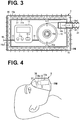
- FIG. 3 is a schematic view illustrating the inside of the respiratory assistance device 2. Note that, only characteristic portions of the respiratory Note that, only characteristic portions of the respiratory assistance device 2 will be described here, though a description about the same structures, effects, and advantages as the respiratory assistance device 1 will be appropriately omitted. Also in each of embodiments described below, only characteristic portions will be described, though a description about the same structures, effects, and advantages as the other respiratory assistance device will be appropriately omitted.
- the respiratory assistance device 2 illustrated in FIG. 3 is different from the respiratory assistance device 1 according to the first embodiment in terms of providing a chamber forming member 27, instead of the chamber forming member 17.
- the chamber forming member 27 is constituted by a plurality of projections 27a attached to the inside of the bag 16.
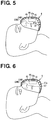
- FIG. 4 is a schematic view illustrating the inside of the respiratory assistance device 3.
- blower 10 is provided with a blower 10, a control box (not shown), a mask 36, prongs 37, and the like.
- the blower 10 is attached to the inside of the mask 36. That is, the blower 10 is disposed in a chamber CAM formed between the mask 36 and a face of a patient. A gas suction opening 10a of the blower 10 takes in gas present in the chamber CAM.
- the control box (not shown) is provided outside the mask 36 in an independent manner.
- a control unit in the control box is electrically connected to a motor (not shown) of the blower 10 through a connection cord (not shown).
- the mask 36 is fixed on the face of the patient using a fixture such as a band (not shown).
- the mask 36 covers a mouth or nose of the patient so as to form the chamber CAM between the face of the patient and the mask 36.
- the mask 36 is made of a filter such as a nonwoven paper. It is noted that at least part of the mask 36 may be formed of the filter.
- the mask 36 may be appropriately provided with a frame or the like for reinforcement.
- the mask 36 does not pass gas except for the portion of the filter.
- An air feed opening 10b of the blower 10 is connected to proximal ends of the prongs 37, and distal ends of the prongs proximal ends of the prongs 37, and distal ends of the prongs 37 are inserted into the nose of the patient.
- the prongs 37 lead the gas fed from the air feed opening 10b of the blower 10 to the nose of the patient.
- the respiratory assistance device 3 may be provided with a chamber forming member that is disposed between the blower 10 and the mask 36 to maintain the chamber CAM between the gas suction opening 10a of the blower 10 and a filter portion of the mask 36.
- the chamber forming member may be provided outside the blower 10 or inside the mask 36.
- gas outside the mask 36 is taken into the chamber CAM formed inside the mask 36 through the mask 36.
- the gas taken into the chamber CAM is taken into the blower 10 through the gas suction opening 10a.
- the gas taken into the blower 10 is compressed and supplied to the respiratory organs of the patient through the air feed opening 10b, the prongs 37, and the like.
- the respiratory assistance device 4 illustrated in FIG. 5 is provided with a blower 10, a control box (not shown), a mask 45, a cover 46, a chamber forming member 47, and the like.
- the blower 10 is provided in the mask 45.
- a gas suction opening 10a is disposed so as to face the outside of the mask 45. This gas suction opening 10a takes in gas from the outside of the mask 45.
- An air feed opening 10b is disposed so as to face the inside of the mask 45. This air feed opening 10b feeds the gas to the inside of the mask 45.
- the blower 10 compresses the gas taken by the gas suction opening 10a, and supplies the compressed gas to the respiratory organs of the patient through the inside of the mask 45.
- the mask 45 covers a mouth or nose of the patient so as to form a chamber CAM1 between a face of the patient and the mask 45.
- the cover 46 covers the mask 45. At least part of the cover 46 is formed of a filter (having no reference numeral) such as a nonwoven paper. Note that, the cover 46 does not pass gas except for the portion of the filter.
- the chamber forming member 47 is disposed between the mask 45 and the cover 4 so as to form a chamber CAM2 between the gas suction opening 10a of the blower 10 and the filter (having no reference numeral) constituting the cover 46.
- the chamber forming member 47 is constituted by a plurality of projections 47a attached to the inside of the cover 46.
- gas outside the cover 46 is taken into the chamber CAM2 formed inside the cover 46 through the cover 46.
- the gas taken into the chamber CAM2 is taken into the blower 10 through the gas suction opening 10a.
- the gas taken into the blower 10 is compressed and supplied to the respiratory organs of the patient through the air feed opening 10b, the chamber CAM1, and the like.
- FIG. 6 is a schematic view illustrating the inside of the respiratory assistance device 5.
- the respiratory assistance device 5 illustrated in FIG. 6 is different from the respiratory assistance device 4 chamber forming member 57, instead of the chamber forming member 47.
- the chamber forming member 47 is constituted by a plurality of projections 47a attached to the outside of the mask 45.
- the present invention is not limited to each of the embodiments described above, but can be variously modified within a range without departing from the general meaning and technical thought thereof.
- the position, size (dimensions), shape, material, orientation, and number of each component are changeable in an appropriate manner.
- the bag 16 is not limited to be formed of the nonwoven paper 16a, as long as it is formed of a filter material.
- the bag 16 may be formed of a nonwoven cloth.
- the plurality of projections 17a, 27a, 47a, and 57a of the chamber forming members 17, 27, 47, and 57 are not limited to the forms illustrated in the drawings.
- the chamber forming members 17, 27, 47, and 57 are not necessarily constituted by the plurality of projections 17a, 27a, 47a, and 57a, respectively.
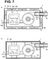
- FIGs. 7(A) and 7(B) are schematic views illustrating the modified examples of the chamber forming member. Note that, the respiratory assistance device 1 according to the first embodiment is taken as an example.
- a first modified example of the chamber forming member is indicated with a reference numeral 67.
- the chamber forming member 67 includes a plurality of base shafts 67a provided outside the housing 15, and plates 67b provided at tip ends of the plurality of base shafts 67a on a one-by-one basis. Each plate 67b supports the bag 16. In each plate 67b, a plurality of air holes 67b1 are formed.
- a second modified example of the chamber forming member is indicated with a reference numeral 77a and 77b.
- This chamber forming member includes a plurality of base shafts 77a provided outside the blower 10 or the control box 11, and a box-shaped frame 77b provided at tip ends of the plurality of base shafts 77a.
- the frame 77b is, for example, in a mesh structure (not shown) and has air for example, in a mesh structure (not shown) and has air permeability.
- the frame 77b supports the bag 16. It is noted that the housing 15 is not provided in this modified example.
- the respiratory assistance device 1 according to the first embodiment may be provided with the chamber forming member 27 of the respiratory assistance device 2 according to the second embodiment. That is to say, both of the chamber forming member 17 constituted by the plurality of projections 17a attached to the outside of the housing 15 and the chamber forming member 27 constituted by the plurality of projections 27a attached to the inside of the bag 16 may be provided.
- the respiratory assistance device 4 according to the second explanatory example may be provided with the chamber forming member 57 of the respiratory assistance device 5 according to the third explanatory example. That is to say, both of the chamber forming member 47 constituted by the plurality of projections 47a attached to the inside of the cover 46 and the chamber forming member 57 constituted by the plurality of projections 57a attached to the outside of the mask 45 may be provided.
Description
- The present invention relates to a filter structure for a blower.
- Sleep apnea is caused by a root of a tongue and a soft palate moving down due to flaccid muscles during sleep and clogging a trachea. Patients with this respiration disorder use respiratory assistance devices, which prevent the clogging by the application of a positive pressure to the trachea (refer to Japanese Patent Application Laid-Open
JP 2013-071004 A WO 2013/133889 A1 . Further respiration devices are known from documentWO 2012/174602 A1 and documentWO 2011/022779 A1 , whereinWO2012/174602 discloses a device according to the preamble of claim 1. - The respiration assistance devices are provided with a blower having a gas suction opening. The blower compresses gas such as air taken from the gas suction opening, and supplies the compressed gas to the trachea of the patient. In the blower, a filter is attached to the gas suction opening in order to prevent the contamination of bacteria, viruses, and dust into inspiratory gas.
- However, since the gas suction opening is not large in size, neither is the filter attached to the gas suction opening, and therefore the filter is easily clogged. The clogged filter degrades the performance of the blower, and interferes with the supply of a sufficient amount of gas to the trachea of the patient, thus failing to prevent the clogging of the trachea. That is to say, the apnea may occur even with a treatment using the respiratory assistance device. In order to avoid such a risk, maintenance including filter replacement is required on a regular basis. Depending on a usage environment, the frequency of the filter maintenance is increased, thus expending much effort.
- The present invention has been made in consideration of the above problem, and an object thereof is to provide a filter structure that reduces effort required for maintenance of a filter.
-
- (1) The present invention is a filter structure characterized by including: a blower having a gas suction opening, the blower compressing gas taken from the gas suction opening and supplying the compressed gas to respiratory organs of a user; a housing that contains the blower and has an air passage opening connected to the gas suction opening; a bag at least part of which is made of a filter material, the bag covering the housing; and a chamber forming member disposed between the housing and the bag, the chamber forming member forming a chamber between the air passage opening and the filter material. The filter structure allows a gas flow from outside the bag into the chamber through said filter material of said bag, and from the chamber into the housing through said air passage opening.
- According to the present invention, it is possible to significantly increase the size of a filter. Thus, even if part of the filter is clogged, a sufficient amount of gas can be supplied to the trachea of a user without degrading the performance of the blower. Thus, the partial clogging of the filter does not require maintenance of the filter. In other words, it is possible to reduce effort for the maintenance of the filter.
- Since the bag made of the filter material covers the entire device, the device is protected from bacteria, viruses, and dirt.
- Patterning or coloring the exterior of the bag serves to improve a bag design. As a result, it is possible to get rid of a negative image as a medical appliance. This brings the user an easy feeling about use. Thus, a product's value rises.
- (2) A preferable embodiment of the present invention is a filter structure
described in the above (1) and characterized in that the bag is formed by closing an opening, and replaceable.
The above-described embodiment allows easy replacement of the filter. As a result, it is possible to further reduce the effort for the maintenance of the filter.
Replacement among a plurality of types of bags having different patterns or colors serves to change the image of a product. As a result, the product's value further rises. - (3) A further preferable embodiment of the present invention is a filter structure described in the above (2) and characterized in that the opening is openable and reclosable.
According to the above-described embodiment, the filter can be detached and cleaned. As a result, it is possible to further reduce the effort for the maintenance of the filter. - (4) A further preferable embodiment of the present invention is a filter structure according
to any one of the above (1) to (3) and characterized in that the filter material is a nonwoven paper. - The embodiment described above results in a reduction in manufacturing costs.
- The exterior of the bag can be easily patterned or colored by printing on the nonwoven paper without a cost increase. That is to say, a bag design is easily improved. Advantageous Effects of Invention
- The filter structure described in the above (1) to (4) of the present invention has the superior effect of reducing effort for maintenance of the filter.
-
-
FIG. 1 is an external view of a respiratory assistance device that adopts a filter structure according to a first embodiment of the present invention. -
FIG. 2 is a schematic view illustrating the inside of the respiratory assistance device illustrated inFIG. 1 . -
FIG. 3 is a schematic view illustrating the inside of a respiratory assistance device that adopts a filter structure according to a second embodiment of the present invention. -
FIG. 4 is a schematic view illustrating the inside of a respiratory assistance device that adopts a filter structure according to a first explanatory example. -
FIG. 5 is a schematic view illustrating the inside of a respiratory assistance device that adopts a filter structure according to a second explanatory example. -
FIG. 6 is a schematic view illustrating the inside of a respiratory assistance device that adopts a filter structure according to a third explanatory example. -
FIGs. 7(A) and 7(B) are schematic views illustrating modified examples of a chamber forming member. - A respiratory assistance device according to the present invention will be hereinafter described in detail with reference to the drawings.
- [First Embodiment] First, the structure of a respiratory assistance device 1 that adopts a filter structure according to an embodiment of the present invention will be described with reference to
FIGs. 1 and 2. FIG. 1 is an external view of the respiratory assistance device 1.FIG. 2 is a schematic view illustrating the inside of the respiratory assistance device 1. Note that, part of the structure is appropriately omitted in each of these and subsequent drawings to simplify the drawings. - The respiratory assistance device 1 illustrated in
FIGs. 1 and 2 is used by a patient (user) of a respiration disorder to generate a positive pressure in his/her trachea. More specifically, the respiratory assistance device 1 includes ablower 10, acontrol box 11, anair feed pipe 12, apower cord 13, aconnection cord 14, ahousing 15, abag 16, achamber forming member 17, O-rings - The
blower 10 is contained in thehousing 15. Theblower 10 is controlled by a control unit (not shown) in thecontrol box 11. That is, theblower 10 is operated under the control of the control unit, and the control unit manages an operation state thereof. Theblower 10 has a gas suction opening 10a, an air feed opening 10b, and the like. Theblower 10 compresses gas such as air taken through thegas suction opening 10a, and supplies the compressed gas to respiratory organs of the patient through theair feed opening 10b and the like. Note that, theblower 10 has a well-known structure and hence the detailed description thereof will be omitted using, for example, Japanese Patent No.5211302 - The
control box 11 is contained in thehousing 15. Thecontrol box 11 is provided with amonitor 11a,buttons 11b, and the like. Thecontrol box 11 contains the control unit (not shown). Themonitor 11a is, for example, a liquid crystal display to display an operation state of the respiratory assistance device 1. Thebuttons 11b function as a man-machine interface by the operation of which predetermined signals are inputted to the control unit. The control unit is operated by power supplied from thepower cord 13. The control unit performs various controls in response to the predetermined signals inputted by the operation of thebuttons 11b. To be more specific, the control unit includes a CPU, a RAM, a ROM, and the like. The CPU is a so-called central processing unit, which executes various programs to implement various functions. The RAM is used as work space for the CPU. The ROM stores a basic OS and the programs executed by the CPU. - The
air feed pipe 12 is provided so as to penetrate thehousing 15 and thebag 16. Theair feed pipe 12 is connected to theair feed opening 10b of theblower 10 at its proximal end, and connected to aduct 20 in a detachable manner at its distal end. Theair feed pipe 12 leads the gas fed from theair feed opening 10b of theblower 10 into theduct 20. - The
power cord 13 extends from thecontrol box 11 so as to penetrate thehousing 15 and thebag 16. Through thepower cord 13, the control unit (not shown) in thecontrol box 11 is powered from outside. - The
connection cord 14 electrically connects between the control unit (not shown) in thecontrol box 11 and a motor (not shown) in theblower 10. Through theconnection cord 14, an electric signal is sent from the control unit to the motor. - The
housing 15 contains theblower 10, thecontrol box 11, theair feed pipe 12, and the like. Thehousing 15 is formed withair passage openings 15a and the like. Theair passage openings 15a are formed for the purpose of taking the air, which is to be taken into theblower 10, from the outside of thehousing 15 to the inside thereof. A plurality ofprojections 17a, which constitute thechamber forming member 17, are attached to the outside of thehousing 15. - The
bag 16 for covering thehousing 15 is made of anonwoven paper 16a having an opened window (with no reference numeral), and atransparent film 16b for closing the window formed in thenonwoven paper 16a. Thenonwoven paper 16a functions as a filter. In thenonwoven paper 16a, a hole 16a1 is formed to pass theair feed pipe 12, and a hole 16a2 is formed to pass thepower cord 13. The O-rings bag 16 is formed by closing an opening (not shown) and replaceable. The opening of thebag 16 is openable and reclosable. At least part of thebag 16 may be formed of thenonwoven paper 16a. Also, the exterior of thebag 16 may be patterned or colored. Thebag 16 does not pass gas except for the portion of thenonwoven paper 16a. - The
chamber forming member 17 is present between thehousing 15 and thebag 16, and forms a chamber CAM between each air passage opening 15a of thehousing 15 and thenonwoven paper 16a constituting thebag 16. Thechamber forming member 17 is constituted by the plurality ofprojections 17a attached to the outside of thehousing 15. - The O-
rings nonwoven paper 16a, respectively. Into the O-ring 18, theair feed pipe 12 is fitted. Into the O-ring 19, thepower cord 13 is fitted. - The
duct 20 leads the gas fed through theair feed pipe 12 to the respiratory organs of the patient. - Next, a gas flow in the respiratory assistance device 1 will be described with reference to
FIG. 2 . - Upon operating the
blower 10, gas outside thebag 16 is taken into the chamber CAM formed inside thebag 16 through thenonwoven paper 16a. The gas taken into the chamber CAM is taken into thehousing 15 through theair passage openings 15a. The gas taken into thehousing 15 is taken into theblower 10 through thegas suction opening 10a. The gas taken into theblower 10 is compressed and supplied to the respiratory organs of the patient through theair feed opening 10b, theair feed pipe 12, theduct 20, and the like. - As described above, the filter structure that the respiratory assistance device 1 adopts allows a significant increase in the area of the filter. Thus, even if part of the
nonwoven paper 16a, used as the filter, is clogged, a sufficient amount of gas can be supplied to the trachea of the patient without degrading the performance of theblower 10. Therefore, even if part of thenonwoven paper 16a is clogged, the nonwoven paper does not require maintenance. In other words, it is possible to reduce effort for the maintenance of thenonwoven paper 16a. - Since the
bag 16 made of thenonwoven paper 16a covers the entire device, the device can be protected from bacteria, viruses, and dirt. - Patterning or coloring the exterior of the
bag 16 serves to improve a bag design. As a result, it is possible to get rid of a negative image as a medical appliance. This brings the patient an easy feeling about use. Thus, a product's value rises. - Furthermore, since the
bag 16 is formed by closing the opening (not shown) and replaceable, thenonwoven paper 16a, which functions as the filter, can be easily replaced. As a result, it is possible to further reduce the effort for the maintenance of thenonwoven paper 16a. - Replacement among a plurality of types of
bags 16 having different patterns or colors serves to change the image of a product. As a result, the product's value further rises. - Since the opening (not shown) of the
bag 16 is openable and reclosable, thenonwoven paper 16a, which functions as the filter, can be detached and cleaned. As a result, it is possible to further reduce the effort for the maintenance of thenonwoven paper 16a. - Moreover, using the
nonwoven paper 16a as the filter allows low manufacturing costs. - The exterior of the
bag 16 is easily patterned or colored without a cost increase by printing on thenonwoven paper 16a. That is to say, a bag design is easily improved. - [Second Embodiment] Next, the structure of a
respiratory assistance device 2 that adopts a filter structure according to an embodiment of the present invention will be described with reference toFIG. 3. FIG. 3 is a schematic view illustrating the inside of therespiratory assistance device 2. Note that, only characteristic portions of the respiratory Note that, only characteristic portions of therespiratory assistance device 2 will be described here, though a description about the same structures, effects, and advantages as the respiratory assistance device 1 will be appropriately omitted. Also in each of embodiments described below, only characteristic portions will be described, though a description about the same structures, effects, and advantages as the other respiratory assistance device will be appropriately omitted. - The
respiratory assistance device 2 illustrated inFIG. 3 is different from the respiratory assistance device 1 according to the first embodiment in terms of providing achamber forming member 27, instead of thechamber forming member 17. - The
chamber forming member 27 is constituted by a plurality ofprojections 27a attached to the inside of thebag 16. - [First explanatory example] Next, the structure of a
respiratory assistance device 3 that adopts a filter structure according to an explanatory example will be described with reference toFIG. 4. FIG. 4 is a schematic view illustrating the inside of therespiratory assistance device 3. - is provided with a
blower 10, a control box (not shown), amask 36, prongs 37, and the like. - The
blower 10 is attached to the inside of themask 36. That is, theblower 10 is disposed in a chamber CAM formed between themask 36 and a face of a patient. A gas suction opening 10a of theblower 10 takes in gas present in the chamber CAM. - The control box (not shown) is provided outside the
mask 36 in an independent manner. A control unit in the control box is electrically connected to a motor (not shown) of theblower 10 through a connection cord (not shown). - The
mask 36 is fixed on the face of the patient using a fixture such as a band (not shown). Themask 36 covers a mouth or nose of the patient so as to form the chamber CAM between the face of the patient and themask 36. Themask 36 is made of a filter such as a nonwoven paper. It is noted that at least part of themask 36 may be formed of the filter. Themask 36 may be appropriately provided with a frame or the like for reinforcement. Themask 36 does not pass gas except for the portion of the filter. - An
air feed opening 10b of theblower 10 is connected to proximal ends of theprongs 37, and distal ends of the prongs proximal ends of theprongs 37, and distal ends of theprongs 37 are inserted into the nose of the patient. Theprongs 37 lead the gas fed from theair feed opening 10b of theblower 10 to the nose of the patient. - Note that, the
respiratory assistance device 3 may be provided with a chamber forming member that is disposed between theblower 10 and themask 36 to maintain the chamber CAM between the gas suction opening 10a of theblower 10 and a filter portion of themask 36. The chamber forming member may be provided outside theblower 10 or inside themask 36. - Next, a gas flow in the
respiratory assistance device 3 will be described with reference toFIG. 4 . - Upon operating the
blower 10, gas outside themask 36 is taken into the chamber CAM formed inside themask 36 through themask 36. The gas taken into the chamber CAM is taken into theblower 10 through thegas suction opening 10a. The gas taken into theblower 10 is compressed and supplied to the respiratory organs of the patient through theair feed opening 10b, theprongs 37, and the like. - [Second explanatory example] Next, the structure of a respiratory assistance device 4 that adopts a filter structure according to an explanatory example will be described illustrating the inside of the respiratory assistance device 4.
- The respiratory assistance device 4 illustrated in
FIG. 5 is provided with ablower 10, a control box (not shown), amask 45, a cover 46, achamber forming member 47, and the like. - The
blower 10 is provided in themask 45. Agas suction opening 10a is disposed so as to face the outside of themask 45. Thisgas suction opening 10a takes in gas from the outside of themask 45. Anair feed opening 10b is disposed so as to face the inside of themask 45. This air feed opening 10b feeds the gas to the inside of themask 45. Theblower 10 compresses the gas taken by thegas suction opening 10a, and supplies the compressed gas to the respiratory organs of the patient through the inside of themask 45. - The
mask 45 covers a mouth or nose of the patient so as to form a chamber CAM1 between a face of the patient and themask 45. - The cover 46 covers the
mask 45. At least part of the cover 46 is formed of a filter (having no reference numeral) such as a nonwoven paper. Note that, the cover 46 does not pass gas except for the portion of the filter. - The
chamber forming member 47 is disposed between themask 45 and the cover 4 so as to form a chamber CAM2 between the gas suction opening 10a of theblower 10 and the filter (having no reference numeral) constituting the cover 46. Thechamber forming member 47 is constituted by a plurality ofprojections 47a attached to the inside of the cover 46. - Next, a gas flow in the respiratory assistance device 4 will be described with reference to
FIG. 5 . - Upon operating the
blower 10, gas outside the cover 46 is taken into the chamber CAM2 formed inside the cover 46 through the cover 46. The gas taken into the chamber CAM2 is taken into theblower 10 through thegas suction opening 10a. The gas taken into theblower 10 is compressed and supplied to the respiratory organs of the patient through theair feed opening 10b, the chamber CAM1, and the like. - [Third explanatory example] Next, the structure of a
respiratory assistance device 5 that adopts a filter structure according to an explanatory example will be described with reference toFIG. 6. FIG. 6 is a schematic view illustrating the inside of therespiratory assistance device 5. - The
respiratory assistance device 5 illustrated inFIG. 6 is different from the respiratory assistance device 4chamber forming member 57, instead of thechamber forming member 47. - The
chamber forming member 47 is constituted by a plurality ofprojections 47a attached to the outside of themask 45. - The present invention is not limited to each of the embodiments described above, but can be variously modified within a range without departing from the general meaning and technical thought thereof.
- That is to say, in each of the embodiments described above, the position, size (dimensions), shape, material, orientation, and number of each component are changeable in an appropriate manner.
- For example, in the above-described first and second embodiments, the
bag 16 is not limited to be formed of thenonwoven paper 16a, as long as it is formed of a filter material. For example, thebag 16 may be formed of a nonwoven cloth. - Also, in each of the embodiments described above, the plurality of
projections chamber forming members chamber forming members projections - Next, modified examples of the chamber forming member will be described with reference to
FIGs. 7(A) and 7(B). FIGs. 7(A) and 7(B) are schematic views illustrating the modified examples of the chamber forming member. Note that, the respiratory assistance device 1 according to the first embodiment is taken as an example. - As illustrated in
FIG. 7(A) , a first modified example of the chamber forming member is indicated with areference numeral 67. Thechamber forming member 67 includes a plurality ofbase shafts 67a provided outside thehousing 15, andplates 67b provided at tip ends of the plurality ofbase shafts 67a on a one-by-one basis. Eachplate 67b supports thebag 16. In eachplate 67b, a plurality of air holes 67b1 are formed. - As illustrated in
FIG. 7(B) , a second modified example of the chamber forming member is indicated with areference numeral base shafts 77a provided outside theblower 10 or thecontrol box 11, and a box-shapedframe 77b provided at tip ends of the plurality ofbase shafts 77a. Theframe 77b is, for example, in a mesh structure (not shown) and has air for example, in a mesh structure (not shown) and has air permeability. Theframe 77b supports thebag 16. It is noted that thehousing 15 is not provided in this modified example. - Alternatively, the components of each of the above-described embodiments may be applied to the other embodiments if applicable.
- For example, the respiratory assistance device 1 according to the first embodiment may be provided with the
chamber forming member 27 of therespiratory assistance device 2 according to the second embodiment. That is to say, both of thechamber forming member 17 constituted by the plurality ofprojections 17a attached to the outside of thehousing 15 and thechamber forming member 27 constituted by the plurality ofprojections 27a attached to the inside of thebag 16 may be provided. - Or, the respiratory assistance device 4 according to the second explanatory example may be provided with the
chamber forming member 57 of therespiratory assistance device 5 according to the third explanatory example. That is to say, both of thechamber forming member 47 constituted by the plurality ofprojections 47a attached to the inside of the cover 46 and thechamber forming member 57 constituted by the plurality ofprojections 57a attached to the outside of themask 45 may be provided.
Claims (4)
- A filter structure comprising:a blower (10) having a gas suction opening (10a), the blower (10) being configured for compressing gas taken from the gas suction opening (10a) and supplying the compressed gas to respiratory organs of a user;a housing (15) that contains the blower (10) and has an air passage opening (15a) connected to the gas suction opening (10a);a bag (16) at least part of which is made of a filter material (16a), the bag (16) covering the housing (15); characterized in that a chamber forming member (17; 27) is disposed between the housing (15) and the bag (16), the chamber forming member (17; 27) forming a chamber (CAM) between the air passage opening (15a) and the filter material (16a), wherein the filter structure allows a gas flow from outside the bag (16) into the chamber (CAM) through said filter material (16a) of said bag (16), and from the chamber (CAM) into the housing (15) through said air passage opening (15a).
- The filter structure according to claim 1, wherein the bag (16) is formed by closing an opening, and replaceable.
- The filter structure according to claim 2, wherein the opening is openable and recloseable.
- The filter structure according to any one of claims 1 to 3, wherein the filter material (16a) is a nonwoven paper.
Applications Claiming Priority (2)
| Application Number | Priority Date | Filing Date | Title |
|---|---|---|---|
| JP2013268195A JP6455653B2 (en) | 2013-12-26 | 2013-12-26 | Filter structure |
| PCT/JP2014/084243 WO2015099011A1 (en) | 2013-12-26 | 2014-12-25 | Filter structure |
Publications (3)
| Publication Number | Publication Date |
|---|---|
| EP3078392A1 EP3078392A1 (en) | 2016-10-12 |
| EP3078392A4 EP3078392A4 (en) | 2017-04-05 |
| EP3078392B1 true EP3078392B1 (en) | 2018-12-05 |
Family
ID=53478858
Family Applications (1)
| Application Number | Title | Priority Date | Filing Date |
|---|---|---|---|
| EP14873133.4A Active EP3078392B1 (en) | 2013-12-26 | 2014-12-25 | Filter structure |
Country Status (5)
| Country | Link |
|---|---|
| US (1) | US10974011B2 (en) |
| EP (1) | EP3078392B1 (en) |
| JP (1) | JP6455653B2 (en) |
| CN (1) | CN105848701B (en) |
| WO (1) | WO2015099011A1 (en) |
Families Citing this family (4)
| Publication number | Priority date | Publication date | Assignee | Title |
|---|---|---|---|---|
| CN115252995A (en) * | 2015-10-23 | 2022-11-01 | 费雪派克医疗保健有限公司 | Apparatus for providing a flow of air to a user |
| WO2022125603A1 (en) * | 2020-12-08 | 2022-06-16 | Corvent Medical, Inc. | Automated ventilator |
| US11318333B1 (en) * | 2021-04-17 | 2022-05-03 | Christopher T. Ellerbrake | Respiratory protection system |
| US20230076766A1 (en) * | 2021-08-20 | 2023-03-09 | Sol-Gel Technologies Ltd. | Method for treatment of rosacea in patients aged 35-64 years |
Family Cites Families (40)
| Publication number | Priority date | Publication date | Assignee | Title |
|---|---|---|---|---|
| US4197841A (en) * | 1978-05-22 | 1980-04-15 | Auergesellschaft Gmbh | Respirator with protective cover |
| GB8809221D0 (en) * | 1988-04-19 | 1988-05-25 | Safety Products Ltd | Improvements in/relating to safety visors |
| US5104430A (en) * | 1991-06-11 | 1992-04-14 | Her Mou Lin | Mask with an air filtering device |
| US5372130A (en) * | 1992-02-26 | 1994-12-13 | Djs&T Limited Partnership | Face mask assembly and method having a fan and replaceable filter |
| US5592936A (en) * | 1995-08-28 | 1997-01-14 | Stackhouse, Inc. | Surgical helmet |
| US6014971A (en) * | 1997-08-15 | 2000-01-18 | 3M Innovative Properties Company | Protective system for face and respiratory protection |
| US8701664B2 (en) * | 1998-11-06 | 2014-04-22 | Caradyne (R&D) Limited | Apparatus and method for relieving dyspnoea |
| US6257235B1 (en) * | 1999-05-28 | 2001-07-10 | Kimberly-Clark Worldwide, Inc. | Face mask with fan attachment |
| US8517012B2 (en) * | 2001-12-10 | 2013-08-27 | Resmed Limited | Multiple stage blowers and volutes therefor |
| US6854764B2 (en) * | 2002-02-20 | 2005-02-15 | Autoliv Asp, Inc. | Flexible airbag inflator |
| US6823867B2 (en) * | 2002-04-12 | 2004-11-30 | 3M Innovative Properties Company | Pouch for the blower unit of a powered air purifying respirator |
| CN2607152Y (en) | 2003-05-02 | 2004-03-24 | 王建刚 | Protective helmet for medical personnel |
| CN1202877C (en) | 2003-08-15 | 2005-05-25 | 北京泰达新兴医学工程技术有限公司 | Respirator capable of being sterilized by soaking |
| JP2007506482A (en) * | 2003-09-25 | 2007-03-22 | レスメド リミテッド | Respiratory mask and system |
| US20060096596A1 (en) * | 2004-11-05 | 2006-05-11 | Occhialini James M | Wearable system for positive airway pressure therapy |
| US20070101867A1 (en) | 2005-11-08 | 2007-05-10 | Hunter Charles E | Air sterilization apparatus |
| US20070102280A1 (en) | 2005-11-08 | 2007-05-10 | Hunter C E | Air supply apparatus |
| US20070163588A1 (en) * | 2005-11-08 | 2007-07-19 | Jack Hebrank | Respirators for Delivering Clean Air to an Individual User |
| DE202006003137U1 (en) * | 2006-02-24 | 2007-07-12 | Mann+Hummel Gmbh | Filter pipe |
| JP4612606B2 (en) * | 2006-10-04 | 2011-01-12 | 興研株式会社 | Mask device with blower |
| DE102006047316A1 (en) | 2006-10-06 | 2008-04-10 | Pfannenberg Gmbh | filter Fans |
| CN200974415Y (en) * | 2006-11-30 | 2007-11-14 | 赵连柱 | Electric dust-absorbing type blackboard eraser |
| US20080216831A1 (en) * | 2007-03-08 | 2008-09-11 | Mcginnis William J | Standalone cpap device and method of using |
| US9132252B2 (en) | 2009-05-29 | 2015-09-15 | Resmed Limited | PAP system |
| US9248248B2 (en) * | 2009-07-17 | 2016-02-02 | Paftec Technologies Pty Ltd | Respirator |
| WO2011017763A1 (en) * | 2009-08-11 | 2011-02-17 | Resmed Motor Technologies Inc. | Single stage, axial symmetric blower and portable ventilator |
| SG169911A1 (en) * | 2009-09-25 | 2011-04-29 | Jcs Group | Respiratory device with filter |
| JP2013508087A (en) * | 2009-10-20 | 2013-03-07 | デシャム・メディカル,エルエルシー | Integrated positive airway pressure device |
| JP2011120853A (en) * | 2009-12-09 | 2011-06-23 | Shunsuke Kametani | Simple cylindrical air filter |
| US9295801B2 (en) * | 2010-05-25 | 2016-03-29 | Fisher & Paykel Healthcare Limited | Breathing tube |
| EP3323458B1 (en) * | 2011-06-21 | 2022-08-31 | ResMed Pty Ltd | Pap system |
| KR101165763B1 (en) * | 2011-09-08 | 2012-07-20 | 정정대 | Dust-proof mask |
| US9649459B2 (en) | 2011-09-26 | 2017-05-16 | Resmed Paris Sas | Ventilator apparatus and method |
| EP2822626B1 (en) | 2012-03-06 | 2017-09-27 | ResMed Motor Technologies Inc. | Flow generator |
| US9498656B2 (en) * | 2012-07-11 | 2016-11-22 | B/E Aerospace, Inc. | Aircraft crew member protective breathing apparatus |
| JP5211302B1 (en) | 2012-09-03 | 2013-06-12 | 株式会社メトラン | Blower |
| CN202844407U (en) * | 2012-10-30 | 2013-04-03 | 李明忠 | Independent double-cover subchannel breathing filter |
| JP5358773B1 (en) * | 2013-02-21 | 2013-12-04 | 株式会社メトラン | Respiratory device |
| US20140261425A1 (en) * | 2013-03-13 | 2014-09-18 | Robert A. Connor | Wearable Positive Airway Pressure (PAP) with Primary and Bolus Airflow |
| DE102013006915B4 (en) * | 2013-04-20 | 2018-07-19 | Dräger Safety AG & Co. KGaA | PAPR |
-
2013
- 2013-12-26 JP JP2013268195A patent/JP6455653B2/en active Active
-
2014
- 2014-12-25 EP EP14873133.4A patent/EP3078392B1/en active Active
- 2014-12-25 US US15/107,016 patent/US10974011B2/en active Active
- 2014-12-25 WO PCT/JP2014/084243 patent/WO2015099011A1/en active Application Filing
- 2014-12-25 CN CN201480071184.9A patent/CN105848701B/en active Active
Non-Patent Citations (1)
| Title |
|---|
| None * |
Also Published As
| Publication number | Publication date |
|---|---|
| CN105848701A (en) | 2016-08-10 |
| JP6455653B2 (en) | 2019-01-23 |
| CN105848701B (en) | 2020-09-01 |
| US20170028157A1 (en) | 2017-02-02 |
| JP2015123154A (en) | 2015-07-06 |
| EP3078392A1 (en) | 2016-10-12 |
| WO2015099011A1 (en) | 2015-07-02 |
| US10974011B2 (en) | 2021-04-13 |
| EP3078392A4 (en) | 2017-04-05 |
Similar Documents
| Publication | Publication Date | Title |
|---|---|---|
| EP3078392B1 (en) | Filter structure | |
| CN108310577A (en) | A kind of anti-infection mask of breathing endoscope diagnosis and treatment | |
| EP3865167A1 (en) | Textile patient interface | |
| CN208756733U (en) | A kind of anti-infection mask of breathing endoscope diagnosis and treatment | |
| CN107548314A (en) | Prevent from sucking the mouth mask of pollutant | |
| US20100024824A1 (en) | Passive gas regulating valve for a respiratory system | |
| JP2012505692A5 (en) | ||
| CN104548406A (en) | Mask power adapting device | |
| DE112010001198T5 (en) | Inhalers and functional units attachable to the inhaler | |
| KR101505648B1 (en) | Nose mask | |
| CN105126219A (en) | Micro breathing machine | |
| KR20160127637A (en) | Mask having an hot-air supplying funcion | |
| CN207980145U (en) | A kind of totally-enclosed respirator of division of respiratory disease | |
| CN103736182A (en) | Breathing machine | |
| WO2018098657A1 (en) | Intelligent mask and method for adjusting inspiration supply amount of same | |
| CN212089611U (en) | Throat swab safety mask for fulminating airway infectious diseases | |
| CN206534965U (en) | A kind of lung ventilator | |
| WO2014164813A1 (en) | Ventilation mask with integrated piloted exhalation valve | |
| CN207167847U (en) | A kind of spray mask that can change filtration core | |
| CN108030987A (en) | A kind of convenient mask worn | |
| CN213549883U (en) | Nose plug type mask | |
| CN108543186A (en) | A kind of anaesthetic mask | |
| CN214103319U (en) | Reusable mask with replaceable inner core | |
| CN111543701A (en) | Reusable mask with replaceable inner core | |
| CN214965337U (en) | Mask for respiratory endoscopy |
Legal Events
| Date | Code | Title | Description |
|---|---|---|---|
| PUAI | Public reference made under article 153(3) epc to a published international application that has entered the european phase |
Free format text: ORIGINAL CODE: 0009012 |
|
| 17P | Request for examination filed |
Effective date: 20160707 |
|
| AK | Designated contracting states |
Kind code of ref document: A1 Designated state(s): AL AT BE BG CH CY CZ DE DK EE ES FI FR GB GR HR HU IE IS IT LI LT LU LV MC MK MT NL NO PL PT RO RS SE SI SK SM TR |
|
| AX | Request for extension of the european patent |
Extension state: BA ME |
|
| RIC1 | Information provided on ipc code assigned before grant |
Ipc: A61M 16/00 20060101AFI20161116BHEP Ipc: A61M 16/06 20060101ALI20161116BHEP |
|
| A4 | Supplementary search report drawn up and despatched |
Effective date: 20170306 |
|
| DAX | Request for extension of the european patent (deleted) | ||
| RIC1 | Information provided on ipc code assigned before grant |
Ipc: A61M 16/06 20060101ALI20170228BHEP Ipc: A61M 16/00 20060101AFI20170228BHEP |
|
| STAA | Information on the status of an ep patent application or granted ep patent |
Free format text: STATUS: EXAMINATION IS IN PROGRESS |
|
| 17Q | First examination report despatched |
Effective date: 20170407 |
|
| GRAP | Despatch of communication of intention to grant a patent |
Free format text: ORIGINAL CODE: EPIDOSNIGR1 |
|
| STAA | Information on the status of an ep patent application or granted ep patent |
Free format text: STATUS: GRANT OF PATENT IS INTENDED |
|
| INTG | Intention to grant announced |
Effective date: 20180622 |
|
| GRAS | Grant fee paid |
Free format text: ORIGINAL CODE: EPIDOSNIGR3 |
|
| GRAA | (expected) grant |
Free format text: ORIGINAL CODE: 0009210 |
|
| GRAA | (expected) grant |
Free format text: ORIGINAL CODE: 0009210 |
|
| STAA | Information on the status of an ep patent application or granted ep patent |
Free format text: STATUS: THE PATENT HAS BEEN GRANTED |
|
| AK | Designated contracting states |
Kind code of ref document: B1 Designated state(s): AL AT BE BG CH CY CZ DE DK EE ES FI FR GB GR HR HU IE IS IT LI LT LU LV MC MK MT NL NO PL PT RO RS SE SI SK SM TR |
|
| REG | Reference to a national code |
Ref country code: GB Ref legal event code: FG4D |
|
| REG | Reference to a national code |
Ref country code: CH Ref legal event code: EP |
|
| REG | Reference to a national code |
Ref country code: AT Ref legal event code: REF Ref document number: 1072287 Country of ref document: AT Kind code of ref document: T Effective date: 20181215 |
|
| REG | Reference to a national code |
Ref country code: IE Ref legal event code: FG4D |
|
| REG | Reference to a national code |
Ref country code: DE Ref legal event code: R096 Ref document number: 602014037643 Country of ref document: DE |
|
| REG | Reference to a national code |
Ref country code: NL Ref legal event code: MP Effective date: 20181205 |
|
| REG | Reference to a national code |
Ref country code: AT Ref legal event code: MK05 Ref document number: 1072287 Country of ref document: AT Kind code of ref document: T Effective date: 20181205 |
|
| REG | Reference to a national code |
Ref country code: LT Ref legal event code: MG4D |
|
| PG25 | Lapsed in a contracting state [announced via postgrant information from national office to epo] |
Ref country code: HR Free format text: LAPSE BECAUSE OF FAILURE TO SUBMIT A TRANSLATION OF THE DESCRIPTION OR TO PAY THE FEE WITHIN THE PRESCRIBED TIME-LIMIT Effective date: 20181205 Ref country code: AT Free format text: LAPSE BECAUSE OF FAILURE TO SUBMIT A TRANSLATION OF THE DESCRIPTION OR TO PAY THE FEE WITHIN THE PRESCRIBED TIME-LIMIT Effective date: 20181205 Ref country code: LT Free format text: LAPSE BECAUSE OF FAILURE TO SUBMIT A TRANSLATION OF THE DESCRIPTION OR TO PAY THE FEE WITHIN THE PRESCRIBED TIME-LIMIT Effective date: 20181205 Ref country code: LV Free format text: LAPSE BECAUSE OF FAILURE TO SUBMIT A TRANSLATION OF THE DESCRIPTION OR TO PAY THE FEE WITHIN THE PRESCRIBED TIME-LIMIT Effective date: 20181205 Ref country code: NO Free format text: LAPSE BECAUSE OF FAILURE TO SUBMIT A TRANSLATION OF THE DESCRIPTION OR TO PAY THE FEE WITHIN THE PRESCRIBED TIME-LIMIT Effective date: 20190305 Ref country code: ES Free format text: LAPSE BECAUSE OF FAILURE TO SUBMIT A TRANSLATION OF THE DESCRIPTION OR TO PAY THE FEE WITHIN THE PRESCRIBED TIME-LIMIT Effective date: 20181205 Ref country code: BG Free format text: LAPSE BECAUSE OF FAILURE TO SUBMIT A TRANSLATION OF THE DESCRIPTION OR TO PAY THE FEE WITHIN THE PRESCRIBED TIME-LIMIT Effective date: 20190305 Ref country code: FI Free format text: LAPSE BECAUSE OF FAILURE TO SUBMIT A TRANSLATION OF THE DESCRIPTION OR TO PAY THE FEE WITHIN THE PRESCRIBED TIME-LIMIT Effective date: 20181205 |
|
| PG25 | Lapsed in a contracting state [announced via postgrant information from national office to epo] |
Ref country code: GR Free format text: LAPSE BECAUSE OF FAILURE TO SUBMIT A TRANSLATION OF THE DESCRIPTION OR TO PAY THE FEE WITHIN THE PRESCRIBED TIME-LIMIT Effective date: 20190306 Ref country code: RS Free format text: LAPSE BECAUSE OF FAILURE TO SUBMIT A TRANSLATION OF THE DESCRIPTION OR TO PAY THE FEE WITHIN THE PRESCRIBED TIME-LIMIT Effective date: 20181205 Ref country code: AL Free format text: LAPSE BECAUSE OF FAILURE TO SUBMIT A TRANSLATION OF THE DESCRIPTION OR TO PAY THE FEE WITHIN THE PRESCRIBED TIME-LIMIT Effective date: 20181205 Ref country code: SE Free format text: LAPSE BECAUSE OF FAILURE TO SUBMIT A TRANSLATION OF THE DESCRIPTION OR TO PAY THE FEE WITHIN THE PRESCRIBED TIME-LIMIT Effective date: 20181205 |
|
| PG25 | Lapsed in a contracting state [announced via postgrant information from national office to epo] |
Ref country code: NL Free format text: LAPSE BECAUSE OF FAILURE TO SUBMIT A TRANSLATION OF THE DESCRIPTION OR TO PAY THE FEE WITHIN THE PRESCRIBED TIME-LIMIT Effective date: 20181205 |
|
| PG25 | Lapsed in a contracting state [announced via postgrant information from national office to epo] |
Ref country code: PL Free format text: LAPSE BECAUSE OF FAILURE TO SUBMIT A TRANSLATION OF THE DESCRIPTION OR TO PAY THE FEE WITHIN THE PRESCRIBED TIME-LIMIT Effective date: 20181205 Ref country code: IT Free format text: LAPSE BECAUSE OF FAILURE TO SUBMIT A TRANSLATION OF THE DESCRIPTION OR TO PAY THE FEE WITHIN THE PRESCRIBED TIME-LIMIT Effective date: 20181205 Ref country code: CZ Free format text: LAPSE BECAUSE OF FAILURE TO SUBMIT A TRANSLATION OF THE DESCRIPTION OR TO PAY THE FEE WITHIN THE PRESCRIBED TIME-LIMIT Effective date: 20181205 Ref country code: PT Free format text: LAPSE BECAUSE OF FAILURE TO SUBMIT A TRANSLATION OF THE DESCRIPTION OR TO PAY THE FEE WITHIN THE PRESCRIBED TIME-LIMIT Effective date: 20190405 |
|
| REG | Reference to a national code |
Ref country code: CH Ref legal event code: PL |
|
| PG25 | Lapsed in a contracting state [announced via postgrant information from national office to epo] |
Ref country code: SK Free format text: LAPSE BECAUSE OF FAILURE TO SUBMIT A TRANSLATION OF THE DESCRIPTION OR TO PAY THE FEE WITHIN THE PRESCRIBED TIME-LIMIT Effective date: 20181205 Ref country code: IS Free format text: LAPSE BECAUSE OF FAILURE TO SUBMIT A TRANSLATION OF THE DESCRIPTION OR TO PAY THE FEE WITHIN THE PRESCRIBED TIME-LIMIT Effective date: 20190405 Ref country code: RO Free format text: LAPSE BECAUSE OF FAILURE TO SUBMIT A TRANSLATION OF THE DESCRIPTION OR TO PAY THE FEE WITHIN THE PRESCRIBED TIME-LIMIT Effective date: 20181205 Ref country code: LU Free format text: LAPSE BECAUSE OF NON-PAYMENT OF DUE FEES Effective date: 20181225 Ref country code: EE Free format text: LAPSE BECAUSE OF FAILURE TO SUBMIT A TRANSLATION OF THE DESCRIPTION OR TO PAY THE FEE WITHIN THE PRESCRIBED TIME-LIMIT Effective date: 20181205 Ref country code: SM Free format text: LAPSE BECAUSE OF FAILURE TO SUBMIT A TRANSLATION OF THE DESCRIPTION OR TO PAY THE FEE WITHIN THE PRESCRIBED TIME-LIMIT Effective date: 20181205 |
|
| REG | Reference to a national code |
Ref country code: DE Ref legal event code: R097 Ref document number: 602014037643 Country of ref document: DE |
|
| REG | Reference to a national code |
Ref country code: IE Ref legal event code: MM4A |
|
| REG | Reference to a national code |
Ref country code: BE Ref legal event code: MM Effective date: 20181231 |
|
| PLBE | No opposition filed within time limit |
Free format text: ORIGINAL CODE: 0009261 |
|
| STAA | Information on the status of an ep patent application or granted ep patent |
Free format text: STATUS: NO OPPOSITION FILED WITHIN TIME LIMIT |
|
| PG25 | Lapsed in a contracting state [announced via postgrant information from national office to epo] |
Ref country code: MC Free format text: LAPSE BECAUSE OF FAILURE TO SUBMIT A TRANSLATION OF THE DESCRIPTION OR TO PAY THE FEE WITHIN THE PRESCRIBED TIME-LIMIT Effective date: 20181205 Ref country code: SI Free format text: LAPSE BECAUSE OF FAILURE TO SUBMIT A TRANSLATION OF THE DESCRIPTION OR TO PAY THE FEE WITHIN THE PRESCRIBED TIME-LIMIT Effective date: 20181205 Ref country code: IE Free format text: LAPSE BECAUSE OF NON-PAYMENT OF DUE FEES Effective date: 20181225 Ref country code: DK Free format text: LAPSE BECAUSE OF FAILURE TO SUBMIT A TRANSLATION OF THE DESCRIPTION OR TO PAY THE FEE WITHIN THE PRESCRIBED TIME-LIMIT Effective date: 20181205 |
|
| 26N | No opposition filed |
Effective date: 20190906 |
|
| PG25 | Lapsed in a contracting state [announced via postgrant information from national office to epo] |
Ref country code: BE Free format text: LAPSE BECAUSE OF NON-PAYMENT OF DUE FEES Effective date: 20181231 |
|
| PG25 | Lapsed in a contracting state [announced via postgrant information from national office to epo] |
Ref country code: LI Free format text: LAPSE BECAUSE OF NON-PAYMENT OF DUE FEES Effective date: 20181231 Ref country code: CH Free format text: LAPSE BECAUSE OF NON-PAYMENT OF DUE FEES Effective date: 20181231 |
|
| PG25 | Lapsed in a contracting state [announced via postgrant information from national office to epo] |
Ref country code: MT Free format text: LAPSE BECAUSE OF NON-PAYMENT OF DUE FEES Effective date: 20181225 |
|
| PG25 | Lapsed in a contracting state [announced via postgrant information from national office to epo] |
Ref country code: TR Free format text: LAPSE BECAUSE OF FAILURE TO SUBMIT A TRANSLATION OF THE DESCRIPTION OR TO PAY THE FEE WITHIN THE PRESCRIBED TIME-LIMIT Effective date: 20181205 |
|
| PG25 | Lapsed in a contracting state [announced via postgrant information from national office to epo] |
Ref country code: CY Free format text: LAPSE BECAUSE OF FAILURE TO SUBMIT A TRANSLATION OF THE DESCRIPTION OR TO PAY THE FEE WITHIN THE PRESCRIBED TIME-LIMIT Effective date: 20181205 Ref country code: MK Free format text: LAPSE BECAUSE OF NON-PAYMENT OF DUE FEES Effective date: 20181205 Ref country code: HU Free format text: LAPSE BECAUSE OF FAILURE TO SUBMIT A TRANSLATION OF THE DESCRIPTION OR TO PAY THE FEE WITHIN THE PRESCRIBED TIME-LIMIT; INVALID AB INITIO Effective date: 20141225 |
|
| PGFP | Annual fee paid to national office [announced via postgrant information from national office to epo] |
Ref country code: DE Payment date: 20221227 Year of fee payment: 9 |
|
| PGFP | Annual fee paid to national office [announced via postgrant information from national office to epo] |
Ref country code: GB Payment date: 20231220 Year of fee payment: 10 |
|
| PGFP | Annual fee paid to national office [announced via postgrant information from national office to epo] |
Ref country code: FR Payment date: 20231219 Year of fee payment: 10 |
|
| PGFP | Annual fee paid to national office [announced via postgrant information from national office to epo] |
Ref country code: DE Payment date: 20231228 Year of fee payment: 10 |