EP3077245B1 - Aufladungsverwaltungssystem für elektrisches oder hybridfahrzeug - Google Patents
Aufladungsverwaltungssystem für elektrisches oder hybridfahrzeug Download PDFInfo
- Publication number
- EP3077245B1 EP3077245B1 EP14828302.1A EP14828302A EP3077245B1 EP 3077245 B1 EP3077245 B1 EP 3077245B1 EP 14828302 A EP14828302 A EP 14828302A EP 3077245 B1 EP3077245 B1 EP 3077245B1
- Authority
- EP
- European Patent Office
- Prior art keywords
- recharge
- value
- current
- cable
- maximum
- Prior art date
- Legal status (The legal status is an assumption and is not a legal conclusion. Google has not performed a legal analysis and makes no representation as to the accuracy of the status listed.)
- Active
Links
Images

Classifications
-
- B—PERFORMING OPERATIONS; TRANSPORTING
- B60—VEHICLES IN GENERAL
- B60L—PROPULSION OF ELECTRICALLY-PROPELLED VEHICLES; SUPPLYING ELECTRIC POWER FOR AUXILIARY EQUIPMENT OF ELECTRICALLY-PROPELLED VEHICLES; ELECTRODYNAMIC BRAKE SYSTEMS FOR VEHICLES IN GENERAL; MAGNETIC SUSPENSION OR LEVITATION FOR VEHICLES; MONITORING OPERATING VARIABLES OF ELECTRICALLY-PROPELLED VEHICLES; ELECTRIC SAFETY DEVICES FOR ELECTRICALLY-PROPELLED VEHICLES
- B60L3/00—Electric devices on electrically-propelled vehicles for safety purposes; Monitoring operating variables, e.g. speed, deceleration or energy consumption
- B60L3/0023—Detecting, eliminating, remedying or compensating for drive train abnormalities, e.g. failures within the drive train
- B60L3/0069—Detecting, eliminating, remedying or compensating for drive train abnormalities, e.g. failures within the drive train relating to the isolation, e.g. ground fault or leak current
-
- B—PERFORMING OPERATIONS; TRANSPORTING
- B60—VEHICLES IN GENERAL
- B60L—PROPULSION OF ELECTRICALLY-PROPELLED VEHICLES; SUPPLYING ELECTRIC POWER FOR AUXILIARY EQUIPMENT OF ELECTRICALLY-PROPELLED VEHICLES; ELECTRODYNAMIC BRAKE SYSTEMS FOR VEHICLES IN GENERAL; MAGNETIC SUSPENSION OR LEVITATION FOR VEHICLES; MONITORING OPERATING VARIABLES OF ELECTRICALLY-PROPELLED VEHICLES; ELECTRIC SAFETY DEVICES FOR ELECTRICALLY-PROPELLED VEHICLES
- B60L3/00—Electric devices on electrically-propelled vehicles for safety purposes; Monitoring operating variables, e.g. speed, deceleration or energy consumption
- B60L3/12—Recording operating variables ; Monitoring of operating variables
-
- B—PERFORMING OPERATIONS; TRANSPORTING
- B60—VEHICLES IN GENERAL
- B60L—PROPULSION OF ELECTRICALLY-PROPELLED VEHICLES; SUPPLYING ELECTRIC POWER FOR AUXILIARY EQUIPMENT OF ELECTRICALLY-PROPELLED VEHICLES; ELECTRODYNAMIC BRAKE SYSTEMS FOR VEHICLES IN GENERAL; MAGNETIC SUSPENSION OR LEVITATION FOR VEHICLES; MONITORING OPERATING VARIABLES OF ELECTRICALLY-PROPELLED VEHICLES; ELECTRIC SAFETY DEVICES FOR ELECTRICALLY-PROPELLED VEHICLES
- B60L53/00—Methods of charging batteries, specially adapted for electric vehicles; Charging stations or on-board charging equipment therefor; Exchange of energy storage elements in electric vehicles
- B60L53/10—Methods of charging batteries, specially adapted for electric vehicles; Charging stations or on-board charging equipment therefor; Exchange of energy storage elements in electric vehicles characterised by the energy transfer between the charging station and the vehicle
- B60L53/14—Conductive energy transfer
- B60L53/16—Connectors, e.g. plugs or sockets, specially adapted for charging electric vehicles
-
- B—PERFORMING OPERATIONS; TRANSPORTING
- B60—VEHICLES IN GENERAL
- B60L—PROPULSION OF ELECTRICALLY-PROPELLED VEHICLES; SUPPLYING ELECTRIC POWER FOR AUXILIARY EQUIPMENT OF ELECTRICALLY-PROPELLED VEHICLES; ELECTRODYNAMIC BRAKE SYSTEMS FOR VEHICLES IN GENERAL; MAGNETIC SUSPENSION OR LEVITATION FOR VEHICLES; MONITORING OPERATING VARIABLES OF ELECTRICALLY-PROPELLED VEHICLES; ELECTRIC SAFETY DEVICES FOR ELECTRICALLY-PROPELLED VEHICLES
- B60L53/00—Methods of charging batteries, specially adapted for electric vehicles; Charging stations or on-board charging equipment therefor; Exchange of energy storage elements in electric vehicles
- B60L53/10—Methods of charging batteries, specially adapted for electric vehicles; Charging stations or on-board charging equipment therefor; Exchange of energy storage elements in electric vehicles characterised by the energy transfer between the charging station and the vehicle
- B60L53/14—Conductive energy transfer
- B60L53/18—Cables specially adapted for charging electric vehicles
-
- B—PERFORMING OPERATIONS; TRANSPORTING
- B60—VEHICLES IN GENERAL
- B60L—PROPULSION OF ELECTRICALLY-PROPELLED VEHICLES; SUPPLYING ELECTRIC POWER FOR AUXILIARY EQUIPMENT OF ELECTRICALLY-PROPELLED VEHICLES; ELECTRODYNAMIC BRAKE SYSTEMS FOR VEHICLES IN GENERAL; MAGNETIC SUSPENSION OR LEVITATION FOR VEHICLES; MONITORING OPERATING VARIABLES OF ELECTRICALLY-PROPELLED VEHICLES; ELECTRIC SAFETY DEVICES FOR ELECTRICALLY-PROPELLED VEHICLES
- B60L53/00—Methods of charging batteries, specially adapted for electric vehicles; Charging stations or on-board charging equipment therefor; Exchange of energy storage elements in electric vehicles
- B60L53/30—Constructional details of charging stations
-
- B—PERFORMING OPERATIONS; TRANSPORTING
- B60—VEHICLES IN GENERAL
- B60L—PROPULSION OF ELECTRICALLY-PROPELLED VEHICLES; SUPPLYING ELECTRIC POWER FOR AUXILIARY EQUIPMENT OF ELECTRICALLY-PROPELLED VEHICLES; ELECTRODYNAMIC BRAKE SYSTEMS FOR VEHICLES IN GENERAL; MAGNETIC SUSPENSION OR LEVITATION FOR VEHICLES; MONITORING OPERATING VARIABLES OF ELECTRICALLY-PROPELLED VEHICLES; ELECTRIC SAFETY DEVICES FOR ELECTRICALLY-PROPELLED VEHICLES
- B60L53/00—Methods of charging batteries, specially adapted for electric vehicles; Charging stations or on-board charging equipment therefor; Exchange of energy storage elements in electric vehicles
- B60L53/60—Monitoring or controlling charging stations
- B60L53/63—Monitoring or controlling charging stations in response to network capacity
-
- Y—GENERAL TAGGING OF NEW TECHNOLOGICAL DEVELOPMENTS; GENERAL TAGGING OF CROSS-SECTIONAL TECHNOLOGIES SPANNING OVER SEVERAL SECTIONS OF THE IPC; TECHNICAL SUBJECTS COVERED BY FORMER USPC CROSS-REFERENCE ART COLLECTIONS [XRACs] AND DIGESTS
- Y02—TECHNOLOGIES OR APPLICATIONS FOR MITIGATION OR ADAPTATION AGAINST CLIMATE CHANGE
- Y02E—REDUCTION OF GREENHOUSE GAS [GHG] EMISSIONS, RELATED TO ENERGY GENERATION, TRANSMISSION OR DISTRIBUTION
- Y02E60/00—Enabling technologies; Technologies with a potential or indirect contribution to GHG emissions mitigation
-
- Y—GENERAL TAGGING OF NEW TECHNOLOGICAL DEVELOPMENTS; GENERAL TAGGING OF CROSS-SECTIONAL TECHNOLOGIES SPANNING OVER SEVERAL SECTIONS OF THE IPC; TECHNICAL SUBJECTS COVERED BY FORMER USPC CROSS-REFERENCE ART COLLECTIONS [XRACs] AND DIGESTS
- Y02—TECHNOLOGIES OR APPLICATIONS FOR MITIGATION OR ADAPTATION AGAINST CLIMATE CHANGE
- Y02T—CLIMATE CHANGE MITIGATION TECHNOLOGIES RELATED TO TRANSPORTATION
- Y02T10/00—Road transport of goods or passengers
- Y02T10/60—Other road transportation technologies with climate change mitigation effect
- Y02T10/70—Energy storage systems for electromobility, e.g. batteries
-
- Y—GENERAL TAGGING OF NEW TECHNOLOGICAL DEVELOPMENTS; GENERAL TAGGING OF CROSS-SECTIONAL TECHNOLOGIES SPANNING OVER SEVERAL SECTIONS OF THE IPC; TECHNICAL SUBJECTS COVERED BY FORMER USPC CROSS-REFERENCE ART COLLECTIONS [XRACs] AND DIGESTS
- Y02—TECHNOLOGIES OR APPLICATIONS FOR MITIGATION OR ADAPTATION AGAINST CLIMATE CHANGE
- Y02T—CLIMATE CHANGE MITIGATION TECHNOLOGIES RELATED TO TRANSPORTATION
- Y02T10/00—Road transport of goods or passengers
- Y02T10/60—Other road transportation technologies with climate change mitigation effect
- Y02T10/7072—Electromobility specific charging systems or methods for batteries, ultracapacitors, supercapacitors or double-layer capacitors
-
- Y—GENERAL TAGGING OF NEW TECHNOLOGICAL DEVELOPMENTS; GENERAL TAGGING OF CROSS-SECTIONAL TECHNOLOGIES SPANNING OVER SEVERAL SECTIONS OF THE IPC; TECHNICAL SUBJECTS COVERED BY FORMER USPC CROSS-REFERENCE ART COLLECTIONS [XRACs] AND DIGESTS
- Y02—TECHNOLOGIES OR APPLICATIONS FOR MITIGATION OR ADAPTATION AGAINST CLIMATE CHANGE
- Y02T—CLIMATE CHANGE MITIGATION TECHNOLOGIES RELATED TO TRANSPORTATION
- Y02T90/00—Enabling technologies or technologies with a potential or indirect contribution to GHG emissions mitigation
- Y02T90/10—Technologies relating to charging of electric vehicles
- Y02T90/12—Electric charging stations
-
- Y—GENERAL TAGGING OF NEW TECHNOLOGICAL DEVELOPMENTS; GENERAL TAGGING OF CROSS-SECTIONAL TECHNOLOGIES SPANNING OVER SEVERAL SECTIONS OF THE IPC; TECHNICAL SUBJECTS COVERED BY FORMER USPC CROSS-REFERENCE ART COLLECTIONS [XRACs] AND DIGESTS
- Y02—TECHNOLOGIES OR APPLICATIONS FOR MITIGATION OR ADAPTATION AGAINST CLIMATE CHANGE
- Y02T—CLIMATE CHANGE MITIGATION TECHNOLOGIES RELATED TO TRANSPORTATION
- Y02T90/00—Enabling technologies or technologies with a potential or indirect contribution to GHG emissions mitigation
- Y02T90/10—Technologies relating to charging of electric vehicles
- Y02T90/14—Plug-in electric vehicles
-
- Y—GENERAL TAGGING OF NEW TECHNOLOGICAL DEVELOPMENTS; GENERAL TAGGING OF CROSS-SECTIONAL TECHNOLOGIES SPANNING OVER SEVERAL SECTIONS OF THE IPC; TECHNICAL SUBJECTS COVERED BY FORMER USPC CROSS-REFERENCE ART COLLECTIONS [XRACs] AND DIGESTS
- Y04—INFORMATION OR COMMUNICATION TECHNOLOGIES HAVING AN IMPACT ON OTHER TECHNOLOGY AREAS
- Y04S—SYSTEMS INTEGRATING TECHNOLOGIES RELATED TO POWER NETWORK OPERATION, COMMUNICATION OR INFORMATION TECHNOLOGIES FOR IMPROVING THE ELECTRICAL POWER GENERATION, TRANSMISSION, DISTRIBUTION, MANAGEMENT OR USAGE, i.e. SMART GRIDS
- Y04S10/00—Systems supporting electrical power generation, transmission or distribution
- Y04S10/12—Monitoring or controlling equipment for energy generation units, e.g. distributed energy generation [DER] or load-side generation
- Y04S10/126—Monitoring or controlling equipment for energy generation units, e.g. distributed energy generation [DER] or load-side generation the energy generation units being or involving electric vehicles [EV] or hybrid vehicles [HEV], i.e. power aggregation of EV or HEV, vehicle to grid arrangements [V2G]
Definitions
- the present invention relates to the field of systems for managing the recharge of electric or hybrid vehicles.
- DE102011003518 discloses a system for managing the recharge of an electric vehicle according to the preamble of claim 1.
- the technical standards IEC 62196-1, 62196-2 and 61851 are the reference standards in the field of standardization of the recharge specifications of electric or hybrid vehicles in order to ensure the interoperability between vehicles and recharge stations.
- the standard IEC 61851-1 specifies four modes of interconnection of an electric vehicle with an external power grid.
- Mode 3 is the reference one in Europe for public recharge stations. It provides for
- the connector must have at least 7 pins, of which 3 phase 3F, neutral N, earth PE, a proximity pin and a control pin, also called pilot pin.
- the proximity pin is connected via a resistance Rc of predefined value to the earth conductor.
- proximity resistance For convenience, such a resistance is indicated as proximity resistance.
- VMU Vehicle Management Unit
- VMU Vehicle Management Unit
- An electronic unit is installed on board the vehicle, which electronic unit is capable of measuring the value of such a resistance, recognizing the cable performance in terms of capacity of the cable itself to transfer electric current.
- the control pin allows the communication of a dedicated recharge control unit (RCU, the acronym of the expression Recharge Control Unit), installed on board the vehicle and capable of communicating with the control unit installed on board the recharge station.
- RCU the acronym of the expression Recharge Control Unit
- the electronic control units RCU and VMU communicate with each other through the vehicle network CAN.
- Unit VMU manages the recognition of the cable and the interlock of the sockets with the respective plugs, so that the cable may not be disconnected until the recharge is not completed or aborted by the vehicle.
- Unit RCU through the control pin, verifies the correct connection to the earth system of the recharge station, negotiates with the recharge station the maximum current that can be supplied by the same and informs unit VMU, which in turn controls the vehicle battery charger accordingly.
- a vehicle designed for functioning in mode 3 must necessarily communicate with a recharge station implementing the recharge mode 3. This implies that the same vehicle, in order to be charged also in the private sector, needs to communicate with a suitable recharge station. However, this entails a further management cost for the vehicle fleet, especially in case of fleets of tens or hundreds of vehicles.
- the object of the present invention is to propose a system for managing the recharge of electric or hybrid vehicles complying with the above standards, but at the same time able to allow the recharge of vehicle batteries, also in the private sector, without the installation of a specific recharge station.
- the idea at the basis of the present invention is to enable unit VMU to recharge the vehicle batteries, irrespective of the execution of the functions of unit RCU.
- unit VMU can proceed to the activation of the vehicle battery charger, even if unit RCU is deactivated, or even if unit RCU, following an attempt of communication with a corresponding electronic unit, has reported a negative result, or a null value of power supplied by the recharge station.
- connection cable to the power grid has a new further predefined value of proximity resistance Rc.
- the present solution solves the problem of supplying the electricity needed for keeping in activation temperature some types of vehicle batteries, which would otherwise become out of power or, after a certain period of time, would disable completely, making it impossible to use the vehicle in a short time.
- unit VMU and RCU the current division of the functions between unit VMU and RCU is only by way of example, therefore, assuming that a single control unit or multiple control units execute the functions described above in compliance with the standards IEC, the concept of neglecting the result of processes or inhibiting the execution of some processes is equivalent to neglecting the result of the operations carried out by the RCU or is equivalent to its deactivation, as described above. Therefore, hereafter, rather than referring to specific devices, reference will be made to logical blocks VMU and RCU, implementable in one or more vehicle processing units.
- a value of 3 kOhm could indicate the connection to a private power grid of the three-phase type, without any recharge station, with maximum deliverable current of 32A.
- a value of 6 kOhm could indicate the connection to a private power grid of the single-phase type with maximum deliverable current of 16A and a value of 9 kOhm could indicate the connection to a private power grid of the single-phase type with maximum deliverable current of 10A.
- the object of the present invention is a system for managing the recharge of an electric or hybrid vehicle according to claim 1.
- Another object of the present invention is a method of functioning of a system for managing the recharge of an electric or hybrid vehicle.
- Another object of the present invention is a recharge cable having a proximity resistance different from the above values regulated by the above standard IEC 61851-1.
- a further object of the present invention is a vehicle comprising the above recharge management system.
- Figure 1 of the prior art shows a recharge station RS to which a cable Ca is connected, having a first end provided with plug PS to mechanically and electrically connect to the recharge station RS and a second end provided with plug PV to mechanically and electrically connect to an electric or hybrid vehicle HEV to be subjected to recharge of the batteries.
- FIG. 2 shows the logical block RCU, which as described above has the task of communicating with a respective processing unit RSU installed on board a public recharge station according to the functioning mode 3.
- the logical block VMA has the task of verifying the performance characteristics of the cable through the reading of the proximity resistance Re and of verifying the vehicle side plug/socket interlock during the recharge operations. Moreover, on the basis of a supply current value negotiated by the RCU, it controls the battery charger AC/DC on board the vehicle.
- the battery charger takes the power signals from one of pin 3F and from the neutral, if the power grid available is single-phase, or from all pins 3F and from the neutral if the power grid available is three-phase.
- the logical block VMA detects a proximity resistance value Rc different from those specified by the standard IEC 61851-1, the functioning of the logical block RCU is inhibited or, if its functioning is still enabled, the outcome of the related processing is ignored.
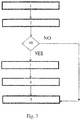
- Figure 3 shows a method of functioning of the system for managing the recharge of an electric or hybrid vehicle according to the present invention.
- step 1 the cable connection to the vehicle takes place, in step 2, the proximity resistance value Rc is measured, in step 10, if such a value does not belong to the list of values predetermined by the standard IEC 61851-1, then (NO) next is step 5, that is to say, setting of a maximum value, for the battery charger, of a recharge current of the batteries as a function of only the cable characteristics.
- the logical block RCU If, on the other hand, the proximity resistance value RC belongs to the list of values predetermined by the standard IEC 61851-1 then, in step 3, the logical block RCU is enabled, in step 4, the logical block RCU asks the processing unit on board the recharge station to negotiate the maximum current deliverable by the station, in step 5, the RCU transmits the maximum current value negotiated to the VMU and the VMU sets up the functioning of the battery charger according to such a negotiated value and to the performance characteristics of the cable.
- An electric cable according to the present invention therefore, has at a first end a single-phase or three-phase plug of the traditional five-pole type, i.e. with 3F + N + PE, while at a second end it is provided with a plug having 7 pins, as specified by the standards IEC 61851-2 of type 2 and/or 3, in which the pilot pin is insulated and the proximity pin is connected to the earth conductor PE by means of a proximity resistance Rc of predefined value, different from what predefined by the standard IEC 61851-1.
- the present invention may be advantageously implemented by a computer program which comprises coding means for implementing one or more steps of the method, when this program is run on a computer. Therefore, it is understood that the scope of protection extends to said computer program and moreover to computer-readable means which comprise a recorded message, said computer-readable means comprising program coding means for implementing one or more steps of the method when said program is run on a computer.
Landscapes
- Engineering & Computer Science (AREA)
- Power Engineering (AREA)
- Transportation (AREA)
- Mechanical Engineering (AREA)
- Life Sciences & Earth Sciences (AREA)
- Sustainable Development (AREA)
- Sustainable Energy (AREA)
- Electric Propulsion And Braking For Vehicles (AREA)
- Charge And Discharge Circuits For Batteries Or The Like (AREA)
- Hybrid Electric Vehicles (AREA)
- Arrangement Or Mounting Of Propulsion Units For Vehicles (AREA)
- Secondary Cells (AREA)
Claims (11)
- Ein System zur Verwaltung des Ladens eines elektrischen Fahrzeugs oder eines Hybridfahrzeugs (HEV), umfassend- erste Mittel (VCU) zur Messung eines Wertes eines Näherungswiderstands (Rc) eines Ladekabels (Ca), welcher die Leistungscharakteristika des Ladekabels (Ca) angibt,- zweite Mittel (RCU) zur Verhandlung eines Wertes eines Ladestroms mit einer Ladestation (RS),- ein Batterieladegerät (AC/DC), welches von den ersten Mitteln (VCU) auf Basis der Leistungscharakteristika des Ladekabels (Ca) und des verhandelten Ladestromwertes gesteuert wird,
wobei die ersten Mittel (VCU) ausgeführt sind, um die Funktionsfähigkeit der zweiten Mittel zu unterbinden oder um die zweiten Prozessmittel zu ignorieren, wenn der Näherungswiderstandswert mindestens einen vordefinierten Wert aus einem ersten Satz an Werten einnimmt,
welches System dadurch gekennzeichnet ist, dass die ersten Mittel (VCU) weiter ausgeführt sind, um:den Wert des Näherungswiderstands (Rc) zu messen; undfalls dieser Wert nicht zu der Liste der vordefinierten Werte der Norm 61851-1 gehört (NEIN), dann einen Maximalwert eines Ladestroms als eine Funktion der Leistungscharakteristika nur des Ladekabels (Ca) festzulegen,andernfalls (SI), falls der Wert des Näherungswiderstands (Rc) zu der Liste der vordefinierten Werte der Norm IEC 61851-1 gehört: einen Maximalstrom, welcher von der Ladestation lieferbar ist, zu verhandeln, und dann einen Ladestrom als eine Funktion des verhandelten Maximalstroms und der Leistungscharakteristika des Kabels festzulegen. - Ein System nach Anspruch 1, ausgeführt um nach dem Modus 3, der durch die Norm IEC 61851 festgelegt wird, zu arbeiten, wenn der Näherungswiderstandswert mit einem Wert eines zweiten vordefinierten Wertsatzes, welcher durch die Norm IEC 61851 selbst bestimmt wird, übereinstimmt, wobei eine Schnittmenge zwischen dem ersten und dem zweiten Satz leer/null ist.
- Ein System nach einem der vorstehenden Ansprüche, wobei der vordefinierte Wert des Näherungswiderstands mit der Leistung des Kabels und den Charakteristika des jeweiligen Stromnetzes verknüpft ist.
- Ein System nach Anspruch 3, wobei mindestens ein vordefinierter Widerstandwert Folgendem zugeordnet ist:- einer Verbindung des Fahrzeugs (HEV) zu einem privaten, dreiphasigen Stromnetz, ohne jegliche Ladestation, mit maximaler Stromstärke von 32A und/oder- einer Verbindung zu einem privaten, einphasigen Stromnetz, ohne jegliche Ladestation, mit maximaler Stromstärke von 16A und/oder- einer Verbindung zu einem privaten Stromnetz des einphasigen 10A-Typs, ohne jegliche Ladestation, mit maximaler Stromstärke von 10A.
- Ein Verfahren zum Betrieb eines Systems für die Verwaltung des Ladens eines elektrischen Fahrzeugs oder eines Hybridfahrzeugs (HEV), umfassend:- erste Mittel (VCU) zur Messung eines Wertes eines Näherungswiderstands (Rc) eines Ladekabels (Ca), welcher die Leistungscharakteristika des Ladekabels (Ca) angibt,- zweite Mittel (RCU) zur Verhandlung eines Wertes eines Ladestroms mit einer Ladestation (RS),- ein Batterieladegerät (AC/DC), welches von den ersten Mitteln (VCU) auf Basis der Leistungscharakteristika des Ladekabels (Ca) und des verhandelten Ladestromwertes verwaltet wird,
wobei das Verfahren den Schritt umfasst, die Funktionsfähigkeit der zweiten Mittel zu unterbinden oder die zweiten Prozessmittel zu ignorieren, wenn der Näherungswiderstandswert mindestens einen vordefinierten Wert aus einem ersten Satz an Werten einnimmt,
dadurch gekennzeichnet, dass es weiter die Schritte umfasst:den Wert des Näherungswiderstands (Rc) zu messen; undfalls dieser Wert nicht zu der Liste der vordefinierten Werte der Norm 61851-1 gehört (NEIN), dann einen Maximalwert eines Ladestroms als eine Funktion der Leistungscharakteristika nur des Ladekabels (CA) festzulegen,andernfalls (SI), falls der Wert des Näherungswiderstands (Rc) zu der Liste der vordefinierten Werte der Norm IEC 61851-1 gehört: einen Maximalstrom, welcher von der Ladestation lieferbar ist, mit dieser zu verhandeln, und dann einen Ladestroms als eine Funktion des verhandelten Maximalstroms und der Leistungscharakteristika des Kabels festzulegen. - Verfahren nach Anspruch 5, wobei das System mit dem Modus 3 definiert durch die Norm IEC 61851 konform ist, wenn der Näherungswiderstandswert mit einem Wert eines zweiten vordefinierten Wertsatzes, welcher durch die Norm IEC 61851 selbst bestimmt wird, übereinstimmt, wobei eine Schnittmenge zwischen dem ersten und dem zweiten Satz leer/null ist.
- Ein Verfahren nach einem der vorstehenden Ansprüche, wobei der vordefinierte Wert des Näherungswiderstands mit der Leistung des Kabels und den Charakteristika des jeweiligen Stromnetzes verknüpft ist.
- Ein Verfahren nach Anspruch 7, wobei mindestens ein vordefinierter Widerstandwert Folgendem zugeordnet ist:- einer Verbindung des Fahrzeugs (HEV) zu einem privaten, dreiphasigen Stromnetz, ohne jegliche Ladestation, mit maximaler Stromstärke von 32A und/oder- einer Verbindung zu einem privaten, einphasigen Stromnetz, ohne jegliche Ladestation, mit maximaler Stromstärke von 16A und/oder- einer Verbindung zu einem privaten Stromnetz des einphasigen 10A-Typs, ohne jegliche Ladestation, mit maximaler Stromstärke von 10A.
- Hybrid- oder elektrisches Fahrzeug (HEV), umfassend ein System für das Verwalten der Ladung nach einem der Ansprüche 1 bis 4.
- Computerprogramm, umfassend Programmcodemittel, ausgeführt, um alle Schritte der Ansprüche 5 bis 8 auszuführen, wenn das Programm auf einem Rechner ausgeführt wird.
- Computerlesbare Mittel, umfassend ein aufgezeichnetes Programm, wobei die computerlesbaren Mittel Programmcodemittel umfassen, welche ausgeführt sind, um die Schritte der Ansprüche 5 bis 8 auszuführen, wenn das Programm auf einem Rechner ausgeführt wird.
Applications Claiming Priority (2)
| Application Number | Priority Date | Filing Date | Title |
|---|---|---|---|
| IT002006A ITMI20132006A1 (it) | 2013-12-02 | 2013-12-02 | Sistema di gestione della ricarica di un veicolo elettrico o ibrido |
| PCT/IB2014/066522 WO2015083080A1 (en) | 2013-12-02 | 2014-12-02 | System for managing the recharge of an electric or hybrid vehicle |
Publications (2)
| Publication Number | Publication Date |
|---|---|
| EP3077245A1 EP3077245A1 (de) | 2016-10-12 |
| EP3077245B1 true EP3077245B1 (de) | 2020-02-26 |
Family
ID=50033627
Family Applications (1)
| Application Number | Title | Priority Date | Filing Date |
|---|---|---|---|
| EP14828302.1A Active EP3077245B1 (de) | 2013-12-02 | 2014-12-02 | Aufladungsverwaltungssystem für elektrisches oder hybridfahrzeug |
Country Status (8)
| Country | Link |
|---|---|
| EP (1) | EP3077245B1 (de) |
| JP (1) | JP6629203B2 (de) |
| CN (1) | CN105980195B (de) |
| AU (1) | AU2014358752B2 (de) |
| BR (1) | BR112016012597B1 (de) |
| ES (1) | ES2786300T3 (de) |
| IT (1) | ITMI20132006A1 (de) |
| WO (1) | WO2015083080A1 (de) |
Cited By (1)
| Publication number | Priority date | Publication date | Assignee | Title |
|---|---|---|---|---|
| WO2025185885A1 (en) * | 2024-03-08 | 2025-09-12 | Robert Bosch Gmbh | A charging control unit (ccu) for an electric vehicle |
Families Citing this family (1)
| Publication number | Priority date | Publication date | Assignee | Title |
|---|---|---|---|---|
| CN110271439B (zh) * | 2019-05-29 | 2020-09-25 | 恒大智慧充电科技有限公司 | 充电装置、充电方法、计算机设备及存储介质 |
Family Cites Families (6)
| Publication number | Priority date | Publication date | Assignee | Title |
|---|---|---|---|---|
| DE102010053072A1 (de) * | 2010-12-01 | 2011-08-25 | Daimler AG, 70327 | Verbindungsvorrichtung sowie Verfahren zum Begrenzen eines maximalen elektrischen Stroms |
| DE102010053074A1 (de) * | 2010-12-01 | 2011-08-25 | Daimler AG, 70327 | Ladekabelvorrichtung sowie Verfahren zum Begrenzen eines maximalen elektrischen Stroms |
| CN201985554U (zh) * | 2010-12-08 | 2011-09-21 | 夏正奎 | 锂离子动力电池主动式自管理充电装置 |
| DE102011003518B4 (de) * | 2011-02-02 | 2013-01-03 | Siemens Aktiengesellschaft | Verfahren zum Schutz eines Ladekabels und Ladeeinrichtung |
| JP5416735B2 (ja) * | 2011-04-28 | 2014-02-12 | 株式会社日立製作所 | 電力監視制御装置および電力監視制御システム |
| US9184792B2 (en) * | 2012-04-05 | 2015-11-10 | Mitsubishi Electric Corporation | Charging communication system and charging equipment |
-
2013
- 2013-12-02 IT IT002006A patent/ITMI20132006A1/it unknown
-
2014
- 2014-12-02 ES ES14828302T patent/ES2786300T3/es active Active
- 2014-12-02 AU AU2014358752A patent/AU2014358752B2/en active Active
- 2014-12-02 EP EP14828302.1A patent/EP3077245B1/de active Active
- 2014-12-02 CN CN201480066015.6A patent/CN105980195B/zh active Active
- 2014-12-02 JP JP2016536245A patent/JP6629203B2/ja active Active
- 2014-12-02 BR BR112016012597-5A patent/BR112016012597B1/pt active IP Right Grant
- 2014-12-02 WO PCT/IB2014/066522 patent/WO2015083080A1/en not_active Ceased
Non-Patent Citations (1)
| Title |
|---|
| None * |
Cited By (1)
| Publication number | Priority date | Publication date | Assignee | Title |
|---|---|---|---|---|
| WO2025185885A1 (en) * | 2024-03-08 | 2025-09-12 | Robert Bosch Gmbh | A charging control unit (ccu) for an electric vehicle |
Also Published As
| Publication number | Publication date |
|---|---|
| AU2014358752B2 (en) | 2019-09-12 |
| CN105980195B (zh) | 2019-04-19 |
| AU2014358752A1 (en) | 2016-06-23 |
| ES2786300T3 (es) | 2020-10-09 |
| JP2017501669A (ja) | 2017-01-12 |
| BR112016012597A8 (pt) | 2017-11-21 |
| EP3077245A1 (de) | 2016-10-12 |
| BR112016012597B1 (pt) | 2022-05-24 |
| BR112016012597A2 (pt) | 2017-08-08 |
| ITMI20132006A1 (it) | 2015-06-03 |
| JP6629203B2 (ja) | 2020-01-15 |
| CN105980195A (zh) | 2016-09-28 |
| WO2015083080A1 (en) | 2015-06-11 |
Similar Documents
| Publication | Publication Date | Title |
|---|---|---|
| KR102518036B1 (ko) | 전기 자동차의 충전 장치 및 충전 방법 | |
| CN104816642B (zh) | 便携式电气化车辆能量传递装置和方法 | |
| US9227519B2 (en) | Method and system for communication between a vehicle and a charging station for locking and unlocking mechanical charging cable coupling | |
| FI3688858T3 (fi) | Modulaarinen laite useiden sähköajoneuvojen ajassa siirretyksi lataamiseksi yhdellä latausasemalla | |
| US9071074B2 (en) | Multi-standard, alternating current or direct current compatible electric vehicle supply equipment | |
| CN106585393B (zh) | 用于电动车辆电力传输系统的安全方法和装置 | |
| CN106853778B (zh) | 用于发现evse的pd的方法和装置以及secc的操作方法 | |
| US11299058B2 (en) | Arrangement consisting of a motor vehicle and a connecting means, motor vehicle and connecting means | |
| EP2587615B1 (de) | System, Ladevorrichtung und Verfahren zum Liefern von Strom an eine Stromspeichervorrichtung | |
| WO2017022572A1 (ja) | 車載充電システム | |
| CN107848432A (zh) | 用于对电动车辆充电的装置和方法 | |
| US20200076217A1 (en) | Micro-grid smart output adaptor | |
| US12134327B2 (en) | Function extension module for charging stations | |
| EP3998691B1 (de) | Ladevorrichtung, system und verfahren zur steuerung einer ladevorrichtung | |
| JP7704231B2 (ja) | 車両制御装置、車両、電力供給システム、プログラム、放電コネクタ、電力設備および電力供給方法 | |
| JP2022139080A (ja) | 車両の充電制御方法および充電制御装置 | |
| JP2013051780A (ja) | 車両用充電システムおよび車両用充電ケーブル | |
| EP3077245B1 (de) | Aufladungsverwaltungssystem für elektrisches oder hybridfahrzeug | |
| KR102518037B1 (ko) | 전기 자동차의 충전 장치 및 그의 통신 방법 | |
| KR20210082763A (ko) | 마스터 배터리 및 슬레이브 배터리를 동시에 충전하는 전기자동차 충전 방법 | |
| WO2025046150A1 (en) | Improvements in or relating to electric vehicle charging | |
| EP4538101A1 (de) | Vorrichtung, verfahren und system zum laden mehrerer elektrofahrzeuge | |
| Harper | Development and implementation of sae dc charging digital communication for plug-in electric vehicle dc charging | |
| Dhaliwal et al. | Survey on protocols and standards used by electric vehicles | |
| EP4624224A1 (de) | Integriertes steuerungssystem für ein elektrofahrzeug und zugehöriges verfahren |
Legal Events
| Date | Code | Title | Description |
|---|---|---|---|
| PUAI | Public reference made under article 153(3) epc to a published international application that has entered the european phase |
Free format text: ORIGINAL CODE: 0009012 |
|
| 17P | Request for examination filed |
Effective date: 20160620 |
|
| AK | Designated contracting states |
Kind code of ref document: A1 Designated state(s): AL AT BE BG CH CY CZ DE DK EE ES FI FR GB GR HR HU IE IS IT LI LT LU LV MC MK MT NL NO PL PT RO RS SE SI SK SM TR |
|
| AX | Request for extension of the european patent |
Extension state: BA ME |
|
| DAX | Request for extension of the european patent (deleted) | ||
| STAA | Information on the status of an ep patent application or granted ep patent |
Free format text: STATUS: EXAMINATION IS IN PROGRESS |
|
| 17Q | First examination report despatched |
Effective date: 20190503 |
|
| GRAP | Despatch of communication of intention to grant a patent |
Free format text: ORIGINAL CODE: EPIDOSNIGR1 |
|
| STAA | Information on the status of an ep patent application or granted ep patent |
Free format text: STATUS: GRANT OF PATENT IS INTENDED |
|
| RIC1 | Information provided on ipc code assigned before grant |
Ipc: B60L 3/04 20060101ALI20190812BHEP Ipc: B60L 3/12 20060101ALI20190812BHEP Ipc: H02J 7/04 20060101ALI20190812BHEP Ipc: B60L 53/63 20190101ALI20190812BHEP Ipc: B60L 3/00 20190101AFI20190812BHEP Ipc: B60L 53/16 20190101ALI20190812BHEP Ipc: B60L 53/30 20190101ALI20190812BHEP Ipc: B60L 53/18 20190101ALI20190812BHEP |
|
| INTG | Intention to grant announced |
Effective date: 20190917 |
|
| GRAS | Grant fee paid |
Free format text: ORIGINAL CODE: EPIDOSNIGR3 |
|
| GRAA | (expected) grant |
Free format text: ORIGINAL CODE: 0009210 |
|
| STAA | Information on the status of an ep patent application or granted ep patent |
Free format text: STATUS: THE PATENT HAS BEEN GRANTED |
|
| AK | Designated contracting states |
Kind code of ref document: B1 Designated state(s): AL AT BE BG CH CY CZ DE DK EE ES FI FR GB GR HR HU IE IS IT LI LT LU LV MC MK MT NL NO PL PT RO RS SE SI SK SM TR |
|
| REG | Reference to a national code |
Ref country code: GB Ref legal event code: FG4D |
|
| REG | Reference to a national code |
Ref country code: CH Ref legal event code: EP |
|
| REG | Reference to a national code |
Ref country code: AT Ref legal event code: REF Ref document number: 1237204 Country of ref document: AT Kind code of ref document: T Effective date: 20200315 |
|
| REG | Reference to a national code |
Ref country code: IE Ref legal event code: FG4D |
|
| REG | Reference to a national code |
Ref country code: DE Ref legal event code: R096 Ref document number: 602014061619 Country of ref document: DE |
|
| PG25 | Lapsed in a contracting state [announced via postgrant information from national office to epo] |
Ref country code: RS Free format text: LAPSE BECAUSE OF FAILURE TO SUBMIT A TRANSLATION OF THE DESCRIPTION OR TO PAY THE FEE WITHIN THE PRESCRIBED TIME-LIMIT Effective date: 20200226 Ref country code: NO Free format text: LAPSE BECAUSE OF FAILURE TO SUBMIT A TRANSLATION OF THE DESCRIPTION OR TO PAY THE FEE WITHIN THE PRESCRIBED TIME-LIMIT Effective date: 20200526 Ref country code: FI Free format text: LAPSE BECAUSE OF FAILURE TO SUBMIT A TRANSLATION OF THE DESCRIPTION OR TO PAY THE FEE WITHIN THE PRESCRIBED TIME-LIMIT Effective date: 20200226 |
|
| REG | Reference to a national code |
Ref country code: NL Ref legal event code: MP Effective date: 20200226 |
|
| REG | Reference to a national code |
Ref country code: LT Ref legal event code: MG4D |
|
| PG25 | Lapsed in a contracting state [announced via postgrant information from national office to epo] |
Ref country code: SE Free format text: LAPSE BECAUSE OF FAILURE TO SUBMIT A TRANSLATION OF THE DESCRIPTION OR TO PAY THE FEE WITHIN THE PRESCRIBED TIME-LIMIT Effective date: 20200226 Ref country code: LV Free format text: LAPSE BECAUSE OF FAILURE TO SUBMIT A TRANSLATION OF THE DESCRIPTION OR TO PAY THE FEE WITHIN THE PRESCRIBED TIME-LIMIT Effective date: 20200226 Ref country code: HR Free format text: LAPSE BECAUSE OF FAILURE TO SUBMIT A TRANSLATION OF THE DESCRIPTION OR TO PAY THE FEE WITHIN THE PRESCRIBED TIME-LIMIT Effective date: 20200226 Ref country code: GR Free format text: LAPSE BECAUSE OF FAILURE TO SUBMIT A TRANSLATION OF THE DESCRIPTION OR TO PAY THE FEE WITHIN THE PRESCRIBED TIME-LIMIT Effective date: 20200527 Ref country code: IS Free format text: LAPSE BECAUSE OF FAILURE TO SUBMIT A TRANSLATION OF THE DESCRIPTION OR TO PAY THE FEE WITHIN THE PRESCRIBED TIME-LIMIT Effective date: 20200626 Ref country code: BG Free format text: LAPSE BECAUSE OF FAILURE TO SUBMIT A TRANSLATION OF THE DESCRIPTION OR TO PAY THE FEE WITHIN THE PRESCRIBED TIME-LIMIT Effective date: 20200526 |
|
| PG25 | Lapsed in a contracting state [announced via postgrant information from national office to epo] |
Ref country code: NL Free format text: LAPSE BECAUSE OF FAILURE TO SUBMIT A TRANSLATION OF THE DESCRIPTION OR TO PAY THE FEE WITHIN THE PRESCRIBED TIME-LIMIT Effective date: 20200226 |
|
| REG | Reference to a national code |
Ref country code: ES Ref legal event code: FG2A Ref document number: 2786300 Country of ref document: ES Kind code of ref document: T3 Effective date: 20201009 |
|
| PG25 | Lapsed in a contracting state [announced via postgrant information from national office to epo] |
Ref country code: DK Free format text: LAPSE BECAUSE OF FAILURE TO SUBMIT A TRANSLATION OF THE DESCRIPTION OR TO PAY THE FEE WITHIN THE PRESCRIBED TIME-LIMIT Effective date: 20200226 Ref country code: SK Free format text: LAPSE BECAUSE OF FAILURE TO SUBMIT A TRANSLATION OF THE DESCRIPTION OR TO PAY THE FEE WITHIN THE PRESCRIBED TIME-LIMIT Effective date: 20200226 Ref country code: EE Free format text: LAPSE BECAUSE OF FAILURE TO SUBMIT A TRANSLATION OF THE DESCRIPTION OR TO PAY THE FEE WITHIN THE PRESCRIBED TIME-LIMIT Effective date: 20200226 Ref country code: SM Free format text: LAPSE BECAUSE OF FAILURE TO SUBMIT A TRANSLATION OF THE DESCRIPTION OR TO PAY THE FEE WITHIN THE PRESCRIBED TIME-LIMIT Effective date: 20200226 Ref country code: LT Free format text: LAPSE BECAUSE OF FAILURE TO SUBMIT A TRANSLATION OF THE DESCRIPTION OR TO PAY THE FEE WITHIN THE PRESCRIBED TIME-LIMIT Effective date: 20200226 Ref country code: PT Free format text: LAPSE BECAUSE OF FAILURE TO SUBMIT A TRANSLATION OF THE DESCRIPTION OR TO PAY THE FEE WITHIN THE PRESCRIBED TIME-LIMIT Effective date: 20200719 Ref country code: RO Free format text: LAPSE BECAUSE OF FAILURE TO SUBMIT A TRANSLATION OF THE DESCRIPTION OR TO PAY THE FEE WITHIN THE PRESCRIBED TIME-LIMIT Effective date: 20200226 Ref country code: CZ Free format text: LAPSE BECAUSE OF FAILURE TO SUBMIT A TRANSLATION OF THE DESCRIPTION OR TO PAY THE FEE WITHIN THE PRESCRIBED TIME-LIMIT Effective date: 20200226 |
|
| REG | Reference to a national code |
Ref country code: AT Ref legal event code: MK05 Ref document number: 1237204 Country of ref document: AT Kind code of ref document: T Effective date: 20200226 |
|
| REG | Reference to a national code |
Ref country code: DE Ref legal event code: R097 Ref document number: 602014061619 Country of ref document: DE |
|
| PLBE | No opposition filed within time limit |
Free format text: ORIGINAL CODE: 0009261 |
|
| STAA | Information on the status of an ep patent application or granted ep patent |
Free format text: STATUS: NO OPPOSITION FILED WITHIN TIME LIMIT |
|
| PG25 | Lapsed in a contracting state [announced via postgrant information from national office to epo] |
Ref country code: AT Free format text: LAPSE BECAUSE OF FAILURE TO SUBMIT A TRANSLATION OF THE DESCRIPTION OR TO PAY THE FEE WITHIN THE PRESCRIBED TIME-LIMIT Effective date: 20200226 |
|
| 26N | No opposition filed |
Effective date: 20201127 |
|
| PG25 | Lapsed in a contracting state [announced via postgrant information from national office to epo] |
Ref country code: PL Free format text: LAPSE BECAUSE OF FAILURE TO SUBMIT A TRANSLATION OF THE DESCRIPTION OR TO PAY THE FEE WITHIN THE PRESCRIBED TIME-LIMIT Effective date: 20200226 Ref country code: SI Free format text: LAPSE BECAUSE OF FAILURE TO SUBMIT A TRANSLATION OF THE DESCRIPTION OR TO PAY THE FEE WITHIN THE PRESCRIBED TIME-LIMIT Effective date: 20200226 |
|
| REG | Reference to a national code |
Ref country code: CH Ref legal event code: PL |
|
| PG25 | Lapsed in a contracting state [announced via postgrant information from national office to epo] |
Ref country code: MC Free format text: LAPSE BECAUSE OF FAILURE TO SUBMIT A TRANSLATION OF THE DESCRIPTION OR TO PAY THE FEE WITHIN THE PRESCRIBED TIME-LIMIT Effective date: 20200226 |
|
| REG | Reference to a national code |
Ref country code: BE Ref legal event code: MM Effective date: 20201231 |
|
| PG25 | Lapsed in a contracting state [announced via postgrant information from national office to epo] |
Ref country code: IE Free format text: LAPSE BECAUSE OF NON-PAYMENT OF DUE FEES Effective date: 20201202 Ref country code: LU Free format text: LAPSE BECAUSE OF NON-PAYMENT OF DUE FEES Effective date: 20201202 |
|
| PG25 | Lapsed in a contracting state [announced via postgrant information from national office to epo] |
Ref country code: LI Free format text: LAPSE BECAUSE OF NON-PAYMENT OF DUE FEES Effective date: 20201231 Ref country code: CH Free format text: LAPSE BECAUSE OF NON-PAYMENT OF DUE FEES Effective date: 20201231 |
|
| PG25 | Lapsed in a contracting state [announced via postgrant information from national office to epo] |
Ref country code: TR Free format text: LAPSE BECAUSE OF FAILURE TO SUBMIT A TRANSLATION OF THE DESCRIPTION OR TO PAY THE FEE WITHIN THE PRESCRIBED TIME-LIMIT Effective date: 20200226 Ref country code: MT Free format text: LAPSE BECAUSE OF FAILURE TO SUBMIT A TRANSLATION OF THE DESCRIPTION OR TO PAY THE FEE WITHIN THE PRESCRIBED TIME-LIMIT Effective date: 20200226 Ref country code: CY Free format text: LAPSE BECAUSE OF FAILURE TO SUBMIT A TRANSLATION OF THE DESCRIPTION OR TO PAY THE FEE WITHIN THE PRESCRIBED TIME-LIMIT Effective date: 20200226 |
|
| PG25 | Lapsed in a contracting state [announced via postgrant information from national office to epo] |
Ref country code: MK Free format text: LAPSE BECAUSE OF FAILURE TO SUBMIT A TRANSLATION OF THE DESCRIPTION OR TO PAY THE FEE WITHIN THE PRESCRIBED TIME-LIMIT Effective date: 20200226 Ref country code: AL Free format text: LAPSE BECAUSE OF FAILURE TO SUBMIT A TRANSLATION OF THE DESCRIPTION OR TO PAY THE FEE WITHIN THE PRESCRIBED TIME-LIMIT Effective date: 20200226 |
|
| PG25 | Lapsed in a contracting state [announced via postgrant information from national office to epo] |
Ref country code: BE Free format text: LAPSE BECAUSE OF NON-PAYMENT OF DUE FEES Effective date: 20201231 |
|
| P01 | Opt-out of the competence of the unified patent court (upc) registered |
Effective date: 20230523 |
|
| PGFP | Annual fee paid to national office [announced via postgrant information from national office to epo] |
Ref country code: GB Payment date: 20251223 Year of fee payment: 12 |
|
| PGFP | Annual fee paid to national office [announced via postgrant information from national office to epo] |
Ref country code: IT Payment date: 20251120 Year of fee payment: 12 |
|
| PGFP | Annual fee paid to national office [announced via postgrant information from national office to epo] |
Ref country code: FR Payment date: 20251223 Year of fee payment: 12 |
|
| PGFP | Annual fee paid to national office [announced via postgrant information from national office to epo] |
Ref country code: ES Payment date: 20260122 Year of fee payment: 12 |
|
| PGFP | Annual fee paid to national office [announced via postgrant information from national office to epo] |
Ref country code: DE Payment date: 20251229 Year of fee payment: 12 |