EP3076900B1 - Asymmetric opening and closing prosthetic valve leaflet - Google Patents
Asymmetric opening and closing prosthetic valve leaflet Download PDFInfo
- Publication number
- EP3076900B1 EP3076900B1 EP14821950.4A EP14821950A EP3076900B1 EP 3076900 B1 EP3076900 B1 EP 3076900B1 EP 14821950 A EP14821950 A EP 14821950A EP 3076900 B1 EP3076900 B1 EP 3076900B1
- Authority
- EP
- European Patent Office
- Prior art keywords
- leaflet
- side region
- window
- frame
- region
- Prior art date
- Legal status (The legal status is an assumption and is not a legal conclusion. Google has not performed a legal analysis and makes no representation as to the accuracy of the status listed.)
- Active
Links
Images


Classifications
-
- A—HUMAN NECESSITIES
- A61—MEDICAL OR VETERINARY SCIENCE; HYGIENE
- A61F—FILTERS IMPLANTABLE INTO BLOOD VESSELS; PROSTHESES; DEVICES PROVIDING PATENCY TO, OR PREVENTING COLLAPSING OF, TUBULAR STRUCTURES OF THE BODY, e.g. STENTS; ORTHOPAEDIC, NURSING OR CONTRACEPTIVE DEVICES; FOMENTATION; TREATMENT OR PROTECTION OF EYES OR EARS; BANDAGES, DRESSINGS OR ABSORBENT PADS; FIRST-AID KITS
- A61F2/00—Filters implantable into blood vessels; Prostheses, i.e. artificial substitutes or replacements for parts of the body; Appliances for connecting them with the body; Devices providing patency to, or preventing collapsing of, tubular structures of the body, e.g. stents
- A61F2/02—Prostheses implantable into the body
- A61F2/24—Heart valves ; Vascular valves, e.g. venous valves; Heart implants, e.g. passive devices for improving the function of the native valve or the heart muscle; Transmyocardial revascularisation [TMR] devices; Valves implantable in the body
- A61F2/2412—Heart valves ; Vascular valves, e.g. venous valves; Heart implants, e.g. passive devices for improving the function of the native valve or the heart muscle; Transmyocardial revascularisation [TMR] devices; Valves implantable in the body with soft flexible valve members, e.g. tissue valves shaped like natural valves
- A61F2/2418—Scaffolds therefor, e.g. support stents
-
- A—HUMAN NECESSITIES
- A61—MEDICAL OR VETERINARY SCIENCE; HYGIENE
- A61F—FILTERS IMPLANTABLE INTO BLOOD VESSELS; PROSTHESES; DEVICES PROVIDING PATENCY TO, OR PREVENTING COLLAPSING OF, TUBULAR STRUCTURES OF THE BODY, e.g. STENTS; ORTHOPAEDIC, NURSING OR CONTRACEPTIVE DEVICES; FOMENTATION; TREATMENT OR PROTECTION OF EYES OR EARS; BANDAGES, DRESSINGS OR ABSORBENT PADS; FIRST-AID KITS
- A61F2/00—Filters implantable into blood vessels; Prostheses, i.e. artificial substitutes or replacements for parts of the body; Appliances for connecting them with the body; Devices providing patency to, or preventing collapsing of, tubular structures of the body, e.g. stents
- A61F2/02—Prostheses implantable into the body
- A61F2/24—Heart valves ; Vascular valves, e.g. venous valves; Heart implants, e.g. passive devices for improving the function of the native valve or the heart muscle; Transmyocardial revascularisation [TMR] devices; Valves implantable in the body
- A61F2/2412—Heart valves ; Vascular valves, e.g. venous valves; Heart implants, e.g. passive devices for improving the function of the native valve or the heart muscle; Transmyocardial revascularisation [TMR] devices; Valves implantable in the body with soft flexible valve members, e.g. tissue valves shaped like natural valves
- A61F2/2415—Manufacturing methods
-
- A—HUMAN NECESSITIES
- A61—MEDICAL OR VETERINARY SCIENCE; HYGIENE
- A61F—FILTERS IMPLANTABLE INTO BLOOD VESSELS; PROSTHESES; DEVICES PROVIDING PATENCY TO, OR PREVENTING COLLAPSING OF, TUBULAR STRUCTURES OF THE BODY, e.g. STENTS; ORTHOPAEDIC, NURSING OR CONTRACEPTIVE DEVICES; FOMENTATION; TREATMENT OR PROTECTION OF EYES OR EARS; BANDAGES, DRESSINGS OR ABSORBENT PADS; FIRST-AID KITS
- A61F2210/00—Particular material properties of prostheses classified in groups A61F2/00 - A61F2/26 or A61F2/82 or A61F9/00 or A61F11/00 or subgroups thereof
- A61F2210/0076—Particular material properties of prostheses classified in groups A61F2/00 - A61F2/26 or A61F2/82 or A61F9/00 or A61F11/00 or subgroups thereof multilayered, e.g. laminated structures
-
- A—HUMAN NECESSITIES
- A61—MEDICAL OR VETERINARY SCIENCE; HYGIENE
- A61F—FILTERS IMPLANTABLE INTO BLOOD VESSELS; PROSTHESES; DEVICES PROVIDING PATENCY TO, OR PREVENTING COLLAPSING OF, TUBULAR STRUCTURES OF THE BODY, e.g. STENTS; ORTHOPAEDIC, NURSING OR CONTRACEPTIVE DEVICES; FOMENTATION; TREATMENT OR PROTECTION OF EYES OR EARS; BANDAGES, DRESSINGS OR ABSORBENT PADS; FIRST-AID KITS
- A61F2230/00—Geometry of prostheses classified in groups A61F2/00 - A61F2/26 or A61F2/82 or A61F9/00 or A61F11/00 or subgroups thereof
- A61F2230/0002—Two-dimensional shapes, e.g. cross-sections
- A61F2230/0004—Rounded shapes, e.g. with rounded corners
- A61F2230/0006—Rounded shapes, e.g. with rounded corners circular
-
- A—HUMAN NECESSITIES
- A61—MEDICAL OR VETERINARY SCIENCE; HYGIENE
- A61F—FILTERS IMPLANTABLE INTO BLOOD VESSELS; PROSTHESES; DEVICES PROVIDING PATENCY TO, OR PREVENTING COLLAPSING OF, TUBULAR STRUCTURES OF THE BODY, e.g. STENTS; ORTHOPAEDIC, NURSING OR CONTRACEPTIVE DEVICES; FOMENTATION; TREATMENT OR PROTECTION OF EYES OR EARS; BANDAGES, DRESSINGS OR ABSORBENT PADS; FIRST-AID KITS
- A61F2230/00—Geometry of prostheses classified in groups A61F2/00 - A61F2/26 or A61F2/82 or A61F9/00 or A61F11/00 or subgroups thereof
- A61F2230/0063—Three-dimensional shapes
- A61F2230/0071—Three-dimensional shapes spherical
-
- A—HUMAN NECESSITIES
- A61—MEDICAL OR VETERINARY SCIENCE; HYGIENE
- A61F—FILTERS IMPLANTABLE INTO BLOOD VESSELS; PROSTHESES; DEVICES PROVIDING PATENCY TO, OR PREVENTING COLLAPSING OF, TUBULAR STRUCTURES OF THE BODY, e.g. STENTS; ORTHOPAEDIC, NURSING OR CONTRACEPTIVE DEVICES; FOMENTATION; TREATMENT OR PROTECTION OF EYES OR EARS; BANDAGES, DRESSINGS OR ABSORBENT PADS; FIRST-AID KITS
- A61F2250/00—Special features of prostheses classified in groups A61F2/00 - A61F2/26 or A61F2/82 or A61F9/00 or A61F11/00 or subgroups thereof
- A61F2250/0014—Special features of prostheses classified in groups A61F2/00 - A61F2/26 or A61F2/82 or A61F9/00 or A61F11/00 or subgroups thereof having different values of a given property or geometrical feature, e.g. mechanical property or material property, at different locations within the same prosthesis
- A61F2250/0018—Special features of prostheses classified in groups A61F2/00 - A61F2/26 or A61F2/82 or A61F9/00 or A61F11/00 or subgroups thereof having different values of a given property or geometrical feature, e.g. mechanical property or material property, at different locations within the same prosthesis differing in elasticity, stiffness or compressibility
-
- A—HUMAN NECESSITIES
- A61—MEDICAL OR VETERINARY SCIENCE; HYGIENE
- A61F—FILTERS IMPLANTABLE INTO BLOOD VESSELS; PROSTHESES; DEVICES PROVIDING PATENCY TO, OR PREVENTING COLLAPSING OF, TUBULAR STRUCTURES OF THE BODY, e.g. STENTS; ORTHOPAEDIC, NURSING OR CONTRACEPTIVE DEVICES; FOMENTATION; TREATMENT OR PROTECTION OF EYES OR EARS; BANDAGES, DRESSINGS OR ABSORBENT PADS; FIRST-AID KITS
- A61F2250/00—Special features of prostheses classified in groups A61F2/00 - A61F2/26 or A61F2/82 or A61F9/00 or A61F11/00 or subgroups thereof
- A61F2250/0014—Special features of prostheses classified in groups A61F2/00 - A61F2/26 or A61F2/82 or A61F9/00 or A61F11/00 or subgroups thereof having different values of a given property or geometrical feature, e.g. mechanical property or material property, at different locations within the same prosthesis
- A61F2250/0029—Special features of prostheses classified in groups A61F2/00 - A61F2/26 or A61F2/82 or A61F9/00 or A61F11/00 or subgroups thereof having different values of a given property or geometrical feature, e.g. mechanical property or material property, at different locations within the same prosthesis differing in bending or flexure capacity
-
- A—HUMAN NECESSITIES
- A61—MEDICAL OR VETERINARY SCIENCE; HYGIENE
- A61F—FILTERS IMPLANTABLE INTO BLOOD VESSELS; PROSTHESES; DEVICES PROVIDING PATENCY TO, OR PREVENTING COLLAPSING OF, TUBULAR STRUCTURES OF THE BODY, e.g. STENTS; ORTHOPAEDIC, NURSING OR CONTRACEPTIVE DEVICES; FOMENTATION; TREATMENT OR PROTECTION OF EYES OR EARS; BANDAGES, DRESSINGS OR ABSORBENT PADS; FIRST-AID KITS
- A61F2250/00—Special features of prostheses classified in groups A61F2/00 - A61F2/26 or A61F2/82 or A61F9/00 or A61F11/00 or subgroups thereof
- A61F2250/0014—Special features of prostheses classified in groups A61F2/00 - A61F2/26 or A61F2/82 or A61F9/00 or A61F11/00 or subgroups thereof having different values of a given property or geometrical feature, e.g. mechanical property or material property, at different locations within the same prosthesis
- A61F2250/0036—Special features of prostheses classified in groups A61F2/00 - A61F2/26 or A61F2/82 or A61F9/00 or A61F11/00 or subgroups thereof having different values of a given property or geometrical feature, e.g. mechanical property or material property, at different locations within the same prosthesis differing in thickness
-
- Y—GENERAL TAGGING OF NEW TECHNOLOGICAL DEVELOPMENTS; GENERAL TAGGING OF CROSS-SECTIONAL TECHNOLOGIES SPANNING OVER SEVERAL SECTIONS OF THE IPC; TECHNICAL SUBJECTS COVERED BY FORMER USPC CROSS-REFERENCE ART COLLECTIONS [XRACs] AND DIGESTS
- Y10—TECHNICAL SUBJECTS COVERED BY FORMER USPC
- Y10T—TECHNICAL SUBJECTS COVERED BY FORMER US CLASSIFICATION
- Y10T29/00—Metal working
- Y10T29/49—Method of mechanical manufacture
- Y10T29/49826—Assembling or joining
- Y10T29/49895—Associating parts by use of aligning means [e.g., use of a drift pin or a "fixture"]
- Y10T29/49901—Sequentially associating parts on stationary aligning means
Definitions
- the present disclosure relates generally to prosthetic valves and more specifically, synthetic flexible leaflet-type prosthetic valve devices and methods.
- Bioprosthetic valves have been developed that attempt to mimic the function and performance of a native valve.
- Flexible leaflets are fabricated from biological tissue such as bovine pericardium.
- biological tissue such as bovine pericardium.
- the biological tissue is sewn onto a relatively rigid frame that supports the leaflets and provides dimensional stability when implanted.
- bioprosthetic valves can provide excellent hemodynamic and biomechanical performance in the short term, they are prone to calcification and cusp tears, among other failure modes, requiring reoperation and replacement.
- synthetic leaflet valve Attempts have been made to use synthetic materials, such as polyurethane, among others, as a substitute for the biological tissue, to provide a more durable flexible leaflet prosthetic valve, herein referred to as a synthetic leaflet valve (SLV).
- synthetic leaflet valves have not become a valid valve replacement option since they suffer premature failure, due to, among other things, suboptimal design and lack of a durable synthetic material.
- the leaflets move under the influence of fluid pressure.
- the leaflets open when the upstream fluid pressure exceeds the downstream fluid pressure and close when the downstream fluid pressure exceeds the upstream fluid pressure.
- the free edges of the leaflets coapt under the influence of downstream fluid pressure closing the valve to prevent downstream blood from flowing retrograde through the valve.
- leaflets do not open and close in a controlled manner.
- the durability of the leaflets is largely controlled by the character of bending exhibited by the leaflet during the opening-closing cycle. Small radius bends, creases and particularly intersecting creases, can produce high stress zones in the leaflet. These high stress zones can cause the formation of holes and tears under repetitive loading. If the leaflet bending is unrestricted, not only do creases form, but crease intersections lead to formation of large three dimensional structures (e.g., surface disruptions) that oppose bending and slow down the leaflet motion, both in opening and closing. This slow down of leaflet motion leads to an increase in closing volume; that is, the volume of blood that travels back through the valve during the closing phase in order to close the valve. It is advantageous to minimize closing volume.
- the flexible nature of the very flexible leaflet can create regions of blood pooling behind the leaflet when in the open position potentially causing blood clots to form at the leaflet base and near the attachment of the leaflet to the frame.
- US Patent Publication No. 2003/0097175 discloses a cardiac valve prosthesis having a frame and two or more leaflets attached to the frame.
- the leaflets are attached to the frame between posts, with a free edge which can seal the leaflets together when the valve is closed under back pressure.
- the leaflets are created in a mathematically defined shape allowing good wash-out of the whole leaflet orifice.
- US Patent No. 6 283 994 discloses a heart valve including a valve body and a plurality of flexible leaflets coupled to the valve body.
- the plurality of leaflets has an open position and a closed positon.
- Each of the plurality of leaflets comprises a belly when the plurality of leaflets are in their respective closed positions.
- the belly of one or more of the plurality of leaflets has a continuous curvature except for a noncontinuous portion.
- EP1318775 discloses a valve prosthesis including a plurality of commissures and improved reinforced polymer leaflets extending between the commissures.
- the leaflets are formed from a polymer and have a reinforced free edge.
- the reinforced free edge can include a reinforcing member.
- the leaflets have a reinforced free edge and a substantially uniform composition and thickness over the remaining body of the leaflet.
- the reinforced edge of the leaflet preferably has a flexural rigidity of no more than a factor of three greater than the unreinforced portion of the leaflet.
- a reinforcing polymer layer supplies increased strength to the leaflet.
- US Patent Publication No. 2013/0166021 discloses a thin, biocompatible, high strength, composite material that is suitable for use in various implanted configurations.
- the composite material maintains flexibility in high-cycle flexural applications, making it particularly applicable to high-flex implants such as heart pacing lead or heart valve leaflet.
- the composite material includes at least one porous expanded fluoropolymer layer and an elastomer substantially filling substantially all of the pores of the porous expanded fluoropolymer.
- US Patent No. 6 953 332 discloses improved dip coating methods and mandrels for forming polymer leaflets and valve prostheses generally involving one or more features on the mandrel that facilitate processing.
- the mandrel has a top surface and an outer surface comprising a plurality of ridges and contoured surfaces extending to the ridges.
- An edge on the mandrel separates the top surface and the contoured surfaces, with the mandrel edge corresponding to the free edge of the leaflet.
- the edge separating the top surface from the contoured surface is sharp.
- the polymer formed on the top surface can be efficiently separated from the remaining portions of the polymer structure to form the free edges of the leaflets.
- the invention is defined in the appended claims and relates to a prosthetic valve and a method of forming a prosthetic valve. Described embodiments are directed to flexible leaflet prosthetic heart valves in which the leaflets move into the open and closed position in a more controlled manner. Each leaflet moves asymmetrically in that a leaflet second side region of the leaflet initially moves toward the open position before a leaflet first side region and the leaflet first side region initially moves toward the closed position before the leaflet second side region. Further, in the fully open position, the leaflet first side region opens less than the leaflet second side region.
- Such asymmetric opening and final open position in synchrony with the other leaflets having the same motion and final open position creates spiral flow exiting the open valve that assists in creating an axial vortex flow that increases blood flow on the downstream side of the leaflet and thus reduces stagnation of the blood that might lead to thrombus formation.
- controlled asymmetric movement of the leaflet reduces closing volume by initiating closure on the leaflet first side region and finishing closures on the leaflet second side region, reducing leaflet buckling resistance to closure by, in part, allowing one region of the leaflet to close before another region.
- leaflet open position is controlled such that fluid flow across the leaflet first side region extends further into the valve orifice of the valve relative to the leaflet second side region to further expose the leaflet downstream side to the retrograde blood flow which increases washout of the blood from the leaflet downstream side and exposes the leaflet downstream side to improved reverse blood flow and to assist closing during the closing phase.
- Described embodiments are directed to flexible leaflet prosthetic valves in which the leaflets have regions of increased stiffness relative to other regions of the leaflet, so as to provide asymmetric opening and closing of the leaflet.
- the region of increased stiffness provides that the leaflet moves into the open and closed position in a more controlled manner. Further, the region of increased stiffness positions the open leaflet so as to provide an increased blood flow behind the leaflet and where the leaflet attaches to the leaflet frame.
- a prosthetic valve comprises a leaflet frame and a plurality of leaflets coupled to the leaflet frame.
- Each leaflet has a free edge, a leaflet first side, a leaflet second side, and a leaflet base therebetween.
- the leaflet first side, leaflet second side, and leaflet base are coupled to the leaflet frame.
- Each leaflet has a leaflet first side region adjacent the leaflet first side, a leaflet second side region adjacent the leaflet second side, and a leaflet central region therebetween and adjacent the leaflet base. At least a portion of the leaflet first side region has a stiffness that is greater than the stiffness of the leaflet second side region and leaflet central region.
- a prosthetic valve comprises a frame having a generally tubular shape with attached film.
- the frame defines a plurality of leaflet windows.
- Each leaflet window defines a leaflet window first side, a leaflet window second side, and a leaflet window base.
- the leaflet window first side and the leaflet window second side diverge from the leaflet window base.
- the film defines at least one leaflet extending from each of the leaflet windows.
- Each leaflet has a free edge, a leaflet first side that is coupled to the leaflet window first side, a leaflet second side that is coupled to the leaflet window second side, and a leaflet base therebetween that is coupled to the leaflet window base.
- Each leaflet has a leaflet first side region adjacent the leaflet first side and extending to a substantially axial line from the leaflet free edge to the intersection between the leaflet window first side and the leaflet window base, a leaflet second region adjacent the leaflet second side and extending to a substantially axial line from the leaflet free edge to the intersection between the leaflet window second side and the leaflet window base, and a leaflet central region therebetween and adjacent the leaflet free edge to the leaflet base.
- At least a portion of the leaflet first side region has a stiffness that is greater than the stiffness of the leaflet second region and leaflet central region.
- a prosthetic valve comprises a plurality of leaflets where each leaflet includes a leaflet first side region and a leaflet second side region opposite from the leaflet first side region.
- the leaflet first side region has a thickness that is thicker than a thickness of the second side region.
- embodiments herein may be described in connection with various principles and beliefs, the described embodiments should not be bound by theory.
- embodiments are described herein in connection with prosthetic valves, more specifically cardiac prosthetic valves.
- embodiments within the scope of this disclosure can be applied toward any valve or mechanism of similar structure and/or function.
- embodiments within the scope of this disclosure can be applied in non-cardiac applications.
- leaflet as used herein in the context of prosthetic valves is a component of a one-way valve wherein the leaflet is operable to move between an open and closed position under the influence of a pressure differential.
- the leaflet In an open position, the leaflet allows blood to flow through the valve.
- the leaflet In a closed position, the leaflet substantially blocks retrograde flow through the valve.
- each leaflet cooperates with at least one neighboring leaflet to block the retrograde flow of blood.
- the pressure differential in the blood is caused, for example, by the contraction of a ventricle or atrium of the heart, such pressure differential typically resulting from a fluid pressure building up on one side of the leaflets when closed.
- the leaflets As the pressure on an inflow side of the valve rises above the pressure on the outflow side of the valve, the leaflets opens and blood flows therethrough. As blood flows through the valve into a neighboring chamber or blood vessel, the pressure on the inflow side equalizes with the pressure on the outflow side. As the pressure on the outflow side of the valve rises above the blood pressure on the inflow side of the valve, the leaflet returns to the closed position generally preventing retrograde flow of blood through the valve.
- membrane refers to a sheet of material comprising a single composition, such as, but not limited to, expanded fluoropolymer.
- composite material refers to a combination of a membrane, such as, but not limited to, expanded fluoropolymer, and an elastomer, such as, but not limited to, a fluoroelastomer.
- the elastomer may be imbibed within a porous structure of the membrane, coated on one or both sides of the membrane, or a combination of coated on and imbibed within the membrane.
- laminate refers to multiple layers of membrane, composite material, or other materials, such as elastomer, and combinations thereof.
- film as used herein generically refers to one or more of the membrane, composite material, or laminate.
- biocompatible material as used herein generically refers to a film or a biological material, such as, but not limited to, bovine pericardium.
- leaflet window is defined as that space that a frame defines from which a leaflet extends.
- the leaflet may extend from frame elements or adjacent to frame elements and spaced apart therefrom.
- native valve orifice and tissue orifice refer to an anatomical structure into which a prosthetic valve may be placed.
- Such anatomical structure includes, but is not limited to, a location wherein a cardiac valve may or may not have been surgically removed.
- other anatomical structures that may receive a prosthetic valve include, but are not limited to, veins, arteries, ducts and shunts.
- a valve orifice or implant site may also refer to a location in a synthetic or biological conduit that may receive a valve for a particular purpose, and therefore the scope of the embodiments provided herein is not limited to valve replacement.
- Couple means to join, connect, attach, adhere, affix, or bond, whether directly or indirectly, and whether permanently or temporarily.
- Described embodiments are directed to flexible leaflet prosthetic valves in which the leaflets move into the open and closed position in a more controlled manner.
- the leaflets move in synchrony with each other.
- Each leaflet moves asymmetrically in that a leaflet second side region of the leaflet initially moves toward the open position before a leaflet first side region and the leaflet first side region initially moves toward the closed position before the leaflet second side region. Further, in the fully open position, the leaflet first side opens less than the leaflet second side.
- the leaflet first side region of one leaflet is adjacent to the leaflet second side region of an adjacent leaflet.
- Such asymmetric opening and final open position in synchrony with the other leaflets having the same motion and final open position, creates spiral flow exiting the open valve that assists in creating an axial vortex flow that increases blood flow on the downstream side of the leaflet and thus reduces stagnation of the blood that might lead to thrombus formation.
- controlled asymmetric movement of the leaflet reduces closing volume by initiating closure on the leaflet first side region and finishing closures on the leaflet second side region, reducing leaflet buckling resistance to closure by, in part, allowing one side region of the leaflet to close before another side region.
- the leaflet first side region is configured to be more resistant to motion as compared with the leaflet second side region.
- the resistant to motion may be affected in a number of ways, including, but not limited to, configuring the bending modulus of the leaflet material to have a higher bending modulus in the leaflet first side region as compared with the leaflet second side region.
- the resistant to motion may be affected in a number of ways, including, but not limited to, adding a reinforcing member that is separate from but coupled to the leaflet first side region.
- the resistant to motion may be affected in a number of ways, including, but not limited to, increasing the number of layers of a laminated composite that makes up the leaflet, and thus the thickness in the leaflet first side region as compared with the leaflet second side region.
- Embodiments provided herein address controlled leaflet opening and closing.
- Embodiments provided herein provide a feature of differing leaflet stiffness from one side region of the leaflet to the other side region. The less stiff side region of the leaflet will initiate opening before the stiffer side of the leaflet. Therefore, the leaflet will open asymmetrically with respect to the leaflet free edge rather than symmetrically as with a leaflet having a uniform or symmetric stiffness property. This asymmetric movement minimizes crease formation, which is of particular importance in thin, high-modulus leaflets.
- leaflet bending is unrestricted, not only may creases form, but crease intersections lead to formation of large three dimensional structures (e.g., surface disruptions) that oppose bending and slow down the leaflet motion, both in opening and closing.
- Embodiments provided herein control leaflet opening and to minimize crease formation provided by the controlled asymmetric opening and closing of the leaflet.
- Embodiments provided herein address blood pooling or stagnation that can lead to clot formation behind the leaflet and along the intersection of the leaflet and the frame when the leaflet is open.
- Embodiments provided herein provide a feature of differing leaflet stiffness from one side region of the leaflet to the other side region. The stiffer side region of the leaflet will open to a lesser extent than the less stiff side region. Since the stiffer side region of the leaflet does not open fully and therefore protrudes into the flow more so than the less stiff side region, retrograde blood flow may better extend behind the leaflet, the downstream side, producing a washing effect along the attachment of the leaflet to the frame and, in particular, at the base of the leaflet on the downstream side of the leaflet.
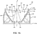
- FIG. 1A is a side view of a valve 100, in accordance with an embodiment.
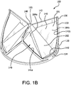
- FIG. 1B is a perspective view of the valve 100 of FIG. 1A .
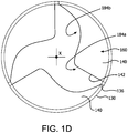
- FIGs. 1C , 1D and 1E are axial views of the valve 100 of FIG. 1A in an open, partially open, and closed configuration, respectively.
- the valve 100 comprises a leaflet frame 130 and film 160 that defines leaflets 140.
- the leaflets 140 are shown slightly open to better show the features but it is understood that a valve 100 that is fully closed will have the leaflet free edges 142 of the leaflets 140 coming together to coapt under the influence of downstream fluid pressure which results in closing the valve 100 to prevent downstream blood from flowing retrograde through the valve 100.
- the leaflet frame 130 is a generally tubular member, in accordance with an embodiment.
- the leaflet frame 130 comprises a leaflet frame first end 121a and a frame second end 121b opposite the leaflet frame first end 121a.
- the leaflet frame 130 comprises a leaflet frame outer surface 126a and a leaflet frame inner surface 126b opposite the leaflet frame outer surface 126a, as shown in FIG. 1A .
- the leaflet frame 130 defines commissure posts 136 that couple to the leaflet free edges 142.
- the commissure posts 136 are defined by a vertical element 122.
- strain relief frame covering 152 is shown in dashed line following the contour of the leaflet window 137.
- the strain relief frame covering 152 is a covering of film 160 that covers the leaflet frame 130 and extends about 0.5 mm to 1.0 mm into the leaflet window 137.
- the strain relief frame covering 152 provides a transition region that provides strain relief between the leaflet frame 130 and the leaflet 140.
- a leaflet 140 is shown in solid line to represent where the leaflet 140 is located within the leaflet window 137 and the leaflet reinforcing member 149, shown in dashed line, being within the leaflet first side region 184a.
- the leaflet frame 130 may comprise a cut tube, or any other element suitable for the particular purpose.
- the leaflet frame 130 may be etched, cut, laser cut, or stamped into a tube or a sheet of material, with the sheet then formed into a substantially cylindrical structure.
- the leaflet frame 130 can comprise any metallic or polymeric material that is biocompatible.
- the leaflet frame 130 can comprise a material, such as, but not limited to nitinol, cobalt-nickel alloy, stainless steel, or polypropylene, acetyl homopolymer, acetyl copolymer, ePTFE, other alloys or polymers, or any other biocompatible material having adequate physical and mechanical properties to function as described herein.
- the leaflet frame first end 121a further comprises commissure posts 136 extending from an apex of the leaflet frame elements defining substantially an isosceles trapezoid.
- the commissure post 136 may affect the leaflet free edge 142 so as to create a larger or wider coaptation region 146 between adjacent leaflet free edges 142.
- each leaflet 140 has substantially the shape of an isosceles trapezoid having a leaflet first side 141a and a leaflet second side 141b, a leaflet base 143 and a leaflet free edge 142 opposite the leaflet base 143, wherein the leaflet first side 141a and a leaflet second side 141b diverge from the leaflet base 143, wherein the leaflet base 143 is substantially flat, as shown in dashed lines in FIG. 2B .
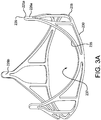
- FIG. 3 is a perspective view of a leaflet frame 230 that is a generally tubular member, in accordance with another embodiment.
- the leaflet frame 230 comprises a frame first end 221a and a frame second end 221b opposite the frame first end 221a.
- the leaflet frame 230 comprises a leaflet frame outer surface 226a and a leaflet frame inner surface 226b opposite the leaflet frame outer surface 226a, as shown in FIG. 3A .
- the leaflet frame 230 defines commissure posts 236 that couple to the leaflet free edges 242.
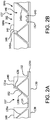
- FIG. 4A and 4B are side views of a leaflet frame 230 of a valve 200 wherein the leaflet frame 230 has been longitudinally cut and laid open to better illustrate the elements of the generally tubular-shaped leaflet frame 230, in accordance with an embodiment.
- the leaflet frame comprises a plurality of interconnected parabolic leaflet frame elements 235 terminating at commissure posts 236 defining leaflet windows 237.
- Each parabolic leaflet frame elements 235 may be defined by a leaflet window first side 233a and leaflet window second side 233b on either side of a plane P symmetrically bisecting the parabolic leaflet frame elements 235 aligned with the axial axis X, shown in FIG. 3B .
- the commissure posts 236 extend from an apex of intersecting parabolic leaflet frame elements 235.
- the length of the commissure post 236 may define the length of the coaptation region 146 between adjacent leaflet free edges 142. Where the commissure post 236 is made longer and the leaflet is attached thereto, a larger or wider coaptation region 146 may be defined between adjacent leaflet free edges 142.
- each leaflet 240 has substantially the shape of a parabola having a leaflet first side 241 a including a leaflet first side region 284a and a leaflet second side 241b including a leaflet second side region 284b defined by a plane P symmetrically aligned with the axial axis X bisecting the parabola, and a leaflet free edge 142 between the leaflet first side 241a and a leaflet second side 241b.
- the strain relief frame covering 252 provides a transition region that provides strain relief between the leaflet frame 130 and the leaflet 240.
- a leaflet 240 is shown located within the leaflet window 237 and the leaflet reinforcing member 249 being within the leaflet first side region 284a.
- the film 160 is generally any sheet-like material that is biologically compatible and configured to couple to the leaflet frame 130, in accordance with embodiments. It is understood that the term “film” is used generically for one or more biocompatible materials suitable for a particular purpose.
- the leaflets 140 are also comprised of the film 160.
- the biocompatible material is a film 160 that is not of a biological source and that is sufficiently flexible and strong for the particular purpose, such as a biocompatible polymer.
- the film 160 comprises a biocompatible polymer that is combined with an elastomer, referred to as a composite.
- the film 160 may be formed from a generally tubular material to at least partially cover the leaflet frame 130.
- the film 160 can comprise one or more of a membrane, composite material, or laminate. Details of various types of film 160 are discussed below.
- the film 160 comprises a biocompatible polymer that is combined with an elastomer, referred to as a composite material.
- a material includes a composite material comprising an expanded fluoropolymer membrane, which comprises a plurality of spaces within a matrix of fibrils, and an elastomeric material. It should be appreciated that multiple types of fluoropolymer membranes and multiple types of elastomeric materials can be combined to form a laminate while remaining within the scope of the present disclosure. It should also be appreciated that the elastomeric material can include multiple elastomers, multiple types of non-elastomeric components, such as inorganic fillers, therapeutic agents, radiopaque markers, and the like while remaining within the scope of the present disclosure.
- the composite material includes an expanded fluoropolymer material made from porous ePTFE membrane, for instance as generally described in U.S. Patent No. 7,306,729 to Bacino .
- the expandable fluoropolymer used to form the expanded fluoropolymer material described, may comprise PTFE homopolymer. In alternative embodiments, blends of PTFE, expandable modified PTFE and/or expanded copolymers of PTFE may be used.
- suitable fluoropolymer materials are described in, for example, U.S. Patent No. 5,708,044, to Branca , U.S. Patent No. 6,541,589, to Baillie , U.S. Patent No. 7,531,611, to Sabol et al. , U.S. Patent Application No. 11/906,877, to Ford , and U.S. Patent Application No. 12/410,050, to Xu et al.
- the expanded fluoropolymer membrane can comprise any suitable microstructure for achieving the desired leaflet performance.
- the expanded fluoropolymer comprises a microstructure of nodes interconnected by fibrils, such as described in U.S. Patent No. 3,953,566 to Gore .
- the fibrils radially extend from the nodes in a plurality of directions, and the membrane has a generally homogeneous structure.
- Membranes having this microstructure may typically exhibit a ratio of matrix tensile strength in two orthogonal directions of less than or equal to 2, and possibly less than 1.5.
- the expanded fluoropolymer membrane has a microstructure of substantially only fibrils, as is generally taught by U.S. Patent No. 7,306,729, to Bacino .
- the expanded fluoropolymer membrane having substantially only fibrils can possess a high surface area, such as greater than 20m 2 /g, or greater than 25m 2 /g, and in some embodiments can provide a highly balanced strength material having a product of matrix tensile strengths in two orthogonal directions of at least 1.5 x 10 5 MPa 2 , and/or a ratio of matrix tensile strengths in two orthogonal directions of less than 4, and possibly less than 1.5.
- the expanded fluoropolymer membrane can be tailored to have any suitable thickness and mass to achieve the desired leaflet performance.
- the leaflet 140 comprises an expanded fluoropolymer membrane having a thickness of about 0.1 ⁇ m.
- the expanded fluoropolymer membrane can possess a mass per area of about 1.15 g/m 2 .
- Membranes according to an embodiment of the invention can have matrix tensile strengths of about 411 MPa in the longitudinal direction and 315 MPa in the transverse direction.
- Composite materials described herein can be tailored to have any suitable thickness and mass to achieve the desired leaflet performance.
- Composite materials according to embodiments can include fluoropolymer membranes and have a thickness of about 1.9 ⁇ m and a mass per area of about 4.1 g/m 2 . In other embodiments, the fluoropolymer membranes have a thickness of about 100 ⁇ m and a mass per area of about 100 g/ m 2 .
- the expanded fluoropolymer membrane combined with elastomer to form a composite material provides the elements of the present disclosure with the performance attributes required for use in high-cycle flexural implant applications, such as heart valve leaflets, in various ways.
- the addition of the elastomer can improve the fatigue performance of the leaflet by eliminating or reducing the stiffening observed with ePTFE-only materials.
- the elastomer occupies substantially all of the pore volume or space within the porous structure of the expanded fluoropolymer membrane.
- the elastomer is present in a portion of the pores of the at least one fluoropolymer layer. Having elastomer filling the pore volume or present in a portion of the pores reduces the space in which foreign materials can be undesirably incorporated into the composite material.
- An example of such foreign material is calcium that may be drawn into the membrane from contact with the blood. If calcium becomes incorporated into the composite material, as used in a heart valve leaflet, for example, mechanical damage can occur during cycling open and closed, thus leading to the formation of holes in the leaflet and degradation in hemodynamics.
- the elastomer that is combined with the ePTFE is a thermoplastic copolymer of tetrafluoroethylene (TFE) and perfluoromethyl vinyl ether (PMVE), such as described in U.S. Patent No. 7,462,675 to Chang et al.
- TFE tetrafluoroethylene
- PMVE perfluoromethyl vinyl ether
- the elastomer is combined with the expanded fluoropolymer membrane such that the elastomer occupies substantially all of the void space or pores within the expanded fluoropolymer membrane to form a composite material. This filling of the pores of the expanded fluoropolymer membrane with elastomer can be performed by a variety of methods.
- a method of filling the pores of the expanded fluoropolymer membrane includes the steps of dissolving the elastomer in a solvent suitable to create a solution with a viscosity and surface tension that is appropriate to partially or fully flow into the pores of the expanded fluoropolymer membrane and allow the solvent to evaporate, leaving the filler behind.
- the composite material comprises three layers: two outer layers of ePTFE and an inner layer of a fluoroelastomer disposed therebetween. Additional fluoroelastomers can be suitable and are described in U.S. Publication No. 2004/0024448 to Chang et al.
- a method of filling the pores of the expanded fluoropolymer membrane includes the steps of delivering the filler via a dispersion to partially or fully fill the pores of the expanded fluoropolymer membrane.
- a method of filling the pores of the expanded fluoropolymer membrane includes the steps of bringing the porous expanded fluoropolymer membrane into contact with a sheet of the elastomer under conditions of heat and/or pressure that allow elastomer to flow into the pores of the expanded fluoropolymer membrane.
- a method of filling the pores of the expanded fluoropolymer membrane includes the steps of polymerizing the elastomer within the pores of the expanded fluoropolymer membrane by first filling the pores with a prepolymer of the elastomer and then at least partially curing the elastomer.
- the leaflets constructed from fluoropolymer materials or ePTFE generally performed better with increasing percentages of elastomer resulting in significantly increased cycle lives.
- the elastomer combined with the ePTFE is a thermoplastic copolymer of tetrafluoroethylene and perfluoromethyl vinyl ether, such as described in U.S. Patent No. 7,462,675 to Chang et al. , and other references that would be known to those of skill in the art.
- biocompatible polymers which can be suitable for use in leaflet 140 include but are not limited to the groups of urethanes, silicones(organopolysiloxanes), copolymers of silicon-urethane, styrene/isobutylene copolymers, polyisobutylene, polyethylene-co-poly(vinyl acetate), polyester copolymers, nylon copolymers, fluorinated hydrocarbon polymers and copolymers or mixtures of each of the foregoing.
- Each leaflet window 137 is provided with a biocompatible material, such as a film 160, which is coupled to a portion of the leaflet window sides 133 with the film 160 defining a leaflet 140, as shown in FIG. 1A-1D and 2B .
- a biocompatible material such as a film 160
- Each leaflet 140 defines a leaflet free edge 142 and a leaflet base 143, in accordance with an embodiment. As will be described below, it is anticipated that a plurality of embodiments of leaflet shapes, including with and without a defined leaflet base 143, may be provided.
- the film 160 is coupled to at least a portion of the leaflet window first side 133a and leaflet window second side 133b and to the leaflet window base 134 where the leaflet 140 is defined by the portion of the leaflet window first side 133a, the leaflet window second side 133b and to the leaflet window base 134.
- the leaflet 140 has a leaflet upstream side 193 and a leaflet downstream side 191 opposite the leaflet upstream side 193.
- the leaflet upstream side 193 is that side of the leaflet 140 that is facing away from the leaflet frame 130 when in the open position and the leaflet downstream side 191 is that side of the leaflet 140 that is facing toward the leaflet frame 130 when in the open position.
- the valve 100 When the leaflets 140 are in a fully open position, the valve 100 presents a substantially circular valve orifice 102 as shown in FIG. 1C . Fluid flow is permitted through the valve orifice 102 when the leaflets 140 are in the open position. Since the leaflet first side region 184a is stiffer than the leaflet second side region 184b, the leaflet first side region 184a does not open fully leaving a pocket 194 defined in part by the leaflet downstream side 191 adjacent the leaflet first side region 184a. As the blood exits the valve 100, retrograde flow may enter the pocket 194 so as to wash out the area defined by the leaflet downstream side 191.
- a geometric orifice area is an area measurement of an axial projection of an open area defined by the valve when in the fully open position.
- a first portion of a leaflet will extend further into the valve orifice defined by the valve frame, that is, not open as much, than a second portion of the same leaflet, which opens further. From an axial viewpoint, the first portion of the leaflet will create a smaller GOA than the second portion of the leaflet
- FIG. 1C is an axial view of the valve 100 in the fully open position.
- the leaflets 140 do not completely open to conform to the leaflet frame inner surface 126b, therefore projecting a smaller geometric orifice area compared with an orifice area of a frame without leaflets.
- the leaflet frame inner surface 126b in cross-section transverse to the X axis defines a frame orifice 139 having a frame orifice area that is circular in shape.
- the axial view shown in FIG. 1C is bisected into six segments by three planes P1, P2, P3 where each plane passes through one commissure post 136, the axis X and bisects a leaflet 140 in half, defining a first segment 172 and a second segment 174.
- the leaflet first side region 184a of the leaflet 140 in the first segment 172 extends more into the frame orifice 139 defined by the leaflet frame inner surface 126b defining a smaller GOA, for example, up to 70 percent smaller, than the leaflet second side region 184b in the second segment 174.
- FIG. 1D is an axial view of the valve 100 in the partially open position or a partially closed position.
- the leaflet first side region 184a of one leaflet 140 is adjacent to the leaflet second side region 184b of an adjacent leaflet 140.
- the leaflet first side region 184a is stiffer compared to the leaflet second side region 184b.
- the leaflet second side region 184b will initially open first and will close last compared to the leaflet first side region 184a. This controlled motion provides a consistent leaflet motion from cycle to cycle imparting the benefits previously described.
- the leaflets 140 As the leaflets 140 cycle between the open and closed positions, the leaflets 140 generally flex about the leaflet base 143 and the portion of the leaflet window first side 133a and the leaflet window second side 133b to which the leaflets 140 are coupled. Since the leaflet first side region 184a is more stiff than the leaflet second side region 184b, the leaflet first side 141a does not flex as much about the leaflet window first side 133a as compared with the leaflet second side 141b defining a channel 145 between the leaflet first side 141a of one leaflet 140 and the leaflet second side 141b of an adjacent leaflet 140 when the leaflet is not in the closed position. The channel 145 is defined when the leaflet 140 moves from the closed position.
- the channel 145 allows for blood flow therethrough throughout the opening phase of the leaflet 140 and thus reduces the potential for blood pooling, stagnation and clot formation between the leaflet first side141a and the leaflet window first side 133a, and the leaflet second side 141b and the leaflet window second side 133b, and therebetween.
- each leaflet free edge 142 abuts an adjacent half of a leaflet free edge 142 of an adjacent leaflet 140, as shown in FIG. 1E .
- the three leaflets 140 of the embodiment of FIG. 1E meet at a triple point 148.
- the valve orifice 102 is occluded when the leaflets 140 are in the closed position stopping fluid flow.
- the leaflet first side region 184a is stiffer than the leaflet central region 182 and the leaflet second side region 184b, the flexibility of the leaflet central region 182 and the leaflet second side region 184b of an adjacent leaflet 140 allows for coaptation with the leaflet first side region 184a allowing for proper closing of the valve 100.
- each leaflet 140 includes a leaflet central region 182, a leaflet first side region 184a, and a leaflet second side region 184b on opposite sides of the leaflet central region 182.
- the leaflet central region 182 is defined by a shape substantially that of a rectangle defined by two leaflet central region sides 183, the leaflet base 143 and the leaflet free edge 142.
- the two leaflet central region sides 183 extend from the leaflet base 143 to the leaflet free edge 142.
- the leaflet first side region 184a is stiffer than the leaflet central region 182 and the leaflet second side region 184b.
- the stiffness characteristics of the leaflet first side region 184a, leaflet second side region 184b and the leaflet central region 182 may be affected by any suitable means.
- the leaflet 140 comprises a film that is a laminate of multiple layers of composite material. Additional layers of composite material are provided in the leaflet first side region 184a which imparts additional stiffness to the leaflet first side region 184a as compared with the leaflet central region 182 and the leaflet second side region 184b.
- Example 1 provides additional details as to the embodiment just described.
- the parabolic shaped leaflet window 237 does not define a distinct base but only a leaflet window first side 233a and leaflet window second side 233b on either side of a plane P symmetrically bisecting the parabolic leaflet frame elements 235 aligned with the axial axis X, shown in FIGs. 4A and 4B .
- the film 160 is coupled to at least a portion of the leaflet window first side 233a and leaflet window second side 233b where the leaflet 240 is defined by the portion of the leaflet window first side 233a and the leaflet window second side 133b.
- the leaflet 240 has a leaflet upstream side 193 and a leaflet downstream side 191 opposite the leaflet upstream side 193.
- the leaflet upstream side 193 is that side of the leaflet 140 that is facing away from the leaflet frame 230 when in the open position and the leaflet downstream side 191 is that side of the leaflet 240 that is facing toward the leaflet frame 130 when in the open position.
- FIGs. 1A-E and 3 , 4A and 4B are examples of two different leaflet and leaflet window geometries that are suitable for the particular purpose. It is understood that other leaflet and leaflet window geometries may also be suitable for the particular purpose and are not limited thereto.
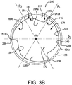
- the axial view of the valve 200 shown in FIG. 3B is bisected into six segments by three planes P1, P2, P3 where each plane passes through one commissure post 236, the axis X and bisects a leaflet 240 in half, defining a first segment 172 and a second segment 174.
- the portion of the leaflet in the first segment 172 defines a smaller GOA than the portion of the leaflet in the second segment 174, by virtue of the leaflet first side region 284a extending further into the frame orifice 139 defined by the leaflet frame inner surface 126b.
- FIG. 3B is an axial view of the valve 200 in the partially open position or a partially closed position.
- the leaflet first side region 284a of one leaflet 240 is adjacent to the leaflet second side region 284b of an adjacent leaflet 240.
- the leaflet first side region 284a is stiffer compared to the leaflet second side region 284b.
- the leaflet second side region 284b will initially open first and will close last compared to the leaflet first side region 284a. This controlled motion provides a consistent leaflet motion from cycle to cycle imparting the benefits previously described.
- the leaflet 140 can be configured to actuate at a pressure differential in the blood caused, for example, by the contraction of a ventricle or atrium of the heart, such pressure differential typically resulting from a fluid pressure building up on one side of the valve 100 when closed.
- a pressure differential in the blood caused, for example, by the contraction of a ventricle or atrium of the heart, such pressure differential typically resulting from a fluid pressure building up on one side of the valve 100 when closed.
- the leaflet 140 opens and blood flows therethrough.
- the pressure equalizes.
- the leaflet 140 returns to the closed position generally preventing the retrograde flow of blood through the inflow side of the valve 100.
- leaflet frame 130 may comprise any number of leaflet windows 137, and thus leaflets 140, suitable for a particular purpose, in accordance with embodiments.
- Leaflet frames 130 comprising one, two, three or more leaflet windows 137 and corresponding leaflets 140 are anticipated.
- leaflets may not necessarily be supported by a frame.
- the leaflets may be supported by the inner wall within a solid-walled conduit without a frame that defines leaflet windows and commissure posts.
- the leaflets may be constructed as in the tissue valve art that are formed into the desired shape without a frame.
- each leaflet in another embodiment of a valve including a plurality of leaflets, each leaflet includes a leaflet first side and a leaflet second side opposite from the leaflet first side. Each leaflet first side is coupled with the leaflet second side of an adjacent leaflet at a commissure.
- the plurality of leaflets defines an orifice, also referred to as a lumen, when the leaflets are in an open position. Each of the leaflet first sides extend further into the orifice than each of the leaflet second sides.
- a prosthetic valve comprises a plurality of leaflets.
- Each leaflet includes a leaflet first side region and a leaflet second side region opposite from the leaflet first side region.
- Each leaflet defines a leaflet base and a leaflet free edge opposite from the leaflet base.
- Each leaflet first side region is coupled with the leaflet second side region of an adjacent leaflet at a commissure.
- the leaflet base of the plurality of leaflets defines an orifice.
- the leaflet second side regions extend further into the orifice than the leaflet first side region when the leaflets are in the fully open position.
- a prosthetic valve comprises a plurality of leaflets.
- Each leaflet includes a leaflet first side region and a leaflet second side region opposite from the leaflet first side region.
- the leaflet first side region has a first bending stiffness and the leaflet second side region has a second bending stiffness.
- the first bending stiffness is greater than the second bending stiffness.
- each leaflet opens asymmetrically.
- a prosthetic valve comprises a plurality of leaflets.
- Each leaflet includes a leaflet first side region and a leaflet second side region opposite from the leaflet first side region.
- the leaflet first side region being more resistant to moving compared with the leaflet second side region.
- each leaflet opens asymmetrically.
- a prosthetic valve comprises a plurality of leaflets.
- Each leaflet includes a leaflet first side region and a leaflet second side region opposite from the leaflet first side region.
- the leaflet first side region being slower to open compared with the leaflet second side region.
- each leaflet opens asymmetrically.
- a prosthetic valve comprises a plurality of leaflets.
- Each leaflet includes a leaflet first side region and a leaflet second side region opposite from the leaflet first side region.
- Each leaflet defines a leaflet base and a leaflet free edge opposite from the leaflet base.
- Each leaflet first side region is coupled with the leaflet second side region of an adjacent leaflet at a commissure.
- the leaflet base of the plurality of leaflets defines an orifice. At least one of the leaflet second side regions extends further into the orifice than the leaflet first side region when the leaflets are in the fully open position.
- a prosthetic valve comprises a plurality of leaflets. At least one leaflet includes a leaflet first side region and a leaflet second side region opposite from the leaflet first side region.
- the leaflet first side region has a first thickness and the leaflet second side region has a second thickness. The first thickness is greater than the second thickness.
- a prosthetic valve comprises a plurality of leaflets.
- Each leaflet includes a leaflet first side region and a leaflet second side region opposite from the leaflet first side region. At least one of the leaflets has a leaflet first side region having a first bending stiffness and the leaflet second side region having a second bending stiffness, wherein the first bending stiffness is greater than the second bending stiffness.
- a prosthetic valve comprises a plurality of leaflets.
- Each leaflet includes a leaflet first side region and a leaflet second side region opposite from the leaflet first side region. At least one of the leaflets presents with the leaflet first side region being more resistant to moving compared with the leaflet second side region.
- a prosthetic valve comprises a plurality of leaflets.
- Each leaflet includes a leaflet first side region and a leaflet second side region opposite from the leaflet first side region. At least one of the leaflets presenting the leaflet first side region being slower to open compared with the leaflet second side region.
- a prosthetic valve comprises a plurality of leaflets.
- Each leaflet includes a leaflet first side region and a leaflet second side region opposite from the leaflet first side region. At least one leaflet has a thickness that tapers from the leaflet first side region to the leaflet second side region.
- a prosthetic valve comprises a plurality of leaflets.
- Each leaflet includes a leaflet first side region and a leaflet second side region opposite from the leaflet first side region. At least one leaflet has a thickness that varies from the leaflet first side region to the leaflet second side region.
- leaflet embodiments provided herein may be applied to any prosthetic valve design regardless as to how the leaflets are supported to function as described.
- the valve 100 can be configured to prevent interference with a heart conduction system by not covering a bundle branch in the left ventricle when implanted, such as might be encountered with an aortic valve replacement procedure.
- the valve 100 can comprise a length of less than about 25 mm or less than about 18 mm.
- the valve 100 can also comprise an aspect ratio of less than one, wherein the ratio describes the relationship between the length of the valve 100 to the expanded, functional diameter.
- the valve 100 can be constructed at any length and, more generally, any desirable dimension.
- the valve 100 further comprises a sewing cuff about a leaflet frame 130 in accordance with an embodiment.
- the sewing cuff is operable to provide structure that receives suture for coupling to the implant site.
- the sewing cuff may comprise any suitable material, such as, but not limited to, double velour polyester.
- the sewing cuff may be located circumferentially around a perimeter of the base of the leaflet frame 130. Sewing cuffs are known in the art.
- the valve 100 can further comprise a bio-active agent.
- Bio-active agents can be coated onto a portion or the entirety of the film 160 for controlled release of the agents once the valve 100 is implanted.
- the bio-active agents can include, but are not limited to, vasodilator, anti-coagulants, anti-platelet, anti-thrombogenic agents such as, but not limited to, heparin.
- Other bio-active agents can also include, but are not limited to agents such as, for example, antiproliferative/antimitotic agents including natural products such as vinca alkaloids (i.e. vinblastine, vincristine, and vinorelbine), paclitaxel, epidipodophyllotoxins (i.e.
- antibiotics dactinomycin (actinomycin D) daunorubicin, doxorubicin and idarubicin
- anthracyclines mitoxantrone, bleomycins, plicamycin (mithramycin) and mitomycin
- enzymes L-asparaginase which systemically metabolizes L-asparagine and deprives cells which do not have the capacity to synthesize their own asparagine
- antiplatelet agents such as G(GP) IIb/IIIa inhibitors and vitronectin receptor antagonists
- anti-proliferative/antimitotic alkylating agents such as nitrogen mustards (mechlorethamine, cyclophosphamide and analogs, melphalan, chlorambucil), ethylenimines and methylmelamines (hexamethylmelamine and thiotepa), alkyl sulfonates-busulfan, nitros
- anti-coagulants heparin, synthetic heparin salts and other inhibitors of thrombin
- fibrinolytic agents such as tissue plasminogen activator, streptokinase and urokinase), aspirin, dipyridamole, ticlopidine, clopidogrel, abciximab
- antimigratory antisecretory (breveldin)
- anti-inflammatory such as adrenocortical steroids (cortisol, cortisone, fludrocortisone, prednisone, prednisolone, 6 ⁇ -methylprednisolone, triamcinolone, betamethasone, and dexamethasone), non-steroidal agents (salicylic acid derivatives i.e.
- Embodiments described herein also pertain to a method of making the valve 100 embodiments as described herein.
- a mandrel 710 that is cylindrical can be used.
- the mandrel 710 comprises a structural form operable to receive the leaflet frame 130 thereon.
- An embodiment of a method of making a valve 100 comprises the steps of wrapping a first film layer 160a, e.g., a composite as described herein, into a tubular form about the mandrel 710; placing the leaflet frame 130 over the first film layer 160a, as shown in FIG.
- a first film layer 160a e.g., a composite as described herein
- the resulting valve 100 comprises a leaflet 140 having a leaflet first side region 184a that includes a leaflet reinforcing member 149 that is the first film layer 160a coupled to the second film layer 160b, and the leaflet central region 182 and leaflet second side region that only includes the second film layer 160b.
- a small border of the first film layer 160a that depends from the leaflet window second side 133b and the leaflet window base 134 within the leaflet window 137 provides a strain relief that reduces the strain in the leaflet 140 at the interface between the leaflet 140 and the leaflet window 137 of the leaflet frame 130.
- a heart valve having polymeric leaflets formed from a composite material having an expanded fluoropolymer membrane and an elastomeric material and joined to a metallic frame, and further a having a strain relief frame covering and a leaflet reinforcing member was constructed according to the following process:
- a leaflet frame 130 was laser machined from a length of MP35N cobalt chromium tube hard tempered with an outside diameter of 23.0 mm and a wall thickness of 0.6 mm. The leaflet frame was electro-polished resulting in 0.01 mm material removal from each surface and leaving the edges rounded. The leaflet frame was cleaned by submersion in an ultrasonic bath of acetone for approximately five minutes.
- a strain relief was attached to the leaflet frame in the following manner.
- a steel metal mandrel having tapered diameter of 21.5 mm to 22.0 mm outer diameter (taper angle of 0.1 degrees) was obtained.
- a thin-walled (122 ⁇ m) sintered 15 mm diameter ePTFE tube was disposed on the metal mandrel by stretching radially over another tapered mandrel and transferring to the 21.5 mm to 22.0 mm mandrel.
- One layer of a substantially nonporous ePTFE membrane with an FEP coating was circumferentially wrapped on the mandrel with the FEP side towards the mandrel.
- This membrane was adhered by tacking using a soldering iron (Weller) set to 400°C, thereby creating a covered mandrel.
- the ePTFE and substantially nonporous ePTFE membrane combined to serve as an inner release liner. This entire release liner was removed in a later step.
- a composite material comprising a membrane of ePTFE imbibed with a fluoroelastomer was obtained.
- the composite material was comprised of three layers: two outer layers of ePTFE and an inner layer of a fluoroelastomer disposed therebetween.
- the ePTFE membrane was manufactured according to the general teachings described in U.S. Patent No. 7,306,729 .
- the fluoroelastomer was formulated according to the general teachings described in U.S. Patent No. 7,462,675 .
- the fluoroelastomer consists essentially of between about 65 and 70 weight percent perfluoromethyl vinyl ether and complementally about 35 and 30 weight percent tetrafluoroethylene.
- the percent weight of the fluoroelastomer relative to the ePTFE was about 53%.
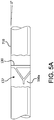
- the clean leaflet frame was then placed over the leaflet frame covering on the mandrel from the small diameter side of the taper until it fit snugly, with the base of the frame toward the small diameter portion of the taper, as shown in FIG. 5A .
- leaflet frame covering that extended beyond the base of the frame toward the small taper was then everted over the frame until the entire frame was encapsulated and the folded edge of the everted material was flush with the base of the frame to create an outer leaflet frame covering, as shown in FIG. 5B .
- a sacrificial longitudinally expanded PTFE film having a thickness of about 0.1mm were tightly wrapped around the covered frame.
- the resulting assembly was then placed in a convection oven set at 320°C for 20 minutes. This assembly was removed from the oven and allowed to cool, and the outer sacrificial layers were removed. This assembly was then removed from the mandrel, ensuring that it was released from the inner sacrificial layer.
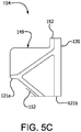
- the leaflet frame cover was trimmed, as shown in FIG. 2B , to create a construct 154 consisting of a leaflet frame 130, a leaflet reinforcing member 149 adjacent to one side of each post and a strain relief frame covering 152.
- the remainder of the frame covering was trimmed at 1mm from the edge of the frame, leaving 6 mm leaflet reinforcing member 149 on one side of each post, as shown in FIG. 5C , the leaflet window first side 133a, as shown in FIG. 2A .
- a leaflet material was then prepared having a membrane layer of ePTFE imbibed with a fluoroelastomer. More specifically, the membrane layer of ePTFE was manufactured according to the general teachings described in U.S. Patent No. 7,306,729 .
- the ePTFE membrane was tested in accordance with the methods described below.
- the ePTFE membrane had a mass per area of about 0.6 g/m 2 , a porosity of about 90%, a thickness of about 3 ⁇ m, a bubble point of about 450 KPa, a matrix tensile strength of about 350 MPa in the longitudinal direction and about 250 MPa in the transverse direction. This membrane was imbibed with the same fluoroelastomer as described above.
- the fluoroelastomer was dissolved in Novec HFE7500 (3M, St Paul, MN, USA) in an about 2.5% concentration.
- the solution was coated using a mayer bar onto the ePTFE membrane (while being supported by a polypropylene release film) and dried in a convection oven set to about 145°C for about 30 seconds. After two coating steps, the resulting composite material of ePTFE/fluoroelastomer had a mass per area of about 4 g/m 2 .
- the final leaflet was comprised of about 30% fluoropolymer by weight with a thickness of 25 ⁇ m. Each leaflet had 31 layers of the composite.
- the encapsulated frame with frame covering defining a strain relief and a reinforcing member was then attached to the leaflet material in a cylindrical or tubular shape in the following manner.
- the encapsulated frame with strain relief covering and reinforcing member was placed on the release liner-covered tapered mandrel described above, as shown in FIG. 5D .
- a sacrificial longitudinally expanded PTFE film having a thickness of about 0.1 mm were tightly wrapped around the covered frame.
- the resulting assembly was then placed in a convection oven set at 280°C for 60 minutes. This assembly was removed from the oven and allowed to cool, and the outer sacrificial layers were removed. This assembly was then removed from the mandrel, ensuring that it was released from the inner sacrificial layer.
- the leaflet material was trimmed approximately 5 mm above the leaflet frame first end 121 a, also referred to as the frame top.
- the resulting assembly was placed in a convection oven set at 150°C for 15 min while closing the valve with 5 cm of Hg vacuum to close the leaflets.
- the assembly was removed from the oven and allowed to cool.
- Leaflets were trimmed using scissors to a height of approximately 1-2 mm above the coaptation line.
- the average maximum leaflet thickness in the leaflet first side region was 281 micrometers and the average maximum leaflet thickness in the leaflet second side region was 27 micrometers. These measurements were an average of three measurements obtained on a Mitutoyo Litematic VL-50A (Aurora, IL) digimatic measuring unit.
- a geometric orifice area (GOA) test was performed. With a flow of 450 ml/s of 37°C saline flowing through the 22mm ID valve, a picture was taken of the leaflets in the fully open position. This image was analyzed by pasting the image in CAD software (SOLIDWORKS 2012). A circle was drawn connecting the inner surface of the centers of each of the three posts. From the middle of each of these three posts, a diameter line was drawn. These diameter lines split the image into six (6) slices, or two slices per leaflet, similar to FIG. 1C . A spline line 156 was then drawn around the full circumference of the edge of the open leaflets.
- the geometric orifice area (GOA) for each of the three leaflets was then calculated by calculating the luminal area within the spline for the 1/3 of the total valve area encompassed by each leaflet. This resulted in a calculation of GOA for each leaflet (the sum of these three GOAs equals the GOA of the entire valve). Subsequently, the GOA of each side of the leaflet was calculated by using the diameter line drawn previously which bisects the leaflet. The GOA from the reinforced section of the leaflet is always less than the GOA of the unreinforced section. For the example presented above, the ratio of the GOA on the reinforced side of the leaflet to the total leaflet GOA was 34%, 37%, and 33%, while the other side of the leaflet had a ratio of 66%, 63%, and 67%, respectively.
- valve assembly was placed within a silicone annular ring (support structure), supporting its outer diameter without changing its diameter, to allow the valve assembly to be subsequently evaluated in a real-time pulse duplicator.
- the process was performed according to the recommendations of the pulse duplicator manufacturer (ViVitro Laboratories Inc., Victoria BC, Canada).
- the valve assembly was then placed into a real-time left heart flow pulse duplicator system.
- the flow pulse duplicator system included the following components supplied by ViVitro Laboratories Inc., Victoria BC, Canada: a Super Pump, Servo Power Amplifier Part Number SPA 3891; a Super Pump Head, Part Number SPH 5891B, 38 cm 2 cylinder area; a valve station/fixture; Vivitro software capable of waveform control and data collection ; I/O module Part Number XXXX, TriPack Part Number TP 2001; a Sensor Interface, Part Number VB 2004; a Sensor Amplifier Component, Part Number AM 9991; and a Square Wave Electro Magnetic Flow Meter (positioned approximately 2 cm upstream of the valve), Carolina Medical Electronics Inc., East Bend, NC, USA.
- the outflow chamber used to evaluate the performance of the pulmonary valve was chosen such that the internal diameter of the outflow chamber was matched to that of the valve diameter.
- a 40ml source compliance, a large peripheral compliance was added to the tester to simulate physiological pulmonary conditions. Additionally, as a straight outflow chamber was used, the root compliance was not used in the test set-up.
- the flow pulse duplicator system uses a fixed displacement, piston pump to produce a desired fluid flow through the valve under test.
- Testing and definitions are consistent with ISO 5840-3, 2013 except where otherwise noted for testing to pulmonary conditions. While this testing is conducted to pulmonary conditions, testing and use (e.g. aortic, mitral, tricuspid, venous, etc) in other conditions is not excluded.
- the heart flow pulse duplicator system was adjusted to produce the desired flow (5.0 ⁇ 0.5 L/min), mean pressure (20 ⁇ 2 mmHg), simulated pulse rate (70 bpm), a 35% systolic duration sinusoidal waveform, and a stroke volume (i.e., the amount of fluid pushed by the driving pump) of 84 ⁇ 1 ml.
- the operating temperature was 37 ⁇ 1°C using 0.9% saline as test solution.
- the valve under test was then cycled for between 5 to 15 minutes.
- EOA effective orifice area
- ⁇ P mean differential pressure during the positive pressure interval of the systolic period
- regurgitant fraction is the amount of fluid or blood regurgitated through the valve divided by the Forward Volume (i.e., amount of flow passing through the valve during the forward phase of the valve).
- saline heated to 37°C was pumped at a steady rate though the valve to open it.
- Saline was pumped using a pump (WEG Electric, Duluth, GA, part number 10086261) with voltage regulator (Staco Energy Products, Miamisburg, OH, part number 3PN2210B) though the valve at 5 L/min (as measured by a large graduated cylinder and stopwatch).
- the valve was placed within a silicone holder in the recirculating loop that started and finished within an open 37 ⁇ 1 °C heated reservoir.
- An image of the valve was taken using a digital camera (Vision Research, Wayne, NJ, Model Miro EX4), and the GOA measured using the same technique as noted previously.
- the geometric open area on one half of each leaflet was 39% of each leaflets total GOA (i.e. other half of leaflet geometric open area was 61% of each leaflets total GOA).
- the surface area per unit mass was measured using the Brunauer-Emmett-Teller (BET) method on a Coulter SA3100Gas Adsorption Analyzer, Beckman Coulter Inc. Fullerton CA, USA.
- BET Brunauer-Emmett-Teller
- a sample was cut from the center of the expanded fluoropolymer membrane and placed into a small sample tube.
- the mass of the sample was approximately 0.1 to 0.2 g.
- the tube was placed into the Coulter SA-Prep Surface Area Outgasser (Model SA-Prep, P/n 5102014) from Beckman Coulter, Fullerton CA, USA and purged at about 110°C for about two hours with helium.
- sample tube was then removed from the SA-Prep Outgasser and weighed.
- sample tube was then placed into the SA3100 Gas adsorption Analyzer and the BET surface area analysis was run in accordance with the instrument instructions using helium to calculate the free space and nitrogen as the adsorbate gas.
- Bubble point and mean flow pore size were measured according to the general teachings of ASTM F31 6-03 using a capillary flow Porometer, Model CFP 1500AEXL from Porous Materials, Inc., Ithaca NY, USA.
- the sample membrane was placed into the sample chamber and wet with SilWick Silicone Fluid (available from Porous Materials Inc.) having a surface tension of about 20.1 dynes/cm.
- the bottom clamp of the sample chamber had an about 2.54 cm diameter hole. Isopropyl alcohol was used as the test fluid.
- Capwin software version 7.73.012 the following parameters were set as specified in the table below.
- mean flow pore size and pore size are used interchangeably.
- Membrane thickness was measured by placing the membrane between the two plates of a Kafer FZ1000/30 thickness snap gauge Kafer Messuhrenfabrik GmbH, Villingen-Schwenningen, Germany. The average of the three measurements was reported.
- the presence of elastomer within the pores can be determined by several methods known to those having ordinary skill in the art, such as surface and/or cross section visual, or other analyses. These analyses can be performed prior to and after the removal of elastomer from the leaflet.
- Tensile break load was measured using an INSTRON 122 tensile test machine equipped with flat-faced grips and a 0.445 kN load cell. The gauge length was about 5.08 cm and the cross-head speed was about 50.8 cm/min. The sample dimensions were about 2.54 cm by about 15.24 cm. For longitudinal measurements, the longer dimension of the sample was oriented in the highest strength direction. For the orthogonal MTS measurements, the larger dimension of the sample was oriented perpendicular to the highest strength direction. Each sample was weighed using a Mettler Toledo Scale Model AG204, then the thickness measured using the Kafer FZ1000/30 snap gauge. The samples were then tested individually on the tensile tester. Three different sections of each sample were measured.
- MTS (maximum load/cross-section area)*(bulk density of PTFE)/ (density of the porous membrane), wherein the bulk density of the PTFE was taken to be about 2.2 g/cm 3 .
- Bending stiffness was measured by following the general procedures set forth in ASTM D790. Unless large test specimens are available, the test specimen must be scaled down. The test conditions were as follows. The leaflet specimens were measured on a three-point bending test apparatus employing sharp posts placed horizontally about 5.08 mm from one another.
Landscapes
- Health & Medical Sciences (AREA)
- Engineering & Computer Science (AREA)
- Biomedical Technology (AREA)
- Cardiology (AREA)
- Oral & Maxillofacial Surgery (AREA)
- Transplantation (AREA)
- Heart & Thoracic Surgery (AREA)
- Vascular Medicine (AREA)
- Life Sciences & Earth Sciences (AREA)
- Animal Behavior & Ethology (AREA)
- General Health & Medical Sciences (AREA)
- Public Health (AREA)
- Veterinary Medicine (AREA)
- Manufacturing & Machinery (AREA)
- Prostheses (AREA)
Priority Applications (1)
| Application Number | Priority Date | Filing Date | Title |
|---|---|---|---|
| EP19202204.4A EP3613384A1 (en) | 2013-12-06 | 2014-12-05 | Asymmetric opening and closing prosthetic valve leaflet |
Applications Claiming Priority (4)
| Application Number | Priority Date | Filing Date | Title |
|---|---|---|---|
| US201361913235P | 2013-12-06 | 2013-12-06 | |
| US201461974653P | 2014-04-03 | 2014-04-03 | |
| US14/561,148 US9504565B2 (en) | 2013-12-06 | 2014-12-04 | Asymmetric opening and closing prosthetic valve leaflet |
| PCT/US2014/068727 WO2015085138A1 (en) | 2013-12-06 | 2014-12-05 | Asymmetric opening and closing prosthetic valve leaflet |
Related Child Applications (1)
| Application Number | Title | Priority Date | Filing Date |
|---|---|---|---|
| EP19202204.4A Division EP3613384A1 (en) | 2013-12-06 | 2014-12-05 | Asymmetric opening and closing prosthetic valve leaflet |
Publications (2)
| Publication Number | Publication Date |
|---|---|
| EP3076900A1 EP3076900A1 (en) | 2016-10-12 |
| EP3076900B1 true EP3076900B1 (en) | 2019-11-06 |
Family
ID=53269999
Family Applications (2)
| Application Number | Title | Priority Date | Filing Date |
|---|---|---|---|
| EP14821950.4A Active EP3076900B1 (en) | 2013-12-06 | 2014-12-05 | Asymmetric opening and closing prosthetic valve leaflet |
| EP19202204.4A Pending EP3613384A1 (en) | 2013-12-06 | 2014-12-05 | Asymmetric opening and closing prosthetic valve leaflet |
Family Applications After (1)
| Application Number | Title | Priority Date | Filing Date |
|---|---|---|---|
| EP19202204.4A Pending EP3613384A1 (en) | 2013-12-06 | 2014-12-05 | Asymmetric opening and closing prosthetic valve leaflet |
Country Status (8)
| Country | Link |
|---|---|
| US (4) | US9504565B2 (enExample) |
| EP (2) | EP3076900B1 (enExample) |
| JP (2) | JP6599330B2 (enExample) |
| CN (2) | CN105960220B (enExample) |
| AU (3) | AU2014360294B2 (enExample) |
| CA (2) | CA3065734A1 (enExample) |
| ES (1) | ES2771484T3 (enExample) |
| WO (1) | WO2015085138A1 (enExample) |
Cited By (15)
| Publication number | Priority date | Publication date | Assignee | Title |
|---|---|---|---|---|
| US10856984B2 (en) | 2017-08-25 | 2020-12-08 | Neovasc Tiara Inc. | Sequentially deployed transcatheter mitral valve prosthesis |
| US10940001B2 (en) | 2012-05-30 | 2021-03-09 | Neovasc Tiara Inc. | Methods and apparatus for loading a prosthesis onto a delivery system |
| US11311376B2 (en) | 2019-06-20 | 2022-04-26 | Neovase Tiara Inc. | Low profile prosthetic mitral valve |
| US11357622B2 (en) | 2016-01-29 | 2022-06-14 | Neovase Tiara Inc. | Prosthetic valve for avoiding obstruction of outflow |
| US11389291B2 (en) | 2013-04-04 | 2022-07-19 | Neovase Tiara Inc. | Methods and apparatus for delivering a prosthetic valve to a beating heart |
| US11413139B2 (en) | 2011-11-23 | 2022-08-16 | Neovasc Tiara Inc. | Sequentially deployed transcatheter mitral valve prosthesis |
| US11419720B2 (en) | 2010-05-05 | 2022-08-23 | Neovasc Tiara Inc. | Transcatheter mitral valve prosthesis |
| US11464631B2 (en) | 2016-11-21 | 2022-10-11 | Neovasc Tiara Inc. | Methods and systems for rapid retraction of a transcatheter heart valve delivery system |
| US11491006B2 (en) | 2019-04-10 | 2022-11-08 | Neovasc Tiara Inc. | Prosthetic valve with natural blood flow |
| US11497602B2 (en) | 2012-02-14 | 2022-11-15 | Neovasc Tiara Inc. | Methods and apparatus for engaging a valve prosthesis with tissue |
| US11602429B2 (en) | 2019-04-01 | 2023-03-14 | Neovasc Tiara Inc. | Controllably deployable prosthetic valve |
| US11737872B2 (en) | 2018-11-08 | 2023-08-29 | Neovasc Tiara Inc. | Ventricular deployment of a transcatheter mitral valve prosthesis |
| US11779742B2 (en) | 2019-05-20 | 2023-10-10 | Neovasc Tiara Inc. | Introducer with hemostasis mechanism |
| US11998447B2 (en) | 2019-03-08 | 2024-06-04 | Neovasc Tiara Inc. | Retrievable prosthesis delivery system |
| US12109111B2 (en) | 2015-12-15 | 2024-10-08 | Neovasc Tiara Inc. | Transseptal delivery system |
Families Citing this family (54)
| Publication number | Priority date | Publication date | Assignee | Title |
|---|---|---|---|---|
| US9744033B2 (en) | 2011-04-01 | 2017-08-29 | W.L. Gore & Associates, Inc. | Elastomeric leaflet for prosthetic heart valves |
| US9554806B2 (en) | 2011-09-16 | 2017-01-31 | W. L. Gore & Associates, Inc. | Occlusive devices |
| US9283072B2 (en) | 2012-07-25 | 2016-03-15 | W. L. Gore & Associates, Inc. | Everting transcatheter valve and methods |
| US10376360B2 (en) | 2012-07-27 | 2019-08-13 | W. L. Gore & Associates, Inc. | Multi-frame prosthetic valve apparatus and methods |
| US9144492B2 (en) | 2012-12-19 | 2015-09-29 | W. L. Gore & Associates, Inc. | Truncated leaflet for prosthetic heart valves, preformed valve |
| US9968443B2 (en) | 2012-12-19 | 2018-05-15 | W. L. Gore & Associates, Inc. | Vertical coaptation zone in a planar portion of prosthetic heart valve leaflet |
| US10039638B2 (en) | 2012-12-19 | 2018-08-07 | W. L. Gore & Associates, Inc. | Geometric prosthetic heart valves |
| US10966820B2 (en) | 2012-12-19 | 2021-04-06 | W. L. Gore & Associates, Inc. | Geometric control of bending character in prosthetic heart valve leaflets |
| US9737398B2 (en) | 2012-12-19 | 2017-08-22 | W. L. Gore & Associates, Inc. | Prosthetic valves, frames and leaflets and methods thereof |
| US10321986B2 (en) | 2012-12-19 | 2019-06-18 | W. L. Gore & Associates, Inc. | Multi-frame prosthetic heart valve |
| US9101469B2 (en) | 2012-12-19 | 2015-08-11 | W. L. Gore & Associates, Inc. | Prosthetic heart valve with leaflet shelving |
| US11911258B2 (en) | 2013-06-26 | 2024-02-27 | W. L. Gore & Associates, Inc. | Space filling devices |
| US9504565B2 (en) | 2013-12-06 | 2016-11-29 | W. L. Gore & Associates, Inc. | Asymmetric opening and closing prosthetic valve leaflet |
| EP3182929B1 (en) | 2014-08-18 | 2023-08-09 | Edwards Lifesciences Corporation | Frame with integral sewing cuff for prosthetic valves |
| US9827094B2 (en) | 2014-09-15 | 2017-11-28 | W. L. Gore & Associates, Inc. | Prosthetic heart valve with retention elements |
| HK1250897A1 (zh) | 2015-05-14 | 2019-01-18 | W. L. Gore & Associates, Inc. | 用於心耳的堵塞的装置 |
| WO2017197266A1 (en) * | 2016-05-13 | 2017-11-16 | Terumo Cardiovascular Systems Corporation | Temporary disposable scaffold stand and tools to facilitate reconstructive valve surgery |
| AU2018334191B2 (en) | 2017-09-12 | 2021-04-08 | Edwards Lifesciences Corporation | Leaflet frame attachment for prosthetic valves |
| CA3178271A1 (en) | 2017-09-27 | 2019-04-04 | W.L. Gore & Associates, Inc. | Prosthetic valve with expandable frame and associated systems and methods |
| CA3155761C (en) | 2017-09-27 | 2025-11-18 | Gore & Ass | Prosthetic valves with mechanically coupled leaflets |
| JP7036912B2 (ja) | 2017-10-13 | 2022-03-15 | ダブリュ.エル.ゴア アンド アソシエイツ,インコーポレイティド | 嵌込式人工弁および送達システム |
| US11173023B2 (en) | 2017-10-16 | 2021-11-16 | W. L. Gore & Associates, Inc. | Medical devices and anchors therefor |
| CA3078608C (en) | 2017-10-31 | 2023-03-28 | W.L. Gore & Associates, Inc. | Prosthetic heart valve |
| US11154397B2 (en) | 2017-10-31 | 2021-10-26 | W. L. Gore & Associates, Inc. | Jacket for surgical heart valve |
| US10987218B2 (en) | 2017-10-31 | 2021-04-27 | W. L. Gore & Associates, Inc. | Transcatheter deployment systems and associated methods |
| US11439502B2 (en) | 2017-10-31 | 2022-09-13 | W. L. Gore & Associates, Inc. | Medical valve and leaflet promoting tissue ingrowth |
| WO2019195860A2 (en) | 2018-04-04 | 2019-10-10 | Vdyne, Llc | Devices and methods for anchoring transcatheter heart valve |
| US11071627B2 (en) | 2018-10-18 | 2021-07-27 | Vdyne, Inc. | Orthogonally delivered transcatheter heart valve frame for valve in valve prosthesis |
| US11344413B2 (en) | 2018-09-20 | 2022-05-31 | Vdyne, Inc. | Transcatheter deliverable prosthetic heart valves and methods of delivery |
| US10321995B1 (en) | 2018-09-20 | 2019-06-18 | Vdyne, Llc | Orthogonally delivered transcatheter heart valve replacement |
| US12186187B2 (en) | 2018-09-20 | 2025-01-07 | Vdyne, Inc. | Transcatheter deliverable prosthetic heart valves and methods of delivery |
| US11278437B2 (en) | 2018-12-08 | 2022-03-22 | Vdyne, Inc. | Compression capable annular frames for side delivery of transcatheter heart valve replacement |
| US10595994B1 (en) | 2018-09-20 | 2020-03-24 | Vdyne, Llc | Side-delivered transcatheter heart valve replacement |
| US11109969B2 (en) | 2018-10-22 | 2021-09-07 | Vdyne, Inc. | Guidewire delivery of transcatheter heart valve |
| USD926322S1 (en) | 2018-11-07 | 2021-07-27 | W. L. Gore & Associates, Inc. | Heart valve cover |
| EP4234249A3 (en) * | 2018-12-13 | 2023-10-04 | Abbott Laboratories | Fabric material for medical devices |
| US11547557B2 (en) | 2018-12-13 | 2023-01-10 | Abbott Laboratories | Stabilized fabric material for medical devices |
| US11253359B2 (en) | 2018-12-20 | 2022-02-22 | Vdyne, Inc. | Proximal tab for side-delivered transcatheter heart valves and methods of delivery |
| WO2020146842A1 (en) | 2019-01-10 | 2020-07-16 | Vdyne, Llc | Anchor hook for side-delivery transcatheter heart valve prosthesis |
| US11273032B2 (en) | 2019-01-26 | 2022-03-15 | Vdyne, Inc. | Collapsible inner flow control component for side-deliverable transcatheter heart valve prosthesis |
| US11185409B2 (en) | 2019-01-26 | 2021-11-30 | Vdyne, Inc. | Collapsible inner flow control component for side-delivered transcatheter heart valve prosthesis |
| US11497601B2 (en) | 2019-03-01 | 2022-11-15 | W. L. Gore & Associates, Inc. | Telescoping prosthetic valve with retention element |
| EP4364706B1 (en) | 2019-03-05 | 2025-12-03 | VDyne, Inc. | Tricuspid regurgitation control devices for orthogonal transcatheter heart valve prosthesis |
| US11076956B2 (en) | 2019-03-14 | 2021-08-03 | Vdyne, Inc. | Proximal, distal, and anterior anchoring tabs for side-delivered transcatheter mitral valve prosthesis |
| US11173027B2 (en) | 2019-03-14 | 2021-11-16 | Vdyne, Inc. | Side-deliverable transcatheter prosthetic valves and methods for delivering and anchoring the same |
| EP3952790A1 (en) | 2019-04-12 | 2022-02-16 | W.L. Gore & Associates, Inc. | Valve with multi-part frame and associated resilient bridging features |
| CN120827457A (zh) | 2019-05-04 | 2025-10-24 | 维迪内股份有限公司 | 用于在自体瓣环中部署侧面递送的假体心脏瓣膜的束紧装置和方法 |
| AU2020324465A1 (en) * | 2019-08-08 | 2022-02-24 | Edwards Lifesciences Corporation | Prosthetic valve with asymmetric leaflets |
| AU2020334080B2 (en) | 2019-08-20 | 2025-11-27 | Vdyne, Inc. | Delivery and retrieval devices and methods for side-deliverable transcatheter prosthetic valves |
| CN120531525A (zh) | 2019-08-26 | 2025-08-26 | 维迪内股份有限公司 | 可侧面输送的经导管假体瓣膜及其输送和锚定方法 |
| US11109973B2 (en) | 2020-01-15 | 2021-09-07 | Biomedical Device Consultants and Laboratories of Colorado, LLC | System for evaluation of prosthetic heart valves under steady hydrodynamic conditions |
| US11234813B2 (en) | 2020-01-17 | 2022-02-01 | Vdyne, Inc. | Ventricular stability elements for side-deliverable prosthetic heart valves and methods of delivery |
| CN115607337B (zh) * | 2022-10-08 | 2023-07-07 | 浙江归创医疗科技有限公司 | 一种双瓣静脉瓣膜 |
| CN116718477A (zh) * | 2023-08-10 | 2023-09-08 | 上海心纪元医疗科技有限公司 | 一种聚合物瓣叶性能的评价方法 |
Family Cites Families (81)
| Publication number | Priority date | Publication date | Assignee | Title |
|---|---|---|---|---|
| US654799A (en) | 1900-03-08 | 1900-07-31 | Morris H Levett | Display device. |
| CA962021A (en) | 1970-05-21 | 1975-02-04 | Robert W. Gore | Porous products and process therefor |
| US4222126A (en) | 1978-12-14 | 1980-09-16 | The United States Of America As Represented By The Secretary Of The Department Of Health, Education & Welfare | Unitized three leaflet heart valve |
| CA1232407A (en) * | 1983-06-23 | 1988-02-09 | David K. Walker | Bubble heart valve |
| US4626255A (en) | 1983-09-23 | 1986-12-02 | Christian Weinhold | Heart valve bioprothesis |
| US4851000A (en) | 1987-07-31 | 1989-07-25 | Pacific Biomedical Holdings, Ltd. | Bioprosthetic valve stent |
| US5116366A (en) * | 1989-08-11 | 1992-05-26 | Ned H. S. Hwang | Prosthetic heart valve |
| AU688404B2 (en) | 1994-09-02 | 1998-03-12 | W.L. Gore & Associates, Inc. | Porous polytetrafluoroethylene compositions |
| US5716399A (en) * | 1995-10-06 | 1998-02-10 | Cardiomend Llc | Methods of heart valve repair |
| DE19625202A1 (de) | 1996-06-24 | 1998-01-02 | Adiam Medizintechnik Gmbh & Co | Prothetische Mitral-Herzklappe |
| DE69732297T2 (de) * | 1996-08-09 | 2005-06-09 | Edwards Lifesciences Corp., Irvine | Mechanische herzklappe mit magnet |
| US5944654A (en) | 1996-11-14 | 1999-08-31 | Vista Medical Technologies, Inc. | Endoscope with replaceable irrigation tube |
| US5928281A (en) | 1997-03-27 | 1999-07-27 | Baxter International Inc. | Tissue heart valves |
| US6334873B1 (en) | 1998-09-28 | 2002-01-01 | Autogenics | Heart valve having tissue retention with anchors and an outer sheath |
| US7049380B1 (en) | 1999-01-19 | 2006-05-23 | Gore Enterprise Holdings, Inc. | Thermoplastic copolymer of tetrafluoroethylene and perfluoromethyl vinyl ether and medical devices employing the copolymer |
| US6666885B2 (en) | 1999-04-16 | 2003-12-23 | Carbomedics Inc. | Heart valve leaflet |
| US6283994B1 (en) | 1999-04-16 | 2001-09-04 | Sulzer Carbomedics Inc. | Heart valve leaflet |
| US20020055773A1 (en) | 1999-07-12 | 2002-05-09 | Louis A. Campbell | Polymer heart valve with insert molded fabric sewing cuff |
| US6174331B1 (en) * | 1999-07-19 | 2001-01-16 | Sulzer Carbomedics Inc. | Heart valve leaflet with reinforced free margin |
| US20030097175A1 (en) | 1999-12-08 | 2003-05-22 | O'connor Bernard | Heart valve prosthesis and method of manufacture |
| GB0114345D0 (en) | 2001-06-13 | 2001-08-08 | Aortech Europ Ltd | Heart valve prosthesis and method of manufacture |
| US6454799B1 (en) | 2000-04-06 | 2002-09-24 | Edwards Lifesciences Corporation | Minimally-invasive heart valves and methods of use |
| US8366769B2 (en) | 2000-06-01 | 2013-02-05 | Edwards Lifesciences Corporation | Low-profile, pivotable heart valve sewing ring |
| AU2001287144A1 (en) | 2000-09-07 | 2002-03-22 | Viacor, Inc. | Fixation band for affixing a prosthetic heart valve to tissue |
| US8784482B2 (en) | 2000-09-20 | 2014-07-22 | Mvrx, Inc. | Method of reshaping a heart valve annulus using an intravascular device |
| ATE346571T1 (de) * | 2000-09-21 | 2006-12-15 | St Jude Medical | Ventilprothesen mit blattelementen aus verstärktem kunststoff |
| US6461382B1 (en) | 2000-09-22 | 2002-10-08 | Edwards Lifesciences Corporation | Flexible heart valve having moveable commissures |
| US6482228B1 (en) * | 2000-11-14 | 2002-11-19 | Troy R. Norred | Percutaneous aortic valve replacement |
| US6974476B2 (en) | 2003-05-05 | 2005-12-13 | Rex Medical, L.P. | Percutaneous aortic valve |
| US6953332B1 (en) * | 2000-11-28 | 2005-10-11 | St. Jude Medical, Inc. | Mandrel for use in forming valved prostheses having polymer leaflets by dip coating |
| EP1406561A4 (en) | 2001-07-16 | 2008-03-12 | Edwards Lifesciences Corp | FABRIC MADE OF FABRIC |
| US6562069B2 (en) * | 2001-09-19 | 2003-05-13 | St. Jude Medical, Inc. | Polymer leaflet designs for medical devices |
| US6893460B2 (en) * | 2001-10-11 | 2005-05-17 | Percutaneous Valve Technologies Inc. | Implantable prosthetic valve |
| US6541589B1 (en) | 2001-10-15 | 2003-04-01 | Gore Enterprise Holdings, Inc. | Tetrafluoroethylene copolymer |
| US6755857B2 (en) | 2001-12-12 | 2004-06-29 | Sulzer Carbomedics Inc. | Polymer heart valve with perforated stent and sewing cuff |
| US20030229394A1 (en) * | 2002-06-06 | 2003-12-11 | Ogle Matthew F. | Processed tissue for medical device formation |
| US20040024448A1 (en) | 2002-08-05 | 2004-02-05 | Chang James W. | Thermoplastic fluoropolymer-coated medical devices |
| WO2004096100A1 (en) * | 2003-04-24 | 2004-11-11 | Cook Incorporated | Artificial valve prosthesis with improved flow dynamics |
| US7717952B2 (en) * | 2003-04-24 | 2010-05-18 | Cook Incorporated | Artificial prostheses with preferred geometries |
| WO2005070342A1 (en) * | 2004-01-22 | 2005-08-04 | Australian Surgical Design & Manufacture Pty Ltd | Heart valve |
| US7871435B2 (en) | 2004-01-23 | 2011-01-18 | Edwards Lifesciences Corporation | Anatomically approximate prosthetic mitral heart valve |
| US20060154365A1 (en) | 2004-08-30 | 2006-07-13 | Anthony Ratcliffe | Cultured three dimensional tissues and uses thereof |
| EP1887980B1 (en) * | 2005-05-17 | 2012-09-05 | Cook Medical Technologies LLC | Frameless valve prosthesis and system for its deployment |
| US7238200B2 (en) | 2005-06-03 | 2007-07-03 | Arbor Surgical Technologies, Inc. | Apparatus and methods for making leaflets and valve prostheses including such leaflets |
| US7531611B2 (en) | 2005-07-05 | 2009-05-12 | Gore Enterprise Holdings, Inc. | Copolymers of tetrafluoroethylene |
| US7306729B2 (en) | 2005-07-18 | 2007-12-11 | Gore Enterprise Holdings, Inc. | Porous PTFE materials and articles produced therefrom |
| WO2007062320A2 (en) | 2005-11-18 | 2007-05-31 | Innovia, Llc | Trileaflet heart valve |
| US7648527B2 (en) * | 2006-03-01 | 2010-01-19 | Cook Incorporated | Methods of reducing retrograde flow |
| BRPI0815751A2 (pt) | 2007-08-24 | 2015-02-18 | St Jude Medical | Válvula aórtica protética. |
| US7803186B1 (en) | 2007-09-28 | 2010-09-28 | St. Jude Medical, Inc. | Prosthetic heart valves with flexible leaflets and leaflet edge clamping |
| US8637144B2 (en) | 2007-10-04 | 2014-01-28 | W. L. Gore & Associates, Inc. | Expandable TFE copolymers, method of making, and porous, expended articles thereof |
| ES2781686T3 (es) | 2007-12-14 | 2020-09-04 | Edwards Lifesciences Corp | Armazón de unión de valvas para una válvula protésica |
| US20100023114A1 (en) | 2008-07-24 | 2010-01-28 | Cook Incorporated | Valve device with biased leaflets |
| EP2367505B1 (en) | 2008-09-29 | 2020-08-12 | Edwards Lifesciences CardiAQ LLC | Heart valve |
| US9139669B2 (en) | 2009-03-24 | 2015-09-22 | W. L. Gore & Associates, Inc. | Expandable functional TFE copolymer fine powder, the expandable functional products obtained therefrom and reaction of the expanded products |
| US20110000073A1 (en) * | 2009-03-31 | 2011-01-06 | Medical Entrepreneurs Ii, Inc. | Leaflet Alignment Fixture and Methods Therefor |
| US8591932B2 (en) | 2009-09-17 | 2013-11-26 | W. L. Gore & Associates, Inc. | Heparin entities and methods of use |
| GR1007028B (el) | 2009-11-11 | 2010-10-22 | Ευσταθιος-Ανδρεας Αγαθος | Υποστηρικτης βιοπροσθετικων βαλβιδων με διαγλωχινικο συνδεσμο σχηματος καρδιας |
| US9554901B2 (en) * | 2010-05-12 | 2017-01-31 | Edwards Lifesciences Corporation | Low gradient prosthetic heart valve |
| US8845720B2 (en) | 2010-09-27 | 2014-09-30 | Edwards Lifesciences Corporation | Prosthetic heart valve frame with flexible commissures |
| DE202011111125U1 (de) | 2010-10-05 | 2020-05-20 | Edwards Lifesciences Corporation | Prothetische Herzklappe |
| US20120116496A1 (en) | 2010-11-05 | 2012-05-10 | Chuter Timothy A | Stent structures for use with valve replacements |
| GB2488530A (en) | 2011-02-18 | 2012-09-05 | David J Wheatley | Heart valve |
| US8961599B2 (en) | 2011-04-01 | 2015-02-24 | W. L. Gore & Associates, Inc. | Durable high strength polymer composite suitable for implant and articles produced therefrom |
| US8945212B2 (en) | 2011-04-01 | 2015-02-03 | W. L. Gore & Associates, Inc. | Durable multi-layer high strength polymer composite suitable for implant and articles produced therefrom |
| US20140163673A1 (en) * | 2011-04-01 | 2014-06-12 | W. L. Gore & Associates, Inc. | Prosthetic heart valve leaflet adapted for external imaging |
| US20140163671A1 (en) | 2011-04-01 | 2014-06-12 | W. L. Gore & Associates, Inc. | Leaflet and valve apparatus |
| EP2522308B1 (de) | 2011-05-10 | 2015-02-25 | Biotronik AG | Mechanische Transkatheter-Herzklappenprothese |
| WO2013096854A2 (en) | 2011-12-23 | 2013-06-27 | Abiomed, Inc. | Heart valve prosthesis with open stent |
| US10966820B2 (en) * | 2012-12-19 | 2021-04-06 | W. L. Gore & Associates, Inc. | Geometric control of bending character in prosthetic heart valve leaflets |
| US9101469B2 (en) * | 2012-12-19 | 2015-08-11 | W. L. Gore & Associates, Inc. | Prosthetic heart valve with leaflet shelving |
| US10654200B2 (en) * | 2013-03-07 | 2020-05-19 | S.M. Scienzia Machinale S.R.L. | Apparatus and method for producing a biocompatible three-dimensional object |
| GB2513194A (en) | 2013-04-19 | 2014-10-22 | Strait Access Tech Holdings Pty Ltd | A valve |
| WO2014188430A2 (en) * | 2013-05-23 | 2014-11-27 | CardioSonic Ltd. | Devices and methods for renal denervation and assessment thereof |
| CA2914856C (en) * | 2013-06-25 | 2021-03-09 | Chad Perrin | Thrombus management and structural compliance features for prosthetic heart valves |
| US9504565B2 (en) | 2013-12-06 | 2016-11-29 | W. L. Gore & Associates, Inc. | Asymmetric opening and closing prosthetic valve leaflet |
| EP3182929B1 (en) | 2014-08-18 | 2023-08-09 | Edwards Lifesciences Corporation | Frame with integral sewing cuff for prosthetic valves |
| US9827094B2 (en) | 2014-09-15 | 2017-11-28 | W. L. Gore & Associates, Inc. | Prosthetic heart valve with retention elements |
| ES2777609T3 (es) * | 2015-12-03 | 2020-08-05 | Tendyne Holdings Inc | Características del marco para válvulas mitrales protésicas |
| WO2017117109A1 (en) * | 2015-12-28 | 2017-07-06 | Tendyne Holdings, Inc. | Atrial pocket closures for prosthetic heart valves |
| US10350062B2 (en) * | 2016-07-21 | 2019-07-16 | Edwards Lifesciences Corporation | Replacement heart valve prosthesis |
-
2014
- 2014-12-04 US US14/561,148 patent/US9504565B2/en active Active
- 2014-12-05 EP EP14821950.4A patent/EP3076900B1/en active Active
- 2014-12-05 CN CN201480074823.7A patent/CN105960220B/zh active Active
- 2014-12-05 WO PCT/US2014/068727 patent/WO2015085138A1/en not_active Ceased
- 2014-12-05 EP EP19202204.4A patent/EP3613384A1/en active Pending
- 2014-12-05 AU AU2014360294A patent/AU2014360294B2/en active Active
- 2014-12-05 ES ES14821950T patent/ES2771484T3/es active Active
- 2014-12-05 CA CA3065734A patent/CA3065734A1/en not_active Abandoned
- 2014-12-05 CN CN201910841260.4A patent/CN110478084A/zh active Pending
- 2014-12-05 CA CA2932760A patent/CA2932760C/en active Active
- 2014-12-05 JP JP2016536897A patent/JP6599330B2/ja active Active
-
2016
- 2016-10-25 US US15/333,749 patent/US10368984B2/en active Active
-
2018
- 2018-01-25 AU AU2018200631A patent/AU2018200631B2/en active Active
-
2019
- 2019-06-27 US US16/454,928 patent/US20190314154A1/en not_active Abandoned
- 2019-09-30 JP JP2019178911A patent/JP6923613B2/ja active Active
-
2020
- 2020-05-25 AU AU2020203433A patent/AU2020203433A1/en not_active Abandoned
-
2024
- 2024-01-10 US US18/409,470 patent/US20240138978A1/en active Pending
Non-Patent Citations (1)
| Title |
|---|
| None * |
Cited By (24)
| Publication number | Priority date | Publication date | Assignee | Title |
|---|---|---|---|---|
| US11419720B2 (en) | 2010-05-05 | 2022-08-23 | Neovasc Tiara Inc. | Transcatheter mitral valve prosthesis |
| US11413139B2 (en) | 2011-11-23 | 2022-08-16 | Neovasc Tiara Inc. | Sequentially deployed transcatheter mitral valve prosthesis |
| US12053369B2 (en) | 2011-11-23 | 2024-08-06 | Neovasc Tiara Inc. | Sequentially deployed transcatheter mitral valve prosthesis |
| US12138159B2 (en) | 2012-02-14 | 2024-11-12 | Neovasc Tiara Inc. | Methods and apparatus for engaging a valve prosthesis with tissue |
| US11497602B2 (en) | 2012-02-14 | 2022-11-15 | Neovasc Tiara Inc. | Methods and apparatus for engaging a valve prosthesis with tissue |
| US11617650B2 (en) | 2012-05-30 | 2023-04-04 | Neovasc Tiara Inc. | Methods and apparatus for loading a prosthesis onto a delivery system |
| US11389294B2 (en) | 2012-05-30 | 2022-07-19 | Neovasc Tiara Inc. | Methods and apparatus for loading a prosthesis onto a delivery system |
| US10940001B2 (en) | 2012-05-30 | 2021-03-09 | Neovasc Tiara Inc. | Methods and apparatus for loading a prosthesis onto a delivery system |
| US11389291B2 (en) | 2013-04-04 | 2022-07-19 | Neovase Tiara Inc. | Methods and apparatus for delivering a prosthetic valve to a beating heart |
| US12109111B2 (en) | 2015-12-15 | 2024-10-08 | Neovasc Tiara Inc. | Transseptal delivery system |
| US12193932B2 (en) | 2016-01-29 | 2025-01-14 | Neovasc Tiara Inc. | Prosthetic valve for avoiding obstruction of outflow |
| US11357622B2 (en) | 2016-01-29 | 2022-06-14 | Neovase Tiara Inc. | Prosthetic valve for avoiding obstruction of outflow |
| US11464631B2 (en) | 2016-11-21 | 2022-10-11 | Neovasc Tiara Inc. | Methods and systems for rapid retraction of a transcatheter heart valve delivery system |
| US12201524B2 (en) | 2016-11-21 | 2025-01-21 | Neovasc Tiara Inc. | Methods and systems for rapid retraction of a transcatheter heart valve delivery system |
| US10856984B2 (en) | 2017-08-25 | 2020-12-08 | Neovasc Tiara Inc. | Sequentially deployed transcatheter mitral valve prosthesis |
| US11793640B2 (en) | 2017-08-25 | 2023-10-24 | Neovasc Tiara Inc. | Sequentially deployed transcatheter mitral valve prosthesis |
| US11737872B2 (en) | 2018-11-08 | 2023-08-29 | Neovasc Tiara Inc. | Ventricular deployment of a transcatheter mitral valve prosthesis |
| US11998447B2 (en) | 2019-03-08 | 2024-06-04 | Neovasc Tiara Inc. | Retrievable prosthesis delivery system |
| US11602429B2 (en) | 2019-04-01 | 2023-03-14 | Neovasc Tiara Inc. | Controllably deployable prosthetic valve |
| US12036117B2 (en) | 2019-04-10 | 2024-07-16 | Neovasc Tiara Inc. | Prosthetic valve with natural blood flow |
| US11491006B2 (en) | 2019-04-10 | 2022-11-08 | Neovasc Tiara Inc. | Prosthetic valve with natural blood flow |
| US11779742B2 (en) | 2019-05-20 | 2023-10-10 | Neovasc Tiara Inc. | Introducer with hemostasis mechanism |
| US11311376B2 (en) | 2019-06-20 | 2022-04-26 | Neovase Tiara Inc. | Low profile prosthetic mitral valve |
| US11931254B2 (en) | 2019-06-20 | 2024-03-19 | Neovasc Tiara Inc. | Low profile prosthetic mitral valve |
Also Published As
| Publication number | Publication date |
|---|---|
| AU2020203433A1 (en) | 2020-07-16 |
| US10368984B2 (en) | 2019-08-06 |
| JP6923613B2 (ja) | 2021-08-25 |
| EP3613384A1 (en) | 2020-02-26 |
| JP2020014884A (ja) | 2020-01-30 |
| JP6599330B2 (ja) | 2019-10-30 |
| CN105960220B (zh) | 2019-10-01 |
| CN105960220A (zh) | 2016-09-21 |
| EP3076900A1 (en) | 2016-10-12 |
| JP2016538965A (ja) | 2016-12-15 |
| ES2771484T3 (es) | 2020-07-06 |
| AU2018200631B2 (en) | 2020-02-27 |
| CN110478084A (zh) | 2019-11-22 |
| US9504565B2 (en) | 2016-11-29 |
| US20170042674A1 (en) | 2017-02-16 |
| CA2932760A1 (en) | 2015-06-11 |
| CA2932760C (en) | 2020-03-10 |
| AU2014360294A1 (en) | 2016-07-07 |
| AU2014360294B2 (en) | 2017-10-26 |
| US20240138978A1 (en) | 2024-05-02 |
| US20150157456A1 (en) | 2015-06-11 |
| US20190314154A1 (en) | 2019-10-17 |
| WO2015085138A1 (en) | 2015-06-11 |
| AU2018200631A1 (en) | 2018-02-15 |
| CA3065734A1 (en) | 2015-06-11 |
Similar Documents
| Publication | Publication Date | Title |
|---|---|---|
| US20240138978A1 (en) | Asymmetric opening and closing prosthetic valve leaflet | |
| AU2019229440B2 (en) | Truncated leaflet for prosthetic heart valves | |
| AU2017201199B2 (en) | Planar zone in prosthetic heart valve leaflet | |
| HK1228722B (en) | Asymmetric opening and closing prosthetic valve leaflet | |
| HK1228722A1 (en) | Asymmetric opening and closing prosthetic valve leaflet | |
| HK40018896A (en) | Asymmetric opening and closing prosthetic valve leaflet | |
| HK1215149B (en) | Planar zone in prosthetic heart valve leaflet |
Legal Events
| Date | Code | Title | Description |
|---|---|---|---|
| PUAI | Public reference made under article 153(3) epc to a published international application that has entered the european phase |
Free format text: ORIGINAL CODE: 0009012 |
|
| 17P | Request for examination filed |
Effective date: 20160701 |
|
| AK | Designated contracting states |
Kind code of ref document: A1 Designated state(s): AL AT BE BG CH CY CZ DE DK EE ES FI FR GB GR HR HU IE IS IT LI LT LU LV MC MK MT NL NO PL PT RO RS SE SI SK SM TR |
|
| AX | Request for extension of the european patent |
Extension state: BA ME |
|
| DAX | Request for extension of the european patent (deleted) | ||
| REG | Reference to a national code |
Ref country code: HK Ref legal event code: DE Ref document number: 1228722 Country of ref document: HK |
|
| GRAP | Despatch of communication of intention to grant a patent |
Free format text: ORIGINAL CODE: EPIDOSNIGR1 |
|
| STAA | Information on the status of an ep patent application or granted ep patent |
Free format text: STATUS: GRANT OF PATENT IS INTENDED |
|
| INTG | Intention to grant announced |
Effective date: 20190509 |
|
| GRAJ | Information related to disapproval of communication of intention to grant by the applicant or resumption of examination proceedings by the epo deleted |
Free format text: ORIGINAL CODE: EPIDOSDIGR1 |
|
| STAA | Information on the status of an ep patent application or granted ep patent |
Free format text: STATUS: REQUEST FOR EXAMINATION WAS MADE |
|
| INTC | Intention to grant announced (deleted) | ||
| GRAR | Information related to intention to grant a patent recorded |
Free format text: ORIGINAL CODE: EPIDOSNIGR71 |
|
| GRAS | Grant fee paid |
Free format text: ORIGINAL CODE: EPIDOSNIGR3 |
|
| STAA | Information on the status of an ep patent application or granted ep patent |
Free format text: STATUS: GRANT OF PATENT IS INTENDED |
|
| GRAA | (expected) grant |
Free format text: ORIGINAL CODE: 0009210 |
|
| STAA | Information on the status of an ep patent application or granted ep patent |
Free format text: STATUS: THE PATENT HAS BEEN GRANTED |
|
| AK | Designated contracting states |
Kind code of ref document: B1 Designated state(s): AL AT BE BG CH CY CZ DE DK EE ES FI FR GB GR HR HU IE IS IT LI LT LU LV MC MK MT NL NO PL PT RO RS SE SI SK SM TR |
|
| INTG | Intention to grant announced |
Effective date: 20190930 |
|
| REG | Reference to a national code |
Ref country code: GB Ref legal event code: FG4D |
|
| REG | Reference to a national code |
Ref country code: CH Ref legal event code: EP Ref country code: AT Ref legal event code: REF Ref document number: 1197756 Country of ref document: AT Kind code of ref document: T Effective date: 20191115 |
|
| REG | Reference to a national code |
Ref country code: IE Ref legal event code: FG4D |
|
| REG | Reference to a national code |
Ref country code: DE Ref legal event code: R096 Ref document number: 602014056439 Country of ref document: DE |
|
| REG | Reference to a national code |
Ref country code: NL Ref legal event code: MP Effective date: 20191106 |
|
| REG | Reference to a national code |
Ref country code: LT Ref legal event code: MG4D |
|
| PG25 | Lapsed in a contracting state [announced via postgrant information from national office to epo] |
Ref country code: FI Free format text: LAPSE BECAUSE OF FAILURE TO SUBMIT A TRANSLATION OF THE DESCRIPTION OR TO PAY THE FEE WITHIN THE PRESCRIBED TIME-LIMIT Effective date: 20191106 Ref country code: NO Free format text: LAPSE BECAUSE OF FAILURE TO SUBMIT A TRANSLATION OF THE DESCRIPTION OR TO PAY THE FEE WITHIN THE PRESCRIBED TIME-LIMIT Effective date: 20200206 Ref country code: BG Free format text: LAPSE BECAUSE OF FAILURE TO SUBMIT A TRANSLATION OF THE DESCRIPTION OR TO PAY THE FEE WITHIN THE PRESCRIBED TIME-LIMIT Effective date: 20200206 Ref country code: PL Free format text: LAPSE BECAUSE OF FAILURE TO SUBMIT A TRANSLATION OF THE DESCRIPTION OR TO PAY THE FEE WITHIN THE PRESCRIBED TIME-LIMIT Effective date: 20191106 Ref country code: GR Free format text: LAPSE BECAUSE OF FAILURE TO SUBMIT A TRANSLATION OF THE DESCRIPTION OR TO PAY THE FEE WITHIN THE PRESCRIBED TIME-LIMIT Effective date: 20200207 Ref country code: LV Free format text: LAPSE BECAUSE OF FAILURE TO SUBMIT A TRANSLATION OF THE DESCRIPTION OR TO PAY THE FEE WITHIN THE PRESCRIBED TIME-LIMIT Effective date: 20191106 Ref country code: SE Free format text: LAPSE BECAUSE OF FAILURE TO SUBMIT A TRANSLATION OF THE DESCRIPTION OR TO PAY THE FEE WITHIN THE PRESCRIBED TIME-LIMIT Effective date: 20191106 Ref country code: PT Free format text: LAPSE BECAUSE OF FAILURE TO SUBMIT A TRANSLATION OF THE DESCRIPTION OR TO PAY THE FEE WITHIN THE PRESCRIBED TIME-LIMIT Effective date: 20200306 Ref country code: NL Free format text: LAPSE BECAUSE OF FAILURE TO SUBMIT A TRANSLATION OF THE DESCRIPTION OR TO PAY THE FEE WITHIN THE PRESCRIBED TIME-LIMIT Effective date: 20191106 Ref country code: LT Free format text: LAPSE BECAUSE OF FAILURE TO SUBMIT A TRANSLATION OF THE DESCRIPTION OR TO PAY THE FEE WITHIN THE PRESCRIBED TIME-LIMIT Effective date: 20191106 |
|
| PG25 | Lapsed in a contracting state [announced via postgrant information from national office to epo] |
Ref country code: IS Free format text: LAPSE BECAUSE OF FAILURE TO SUBMIT A TRANSLATION OF THE DESCRIPTION OR TO PAY THE FEE WITHIN THE PRESCRIBED TIME-LIMIT Effective date: 20200306 Ref country code: HR Free format text: LAPSE BECAUSE OF FAILURE TO SUBMIT A TRANSLATION OF THE DESCRIPTION OR TO PAY THE FEE WITHIN THE PRESCRIBED TIME-LIMIT Effective date: 20191106 Ref country code: RS Free format text: LAPSE BECAUSE OF FAILURE TO SUBMIT A TRANSLATION OF THE DESCRIPTION OR TO PAY THE FEE WITHIN THE PRESCRIBED TIME-LIMIT Effective date: 20191106 |
|
| PG25 | Lapsed in a contracting state [announced via postgrant information from national office to epo] |
Ref country code: AL Free format text: LAPSE BECAUSE OF FAILURE TO SUBMIT A TRANSLATION OF THE DESCRIPTION OR TO PAY THE FEE WITHIN THE PRESCRIBED TIME-LIMIT Effective date: 20191106 |
|
| REG | Reference to a national code |
Ref country code: ES Ref legal event code: FG2A Ref document number: 2771484 Country of ref document: ES Kind code of ref document: T3 Effective date: 20200706 |
|
| PG25 | Lapsed in a contracting state [announced via postgrant information from national office to epo] |
Ref country code: DK Free format text: LAPSE BECAUSE OF FAILURE TO SUBMIT A TRANSLATION OF THE DESCRIPTION OR TO PAY THE FEE WITHIN THE PRESCRIBED TIME-LIMIT Effective date: 20191106 Ref country code: EE Free format text: LAPSE BECAUSE OF FAILURE TO SUBMIT A TRANSLATION OF THE DESCRIPTION OR TO PAY THE FEE WITHIN THE PRESCRIBED TIME-LIMIT Effective date: 20191106 Ref country code: RO Free format text: LAPSE BECAUSE OF FAILURE TO SUBMIT A TRANSLATION OF THE DESCRIPTION OR TO PAY THE FEE WITHIN THE PRESCRIBED TIME-LIMIT Effective date: 20191106 Ref country code: CZ Free format text: LAPSE BECAUSE OF FAILURE TO SUBMIT A TRANSLATION OF THE DESCRIPTION OR TO PAY THE FEE WITHIN THE PRESCRIBED TIME-LIMIT Effective date: 20191106 |
|
| REG | Reference to a national code |
Ref country code: CH Ref legal event code: PL |
|
| REG | Reference to a national code |
Ref country code: DE Ref legal event code: R097 Ref document number: 602014056439 Country of ref document: DE |
|
| REG | Reference to a national code |
Ref country code: AT Ref legal event code: MK05 Ref document number: 1197756 Country of ref document: AT Kind code of ref document: T Effective date: 20191106 |
|
| REG | Reference to a national code |
Ref country code: BE Ref legal event code: MM Effective date: 20191231 |
|
| PG25 | Lapsed in a contracting state [announced via postgrant information from national office to epo] |
Ref country code: MC Free format text: LAPSE BECAUSE OF FAILURE TO SUBMIT A TRANSLATION OF THE DESCRIPTION OR TO PAY THE FEE WITHIN THE PRESCRIBED TIME-LIMIT Effective date: 20191106 Ref country code: SM Free format text: LAPSE BECAUSE OF FAILURE TO SUBMIT A TRANSLATION OF THE DESCRIPTION OR TO PAY THE FEE WITHIN THE PRESCRIBED TIME-LIMIT Effective date: 20191106 Ref country code: SK Free format text: LAPSE BECAUSE OF FAILURE TO SUBMIT A TRANSLATION OF THE DESCRIPTION OR TO PAY THE FEE WITHIN THE PRESCRIBED TIME-LIMIT Effective date: 20191106 |
|
| PLBE | No opposition filed within time limit |
Free format text: ORIGINAL CODE: 0009261 |
|
| STAA | Information on the status of an ep patent application or granted ep patent |
Free format text: STATUS: NO OPPOSITION FILED WITHIN TIME LIMIT |
|
| 26N | No opposition filed |
Effective date: 20200807 |
|
| PG25 | Lapsed in a contracting state [announced via postgrant information from national office to epo] |
Ref country code: LU Free format text: LAPSE BECAUSE OF NON-PAYMENT OF DUE FEES Effective date: 20191205 |
|
| PG25 | Lapsed in a contracting state [announced via postgrant information from national office to epo] |
Ref country code: AT Free format text: LAPSE BECAUSE OF FAILURE TO SUBMIT A TRANSLATION OF THE DESCRIPTION OR TO PAY THE FEE WITHIN THE PRESCRIBED TIME-LIMIT Effective date: 20191106 Ref country code: LI Free format text: LAPSE BECAUSE OF NON-PAYMENT OF DUE FEES Effective date: 20191231 Ref country code: BE Free format text: LAPSE BECAUSE OF NON-PAYMENT OF DUE FEES Effective date: 20191231 Ref country code: CH Free format text: LAPSE BECAUSE OF NON-PAYMENT OF DUE FEES Effective date: 20191231 Ref country code: SI Free format text: LAPSE BECAUSE OF FAILURE TO SUBMIT A TRANSLATION OF THE DESCRIPTION OR TO PAY THE FEE WITHIN THE PRESCRIBED TIME-LIMIT Effective date: 20191106 |
|
| PG25 | Lapsed in a contracting state [announced via postgrant information from national office to epo] |
Ref country code: CY Free format text: LAPSE BECAUSE OF FAILURE TO SUBMIT A TRANSLATION OF THE DESCRIPTION OR TO PAY THE FEE WITHIN THE PRESCRIBED TIME-LIMIT Effective date: 20191106 |
|
| PG25 | Lapsed in a contracting state [announced via postgrant information from national office to epo] |
Ref country code: HU Free format text: LAPSE BECAUSE OF FAILURE TO SUBMIT A TRANSLATION OF THE DESCRIPTION OR TO PAY THE FEE WITHIN THE PRESCRIBED TIME-LIMIT; INVALID AB INITIO Effective date: 20141205 Ref country code: MT Free format text: LAPSE BECAUSE OF FAILURE TO SUBMIT A TRANSLATION OF THE DESCRIPTION OR TO PAY THE FEE WITHIN THE PRESCRIBED TIME-LIMIT Effective date: 20191106 |
|
| PG25 | Lapsed in a contracting state [announced via postgrant information from national office to epo] |
Ref country code: TR Free format text: LAPSE BECAUSE OF FAILURE TO SUBMIT A TRANSLATION OF THE DESCRIPTION OR TO PAY THE FEE WITHIN THE PRESCRIBED TIME-LIMIT Effective date: 20191106 |
|
| PG25 | Lapsed in a contracting state [announced via postgrant information from national office to epo] |
Ref country code: MK Free format text: LAPSE BECAUSE OF FAILURE TO SUBMIT A TRANSLATION OF THE DESCRIPTION OR TO PAY THE FEE WITHIN THE PRESCRIBED TIME-LIMIT Effective date: 20191106 |
|
| PGFP | Annual fee paid to national office [announced via postgrant information from national office to epo] |
Ref country code: IT Payment date: 20221122 Year of fee payment: 9 |
|
| PGFP | Annual fee paid to national office [announced via postgrant information from national office to epo] |
Ref country code: ES Payment date: 20230102 Year of fee payment: 9 |
|
| P01 | Opt-out of the competence of the unified patent court (upc) registered |
Effective date: 20230525 |
|
| REG | Reference to a national code |
Ref country code: DE Ref legal event code: R081 Ref document number: 602014056439 Country of ref document: DE Owner name: EDWARDS LIFESCIENCES CORPORATION, IRVINE, US Free format text: FORMER OWNER: W.L. GORE & ASSOCIATES, INC., NEWARK, DEL., US |
|
| REG | Reference to a national code |
Ref country code: GB Ref legal event code: 732E Free format text: REGISTERED BETWEEN 20230901 AND 20230906 |
|
| PGFP | Annual fee paid to national office [announced via postgrant information from national office to epo] |
Ref country code: DE Payment date: 20241001 Year of fee payment: 11 |
|
| PGFP | Annual fee paid to national office [announced via postgrant information from national office to epo] |
Ref country code: GB Payment date: 20241001 Year of fee payment: 11 |
|
| PGFP | Annual fee paid to national office [announced via postgrant information from national office to epo] |
Ref country code: IE Payment date: 20241001 Year of fee payment: 11 |
|
| REG | Reference to a national code |
Ref country code: ES Ref legal event code: FD2A Effective date: 20250129 |
|
| PG25 | Lapsed in a contracting state [announced via postgrant information from national office to epo] |
Ref country code: ES Free format text: LAPSE BECAUSE OF NON-PAYMENT OF DUE FEES Effective date: 20231206 |
|
| PG25 | Lapsed in a contracting state [announced via postgrant information from national office to epo] |
Ref country code: IT Free format text: LAPSE BECAUSE OF NON-PAYMENT OF DUE FEES Effective date: 20231205 |
|
| PGFP | Annual fee paid to national office [announced via postgrant information from national office to epo] |
Ref country code: FR Payment date: 20250930 Year of fee payment: 12 |