EP3076216B1 - Optical element alignment method - Google Patents
Optical element alignment method Download PDFInfo
- Publication number
- EP3076216B1 EP3076216B1 EP14865985.7A EP14865985A EP3076216B1 EP 3076216 B1 EP3076216 B1 EP 3076216B1 EP 14865985 A EP14865985 A EP 14865985A EP 3076216 B1 EP3076216 B1 EP 3076216B1
- Authority
- EP
- European Patent Office
- Prior art keywords
- optical
- reference hole
- optical element
- baseline
- post
- Prior art date
- Legal status (The legal status is an assumption and is not a legal conclusion. Google has not performed a legal analysis and makes no representation as to the accuracy of the status listed.)
- Active
Links
Images


Classifications
-
- G—PHYSICS
- G02—OPTICS
- G02B—OPTICAL ELEMENTS, SYSTEMS OR APPARATUS
- G02B6/00—Light guides; Structural details of arrangements comprising light guides and other optical elements, e.g. couplings
- G02B6/24—Coupling light guides
- G02B6/42—Coupling light guides with opto-electronic elements
-
- G—PHYSICS
- G02—OPTICS
- G02B—OPTICAL ELEMENTS, SYSTEMS OR APPARATUS
- G02B6/00—Light guides; Structural details of arrangements comprising light guides and other optical elements, e.g. couplings
- G02B6/24—Coupling light guides
- G02B6/42—Coupling light guides with opto-electronic elements
- G02B6/4201—Packages, e.g. shape, construction, internal or external details
- G02B6/4204—Packages, e.g. shape, construction, internal or external details the coupling comprising intermediate optical elements, e.g. lenses, holograms
- G02B6/4214—Packages, e.g. shape, construction, internal or external details the coupling comprising intermediate optical elements, e.g. lenses, holograms the intermediate optical element having redirecting reflective means, e.g. mirrors, prisms for deflecting the radiation from horizontal to down- or upward direction toward a device
-
- G—PHYSICS
- G02—OPTICS
- G02B—OPTICAL ELEMENTS, SYSTEMS OR APPARATUS
- G02B6/00—Light guides; Structural details of arrangements comprising light guides and other optical elements, e.g. couplings
- G02B6/24—Coupling light guides
- G02B6/36—Mechanical coupling means
- G02B6/3616—Holders, macro size fixtures for mechanically holding or positioning fibres, e.g. on an optical bench
-
- G—PHYSICS
- G02—OPTICS
- G02B—OPTICAL ELEMENTS, SYSTEMS OR APPARATUS
- G02B6/00—Light guides; Structural details of arrangements comprising light guides and other optical elements, e.g. couplings
- G02B6/24—Coupling light guides
- G02B6/42—Coupling light guides with opto-electronic elements
- G02B6/4201—Packages, e.g. shape, construction, internal or external details
- G02B6/4219—Mechanical fixtures for holding or positioning the elements relative to each other in the couplings; Alignment methods for the elements, e.g. measuring or observing methods especially used therefor
- G02B6/422—Active alignment, i.e. moving the elements in response to the detected degree of coupling or position of the elements
- G02B6/4221—Active alignment, i.e. moving the elements in response to the detected degree of coupling or position of the elements involving a visual detection of the position of the elements, e.g. by using a microscope or a camera
- G02B6/4224—Active alignment, i.e. moving the elements in response to the detected degree of coupling or position of the elements involving a visual detection of the position of the elements, e.g. by using a microscope or a camera using visual alignment markings, e.g. index methods
-
- G—PHYSICS
- G02—OPTICS
- G02B—OPTICAL ELEMENTS, SYSTEMS OR APPARATUS
- G02B6/00—Light guides; Structural details of arrangements comprising light guides and other optical elements, e.g. couplings
- G02B6/24—Coupling light guides
- G02B6/42—Coupling light guides with opto-electronic elements
- G02B6/4201—Packages, e.g. shape, construction, internal or external details
- G02B6/4219—Mechanical fixtures for holding or positioning the elements relative to each other in the couplings; Alignment methods for the elements, e.g. measuring or observing methods especially used therefor
- G02B6/422—Active alignment, i.e. moving the elements in response to the detected degree of coupling or position of the elements
- G02B6/4227—Active alignment methods, e.g. procedures and algorithms
-
- G—PHYSICS
- G02—OPTICS
- G02B—OPTICAL ELEMENTS, SYSTEMS OR APPARATUS
- G02B6/00—Light guides; Structural details of arrangements comprising light guides and other optical elements, e.g. couplings
- G02B6/24—Coupling light guides
- G02B6/42—Coupling light guides with opto-electronic elements
- G02B6/4201—Packages, e.g. shape, construction, internal or external details
- G02B6/4219—Mechanical fixtures for holding or positioning the elements relative to each other in the couplings; Alignment methods for the elements, e.g. measuring or observing methods especially used therefor
- G02B6/4228—Passive alignment, i.e. without a detection of the degree of coupling or the position of the elements
- G02B6/423—Passive alignment, i.e. without a detection of the degree of coupling or the position of the elements using guiding surfaces for the alignment
-
- G—PHYSICS
- G02—OPTICS
- G02B—OPTICAL ELEMENTS, SYSTEMS OR APPARATUS
- G02B6/00—Light guides; Structural details of arrangements comprising light guides and other optical elements, e.g. couplings
- G02B6/24—Coupling light guides
- G02B6/42—Coupling light guides with opto-electronic elements
- G02B6/4201—Packages, e.g. shape, construction, internal or external details
- G02B6/4249—Packages, e.g. shape, construction, internal or external details comprising arrays of active devices and fibres
-
- G—PHYSICS
- G02—OPTICS
- G02B—OPTICAL ELEMENTS, SYSTEMS OR APPARATUS
- G02B6/00—Light guides; Structural details of arrangements comprising light guides and other optical elements, e.g. couplings
- G02B6/24—Coupling light guides
- G02B6/36—Mechanical coupling means
- G02B6/3628—Mechanical coupling means for mounting fibres to supporting carriers
- G02B6/3648—Supporting carriers of a microbench type, i.e. with micromachined additional mechanical structures
- G02B6/3652—Supporting carriers of a microbench type, i.e. with micromachined additional mechanical structures the additional structures being prepositioning mounting areas, allowing only movement in one dimension, e.g. grooves, trenches or vias in the microbench surface, i.e. self aligning supporting carriers
Definitions
- the present disclosure relates to a method of aligning an optical element, and more particularly, to a method of aligning an optical element by using two round holes on a substrate.
- a signal transmission method based on an optical fiber which is widely used in a long haul communication, is in widespread use for a large-capacity digital media transmission including a high-definition digital video display device for which high-speed and high-density data transmission is required, owing to the operation characteristics unaffected by an electromagnetic interference (EMI) and usefulness in a broad frequency band of the optical fiber.
- EMI electromagnetic interference
- Such a signal transmission method based on the optical fiber can be implemented by arranging a lens and a reflecting member between an optical fiber and an optical element.
- a method of performing an optical alignment can be used by mounting a structure including the optical fiber, the reflecting member, and the lens in a fixed manner on a substrate on which the optical element is mounted.
- the structure can be simplified, the manufacturing cost can be reduced, and durability and precision can be enhanced depending on how the optical element, the lens, the reflecting member, and the optical fiber are aligned, and hence the optical alignment issue is getting an attention.
- an optical transceiver manufactured by performing an optical alignment of the conventional method is not only highly costly but also bulky, causing a problem in using it in a mobile communication apparatus such as a smartphone, in addition to a problem in ensuring the stability due to a complicated structure.
- FIG. 1 is a schematic diagram for illustrating a conventional method of aligning an optical element.
- FIG. 1 An injection molded structure 102 assembled on a substrate 101 is shown in FIG. 1 .
- a hole on the substrate 101 in order to mount another structure to be connected to the substrate 101 is hard to form in a precise manner, and hence the injection molded structure 102 including a precise hole is used as a guide.
- An optical element 103 is arranged on the substrate 101.
- the substrate 101 includes two round holes 104 on a line extending in a direction of arranging the optical element 103, and the injection molded structure 102 includes two round posts 105.
- the two round posts 105 are respectively inserted into the round holes 104, and the optical alignment is achieved by further arranging a lens structure on the assembled injection molded structure 102.
- US 2013/266262 A1 discloses an optical path changing member comprising a member main body which is made of a transparent material and in which a reflection section optically connecting the optical fiber to the light input and output end is formed.
- US 2013/308910 A1 discloses a ferrule having a ferrule main body with a front edge and a read edge, a fiber insertion hole into which an optical fiber is to be inserted, and a recess provided at a top surface of the ferrule main body.
- JP 2013 047846 A discloses an optical connector which narrows a connector area.
- the optical connector has a reflective surface that makes an optical-path change, and a fitting pin in one side of the optical connector which reflected light passes.
- US 2008/0036103 A1 discloses an optical module having a package that has optical elements mounted thereon and which is sealed with a transparent plate.
- WO 2013/099415 A1 discloses an optical module detachably attached to a cage, the optical module including a circuit board which is connected to the cage.
- Embodiments of the present disclosure have been made in view of the above aspects, and it is an object of the present disclosure to provide a new method of aligning an optical element with an optical fiber based on a first reference hole, a second reference hole, a first baseline, and a second baseline.
- an optical element alignment method includes preparing at least one optical element and preparing a baseplate.
- the baseplate includes a set position for mounting the at least one optical element, a first reference hole, and a second reference hole spaced by a first distance from the first reference hole.
- an optical element alignment method includes preparing at least one optical element, preparing a baseplate including a first reference hole and a second reference hole, mounting the at least one optical element at a position which is determined in the baseplate based on the first reference hole and the second reference hole, and preparing an optical-fiber-fixing block configured to have a first post and a second post and to mount at least an optical fiber optically coupled with the optical element and a lens unit in a fixed manner so as to establish an optical alignment of the optical fiber with the optical element.
- the optical alignment is established by inserting the second post into the coupled with the optical element and a lens unit in a fixed manner so as to establish an optical alignment of the optical fiber with the optical element.
- the optical alignment is established by inserting the second post into the second reference hole and inserting the first post into the first reference hole with the second post inserted in a looser manner than the first post is inserted.
- an optical alignment of an optical element and an optical fiber can be performed with ease and an alignment error can be minimized.
- an optical transceiver manufactured by an alignment method according to some embodiments of the present disclosure can be downsized and manufactured by a simple assembly of inexpensive components, cutting down the manufacturing cost.
- a component may mean the components are not only directly 'connected', 'coupled', or 'linked' but also are indirectly 'connected', 'coupled', or 'linked' via one or more additional components.
- a baseplate may be designated 210' in a first embodiment, and 210 in a second embodiment.
- FIG. 2 is a flowchart of a method of aligning an optical element according to a first embodiment of the present disclosure
- FIG. 3 is a perspective view of an optical transceiver 1' according to the first embodiment
- FIG. 4A is a plan view of a baseplate 210' including a first reference hole A' and a second reference hole B', on which an optical element 215' is mounted, according to the first embodiment
- FIG. 4B is a plan view of a baseplate 210' on which the optical element 215' and an alignment plate 220' including the first reference hole A' and the second reference hole B' are arranged, according to the first embodiment.
- the optical transceiver 1' according to the first embodiment is also referred to as a transmission path expander 1'.
- the transmission path expander 1' includes a baseplate 210', an optical-fiber-fixing block 300', and a housing 400'.
- the transmission path expander 1' further includes an alignment plate 220' including a mounting portion for mounting the alignment plate 220' on the baseplate 210', a first reference hole A', and a second reference hole B' formed at a first distance 212' from the first reference hole A'.
- the method of aligning the optical element 215' according to the first embodiment includes a step of preparing the optical element 215' (Step S110) and a step of preparing the baseplate 210' including a set position for arranging the optical element 215', the first reference hole A', and the second reference hole B' formed at the first distance 212' from the first reference hole A' (Step S120).
- the set position is determined by a first baseline 211' that passes the first reference hole A' and the second reference hole B' and a second baseline 214' that intersects with the first baseline 211' at a second distance 213' from the first reference hole A' on the opposite side to the second reference hole B' with respect to the first reference hole A'. That is, the first reference hole A' is sandwiched by the second baseline 214' and the second reference hole B'. In some embodiments, the second distance 213' is shorter than the first distance 212'.
- the baseplate 210' is a printed circuit board (PCB).
- the set position is a portion of the baseplate 210' where the optical element 215' is mounted.
- the optical element 215' includes a plurality of optical elements, and in this case, the plurality of optical elements is arranged at the set position.
- each of the first reference hole A' and the second reference hole B' is a through hole that passes through the baseplate 210' or the alignment plate 220' from one side to the other side.
- each of the first reference hole A' and the second reference hole B' is a recessed structure formed on the baseplate 210' or the alignment plate 220' with a predetermined depth.
- the first baseline 211' and the second baseline 214' are virtual lines, and the set position is determined based on the first baseline 211' and the second baseline 214'.
- the set position is on the second baseline 214'. That is, the optical element 215' is mounted on the second baseline 214' on the baseplate 210'. In some embodiments, the optical element 215' is arranged at an intersection of the first baseline 211' and the second baseline 214'.
- the optical element 215' includes a single optical element, as shown in FIG. 4A , the center of a light emitting portion or a light receiving portion of the optical element 215' is located at a point where the first baseline 211' and the second baseline 214' intersect with each other at right angles.
- the optical element 215' includes a plurality of optical elements, the plurality of optical elements is arranged in a row or in a plurality of rows on the second baseline 214' along the length direction of the second baseline 214'.
- the first baseline 211' is determined by the first reference hole A' and the second reference hole B'. That is, a line that passes through the first reference hole A' and the second reference hole B' is taken as the first baseline 211'. In some embodiments, a line that passes through the center of the first reference hole A' and the center of the second reference hole B' is taken as the first baseline 211'. In this case, a distance between the center of the first reference hole A' and the center of the second reference hole B' is defined as the first distance 212'.
- the second baseline 214' is determined by the first baseline 211', the first reference hole A', and the second distance 213'.
- the second baseline 214' intersects with the first baseline 211' on the baseplate 210'.
- the second baseline 214' intersects with the first baseline 211' at right angles on the baseplate 210'.
- the second baseline 214' is located on the opposite side to the second reference hole B', sandwiching the first reference hole A' therebetween, and intersects with the first baseline 211' at the second distance 213' from the first reference hole A'.
- the second distance 213' is shorter than the first distance 212'.
- the first reference hole A' and the second reference hole B' are needed.
- the baseplate 210' is a PCB, it is hard to form the first reference hole A' and the second reference hole B' with precise position and size.
- the first reference hole A' and the second reference hole B' are provided on the baseplate 210' by mounting the alignment plate 220', on which the first reference hole A' and the second reference hole B' are precisely formed, on the baseplate 210'. That is, the alignment plate 220' serves the precisely-formed first reference hole A' and second reference hole B' to the baseplate 210'.
- the first reference hole A' and the second reference hole B' formed on the alignment plate 220' can be used as the reference for determining the set position on the baseplate 210'.
- the baseplate 210' with the alignment plate 220' arranged thereon is shown in FIG. 4B .
- the method for aligning an optical element further includes steps of preparing an optical-fiber-fixing block 300' including an optical fiber 340' optically coupled with the optical element 215' and a lens unit 320' mounted thereon in a fixed manner, a first post C' to be inserted into the first reference hole A', and a second post D' to be inserted into the second reference hole B' and mounting the optical-fiber-fixing block 300' on the baseplate 210' (Step S130).
- the second post D' is inserted into the second reference hole B' in a looser manner than the first post C' is inserted into the first reference hole A'.
- the first reference hole A' and the second reference hole B' are arranged in the length direction of the optical fiber 340'. Further, the first post C' and the second post D' are arranged along the length direction of the optical fiber 340'.
- the length direction of the optical fiber 340' means the length direction of a portion of the optical fiber 340' that is mounted on the optical-fiber-fixing block 300' in a fixed manner. Such an arrangement reduces an unnecessary space in the optical alignment.
- the optical-fiber-fixing block 300' and the alignment plate 220' are coupled with each other by the first post C' being inserted into the first reference hole A' and the second post D' being inserted into the second reference hole B'.
- the first post C' is tightly inserted into the first reference hole A'.
- the second post D' is inserted into the second reference hole B' in s looser manner than the first post C' is inserted into the first reference hole A'.
- the diameter (size) of the second post D' is smaller than the diameter (size) of the first post C'. In some embodiments, the diameter (size) of the second reference hole B' is larger than the diameter (size) of the first reference hole A'.
- FIG. 5 is a schematic diagram for illustrating the method of aligning an optical element, according to the first embodiment
- FIG. 6 is a schematic diagram for illustrating an optical alignment of the optical element 215' and the lens unit 320', according to the first embodiment.
- FIG. 6 a process of aligning the optical element 215' and the lens unit 320' when the optical element 215' includes a single optical element arranged on the baseplate 210' is described.
- the optical element 215' is arranged at a point on the first baseline 211' apart from the first reference hole A' by the second distance 213'.
- a line passing through the first post C' and the second post D' formed on the bottom of the optical-fiber-fixing block 300' is defined as a third baseline 350'.
- a line passing through the center of the first post C' and the center of the second post D' is defined as the third baseline 350'
- a distance between the center of the first post C' and the center of the second post D' is defined as the first distance 212'. That is, the distance between the center of the first post C' and the center of the second post D' is substantially equal to the distance between the center of the first reference hole A' and the center of the second reference hole B'.
- the lens unit 320' is arranged on the third baseline 350' on a plan view of the optical-fiber-fixing block 300'. Specifically, the lens unit 320' is arranged on the third baseline 350' at the second distance 213' from the first post C'.
- the first post C' is tightly inserted into the first reference hole A'.
- the second post D' is inserted into the second reference hole B' in a looser manner than the first post C' is inserted into the first reference hole A'.
- the second post D' is slightly movable in the second reference hole B'.
- the third baseline 350' is slightly movable in the clockwise direction or in the counterclockwise direction centering around the first reference hole A', and hence the first baseline 211' and the third baseline 350' may be coincident with each other or may not be coincident with each other.
- a virtual line perpendicular to the first baseline 211' and the second baseline 214' and intersecting with the second baseline 214' is defined as a fourth baseline 216', and then, when the first baseline 211' and the third baseline 350' are coincident with each other, the optical element 215' and the lens unit 320' are arranged on the fourth baseline 216'. That is, the optical element 215' and the lens unit 320' are arranged on the same axial line.
- the second distance 213' is shorter than the first distance 212'. That is, with respect to the first post C', the second post D' is relatively far and the lens unit 320' is relatively near, and hence even when a movement of the second post D' is large in the second reference hole B', a movement of the lens unit 320' is relatively small. Therefore, even when the first baseline 211' and the third baseline 350' are not coincident with each other at the second post D', a deviation between the optical element 215' and the lens unit 320' is relatively slight.
- a ratio of the second distance 213' to the first distance 212' can be set in such a manner that the optical fiber 340' and the lens unit 320' are optically aligned with the optical element 215' within a tolerance range.
- the first distance 212' and the second distance 213' are not fixed in advance.
- a optical designer can set the first distance 212' and the second distance 213' to appropriate values and the ratio of the second distance 213' to the first distance 212' to an appropriate value, in such a manner that the optical element 215' and the optical fiber 340' are optically aligned with each other within a tolerance range according to a required specification.
- the second post D' is inserted into the second reference hole B' in a looser manner than the first post C' is inserted into the first reference hole A'
- a deformation can be prevented from being generated, which is normally generated when forcibly fitting the optical-fiber-fixing block 300' into the alignment plate 220' or the baseplate 210'. Accordingly, a precise optical alignment can be obtained and the durability can be improved.
- the lens unit 320', a reflecting member 330', and the optical fiber 340' are arranged in the optical-fiber-fixing block 300' in an optically aligned manner.
- the reflecting member 330' is, for example, a mirror or a prism.
- the optical alignment allows light emitted from a facet of the optical fiber 340' to be deflected via the reflecting member 330' and to be focused onto the optical element 215' via the lens unit 320' or allows light emitted from the optical element 215' to be collimated or focused via the lens unit 320' and to be deflected via the reflecting member 330' such that the light reaches the facet of the optical fiber 340'.
- the former case where the optical element 215' is a light receiving element is shown in FIG. 6 .
- the similar structure as the one shown in FIG. 6 can be used, and in some embodiments, a focusing lens is further used between the reflecting member 330' and the optical fiber 340'.
- the optical element 215' and the lens unit 320' are arranged on the fourth baseline 216'.
- the optical element 215' and the lens unit 320' are arranged with a third distance 217' therebetween.
- the optical designer can set the third distance 217'.
- the third distance 217' can be determined by the height from the bottom of the optical-fiber-fixing block 300' to the lens unit 320'.
- the third distance 217' can be determined by a distance obtained by adding the height of the alignment plate 220' to the height from the bottom of the optical-fiber-fixing block 300' to the lens unit 320'.
- An operator can arrange the optical element 215' and the lens unit 320' with the third distance 217' maintained simply by coupling the optical-fiber-fixing block 300' with the fixed height or the combined structure of the optical-fiber-fixing block 300' and the alignment plate 220' with the baseplate 210'.
- optical-fiber-fixing block 300' and the alignment plate 220' are described in more detail below.
- FIG. 7A is a top view of the optical-fiber-fixing block 300' according to the first embodiment; and FIG. 7B is a side view of the optical-fiber-fixing block 300' according to the first embodiment.
- the optical fiber 340' is inserted into the optical-fiber-fixing block 300' by an optical fiber guide portion 310' by a settlement length L' along the length direction.
- the optical fiber guide portion 310' guides the optical fiber 340' such that the optical fiber 340' is arranged while ensuring the settlement length L' along the length direction.
- one side of the optical-fiber-fixing block 300' includes a protruded portion 360' protruding in the length direction of the optical fiber 340', and the lens unit 320' is mounted on the bottom of the protruded portion 360' in a fixed manner facing downward. That is, the lens unit 320' is mounted in a fixed manner to face a direction perpendicular to the length direction of the optical fiber 340'.
- the length direction of optical fiber 340' settled and mounted in a fixed manner in the optical-fiber-fixing block 300' includes a direction same as the direction of the first baseline 211' or the third baseline 350'.
- the optical fiber 340' needs the settlement length L' of a predetermined length. Therefore, when the first post C', the second post D', the first reference hole A', and the second reference hole B' are arranged along the length direction, the first post C', the second post D', the first reference hole A', and the second reference hole B' share the space needed for the optical fiber 340', and hence the optical transceiver can be downsized.
- FIG. 8A is a top view of the alignment plate 220' according to the first embodiment; and FIG. 8B is a side view of the alignment plate 220' according to the first embodiment.
- At least two fixing posts (or mounting portions) 221' are formed on the bottom of the alignment plate 220', and fixing holes are formed on the upper surface of the baseplate 210' at locations respectively corresponding to the fixing posts 221'. Therefore, the alignment plate 220' can be mounted on the baseplate 210' by the fixing posts 221' being inserted into the fixing holes. In this case, the fixing posts 221' and the fixing holes are arranged on the first baseline 211' in a row. With this structure, the volume of the optical transceiver manufactured by the alignment method according to some embodiments of the present disclosure can be reduced.
- the alignment plate 220' itself is not necessarily to be manufactured in a precise manner. Therefore, the alignment plate 220' can be mass manufactured with low cost by using a plastic injection molding method.
- the mounting portions formed on the bottom of the alignment plate 220' are not necessarily to be manufactured in a precise manner, either.
- a manufacture can achieve an optical alignment of the optical element 215' and the optical fiber 340' simply by coupling the optical-fiber-fixing block 300' with the baseplate 210' on which the optical element 215' is mounted.
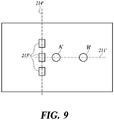
- FIG. 9 is a plan view of the baseplate 210' on which a plurality of optical elements 215' is arranged, according to the first embodiment.
- the number of the optical elements 215' is not limited to three, but can be any number.
- the set position is determined by the first baseline 211' and the second baseline 214'.
- the optical elements 215' are arranged in a row along the second baseline 214'; however, in some embodiments, the optical elements 215' are arranged in a plurality of rows along the second baseline 214'.
- An optical transceiver 1 according to a second embodiment of the present disclosure has a structure similar to the transmission path expander 1' according to the first embodiment.
- FIG. 10 is a perspective view of the optical transceiver 1 according to the second embodiment
- FIG. 11 is a plan view of a baseplate 210 including a first reference hole A and a second reference hole B, on which an optical element 215 is mounted, according to the second embodiment
- FIG. 12 is a schematic diagram for illustrating a method of aligning the optical element 215, according to the second embodiment
- FIG. 13 is a schematic diagram for illustrating an optical alignment of the optical element 215 and a lens unit 320, according to the second embodiment.
- the baseplate 210 includes a first reference hole A and a second reference hole B along a first baseline 211 indicated on the upper surface and the optical element 215 arranged at the intersection of the first baseline 211 and a second baseline 214.
- An optical-fiber-fixing block 300 includes an optical fiber guide portion 310, a lens unit 320, a reflecting member 330, an optical fiber 340, and a first post C and a second post D arranged along a third baseline 350 indicated on the bottom of the optical-fiber-fixing block 300.
- the method of aligning an optical element according to the second embodiment includes a step of preparing the optical element 215 (S210) and a step of preparing the baseplate 210 including a set position for arranging the optical element 215, the first reference hole A, and the second reference hole B formed at the first distance 212 from the first reference hole A (Step S220).
- the set position is determined by the first baseline 211 that passes the first reference hole A and the second reference hole B and the second baseline 214 that intersects with the first baseline 211 at a second distance 213 from the first reference hole A between the first reference hole A and the second reference hole B.
- the second distance 213 is shorter than the first distance 212.
- the method of aligning the optical element 215 further includes steps of preparing the optical-fiber-fixing block 300 including the optical fiber 340 optically coupled with the optical element 215 and the lens unit 320 mounted thereon in a fixed manner, a first post C to be inserted into the first reference hole A, and a second post D to be inserted into the second reference hole B and mounting the optical-fiber-fixing block 300 on the baseplate 210 (Step S230).
- the alignment method according to the second embodiment differs from the first embodiment in the set position where the optical element 215 is arranged. Effects of the second embodiment from this difference are described in detail below.
- the posts C and D are portions protruding on one side of the optical-fiber-fixing block 300.
- the posts C and D are injection molded in an integrated manner with the optical-fiber-fixing block 300.
- the second post D is inserted into the second reference hole B in a looser manner than the first post C is inserted into the first reference hole A.
- the diameter (size) of the second post D is smaller than the diameter (size) of the first post C such that the second post D is inserted into the second reference hole B in a looser manner than the first post C is inserted into the first reference hole A.
- the diameter (size) of the second reference hole B is larger than the diameter (size) of the first reference hole A such that the second post D is inserted into the second reference hole B in a looser manner than the first post C is inserted into the first reference hole A.
- the first reference hole A and the second reference hole B are arranged along the length direction of the optical fiber 340. Further the first post C and the second post D are arranged along the length direction of the optical fiber 340. Unlike the conventional technology in which the hole 104 and the post 105 are arranged on a line extending in the direction of arranging the optical element 115, the arrangement according to the embodiments of the present disclosure can reduce the width of the baseplate 210, reducing an unnecessary space in the optical alignment.
- the method of aligning the optical element 215 according to the second embodiment is further described with reference to FIGS. 10 and 12 .
- the first reference hole A, the second reference hole B, and the optical element 215 are shown on the baseplate 210 in FIG. 10 .
- the coordinate axes are represented such that the length direction of the baseplate 210 is x-axis, the width direction is y-axis, and the thickness direction is z-axis.
- a point O corresponding to the first reference hole A, a point N corresponding to the second reference hole B, and a point M corresponding to the optical element 215 are shown in FIG. 12 .
- the point M, the point N, and the point O are arranged on the first baseline 211.
- An angle ⁇ shown in FIG. 12 is an angle generated from the z-axis as the rotation axis, and a line that forms the angle ⁇ with the first baseline 211 is the third baseline 350 that passes through the first post C and the second post D of the optical-fiber-fixing block 300.
- a line passing through the center of the first post C and the center of the second post D is the third baseline 350.
- the distance between the center of the first post C and the center of the second post D is substantially equal to the first distance 212, and the distance between the center of the first post C and the center of the second post D is substantially equal to the distance between the center of the first reference hole A and the center of the second reference hole B.
- the first post C is tightly inserted into the first reference hole A.
- the second post D is inserted into the second reference hole B in a looser manner than the first post C is inserted into the first reference hole A.
- the second post D is slightly movable in the second reference hole B.
- the third baseline 350 is slightly movable in the clockwise direction or in the counterclockwise direction centering around the z-axis, and hence the first baseline 211 and the third baseline 350 may be coincident with each other or may not be coincident with each other.
- a fourth baseline 216 is formed in a direction parallel to the z-axis.
- the fourth baseline 216 is a virtual line that is perpendicular to the first baseline 211 and the second baseline 214 and that intersects with the second baseline 214.
- the optical element 215 and the lens unit 320 are arranged on the fourth baseline 216. That is, the optical element 215 and the lens unit 320 are arranged on the same axial line.
- a point O' corresponding to the first reference hole A', a point N' corresponding to the second reference hole B', and a point M' corresponding to the optical element 215' are shown in FIG. 5 .
- the point M', the point N', and the point O' are arranged on the first baseline 211'.
- a ratio of a line segment O'M' and a line segment O'N' is equal to a ratio of the distance for which the point M' is moved by Q' and the distance for which the point N' is moved by P'.
- Q' indicates the distance for which the lens unit is moved
- P' indicates the distance for which the post of the optical-fiber-fixing block is slightly moved in the round hole B' in a state in which the post is inserted into the hole B'.
- the third baseline 350 is shown in FIG. 12 , which indicates a slight movement of the optical-fiber-fixing block 300 in the clockwise direction or in the counterclockwise direction by the angle ⁇ with respect to the point O.
- a ratio of a line segment OM and a line segment ON can be represented by a ratio of the distance for which the point M is moved by Q and the distance for which the point N is moved by P.
- the optical element and the lens unit are arranged outside the reference hole in the first embodiment, an interference with neighboring members in relatively free, and hence the manufacturing process can be simplified.
- the method of aligning an optical element with less deviation according to the second embodiment has following effects, which are equivalent to or more than those of the first embodiment.
- a deviation between the lens unit 320 and the optical element 215 generated when aligning them can be reduced.
- a tolerance can be increased when manufacturing the reference holes A and B of the baseplate 210 under this condition, and a component such as the alignment plate 220' of the first embodiment can be eliminated. That is, the first embodiment necessitates the alignment plate 220' due to the stringent precision for the optical alignment of the lens unit 320' and the optical element 215'; however, the second embodiment can eliminate such requirement. This makes the process of manufacturing the components easy, and at the same time, improves the economic feasibility.
- the volume of the entire optical transceiver can be reduced by arranging the optical element 215 between the reference hole A and the reference hole B. This complies with the recent trend of downsizing the information communication devices.
- FIG. 14A is a side view of the optical-fiber-fixing block 300 according to the second embodiment; and FIG. 14B is a plan view of the optical-fiber-fixing block 300 according to the second embodiment.
- the optical fiber 340 can be mounted in the optical-fiber-fixing block 300 in a fixed manner.
- the optical-fiber-fixing block 300 includes the optical fiber guide portion 310 for guiding the optical fiber 340 on the inward side.
- the optical fiber guide portion 310 can be formed in a straight manner or in a tapered manner such that the area is increased from the inner side toward an opening portion on the outer side, to guide the facet of the optical fiber 340 to a predetermined position.
- the optical fiber 340 is settled in the optical-fiber-fixing block 300 by being inserted along the length direction by the settlement length L by the optical fiber guide portion 310.
- the optical fiber 340 needs to ensure the settlement length L for settling the optical fiber 340 in the optical-fiber-fixing block 300 by a predetermined length. By ensuring the settlement length L, the stability and the durability of the optical fiber and the optical transceiver can be achieved.
- the optical fiber guide portion 310 guides the optical fiber 340 to be arranged while ensuring the settlement length L along the length direction.
- the ratio of the second distance 213 to the first distance 212 can be set such that the optical fiber 340 and the optical element 215 are optically aligned with each other within the tolerance range.
- the length direction of the optical fiber 340 settled and mounted in the optical-fiber-fixing block 300 in a fixed manner includes a direction same as the direction of the first baseline 211 or the third baseline 350. As described above, the optical fiber 340 needs the settlement length L of a predetermined length.
- the optical element 215 and the lens unit 320 are arranged on the fourth baseline 216.
- the optical element 215 and the lens unit 320 can be arranged while maintaining the third distance 217.
- FIG. 15 is a plan view of the baseplate 210 on which a plurality of optical elements 215 is arranged, according to the second embodiment.
- FIG. 15 A case where the optical element 215 includes a plurality of optical elements, unlike the embodiment shown in FIG. 11 , is shown in FIG. 15 .
- four optical elements 215 are arranged in a row at regular intervals on the second baseline 214 on the baseplate 210.
- the optical elements 215 are arranged in a plurality of rows along the second baseline 214.
- the number of optical elements 215 can be any number depending on the required specification.
- the configuration and the method of aligning the optical element according to the second embodiment is similar to those of the first embodiment.
- FIG. 16 is a flowchart of a method of aligning an optical element according to a third embodiment of the present disclosure.
- the method of aligning an optical element 215' includes a step of preparing an optical element 215' (Step S210), a step of preparing a baseplate 210' that includes a first reference hole A' and a second reference hole B' (Step S220), a step of arranging the optical element 215' at a position determined based on the first reference hole A' and the second reference hole B' on the baseplate 210' (Step S230), and a step of aligning an optical fiber 340' optically coupled with the optical element 215' and the optical element 215' by mounting an optical-fiber-fixing block 300' including the optical fiber 340', a lens unit 320', a first post C', and a second post D' on the baseplate 210' (Step S240).
- the optical alignment is achieved by the first post C' being inserted into the first reference hole A' and the second post D' being inserted into the second reference hole B'.
- the second post D' is inserted into the second reference hole B' in a looser manner than the first post C' is inserted into the first reference hole A'.
- the position where the optical element 215' is arranged is determined by a first baseline 211' that passes through the first reference hole A' and the second reference hole B' and a second baseline 214' that intersects with the first baseline 211' at a second distance 213' from the first reference hole A' on the opposite side to the second reference hole B' with respect to the first reference hole A'.
- the second distance 213' is shorter than the first distance 212'.
- the diameter (size) of the second post D' is smaller than the diameter (size) of the first post C'.
- the diameter (size) of the second reference hole B' is larger than the diameter (size) of the first reference hole A'.
- the configuration and the method of aligning the optical element according to the third embodiment is similar to those of the first embodiment.
- Steps S110 to S130 and Steps S210 to S240 are described to be sequentially performed in the examples shown in FIGs. 2 and 16 respectively, they merely instantiate a technical idea of some embodiments of the present disclosure. Therefore, a person having ordinary skill in the pertinent art could appreciate that various modifications, additions, and substitutions are possible by changing the sequences described in FIGs. 2 and 16 or by executing two or more steps in parallel, without departing from the gist and nature of the embodiments of the present disclosure, and hence FIGs. 2 and 16 are not limited to the illustrated chronological sequences.
Landscapes
- Physics & Mathematics (AREA)
- General Physics & Mathematics (AREA)
- Optics & Photonics (AREA)
- Optical Couplings Of Light Guides (AREA)
- Chemical & Material Sciences (AREA)
- Crystallography & Structural Chemistry (AREA)
Description
- The present disclosure relates to a method of aligning an optical element, and more particularly, to a method of aligning an optical element by using two round holes on a substrate.
- The statements in this section merely provide background information related to the present disclosure and do not necessarily constitute prior art.
- A signal transmission method based on an optical fiber, which is widely used in a long haul communication, is in widespread use for a large-capacity digital media transmission including a high-definition digital video display device for which high-speed and high-density data transmission is required, owing to the operation characteristics unaffected by an electromagnetic interference (EMI) and usefulness in a broad frequency band of the optical fiber.
- Such a signal transmission method based on the optical fiber can be implemented by arranging a lens and a reflecting member between an optical fiber and an optical element. In order to achieve such configuration, a method of performing an optical alignment can be used by mounting a structure including the optical fiber, the reflecting member, and the lens in a fixed manner on a substrate on which the optical element is mounted.
- In an optical transceiver manufactured by using the above-mentioned optical alignment method, the structure can be simplified, the manufacturing cost can be reduced, and durability and precision can be enhanced depending on how the optical element, the lens, the reflecting member, and the optical fiber are aligned, and hence the optical alignment issue is getting an attention.
- However, an optical transceiver manufactured by performing an optical alignment of the conventional method is not only highly costly but also bulky, causing a problem in using it in a mobile communication apparatus such as a smartphone, in addition to a problem in ensuring the stability due to a complicated structure.
-
FIG. 1 is a schematic diagram for illustrating a conventional method of aligning an optical element. - An injection molded
structure 102 assembled on asubstrate 101 is shown inFIG. 1 . In general, a hole on thesubstrate 101 in order to mount another structure to be connected to thesubstrate 101 is hard to form in a precise manner, and hence the injection moldedstructure 102 including a precise hole is used as a guide. Anoptical element 103 is arranged on thesubstrate 101. Thesubstrate 101 includes tworound holes 104 on a line extending in a direction of arranging theoptical element 103, and the injection moldedstructure 102 includes tworound posts 105. The tworound posts 105 are respectively inserted into theround holes 104, and the optical alignment is achieved by further arranging a lens structure on the assembled injection moldedstructure 102. - Using the conventional technology, an optical alignment error can be reduced to some extent; however, there still are problems in complexity of assembling an additional part, economical feasibility, and increase in volume of the entire structure.
- In addition, due to the characteristics of the structure that hardly provides 100% fitting in the coupling structure of the hole and the post as shown in
FIG. 1 , when the hole and the post are fixed at one side, there exists a tolerance between the hole and the post at the other side. This causes a certain amount of deviation in the optical alignment, which can act as a critical problem in such a technical field that requires high precision. -
US 2013/266262 A1 discloses an optical path changing member comprising a member main body which is made of a transparent material and in which a reflection section optically connecting the optical fiber to the light input and output end is formed. -
US 2013/308910 A1 discloses a ferrule having a ferrule main body with a front edge and a read edge, a fiber insertion hole into which an optical fiber is to be inserted, and a recess provided at a top surface of the ferrule main body. -
JP 2013 047846 A -
US 2008/0036103 A1 discloses an optical module having a package that has optical elements mounted thereon and which is sealed with a transparent plate. -
WO 2013/099415 A1 discloses an optical module detachably attached to a cage, the optical module including a circuit board which is connected to the cage. - Embodiments of the present disclosure have been made in view of the above aspects, and it is an object of the present disclosure to provide a new method of aligning an optical element with an optical fiber based on a first reference hole, a second reference hole, a first baseline, and a second baseline.
- It is another object of the present disclosure to increase the tolerance of the components of the optical transceiver by providing a new method of aligning an optical element, and eventually to downsize the optical transceiver to achieve the economic feasibility, manufacturing convenience, and the like.
- The technical problems to be solved by the present disclosure are not limited to the above-mentioned, but other technical problems not mentioned above can be clearly understood by one of ordinary skill in the pertinent art from the following descriptions.
- An invention is defined in the independent claims.
- In accordance with aspects of the present disclosure, an optical element alignment method includes preparing at least one optical element and preparing a baseplate. The baseplate includes a set position for mounting the at least one optical element, a first reference hole, and a second reference hole spaced by a first distance from the first reference hole.
- In accordance with another aspect of the present disclosure, an optical element alignment method includes preparing at least one optical element, preparing a baseplate including a first reference hole and a second reference hole, mounting the at least one optical element at a position which is determined in the baseplate based on the first reference hole and the second reference hole, and preparing an optical-fiber-fixing block configured to have a first post and a second post and to mount at least an optical fiber optically coupled with the optical element and a lens unit in a fixed manner so as to establish an optical alignment of the optical fiber with the optical element. Here, the optical alignment is established by inserting the second post into the coupled with the optical element and a lens unit in a fixed manner so as to establish an optical alignment of the optical fiber with the optical element. Here, the optical alignment is established by inserting the second post into the second reference hole and inserting the first post into the first reference hole with the second post inserted in a looser manner than the first post is inserted.
- As described above, according to some embodiments of the present disclosure, an optical alignment of an optical element and an optical fiber can be performed with ease and an alignment error can be minimized.
- Further, an optical transceiver manufactured by an alignment method according to some embodiments of the present disclosure can be downsized and manufactured by a simple assembly of inexpensive components, cutting down the manufacturing cost.
- Besides, some embodiments of the present disclosure provide an excellent durability, which will be clearly appreciated from the following description.
-
-
FIG. 1 is a schematic diagram for illustrating a conventional method of aligning an optical element. -
FIG. 2 is a flowchart of a method of aligning an optical element according to a first embodiment of the present disclosure. -
FIG. 3 is a perspective view of an optical transceiver according to the first embodiment. -
FIG. 4A is a plan view of a baseplate including a first reference hole and a second reference hole, on which an optical element is mounted, according to the first embodiment. -
FIG. 4B is a plan view of a baseplate on which an optical element and an alignment plate including a first reference hole and a second reference hole are arranged, according to the first embodiment. -
FIG. 5 is a schematic diagram for illustrating the method of aligning an optical element, according to the first embodiment. -
FIG. 6 is a schematic diagram for illustrating an optical alignment of an optical element and a lens unit, according to the first embodiment. -
FIG. 7A is a top view of an optical-fiber-fixing block according to the first embodiment. -
FIG. 7B is a side view of the optical-fiber-fixing block according to the first embodiment. -
FIG. 8A is a top view of an alignment plate according to the first embodiment. -
FIG. 8B is a side view of the alignment plate according to the first embodiment. -
FIG. 9 is a plan view of the baseplate on which a plurality of optical elements is arranged, according to the first embodiment. -
FIG. 10 is a perspective view of an optical transceiver according to a second embodiment of the present disclosure. -
FIG. 11 is a plan view of a baseplate including a first reference hole and a second reference hole, on which an optical element is mounted, according to the second embodiment. -
FIG. 12 is a schematic diagram for illustrating a method of aligning an optical element, according to the second embodiment. -
FIG. 13 is a schematic diagram for illustrating an optical alignment of an optical element and a lens unit, according to the second embodiment. -
FIG. 14A is a side view of an optical-fiber-fixing block according to the second embodiment. -
FIG. 14B is a plan view of the optical-fiber-fixing block according to the second embodiment. -
FIG. 15 is a plan view of the baseplate on which a plurality of optical elements is arranged, according to the second embodiment. -
FIG. 16 is a flowchart of a method of aligning an optical element according to a third embodiment of the present disclosure. - Exemplary embodiments of the present disclosure are described in detail below with reference to the accompanying drawings. In the following descriptions, like reference numerals designate like elements although the elements are shown in different drawings. Further, detailed descriptions of known functions and configurations incorporated herein are omitted for the purpose of clarity and for brevity.
- Additionally, various terms such as first, second, A, B, etc., are used solely for the purpose of differentiating one component from the other but not to imply or suggest the substances, the order or sequence of the components. In the entire specification, when a portion "comprises" or "includes" a constituent element, this does not mean to exclude another constituent element unless otherwise described particularly in view of the opposite aspect but means that another constituent element can be further included. In addition, terms such as "... unit" described in the specification means a unit of processing at least one function or operation, which can be implemented by hardware, software, or a combination of hardware and software.
- If a component were described as 'connected', 'coupled', or 'linked' to another component, they may mean the components are not only directly 'connected', 'coupled', or 'linked' but also are indirectly 'connected', 'coupled', or 'linked' via one or more additional components.
- In addition, size and shape of a constituent element shown in the drawings may be exaggerated for the sake of clear description and convenience. Further, terms specially defined considering configuration and operation of the present disclosure are merely for describing embodiments of the present disclosure, but not limiting the scope of the present disclosure.
- The following embodiments exemplify the present disclosure.
- In describing constituents of some embodiments of the present disclosure with reference to the drawings, like reference numerals designate like constituents. For example, a baseplate may be designated 210' in a first embodiment, and 210 in a second embodiment.
- Further, detailed descriptions presented in the first embodiment as to functions and configurations will be omitted from subsequent embodiments not to repeat the same details.
-
FIG. 2 is a flowchart of a method of aligning an optical element according to a first embodiment of the present disclosure;FIG. 3 is a perspective view of an optical transceiver 1' according to the first embodiment;FIG. 4A is a plan view of a baseplate 210' including a first reference hole A' and a second reference hole B', on which an optical element 215' is mounted, according to the first embodiment; andFIG. 4B is a plan view of a baseplate 210' on which the optical element 215' and an alignment plate 220' including the first reference hole A' and the second reference hole B' are arranged, according to the first embodiment. - Before describing the method of aligning an optical element according to the first embodiment, a configuration of the optical transceiver 1' according to the first embodiment is briefly described. The optical transceiver 1' according to the first embodiment is also referred to as a transmission path expander 1'.
- As shown in
FIG. 3 , in some embodiments, the transmission path expander 1' includes a baseplate 210', an optical-fiber-fixing block 300', and a housing 400'. In some embodiments, the transmission path expander 1' further includes an alignment plate 220' including a mounting portion for mounting the alignment plate 220' on the baseplate 210', a first reference hole A', and a second reference hole B' formed at a first distance 212' from the first reference hole A'. - Referring to
FIG. 2 , the method of aligning the optical element 215' according to the first embodiment includes a step of preparing the optical element 215' (Step S110) and a step of preparing the baseplate 210' including a set position for arranging the optical element 215', the first reference hole A', and the second reference hole B' formed at the first distance 212' from the first reference hole A' (Step S120). - The set position is determined by a first baseline 211' that passes the first reference hole A' and the second reference hole B' and a second baseline 214' that intersects with the first baseline 211' at a second distance 213' from the first reference hole A' on the opposite side to the second reference hole B' with respect to the first reference hole A'. That is, the first reference hole A' is sandwiched by the second baseline 214' and the second reference hole B'. In some embodiments, the second distance 213' is shorter than the first distance 212'.
- The baseplate 210' is described in detail below with reference to
FIGS. 4A and4B . - In some embodiments, the baseplate 210' is a printed circuit board (PCB).
- The set position is a portion of the baseplate 210' where the optical element 215' is mounted. In some embodiments, the optical element 215' includes a plurality of optical elements, and in this case, the plurality of optical elements is arranged at the set position. In some embodiments, each of the first reference hole A' and the second reference hole B' is a through hole that passes through the baseplate 210' or the alignment plate 220' from one side to the other side. In some embodiments, each of the first reference hole A' and the second reference hole B' is a recessed structure formed on the baseplate 210' or the alignment plate 220' with a predetermined depth.
- In some embodiments, the first baseline 211' and the second baseline 214' are virtual lines, and the set position is determined based on the first baseline 211' and the second baseline 214'.
- In some embodiments, the set position is on the second baseline 214'. That is, the optical element 215' is mounted on the second baseline 214' on the baseplate 210'. In some embodiments, the optical element 215' is arranged at an intersection of the first baseline 211' and the second baseline 214'.
- When the optical element 215' includes a single optical element, as shown in
FIG. 4A , the center of a light emitting portion or a light receiving portion of the optical element 215' is located at a point where the first baseline 211' and the second baseline 214' intersect with each other at right angles. When the optical element 215' includes a plurality of optical elements, the plurality of optical elements is arranged in a row or in a plurality of rows on the second baseline 214' along the length direction of the second baseline 214'. - The first baseline 211' is determined by the first reference hole A' and the second reference hole B'. That is, a line that passes through the first reference hole A' and the second reference hole B' is taken as the first baseline 211'. In some embodiments, a line that passes through the center of the first reference hole A' and the center of the second reference hole B' is taken as the first baseline 211'. In this case, a distance between the center of the first reference hole A' and the center of the second reference hole B' is defined as the first distance 212'.
- The second baseline 214' is determined by the first baseline 211', the first reference hole A', and the second distance 213'. The second baseline 214' intersects with the first baseline 211' on the baseplate 210'. In some embodiments, the second baseline 214' intersects with the first baseline 211' at right angles on the baseplate 210'.
- In the first embodiment, the second baseline 214' is located on the opposite side to the second reference hole B', sandwiching the first reference hole A' therebetween, and intersects with the first baseline 211' at the second distance 213' from the first reference hole A'. In this case, the second distance 213' is shorter than the first distance 212'.
- In order to determine the set position for arranging the optical element 215' on the baseplate 210', the first reference hole A' and the second reference hole B' are needed. However, when the baseplate 210' is a PCB, it is hard to form the first reference hole A' and the second reference hole B' with precise position and size.
- Therefore, in some embodiments, the first reference hole A' and the second reference hole B' are provided on the baseplate 210' by mounting the alignment plate 220', on which the first reference hole A' and the second reference hole B' are precisely formed, on the baseplate 210'. That is, the alignment plate 220' serves the precisely-formed first reference hole A' and second reference hole B' to the baseplate 210'. The first reference hole A' and the second reference hole B' formed on the alignment plate 220' can be used as the reference for determining the set position on the baseplate 210'. The baseplate 210' with the alignment plate 220' arranged thereon is shown in
FIG. 4B . - In the first embodiment, the method for aligning an optical element further includes steps of preparing an optical-fiber-fixing block 300' including an optical fiber 340' optically coupled with the optical element 215' and a
lens unit 320' mounted thereon in a fixed manner, a first post C' to be inserted into the first reference hole A', and a second post D' to be inserted into the second reference hole B' and mounting the optical-fiber-fixing block 300' on the baseplate 210' (Step S130). In some embodiments, the second post D' is inserted into the second reference hole B' in a looser manner than the first post C' is inserted into the first reference hole A'. - In some embodiments, the first reference hole A' and the second reference hole B' are arranged in the length direction of the optical fiber 340'. Further, the first post C' and the second post D' are arranged along the length direction of the optical fiber 340'. In this case, the length direction of the optical fiber 340' means the length direction of a portion of the optical fiber 340' that is mounted on the optical-fiber-fixing block 300' in a fixed manner. Such an arrangement reduces an unnecessary space in the optical alignment.
- When the first reference hole A' and the second reference hole B' are formed on the alignment plate 220', the optical-fiber-fixing block 300' and the alignment plate 220' are coupled with each other by the first post C' being inserted into the first reference hole A' and the second post D' being inserted into the second reference hole B'. The first post C' is tightly inserted into the first reference hole A'. However, the second post D' is inserted into the second reference hole B' in s looser manner than the first post C' is inserted into the first reference hole A'.
- In some embodiments, the diameter (size) of the second post D' is smaller than the diameter (size) of the first post C'. In some embodiments, the diameter (size) of the second reference hole B' is larger than the diameter (size) of the first reference hole A'.
-
FIG. 5 is a schematic diagram for illustrating the method of aligning an optical element, according to the first embodiment; andFIG. 6 is a schematic diagram for illustrating an optical alignment of the optical element 215' and thelens unit 320', according to the first embodiment. - In
FIG. 6 , a process of aligning the optical element 215' and thelens unit 320' when the optical element 215' includes a single optical element arranged on the baseplate 210' is described. - The optical element 215' is arranged at a point on the first baseline 211' apart from the first reference hole A' by the second distance 213'.
- A line passing through the first post C' and the second post D' formed on the bottom of the optical-fiber-fixing block 300' is defined as a third baseline 350'. In some embodiments, a line passing through the center of the first post C' and the center of the second post D' is defined as the third baseline 350', and a distance between the center of the first post C' and the center of the second post D' is defined as the first distance 212'. That is, the distance between the center of the first post C' and the center of the second post D' is substantially equal to the distance between the center of the first reference hole A' and the center of the second reference hole B'.
- The
lens unit 320' is arranged on the third baseline 350' on a plan view of the optical-fiber-fixing block 300'. Specifically, thelens unit 320' is arranged on the third baseline 350' at the second distance 213' from the first post C'. - When the optical-fiber-fixing block 300' is mounted on the baseplate 210' or the alignment plate 220', the first post C' is tightly inserted into the first reference hole A'. However, the second post D' is inserted into the second reference hole B' in a looser manner than the first post C' is inserted into the first reference hole A'. Hence the second post D' is slightly movable in the second reference hole B'.
- In consequence, the third baseline 350' is slightly movable in the clockwise direction or in the counterclockwise direction centering around the first reference hole A', and hence the first baseline 211' and the third baseline 350' may be coincident with each other or may not be coincident with each other.
- A virtual line perpendicular to the first baseline 211' and the second baseline 214' and intersecting with the second baseline 214' is defined as a fourth baseline 216', and then, when the first baseline 211' and the third baseline 350' are coincident with each other, the optical element 215' and the
lens unit 320' are arranged on the fourth baseline 216'. That is, the optical element 215' and thelens unit 320' are arranged on the same axial line. - In the first embodiment, the second distance 213' is shorter than the first distance 212'. That is, with respect to the first post C', the second post D' is relatively far and the
lens unit 320' is relatively near, and hence even when a movement of the second post D' is large in the second reference hole B', a movement of thelens unit 320' is relatively small. Therefore, even when the first baseline 211' and the third baseline 350' are not coincident with each other at the second post D', a deviation between the optical element 215' and thelens unit 320' is relatively slight. - A ratio of the second distance 213' to the first distance 212' can be set in such a manner that the optical fiber 340' and the
lens unit 320' are optically aligned with the optical element 215' within a tolerance range. The larger the difference between the first distance 212' and the second distance 213' is, the smaller a ratio of the movement of thelens unit 320' to the movement of the second post D' is. Therefore, a more precise alignment can be obtained by increasing the difference between the first distance 212' and the second distance 213'. - In some embodiments, the first distance 212' and the second distance 213' are not fixed in advance. A optical designer can set the first distance 212' and the second distance 213' to appropriate values and the ratio of the second distance 213' to the first distance 212' to an appropriate value, in such a manner that the optical element 215' and the optical fiber 340' are optically aligned with each other within a tolerance range according to a required specification.
- In the first embodiment, by adopting a structure in which the second post D' is inserted into the second reference hole B' in a looser manner than the first post C' is inserted into the first reference hole A', a deformation can be prevented from being generated, which is normally generated when forcibly fitting the optical-fiber-fixing block 300' into the alignment plate 220' or the baseplate 210'. Accordingly, a precise optical alignment can be obtained and the durability can be improved.
- In some embodiments, the
lens unit 320', a reflecting member 330', and the optical fiber 340' are arranged in the optical-fiber-fixing block 300' in an optically aligned manner. The reflecting member 330' is, for example, a mirror or a prism. - The optical alignment allows light emitted from a facet of the optical fiber 340' to be deflected via the reflecting member 330' and to be focused onto the optical element 215' via the
lens unit 320' or allows light emitted from the optical element 215' to be collimated or focused via thelens unit 320' and to be deflected via the reflecting member 330' such that the light reaches the facet of the optical fiber 340'. The former case where the optical element 215' is a light receiving element is shown inFIG. 6 . For the latter case where the optical element 215' is a light emitting element, in some embodiments, the similar structure as the one shown inFIG. 6 can be used, and in some embodiments, a focusing lens is further used between the reflecting member 330' and the optical fiber 340'. - When the first baseline 211' and the third baseline 350' are coincident with each other, the optical element 215' and the
lens unit 320' are arranged on the fourth baseline 216'. In this case, the optical element 215' and thelens unit 320' are arranged with a third distance 217' therebetween. The optical designer can set the third distance 217'. - When the alignment plate 220' is not used, the third distance 217' can be determined by the height from the bottom of the optical-fiber-fixing block 300' to the
lens unit 320'. When the alignment plate 220' is used, the third distance 217' can be determined by a distance obtained by adding the height of the alignment plate 220' to the height from the bottom of the optical-fiber-fixing block 300' to thelens unit 320'. An operator can arrange the optical element 215' and thelens unit 320' with the third distance 217' maintained simply by coupling the optical-fiber-fixing block 300' with the fixed height or the combined structure of the optical-fiber-fixing block 300' and the alignment plate 220' with the baseplate 210'. - Referring back to
FIG. 3 , when the virtual line passing through the first post C' and the second post D' is defined as the third baseline 350', fixing posts for fixing the alignment plate 220' onto the baseplate 210' can be formed on the third baseline 350' in a row. With this structure, the volume of the transmission path expander 1' can be reduced. This will be described later. - The optical-fiber-fixing block 300' and the alignment plate 220' are described in more detail below.
-
FIG. 7A is a top view of the optical-fiber-fixing block 300' according to the first embodiment; andFIG. 7B is a side view of the optical-fiber-fixing block 300' according to the first embodiment. - In some embodiments, the optical fiber 340' is inserted into the optical-fiber-fixing block 300' by an optical fiber guide portion 310' by a settlement length L' along the length direction. By ensuring the settlement length L' for settling the optical fiber 340' in the optical-fiber-fixing block 300', stability and durability of the optical transceiver can be achieved. The optical fiber guide portion 310' guides the optical fiber 340' such that the optical fiber 340' is arranged while ensuring the settlement length L' along the length direction.
- In some embodiments, one side of the optical-fiber-fixing block 300' includes a protruded portion 360' protruding in the length direction of the optical fiber 340', and the
lens unit 320' is mounted on the bottom of the protruded portion 360' in a fixed manner facing downward. That is, thelens unit 320' is mounted in a fixed manner to face a direction perpendicular to the length direction of the optical fiber 340'. By mounting this structure on the baseplate 210', the optical element 215' arranged at the set position of the baseplate 210' and thelens unit 320' can face each other. - In some embodiments, the length direction of optical fiber 340' settled and mounted in a fixed manner in the optical-fiber-fixing block 300' includes a direction same as the direction of the first baseline 211' or the third baseline 350'. As described above, the optical fiber 340' needs the settlement length L' of a predetermined length. Therefore, when the first post C', the second post D', the first reference hole A', and the second reference hole B' are arranged along the length direction, the first post C', the second post D', the first reference hole A', and the second reference hole B' share the space needed for the optical fiber 340', and hence the optical transceiver can be downsized.
-
FIG. 8A is a top view of the alignment plate 220' according to the first embodiment; andFIG. 8B is a side view of the alignment plate 220' according to the first embodiment. - At least two fixing posts (or mounting portions) 221' are formed on the bottom of the alignment plate 220', and fixing holes are formed on the upper surface of the baseplate 210' at locations respectively corresponding to the fixing posts 221'. Therefore, the alignment plate 220' can be mounted on the baseplate 210' by the fixing posts 221' being inserted into the fixing holes. In this case, the fixing posts 221' and the fixing holes are arranged on the first baseline 211' in a row. With this structure, the volume of the optical transceiver manufactured by the alignment method according to some embodiments of the present disclosure can be reduced.
- Although the first reference hole A' and the second reference hole B' should be processed in a precise manner, the alignment plate 220' itself is not necessarily to be manufactured in a precise manner. Therefore, the alignment plate 220' can be mass manufactured with low cost by using a plastic injection molding method. The mounting portions formed on the bottom of the alignment plate 220' are not necessarily to be manufactured in a precise manner, either. A manufacture can achieve an optical alignment of the optical element 215' and the optical fiber 340' simply by coupling the optical-fiber-fixing block 300' with the baseplate 210' on which the optical element 215' is mounted.
-
FIG. 9 is a plan view of the baseplate 210' on which a plurality of optical elements 215' is arranged, according to the first embodiment. - Although three optical elements 215' are shown in
FIG. 9 , the number of the optical elements 215' is not limited to three, but can be any number. As described above, the set position is determined by the first baseline 211' and the second baseline 214'. As shown inFIG. 9 , the optical elements 215' are arranged in a row along the second baseline 214'; however, in some embodiments, the optical elements 215' are arranged in a plurality of rows along the second baseline 214'. - An
optical transceiver 1 according to a second embodiment of the present disclosure has a structure similar to the transmission path expander 1' according to the first embodiment. -
FIG. 10 is a perspective view of theoptical transceiver 1 according to the second embodiment;FIG. 11 is a plan view of abaseplate 210 including a first reference hole A and a second reference hole B, on which anoptical element 215 is mounted, according to the second embodiment;FIG. 12 is a schematic diagram for illustrating a method of aligning theoptical element 215, according to the second embodiment; andFIG. 13 is a schematic diagram for illustrating an optical alignment of theoptical element 215 and alens unit 320, according to the second embodiment. - The
baseplate 210 according to the second embodiment shown inFIG. 10 includes a first reference hole A and a second reference hole B along afirst baseline 211 indicated on the upper surface and theoptical element 215 arranged at the intersection of thefirst baseline 211 and asecond baseline 214. An optical-fiber-fixingblock 300 includes an opticalfiber guide portion 310, alens unit 320, a reflectingmember 330, anoptical fiber 340, and a first post C and a second post D arranged along athird baseline 350 indicated on the bottom of the optical-fiber-fixingblock 300. - Referring to
FIGS. 2 ,10 , and11 , the method of aligning an optical element according to the second embodiment includes a step of preparing the optical element 215 (S210) and a step of preparing thebaseplate 210 including a set position for arranging theoptical element 215, the first reference hole A, and the second reference hole B formed at thefirst distance 212 from the first reference hole A (Step S220). - The set position is determined by the
first baseline 211 that passes the first reference hole A and the second reference hole B and thesecond baseline 214 that intersects with thefirst baseline 211 at asecond distance 213 from the first reference hole A between the first reference hole A and the second reference hole B. In some embodiments, thesecond distance 213 is shorter than thefirst distance 212. - In the second embodiment, the method of aligning the
optical element 215 further includes steps of preparing the optical-fiber-fixingblock 300 including theoptical fiber 340 optically coupled with theoptical element 215 and thelens unit 320 mounted thereon in a fixed manner, a first post C to be inserted into the first reference hole A, and a second post D to be inserted into the second reference hole B and mounting the optical-fiber-fixingblock 300 on the baseplate 210 (Step S230). - The alignment method according to the second embodiment differs from the first embodiment in the set position where the
optical element 215 is arranged. Effects of the second embodiment from this difference are described in detail below. - In the second embodiment, the posts C and D are portions protruding on one side of the optical-fiber-fixing
block 300. In some embodiments, the posts C and D are injection molded in an integrated manner with the optical-fiber-fixingblock 300. - The second post D is inserted into the second reference hole B in a looser manner than the first post C is inserted into the first reference hole A. In some embodiments, the diameter (size) of the second post D is smaller than the diameter (size) of the first post C such that the second post D is inserted into the second reference hole B in a looser manner than the first post C is inserted into the first reference hole A. In some embodiments, the diameter (size) of the second reference hole B is larger than the diameter (size) of the first reference hole A such that the second post D is inserted into the second reference hole B in a looser manner than the first post C is inserted into the first reference hole A.
- In the same manner as the first embodiment, the first reference hole A and the second reference hole B are arranged along the length direction of the
optical fiber 340. Further the first post C and the second post D are arranged along the length direction of theoptical fiber 340. Unlike the conventional technology in which thehole 104 and thepost 105 are arranged on a line extending in the direction of arranging the optical element 115, the arrangement according to the embodiments of the present disclosure can reduce the width of thebaseplate 210, reducing an unnecessary space in the optical alignment. - The method of aligning the
optical element 215 according to the second embodiment is further described with reference toFIGS. 10 and12 . - The first reference hole A, the second reference hole B, and the
optical element 215 are shown on thebaseplate 210 inFIG. 10 . The coordinate axes are represented such that the length direction of thebaseplate 210 is x-axis, the width direction is y-axis, and the thickness direction is z-axis. - A point O corresponding to the first reference hole A, a point N corresponding to the second reference hole B, and a point M corresponding to the
optical element 215 are shown inFIG. 12 . In some embodiments, the point M, the point N, and the point O are arranged on thefirst baseline 211. - An angle θ shown in
FIG. 12 is an angle generated from the z-axis as the rotation axis, and a line that forms the angle θ with thefirst baseline 211 is thethird baseline 350 that passes through the first post C and the second post D of the optical-fiber-fixingblock 300. In some embodiments, a line passing through the center of the first post C and the center of the second post D is thethird baseline 350. - In some embodiments, the distance between the center of the first post C and the center of the second post D is substantially equal to the
first distance 212, and the distance between the center of the first post C and the center of the second post D is substantially equal to the distance between the center of the first reference hole A and the center of the second reference hole B. - When the optical-fiber-fixing
block 300 is mounted on thebaseplate 210, the first post C is tightly inserted into the first reference hole A. However, the second post D is inserted into the second reference hole B in a looser manner than the first post C is inserted into the first reference hole A. Hence the second post D is slightly movable in the second reference hole B. - In consequence, the
third baseline 350 is slightly movable in the clockwise direction or in the counterclockwise direction centering around the z-axis, and hence thefirst baseline 211 and thethird baseline 350 may be coincident with each other or may not be coincident with each other. - A
fourth baseline 216 is formed in a direction parallel to the z-axis. Thefourth baseline 216 is a virtual line that is perpendicular to thefirst baseline 211 and thesecond baseline 214 and that intersects with thesecond baseline 214. When thefirst baseline 211 and thethird baseline 350 are coincident with each other, theoptical element 215 and thelens unit 320 are arranged on thefourth baseline 216. That is, theoptical element 215 and thelens unit 320 are arranged on the same axial line. - Features of the second embodiment are described in detail below with reference to the first embodiment.
- The concept of the method of aligning an optical element is shown in
FIG. 5 . - A point O' corresponding to the first reference hole A', a point N' corresponding to the second reference hole B', and a point M' corresponding to the optical element 215' are shown in
FIG. 5 . The point M', the point N', and the point O' are arranged on the first baseline 211'. - When the optical-fiber-fixing block is slightly moved in the clockwise direction or in the counterclockwise direction by an angle θ' with respect to the point O', a movement of the axis in the length direction of the optical-fiber-fixing block is indicated by the third baseline 350'. A ratio of a line segment O'M' and a line segment O'N' is equal to a ratio of the distance for which the point M' is moved by Q' and the distance for which the point N' is moved by P'. Q' indicates the distance for which the lens unit is moved, and P' indicates the distance for which the post of the optical-fiber-fixing block is slightly moved in the round hole B' in a state in which the post is inserted into the hole B'.
- In contrast, in the second embodiment, the
third baseline 350 is shown inFIG. 12 , which indicates a slight movement of the optical-fiber-fixingblock 300 in the clockwise direction or in the counterclockwise direction by the angle θ with respect to the point O. A ratio of a line segment OM and a line segment ON can be represented by a ratio of the distance for which the point M is moved by Q and the distance for which the point N is moved by P. - Comparing this with the example shown in
FIG. 5 , if other conditions are the same (particularly, if P' and P have the same value), values Q and Q' that represent a deviation of the lens unit when there is a movement by P shows a relationship of Q'>Q, and hence in the case of the embodiments of the present disclosure, the deviation of the lens unit is smaller than that in the example shown inFIG. 5 . - On the contrary, as the optical element and the lens unit are arranged outside the reference hole in the first embodiment, an interference with neighboring members in relatively free, and hence the manufacturing process can be simplified.
- Therefore, one of ordinary skill in the pertinent art can select a desired mode by combining the embodiments shown in
FIG. 12 andFIG. 5 , and both cases are based on the similar technical idea. - As described above, the method of aligning an optical element with less deviation according to the second embodiment has following effects, which are equivalent to or more than those of the first embodiment.
- Firstly, a deviation between the
lens unit 320 and theoptical element 215 generated when aligning them can be reduced. Secondary, if the deviation between thelens unit 320 and theoptical element 215 is within the tolerance range, a tolerance can be increased when manufacturing the reference holes A and B of thebaseplate 210 under this condition, and a component such as the alignment plate 220' of the first embodiment can be eliminated. That is, the first embodiment necessitates the alignment plate 220' due to the stringent precision for the optical alignment of thelens unit 320' and the optical element 215'; however, the second embodiment can eliminate such requirement. This makes the process of manufacturing the components easy, and at the same time, improves the economic feasibility. In addition, the volume of the entire optical transceiver can be reduced by arranging theoptical element 215 between the reference hole A and the reference hole B. This complies with the recent trend of downsizing the information communication devices. -
FIG. 14A is a side view of the optical-fiber-fixingblock 300 according to the second embodiment; andFIG. 14B is a plan view of the optical-fiber-fixingblock 300 according to the second embodiment. - The
optical fiber 340 can be mounted in the optical-fiber-fixingblock 300 in a fixed manner. The optical-fiber-fixingblock 300 includes the opticalfiber guide portion 310 for guiding theoptical fiber 340 on the inward side. The opticalfiber guide portion 310 can be formed in a straight manner or in a tapered manner such that the area is increased from the inner side toward an opening portion on the outer side, to guide the facet of theoptical fiber 340 to a predetermined position. - The
optical fiber 340 is settled in the optical-fiber-fixingblock 300 by being inserted along the length direction by the settlement length L by the opticalfiber guide portion 310. Theoptical fiber 340 needs to ensure the settlement length L for settling theoptical fiber 340 in the optical-fiber-fixingblock 300 by a predetermined length. By ensuring the settlement length L, the stability and the durability of the optical fiber and the optical transceiver can be achieved. The opticalfiber guide portion 310 guides theoptical fiber 340 to be arranged while ensuring the settlement length L along the length direction. - The ratio of the
second distance 213 to thefirst distance 212 can be set such that theoptical fiber 340 and theoptical element 215 are optically aligned with each other within the tolerance range. - In some embodiments, the length direction of the
optical fiber 340 settled and mounted in the optical-fiber-fixingblock 300 in a fixed manner includes a direction same as the direction of thefirst baseline 211 or thethird baseline 350. As described above, theoptical fiber 340 needs the settlement length L of a predetermined length. - When the
first baseline 211 and thethird baseline 350 are coincident with each other, theoptical element 215 and thelens unit 320 are arranged on thefourth baseline 216. In this case, theoptical element 215 and thelens unit 320 can be arranged while maintaining thethird distance 217. -
FIG. 15 is a plan view of thebaseplate 210 on which a plurality ofoptical elements 215 is arranged, according to the second embodiment. - A case where the
optical element 215 includes a plurality of optical elements, unlike the embodiment shown inFIG. 11 , is shown inFIG. 15 . InFIG. 15 , fouroptical elements 215 are arranged in a row at regular intervals on thesecond baseline 214 on thebaseplate 210. In some embodiments, unlike the example shown inFIG. 15 , theoptical elements 215 are arranged in a plurality of rows along thesecond baseline 214. The number ofoptical elements 215 can be any number depending on the required specification. - Other than the above-mentioned features, the configuration and the method of aligning the optical element according to the second embodiment is similar to those of the first embodiment.
-
FIG. 16 is a flowchart of a method of aligning an optical element according to a third embodiment of the present disclosure. - The method of aligning an optical element 215' according to the third embodiment includes a step of preparing an optical element 215' (Step S210), a step of preparing a baseplate 210' that includes a first reference hole A' and a second reference hole B' (Step S220), a step of arranging the optical element 215' at a position determined based on the first reference hole A' and the second reference hole B' on the baseplate 210' (Step S230), and a step of aligning an optical fiber 340' optically coupled with the optical element 215' and the optical element 215' by mounting an optical-fiber-fixing block 300' including the optical fiber 340', a
lens unit 320', a first post C', and a second post D' on the baseplate 210' (Step S240). - The optical alignment is achieved by the first post C' being inserted into the first reference hole A' and the second post D' being inserted into the second reference hole B'. In this case, the second post D' is inserted into the second reference hole B' in a looser manner than the first post C' is inserted into the first reference hole A'.
- The position where the optical element 215' is arranged is determined by a first baseline 211' that passes through the first reference hole A' and the second reference hole B' and a second baseline 214' that intersects with the first baseline 211' at a second distance 213' from the first reference hole A' on the opposite side to the second reference hole B' with respect to the first reference hole A'. In some embodiments, the second distance 213' is shorter than the first distance 212'.
- In some embodiments, the diameter (size) of the second post D' is smaller than the diameter (size) of the first post C'.
- In some embodiments, the diameter (size) of the second reference hole B' is larger than the diameter (size) of the first reference hole A'.
- Other than the above-mentioned features, the configuration and the method of aligning the optical element according to the third embodiment is similar to those of the first embodiment.
- The present disclosure should not be limited to these embodiments but various changes and modifications are made by one ordinarily skilled in the art within the subject matter, the scope of the present disclosure as hereinafter claimed. Specific terms used in this disclosure and drawings are used for illustrative purposes and not to be considered as limitations of the present disclosure. Exemplary embodiments of the present disclosure have been described for the sake of brevity and clarity. Accordingly, one of ordinary skill would understand the scope of the claimed invention is not to be limited by the explicitly described above embodiments but by the claims.
- Although Steps S110 to S130 and Steps S210 to S240 are described to be sequentially performed in the examples shown in
FIGs. 2 and16 respectively, they merely instantiate a technical idea of some embodiments of the present disclosure. Therefore, a person having ordinary skill in the pertinent art could appreciate that various modifications, additions, and substitutions are possible by changing the sequences described inFIGs. 2 and16 or by executing two or more steps in parallel, without departing from the gist and nature of the embodiments of the present disclosure, and henceFIGs. 2 and16 are not limited to the illustrated chronological sequences.Reference Signs List 101: Substrate 102: Injection molded structure 103: Optical element 104: Round post 105: Round hole 210: Baseplate 211', 211: First baseline 212'212: First distance 213', 213: Second distance 214', 214: Second baseline 215', 215: Optical element 216', 216: Fourth baseline 217', 217: Third distance 300', 300: Optical-fiber-fixing block 310', 310: Optical fiber guide portion 320', 320: Lens unit 330', 330: Reflecting member 340' 340: Optical fiber 350', 350: Third baseline 400': Housing A', A: First reference hole B', B: Second reference hole C', C: First post D', D: Second post
Claims (11)
- An optical element alignment method, comprising:preparing at least one optical element (215');preparing a baseplate (210') including:a set position for mounting the at least one optical element,a first reference hole (A'), anda second reference hole (B') spaced apart in a first direction from the first reference hole by a first distance; andpreparing an optical-fiber-fixing block (300') configured to mount at least an optical fiber (340') optically coupled with the optical element and a lens unit (320') in a fixed manner;wherein the set position is determined by a first baseline (211') that passes through the first reference hole and the second reference hole and by a second baseline (214') that intersects with the first baseline at a second distance from the first reference hole, the set position being located at the intersection of the first baseline and the second baseline, the second distance being either in the first direction or in a second direction which is opposite to the first direction;wherein the optical-fiber-fixing block includes:a first post (C') configured to be inserted into the first reference hole, anda second post (D') configured to be inserted into the second reference hole;wherein a line passing through the first post and the second post is defined as a third baseline 350';wherein the optical-fiber-fixing block is installed so that the second post is inserted into the second reference hole in a looser manner than the first post is inserted into the first reference hole, causing the second post (D') to be movable in the second reference hole (B') and the third baseline 350' to be movable in the clockwise direction or in the counterclockwise direction centering around the first reference hole (A'); andwherein the second distance is shorter than the first distance.
- The optical element alignment method of claim 1, further comprising preparing an alignment plate (220') configured to be mounted on the baseplate (210'), wherein
the first reference hole (A') and the second reference hole (B') are formed on the alignment plate. - The optical element alignment method of claim 2, wherein
the alignment plate (220') includes at least two fixing posts (221'),
the baseplate further includes fixing holes respectively corresponding to the at least two fixing posts, and
the alignment plate is configured to be mounted on the baseplate by the at least two fixing posts being respectively inserted into the fixing holes. - The optical element alignment method of claim 3, wherein the fixing posts (221') and the fixing holes are on the first baseline (211').
- The optical element alignment method of claim 2, wherein the alignment plate (220') is injection-molded.
- The optical element alignment method of claim 1, wherein a ratio of the second distance to the first distance is set so that the optical fiber (340') and the lens unit (320') are optically aligned with the optical element (215') within a tolerance range.
- The optical element alignment method of claim 1, wherein the second reference hole (B') is larger in diameter than the first reference hole (A').
- The optical element alignment method of claim 1, wherein the second post (D') is smaller in diameter than the first post (C').
- The optical element alignment method of claim 1, wherein a length direction of the optical fiber (340') mounted in the optical-fiber-fixing block (300') includes a direction same as a direction of the first baseline (211').
- The optical element alignment method of claim 1, wherein the at least one optical element (215') includes a plurality of optical elements.
- The optical element alignment method of claim 10, wherein the plurality of optical elements are configured to be mounted on the baseplate (210') along the second baseline (214') or are arranged in a plurality of rows along the second baseline.
Applications Claiming Priority (2)
| Application Number | Priority Date | Filing Date | Title |
|---|---|---|---|
| KR20130146596A KR101502318B1 (en) | 2013-11-28 | 2013-11-28 | Optical Element Alignment |
| PCT/KR2014/011589 WO2015080529A1 (en) | 2013-11-28 | 2014-11-28 | Optical element alignment method |
Publications (3)
| Publication Number | Publication Date |
|---|---|
| EP3076216A1 EP3076216A1 (en) | 2016-10-05 |
| EP3076216A4 EP3076216A4 (en) | 2017-07-26 |
| EP3076216B1 true EP3076216B1 (en) | 2020-06-03 |
Family
ID=53027472
Family Applications (1)
| Application Number | Title | Priority Date | Filing Date |
|---|---|---|---|
| EP14865985.7A Active EP3076216B1 (en) | 2013-11-28 | 2014-11-28 | Optical element alignment method |
Country Status (6)
| Country | Link |
|---|---|
| US (1) | US9423569B2 (en) |
| EP (1) | EP3076216B1 (en) |
| JP (1) | JP6106284B2 (en) |
| KR (1) | KR101502318B1 (en) |
| CN (1) | CN106104339B (en) |
| WO (1) | WO2015080529A1 (en) |
Families Citing this family (16)
| Publication number | Priority date | Publication date | Assignee | Title |
|---|---|---|---|---|
| KR101480025B1 (en) | 2013-11-28 | 2015-01-07 | (주)옵토마인드 | Transmission Path Extender |
| KR101689398B1 (en) * | 2014-11-28 | 2016-12-23 | (주)옵토마인드 | Apparatus for Optical Transmitting and Receiving |
| KR101797549B1 (en) * | 2015-12-15 | 2017-12-13 | (주)옵토마인드 | Light transmitter for optical cable and arrangement method therefor |
| US10409015B1 (en) | 2015-12-15 | 2019-09-10 | Optomind Inc. | Optical receiving device including focusing lens and reflector mounted to housing body and collimating lens mounted to housing cover |
| KR101821138B1 (en) * | 2015-12-15 | 2018-03-09 | (주)옵토마인드 | Light receiver for optical cable and arrangement method therefor |
| WO2017105110A1 (en) | 2015-12-15 | 2017-06-22 | (주)옵토마인드 | Transmitting and receiving device for optical cable and alignment method thereof |
| US9715071B1 (en) | 2016-09-12 | 2017-07-25 | Yottahn, Inc. | Bending type optical module and method of manufacturing the same |
| US9645331B1 (en) | 2016-09-12 | 2017-05-09 | Yottahn, Inc. | Optical module device and method of manufacturing the same |
| US9772458B1 (en) | 2016-09-12 | 2017-09-26 | Yottahn, Inc. | Optical module for optical fibers and method of manufacturing the same |
| US9766416B1 (en) | 2016-09-12 | 2017-09-19 | Yottahn, Inc. | Optical module and method of manufacturing the same |
| KR101761860B1 (en) * | 2016-09-28 | 2017-07-26 | 이상식 | Manufacturing apparatus of optical cable with optical module device and optical cable manufacturing method using it |
| KR101858029B1 (en) | 2017-04-19 | 2018-05-16 | (주)옵토마인드 | Optical Assembly For Optical Transmission and Reception |
| KR101858708B1 (en) * | 2017-09-11 | 2018-05-16 | 이상식 | Apparatus for transmitting and receiving optical signals |
| CN113465888B (en) * | 2021-06-30 | 2024-06-04 | 深圳中科飞测科技股份有限公司 | Adjusting device and adjusting method thereof |
| US12474537B2 (en) * | 2021-08-06 | 2025-11-18 | Duke University | High stability optomechanical system and cryo-package assembly for quantum computing |
| KR102716276B1 (en) | 2022-02-14 | 2024-10-15 | 한국전자통신연구원 | Optical alignment device |
Citations (1)
| Publication number | Priority date | Publication date | Assignee | Title |
|---|---|---|---|---|
| WO2013099415A1 (en) * | 2011-12-26 | 2013-07-04 | 株式会社フジクラ | Optical module |
Family Cites Families (15)
| Publication number | Priority date | Publication date | Assignee | Title |
|---|---|---|---|---|
| JPH04239614A (en) * | 1991-01-23 | 1992-08-27 | Sumitomo Electric Ind Ltd | Manufacture of optical module |
| JP2005049721A (en) * | 2003-07-31 | 2005-02-24 | Olympus Corp | Method of manufacturing optical element |
| US20060067630A1 (en) * | 2004-09-30 | 2006-03-30 | Kim Brian H | Optical transceiver module |
| JP4690963B2 (en) * | 2006-08-09 | 2011-06-01 | 株式会社日立製作所 | Manufacturing method of multi-channel optical module |
| KR100848313B1 (en) * | 2006-11-03 | 2008-07-24 | 한국전자통신연구원 | Optical communication module with optical bench |
| JP2008158473A (en) * | 2006-11-29 | 2008-07-10 | Sumitomo Bakelite Co Ltd | Optical wiring component and optical element mounted component |
| JP2009134262A (en) * | 2007-10-29 | 2009-06-18 | Fujikura Ltd | Optical connector |
| KR101176950B1 (en) * | 2010-09-17 | 2012-08-30 | 주식회사 유나이브 | Optical transmitter, optical receiver for passive alignment of parts and method for passive alignment of parts |
| JP5314119B2 (en) * | 2011-12-26 | 2013-10-16 | 株式会社フジクラ | Optical module |
| US9782814B2 (en) * | 2012-03-05 | 2017-10-10 | Nanoprecision Products, Inc. | Stamping to form a composite structure of dissimilar materials having structured features |
| JP5677355B2 (en) * | 2012-04-02 | 2015-02-25 | 株式会社フジクラ | Ferrule, ferrule with optical fiber |
| JP2013235243A (en) * | 2012-04-09 | 2013-11-21 | Fujikura Ltd | Optical path changing member |
| TWI578053B (en) * | 2013-05-08 | 2017-04-11 | 鴻海精密工業股份有限公司 | Optical communication module |
| KR101480025B1 (en) * | 2013-11-28 | 2015-01-07 | (주)옵토마인드 | Transmission Path Extender |
| US9335488B2 (en) * | 2014-04-22 | 2016-05-10 | Avago Technologies General Ip (Singapore) Pte. Ltd. | Adapter for interfacing optical fiber connectors with one another, and a method |
-
2013
- 2013-11-28 KR KR20130146596A patent/KR101502318B1/en active Active
-
2014
- 2014-11-28 EP EP14865985.7A patent/EP3076216B1/en active Active
- 2014-11-28 CN CN201480073703.5A patent/CN106104339B/en active Active
- 2014-11-28 JP JP2015550351A patent/JP6106284B2/en active Active
- 2014-11-28 WO PCT/KR2014/011589 patent/WO2015080529A1/en not_active Ceased
-
2015
- 2015-06-25 US US14/750,211 patent/US9423569B2/en active Active
Patent Citations (2)
| Publication number | Priority date | Publication date | Assignee | Title |
|---|---|---|---|---|
| WO2013099415A1 (en) * | 2011-12-26 | 2013-07-04 | 株式会社フジクラ | Optical module |
| US20140064675A1 (en) * | 2011-12-26 | 2014-03-06 | Fujikura Ltd. | Optical module |
Also Published As
| Publication number | Publication date |
|---|---|
| CN106104339A (en) | 2016-11-09 |
| CN106104339B (en) | 2018-02-02 |
| EP3076216A1 (en) | 2016-10-05 |
| US20150293309A1 (en) | 2015-10-15 |
| US9423569B2 (en) | 2016-08-23 |
| WO2015080529A1 (en) | 2015-06-04 |
| JP6106284B2 (en) | 2017-03-29 |
| EP3076216A4 (en) | 2017-07-26 |
| KR101502318B1 (en) | 2015-03-13 |
| JP2016502152A (en) | 2016-01-21 |
Similar Documents
| Publication | Publication Date | Title |
|---|---|---|
| EP3076216B1 (en) | Optical element alignment method | |
| US9869830B2 (en) | Optical transceiver device | |
| US10209458B2 (en) | Optical module with multiple lenses including dummy lens | |
| JP5550221B2 (en) | Optical coupling element and optical module having the same | |
| US8408816B2 (en) | Optical connector | |
| US10268007B2 (en) | Optical transmitting device including first lens and reflector mounted to housing body and second lens mounted to housing cover | |
| US10416398B2 (en) | Optical assembly for light transmission and reception | |
| CN106164727A (en) | Optical module | |
| JP2023012345A (en) | Optical connector system | |
| KR101689398B1 (en) | Apparatus for Optical Transmitting and Receiving | |
| JP2009122197A (en) | Optical connector positioning structure | |
| US8858093B2 (en) | Optical connector having high coupling precision | |
| KR102353432B1 (en) | Assembly for transmitting and receiving light | |
| US20170059789A1 (en) | Ferrule for optical connectors | |
| JP5869287B2 (en) | Optical connector and signal processing apparatus | |
| CN107561652B (en) | Optical module | |
| KR101668775B1 (en) | Alignment Method of Optical Element for Reducing Deviation | |
| JP6506138B2 (en) | Optical module and receptacle for optical module | |
| WO2008005515A2 (en) | Optical waveguide connector | |
| JP4931764B2 (en) | Optical connector | |
| US20150078706A1 (en) | Integrated optical lens module | |
| JP4302623B2 (en) | Optical connector, optical transceiver | |
| US9054483B2 (en) | Photoelectric converting module | |
| KR101858708B1 (en) | Apparatus for transmitting and receiving optical signals | |
| US20140064674A1 (en) | Optical fiber connector |
Legal Events
| Date | Code | Title | Description |
|---|---|---|---|
| PUAI | Public reference made under article 153(3) epc to a published international application that has entered the european phase |
Free format text: ORIGINAL CODE: 0009012 |
|
| 17P | Request for examination filed |
Effective date: 20160628 |
|
| AK | Designated contracting states |
Kind code of ref document: A1 Designated state(s): AL AT BE BG CH CY CZ DE DK EE ES FI FR GB GR HR HU IE IS IT LI LT LU LV MC MK MT NL NO PL PT RO RS SE SI SK SM TR |
|
| AX | Request for extension of the european patent |
Extension state: BA ME |
|
| DAX | Request for extension of the european patent (deleted) | ||
| A4 | Supplementary search report drawn up and despatched |
Effective date: 20170628 |
|
| RIC1 | Information provided on ipc code assigned before grant |
Ipc: G02B 6/42 20060101AFI20170619BHEP Ipc: G02B 6/36 20060101ALI20170619BHEP |
|
| RAP1 | Party data changed (applicant data changed or rights of an application transferred) |
Owner name: OPTOMIND INC. Owner name: MITSUBISHI GAS CHEMICAL COMPANY, INC. |
|
| STAA | Information on the status of an ep patent application or granted ep patent |
Free format text: STATUS: EXAMINATION IS IN PROGRESS |
|
| 17Q | First examination report despatched |
Effective date: 20180430 |
|
| GRAP | Despatch of communication of intention to grant a patent |
Free format text: ORIGINAL CODE: EPIDOSNIGR1 |
|
| STAA | Information on the status of an ep patent application or granted ep patent |
Free format text: STATUS: GRANT OF PATENT IS INTENDED |
|
| INTG | Intention to grant announced |
Effective date: 20191218 |
|
| GRAS | Grant fee paid |
Free format text: ORIGINAL CODE: EPIDOSNIGR3 |
|
| GRAA | (expected) grant |
Free format text: ORIGINAL CODE: 0009210 |
|
| STAA | Information on the status of an ep patent application or granted ep patent |
Free format text: STATUS: THE PATENT HAS BEEN GRANTED |
|
| RAP1 | Party data changed (applicant data changed or rights of an application transferred) |
Owner name: OPTOMIND INC. |
|
| AK | Designated contracting states |
Kind code of ref document: B1 Designated state(s): AL AT BE BG CH CY CZ DE DK EE ES FI FR GB GR HR HU IE IS IT LI LT LU LV MC MK MT NL NO PL PT RO RS SE SI SK SM TR |
|
| REG | Reference to a national code |
Ref country code: GB Ref legal event code: FG4D |
|
| REG | Reference to a national code |
Ref country code: CH Ref legal event code: EP Ref country code: AT Ref legal event code: REF Ref document number: 1277587 Country of ref document: AT Kind code of ref document: T Effective date: 20200615 |
|
| REG | Reference to a national code |
Ref country code: DE Ref legal event code: R096 Ref document number: 602014066347 Country of ref document: DE |
|
| REG | Reference to a national code |
Ref country code: LT Ref legal event code: MG4D |
|
| PG25 | Lapsed in a contracting state [announced via postgrant information from national office to epo] |
Ref country code: NO Free format text: LAPSE BECAUSE OF FAILURE TO SUBMIT A TRANSLATION OF THE DESCRIPTION OR TO PAY THE FEE WITHIN THE PRESCRIBED TIME-LIMIT Effective date: 20200903 Ref country code: GR Free format text: LAPSE BECAUSE OF FAILURE TO SUBMIT A TRANSLATION OF THE DESCRIPTION OR TO PAY THE FEE WITHIN THE PRESCRIBED TIME-LIMIT Effective date: 20200904 Ref country code: LT Free format text: LAPSE BECAUSE OF FAILURE TO SUBMIT A TRANSLATION OF THE DESCRIPTION OR TO PAY THE FEE WITHIN THE PRESCRIBED TIME-LIMIT Effective date: 20200603 Ref country code: SE Free format text: LAPSE BECAUSE OF FAILURE TO SUBMIT A TRANSLATION OF THE DESCRIPTION OR TO PAY THE FEE WITHIN THE PRESCRIBED TIME-LIMIT Effective date: 20200603 Ref country code: FI Free format text: LAPSE BECAUSE OF FAILURE TO SUBMIT A TRANSLATION OF THE DESCRIPTION OR TO PAY THE FEE WITHIN THE PRESCRIBED TIME-LIMIT Effective date: 20200603 |
|
| REG | Reference to a national code |
Ref country code: NL Ref legal event code: MP Effective date: 20200603 |
|
| PG25 | Lapsed in a contracting state [announced via postgrant information from national office to epo] |
Ref country code: HR Free format text: LAPSE BECAUSE OF FAILURE TO SUBMIT A TRANSLATION OF THE DESCRIPTION OR TO PAY THE FEE WITHIN THE PRESCRIBED TIME-LIMIT Effective date: 20200603 Ref country code: LV Free format text: LAPSE BECAUSE OF FAILURE TO SUBMIT A TRANSLATION OF THE DESCRIPTION OR TO PAY THE FEE WITHIN THE PRESCRIBED TIME-LIMIT Effective date: 20200603 Ref country code: RS Free format text: LAPSE BECAUSE OF FAILURE TO SUBMIT A TRANSLATION OF THE DESCRIPTION OR TO PAY THE FEE WITHIN THE PRESCRIBED TIME-LIMIT Effective date: 20200603 Ref country code: BG Free format text: LAPSE BECAUSE OF FAILURE TO SUBMIT A TRANSLATION OF THE DESCRIPTION OR TO PAY THE FEE WITHIN THE PRESCRIBED TIME-LIMIT Effective date: 20200903 |
|
| REG | Reference to a national code |
Ref country code: AT Ref legal event code: MK05 Ref document number: 1277587 Country of ref document: AT Kind code of ref document: T Effective date: 20200603 |
|
| PG25 | Lapsed in a contracting state [announced via postgrant information from national office to epo] |
Ref country code: AL Free format text: LAPSE BECAUSE OF FAILURE TO SUBMIT A TRANSLATION OF THE DESCRIPTION OR TO PAY THE FEE WITHIN THE PRESCRIBED TIME-LIMIT Effective date: 20200603 Ref country code: NL Free format text: LAPSE BECAUSE OF FAILURE TO SUBMIT A TRANSLATION OF THE DESCRIPTION OR TO PAY THE FEE WITHIN THE PRESCRIBED TIME-LIMIT Effective date: 20200603 |
|
| PG25 | Lapsed in a contracting state [announced via postgrant information from national office to epo] |
Ref country code: ES Free format text: LAPSE BECAUSE OF FAILURE TO SUBMIT A TRANSLATION OF THE DESCRIPTION OR TO PAY THE FEE WITHIN THE PRESCRIBED TIME-LIMIT Effective date: 20200603 Ref country code: CZ Free format text: LAPSE BECAUSE OF FAILURE TO SUBMIT A TRANSLATION OF THE DESCRIPTION OR TO PAY THE FEE WITHIN THE PRESCRIBED TIME-LIMIT Effective date: 20200603 Ref country code: RO Free format text: LAPSE BECAUSE OF FAILURE TO SUBMIT A TRANSLATION OF THE DESCRIPTION OR TO PAY THE FEE WITHIN THE PRESCRIBED TIME-LIMIT Effective date: 20200603 Ref country code: PT Free format text: LAPSE BECAUSE OF FAILURE TO SUBMIT A TRANSLATION OF THE DESCRIPTION OR TO PAY THE FEE WITHIN THE PRESCRIBED TIME-LIMIT Effective date: 20201006 Ref country code: SM Free format text: LAPSE BECAUSE OF FAILURE TO SUBMIT A TRANSLATION OF THE DESCRIPTION OR TO PAY THE FEE WITHIN THE PRESCRIBED TIME-LIMIT Effective date: 20200603 Ref country code: IT Free format text: LAPSE BECAUSE OF FAILURE TO SUBMIT A TRANSLATION OF THE DESCRIPTION OR TO PAY THE FEE WITHIN THE PRESCRIBED TIME-LIMIT Effective date: 20200603 Ref country code: EE Free format text: LAPSE BECAUSE OF FAILURE TO SUBMIT A TRANSLATION OF THE DESCRIPTION OR TO PAY THE FEE WITHIN THE PRESCRIBED TIME-LIMIT Effective date: 20200603 Ref country code: AT Free format text: LAPSE BECAUSE OF FAILURE TO SUBMIT A TRANSLATION OF THE DESCRIPTION OR TO PAY THE FEE WITHIN THE PRESCRIBED TIME-LIMIT Effective date: 20200603 |
|
| PG25 | Lapsed in a contracting state [announced via postgrant information from national office to epo] |
Ref country code: PL Free format text: LAPSE BECAUSE OF FAILURE TO SUBMIT A TRANSLATION OF THE DESCRIPTION OR TO PAY THE FEE WITHIN THE PRESCRIBED TIME-LIMIT Effective date: 20200603 Ref country code: SK Free format text: LAPSE BECAUSE OF FAILURE TO SUBMIT A TRANSLATION OF THE DESCRIPTION OR TO PAY THE FEE WITHIN THE PRESCRIBED TIME-LIMIT Effective date: 20200603 Ref country code: IS Free format text: LAPSE BECAUSE OF FAILURE TO SUBMIT A TRANSLATION OF THE DESCRIPTION OR TO PAY THE FEE WITHIN THE PRESCRIBED TIME-LIMIT Effective date: 20201003 |
|
| REG | Reference to a national code |
Ref country code: DE Ref legal event code: R097 Ref document number: 602014066347 Country of ref document: DE |
|
| PLBE | No opposition filed within time limit |
Free format text: ORIGINAL CODE: 0009261 |
|
| STAA | Information on the status of an ep patent application or granted ep patent |
Free format text: STATUS: NO OPPOSITION FILED WITHIN TIME LIMIT |
|
| PG25 | Lapsed in a contracting state [announced via postgrant information from national office to epo] |
Ref country code: DK Free format text: LAPSE BECAUSE OF FAILURE TO SUBMIT A TRANSLATION OF THE DESCRIPTION OR TO PAY THE FEE WITHIN THE PRESCRIBED TIME-LIMIT Effective date: 20200603 |
|
| 26N | No opposition filed |
Effective date: 20210304 |
|
| PG25 | Lapsed in a contracting state [announced via postgrant information from national office to epo] |
Ref country code: SI Free format text: LAPSE BECAUSE OF FAILURE TO SUBMIT A TRANSLATION OF THE DESCRIPTION OR TO PAY THE FEE WITHIN THE PRESCRIBED TIME-LIMIT Effective date: 20200603 |
|
| PG25 | Lapsed in a contracting state [announced via postgrant information from national office to epo] |
Ref country code: MC Free format text: LAPSE BECAUSE OF FAILURE TO SUBMIT A TRANSLATION OF THE DESCRIPTION OR TO PAY THE FEE WITHIN THE PRESCRIBED TIME-LIMIT Effective date: 20200603 |
|
| REG | Reference to a national code |
Ref country code: CH Ref legal event code: PL |
|
| PG25 | Lapsed in a contracting state [announced via postgrant information from national office to epo] |
Ref country code: LU Free format text: LAPSE BECAUSE OF NON-PAYMENT OF DUE FEES Effective date: 20201128 |
|
| REG | Reference to a national code |
Ref country code: BE Ref legal event code: MM Effective date: 20201130 |
|
| PG25 | Lapsed in a contracting state [announced via postgrant information from national office to epo] |
Ref country code: CH Free format text: LAPSE BECAUSE OF NON-PAYMENT OF DUE FEES Effective date: 20201130 Ref country code: LI Free format text: LAPSE BECAUSE OF NON-PAYMENT OF DUE FEES Effective date: 20201130 |
|
| PG25 | Lapsed in a contracting state [announced via postgrant information from national office to epo] |
Ref country code: IE Free format text: LAPSE BECAUSE OF NON-PAYMENT OF DUE FEES Effective date: 20201128 Ref country code: FR Free format text: LAPSE BECAUSE OF NON-PAYMENT OF DUE FEES Effective date: 20201130 |
|
| PG25 | Lapsed in a contracting state [announced via postgrant information from national office to epo] |
Ref country code: TR Free format text: LAPSE BECAUSE OF FAILURE TO SUBMIT A TRANSLATION OF THE DESCRIPTION OR TO PAY THE FEE WITHIN THE PRESCRIBED TIME-LIMIT Effective date: 20200603 Ref country code: MT Free format text: LAPSE BECAUSE OF FAILURE TO SUBMIT A TRANSLATION OF THE DESCRIPTION OR TO PAY THE FEE WITHIN THE PRESCRIBED TIME-LIMIT Effective date: 20200603 Ref country code: CY Free format text: LAPSE BECAUSE OF FAILURE TO SUBMIT A TRANSLATION OF THE DESCRIPTION OR TO PAY THE FEE WITHIN THE PRESCRIBED TIME-LIMIT Effective date: 20200603 |
|
| PG25 | Lapsed in a contracting state [announced via postgrant information from national office to epo] |
Ref country code: MK Free format text: LAPSE BECAUSE OF FAILURE TO SUBMIT A TRANSLATION OF THE DESCRIPTION OR TO PAY THE FEE WITHIN THE PRESCRIBED TIME-LIMIT Effective date: 20200603 |
|
| PG25 | Lapsed in a contracting state [announced via postgrant information from national office to epo] |
Ref country code: BE Free format text: LAPSE BECAUSE OF NON-PAYMENT OF DUE FEES Effective date: 20201130 |
|
| PGFP | Annual fee paid to national office [announced via postgrant information from national office to epo] |
Ref country code: DE Payment date: 20250930 Year of fee payment: 12 |
|
| PGFP | Annual fee paid to national office [announced via postgrant information from national office to epo] |
Ref country code: GB Payment date: 20251001 Year of fee payment: 12 |