EP3076206B1 - Home security system - Google Patents
Home security system Download PDFInfo
- Publication number
- EP3076206B1 EP3076206B1 EP15162297.4A EP15162297A EP3076206B1 EP 3076206 B1 EP3076206 B1 EP 3076206B1 EP 15162297 A EP15162297 A EP 15162297A EP 3076206 B1 EP3076206 B1 EP 3076206B1
- Authority
- EP
- European Patent Office
- Prior art keywords
- magnetic field
- antenna
- disturbance
- sensor
- controlled
- Prior art date
- Legal status (The legal status is an assumption and is not a legal conclusion. Google has not performed a legal analysis and makes no representation as to the accuracy of the status listed.)
- Active
Links
- 238000005259 measurement Methods 0.000 claims description 12
- 239000000463 material Substances 0.000 claims description 8
- 238000000034 method Methods 0.000 claims description 7
- 239000002184 metal Substances 0.000 claims description 5
- 239000000853 adhesive Substances 0.000 claims description 4
- 230000001070 adhesive effect Effects 0.000 claims description 4
- 229910001092 metal group alloy Inorganic materials 0.000 claims description 2
- 239000000758 substrate Substances 0.000 claims description 2
- 238000001514 detection method Methods 0.000 description 13
- 238000004891 communication Methods 0.000 description 11
- 239000000243 solution Substances 0.000 description 7
- 230000005684 electric field Effects 0.000 description 6
- 230000005672 electromagnetic field Effects 0.000 description 5
- 238000009434 installation Methods 0.000 description 3
- 230000003449 preventive effect Effects 0.000 description 3
- 241001465754 Metazoa Species 0.000 description 2
- 230000004888 barrier function Effects 0.000 description 2
- 230000008859 change Effects 0.000 description 2
- 238000001914 filtration Methods 0.000 description 2
- 230000010355 oscillation Effects 0.000 description 2
- 230000008569 process Effects 0.000 description 2
- 239000004984 smart glass Substances 0.000 description 2
- 230000004913 activation Effects 0.000 description 1
- 239000000654 additive Substances 0.000 description 1
- 239000002390 adhesive tape Substances 0.000 description 1
- QVGXLLKOCUKJST-UHFFFAOYSA-N atomic oxygen Chemical compound [O] QVGXLLKOCUKJST-UHFFFAOYSA-N 0.000 description 1
- 239000004020 conductor Substances 0.000 description 1
- 239000013078 crystal Substances 0.000 description 1
- 238000013500 data storage Methods 0.000 description 1
- 230000001419 dependent effect Effects 0.000 description 1
- 238000010586 diagram Methods 0.000 description 1
- 230000000694 effects Effects 0.000 description 1
- 230000005686 electrostatic field Effects 0.000 description 1
- 230000009881 electrostatic interaction Effects 0.000 description 1
- 238000005516 engineering process Methods 0.000 description 1
- 230000007613 environmental effect Effects 0.000 description 1
- 239000011521 glass Substances 0.000 description 1
- 239000007788 liquid Substances 0.000 description 1
- 229910052760 oxygen Inorganic materials 0.000 description 1
- 239000001301 oxygen Substances 0.000 description 1
- 238000001139 pH measurement Methods 0.000 description 1
- 239000000523 sample Substances 0.000 description 1
- 239000012086 standard solution Substances 0.000 description 1
- 238000012800 visualization Methods 0.000 description 1
Images

Classifications
-
- E—FIXED CONSTRUCTIONS
- E06—DOORS, WINDOWS, SHUTTERS, OR ROLLER BLINDS IN GENERAL; LADDERS
- E06B—FIXED OR MOVABLE CLOSURES FOR OPENINGS IN BUILDINGS, VEHICLES, FENCES OR LIKE ENCLOSURES IN GENERAL, e.g. DOORS, WINDOWS, BLINDS, GATES
- E06B7/00—Special arrangements or measures in connection with doors or windows
- E06B7/28—Other arrangements on doors or windows, e.g. door-plates, windows adapted to carry plants, hooks for window cleaners
- E06B7/30—Peep-holes; Devices for speaking through; Doors having windows
-
- G—PHYSICS
- G01—MEASURING; TESTING
- G01V—GEOPHYSICS; GRAVITATIONAL MEASUREMENTS; DETECTING MASSES OR OBJECTS; TAGS
- G01V3/00—Electric or magnetic prospecting or detecting; Measuring magnetic field characteristics of the earth, e.g. declination, deviation
- G01V3/08—Electric or magnetic prospecting or detecting; Measuring magnetic field characteristics of the earth, e.g. declination, deviation operating with magnetic or electric fields produced or modified by objects or geological structures or by detecting devices
-
- G—PHYSICS
- G01—MEASURING; TESTING
- G01V—GEOPHYSICS; GRAVITATIONAL MEASUREMENTS; DETECTING MASSES OR OBJECTS; TAGS
- G01V3/00—Electric or magnetic prospecting or detecting; Measuring magnetic field characteristics of the earth, e.g. declination, deviation
- G01V3/12—Electric or magnetic prospecting or detecting; Measuring magnetic field characteristics of the earth, e.g. declination, deviation operating with electromagnetic waves
Definitions
- the object of the invention is a home security system.
- the invention has its practical application in the security sector, and more specifically in private or domestic security in properties, being its main aim an intrusion detection through a door, window, or fence, although it can be used in other locations such as walls or wall.
- the document ES 2152335 T3 describes a detector device connected to an antenna for detecting small capacitive changes in an electric or electromagnetic field around the antenna, said device comprising: generating means for generating an electric or electromagnetic field around said antenna; balancing means for maintaining the generated electric or electromagnetic field around said antenna in a balanced condition; filtering means for preventing the detector device from being affected by changes in the temperature and humidity; detection means for detecting small changes in the generated electric or electromagnetic field around said antenna; and indicating means for indicating that a change in the electric or electromagnetic field has occurred; and characterized in that the generating means are a square wave generator, preferably generating a square wave between 50 Hz and 5000 Hz, and in that the unaffected square wave from said generator and the square wave capacitively affected by the field surrounding the antenna are fed to amplifier means to amplify the difference thereof.
- the generating means are a square wave generator, preferably generating a square wave between 50 Hz and 5000 Hz, and in that the unaffected square wave from said generator and
- this detector device it is achieved a security system in a first presence area indicating that the intruder has approached the protected object at a distance of between 100 and 150 cm; a second presence area which indicates that the intruder has approached the object protected at a distance of 30 cm; and a third presence area which indicates that the intruder almost makes contact with the protected object.
- this invention creates a square wave, wherein depending on the variation of the frequency of the same the related capacity can be calculated.
- This signal creates a magnetic field in the conductor which is out of control, i.e., its field lines extend in all directions and, in addition, undergoes variations with the temperature, humidity and other conditions, so it needs to correct these problems.
- the document US2014267716 discloses a system including a control panel configured to communicate with at least one mobile wireless device, including sending image data to the at least one mobile wireless device using electronic messaging protocols.
- the system also includes at least one automation component wirelessly connected to the control panel through short range wireless communication protocols.
- the at least one automation component includes at least one sensor configured to detect a presence of a person at an entry to the physical structure, at least one camera inconspicuously integrated within an entry component at the entry, and at least one short range wireless transceiver coupled to the at least one sensor and the at least one camera and configured to communicate image and sensor data to the control panel and to receive control information from the control panel.
- the passenger detection system utilizes an oscillation circuit that causes an antenna electrode to emit an electric field that is disrupted by the electrical characteristics of an object placed on the seat. This disruption alters the current and phase of the signal in the antenna electrode.
- the document US3862895 describes an electrode type sensing device which employs two separated measuring electrodes of the same type and a common ground for making electrode potential determinations such as dissolved oxygen and pH measurement in a liquid.
- one of the measuring electrodes is disposed in a standard solution which is placed in but sealed from the material to be tested except for an electrical communication.
- both measuring electrodes are placed in a material wherein the ion or molecular content of which is to be measured but, at a substantial distance from each other and with a common ground. Both embodiments eliminate the previous problem of temperature and other environmental aspects which affect a reference electrode and the measuring electrode in a different manner.
- US5764145 , US4325058 , US2004085450 , DE102013011258 , WO94246545 and CN203827455 are also known documents US5764145 , US4325058 , US2004085450 , DE102013011258 , WO94246545 and CN203827455 .
- the object of this invention is a home security system according to claim 1.
- the invention is based on the capacity of sensor object of the invention to measure the variations in the magnetic field existing around a single conducting element, in the case of the invention a coaxial cable, which acts as a probe or antenna, when said field is affected by the influence of a charged body, such as the human body.
- the human body like any other existing object, has its own electrical characteristics, dependent on the materials, density, volume, temperature and conductivity.
- the differences in the potential between the different objects result in electrostatic interactions from an object to another when they come into contact or are close to each other.
- This effect is used by the sensor object of the invention, achieving the continuous measurement of fluctuations that said field causes in an electronic circuit connected to it.
- This circuit through the changes in the field magnitude is able to distinguish different types of bodies or objects and to discriminate the human presence from another material or animal presence.
- a processor connected to the same allows determining the volume and density of material which generates the field fluctuation on the antenna.
- the invention is applied to security systems in homes, giving the capacity to detect intrusions proactively in doors, windows and fences or walls, i.e. the detection capability before the intrusion takes place.
- An object of the invention is a home security system comprising interchangeably, a door, a window, a wall or any of the above in combination. Below it is detailed each of the particular embodiments of the parts that make up the system object of the invention.
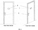
- Figures 1 and 2 show an embodiment that now develops the concept of non-integrated Smart door, consisting of providing access doors with the electronics needed (based on the controlled magnetic field technologies plus additional electronics) in order that said door be able to detect by itself the presence of people in its vicinity and make photographs of such persons (in a preventive manner, i.e. when they are still outside of the house) when they are within a proximity radius predefined by the user.
- This electronics will be additional elements to the door.
- the product is constituted as a whole by the following (see FIG. 1 and FIG. 2 ):
- the peephole and display can be used independently to the sensor, so that the device can display images or video of what is happening on the other side of the door where the system is installed.
- the device is equipped with a LCD display and a button that will turn on and off the system.
- the controlled magnetic field sensor measures at a measurement frequency preset by the user and when it detects the presence of a person, it sends a presence alert together with the images taken by the camera. Both the number of images obtained and the detection thresholds may be programmable by the user.
- the sensor will be equipped with a communications circuit, which can be wired or wireless, that will be used as a means for sending alerts and images to a central system, that may be a physical device or the cloud for later viewing and control from a mobile terminal (phone or Tablet) or a personal computer.
- a communications circuit which can be wired or wireless, that will be used as a means for sending alerts and images to a central system, that may be a physical device or the cloud for later viewing and control from a mobile terminal (phone or Tablet) or a personal computer.
- the functionality of the system is the same as in the previous case with the difference that all the elements would be integrated in the door itself, without installation work by the user, and the sensor would be electrically connected to the metal part of the door, which in this case would act as electrode of the single antenna through which it could be measured the disturbances.
- the system could be powered by rechargeable batteries or directly power supply, depending on the model and customer.
- the operation would be the same as in the previous case, being able to view picture or video on the display after the prior activation by button and detecting system the presence of persons and alerting through attached alarms and images and alarms.
- non-integrated smart window ( FIG. 4 ) consists of the same concept as the door, but without the display. Therefore, it consists of providing windows with the electronics necessary for the detection of human presence in the vicinity of the same, through controlled magnetic field sensors and a camera that can take photographs or video when the sensor detects presence and goes into mode alert.
- the product is constituted as a whole by the following:
- the controlled magnetic field sensor measures at a measurement frequency preset by the user and when it detects the presence of a person, it sends a presence alert together with the images taken by the camera. Both the number of images obtained and the detection thresholds may be programmable by the user.
- the sensor will be equipped with a communications circuit, which can be wired or wireless, that will be used as a means for sending alerts and images to a central system, that may be a physical device or the cloud for later viewing and control from a mobile terminal (phone or Tablet) or a personal computer.
- a communications circuit which can be wired or wireless, that will be used as a means for sending alerts and images to a central system, that may be a physical device or the cloud for later viewing and control from a mobile terminal (phone or Tablet) or a personal computer.
- the functionality of the system is the same as in the case of the non-integrated window ( FIG. 4 ) with the difference that all the elements would be integrated in the window itself, without installation work by the user. Therefore, the metal parts of the window are the ones which are electrically connected to the sensor, constituting the antenna's own electrode, through which the sensor measures disturbances.
- the system could be powered by rechargeable batteries or directly power supply, depending on the model and customer. The operation would be the same as in the previous case.
- the concept of "Smart Wall” is developed with the integrated and non-integrated versions, as in previous cases.
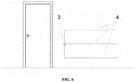
- the solution consists of incorporating into the wall an electronics with controlled magnetic field sensors, and one or more electrodes (although each electrode is a transmitting-receiving antenna) installed by way of adhesive tape ( FIG. 6 ) so as to create a detection area on the external side of the wall with a radius of around 1 m (the part oriented toward the interior of the wall will be shielded).
- adhesive tape FIG. 6
- the product is constituted as a whole by the following (see FIG. 6 ):
- the controlled magnetic field sensor (3) measures at a measurement frequency preset by the user and when it detects the presence of a person, it sends a presence alert.
- the sensor will be equipped with a communications circuit, which can be wired or wireless, that will be used as a means for sending alerts and images to a central system, that may be a physical device or the cloud for later viewing and control from a mobile terminal (phone or Tablet) or a personal computer.
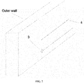
- the concept of "Smart Outer Wall” is developed with the integrated and non-integrated versions, as in previous cases.
- the solution consists of incorporating into the wall an electronics with controlled magnetic field sensors, and one or more electrodes so as to create a detection area on the internal and external sides of the wall with a radius of around 1 m.
- the sensor is able to detect human presence in the vicinity of the wall, reducing the possibility of intrusion or sabotage attempt.
- the product is constituted as a whole by the following (see FIG. 7 ):
- the controlled magnetic field sensor (3) measures at a measurement frequency preset by the user and when it detects the presence of a person, it sends a presence alert.
- the sensor will be equipped with a communications circuit, which can be wired or wireless, that will be used as a means for sending alerts and images to a central system, that may be a physical device or the cloud for later viewing and control from a mobile terminal (phone or Tablet) or a personal computer.
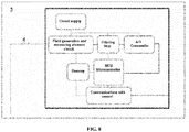
- the controlled magnetic field sensor is one as described in the document PCT/ES2013/070719 .
- FIG. 8 describes an alternative embodiment to said sensor.
- the magnetic field sensor comprises an antenna (4) consisting of a single electrode which at the same is transmitter and receiver (transmitting-receiving electrode) and it is the antenna (4) used in all and each one of the above embodiments, although in some cases it is connected with the metal parts of the door or window (embodiments in FIGs. 3 , 5 and 6 ). It must be taken into account that in some embodiments, several antennas can coexist in parallel, even though each of them retains the particularity of being transmitter and receiver at the same time.
- the controlled magnetic field sensor also comprises a field generation and measurement circuit, preferably a tuner circuit with operating frequency less than 5 MHz comprising an RLC circuit and a phase-stabilizing circuit.
- the signal received at the antenna passes by a filtering stage and, subsequently, said signal pass to an analog-digital converter, which in turn is connected to a processor configured to detect the variations in the magnetic field, establishing a kind of three-dimensional map with such variations, being able to determine the volume and density of the object that said variation has generated.
- This processor is connected to a radio frequency circuit which emits a signal encrypted towards a switchboard or external integrated surveillance system, which controls the entire installation.
- the circuit is completed by a data storage memory.
Landscapes
- Engineering & Computer Science (AREA)
- Life Sciences & Earth Sciences (AREA)
- Physics & Mathematics (AREA)
- Remote Sensing (AREA)
- General Physics & Mathematics (AREA)
- Environmental & Geological Engineering (AREA)
- Geology (AREA)
- General Life Sciences & Earth Sciences (AREA)
- Electromagnetism (AREA)
- Geophysics (AREA)
- Civil Engineering (AREA)
- Structural Engineering (AREA)
- Burglar Alarm Systems (AREA)
- Alarm Systems (AREA)
- Closed-Circuit Television Systems (AREA)
- Emergency Alarm Devices (AREA)
- Geophysics And Detection Of Objects (AREA)
Description
- The object of the invention is a home security system. The invention has its practical application in the security sector, and more specifically in private or domestic security in properties, being its main aim an intrusion detection through a door, window, or fence, although it can be used in other locations such as walls or wall.
- Currently, in the field of private security for indoor spaces, different types of devices capable of detecting an intrusion into a home or similar are used. Among the different types of detection devices are the following:
- a) Volumetric sensors, which detect changes in the volume of the measuring area and translate them into motion detection.
- b) Door-opening Sensors that detect when a door or window is opened or closed.
- c) Infrared barrier sensors that detect the passage of an object between their transmitters and receivers.
- d) Vibration or glass break sensor that detect vibration in crystals when they are beaten or suffer a break.
- All these devices have in common that are installed inside a house. Therefore, they do not offer a preventive security, since they are only capable of detecting an intrusion when this has already happened. Therefore, it is not a preventive security system, but an event warning or alarm system. On the other hand, both volumetric sensors and infrared barrier sensors are unable to, in addition, discriminate the types of moving objects or the different movements that occur within its range.
- To avoid these problems, the best solution is the electrostatic field sensors. However, most of the documents are based on uncontrolled signals and on the indirect measure of capacity depending on the variation in the resonance frequency of the signal and/or in its impedance.
- For example, the document
ES 2152335 T3 - Thanks to this detector device, it is achieved a security system in a first presence area indicating that the intruder has approached the protected object at a distance of between 100 and 150 cm; a second presence area which indicates that the intruder has approached the object protected at a distance of 30 cm; and a third presence area which indicates that the intruder almost makes contact with the protected object.
- Therefore, this invention creates a square wave, wherein depending on the variation of the frequency of the same the related capacity can be calculated. This signal creates a magnetic field in the conductor which is out of control, i.e., its field lines extend in all directions and, in addition, undergoes variations with the temperature, humidity and other conditions, so it needs to correct these problems.
- In general, none of the documents in the State of the art describes a system capable of measuring the disturbance in a single antenna and, thereafter, inferring the presence of a person, distinguishing it from animal or thing through the measurement of the disturbance itself on the single antenna. This disturbance detection also involves a change in the topology of circuits used against the solutions with transmitter and receiver solutions (as in documents
US2004090234 andUS5914610 ). - The document
US2014267716 discloses a system including a control panel configured to communicate with at least one mobile wireless device, including sending image data to the at least one mobile wireless device using electronic messaging protocols. The system also includes at least one automation component wirelessly connected to the control panel through short range wireless communication protocols. The at least one automation component includes at least one sensor configured to detect a presence of a person at an entry to the physical structure, at least one camera inconspicuously integrated within an entry component at the entry, and at least one short range wireless transceiver coupled to the at least one sensor and the at least one camera and configured to communicate image and sensor data to the control panel and to receive control information from the control panel. - Otherwise, the document
US6329913 discloses a passenger detection system. The passenger detection system utilizes an oscillation circuit that causes an antenna electrode to emit an electric field that is disrupted by the electrical characteristics of an object placed on the seat. This disruption alters the current and phase of the signal in the antenna electrode. By comparing the current flowing in the antenna electrode and/or the difference between the phase of the signal in the antenna electrode and the oscillation circuit output signal with predetermined threshold values, it is possible to detect the presence of a passenger in a reliable and inexpensive manner. - Otherwise, the document
US3862895 describes an electrode type sensing device which employs two separated measuring electrodes of the same type and a common ground for making electrode potential determinations such as dissolved oxygen and pH measurement in a liquid. In one embodiment, one of the measuring electrodes is disposed in a standard solution which is placed in but sealed from the material to be tested except for an electrical communication. In an alternative embodiment, both measuring electrodes are placed in a material wherein the ion or molecular content of which is to be measured but, at a substantial distance from each other and with a common ground. Both embodiments eliminate the previous problem of temperature and other environmental aspects which affect a reference electrode and the measuring electrode in a different manner. Finally it is also known documentsUS5764145 ,US4325058 ,US2004085450 ,DE102013011258 ,WO94246545 CN203827455 . - However, none of the cited documents disclose a controlled magnetic field sensor connected to an antenna that consist of a single electrode which at the same time is transmitter and receiver in such a way that the sensor carries out a continuous measurement of the capacity that mould the field generated on the antenna and allows that a processor connected to the sensor determines the volume and density of material which generates a fluctuation of the field on the antenna.
- The object of this invention is a home security system according to
claim 1. - The invention is based on the capacity of sensor object of the invention to measure the variations in the magnetic field existing around a single conducting element, in the case of the invention a coaxial cable, which acts as a probe or antenna, when said field is affected by the influence of a charged body, such as the human body.
- The human body, like any other existing object, has its own electrical characteristics, dependent on the materials, density, volume, temperature and conductivity. The differences in the potential between the different objects result in electrostatic interactions from an object to another when they come into contact or are close to each other. This effect is used by the sensor object of the invention, achieving the continuous measurement of fluctuations that said field causes in an electronic circuit connected to it. This circuit, through the changes in the field magnitude is able to distinguish different types of bodies or objects and to discriminate the human presence from another material or animal presence. Indeed, in carrying out the continuous measurement of the magnetic field it moulds the magnetic field generated on the antenna and through infinite field lines, a processor connected to the same allows determining the volume and density of material which generates the field fluctuation on the antenna.
- The invention is applied to security systems in homes, giving the capacity to detect intrusions proactively in doors, windows and fences or walls, i.e. the detection capability before the intrusion takes place.
- Throughout the description and claims, the word "comprises" and its variations are not intended to exclude other technical features, additives, components or steps. For those skilled in the art, other objects, advantages and characteristics of the invention will emerge in part from the description and in part from the practice of the invention. The following examples and drawings are provided by way of illustration, and are not intended to be limiting of the present invention. The following examples and drawings are provided by way of illustration, and are not intended to be limiting of the present invention. Furthermore, the present invention covers all the possible combinations of particular and preferred embodiments herein indicated.
- There follows a very brief description of a series of drawings that help to provide a better understanding of the invention and which are associated expressly with an embodiment of said invention that is presented as a non-limiting example thereof.
-
FIG. 1 - General scheme of a door with the non-integrated security system. -
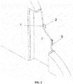
FIG. 2 - Schematic detail of the door inFIG. 1 . -
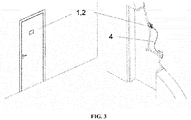
FIG. 3 - General scheme of a door with the integrated security system. -
FIG. 4 - General scheme of a window with the non-integrated security system. -
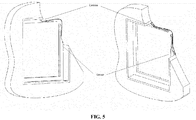
FIG. 5 - General scheme of a window with the integrated general system. -
FIG. 6 - General scheme of an inner enclosure with the integrated system. -
FIG. 7 - General scheme of an outer enclosure with the non-integrated system. -
FIG. 8 - Block diagram of a sensor according to the invention. - An object of the invention is a home security system comprising interchangeably, a door, a window, a wall or any of the above in combination. Below it is detailed each of the particular embodiments of the parts that make up the system object of the invention.
-
Figures 1 and2 show an embodiment that now develops the concept of non-integrated Smart door, consisting of providing access doors with the electronics needed (based on the controlled magnetic field technologies plus additional electronics) in order that said door be able to detect by itself the presence of people in its vicinity and make photographs of such persons (in a preventive manner, i.e. when they are still outside of the house) when they are within a proximity radius predefined by the user. This electronics will be additional elements to the door. - The product is constituted as a whole by the following (see
FIG. 1 andFIG. 2 ): - Electronic peephole with integrated camera (1). The camera may be of high or low resolution depending on the model, and may have an optics with apertures between 60 and 140 degrees, depending on model. This peephole may include in a top model, a microphone for audio capture.
- LCD display (2) for real-time image visualization. This circuit will include wired or wireless communications circuit to communicate with the sensor. The screen may be LCD or LED, with touch interface or not, depending on model. This display, in top models, may have speakers to reproduce sounds coming from the microphone set out in the preceding paragraph.
- Controlled magnetic field sensor (3) as described in
PCT/ES2014/070719 - Both elements, sensor and electronic peephole plus display, would be powered by rechargeable batteries.
- On the one hand, the peephole and display can be used independently to the sensor, so that the device can display images or video of what is happening on the other side of the door where the system is installed. To do this, the device is equipped with a LCD display and a button that will turn on and off the system.
- On the other hand, there is a combined functionality Sensor - Peephole in which the controlled magnetic field sensor measures at a measurement frequency preset by the user and when it detects the presence of a person, it sends a presence alert together with the images taken by the camera. Both the number of images obtained and the detection thresholds may be programmable by the user.
- The sensor will be equipped with a communications circuit, which can be wired or wireless, that will be used as a means for sending alerts and images to a central system, that may be a physical device or the cloud for later viewing and control from a mobile terminal (phone or Tablet) or a personal computer.
- In the case of integrated smart door, as shown in
FIG. 3 , the functionality of the system is the same as in the previous case with the difference that all the elements would be integrated in the door itself, without installation work by the user, and the sensor would be electrically connected to the metal part of the door, which in this case would act as electrode of the single antenna through which it could be measured the disturbances. In this case, the system could be powered by rechargeable batteries or directly power supply, depending on the model and customer. - The operation would be the same as in the previous case, being able to view picture or video on the display after the prior activation by button and detecting system the presence of persons and alerting through attached alarms and images and alarms.
- The concept of non-integrated smart window (
FIG. 4 ) consists of the same concept as the door, but without the display. Therefore, it consists of providing windows with the electronics necessary for the detection of human presence in the vicinity of the same, through controlled magnetic field sensors and a camera that can take photographs or video when the sensor detects presence and goes into mode alert. - The product is constituted as a whole by the following:
- Camera which may be of high or low resolution depending on the model, and may have an optics with apertures between 60 and 140 degrees, depending on model.
- Controlled magnetic field sensor in accordance with
PCT/ES2014/070719 - Both elements, sensor and camera, will be powered by rechargeable batteries.
- The controlled magnetic field sensor measures at a measurement frequency preset by the user and when it detects the presence of a person, it sends a presence alert together with the images taken by the camera. Both the number of images obtained and the detection thresholds may be programmable by the user.
- The sensor will be equipped with a communications circuit, which can be wired or wireless, that will be used as a means for sending alerts and images to a central system, that may be a physical device or the cloud for later viewing and control from a mobile terminal (phone or Tablet) or a personal computer.
- In the case of the integrated smart window (
FIG. 5 ), the functionality of the system is the same as in the case of the non-integrated window (FIG. 4 ) with the difference that all the elements would be integrated in the window itself, without installation work by the user. Therefore, the metal parts of the window are the ones which are electrically connected to the sensor, constituting the antenna's own electrode, through which the sensor measures disturbances. In this case, the system could be powered by rechargeable batteries or directly power supply, depending on the model and customer. The operation would be the same as in the previous case. - For external perimeter solutions, the concept of "Smart Wall" is developed with the integrated and non-integrated versions, as in previous cases. In this case, the solution consists of incorporating into the wall an electronics with controlled magnetic field sensors, and one or more electrodes (although each electrode is a transmitting-receiving antenna) installed by way of adhesive tape (
FIG. 6 ) so as to create a detection area on the external side of the wall with a radius of around 1 m (the part oriented toward the interior of the wall will be shielded). In this way, the sensor is able to detect human presence in the vicinity of the wall, reducing the possibility of theft through hole-in-wall technique, or similar. - The product is constituted as a whole by the following (see
FIG. 6 ): - Controlled magnetic field sensor, located on the wall surface. This circuit will include wired or wireless communications circuit to communicate with the central system. The sensor may include a personal identification circuit to identify users and inhibit the alarms when necessary.
- Electrode(s) made of adhesive material with a maximum length of 10 metres that serves as a magnetic field generation and measuring element. The electrode will be constructed on flexible and adhesive substrate and will be composed of metal alloys.
- It is powered by rechargeable batteries or power supply.
- The controlled magnetic field sensor (3) measures at a measurement frequency preset by the user and when it detects the presence of a person, it sends a presence alert. The sensor will be equipped with a communications circuit, which can be wired or wireless, that will be used as a means for sending alerts and images to a central system, that may be a physical device or the cloud for later viewing and control from a mobile terminal (phone or Tablet) or a personal computer.
- For external perimeter solutions, the concept of "Smart Outer Wall" is developed with the integrated and non-integrated versions, as in previous cases. In this case, the solution consists of incorporating into the wall an electronics with controlled magnetic field sensors, and one or more electrodes so as to create a detection area on the internal and external sides of the wall with a radius of around 1 m. In this way, the sensor is able to detect human presence in the vicinity of the wall, reducing the possibility of intrusion or sabotage attempt.
- The product is constituted as a whole by the following (see
FIG. 7 ): - Controlled magnetic field sensor, located on the wall surface. This circuit will include wired or wireless communications circuit to communicate with the central system. The sensor may include a personal identification circuit to identify users and inhibit the alarms when necessary.
- Electrode(s) with a maximum length of 10 metres that serves as a magnetic field generation and measuring element.
- The elements will be powered by rechargeable batteries or power supply.
- The controlled magnetic field sensor (3) measures at a measurement frequency preset by the user and when it detects the presence of a person, it sends a presence alert. The sensor will be equipped with a communications circuit, which can be wired or wireless, that will be used as a means for sending alerts and images to a central system, that may be a physical device or the cloud for later viewing and control from a mobile terminal (phone or Tablet) or a personal computer.
- The controlled magnetic field sensor is one as described in the document
PCT/ES2013/070719 FIG. 8 describes an alternative embodiment to said sensor. As can be seen in saidFIG. 8 , the magnetic field sensor comprises an antenna (4) consisting of a single electrode which at the same is transmitter and receiver (transmitting-receiving electrode) and it is the antenna (4) used in all and each one of the above embodiments, although in some cases it is connected with the metal parts of the door or window (embodiments inFIGs. 3 ,5 and6 ). It must be taken into account that in some embodiments, several antennas can coexist in parallel, even though each of them retains the particularity of being transmitter and receiver at the same time. - However, the controlled magnetic field sensor also comprises a field generation and measurement circuit, preferably a tuner circuit with operating frequency less than 5 MHz comprising an RLC circuit and a phase-stabilizing circuit. The signal received at the antenna, after the measurement, passes by a filtering stage and, subsequently, said signal pass to an analog-digital converter, which in turn is connected to a processor configured to detect the variations in the magnetic field, establishing a kind of three-dimensional map with such variations, being able to determine the volume and density of the object that said variation has generated. This processor, in turn, is connected to a radio frequency circuit which emits a signal encrypted towards a switchboard or external integrated surveillance system, which controls the entire installation. The circuit is completed by a data storage memory.
Claims (15)
- A home security system connected to an external integrated surveillance system, wherein said home security system is installed in at least a door, a window or an architectural enclosure;
wherein the system comprises, at least, a controlled magnetic field sensor (3) connected to an antenna (4) wherein the antenna (4) consists of a single electrode which at the same time is transmitter and receiver of a magnetic field; and
wherein the magnetic field is redirected in a controlled manner through the shielding of an unwanted emission area to focus the magnetic field on a certain area;
characterized in that
the controlled magnetic field sensor (3) comprises a processor configured to:measure continuously the magnetic field around the antenna (4);detect a disturbance in the magnetic field around the antenna (4) through the continuous measurement of the changes in the magnetic field magnitude at a operating frequency pre-set by a user; andestablish if there is a presence of a person depending on the power of the disturbance detected. - The system of claim 1 comprising a door including:an electronic peephole with integrated camera (1);a display (2); andthe controlled magnetic field sensor (3) connected to the antenna (4); andwherein the controlled magnetic field sensor (3) is configured to detect a disturbance in a magnetic field detected by its antenna (4) and establish if there is a presence of a person depending on the power of the disturbance; and send an alert for the presence of a person together with the images taken by the camera (1).
- The system of claim 2, where the antenna (4) is electrically connected to at least a metal part that integrates the door.
- The system of any of claims 2-3 comprising an inclinometer.
- The system of any of claims 2-3 comprising an accelerometer.
- The system of claim 1 comprising a window comprising an integrated camera (1) and the controlled magnetic field sensor (3) connected to the antenna (4) wherein the controlled magnetic field sensor (3) is configured to detect a disturbance in the magnetic field detected by its antenna (4) and establish if there is a presence of a person depending on the power of the disturbance; and send an alert for the presence of a person together with the images taken by the camera (1).
- The system of claim 6 where the antenna is electrically connected to at least a metal part that integrates the window.
- The system of any of claims 6-7 comprising an inclinometer.
- The system of any of claims 6-8 comprising an accelerometer.
- The system of claim 1 wherein the architectural enclosure comprises the controlled magnetic field sensor (3) connected to the antenna (4) and where the controlled magnetic field sensor (3) is configured to detect a disturbance in the magnetic field detected by the antenna (4) and establish if there is a presence of a person depending on the power of the disturbance; and send an alert for the presence of a person; and wherein the electrode is made of adhesive material and has a maximum length of ten meters configured as a magnetic field generation and measuring element connected to the controlled magnetic field sensor (3); and where the electrode will be constructed on flexible and adhesive substrate and will be composed of metal alloys.
- The system of claim 10, where the electrode is integrated inside the system.
- The system of any of claims 10-11 that is an outer enclosure.
- The system of any of claims 10-11 that is an inner enclosure.
- A home security method implemented in a system according to any of claims 1-13 connected to an external integrated surveillance system, wherein said home security system is installed in at least a door, a window or an architectural enclosure; the method comprising the steps of:
providing an antenna (4) which consists of a single electrode which at the same time is transmitter and receiver of a magnetic field generated around the antenna (4) wherein:the magnetic field is generated and measured by a controlled magnetic field sensor (3);and the magnetic field is redirected in a controlled manner through the shielding of an unwanted emission area to focus the magnetic field on a certain area;characterized in that the method further comprises the steps of:measuring continuously the magnetic field around the antenna (4);detecting a disturbance in the magnetic field around the antenna (4) through the continuous measurement of the changes in the magnetic field magnitude at a operating frequency pre-set by a user; andestablishing if there is a presence of a person depending on the power of the detected disturbance; andsending an alert to the external integrated surveillance system including at least the presence of the person established in the previous step. - The method of claim 14 wherein the alert to the external integrated surveillance system further includes at least one image taken by a camera (1).
Priority Applications (13)
| Application Number | Priority Date | Filing Date | Title |
|---|---|---|---|
| DK15162297.4T DK3076206T3 (en) | 2015-04-01 | 2015-04-01 | HOME SECURITY SYSTEM |
| ES15162297T ES2714688T3 (en) | 2015-04-01 | 2015-04-01 | Home security system |
| PL15162297T PL3076206T3 (en) | 2015-04-01 | 2015-04-01 | Home security system |
| EP15162297.4A EP3076206B1 (en) | 2015-04-01 | 2015-04-01 | Home security system |
| HUE15162297A HUE044100T2 (en) | 2015-04-01 | 2015-04-01 | Home security system |
| PT15162297T PT3076206T (en) | 2015-04-01 | 2015-04-01 | Home security system |
| PCT/ES2016/070225 WO2016156654A1 (en) | 2015-04-01 | 2016-04-01 | Domestic security system |
| CA2984467A CA2984467C (en) | 2015-04-01 | 2016-04-01 | Home security system |
| AU2016239558A AU2016239558B2 (en) | 2015-04-01 | 2016-04-01 | Domestic security system |
| CN201680027320.3A CN107849896B (en) | 2015-04-01 | 2016-04-01 | Household safety system |
| RU2017137939A RU2691934C2 (en) | 2015-04-01 | 2016-04-01 | Home security system |
| US15/563,452 US10754054B2 (en) | 2015-04-01 | 2016-04-01 | Domestic security system |
| JP2017551670A JP6693970B2 (en) | 2015-04-01 | 2016-04-01 | Home security system |
Applications Claiming Priority (1)
| Application Number | Priority Date | Filing Date | Title |
|---|---|---|---|
| EP15162297.4A EP3076206B1 (en) | 2015-04-01 | 2015-04-01 | Home security system |
Publications (2)
| Publication Number | Publication Date |
|---|---|
| EP3076206A1 EP3076206A1 (en) | 2016-10-05 |
| EP3076206B1 true EP3076206B1 (en) | 2018-12-05 |
Family
ID=53267203
Family Applications (1)
| Application Number | Title | Priority Date | Filing Date |
|---|---|---|---|
| EP15162297.4A Active EP3076206B1 (en) | 2015-04-01 | 2015-04-01 | Home security system |
Country Status (13)
| Country | Link |
|---|---|
| US (1) | US10754054B2 (en) |
| EP (1) | EP3076206B1 (en) |
| JP (1) | JP6693970B2 (en) |
| CN (1) | CN107849896B (en) |
| AU (1) | AU2016239558B2 (en) |
| CA (1) | CA2984467C (en) |
| DK (1) | DK3076206T3 (en) |
| ES (1) | ES2714688T3 (en) |
| HU (1) | HUE044100T2 (en) |
| PL (1) | PL3076206T3 (en) |
| PT (1) | PT3076206T (en) |
| RU (1) | RU2691934C2 (en) |
| WO (1) | WO2016156654A1 (en) |
Families Citing this family (9)
| Publication number | Priority date | Publication date | Assignee | Title |
|---|---|---|---|---|
| US11064168B1 (en) * | 2017-09-29 | 2021-07-13 | Objectvideo Labs, Llc | Video monitoring by peep hole device |
| PL3553477T3 (en) * | 2018-04-13 | 2021-05-17 | Ontech Security, S.L. | Disturbance measurement apparatus in a controlled magnetic field |
| CN109544402A (en) * | 2018-11-28 | 2019-03-29 | 浙江理工大学 | A kind of anti-escape ticket method in scenic spot based on capacitance sensor and system |
| CN111435465A (en) * | 2018-12-25 | 2020-07-21 | 中国科学院深圳先进技术研究院 | House window detection method, device and system |
| CN109819218A (en) * | 2019-02-25 | 2019-05-28 | 苏州小点智能家居有限公司 | A kind of safety device for smart home |
| DE102019105600A1 (en) * | 2019-03-06 | 2020-09-10 | Dr. Ing. H.C. F. Porsche Aktiengesellschaft | Motor vehicle |
| CN113376701A (en) * | 2021-05-20 | 2021-09-10 | 深圳曦华科技有限公司 | Antenna module, temperature change detection method and device and related application |
| EP4213121A1 (en) | 2022-01-17 | 2023-07-19 | Ontech Security, SL | Method and device to measure disruptions in a controlled electromagnetic field |
| EP4212890A1 (en) | 2022-01-17 | 2023-07-19 | Ontech Security, SL | Method and device to measure disruptions in a controlled electromagnetic field |
Family Cites Families (23)
| Publication number | Priority date | Publication date | Assignee | Title |
|---|---|---|---|---|
| US3862895A (en) * | 1970-06-05 | 1975-01-28 | Great Lakes Instruments Inc | Self-compensating electrode system |
| US4325058A (en) * | 1980-06-11 | 1982-04-13 | Gentex Corporation | Pre-intrusion detection and alarm system |
| JP2917559B2 (en) * | 1991-04-12 | 1999-07-12 | 松下電器産業株式会社 | Integrally formed structures such as windows, sliding doors, foreheads, etc. and their manufacturing methods |
| SE9301206L (en) * | 1993-04-08 | 1994-10-09 | Goeran Hansson | Monitoring method and device at glass pane |
| SE9303582D0 (en) * | 1993-10-29 | 1993-10-29 | Goeran Hansson | Touch and theft protection for office equipment |
| US5914610A (en) | 1994-02-03 | 1999-06-22 | Massachusetts Institute Of Technology | Apparatus and method for characterizing movement of a mass within a defined space |
| JP3990017B2 (en) * | 1998-01-30 | 2007-10-10 | 株式会社日立アドバンストデジタル | Camera integrated display |
| US6329913B1 (en) * | 1999-10-05 | 2001-12-11 | Nec Technologies, Inc. | Passenger detection system and method |
| CA2445444C (en) * | 2001-04-26 | 2006-10-24 | Litens Automotive | Powered liftgate opening mechanism and control system |
| US7012523B2 (en) * | 2002-11-05 | 2006-03-14 | Stuart John C | System for surveillance of and communication with residential entryway from remote location using existing telephone lines |
| US6777940B2 (en) | 2002-11-08 | 2004-08-17 | Ultima Labs, Inc. | Apparatus and method for resistivity well logging |
| CN100390549C (en) * | 2003-10-15 | 2008-05-28 | 财团法人工业技术研究院 | Electromagnetic field sensing element and its apparatus |
| RU66086U1 (en) * | 2006-10-24 | 2007-08-27 | Олег Борисович Кудрявцев | DEVICE FOR DETECTING A CONNECTED ACCESS THROUGH A DOOR OPENING OF SEVERAL PERSONS |
| WO2009058543A1 (en) * | 2007-10-10 | 2009-05-07 | Kovio, Inc. | High reliability surveillance and/or identification tag/devices and methods of making and using the same |
| US8733448B2 (en) * | 2010-03-25 | 2014-05-27 | Halliburton Energy Services, Inc. | Electrically operated isolation valve |
| FR2959019B1 (en) * | 2010-04-14 | 2012-06-08 | Commissariat Energie Atomique | METHOD AND DEVICE FOR COMPENSATING A MEASUREMENT OF A MAGNETIC FIELD, METHOD AND SYSTEM FOR LOCATING AN OBJECT, RECORDING MEDIUM FOR THESE METHODS |
| JP5625723B2 (en) * | 2010-10-15 | 2014-11-19 | ソニー株式会社 | Electronic device, power supply method and power supply system |
| KR20120063987A (en) * | 2010-12-08 | 2012-06-18 | 고현빈 | Digital window |
| US10999561B2 (en) * | 2013-03-15 | 2021-05-04 | Vivint, Inc. | Methods for using an image capture device integrated at a building entry with an automation control panel, and systems and devices related thereto |
| DE102013011258A1 (en) * | 2013-07-05 | 2015-01-08 | Schneider Schreibgeräte GmbH | Device for determining the position of objects or persons |
| CN103422771A (en) * | 2013-07-30 | 2013-12-04 | 南昌大学 | Home security intelligent window |
| CN203827455U (en) * | 2014-01-06 | 2014-09-10 | 重庆宝捷迅科技有限公司 | Electronic peephole having videoing function |
| US20160247027A1 (en) * | 2015-02-24 | 2016-08-25 | Alphan Tsoi | Electronic door peephole system and monitoring method thereof |
-
2015
- 2015-04-01 PL PL15162297T patent/PL3076206T3/en unknown
- 2015-04-01 HU HUE15162297A patent/HUE044100T2/en unknown
- 2015-04-01 PT PT15162297T patent/PT3076206T/en unknown
- 2015-04-01 ES ES15162297T patent/ES2714688T3/en active Active
- 2015-04-01 EP EP15162297.4A patent/EP3076206B1/en active Active
- 2015-04-01 DK DK15162297.4T patent/DK3076206T3/en active
-
2016
- 2016-04-01 US US15/563,452 patent/US10754054B2/en active Active
- 2016-04-01 CN CN201680027320.3A patent/CN107849896B/en active Active
- 2016-04-01 RU RU2017137939A patent/RU2691934C2/en active
- 2016-04-01 WO PCT/ES2016/070225 patent/WO2016156654A1/en active Application Filing
- 2016-04-01 AU AU2016239558A patent/AU2016239558B2/en not_active Ceased
- 2016-04-01 CA CA2984467A patent/CA2984467C/en active Active
- 2016-04-01 JP JP2017551670A patent/JP6693970B2/en active Active
Non-Patent Citations (1)
| Title |
|---|
| None * |
Also Published As
| Publication number | Publication date |
|---|---|
| ES2714688T3 (en) | 2019-05-29 |
| PL3076206T3 (en) | 2019-06-28 |
| CN107849896A (en) | 2018-03-27 |
| EP3076206A1 (en) | 2016-10-05 |
| WO2016156654A1 (en) | 2016-10-06 |
| JP6693970B2 (en) | 2020-05-13 |
| RU2017137939A (en) | 2019-05-06 |
| AU2016239558A1 (en) | 2017-11-23 |
| JP2018519559A (en) | 2018-07-19 |
| AU2016239558B2 (en) | 2021-05-27 |
| US20180120466A1 (en) | 2018-05-03 |
| DK3076206T3 (en) | 2019-03-25 |
| US10754054B2 (en) | 2020-08-25 |
| CA2984467C (en) | 2023-08-22 |
| PT3076206T (en) | 2019-03-14 |
| CN107849896B (en) | 2020-02-21 |
| RU2017137939A3 (en) | 2019-05-24 |
| HUE044100T2 (en) | 2019-09-30 |
| RU2691934C2 (en) | 2019-06-18 |
| CA2984467A1 (en) | 2016-10-06 |
Similar Documents
| Publication | Publication Date | Title |
|---|---|---|
| EP3076206B1 (en) | Home security system | |
| US11067713B2 (en) | Electrostatic field sensor and security system in interior and exterior spaces | |
| US10497230B2 (en) | Smart barrier alarm device | |
| KR101796247B1 (en) | Intelligent IoT device and system for detection of door state based on context-awareness | |
| US20060002461A1 (en) | External perimeter monitoring system | |
| JP2018519559A5 (en) | ||
| CN108475458A (en) | Window sensor device with mobile detection | |
| US20050122223A1 (en) | Detection of bodies | |
| KR20160114491A (en) | Real-time security alarm system using the ultrasonic sensors and CVD Capacitive Touch Sensors |
Legal Events
| Date | Code | Title | Description |
|---|---|---|---|
| PUAI | Public reference made under article 153(3) epc to a published international application that has entered the european phase |
Free format text: ORIGINAL CODE: 0009012 |
|
| 17P | Request for examination filed |
Effective date: 20160314 |
|
| AK | Designated contracting states |
Kind code of ref document: A1 Designated state(s): AL AT BE BG CH CY CZ DE DK EE ES FI FR GB GR HR HU IE IS IT LI LT LU LV MC MK MT NL NO PL PT RO RS SE SI SK SM TR |
|
| STAA | Information on the status of an ep patent application or granted ep patent |
Free format text: STATUS: EXAMINATION IS IN PROGRESS |
|
| 17Q | First examination report despatched |
Effective date: 20170413 |
|
| GRAP | Despatch of communication of intention to grant a patent |
Free format text: ORIGINAL CODE: EPIDOSNIGR1 |
|
| STAA | Information on the status of an ep patent application or granted ep patent |
Free format text: STATUS: GRANT OF PATENT IS INTENDED |
|
| INTG | Intention to grant announced |
Effective date: 20180629 |
|
| GRAS | Grant fee paid |
Free format text: ORIGINAL CODE: EPIDOSNIGR3 |
|
| GRAA | (expected) grant |
Free format text: ORIGINAL CODE: 0009210 |
|
| GRAA | (expected) grant |
Free format text: ORIGINAL CODE: 0009210 |
|
| STAA | Information on the status of an ep patent application or granted ep patent |
Free format text: STATUS: THE PATENT HAS BEEN GRANTED |
|
| AK | Designated contracting states |
Kind code of ref document: B1 Designated state(s): AL AT BE BG CH CY CZ DE DK EE ES FI FR GB GR HR HU IE IS IT LI LT LU LV MC MK MT NL NO PL PT RO RS SE SI SK SM TR |
|
| REG | Reference to a national code |
Ref country code: GB Ref legal event code: FG4D |
|
| REG | Reference to a national code |
Ref country code: CH Ref legal event code: EP |
|
| REG | Reference to a national code |
Ref country code: AT Ref legal event code: REF Ref document number: 1073770 Country of ref document: AT Kind code of ref document: T Effective date: 20181215 |
|
| REG | Reference to a national code |
Ref country code: IE Ref legal event code: FG4D |
|
| REG | Reference to a national code |
Ref country code: DE Ref legal event code: R096 Ref document number: 602015020704 Country of ref document: DE |
|
| REG | Reference to a national code |
Ref country code: CH Ref legal event code: NV Representative=s name: TR-IP CONSULTING LLC, CH |
|
| REG | Reference to a national code |
Ref country code: PT Ref legal event code: SC4A Ref document number: 3076206 Country of ref document: PT Date of ref document: 20190314 Kind code of ref document: T Free format text: AVAILABILITY OF NATIONAL TRANSLATION Effective date: 20190227 |
|
| REG | Reference to a national code |
Ref country code: DK Ref legal event code: T3 Effective date: 20190318 |
|
| REG | Reference to a national code |
Ref country code: SE Ref legal event code: TRGR |
|
| REG | Reference to a national code |
Ref country code: NL Ref legal event code: FP |
|
| REG | Reference to a national code |
Ref country code: LT Ref legal event code: MG4D |
|
| PG25 | Lapsed in a contracting state [announced via postgrant information from national office to epo] |
Ref country code: BG Free format text: LAPSE BECAUSE OF FAILURE TO SUBMIT A TRANSLATION OF THE DESCRIPTION OR TO PAY THE FEE WITHIN THE PRESCRIBED TIME-LIMIT Effective date: 20190305 Ref country code: LT Free format text: LAPSE BECAUSE OF FAILURE TO SUBMIT A TRANSLATION OF THE DESCRIPTION OR TO PAY THE FEE WITHIN THE PRESCRIBED TIME-LIMIT Effective date: 20181205 Ref country code: HR Free format text: LAPSE BECAUSE OF FAILURE TO SUBMIT A TRANSLATION OF THE DESCRIPTION OR TO PAY THE FEE WITHIN THE PRESCRIBED TIME-LIMIT Effective date: 20181205 Ref country code: LV Free format text: LAPSE BECAUSE OF FAILURE TO SUBMIT A TRANSLATION OF THE DESCRIPTION OR TO PAY THE FEE WITHIN THE PRESCRIBED TIME-LIMIT Effective date: 20181205 |
|
| REG | Reference to a national code |
Ref country code: NO Ref legal event code: T2 Effective date: 20181205 |
|
| REG | Reference to a national code |
Ref country code: ES Ref legal event code: FG2A Ref document number: 2714688 Country of ref document: ES Kind code of ref document: T3 Effective date: 20190529 |
|
| PG25 | Lapsed in a contracting state [announced via postgrant information from national office to epo] |
Ref country code: AL Free format text: LAPSE BECAUSE OF FAILURE TO SUBMIT A TRANSLATION OF THE DESCRIPTION OR TO PAY THE FEE WITHIN THE PRESCRIBED TIME-LIMIT Effective date: 20181205 Ref country code: RS Free format text: LAPSE BECAUSE OF FAILURE TO SUBMIT A TRANSLATION OF THE DESCRIPTION OR TO PAY THE FEE WITHIN THE PRESCRIBED TIME-LIMIT Effective date: 20181205 |
|
| REG | Reference to a national code |
Ref country code: GR Ref legal event code: EP Ref document number: 20190400642 Country of ref document: GR Effective date: 20190509 |
|
| PG25 | Lapsed in a contracting state [announced via postgrant information from national office to epo] |
Ref country code: CZ Free format text: LAPSE BECAUSE OF FAILURE TO SUBMIT A TRANSLATION OF THE DESCRIPTION OR TO PAY THE FEE WITHIN THE PRESCRIBED TIME-LIMIT Effective date: 20181205 |
|
| PG25 | Lapsed in a contracting state [announced via postgrant information from national office to epo] |
Ref country code: EE Free format text: LAPSE BECAUSE OF FAILURE TO SUBMIT A TRANSLATION OF THE DESCRIPTION OR TO PAY THE FEE WITHIN THE PRESCRIBED TIME-LIMIT Effective date: 20181205 Ref country code: SM Free format text: LAPSE BECAUSE OF FAILURE TO SUBMIT A TRANSLATION OF THE DESCRIPTION OR TO PAY THE FEE WITHIN THE PRESCRIBED TIME-LIMIT Effective date: 20181205 Ref country code: RO Free format text: LAPSE BECAUSE OF FAILURE TO SUBMIT A TRANSLATION OF THE DESCRIPTION OR TO PAY THE FEE WITHIN THE PRESCRIBED TIME-LIMIT Effective date: 20181205 Ref country code: IS Free format text: LAPSE BECAUSE OF FAILURE TO SUBMIT A TRANSLATION OF THE DESCRIPTION OR TO PAY THE FEE WITHIN THE PRESCRIBED TIME-LIMIT Effective date: 20190405 Ref country code: SK Free format text: LAPSE BECAUSE OF FAILURE TO SUBMIT A TRANSLATION OF THE DESCRIPTION OR TO PAY THE FEE WITHIN THE PRESCRIBED TIME-LIMIT Effective date: 20181205 |
|
| REG | Reference to a national code |
Ref country code: DE Ref legal event code: R097 Ref document number: 602015020704 Country of ref document: DE |
|
| REG | Reference to a national code |
Ref country code: HU Ref legal event code: AG4A Ref document number: E044100 Country of ref document: HU |
|
| PLBE | No opposition filed within time limit |
Free format text: ORIGINAL CODE: 0009261 |
|
| STAA | Information on the status of an ep patent application or granted ep patent |
Free format text: STATUS: NO OPPOSITION FILED WITHIN TIME LIMIT |
|
| PG25 | Lapsed in a contracting state [announced via postgrant information from national office to epo] |
Ref country code: SI Free format text: LAPSE BECAUSE OF FAILURE TO SUBMIT A TRANSLATION OF THE DESCRIPTION OR TO PAY THE FEE WITHIN THE PRESCRIBED TIME-LIMIT Effective date: 20181205 |
|
| 26N | No opposition filed |
Effective date: 20190906 |
|
| REG | Reference to a national code |
Ref country code: CH Ref legal event code: PCAR Free format text: NEW ADDRESS: ROUTE DU COUTSET 18, 1485 NUVILLY (CH) |
|
| REG | Reference to a national code |
Ref country code: AT Ref legal event code: UEP Ref document number: 1073770 Country of ref document: AT Kind code of ref document: T Effective date: 20181205 |
|
| PG25 | Lapsed in a contracting state [announced via postgrant information from national office to epo] |
Ref country code: CY Free format text: LAPSE BECAUSE OF FAILURE TO SUBMIT A TRANSLATION OF THE DESCRIPTION OR TO PAY THE FEE WITHIN THE PRESCRIBED TIME-LIMIT Effective date: 20181205 |
|
| PG25 | Lapsed in a contracting state [announced via postgrant information from national office to epo] |
Ref country code: MK Free format text: LAPSE BECAUSE OF FAILURE TO SUBMIT A TRANSLATION OF THE DESCRIPTION OR TO PAY THE FEE WITHIN THE PRESCRIBED TIME-LIMIT Effective date: 20181205 |
|
| PGFP | Annual fee paid to national office [announced via postgrant information from national office to epo] |
Ref country code: NL Payment date: 20230829 Year of fee payment: 9 Ref country code: LU Payment date: 20230829 Year of fee payment: 9 |
|
| PGFP | Annual fee paid to national office [announced via postgrant information from national office to epo] |
Ref country code: TR Payment date: 20230808 Year of fee payment: 9 Ref country code: NO Payment date: 20230829 Year of fee payment: 9 Ref country code: MC Payment date: 20230828 Year of fee payment: 9 Ref country code: IT Payment date: 20230829 Year of fee payment: 9 Ref country code: FI Payment date: 20230828 Year of fee payment: 9 Ref country code: CH Payment date: 20230830 Year of fee payment: 9 Ref country code: AT Payment date: 20230829 Year of fee payment: 9 |
|
| PGFP | Annual fee paid to national office [announced via postgrant information from national office to epo] |
Ref country code: SE Payment date: 20230829 Year of fee payment: 9 Ref country code: PT Payment date: 20230809 Year of fee payment: 9 Ref country code: PL Payment date: 20230825 Year of fee payment: 9 Ref country code: HU Payment date: 20230901 Year of fee payment: 9 Ref country code: GR Payment date: 20230828 Year of fee payment: 9 Ref country code: DK Payment date: 20230829 Year of fee payment: 9 Ref country code: BE Payment date: 20230829 Year of fee payment: 9 |
|
| PGFP | Annual fee paid to national office [announced via postgrant information from national office to epo] |
Ref country code: MT Payment date: 20230830 Year of fee payment: 9 |
|
| PGFP | Annual fee paid to national office [announced via postgrant information from national office to epo] |
Ref country code: IE Payment date: 20240430 Year of fee payment: 10 |
|
| PGFP | Annual fee paid to national office [announced via postgrant information from national office to epo] |
Ref country code: GB Payment date: 20240430 Year of fee payment: 10 |
|
| PGFP | Annual fee paid to national office [announced via postgrant information from national office to epo] |
Ref country code: DE Payment date: 20240430 Year of fee payment: 10 |
|
| PGFP | Annual fee paid to national office [announced via postgrant information from national office to epo] |
Ref country code: ES Payment date: 20240502 Year of fee payment: 10 |
|
| PGFP | Annual fee paid to national office [announced via postgrant information from national office to epo] |
Ref country code: FR Payment date: 20240430 Year of fee payment: 10 |