EP3076085A1 - Micromélangeur pour un système de turbine et son procédé associé - Google Patents
Micromélangeur pour un système de turbine et son procédé associé Download PDFInfo
- Publication number
- EP3076085A1 EP3076085A1 EP16162679.1A EP16162679A EP3076085A1 EP 3076085 A1 EP3076085 A1 EP 3076085A1 EP 16162679 A EP16162679 A EP 16162679A EP 3076085 A1 EP3076085 A1 EP 3076085A1
- Authority
- EP
- European Patent Office
- Prior art keywords
- pipes
- fuel
- plenum
- side wall
- air
- Prior art date
- Legal status (The legal status is an assumption and is not a legal conclusion. Google has not performed a legal analysis and makes no representation as to the accuracy of the status listed.)
- Granted
Links
- 238000000034 method Methods 0.000 title claims description 21
- 239000000446 fuel Substances 0.000 claims description 145
- 239000000203 mixture Substances 0.000 claims description 35
- 238000002485 combustion reaction Methods 0.000 claims description 26
- 230000008878 coupling Effects 0.000 claims description 8
- 238000010168 coupling process Methods 0.000 claims description 8
- 238000005859 coupling reaction Methods 0.000 claims description 8
- 238000001816 cooling Methods 0.000 claims description 3
- 239000007789 gas Substances 0.000 description 28
- QVGXLLKOCUKJST-UHFFFAOYSA-N atomic oxygen Chemical compound [O] QVGXLLKOCUKJST-UHFFFAOYSA-N 0.000 description 3
- 239000000567 combustion gas Substances 0.000 description 3
- 239000001301 oxygen Substances 0.000 description 3
- 229910052760 oxygen Inorganic materials 0.000 description 3
- 230000001105 regulatory effect Effects 0.000 description 3
- 238000010586 diagram Methods 0.000 description 2
- VNWKTOKETHGBQD-UHFFFAOYSA-N methane Chemical compound C VNWKTOKETHGBQD-UHFFFAOYSA-N 0.000 description 2
- 238000012986 modification Methods 0.000 description 2
- 230000004048 modification Effects 0.000 description 2
- 230000001276 controlling effect Effects 0.000 description 1
- 230000002708 enhancing effect Effects 0.000 description 1
- 239000007788 liquid Substances 0.000 description 1
- 239000003345 natural gas Substances 0.000 description 1
- 239000007800 oxidant agent Substances 0.000 description 1
- 230000001590 oxidative effect Effects 0.000 description 1
- 238000011144 upstream manufacturing Methods 0.000 description 1
Images


Classifications
-
- F—MECHANICAL ENGINEERING; LIGHTING; HEATING; WEAPONS; BLASTING
- F23—COMBUSTION APPARATUS; COMBUSTION PROCESSES
- F23R—GENERATING COMBUSTION PRODUCTS OF HIGH PRESSURE OR HIGH VELOCITY, e.g. GAS-TURBINE COMBUSTION CHAMBERS
- F23R3/00—Continuous combustion chambers using liquid or gaseous fuel
- F23R3/28—Continuous combustion chambers using liquid or gaseous fuel characterised by the fuel supply
- F23R3/286—Continuous combustion chambers using liquid or gaseous fuel characterised by the fuel supply having fuel-air premixing devices
-
- F—MECHANICAL ENGINEERING; LIGHTING; HEATING; WEAPONS; BLASTING
- F02—COMBUSTION ENGINES; HOT-GAS OR COMBUSTION-PRODUCT ENGINE PLANTS
- F02C—GAS-TURBINE PLANTS; AIR INTAKES FOR JET-PROPULSION PLANTS; CONTROLLING FUEL SUPPLY IN AIR-BREATHING JET-PROPULSION PLANTS
- F02C7/00—Features, components parts, details or accessories, not provided for in, or of interest apart form groups F02C1/00 - F02C6/00; Air intakes for jet-propulsion plants
- F02C7/22—Fuel supply systems
- F02C7/222—Fuel flow conduits, e.g. manifolds
-
- F—MECHANICAL ENGINEERING; LIGHTING; HEATING; WEAPONS; BLASTING
- F23—COMBUSTION APPARATUS; COMBUSTION PROCESSES
- F23D—BURNERS
- F23D14/00—Burners for combustion of a gas, e.g. of a gas stored under pressure as a liquid
- F23D14/46—Details, e.g. noise reduction means
- F23D14/62—Mixing devices; Mixing tubes
-
- F—MECHANICAL ENGINEERING; LIGHTING; HEATING; WEAPONS; BLASTING
- F23—COMBUSTION APPARATUS; COMBUSTION PROCESSES
- F23R—GENERATING COMBUSTION PRODUCTS OF HIGH PRESSURE OR HIGH VELOCITY, e.g. GAS-TURBINE COMBUSTION CHAMBERS
- F23R3/00—Continuous combustion chambers using liquid or gaseous fuel
- F23R3/28—Continuous combustion chambers using liquid or gaseous fuel characterised by the fuel supply
- F23R3/30—Continuous combustion chambers using liquid or gaseous fuel characterised by the fuel supply comprising fuel prevapourising devices
- F23R3/32—Continuous combustion chambers using liquid or gaseous fuel characterised by the fuel supply comprising fuel prevapourising devices being tubular
-
- F—MECHANICAL ENGINEERING; LIGHTING; HEATING; WEAPONS; BLASTING
- F23—COMBUSTION APPARATUS; COMBUSTION PROCESSES
- F23R—GENERATING COMBUSTION PRODUCTS OF HIGH PRESSURE OR HIGH VELOCITY, e.g. GAS-TURBINE COMBUSTION CHAMBERS
- F23R3/00—Continuous combustion chambers using liquid or gaseous fuel
- F23R3/28—Continuous combustion chambers using liquid or gaseous fuel characterised by the fuel supply
- F23R3/36—Supply of different fuels
-
- F—MECHANICAL ENGINEERING; LIGHTING; HEATING; WEAPONS; BLASTING
- F23—COMBUSTION APPARATUS; COMBUSTION PROCESSES
- F23D—BURNERS
- F23D2900/00—Special features of, or arrangements for burners using fluid fuels or solid fuels suspended in a carrier gas
- F23D2900/00008—Burner assemblies with diffusion and premix modes, i.e. dual mode burners
Definitions
- the present patent application relates generally to a turbine system, and, more particularly to a micromixer system used in such turbine system.
- a turbine system may include a micromixer system having one or more micromixers.
- a micromixer system receives a fuel and air, and then mixes the received fuel and air to generate a premixed fuel.
- the micromixer system then feeds the premixed fuel to a combustor of the turbine system, for combusting the premixed fuel.
- the premixed fuel provided by such micromixer system has a narrow range of a ratio of the fuel to air, depending on operating conditions of the turbine system.
- the micromixer system generally provides a low fuel to air ratio during a low flame temperature condition (also known as "low load condition") or full speed and/or no load condition, thereby resulting in loss of a jet flame.
- a low flame temperature condition also known as "low load condition”
- full speed and/or no load condition thereby resulting in loss of a jet flame.
- the turbine system operating in aforementioned condition(s) may generate substantially high emissions and hence may not provide a stable operating environment to the turbine system.
- a micromixer system in accordance with one exemplary embodiment, includes a casing having a first side wall and a second side wall. Further, the micromixer system includes a plurality of pipes spaced apart from each other and disposed within the casing. Each pipe includes an inlet formed in the first side wall and an outlet formed in the second side wall.
- the micromixer system further includes a first plenum having a first inlet formed in the casing. The first plenum is disposed around a first portion of the plurality of pipes and is fluidically coupled to the plurality of pipes.
- the micromixer system further includes a second plenum having a second inlet formed in the casing and disposed around a second portion of the plurality of pipes. Further, the micromixer system includes a plurality of openings formed in the second side wall, surrounding the outlets of at least some pipes of the plurality of pipes, and fluidically coupled to the second plenum.
- a gas turbine system in accordance with another exemplary embodiment, includes a combustor having a liner, a flow sleeve, and a micromixer system.
- the flow sleeve is disposed around the liner and is located proximate to a head-end of the combustor.
- the micromixer system is disposed proximate to the head-end of the combustor.
- the micromixer system includes a casing having a first side wall and a second side wall. Further, the micromixer system includes a plurality of pipes spaced apart from each other and disposed within the casing. Each pipe includes an inlet formed in the first side wall and an outlet formed in the second side wall.
- the micromixer system further includes a first plenum having a first inlet formed in the casing.
- the first plenum is disposed around a first portion of the plurality of pipes and is fluidically coupled to the plurality of pipes.
- the micromixer system further includes a second plenum having a second inlet formed in the casing and disposed around a second portion of the plurality of pipes.
- the micromixer system includes a plurality of openings formed in the second side wall, surrounding the outlets of at least some pipes of the plurality of pipes, and fluidically coupled to the second plenum.
- a method for enhancing a turndown capability of a turbine system involves receiving air into a plurality of pipes of a micromixer system.
- the micromixer system includes a casing having a first side wall, a second side wall, and the plurality of pipes spaced apart from each other and disposed within the casing.
- the method further involves receiving a first fuel into a first plenum and feeding the first fuel from the first plenum to the plurality of pipes.
- the first plenum is disposed around a first portion of the plurality of pipes and fluidically coupled to the plurality of pipes.
- the method further involves mixing the first fuel with the air within the plurality of pipes, to generate an air-fuel mixture.
- the method involves receiving a second fuel into a second plenum disposed around a second portion of the plurality of pipes and then directing the air-fuel mixture through an outlet of each pipe, formed in the second side wall.
- the method further involves directing the second fuel through a plurality of openings formed in the second side wall. The plurality of openings surrounds the outlets of at least some pipes of the plurality of pipes, and fluidically coupled to the second plenum.
- Embodiments discussed herein disclose a micromixer system for a turbine system.
- the turbine system may be a gas turbine system, a steam turbine system, or the like.
- the micromixer system may be applicable to any suitable devices without deviating from the scope of the present invention.
- Such micromixer system is designed to provide a substantially high turndown capacity to the turbine system during a low flame temperature condition or a full speed and/or a no load condition.
- the micromixer system includes a casing, a plurality of pipes, a first plenum, and a second plenum.
- the casing further includes a first side wall and a second side wall.
- the plurality of pipes is spaced apart from each other and disposed within the casing.
- Each pipe includes an inlet formed in the first side wall and an outlet formed in the second side wall.
- the first plenum includes a first inlet formed in the casing.
- the first plenum is disposed around a first portion of the plurality of pipes and fluidically coupled to the plurality of pipes.
- the second plenum includes a second inlet formed in the casing and disposed around a second portion of the plurality of pipes.
- the micromixer system further includes a plurality of openings formed in the second side wall, surrounding the outlets of at least some pipes of the plurality of pipes, and fluidically coupled to the second plenum.
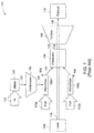
- FIG. 1 illustrates a block diagram of a prior art gas turbine system 100 including a compressor 102, a combustor 104, a turbine 106, and a micromixer system 108 having a plurality of micromixers 108a, 108b.
- the compressor 102 is coupled to the combustor 104 via at least one micromixer 108a.
- the combustor 104 is coupled to the turbine 106.
- each micromixer 108a, 108b includes a plurality of pipes (not shown in FIG. 1 ). Each pipe is spaced apart from each other and disposed within a casing (not shown in FIG. 1 ). The number of micromixers may vary depending upon an application and design criteria.
- Rotation of a plurality of blades (not shown in FIG. 1 ) of the compressor 102 increases pressure of air 122 received through an intake guide vane 120, to generate a compressed air 126.
- the air 122 may be a pressurized oxidant such as oxygen, oxygen-enriched air, oxygen reduced air, or any combination thereof.
- the compressed air 126 and a first fuel 110a are fed to the micromixer 108a.
- a second fuel 110b is fed directly to the other micromixer 108b.
- the first and second fuels 110a, 110b may include a liquid fuel such as petrol or diesel and/or a gaseous fuel such as natural gas or syngas.
- each micromixer 108a, 108b may be configured to receive the first fuel 110a, the second fuel 110b, and the compressed air 126. It should be noted herein that the configuration of the plurality of micromixers 108a, 108b may vary depending on an application and design criteria.
- the first fuel 110a fed to the micro mixer 108a may be different from the second fuel 110b fed to the other micro mixer 108b. In certain other embodiments, the first fuel 110a and the second fuel 110b may be the same.
- the compressed air 126 and the first fuel 110a are mixed within the micromixer 108a to generate an air-fuel mixture 128.
- the combustor 104 receives the air-fuel mixture 128 from the micromixer 108a and the second fuel 110b from the other micromixer 108b.
- the air-fuel mixture 128 and the second fuel 110b are combusted within the combustor 104 to generate a combustion gas 124.
- the combustion gas 124 is then fed to the turbine 106.
- the turbine 106 includes a plurality of blades (not shown in FIG. 1 ), coupled to a load 114 via a shaft 116.
- the plurality of blades is rotated, causing the rotation of the shaft 116.
- the load 114 is powered by the rotation of the shaft 116.
- the load 114 may be an electrical generator, a propeller of an airplane, or the like.
- An expanded gas 130 generated from the turbine 106 then exits via an exhaust outlet 118.
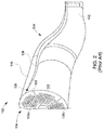
- FIG. 2 is a perspective view of a portion 132 of the gas turbine system 100 of FIG. 1 illustrating the combustor 104 and a portion 134 of the micromixer system 108.
- the combustor 104 includes an upstream head-end 136 which is coupled to the micromixers 108a, 108b.
- the combustor 104 further includes a liner 138 and a flow sleeve 140 spaced radially outward and enclosing the liner 138.
- the combustor 104 includes a downstream end 142 disposed proximate to the turbine 106.
- a combustion chamber of the combustor 104 is represented by a reference numeral 144.
- FIG. 3 illustrates a perspective view of a micromixer system 308 in accordance with one exemplary embodiment of the present invention.
- the micromixer 308 includes a casing 146, a plurality of pipes 148, a first plenum 150, a second plenum 152, and a plurality of openings 154.
- the casing 146 includes a first side wall 156, a second side wall 158, and an intermediate wall 160.
- the first side wall 156 is coupled to the second side wall 158 through the intermediate wall 160.
- the plurality of pipes 148 is spaced apart from each other and disposed within the casing 146.
- Each pipe 148 includes an inlet 162 and an outlet 164.
- the inlet 162 is disposed in the first side wall 156 and the outlet 164 is disposed in the second side wall 158. In certain other embodiments, the inlet 162 and the outlet 164 may protrude outwards from the first and second side walls 156, 158 respectively.
- the plurality of openings 154 is disposed surrounding the outlets 164 of at least some pipes 148, in the second side wall 158.
- Each pipe 148 includes at least one hole 166 for fluidically coupling to the first plenum 150.
- Each pipe 148 may have a diameter ranging approximately from about 0.5 centimeters to about 2.0 centimeters.
- the plurality of pipes 148 is arranged in parallel in the form of one or more bundles of closely spaced tubes. In certain other embodiments, the plurality of pipes 148 may be arranged in the form of coils having a helical profile.
- Each pipe 148 is configured to direct the air-fuel mixture 128 into the combustion chamber 144 (shown in FIG. 2 ) of the combustor. Specifically, the air-fuel mixture 128 is fed through the outlet 164 and only the second fuel 110b is fed through the plurality of openings 154, to the combustion chamber.
- the first plenum 150 is formed within the casing 146 and disposed around a first portion 168 of the plurality of pipes 148.
- the first portion 168 of the plurality of pipes 148 is located proximate to the first side wall 156.
- the first plenum 150 includes a first boundary wall 170 coupled to the first side wall 156 and a second boundary wall 172 positioned proximate to the second plenum 152.
- the first plenum 150 includes two chambers 150a, 150b, which are fluidically coupled to each other through one or more holes (not shown in FIG. 3 ).
- the first chamber 150a is disposed proximate to the first side wall 156 and the second chamber 150b is disposed proximate to the second plenum 152.
- the first plenum 150 includes a plurality of first inlets 174a, 174b formed in the intermediate wall 160. The first inlets 174a, 174b are fluidically coupled to the first chamber 150a and the second chamber 150b respectively.
- the second plenum 152 is formed within the casing 146 and disposed around a second portion 176 of the plurality of pipes 148.
- the second portion 176 of the plurality of pipes 148 is located proximate to the second side wall 158.
- the second plenum 152 includes a first boundary wall 178 positioned proximate to the second boundary wall 172 of the first plenum 150 and a second boundary wall 180 coupled to the second side wall 158.
- the second boundary wall 172 of the first plenum 150 and the first boundary wall 178 of the second plenum 152 are separated from each other by a gap 182.
- the second plenum 152 includes a second inlet 184 fluidically coupled to a tube 186 having an opening 188 formed in the first side wall 156.
- the opening 188 is disposed at the center of the first side wall 156.
- the second inlet 184 may be disposed on the intermediate wall 160 and fluidically coupled directly to the second plenum 152.
- each pipe 148 receives the compressed air 126 through the inlet 162.
- the two chambers 150a, 150b of the first plenum 150 receives the first fuel 110a through the first inlets 174a, 174b.
- the first fuel 110a is fed from the two chambers 150a, 150b into each pipe 148 via the one or more holes 166.
- the first fuel 110a is then mixed with the compressed air 126 within each pipe 148 to generate the air-fuel mixture 128.
- the air-fuel mixture 128 is then directed through the outlet 164 of each pipe 148.
- the second fuel 110b is fed through the tube 186 to the second inlet 184 of the second plenum 152.
- the second fuel 110b is then fed through the plurality of openings 154.
- FIG. 4 illustrates a schematic view of a portion 190 of the micromixer system 308 in accordance with the exemplary embodiment of FIG. 3 .
- the portion 190 illustrates an exit of the micromixer system 308.
- the plurality of openings 154 is disposed surrounding the outlet 164 of each pipe 148, in the second side wall 158.
- Each opening 154 is fluidically coupled to the second plenum 152 via a corresponding channel from a plurality of channels 192 formed in the second side wall 158.
- the air-fuel mixture 128 is directed through the outlet 164 of each pipe 148 into the combustion chamber 144.
- the air-fuel mixture 128 is then combusted in the combustion chamber 144 to generate a first flame 194.
- the second fuel 110b is directed through the corresponding channel 192 and each opening 154 into the combustion chamber 144. Specifically, the second fuel 110b is directed to the air-fuel mixture 128 in the combustion chamber 144.
- the second fuel 110b is then combusted in the combustion chamber 144 to generate a second flame 196 that then intersects with the first flame 194.
- the gas turbine system 100 may include a plurality of sensors (not shown in FIG. 4 ) communicatively coupled to a control unit (not shown in FIG. 4 ) for regulating a flow of the first fuel 110a and the second fuel 110b.
- the plurality of sensors may include an acoustics sensor, an emission sensor, and/or a speed sensor, for example.
- the control unit may include a processor-based device.
- the plurality of sensors may be configured to generate a plurality of input signals based on sensed parameters of the gas turbine system 100.
- the control unit may be configured to generate one or more control signals based on the plurality of input signals for regulating one or more valves (not shown in FIG. 4 ) so as to control feeding of the first fuel 110a and the second fuel 110b respectively to the combustion chamber 144.
- the control of the flow of the first fuel 110a in the air-fuel mixture 128 and the second fuel 110b to the combustion chamber 144 may be based on a power level and acoustics level requirement of the gas turbine system 100.
- the power level requirement may be related to a low flame temperature condition and a full speed and/or no load condition of the gas turbine system 100.
- the acoustics level requirement is limited by accompanying vibrations of the gas turbine system 100.
- a substantially low quantity of the first fuel 110a in the air-fuel mixture 128 and a substantially high quantity of the second fuel 110b may be fed into the combustion chamber 144 to operate the gas turbine system 100 at a low flame temperature condition, a full speed and/or a no load condition, and high vibrations of the gas turbine system 100. Varying the quantity of supply of the first fuel 110a in the air-fuel mixture 128 and the second fuel 110b to the combustion chamber 144 increases a turndown capability of the gas turbine system 100 and enables a very stable combustion with a substantially low emission. It should be noted herein that the term "a turndown" means an ability to sustain flame from a very low temperature condition to a very high temperature condition.
- a substantially high quantity of the air-fuel mixture 128 and a substantially low quantity of the second fuel 110b may be fed to the combustion chamber 144 to operate the gas turbine system 100 at a normal operating condition and generate low NOx emissions.
- the quantity of first fuel 110a in the air-fuel mixture 128 may be in a range of about 0 percent to about 100 percent and the quantity of second fuel 110b may be in a range of about 20 percent to about 100 percent.
- the quantity of the second fuel 110b may vary based on one or more operating conditions of the gas turbine system 100.
- the second fuel 110b is used to balance an overall fuel required to generate a required amount of power ( i.e. flame) from the gas turbine system 100.
- FIG. 5 illustrates a schematic view of a micromixer system 408 in accordance with another exemplary embodiment.
- An annular gap 254 is formed around a circumference 265 of an outlet 264 of a respective pipe from a plurality of pipes 248 rather than the plurality of openings 154 formed surrounding the outlet 164 of the respective pipe 148 as shown in the embodiment of FIGS. 3 and 4 .
- a casing 246 includes a first side wall 256, a second side wall 258, and an intermediate wall 260.
- the first side wall 256 is coupled to the second side wall 258 through the intermediate wall 260.
- the plurality of pipes 248 is spaced apart from each other and disposed within the casing 246.
- Each pipe 248 includes an inlet 262 and the outlet 264.
- the inlet 262 is disposed in the first side wall 256 and the outlet 264 is disposed in the second side wall 258.
- Each pipe 248 includes at least one hole 266 for fluidically coupling to the first plenum 250.
- the inlet 262 and the outlet 264 protrude outwards from the first and second side walls 256, 258 respectively.
- the first plenum 250 is formed within the casing 246 and disposed around a first portion 268 of the plurality of pipes 248.
- the first plenum 250 includes a first inlet 274 disposed in the first side wall 256.
- the second plenum 252 is formed within the casing 246 and disposed around a second portion 276 of the plurality of pipes 248.
- the second plenum 252 includes a second inlet 284 disposed in the intermediate wall 260.
- the micromixer system 408 further includes an effusion plate 300 disposed proximate to the second side wall 258 and around a sub-portion 302 of the second portion 276 of the plurality of pipes 248.
- the effusion plate 300 defines an effusion area 304 between the second side wall 258 and the effusion plate 300.
- the effusion plate 300 includes a plurality of through-holes 306 for fluidically coupling the second plenum 252 to the effusion area 304.
- the annular gaps 254 is formed in the second side wall 258, around the circumferences 265 of the outlets 264 of at least some pipes of the plurality of pipes 248.
- the annular gaps 254 are fluidically coupled to the second plenum 252 through the effusion area 304.
- each pipe 248 receives compressed air 226 through the inlet 262 and the first plenum 250 receives a first fuel 210a through the first inlet 274.
- the first fuel 210a is fed from the first plenum 250 into each pipe 248 via the at least one hole 266.
- the compressed air 226 and the first fuel 210a are mixed within each pipe 248 to generate an air-fuel mixture 228.
- the air-fuel mixture 228 is then directed through the outlet 264 of each pipe 248.
- the second plenum 252 receives a second fuel 210b via the second inlet 284.
- the second fuel 210b is fed from the second plenum 252 into the effusion area 304 via the plurality of through-holes 306.
- the second fuel 210b is then fed from the effusion area 304 via the annular gaps 254 resulting in cooling of at least a portion of the second side wall 258.
- FIG. 6 illustrates a schematic view of a portion 290 of the micromixer system 408 in accordance with the exemplary embodiment of FIG. 5 .
- the portion 290 illustrates an exit of the micromixer system 408.
- the air-fuel mixture 228 is directed through the outlet 264 of each pipe 248 into a combustion chamber 244.
- the air-fuel mixture 228 is combusted in the combustion chamber 244 to generate a first flame 294.
- the second fuel 210b is directed through each opening 254 ( i.e. annular gap) into the combustion chamber 244. Specifically, the second fuel 210b is directed to the air-fuel mixture 228 in the combustion chamber 244. The second fuel 210b is then combusted in the combustion chamber 244 to generate a second flame 296 that then intersects with the first flame 294.
- the quantity of the second fuel 210b and the first fuel 210a in the air-fuel mixture 228 fed to the combustion chamber 244 may be regulated based on operating conditions of the gas turbine system 100.
- an exemplary micromixer system facilitates to enhance a turndown capability of a turbine system by varying a quantity of a second fuel fed to a combustion chamber during a full speed and/or no load condition of the turbine system. Further, the micromixer system facilitates a very stable combustion environment within a combustor resulting in a substantially low emission. The micromixer enables to operate the combustor without loosing the flame during a low flame temperature condition.
Applications Claiming Priority (1)
| Application Number | Priority Date | Filing Date | Title |
|---|---|---|---|
| US14/675,827 US10101032B2 (en) | 2015-04-01 | 2015-04-01 | Micromixer system for a turbine system and an associated method thereof |
Publications (2)
| Publication Number | Publication Date |
|---|---|
| EP3076085A1 true EP3076085A1 (fr) | 2016-10-05 |
| EP3076085B1 EP3076085B1 (fr) | 2019-06-12 |
Family
ID=55650240
Family Applications (1)
| Application Number | Title | Priority Date | Filing Date |
|---|---|---|---|
| EP16162679.1A Active EP3076085B1 (fr) | 2015-04-01 | 2016-03-29 | Micromélangeur pour un système de turbine et son procédé associé |
Country Status (4)
| Country | Link |
|---|---|
| US (1) | US10101032B2 (fr) |
| EP (1) | EP3076085B1 (fr) |
| JP (1) | JP6754203B2 (fr) |
| CN (1) | CN106051823B (fr) |
Families Citing this family (13)
| Publication number | Priority date | Publication date | Assignee | Title |
|---|---|---|---|---|
| US10890329B2 (en) | 2018-03-01 | 2021-01-12 | General Electric Company | Fuel injector assembly for gas turbine engine |
| US10767866B2 (en) | 2018-07-11 | 2020-09-08 | General Electric Company | Micromixer for use with liquid fuel |
| US10935245B2 (en) | 2018-11-20 | 2021-03-02 | General Electric Company | Annular concentric fuel nozzle assembly with annular depression and radial inlet ports |
| JP2020085284A (ja) * | 2018-11-20 | 2020-06-04 | 三菱日立パワーシステムズ株式会社 | 燃焼器及びガスタービン |
| US11073114B2 (en) | 2018-12-12 | 2021-07-27 | General Electric Company | Fuel injector assembly for a heat engine |
| US11286884B2 (en) | 2018-12-12 | 2022-03-29 | General Electric Company | Combustion section and fuel injector assembly for a heat engine |
| US11156360B2 (en) | 2019-02-18 | 2021-10-26 | General Electric Company | Fuel nozzle assembly |
| KR102154220B1 (ko) * | 2019-04-05 | 2020-09-09 | 두산중공업 주식회사 | 연소기 및 이를 포함하는 가스터빈 |
| US11486317B2 (en) * | 2019-08-30 | 2022-11-01 | General Electric Company | Gas turbine fuel system |
| EP3978807A3 (fr) | 2020-09-30 | 2022-07-06 | Rolls-Royce plc | Système d'injection directe de carburant |
| KR102403750B1 (ko) * | 2021-01-15 | 2022-05-30 | 두산에너빌리티 주식회사 | 멀티 튜브를 갖는 연소기용 노즐, 연소기, 및 이를 포함하는 가스 터빈 |
| JPWO2022249938A1 (fr) * | 2021-05-28 | 2022-12-01 | ||
| US11454396B1 (en) | 2021-06-07 | 2022-09-27 | General Electric Company | Fuel injector and pre-mixer system for a burner array |
Citations (3)
| Publication number | Priority date | Publication date | Assignee | Title |
|---|---|---|---|---|
| US20110016871A1 (en) * | 2009-07-23 | 2011-01-27 | General Electric Company | Gas turbine premixing systems |
| US20110083439A1 (en) * | 2009-10-08 | 2011-04-14 | General Electric Corporation | Staged Multi-Tube Premixing Injector |
| US20130239581A1 (en) * | 2012-03-19 | 2013-09-19 | General Electric Company | Systems and Methods for Preventing Flashback in a Combustor Assembly |
Family Cites Families (19)
| Publication number | Priority date | Publication date | Assignee | Title |
|---|---|---|---|---|
| US4100733A (en) * | 1976-10-04 | 1978-07-18 | United Technologies Corporation | Premix combustor |
| JP2528894B2 (ja) * | 1987-09-04 | 1996-08-28 | 株式会社日立製作所 | ガスタ―ビン燃焼器 |
| US5339635A (en) * | 1987-09-04 | 1994-08-23 | Hitachi, Ltd. | Gas turbine combustor of the completely premixed combustion type |
| JPH0743137B2 (ja) * | 1989-02-15 | 1995-05-15 | 株式会社東芝 | ガスタービン燃焼器 |
| JP2002039533A (ja) | 2000-07-21 | 2002-02-06 | Mitsubishi Heavy Ind Ltd | 燃焼器、ガスタービン及びジェットエンジン |
| US6598584B2 (en) | 2001-02-23 | 2003-07-29 | Clean Air Partners, Inc. | Gas-fueled, compression ignition engine with maximized pilot ignition intensity |
| JP3962554B2 (ja) | 2001-04-19 | 2007-08-22 | 三菱重工業株式会社 | ガスタービン燃焼器及びガスタービン |
| US20030101729A1 (en) | 2001-12-05 | 2003-06-05 | Honeywell International, Inc. | Retrofittable air assisted fuel injection method to control gaseous and acoustic emissions |
| US7966801B2 (en) | 2006-12-07 | 2011-06-28 | General Electric Company | Apparatus and method for gas turbine active combustion control system |
| US8145403B2 (en) * | 2008-12-31 | 2012-03-27 | General Electric Company | Operating a turbine at baseload on cold fuel with hot fuel combustion hardware |
| US9140454B2 (en) * | 2009-01-23 | 2015-09-22 | General Electric Company | Bundled multi-tube nozzle for a turbomachine |
| JP5103454B2 (ja) * | 2009-09-30 | 2012-12-19 | 株式会社日立製作所 | 燃焼器 |
| US8590311B2 (en) | 2010-04-28 | 2013-11-26 | General Electric Company | Pocketed air and fuel mixing tube |
| US8955327B2 (en) | 2011-08-16 | 2015-02-17 | General Electric Company | Micromixer heat shield |
| US8984887B2 (en) * | 2011-09-25 | 2015-03-24 | General Electric Company | Combustor and method for supplying fuel to a combustor |
| US9074773B2 (en) | 2012-02-07 | 2015-07-07 | General Electric Company | Combustor assembly with trapped vortex cavity |
| US9212822B2 (en) * | 2012-05-30 | 2015-12-15 | General Electric Company | Fuel injection assembly for use in turbine engines and method of assembling same |
| US8904798B2 (en) * | 2012-07-31 | 2014-12-09 | General Electric Company | Combustor |
| US9285121B2 (en) * | 2012-08-23 | 2016-03-15 | General Electric Company | Gas turbine cooling circuit including a seal for a perforated plate |
-
2015
- 2015-04-01 US US14/675,827 patent/US10101032B2/en active Active
-
2016
- 2016-03-22 JP JP2016056432A patent/JP6754203B2/ja active Active
- 2016-03-29 EP EP16162679.1A patent/EP3076085B1/fr active Active
- 2016-04-01 CN CN201610198597.4A patent/CN106051823B/zh active Active
Patent Citations (3)
| Publication number | Priority date | Publication date | Assignee | Title |
|---|---|---|---|---|
| US20110016871A1 (en) * | 2009-07-23 | 2011-01-27 | General Electric Company | Gas turbine premixing systems |
| US20110083439A1 (en) * | 2009-10-08 | 2011-04-14 | General Electric Corporation | Staged Multi-Tube Premixing Injector |
| US20130239581A1 (en) * | 2012-03-19 | 2013-09-19 | General Electric Company | Systems and Methods for Preventing Flashback in a Combustor Assembly |
Also Published As
| Publication number | Publication date |
|---|---|
| CN106051823B (zh) | 2020-11-27 |
| US20160290650A1 (en) | 2016-10-06 |
| JP6754203B2 (ja) | 2020-09-09 |
| CN106051823A (zh) | 2016-10-26 |
| JP2016194405A (ja) | 2016-11-17 |
| US10101032B2 (en) | 2018-10-16 |
| EP3076085B1 (fr) | 2019-06-12 |
Similar Documents
| Publication | Publication Date | Title |
|---|---|---|
| EP3076085B1 (fr) | Micromélangeur pour un système de turbine et son procédé associé | |
| US5640851A (en) | Gas turbine engine combustion chamber | |
| EP1672282B1 (fr) | Procédé et appareil pour réduire les oscillations acoustiques de combustion | |
| US9534787B2 (en) | Micromixing cap assembly | |
| EP1924762B1 (fr) | Systemes de combustion pour turbine a gaz | |
| US10415479B2 (en) | Fuel/air mixing system for fuel nozzle | |
| US9671112B2 (en) | Air diffuser for a head end of a combustor | |
| US8881531B2 (en) | Gas turbine engine premix injectors | |
| US20100011771A1 (en) | Coanda injection system for axially staged low emission combustors | |
| EP2613086A2 (fr) | Prémélangeur air-carburant pour chambre à combustion de turbine à gaz avec appareil de tourbillonnement variable | |
| EP0161561A1 (fr) | Chambre de combustion pour turbine à gaz avec circulation d'air réglable par action pneumatique | |
| EP2206958A2 (fr) | Procédé et appareil pour l'injection de carburant dans un moteur à turbine | |
| US4463568A (en) | Fuel injector for gas turbine engines | |
| EP2904326A2 (fr) | Dôme de chambre de combustion à flamme mince | |
| US9151503B2 (en) | Coaxial fuel supply for a micromixer | |
| EP3845812A1 (fr) | Ensemble extrémité de tête de chambre de combustion comportant des buses de prémélange à double pression | |
| JP2009074706A (ja) | ガスタービン燃焼器 | |
| EP3425281B1 (fr) | Buse pilote dotée de prémélange en ligne | |
| US20080295521A1 (en) | Method and apparatus for assembling turbine engines | |
| US6880339B2 (en) | Combination of a premixing chamber and a combustion chamber, with low emission of pollutants, for gas turbines running on liquid and/or gas fuel | |
| US10352570B2 (en) | Turbine engine fuel injection system and methods of assembling the same | |
| RU2002134603A (ru) | Усовершенствованная комбинация камеры предварительного смешивания и камеры сгорания с малым уровнем выброса загрязняющих окружающую среду веществ для газовых турбин, работающих на жидком и/или газообразном топливе | |
| CA2443979A1 (fr) | Turbine dotee d'un premelangeur de chambre de combustion | |
| EP2825823B1 (fr) | Système de combustion de turbine à gaz et procédé de stabilisation de la flamme dans un tel système | |
| US10767866B2 (en) | Micromixer for use with liquid fuel |
Legal Events
| Date | Code | Title | Description |
|---|---|---|---|
| PUAI | Public reference made under article 153(3) epc to a published international application that has entered the european phase |
Free format text: ORIGINAL CODE: 0009012 |
|
| AK | Designated contracting states |
Kind code of ref document: A1 Designated state(s): AL AT BE BG CH CY CZ DE DK EE ES FI FR GB GR HR HU IE IS IT LI LT LU LV MC MK MT NL NO PL PT RO RS SE SI SK SM TR |
|
| AX | Request for extension of the european patent |
Extension state: BA ME |
|
| STAA | Information on the status of an ep patent application or granted ep patent |
Free format text: STATUS: REQUEST FOR EXAMINATION WAS MADE |
|
| 17P | Request for examination filed |
Effective date: 20170405 |
|
| RBV | Designated contracting states (corrected) |
Designated state(s): AL AT BE BG CH CY CZ DE DK EE ES FI FR GB GR HR HU IE IS IT LI LT LU LV MC MK MT NL NO PL PT RO RS SE SI SK SM TR |
|
| STAA | Information on the status of an ep patent application or granted ep patent |
Free format text: STATUS: EXAMINATION IS IN PROGRESS |
|
| 17Q | First examination report despatched |
Effective date: 20171115 |
|
| GRAP | Despatch of communication of intention to grant a patent |
Free format text: ORIGINAL CODE: EPIDOSNIGR1 |
|
| STAA | Information on the status of an ep patent application or granted ep patent |
Free format text: STATUS: GRANT OF PATENT IS INTENDED |
|
| RIC1 | Information provided on ipc code assigned before grant |
Ipc: F23R 3/36 20060101ALI20190201BHEP Ipc: F23R 3/32 20060101ALI20190201BHEP Ipc: F23D 14/62 20060101ALI20190201BHEP Ipc: F23R 3/28 20060101AFI20190201BHEP |
|
| INTG | Intention to grant announced |
Effective date: 20190220 |
|
| GRAS | Grant fee paid |
Free format text: ORIGINAL CODE: EPIDOSNIGR3 |
|
| GRAA | (expected) grant |
Free format text: ORIGINAL CODE: 0009210 |
|
| STAA | Information on the status of an ep patent application or granted ep patent |
Free format text: STATUS: THE PATENT HAS BEEN GRANTED |
|
| REG | Reference to a national code |
Ref country code: DE Ref legal event code: R081 Ref document number: 602016015008 Country of ref document: DE Owner name: GENERAL ELECTRIC TECHNOLOGY GMBH, CH Free format text: FORMER OWNER: GENERAL ELECTRIC COMPANY, NEW YORK, N.Y., US |
|
| AK | Designated contracting states |
Kind code of ref document: B1 Designated state(s): AL AT BE BG CH CY CZ DE DK EE ES FI FR GB GR HR HU IE IS IT LI LT LU LV MC MK MT NL NO PL PT RO RS SE SI SK SM TR |
|
| REG | Reference to a national code |
Ref country code: GB Ref legal event code: FG4D |
|
| REG | Reference to a national code |
Ref country code: CH Ref legal event code: EP |
|
| REG | Reference to a national code |
Ref country code: AT Ref legal event code: REF Ref document number: 1143049 Country of ref document: AT Kind code of ref document: T Effective date: 20190615 |
|
| REG | Reference to a national code |
Ref country code: DE Ref legal event code: R096 Ref document number: 602016015008 Country of ref document: DE |
|
| REG | Reference to a national code |
Ref country code: IE Ref legal event code: FG4D |
|
| REG | Reference to a national code |
Ref country code: NL Ref legal event code: MP Effective date: 20190612 |
|
| REG | Reference to a national code |
Ref country code: LT Ref legal event code: MG4D |
|
| PG25 | Lapsed in a contracting state [announced via postgrant information from national office to epo] |
Ref country code: SE Free format text: LAPSE BECAUSE OF FAILURE TO SUBMIT A TRANSLATION OF THE DESCRIPTION OR TO PAY THE FEE WITHIN THE PRESCRIBED TIME-LIMIT Effective date: 20190612 Ref country code: HR Free format text: LAPSE BECAUSE OF FAILURE TO SUBMIT A TRANSLATION OF THE DESCRIPTION OR TO PAY THE FEE WITHIN THE PRESCRIBED TIME-LIMIT Effective date: 20190612 Ref country code: AL Free format text: LAPSE BECAUSE OF FAILURE TO SUBMIT A TRANSLATION OF THE DESCRIPTION OR TO PAY THE FEE WITHIN THE PRESCRIBED TIME-LIMIT Effective date: 20190612 Ref country code: NO Free format text: LAPSE BECAUSE OF FAILURE TO SUBMIT A TRANSLATION OF THE DESCRIPTION OR TO PAY THE FEE WITHIN THE PRESCRIBED TIME-LIMIT Effective date: 20190912 Ref country code: FI Free format text: LAPSE BECAUSE OF FAILURE TO SUBMIT A TRANSLATION OF THE DESCRIPTION OR TO PAY THE FEE WITHIN THE PRESCRIBED TIME-LIMIT Effective date: 20190612 Ref country code: LT Free format text: LAPSE BECAUSE OF FAILURE TO SUBMIT A TRANSLATION OF THE DESCRIPTION OR TO PAY THE FEE WITHIN THE PRESCRIBED TIME-LIMIT Effective date: 20190612 |
|
| PG25 | Lapsed in a contracting state [announced via postgrant information from national office to epo] |
Ref country code: GR Free format text: LAPSE BECAUSE OF FAILURE TO SUBMIT A TRANSLATION OF THE DESCRIPTION OR TO PAY THE FEE WITHIN THE PRESCRIBED TIME-LIMIT Effective date: 20190913 Ref country code: BG Free format text: LAPSE BECAUSE OF FAILURE TO SUBMIT A TRANSLATION OF THE DESCRIPTION OR TO PAY THE FEE WITHIN THE PRESCRIBED TIME-LIMIT Effective date: 20190912 Ref country code: RS Free format text: LAPSE BECAUSE OF FAILURE TO SUBMIT A TRANSLATION OF THE DESCRIPTION OR TO PAY THE FEE WITHIN THE PRESCRIBED TIME-LIMIT Effective date: 20190612 Ref country code: LV Free format text: LAPSE BECAUSE OF FAILURE TO SUBMIT A TRANSLATION OF THE DESCRIPTION OR TO PAY THE FEE WITHIN THE PRESCRIBED TIME-LIMIT Effective date: 20190612 |
|
| REG | Reference to a national code |
Ref country code: AT Ref legal event code: MK05 Ref document number: 1143049 Country of ref document: AT Kind code of ref document: T Effective date: 20190612 |
|
| PG25 | Lapsed in a contracting state [announced via postgrant information from national office to epo] |
Ref country code: NL Free format text: LAPSE BECAUSE OF FAILURE TO SUBMIT A TRANSLATION OF THE DESCRIPTION OR TO PAY THE FEE WITHIN THE PRESCRIBED TIME-LIMIT Effective date: 20190612 Ref country code: AT Free format text: LAPSE BECAUSE OF FAILURE TO SUBMIT A TRANSLATION OF THE DESCRIPTION OR TO PAY THE FEE WITHIN THE PRESCRIBED TIME-LIMIT Effective date: 20190612 Ref country code: EE Free format text: LAPSE BECAUSE OF FAILURE TO SUBMIT A TRANSLATION OF THE DESCRIPTION OR TO PAY THE FEE WITHIN THE PRESCRIBED TIME-LIMIT Effective date: 20190612 Ref country code: CZ Free format text: LAPSE BECAUSE OF FAILURE TO SUBMIT A TRANSLATION OF THE DESCRIPTION OR TO PAY THE FEE WITHIN THE PRESCRIBED TIME-LIMIT Effective date: 20190612 Ref country code: RO Free format text: LAPSE BECAUSE OF FAILURE TO SUBMIT A TRANSLATION OF THE DESCRIPTION OR TO PAY THE FEE WITHIN THE PRESCRIBED TIME-LIMIT Effective date: 20190612 Ref country code: SK Free format text: LAPSE BECAUSE OF FAILURE TO SUBMIT A TRANSLATION OF THE DESCRIPTION OR TO PAY THE FEE WITHIN THE PRESCRIBED TIME-LIMIT Effective date: 20190612 Ref country code: PT Free format text: LAPSE BECAUSE OF FAILURE TO SUBMIT A TRANSLATION OF THE DESCRIPTION OR TO PAY THE FEE WITHIN THE PRESCRIBED TIME-LIMIT Effective date: 20191014 |
|
| PG25 | Lapsed in a contracting state [announced via postgrant information from national office to epo] |
Ref country code: IS Free format text: LAPSE BECAUSE OF FAILURE TO SUBMIT A TRANSLATION OF THE DESCRIPTION OR TO PAY THE FEE WITHIN THE PRESCRIBED TIME-LIMIT Effective date: 20191012 Ref country code: SM Free format text: LAPSE BECAUSE OF FAILURE TO SUBMIT A TRANSLATION OF THE DESCRIPTION OR TO PAY THE FEE WITHIN THE PRESCRIBED TIME-LIMIT Effective date: 20190612 Ref country code: IT Free format text: LAPSE BECAUSE OF FAILURE TO SUBMIT A TRANSLATION OF THE DESCRIPTION OR TO PAY THE FEE WITHIN THE PRESCRIBED TIME-LIMIT Effective date: 20190612 Ref country code: ES Free format text: LAPSE BECAUSE OF FAILURE TO SUBMIT A TRANSLATION OF THE DESCRIPTION OR TO PAY THE FEE WITHIN THE PRESCRIBED TIME-LIMIT Effective date: 20190612 |
|
| REG | Reference to a national code |
Ref country code: DE Ref legal event code: R097 Ref document number: 602016015008 Country of ref document: DE |
|
| PG25 | Lapsed in a contracting state [announced via postgrant information from national office to epo] |
Ref country code: TR Free format text: LAPSE BECAUSE OF FAILURE TO SUBMIT A TRANSLATION OF THE DESCRIPTION OR TO PAY THE FEE WITHIN THE PRESCRIBED TIME-LIMIT Effective date: 20190612 |
|
| PLBE | No opposition filed within time limit |
Free format text: ORIGINAL CODE: 0009261 |
|
| STAA | Information on the status of an ep patent application or granted ep patent |
Free format text: STATUS: NO OPPOSITION FILED WITHIN TIME LIMIT |
|
| PG25 | Lapsed in a contracting state [announced via postgrant information from national office to epo] |
Ref country code: DK Free format text: LAPSE BECAUSE OF FAILURE TO SUBMIT A TRANSLATION OF THE DESCRIPTION OR TO PAY THE FEE WITHIN THE PRESCRIBED TIME-LIMIT Effective date: 20190612 Ref country code: PL Free format text: LAPSE BECAUSE OF FAILURE TO SUBMIT A TRANSLATION OF THE DESCRIPTION OR TO PAY THE FEE WITHIN THE PRESCRIBED TIME-LIMIT Effective date: 20190612 |
|
| 26N | No opposition filed |
Effective date: 20200313 |
|
| PG25 | Lapsed in a contracting state [announced via postgrant information from national office to epo] |
Ref country code: IS Free format text: LAPSE BECAUSE OF FAILURE TO SUBMIT A TRANSLATION OF THE DESCRIPTION OR TO PAY THE FEE WITHIN THE PRESCRIBED TIME-LIMIT Effective date: 20200224 Ref country code: SI Free format text: LAPSE BECAUSE OF FAILURE TO SUBMIT A TRANSLATION OF THE DESCRIPTION OR TO PAY THE FEE WITHIN THE PRESCRIBED TIME-LIMIT Effective date: 20190612 |
|
| PG2D | Information on lapse in contracting state deleted |
Ref country code: IS |
|
| PG25 | Lapsed in a contracting state [announced via postgrant information from national office to epo] |
Ref country code: MC Free format text: LAPSE BECAUSE OF FAILURE TO SUBMIT A TRANSLATION OF THE DESCRIPTION OR TO PAY THE FEE WITHIN THE PRESCRIBED TIME-LIMIT Effective date: 20190612 |
|
| REG | Reference to a national code |
Ref country code: CH Ref legal event code: PL |
|
| REG | Reference to a national code |
Ref country code: BE Ref legal event code: MM Effective date: 20200331 |
|
| PG25 | Lapsed in a contracting state [announced via postgrant information from national office to epo] |
Ref country code: LU Free format text: LAPSE BECAUSE OF NON-PAYMENT OF DUE FEES Effective date: 20200329 |
|
| PG25 | Lapsed in a contracting state [announced via postgrant information from national office to epo] |
Ref country code: FR Free format text: LAPSE BECAUSE OF NON-PAYMENT OF DUE FEES Effective date: 20200331 Ref country code: LI Free format text: LAPSE BECAUSE OF NON-PAYMENT OF DUE FEES Effective date: 20200331 Ref country code: CH Free format text: LAPSE BECAUSE OF NON-PAYMENT OF DUE FEES Effective date: 20200331 Ref country code: IE Free format text: LAPSE BECAUSE OF NON-PAYMENT OF DUE FEES Effective date: 20200329 |
|
| PG25 | Lapsed in a contracting state [announced via postgrant information from national office to epo] |
Ref country code: BE Free format text: LAPSE BECAUSE OF NON-PAYMENT OF DUE FEES Effective date: 20200331 |
|
| GBPC | Gb: european patent ceased through non-payment of renewal fee |
Effective date: 20200329 |
|
| PG25 | Lapsed in a contracting state [announced via postgrant information from national office to epo] |
Ref country code: GB Free format text: LAPSE BECAUSE OF NON-PAYMENT OF DUE FEES Effective date: 20200329 |
|
| PG25 | Lapsed in a contracting state [announced via postgrant information from national office to epo] |
Ref country code: MT Free format text: LAPSE BECAUSE OF FAILURE TO SUBMIT A TRANSLATION OF THE DESCRIPTION OR TO PAY THE FEE WITHIN THE PRESCRIBED TIME-LIMIT Effective date: 20190612 Ref country code: CY Free format text: LAPSE BECAUSE OF FAILURE TO SUBMIT A TRANSLATION OF THE DESCRIPTION OR TO PAY THE FEE WITHIN THE PRESCRIBED TIME-LIMIT Effective date: 20190612 |
|
| PG25 | Lapsed in a contracting state [announced via postgrant information from national office to epo] |
Ref country code: MK Free format text: LAPSE BECAUSE OF FAILURE TO SUBMIT A TRANSLATION OF THE DESCRIPTION OR TO PAY THE FEE WITHIN THE PRESCRIBED TIME-LIMIT Effective date: 20190612 |
|
| PGFP | Annual fee paid to national office [announced via postgrant information from national office to epo] |
Ref country code: DE Payment date: 20230221 Year of fee payment: 8 |
|
| REG | Reference to a national code |
Ref country code: DE Ref legal event code: R082 Ref document number: 602016015008 Country of ref document: DE Ref country code: DE Ref legal event code: R081 Ref document number: 602016015008 Country of ref document: DE Owner name: GENERAL ELECTRIC TECHNOLOGY GMBH, CH Free format text: FORMER OWNER: GENERAL ELECTRIC COMPANY, SCHENECTADY, NY, US |
|
| PGFP | Annual fee paid to national office [announced via postgrant information from national office to epo] |
Ref country code: DE Payment date: 20240220 Year of fee payment: 9 |