EP3076004A1 - Valve assembly with a particle retainer element and fluid injection valve - Google Patents
Valve assembly with a particle retainer element and fluid injection valve Download PDFInfo
- Publication number
- EP3076004A1 EP3076004A1 EP15162310.5A EP15162310A EP3076004A1 EP 3076004 A1 EP3076004 A1 EP 3076004A1 EP 15162310 A EP15162310 A EP 15162310A EP 3076004 A1 EP3076004 A1 EP 3076004A1
- Authority
- EP
- European Patent Office
- Prior art keywords
- valve
- retainer element
- fluid
- particle retainer
- valve assembly
- Prior art date
- Legal status (The legal status is an assumption and is not a legal conclusion. Google has not performed a legal analysis and makes no representation as to the accuracy of the status listed.)
- Granted
Links
Images


Classifications
-
- F—MECHANICAL ENGINEERING; LIGHTING; HEATING; WEAPONS; BLASTING
- F02—COMBUSTION ENGINES; HOT-GAS OR COMBUSTION-PRODUCT ENGINE PLANTS
- F02M—SUPPLYING COMBUSTION ENGINES IN GENERAL WITH COMBUSTIBLE MIXTURES OR CONSTITUENTS THEREOF
- F02M51/00—Fuel-injection apparatus characterised by being operated electrically
- F02M51/06—Injectors peculiar thereto with means directly operating the valve needle
- F02M51/061—Injectors peculiar thereto with means directly operating the valve needle using electromagnetic operating means
- F02M51/0625—Injectors peculiar thereto with means directly operating the valve needle using electromagnetic operating means characterised by arrangement of mobile armatures
- F02M51/0664—Injectors peculiar thereto with means directly operating the valve needle using electromagnetic operating means characterised by arrangement of mobile armatures having a cylindrically or partly cylindrically shaped armature, e.g. entering the winding; having a plate-shaped or undulated armature entering the winding
- F02M51/0671—Injectors peculiar thereto with means directly operating the valve needle using electromagnetic operating means characterised by arrangement of mobile armatures having a cylindrically or partly cylindrically shaped armature, e.g. entering the winding; having a plate-shaped or undulated armature entering the winding the armature having an elongated valve body attached thereto
-
- F—MECHANICAL ENGINEERING; LIGHTING; HEATING; WEAPONS; BLASTING
- F02—COMBUSTION ENGINES; HOT-GAS OR COMBUSTION-PRODUCT ENGINE PLANTS
- F02M—SUPPLYING COMBUSTION ENGINES IN GENERAL WITH COMBUSTIBLE MIXTURES OR CONSTITUENTS THEREOF
- F02M51/00—Fuel-injection apparatus characterised by being operated electrically
- F02M51/06—Injectors peculiar thereto with means directly operating the valve needle
- F02M51/061—Injectors peculiar thereto with means directly operating the valve needle using electromagnetic operating means
-
- F—MECHANICAL ENGINEERING; LIGHTING; HEATING; WEAPONS; BLASTING
- F02—COMBUSTION ENGINES; HOT-GAS OR COMBUSTION-PRODUCT ENGINE PLANTS
- F02M—SUPPLYING COMBUSTION ENGINES IN GENERAL WITH COMBUSTIBLE MIXTURES OR CONSTITUENTS THEREOF
- F02M61/00—Fuel-injectors not provided for in groups F02M39/00 - F02M57/00 or F02M67/00
- F02M61/04—Fuel-injectors not provided for in groups F02M39/00 - F02M57/00 or F02M67/00 having valves, e.g. having a plurality of valves in series
- F02M61/10—Other injectors with elongated valve bodies, i.e. of needle-valve type
-
- F—MECHANICAL ENGINEERING; LIGHTING; HEATING; WEAPONS; BLASTING
- F02—COMBUSTION ENGINES; HOT-GAS OR COMBUSTION-PRODUCT ENGINE PLANTS
- F02M—SUPPLYING COMBUSTION ENGINES IN GENERAL WITH COMBUSTIBLE MIXTURES OR CONSTITUENTS THEREOF
- F02M61/00—Fuel-injectors not provided for in groups F02M39/00 - F02M57/00 or F02M67/00
- F02M61/16—Details not provided for in, or of interest apart from, the apparatus of groups F02M61/02 - F02M61/14
- F02M61/165—Filtering elements specially adapted in fuel inlets to injector
-
- F—MECHANICAL ENGINEERING; LIGHTING; HEATING; WEAPONS; BLASTING
- F02—COMBUSTION ENGINES; HOT-GAS OR COMBUSTION-PRODUCT ENGINE PLANTS
- F02M—SUPPLYING COMBUSTION ENGINES IN GENERAL WITH COMBUSTIBLE MIXTURES OR CONSTITUENTS THEREOF
- F02M61/00—Fuel-injectors not provided for in groups F02M39/00 - F02M57/00 or F02M67/00
- F02M61/16—Details not provided for in, or of interest apart from, the apparatus of groups F02M61/02 - F02M61/14
- F02M61/18—Injection nozzles, e.g. having valve seats; Details of valve member seated ends, not otherwise provided for
-
- F—MECHANICAL ENGINEERING; LIGHTING; HEATING; WEAPONS; BLASTING
- F16—ENGINEERING ELEMENTS AND UNITS; GENERAL MEASURES FOR PRODUCING AND MAINTAINING EFFECTIVE FUNCTIONING OF MACHINES OR INSTALLATIONS; THERMAL INSULATION IN GENERAL
- F16K—VALVES; TAPS; COCKS; ACTUATING-FLOATS; DEVICES FOR VENTING OR AERATING
- F16K1/00—Lift valves or globe valves, i.e. cut-off apparatus with closure members having at least a component of their opening and closing motion perpendicular to the closing faces
- F16K1/12—Lift valves or globe valves, i.e. cut-off apparatus with closure members having at least a component of their opening and closing motion perpendicular to the closing faces with streamlined valve member around which the fluid flows when the valve is opened
-
- F—MECHANICAL ENGINEERING; LIGHTING; HEATING; WEAPONS; BLASTING
- F16—ENGINEERING ELEMENTS AND UNITS; GENERAL MEASURES FOR PRODUCING AND MAINTAINING EFFECTIVE FUNCTIONING OF MACHINES OR INSTALLATIONS; THERMAL INSULATION IN GENERAL
- F16K—VALVES; TAPS; COCKS; ACTUATING-FLOATS; DEVICES FOR VENTING OR AERATING
- F16K31/00—Actuating devices; Operating means; Releasing devices
- F16K31/02—Actuating devices; Operating means; Releasing devices electric; magnetic
- F16K31/06—Actuating devices; Operating means; Releasing devices electric; magnetic using a magnet, e.g. diaphragm valves, cutting off by means of a liquid
- F16K31/0644—One-way valve
- F16K31/0655—Lift valves
- F16K31/0658—Armature and valve member being one single element
- F16K31/0662—Armature and valve member being one single element with a ball-shaped valve member
-
- F—MECHANICAL ENGINEERING; LIGHTING; HEATING; WEAPONS; BLASTING
- F02—COMBUSTION ENGINES; HOT-GAS OR COMBUSTION-PRODUCT ENGINE PLANTS
- F02M—SUPPLYING COMBUSTION ENGINES IN GENERAL WITH COMBUSTIBLE MIXTURES OR CONSTITUENTS THEREOF
- F02M2200/00—Details of fuel-injection apparatus, not otherwise provided for
- F02M2200/16—Sealing of fuel injection apparatus not otherwise provided for
-
- F—MECHANICAL ENGINEERING; LIGHTING; HEATING; WEAPONS; BLASTING
- F02—COMBUSTION ENGINES; HOT-GAS OR COMBUSTION-PRODUCT ENGINE PLANTS
- F02M—SUPPLYING COMBUSTION ENGINES IN GENERAL WITH COMBUSTIBLE MIXTURES OR CONSTITUENTS THEREOF
- F02M2200/00—Details of fuel-injection apparatus, not otherwise provided for
- F02M2200/27—Fuel-injection apparatus with filters
-
- F—MECHANICAL ENGINEERING; LIGHTING; HEATING; WEAPONS; BLASTING
- F16—ENGINEERING ELEMENTS AND UNITS; GENERAL MEASURES FOR PRODUCING AND MAINTAINING EFFECTIVE FUNCTIONING OF MACHINES OR INSTALLATIONS; THERMAL INSULATION IN GENERAL
- F16K—VALVES; TAPS; COCKS; ACTUATING-FLOATS; DEVICES FOR VENTING OR AERATING
- F16K31/00—Actuating devices; Operating means; Releasing devices
- F16K31/02—Actuating devices; Operating means; Releasing devices electric; magnetic
- F16K31/06—Actuating devices; Operating means; Releasing devices electric; magnetic using a magnet, e.g. diaphragm valves, cutting off by means of a liquid
Definitions
- the present disclosure relates to a valve assembly for a fluid injection valve, the valve assembly comprising a particle retainer element, and to a fluid injection valve.
- Fluid injection valves are used, for example as fuel injectors in order to inject fuel into combustion chambers of internal combustion engines.
- Fuel leakage from such fluid injection valves into the internal combustion engine can be detrimental for the combustion process or may even damage the combustion engine.
- Such leakage can occur due to contaminants which are flowing through the injection valve to the sealing surfaces where they may prevent a fluid tight closing of the injection valve.
- EP 2 060 777 A1 discloses an internal lower filter for a fuel injector which includes a self-supporting guide guiding a reciprocally activated valve of an internal valve assembly of a fuel injector.
- valve assembly for a fluid injection valve having the features of claim 1.
- Advantageous embodiments and developments of the valve assembly and the fluid injection valve are specified in the dependent claims, in the following description and in the drawings.
- a valve assembly for a fluid injection valve is specified according to one aspect of the present disclosure.
- a fluid injection valve which comprises the valve assembly is specified according to a further aspect of the present disclosure.
- the valve assembly comprises a valve body which has a longitudinal axis.
- the valve body has a cavity which extends axially through the valve body for hydraulically connecting a fluid inlet end of the valve body to a fluid outlet end of the valve body. Further, the valve body has a valve seat adjacent to the fluid outlet end.
- the valve body is assembled from a plurality of parts and comprises a main body and a seat body, the seat body comprising the valve seat.
- the seat body is in particular positioned adjacent to the fluid outlet end and may preferably close the cavity at the fluid outlet end, with the exception of one or more injection holes downstream of the valve seat which perforate the seat body.
- the seat body of the valve body is a one-pieced part.
- the valve assembly further comprises a valve needle.
- the valve needle is movably received in the cavity. In particular, it is axially displaceable in reciprocating fashion relative to the valve body.
- the valve needle is operable to sealingly contact the valve seat in a closing position of the valve needle.
- valve assembly comprises an armature.
- the armature is in particular a part of an electromagnetic actuator assembly of the fluid injection valve.
- the armature is configured and movably arranged in the cavity for displacing the valve needle axially away from the closing position.
- the electromagnetic actuator assembly comprises a pole piece which is positionally fix relative to the valve body. It may be in one piece with the valve body or it is positioned in the cavity.
- the electromagnetic actuator assembly may further expediently comprise a coil for generating a magnetic field to attract the armature towards the pole piece.
- the armature travels towards the pole piece and takes the valve needle with it to displace the valve needle axially, away from the closing position.
- the valve needle comprises an armature retainer and the armature is operable to engage into a form-fit connection with the armature retainer for axially moving the valve needle.
- the cavity of the valve body has a first portion and a second portion.
- the first portion accommodates the armature and is limited in axial direction towards the fluid outlet end by a bottom surface.
- the bottom surface has a central opening from which the second portion of the cavity extends towards the fluid outlet end.
- the first portion and/or the second portion have a generally cylindrical shape.
- the bottom surface preferably extends in radial direction at an interface of the first and second portions, so as to shape a step in the cavity.
- the valve needle has a shaft which extends through the opening into the second portion.
- the shaft extends, in axial direction from the fluid inlet end towards the fluid outlet end, from the retainer element through the armature, further through the first portion of the cavity and through the opening into the second portion of the cavity, in particular to a sealing element of the valve needle.
- the sealing element is preferably fixed to the shaft at a downstream end thereof and is in sealing mechanical contact with the valve seat when the valve needle is in the closing position.
- the sealing element is for example a ball which is attached to the downstream end of the shaft of the valve needle.
- the sealing element is in particular in mechanical contact with the valve seat when the valve needle is in the closing position.
- the sealing element is in sliding mechanical contact with the seat body for axially guiding the valve needle.
- valve assembly comprises a particle retainer element.
- the particle retainer element is positioned in the cavity in such fashion that it bears on the bottom surface of the first portion.
- the particle retainer element circumferentially surrounds the shaft of the valve needle. Further, the particle retainer element overlaps with the opening, in particular in top view along the longitudinal axis.
- the filter is positioned downstream of most movable parts of the valve assembly, in particular it is located downstream of the armature. In this way, the risk for particles being released from the valve assembly downstream of the particle retainer element is particularly small.
- the particle filter does not require lateral space around the valve needle adjacent to the fluid outlet end.
- the sealing element of the valve needle may be guided by direct mechanical contact with the - preferably one-pieced - seat element of the valve body in this way.
- the valve body may have particularly small lateral dimensions at its fluid outlet end.
- tolerances of the lateral position of the valve needle relative to the valve seat may be particularly small.
- manufacturing of the particle retainer element and assembling of the particle retainer element into the fluid injection valve may be particularly simple and/or cost-efficient.
- the valve assembly comprises fluid channels which are operable to guide fluid towards an outer edge region of the bottom surface.
- the fluid channels are comprised by the armature. Preferably, they extend obliquely with respect to the longitudinal axis. In other words, the radial distance of the fluid channels from the longitudinal axis increases in axial direction towards the fluid outlet end.
- the fluid channels are formed between an outer circumferential surface of the armature and the valve body.
- fluid is advantageously directed to flow radially inward along the bottom surface of the first portion of the cavity before entering the second portion through the opening in the bottom surface. In this way, a particularly high probability for retaining particles in the fluid flow by means of the particle retainer element is achievable.
- the particle retainer element has a flange portion which bears on the bottom surface. In this way, a particularly precise and reproducible axial position of the particle retainer element relative to the bottom surface is achievable.
- the particle retainer element has a circumferential inner edge which is radially offset with respect to an outer contour of the opening of the bottom surface in radial inward direction.
- the circumferential inner edge is positioned within the opening in top view along the longitudinal axis and preferably spaced apart from the outer contour of the opening.
- the circumferential inner edge defines a central aperture of the particle retainer element.
- the particle retainer element is generally ring-shaped in top view along the longitudinal axis.
- the shaft of the valve needle may expediently extend axially through the aperture. In this way, the particle retainer element can be particularly simply integrated in conventional valve designs.
- the particle retainer element comprises a trench portion for accommodating particles.
- the trench portion has a U-shaped cross section, i.e. in particular the trench portion is in the shape of a body of rotation resulting from rotating the U-shape around the longitudinal axis.
- the U-shape is preferably open in axial direction towards the fluid inlet end.
- the trench portion follows the flange portion in radial inward direction. For example, it is positioned between the flange portion and the circumferential inner edge in radial direction.
- the trench portion extends axially into the second portion of the cavity.
- an upstream surface of the particle retainer element extends, in the course from the flange portion to the circumferential inner edge, in radial inward direction, subsequently in axial direction towards the fluid inlet end, and subsequently in radial outward direction.
- the upstream surface of the particle retainer element has a generally U-shaped cross sectional area, the U-shape being open in radial outward direction, i.e. in particular the symmetry axis of the U-shape being perpendicular to the longitudinal axis of the valve body.
- the upstream surface may be positioned within the first portion of the cavity, in one development without extending into the second portion.
- the circumferential inner edge of the particle retainer element is positioned in the first portion of the cavity. It is preferably axially offset towards the fluid inlet end relative to the bottom surface of the first portion, and in particular also relative to the flange portion of the particle retainer element. In this way, the risk is particularly small that particles, which are contained in the fluid flow that flows radially inward along the bottom surface, pass the circumferential inner edge and flow through the aperture of the particle retainer element to the fluid outlet end of the valve body.
- the cross sectional area of the aperture is larger than the maximum cross sectional area of that portion of the valve needle which is positioned downstream of the circumferential inner edge.
- the aperture is dimensioned such that the valve needle, during manufacturing of the valve assembly, can be shifted into the valve body into the closing position with the particle retainer element already installed in the valve body.
- the cross sectional area of the aperture is larger than the cross sectional area of the sealing element of the valve needle.
- the circumferential inner edge is in mechanical contact with the shaft of the valve needle.
- the valve needle comprises a disc element and the circumferential inner edge is in mechanical contact with the disc element. In this way, the risk that particles pass through the aperture is particularly small.
- the disc element may extend circumferentially around the shaft and is particularly rigidly fixed to the shaft.
- the disc element is preferably operable to limit axial displaceability of the armature relative to the valve needle in direction towards the fluid outlet end.
- the particle retainer element in particular the circumferential inner edge, is in a form-fit connection with the valve needle or is operable to engage in a form-fit connection with the valve needle for limiting axial displacement of the circumferential inner edge relative to the shaft.
- the particle retainer element is rigidly fixed to the valve needle.
- the particle retainer element is mechanically connected to the valve needle in such fashion that it has an axial play with respect to the valve needle. The play may be dimensioned such that it is larger than the needle lift which the valve needle travels from the closing position to a fully open position during operation of the valve assembly.
- valve needle and the particle retainer element can advantageously be preassembled and inserted together into the valve body during manufacturing of the valve assembly.
- particle retainer element for displacing the valve needle away from the closing position for opening the valve or towards the closing position for closing the valve during operation of the valve assembly.
- the valve assembly further comprises an armature spring.
- the armature spring is preferably seated against the armature and against the particle retainer element at opposite axial ends. It is preloaded to press the particle retainer element in contact with the bottom surface. It also may be operable to bias the armature in contact with the retainer element of the valve needle by means of the preload.
- the particle retainer element can be easily fixed relative to the valve body in this way.
- the particle retainer element is press-fitted into the valve body and/or a valve connection is established with the valve body for positionally fixing the particle retainer element relative to the valve body.
- the particle retainer element is a metal part.
- it is a one-pieced metal part.
- the particle retainer element is particularly robust.
- it is a turned or stamped metal part.
- it is made from stainless steel.
- the particle retainer element is solid, i.e. in particular unperforated by filtering holes.
- the upstream surface of the particle retainer element is a simply connected topological space.
- the particle retainer element forces fluid to flow from the first portion of the cavity through the aperture into the second portion of the cavity.
- the particle retainer element preferably has a trench portion and/or a pocket as described above and is particularly preferably shaped to generate turbulences in the fluid flow to deposit particles from the fluid flow in the trench portion or pocket, for example by means of the circumferential inner edge being axially offset towards the fluid inlet portion relative to the flange portion.
- the particle retainer element has a multitude of filtering holes which form a filter sieve.
- the filtering holes may expediently penetrate the upstream surface of the particle retainer element and perforate the particle retainer element, in particular to a downstream surface thereof.
- the filtering holes preferably have a diameter of 100 ⁇ m or less, particularly preferably of 50 ⁇ m or less, for example between 20 ⁇ m and 30 ⁇ m, the limits being included. In this way, efficient filtering is achievable while introducing particularly little disturbances to the fluid flow.
- the fluid injection valve comprises an additional fluid filter upstream of the armature.
- the additional fluid filter can be positioned at or at least adjacent to the fluid inlet end of the valve body.
- the valve assembly comprises a return spring for biasing the valve needle towards the closing position, the return spring being seated against the valve needle at one axial end and being seated against the additional fluid filter at the opposite axial end.
- the fluid filter is press-fitted into the pole piece. In this way, particles coming from the fluid tank or from a fluid feed line can already be filtered by means of the additional fluid filter before reaching the valve needle and the armature. The particle retainer element only needs to remove particles from the fluid which are released below the additional fluid filter.
- Figure 1A shows a longitudinal section view of a fluid injection valve 1 according to a first exemplary embodiment.
- the fluid injection valve 1 comprises a valve assembly 10.
- Figure 1B shows a schematic longitudinal section view of the valve assembly 10 of the fluid injection valve 1 according to the first exemplary embodiment.
- the valve assembly 10 has a valve body 100 which extends along a longitudinal axis L from a fluid inlet end 120 to a fluid outlet end 130.
- the valve body 10 is in the present embodiment assembled from a plurality of parts. For example, it comprises a fluid inlet tube adjacent to the fluid inlet end 120, a main body, and a one-pieced seat body 135 which is inserted into the main body and fixed thereto at the fluid outlet end 130.
- the fluid injection valve 1 is a fuel injection valve which is configured for injecting fuel - such as gasoline - directly into a combustion chamber of an internal combustion engine.
- the valve body 100 has a cavity 110 which extends axially through the valve body 100 for hydraulically connecting the fluid inlet end 120 to the fluid outlet end 130 of the valve body.
- the valve body 100 has a valve seat 140 which is positioned adjacent to the fluid outlet end 130 and, in the present embodiment, is comprised by the seat body 135.
- a valve needle 200 is received in the cavity 110 so that it is movable relative to the valve body 100 in reciprocating fashion. It is operable to prevent dispensing of fluid from the cavity 110 through an injection nozzle or a plurality of injection nozzles in the seat body 135 by sealingly contacting the valve seat 140 in the closing position of the valve needle 200.
- the valve assembly 10 comprises a calibration spring 70, which is arranged in the cavity 110 and preloaded for axially biasing the valve needle 200 towards the closing position.
- the fluid injection valve 1 has an electromagnetic actuator assembly which comprises an armature 300, a pole piece 50 and a coil 55.
- the pole piece 50 and the armature 300 are positioned in the cavity 110 of the valve body 100.
- the pole piece 50 is positionally fix relative to the valve body 100, e.g. is press-fitted into the valve body 100.
- the armature 300 is movable relative to the pole piece and, thus, relative to the valve body 100 along the longitudinal axis in reciprocating fashion.
- the coil 55 extends circumferentially around a portion of the valve body 100 and is operable to generate a magnetic field for attracting the armature 300 in axial direction towards the pole piece 50.
- the armature 300 is mechanically coupled to the valve needle 200 for displacing the valve needle 200 axially away from the closing position. More specifically, the valve needle 200 has a sealing element 260 at a downstream end 220 of the valve needle 200. Adjacent to an upstream end 210 of the valve needle, the valve needle 200 comprises a retainer element 230. A shaft 240 extends from the retainer element 230 to the sealing element 260. The retainer element 230 and the sealing element 260 are fixed to the shaft 240, for example by a welded connection. It is also conceivable that retainer element 230 and/or the sealing element 260 is in one piece with the shaft 240 instead of being fixed thereto. In the present embodiment, the sealing element 260 is in the shape of a ball and protrudes radially beyond the shaft 240, at least in the region of the downstream end 220.
- the armature extends circumferentially around a portion of the shaft 240 and is axially displaceable relative to the valve needle 200.
- Axial displaceability of the armature 300 relative to the valve needle 200 is limited in direction towards the upstream end 210 of the valve needle 200 by the retainer element 230 and in direction towards the downstream end 220 of the valve needle 200 by a disc element 250 which is fixed to the shaft 240 of the valve needle on a side of the armature 300 opposite from the retainer element 230.
- the armature 300 has an axial play relative to the valve needle 200 which is limited by the retainer element 230 on one side and by the disc element 250 on the other side.
- the disc element 250 is in one piece with the shaft 240 instead of being fixed thereto, in particular when the retainer element 230 is not in one piece with the shaft 240.
- the armature 300 When the valve needle 200 is in the closing position and the coil 55 is activated, the armature 300 is attracted towards the pole piece 50 and moves in axial direction towards the pole piece 50. It is in form-fit engagement with the retainer element 230 so that it takes the valve needle 200 with it in direction away from the closing position - i.e. in the present embodiment in direction towards the fluid inlet end 120 - against the bias of the calibration spring 70.
- the sealing element 260 is in sliding mechanical contact with the seat body 135 for axially guiding the downstream end 220 of the valve needle 200.
- the upstream end 210 of the valve needle 200 may be axially guided by mechanical interaction between the retainer element 230 and the pole piece 50 or by mechanical interaction of the shaft 240 with the armature 300 which may in turn in sliding mechanical contact with the valve body 100 for axially guiding the armature 300.
- the seat body 135 is a one-pieced metal part which extends from the main body of the valve body 100 in radial inward direction so that it is in direct mechanical contact with the sealing element 260 for establishing the sliding mechanical contact.
- Fluid passages may be provided between the seat body 135 and the sealing element 260, for example by means of axial channels in the seat body 135 and/or by means of flat portions of the sealing element.
- the channels form regions where the sealing element 260 and the seat body 135 are radially spaced apart from one another so that fluid may axially pass the sealing element 260 through the channels to the valve seat 140.
- the cavity 110 has a first portion 112 and a second portion 118. Both, the first portion 112 and the second portion 118 are generally cylindrical in shape, i.e. their circumferential side surfaces have in particular the shape of a circular cylinder. The cross sectional area of the first portion 112 is larger than the cross section area of the second portion 118.
- the second portion 118 is positioned downstream of the first portion 112. More specifically, the first portion 112 has a bottom surface 114 which in perforated by an opening 116 from which the second portion 118 starts and extends in axial direction towards the fluid outlet end 130. In a preferred embodiment, the bottom surface 114 or at least a portion thereof extends perpendicularly to the longitudinal axis L in radial inward direction towards the opening 116.
- the inner circumferential surface of the valve body 100 which defines the cavity 110 has a step. The step comprises the bottom surface 114 and represents an interface between the first portion 112 and the second portion 118 of the cavity 110.
- a particle retainer element 400 is positioned adjacent to the step.
- the particle retainer element 400 is shown e.g. in the longitudinal section view of figure 1B , where lines are omitted which represent edges of the particle retainer element 400 being positioned in viewing direction behind the drawing plane of figure 1B . Further, the particle retainer element is shown in two different perspective views in figure 1C and figure 1D .
- the particle retainer element 400 is a one-pieced turned or stamped stainless steel part in the present embodiment. It has a flange portion 410 which is seated on the bottom surface 114, the bottom surface 114 delimiting the first portion 112 of the cavity 110 in axial direction towards the fluid outlet end 130. At its radial inward edge, the flange portion 410 merges with a trench portion 220 of the particle retainer element 400. The trench portion 420 thus follows flange portion 410 in radial inward direction.
- the trench portion 220 has a U-shaped cross section which is open in axial direction towards the fluid inlet end 120 and closed in axial direction towards the fluid outlet end 130.
- the trench portion 420 is delimited by side walls in radial inward and outward direction and has a bottom wall which connects the axial ends of the side walls which face towards the fluid outlet end 130.
- the side walls are preferably in the shape of cylindrical shells and are particularly preferably arranged coaxially to one another and in particular also to the longitudinal axis L.
- the outer sidewall of the trench portion 420 extends from the flange portion 410 in axial direction towards the fluid inlet end 130 into the second portion 118 of the cavity 110. It may be in mechanical contact with a circumferential side surface of the second portion 118. In one development, a press-fit connection is established between the outer side wall of the trench portion 420 and the valve body 100.
- the inner side wall of the trench portion 420 defines a central aperture 440 of the particle retainer element 400.
- the inner side wall extends in axial direction towards the fluid inlet end 120 from the second portion 118 of the cavity 110 into the first portion 112 and projects in axial direction towards the fluid inlet end beyond the flange portion 410 to a circumferential inner edge 430 of the inner side wall.
- the inner edge 430 is in particular the edge of the inner circumferential side surface of the inner side wall - i.e. the circumfential side surface which faces towards the longitudinal axis - which faces towards the fluid inlet end 120.
- the circumferential inner edge 430 is radially offset with respect to an outer contour of the opening 116 in radial inward direction. It defines an outer contour of the central aperture 440.
- the valve needle extends from the first portion 112 of the cavity 110 into the second portion 118 of the cavity through the opening 116 of the bottom surface 114 and through the aperture 240 of the particle retainer element 400.
- the retainer element 230 and the disc element 250 of the valve needle are positioned within the first portion 112 of the cavity, while the sealing element 260 is positioned in the second portion 118 or downstream of the second portion 118.
- the armature 300 - axially sandwiched between the retainer element 230 and the disc element 250 - is also positioned in the first portion 112 of the cavity 110.
- the shaft 240 of the valve needle 200 axially overlaps the bottom surface 114, the opening 116 and the particle retainer element 400, while the disc element 250, the retainer element 230, and the sealing element 260 of the valve needle 200, as well as the armature 300, have no axial overlap with the particle retainer element 400, the bottom surface 114 and the opening 116.
- the particle retainer element 400 circumferentially surrounds only the shaft 240 of the valve needle 200.
- the shaft 240 extends axially through the aperture 440.
- the fluid injection valve comprises an additional fluid filter 60 which is press-fitted into a central opening of the pole piece 50 and represents spring seat for the calibration spring 70.
- An axial end of the calibration spring 70 which faces away from the valve needle 200 is seated against the additional fluid filter 60.
- an axial end of the calibration spring 70 which is in mechanical contact with the valve needle 200 is seated against the retainer element 230.
- Fluid is lead through the fluid inlet tube of the valve body 100 into the cavity 110. It flows through the fluid filter 60, further through the central opening of the pole piece 50 and through fluid channels 310 which are comprised by the armature 300.
- the fluid channels 310 extend obliquely relative to the longitudinal axis L such that their upstream openings are positioned closer to the longitudinal axis L than their downstream openings. In other words, the radial distance of the fluid channels 310 increases in direction from the fluid inlet end 120 towards the fluid outlet end 130. In this way, the fluid channels 310 direct the fluid flow onto an outer edge region 115 of the bottom surface 114 of the first portion 112 of the cavity 110.
- the outer edge region 115 comprises in particular an interface between the bottom surface 114 and a cylindrical side surface of the first portion 112. In this way, fluid is forced to flow radially inward along the bottom surface 114 for entering the second portion 118 of the cavity 110 through the opening 116. Due to the circumferential inner edge 430 of the inner wall of the trench portion 420 being axially offset relative to the flange portion 410 towards the fluid inlet end, turbulences are created in the region of the trench portion 220 which may cause particles, which are contained in the fluid stream, to settle in the trench portion while the fluid is flowing over the circumferential inner edge 430 through the aperture 440 of the particle retainer element 400 to the valve seat 140 at the fluid outlet end of the valve body 100.
- the trench portion 420 of the particle retainer element 400 overlaps the opening 116 of the bottom surface 114 in top view along the longitudinal axis L.
- the inner side wall of the trench 420 is laterally spaced apart from the shaft 240 of the valve needle so that the aperture 440 of the particle retainer element 400 completely overlaps the sealing element 260 of the valve needle 200 in top view along the longitudinal axis L. Due to the radial distance between the particle retainer element 400 and the shaft 240 of the valve body, a fluid passage is established, through which fluid can flow from the first portion 112 of the cavity through the aperture 440 of the particle retainer element into the second cavity 118 towards the fluid outlet end 130.
- the sealing element 260 has the maximum cross-sectional area of those portions of the valve needle 200 which axially overlap the particle retainer element 400 or are axially offset towards the fluid outlet end 130 relative to the particle retainer element 400, i.e. which are located downstream of the circumferential inner edge 430.
- the valve needle 200 can be inserted into the valve body and shifted along the longitudinal axis L through the valve body until the sealing element 260 comes in contact with the valve seat 140 while the particle retainer element 400 is already installed in the valve body 100.
- the sealing element passes through the aperture 440 of the particle retainer element 400 in this case.
- Figure 2 shows a valve assembly 10 according to a second exemplary embodiment in a schematic longitudinal section view corresponding to that of figure 1B .
- Each of the valve assemblies according to the second embodiment and to the further embodiments below is usable in fluid injection valves 1 as described in connection with the first embodiment, for example.
- the valve assembly 10 corresponds in general to the valve assembly 10 of the first embodiment.
- the particle retainer element 400 has a flange portion 410 which bears on the bottom surface 114 and a trench portion 420 extending through the opening 116 of the bottom surface 114 into the second portion 118 of the cavity 110.
- the side walls of the trench portion 420, optionally also the bottom wall of the trench portion 420 at its downstream end, and further optionally also the flange portion 410 are provided with a multitude of filtering holes 460 which form a filter sieve for filtering fluid flowing towards the fluid outlet end 130.
- Each of the filtering holes has a diameter between 20 ⁇ m and 30 ⁇ m in the present embodiment, the limits being included.
- the flange portion 410 is pressed onto the bottom surface 114 by an armature spring 320 which is positioned in the first portion 112 of the cavity 110.
- the armature spring is seated against the armature 300 and against the flange portion 410 at its opposite axial ends and is preloaded so that it presses the flange portion 410 against the bottom surface 114 and the armature 300 against the retainer element 230.
- a press-fit connection between the outer side wall of the trench portion 220 and the valve body 100 is not necessary in the present embodiment.
- the armature spring 320 is also present in the first embodiment, see in particular figures 1A and 1B .
- the armature spring 320 is seated against the armature 300 at one of its axial ends and directly against the valve body 100 - in particular against the bottom surface 114 of the first portion 112 of the cavity 110 at the other axial end.
- the flange portion 410 is laterally offset in radially inward direction relative to the armature spring 320.
- the armature spring 320 is seated against the flange portion 410 for the first embodiment or other embodiments of the present invention.
- Figure 3 shows a valve assembly 10 according to a third exemplary embodiment in a schematic longitudinal section view corresponding to that of figure 2 .
- the valve assembly 10 corresponds in general to that of the second exemplary embodiment.
- the axial dimension of the trench portion 420 is reduced. While the axial dimension of the trench portion 420 in the first and second embodiments is at least 50% of the axial dimension of the second portion 118 and in particular at least 50% of the distance between the opening 116 and the valve seat 140, the trench portion 420 of the particle retainer element 400 of the third exemplary embodiment has a value of, for example, between 10% and 20% of the axial dimension of the second portion 118, the limits being included.
- the circumferential inner edge 430 is axially positioned closer to the fluid inlet end 120 as compared to the second and first exemplary embodiments.
- the circumferential inner edge 430 of the particle retainer element 400 axially overlaps the disc element 250 which limits the axial displaceability of the armature 300 relative to the valve needle 200.
- the circumferential inner edge 430 also laterally overlaps the disc element 250 in this embodiment - analogously to the previous embodiments. Due to the lateral and axial overlap in the present embodiment, a particularly large portion of the fluid flow is guided through the filter sieve formed by the filtering holes 460 of the particle retainer element 400.
- Figure 4 shows a valve assembly 10 according to a fourth exemplary embodiment in a schematic longitudinal section view, corresponding to that of figure 3 .
- the particle retainer element 400 according to the fourth exemplary embodiment corresponds general to that of the third exemplary embodiment. However, while the particle retainer element 400 of the third exemplary embodiment is perforated by filtering holes 460 everywhere, the flange portion 410 and an upper section 425 of the inner wall of the trench portion 420 are unperforated by filtering holes 460.
- the upper section 425 of the inner wall comprises the inner circumferential edge 430 and extends downstream from the inner circumferential edge 430 towards the opening 116 of the bottom surface 114.
- the upper section 425 is axially offset with respect to the opening 116 towards the fluid inlet end 120 or axially flush with respect to the opening 116.
- At least a portion of the inner wall of the trench portion 420 which follows the upper section 425 in direction towards the fluid outlet end 130 is perforated by filtering holes 460 to form a filter sieve.
- the bottom wall of the trench portion 420 is perforated by filtering holes 460.
- the outer wall may or may not be perforated by filtering holes 460.
- the fluid stream is particularly well guided through the trench portion 420.
- This embodiment makes use of the idea that the preferably smooth surface of the unperforated flange portion 410 may lead the fluid particularly well in radial inward direction and/or the unperforated upper section 425 of the inner wall has a particularly large hydraulic resistance and my contribute to deflecting the fluid stream into the trench portion 420.
- Figure 5 shows a valve assembly 10 according to a fifth exemplary embodiment in a schematic longitudinal section view corresponding to that of figure 3 .
- the valve assembly 10 according to a fifth exemplary embodiment corresponds in general to that of the third exemplary embodiment.
- the particle retainer element 400 has an outer cylindrical side wall 415 which merges with an outer lateral edge of the flange portion 410 from there it extends in axial direction towards the fluid inlet end 120.
- the armature spring 420 is laterally offset in radial inward direction from the outer cylindrical side wall 415, for example.
- a press-fit connection and/or a welded connection is established between the valve body 100 and the outer cylindrical side wall 415.
- Figure 6 shows a valve assembly 10 according to a sixth exemplary embodiment in a schematic longitudinal section view corresponding to that of figure 3 .
- the valve assembly 10 of the sixth embodiment corresponds in general to that of the third exemplary embodiment.
- the particle retainer element 400 of the sixth embodiment corresponds in general to that of the third exemplary embodiment. In contrast thereto, however, it does not have a trench portion 420 which extends through the opening 116 and a bottom surface 114 into the second portion 118 of the cavity 110. Instead, the particle retainer element 400 has an L-shaped cross section, extending radially inward from the flange portion 410 which bears on the bottom surface 114 and subsequently extends axially towards the fluid inlet end 120 to the circumferential inner edge 430. In the present embodiment, the particle retainer element 400 is positioned within the first portion 112 of the cavity 110 in its entirety and partially covers the opening 116 in the bottom surface 114.
- the particle retainer element consists of a ring-shaped portion comprising the flange portion 410, the ring-shaped portion extending around the longitudinal axis L, being in mechanical contact with the bottom surface 114 and partially overlapping the opening 116.
- a cylindrical inner wall merges with the inner edge and extends in axial direction towards the fluid inlet end 120 to the circumferential inner edge 430 to define the aperture 440.
- a "ring-shaped portion" of the particle retainer element 400 is in particular understood to mean a perforated disc shaped portion.
- a perforated disc is in particular understood to mean a cylindrical shell having a height which is smaller than its outer diameter; for example the height is 50 % or less, preferably 20 % or less, of the outer diameter.
- the perforated disc has its central axis in particular parallel or - preferably - coaxial to the longitudinal axis L. Main surfaces of the perforated disk extend preferably perpendicular to the longitudinal axis and face towards the fluid inlet end 120 and towards the fluid outlet end 130, respectively.
- the ring-shaped portion may be perforated by filtering holes 460. In this case, the filtering holes 460 preferably extend through the ring-shaped portion in axial direction.
- Figure 7 shows a valve assembly 10 according to a seventh embodiment in a schematic longitudinal section view corresponding to that of figure 6 .
- the valve assembly 10 according to the eighth embodiment corresponds in general to that of the sixth embodiment.
- the circumferential inner edge 430 is axially offset towards the fluid outlet end 130 relative to the disc element 250 of the valve needle 250 and only laterally overlaps the disc element 250 in the sixth embodiment- as in the first and second embodiments, for example.
- the circumferential inner edge 430 axially and laterally overlaps the disc element 250 in the seventh embodiment, for example as in the third embodiment.
- Figure 8 shows a valve assembly 10 according to an eighth embodiment in a schematic longitudinal section view corresponding to that of figure 7 .
- the valve assembly 10 according to the eighth embodiment corresponds in general to that of the seventh embodiment.
- the flange portion 410 represents a first ring-shaped portion. It is succeeded in radial inward direction by a conical portion.
- the conical portion tapers from a first edge in axial direction towards the fluid inlet end 120 to a second circumferential edge. At the first edge, the conical portion merges with the flange portion 410. At the second edge, the conical portion merges with a second ring-shaped portion.
- the second ring-shaped portion follows the conical portion in radial inward direction and extends to the circumferential inner edge 430.
- the second ring-shaped portion axially and laterally overlaps the disc element 250 of the valve needle 200.
- Figure 9 shows a valve assembly 10 according to a ninth exemplary embodiment in a schematic longitudinal section view corresponding to that of figure 7 .
- the valve assembly according to the ninth exemplary embodiment corresponds in general to that of the seventh exemplary embodiment.
- the inner wall is shaped to form two axially subsequent pockets. To this end, it has an S-shaped or Z-shaped cross section, for example. Specifically, an upstream surface 401 of the particle retainer element 400 extends, in the course from the flange portion 410 to the circumferential inner edge 430, in radial inward direction, subsequently in axial direction towards the fluid inlet end 120 and subsequently in radial outward direction so as to form a first circumferential pocket 450 for accommodating particles.
- the first circumferential pocket 450 is formed by a first ring-shaped portion, a first cylindrical wall portion, and a second ring-shaped portion of the particle retainer element 400.
- the first ring-shaped portion comprises the flange portion 410 and extends radially inwards so as to cover the opening 116 partially.
- the first cylindrical wall portion merges with the first ring-shaped portion at one axial end and merges with an inner circumferential end of the second ring-shaped portion at the opposite axial end.
- the second ring-shaped portion extends radially outward from its inner circumferential end so that it laterally overlaps the first ring-shaped portion.
- the particle retainer element further comprises a second cylindrical wall portion, merging with an outer lateral edge of the second ring-shaped portion at one axial end and with the outer lateral edge of a third ring-shaped portion at its opposite axial end.
- the third ring-shaped portion comprises the circumferential inner edge on its lateral side remote from the outer lateral edge.
- All central axes of the ring-shaped portions and the cylindrical wall portions are preferably coaxial to the longitudinal axes.
- the third ring-shaped portion axially and laterally overlaps the disc element 250 of the valve needle 200.
- the second cylindrical wall portion overlaps the disc element 250 at least axially.
- Figure 10 shows a valve assembly 10 according to a tenth exemplary embodiment in a schematic longitudinal section view corresponding in general to that of figure 8 .
- valve assembly 10 corresponds in general to that of the eighth embodiment.
- the particle retainer element 400 is in direct mechanical contact with the disc element 250 of the valve needle 200.
- the particle retainer element 400 has a first ring-shaped portion comprising the flange portion 410, a conical portion and a second ring-shaped portion as described above in connection with the eighth embodiment.
- the particle retainer element 400 has a cylindrical wall portion merging with an inner circumferential edge of the second ring-shaped portion and extending in axial direction towards the fluid inlet end 120 from said edge to the disc element 250 where it comprises the circumferential inner edge 430 of the particle retainer element 400.
- the cylindrical wall portion in particular the circumferential inner edge 430, contacts a surface of the disc element 250 of the valve needle 200 which surface faces towards the fluid outlet end 130.
- the particle retainer element 400 also has an outer cylindrical sidewall 415 as described above in connection with the fifth embodiment.
- Figure 11 shows a valve assembly 10 according to an eleventh embodiment in a schematic longitudinal section view corresponding to that of figure 3 .
- the valve assembly 10 according to the eleventh embodiment corresponds in general to that of the third embodiment.
- the particle retainer element 400 is not laterally spaced apart from the shaft 240 of the valve needle 200. Rather, the trench portion 420 bridges the entire radial clearance between the valve body 100 and the shaft 240.
- the circumferential inner wall of the trench 420 which comprises the circumferential inner edge 430 of the particle retainer element 400 is in direct mechanical contact with the shaft 240 of the valve needle 200. More specifically, the inner wall of the trench portion 420 is in sliding mechanical contact with the shaft 240 and the particle retainer element 400 has an axial play relative to the valve needle 200.
- Axial displaceability of the particle retainer element 400 relative to the valve needle 200 is limited in the present embodiments by locking elements 270, such as circlips, snap rings, or the like.
- the locking element 270 are positioned axially subsequent to the inner wall of the trench portion 420 in axial direction towards the fluid inlet end 120 and towards the fluid outlet end 130.
- the locking elements 270 are positionally fix relative to the shaft 240 of the valve needle. For example, they are in form-fit end and/or force-fit engagement with respective grooves in the shaft 240. In this way, axial displaceability of the inner wall and, thus, of the circumferential inner edge 430 relative to the shaft 240 is limited.
- the particle retainer element 400 may be operable to engage in form-fit connection with the locking elements 270. In this way, axial displacement of the particle retainer element 400 relative to the valve needle 200 can be limited before and during inserting the valve needle 200 into the valve body 100 together with the particle retainer element 400 when assembling the valve assembly 10.
- the inner wall of the trench portion 420 is preferably spaced apart from the locking elements 270 when the valve needle 200 is in the closing position as well as in a fully open configuration of the valve assembly 10 in which the armature 300 and/or the retainer element 230 are preferably in form-fit connection with the valve body 100 or the pole piece 50.
- the flange portion 410 of the particle retainer element 400 is pressed against the bottom surface 114 which delimits the first portion 112 of the cavity 110 by means of the armature spring 320 as described above, e.g. in connection with the third embodiment.
- Figure 12 shows a valve assembly 10 according to a twelfth exemplary embodiment in a schematic longitudinal section view corresponding to that of figure 11 .
- the valve assembly 10 according to the twelfth embodiment corresponds in general to the valve assembly 10 according to the eleventh embodiment.
- the trench portion 420 has an outer circumferential side wall which is not cylindrical in shape but tapers conically in axial direction towards the fluid outlet end 130.
- Figure 13 shows a valve assembly 10 according to a thirteenth embodiment in a schematic longitudinal section view corresponding to that of figure 11 .
- the valve assembly 10 according to the thirteenth embodiment corresponds in general to that of the eleventh embodiment.
- the particle retainer element 400 of the present embodiment does not have a trench portion 420 which extends in axial direction towards the fluid outlet end 130 into the second portion 118 of the cavity 110.
- the flange portion 410 is followed in radial inward direction by a cylindrical wall portion which extends from the bottom surface 114 in axial direction towards the fluid inlet end 120 into the first portion 112 and is followed in radial inward direction by a ring-shaped portion which bridges the opening 116 and extends in radial inward direction to the shaft 240 of the valve needle where it comprises the circumferential inner edge 430.
- a circumferential inner wall extends in axial direction towards the fluid outlet end 130 from the circumferential inner edge 430 and is positioned axially between two locking elements 270 as in the eleventh embodiment.
- Figure 14 shows a valve assembly 10 according to a fourteenth embodiment in a schematic longitudinal section view corresponding to that of figure 13 .
- the valve assembly 10 according to the fourteenth embodiment corresponds in general to that of the thirteenth embodiment.
- the particle retainer element 400 has a conical portion instead of the cylindrical wall portion between the flange portion 410 and the ring-shaped portion. The conical portion tapers in axial direction towards the fluid inlet end 120.
- the invention is not limited to specific embodiments by the description on basis of these exemplary embodiments. Rather, it comprises any combination of elements of different embodiments. Moreover, the invention comprises any combination of claims and any combination of features disclosed by the claims.
Landscapes
- Engineering & Computer Science (AREA)
- General Engineering & Computer Science (AREA)
- Mechanical Engineering (AREA)
- Chemical & Material Sciences (AREA)
- Combustion & Propulsion (AREA)
- Physics & Mathematics (AREA)
- Electromagnetism (AREA)
- Fluid Mechanics (AREA)
- Lift Valve (AREA)
- Magnetically Actuated Valves (AREA)
Abstract
Description
- The present disclosure relates to a valve assembly for a fluid injection valve, the valve assembly comprising a particle retainer element, and to a fluid injection valve.
- Fluid injection valves are used, for example as fuel injectors in order to inject fuel into combustion chambers of internal combustion engines.
- Fuel leakage from such fluid injection valves into the internal combustion engine can be detrimental for the combustion process or may even damage the combustion engine.
- Such leakage can occur due to contaminants which are flowing through the injection valve to the sealing surfaces where they may prevent a fluid tight closing of the injection valve.
- For example from
EP 0 697 064 A1 it is known to dispose a filter cartridge adjacent to a fuel inlet end of a fuel injector. -
EP 2 060 777 A1 discloses an internal lower filter for a fuel injector which includes a self-supporting guide guiding a reciprocally activated valve of an internal valve assembly of a fuel injector. - It is an object of the present invention to specify an improved valve assembly for a fluid injection valve.
- This object is achieved with a valve assembly for a fluid injection valve having the features of
claim 1. Advantageous embodiments and developments of the valve assembly and the fluid injection valve are specified in the dependent claims, in the following description and in the drawings. - A valve assembly for a fluid injection valve is specified according to one aspect of the present disclosure. A fluid injection valve which comprises the valve assembly is specified according to a further aspect of the present disclosure.
- The valve assembly comprises a valve body which has a longitudinal axis. The valve body has a cavity which extends axially through the valve body for hydraulically connecting a fluid inlet end of the valve body to a fluid outlet end of the valve body. Further, the valve body has a valve seat adjacent to the fluid outlet end.
- In an expedient development, the valve body is assembled from a plurality of parts and comprises a main body and a seat body, the seat body comprising the valve seat. The seat body is in particular positioned adjacent to the fluid outlet end and may preferably close the cavity at the fluid outlet end, with the exception of one or more injection holes downstream of the valve seat which perforate the seat body. In a preferred embodiment, the seat body of the valve body is a one-pieced part.
- The valve assembly further comprises a valve needle. The valve needle is movably received in the cavity. In particular, it is axially displaceable in reciprocating fashion relative to the valve body. The valve needle is operable to sealingly contact the valve seat in a closing position of the valve needle.
- In addition, the valve assembly comprises an armature. The armature is in particular a part of an electromagnetic actuator assembly of the fluid injection valve.
- The armature is configured and movably arranged in the cavity for displacing the valve needle axially away from the closing position.
- In particular, the electromagnetic actuator assembly comprises a pole piece which is positionally fix relative to the valve body. It may be in one piece with the valve body or it is positioned in the cavity. The electromagnetic actuator assembly may further expediently comprise a coil for generating a magnetic field to attract the armature towards the pole piece. Preferably, when the coil is energized, the armature travels towards the pole piece and takes the valve needle with it to displace the valve needle axially, away from the closing position. In one embodiment, the valve needle comprises an armature retainer and the armature is operable to engage into a form-fit connection with the armature retainer for axially moving the valve needle.
- The cavity of the valve body has a first portion and a second portion. The first portion accommodates the armature and is limited in axial direction towards the fluid outlet end by a bottom surface. The bottom surface has a central opening from which the second portion of the cavity extends towards the fluid outlet end. In one embodiment, the first portion and/or the second portion have a generally cylindrical shape. The bottom surface preferably extends in radial direction at an interface of the first and second portions, so as to shape a step in the cavity.
- The valve needle has a shaft which extends through the opening into the second portion. In particular, the shaft extends, in axial direction from the fluid inlet end towards the fluid outlet end, from the retainer element through the armature, further through the first portion of the cavity and through the opening into the second portion of the cavity, in particular to a sealing element of the valve needle.
- The sealing element is preferably fixed to the shaft at a downstream end thereof and is in sealing mechanical contact with the valve seat when the valve needle is in the closing position. The sealing element is for example a ball which is attached to the downstream end of the shaft of the valve needle. The sealing element is in particular in mechanical contact with the valve seat when the valve needle is in the closing position. Preferably, the sealing element is in sliding mechanical contact with the seat body for axially guiding the valve needle.
- Additionally, the valve assembly comprises a particle retainer element. The particle retainer element is positioned in the cavity in such fashion that it bears on the bottom surface of the first portion. The particle retainer element circumferentially surrounds the shaft of the valve needle. Further, the particle retainer element overlaps with the opening, in particular in top view along the longitudinal axis.
- With advantage, by means of the particle retainer element, particles such as contaminants coming from a fluid tank or from the fluid feeding system as well as particles released by the fluid injection valve itself - such as burrs from components of the fluid injection valve - can be filtered. Advantageously, the filter is positioned downstream of most movable parts of the valve assembly, in particular it is located downstream of the armature. In this way, the risk for particles being released from the valve assembly downstream of the particle retainer element is particularly small. At the same time, the particle filter does not require lateral space around the valve needle adjacent to the fluid outlet end. In particular, the sealing element of the valve needle may be guided by direct mechanical contact with the - preferably one-pieced - seat element of the valve body in this way. Thus, the valve body may have particularly small lateral dimensions at its fluid outlet end. In addition, tolerances of the lateral position of the valve needle relative to the valve seat may be particularly small. In addition, manufacturing of the particle retainer element and assembling of the particle retainer element into the fluid injection valve may be particularly simple and/or cost-efficient.
- In one embodiment, the valve assembly comprises fluid channels which are operable to guide fluid towards an outer edge region of the bottom surface. For example, the fluid channels are comprised by the armature. Preferably, they extend obliquely with respect to the longitudinal axis. In other words, the radial distance of the fluid channels from the longitudinal axis increases in axial direction towards the fluid outlet end. In another embodiment, the fluid channels are formed between an outer circumferential surface of the armature and the valve body.
- By means of the fluid channels, fluid is advantageously directed to flow radially inward along the bottom surface of the first portion of the cavity before entering the second portion through the opening in the bottom surface. In this way, a particularly high probability for retaining particles in the fluid flow by means of the particle retainer element is achievable.
- In one embodiment, the particle retainer element has a flange portion which bears on the bottom surface. In this way, a particularly precise and reproducible axial position of the particle retainer element relative to the bottom surface is achievable.
- In a further embodiment, the particle retainer element has a circumferential inner edge which is radially offset with respect to an outer contour of the opening of the bottom surface in radial inward direction. In other words, the circumferential inner edge is positioned within the opening in top view along the longitudinal axis and preferably spaced apart from the outer contour of the opening. With advantage, the particle retainer element partially covers the opening in this way.
- In one development, the circumferential inner edge defines a central aperture of the particle retainer element. In particular, the particle retainer element is generally ring-shaped in top view along the longitudinal axis. The shaft of the valve needle may expediently extend axially through the aperture. In this way, the particle retainer element can be particularly simply integrated in conventional valve designs.
- In one embodiment, the particle retainer element comprises a trench portion for accommodating particles. In an expedient development, the trench portion has a U-shaped cross section, i.e. in particular the trench portion is in the shape of a body of rotation resulting from rotating the U-shape around the longitudinal axis. The U-shape is preferably open in axial direction towards the fluid inlet end. Preferably, the trench portion follows the flange portion in radial inward direction. For example, it is positioned between the flange portion and the circumferential inner edge in radial direction. In an expedient development, the trench portion extends axially into the second portion of the cavity. By means of the trench portion, particles which are retained by the particle retainer element can be stored particularly safely in the particle retainer element. The risk that the particles are released from the retainer element and reach the valve seat is particularly small.
- In another embodiment, an upstream surface of the particle retainer element extends, in the course from the flange portion to the circumferential inner edge, in radial inward direction, subsequently in axial direction towards the fluid inlet end, and subsequently in radial outward direction. For example, the upstream surface of the particle retainer element has a generally U-shaped cross sectional area, the U-shape being open in radial outward direction, i.e. in particular the symmetry axis of the U-shape being perpendicular to the longitudinal axis of the valve body. The upstream surface may be positioned within the first portion of the cavity, in one development without extending into the second portion. In this way, a particularly secure containment of the particles and/or a particularly small size of the particle retainer element and/or particularly small dimensions of the valve body in the region of the second portion of the cavity are achievable. In other words, by means of the upstream surface, a circumferential pocket for accommodating particles is formed by the particle retainer element.
- In one embodiment, the circumferential inner edge of the particle retainer element is positioned in the first portion of the cavity. It is preferably axially offset towards the fluid inlet end relative to the bottom surface of the first portion, and in particular also relative to the flange portion of the particle retainer element. In this way, the risk is particularly small that particles, which are contained in the fluid flow that flows radially inward along the bottom surface, pass the circumferential inner edge and flow through the aperture of the particle retainer element to the fluid outlet end of the valve body.
- In one embodiment, the cross sectional area of the aperture is larger than the maximum cross sectional area of that portion of the valve needle which is positioned downstream of the circumferential inner edge. In other words, the aperture is dimensioned such that the valve needle, during manufacturing of the valve assembly, can be shifted into the valve body into the closing position with the particle retainer element already installed in the valve body. In particular, the cross sectional area of the aperture is larger than the cross sectional area of the sealing element of the valve needle. With advantage, assembling the valve assembly is particularly simple in this way.
- In another embodiment, the circumferential inner edge is in mechanical contact with the shaft of the valve needle. In a further embodiment, the valve needle comprises a disc element and the circumferential inner edge is in mechanical contact with the disc element. In this way, the risk that particles pass through the aperture is particularly small.
- The disc element may extend circumferentially around the shaft and is particularly rigidly fixed to the shaft. The disc element is preferably operable to limit axial displaceability of the armature relative to the valve needle in direction towards the fluid outlet end.
- In one embodiment, the particle retainer element, in particular the circumferential inner edge, is in a form-fit connection with the valve needle or is operable to engage in a form-fit connection with the valve needle for limiting axial displacement of the circumferential inner edge relative to the shaft. In one development, the particle retainer element is rigidly fixed to the valve needle. Preferably, however, the particle retainer element is mechanically connected to the valve needle in such fashion that it has an axial play with respect to the valve needle. The play may be dimensioned such that it is larger than the needle lift which the valve needle travels from the closing position to a fully open position during operation of the valve assembly.
- In this way, the valve needle and the particle retainer element can advantageously be preassembled and inserted together into the valve body during manufacturing of the valve assembly. In addition, there is no need to move or deform the particle retainer element for displacing the valve needle away from the closing position for opening the valve or towards the closing position for closing the valve during operation of the valve assembly.
- In one embodiment, the valve assembly further comprises an armature spring. The armature spring is preferably seated against the armature and against the particle retainer element at opposite axial ends. It is preloaded to press the particle retainer element in contact with the bottom surface. It also may be operable to bias the armature in contact with the retainer element of the valve needle by means of the preload. With advantage, the particle retainer element can be easily fixed relative to the valve body in this way. In another embodiment, the particle retainer element is press-fitted into the valve body and/or a valve connection is established with the valve body for positionally fixing the particle retainer element relative to the valve body.
- In one embodiment, the particle retainer element is a metal part. Preferably, it is a one-pieced metal part. In this way, the particle retainer element is particularly robust. For example, it is a turned or stamped metal part. In particular, it is made from stainless steel.
- It is conceivable that the particle retainer element is solid, i.e. in particular unperforated by filtering holes. In other words, the upstream surface of the particle retainer element is a simply connected topological space. Thus, the particle retainer element forces fluid to flow from the first portion of the cavity through the aperture into the second portion of the cavity. In this embodiment, the particle retainer element preferably has a trench portion and/or a pocket as described above and is particularly preferably shaped to generate turbulences in the fluid flow to deposit particles from the fluid flow in the trench portion or pocket, for example by means of the circumferential inner edge being axially offset towards the fluid inlet portion relative to the flange portion.
- Preferably however, the particle retainer element has a multitude of filtering holes which form a filter sieve. The filtering holes may expediently penetrate the upstream surface of the particle retainer element and perforate the particle retainer element, in particular to a downstream surface thereof. The filtering holes preferably have a diameter of 100 µm or less, particularly preferably of 50 µm or less, for example between 20 µm and 30 µm, the limits being included. In this way, efficient filtering is achievable while introducing particularly little disturbances to the fluid flow.
- In one embodiment, the fluid injection valve comprises an additional fluid filter upstream of the armature. For example, the additional fluid filter can be positioned at or at least adjacent to the fluid inlet end of the valve body. In another development, the valve assembly comprises a return spring for biasing the valve needle towards the closing position, the return spring being seated against the valve needle at one axial end and being seated against the additional fluid filter at the opposite axial end. In one embodiment, the fluid filter is press-fitted into the pole piece. In this way, particles coming from the fluid tank or from a fluid feed line can already be filtered by means of the additional fluid filter before reaching the valve needle and the armature. The particle retainer element only needs to remove particles from the fluid which are released below the additional fluid filter. Therefore, by means of using the particle retainer element and the additional fluid filter, the risk for particles reaching the valve seat is particularly small. Further advantages, advantageous embodiments and developments of the valve assembly and the fluid injection valve will become apparent from the following exemplary embodiments which are described in the following in connection with schematic figures.
- In the figures:
- Figure 1A
- shows a longitudinal section view of a fluid injection valve according to a first embodiment,
- Figure 1B
- shows a schematic longitudinal section view of a portion of a valve assembly of the fluid injection valve according to the first exemplary embodiment,
- Figure 1C
- shows a first perspective view of a particle retainer element of the fluid injection valve according to the first exemplary embodiment,
- Figure 1D
- shows a second perspective view of the particle retainer element, and
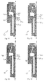
- Figures 2 to 14
- show longitudinal section views of valve assemblies according to further embodiments.
- In the exemplary embodiments and in the figures, identical, similar or similarly acting elements are provided with the same reference symbols. The figures and individual elements in the figures are not to be regarded as true to scale, rather individual elements may be exaggerated in size for better representability or understanding. In addition, in the schematic longitudinal section views of
figure 1B andfigures 2 to 14 , lines which indicate edges that are positioned behind the drawing plane in viewing direction are largely omitted to improve the readability of the figures. In addition, in some figures individual reference symbols may be omitted to improve the clarity of the figures. Specifically, infigures 2 through 14 , most reference symbols which would correspond to those indicated infigure 1B have been omitted. -
Figure 1A shows a longitudinal section view of afluid injection valve 1 according to a first exemplary embodiment. Thefluid injection valve 1 comprises avalve assembly 10.Figure 1B shows a schematic longitudinal section view of thevalve assembly 10 of thefluid injection valve 1 according to the first exemplary embodiment. - The
valve assembly 10 has avalve body 100 which extends along a longitudinal axis L from afluid inlet end 120 to afluid outlet end 130. Thevalve body 10 is in the present embodiment assembled from a plurality of parts. For example, it comprises a fluid inlet tube adjacent to thefluid inlet end 120, a main body, and a one-piecedseat body 135 which is inserted into the main body and fixed thereto at thefluid outlet end 130. - In the present embodiment, the
fluid injection valve 1 is a fuel injection valve which is configured for injecting fuel - such as gasoline - directly into a combustion chamber of an internal combustion engine. - The
valve body 100 has acavity 110 which extends axially through thevalve body 100 for hydraulically connecting thefluid inlet end 120 to thefluid outlet end 130 of the valve body. Thevalve body 100 has avalve seat 140 which is positioned adjacent to thefluid outlet end 130 and, in the present embodiment, is comprised by theseat body 135. - A
valve needle 200 is received in thecavity 110 so that it is movable relative to thevalve body 100 in reciprocating fashion. It is operable to prevent dispensing of fluid from thecavity 110 through an injection nozzle or a plurality of injection nozzles in theseat body 135 by sealingly contacting thevalve seat 140 in the closing position of thevalve needle 200. Thevalve assembly 10 comprises acalibration spring 70, which is arranged in thecavity 110 and preloaded for axially biasing thevalve needle 200 towards the closing position. - Further, the
fluid injection valve 1 has an electromagnetic actuator assembly which comprises anarmature 300, apole piece 50 and acoil 55. Thepole piece 50 and thearmature 300 are positioned in thecavity 110 of thevalve body 100. Thepole piece 50 is positionally fix relative to thevalve body 100, e.g. is press-fitted into thevalve body 100. Thearmature 300 is movable relative to the pole piece and, thus, relative to thevalve body 100 along the longitudinal axis in reciprocating fashion. Thecoil 55 extends circumferentially around a portion of thevalve body 100 and is operable to generate a magnetic field for attracting thearmature 300 in axial direction towards thepole piece 50. - The
armature 300 is mechanically coupled to thevalve needle 200 for displacing thevalve needle 200 axially away from the closing position. More specifically, thevalve needle 200 has a sealingelement 260 at a downstream end 220 of thevalve needle 200. Adjacent to anupstream end 210 of the valve needle, thevalve needle 200 comprises a retainer element 230. Ashaft 240 extends from the retainer element 230 to the sealingelement 260. The retainer element 230 and the sealingelement 260 are fixed to theshaft 240, for example by a welded connection. It is also conceivable that retainer element 230 and/or the sealingelement 260 is in one piece with theshaft 240 instead of being fixed thereto. In the present embodiment, the sealingelement 260 is in the shape of a ball and protrudes radially beyond theshaft 240, at least in the region of the downstream end 220. - The armature extends circumferentially around a portion of the
shaft 240 and is axially displaceable relative to thevalve needle 200. Axial displaceability of thearmature 300 relative to thevalve needle 200 is limited in direction towards theupstream end 210 of thevalve needle 200 by the retainer element 230 and in direction towards the downstream end 220 of thevalve needle 200 by adisc element 250 which is fixed to theshaft 240 of the valve needle on a side of thearmature 300 opposite from the retainer element 230. In other words, thearmature 300 has an axial play relative to thevalve needle 200 which is limited by the retainer element 230 on one side and by thedisc element 250 on the other side. It is also conceivable that thedisc element 250 is in one piece with theshaft 240 instead of being fixed thereto, in particular when the retainer element 230 is not in one piece with theshaft 240. - When the
valve needle 200 is in the closing position and thecoil 55 is activated, thearmature 300 is attracted towards thepole piece 50 and moves in axial direction towards thepole piece 50. It is in form-fit engagement with the retainer element 230 so that it takes thevalve needle 200 with it in direction away from the closing position - i.e. in the present embodiment in direction towards the fluid inlet end 120 - against the bias of thecalibration spring 70. - The sealing
element 260 is in sliding mechanical contact with theseat body 135 for axially guiding the downstream end 220 of thevalve needle 200. Theupstream end 210 of thevalve needle 200 may be axially guided by mechanical interaction between the retainer element 230 and thepole piece 50 or by mechanical interaction of theshaft 240 with thearmature 300 which may in turn in sliding mechanical contact with thevalve body 100 for axially guiding thearmature 300. - In particular, the
seat body 135 is a one-pieced metal part which extends from the main body of thevalve body 100 in radial inward direction so that it is in direct mechanical contact with the sealingelement 260 for establishing the sliding mechanical contact. Fluid passages may be provided between theseat body 135 and the sealingelement 260, for example by means of axial channels in theseat body 135 and/or by means of flat portions of the sealing element. The channels form regions where the sealingelement 260 and theseat body 135 are radially spaced apart from one another so that fluid may axially pass the sealingelement 260 through the channels to thevalve seat 140. - The
cavity 110 has afirst portion 112 and asecond portion 118. Both, thefirst portion 112 and thesecond portion 118 are generally cylindrical in shape, i.e. their circumferential side surfaces have in particular the shape of a circular cylinder. The cross sectional area of thefirst portion 112 is larger than the cross section area of thesecond portion 118. - The
second portion 118 is positioned downstream of thefirst portion 112. More specifically, thefirst portion 112 has abottom surface 114 which in perforated by anopening 116 from which thesecond portion 118 starts and extends in axial direction towards thefluid outlet end 130. In a preferred embodiment, thebottom surface 114 or at least a portion thereof extends perpendicularly to the longitudinal axis L in radial inward direction towards theopening 116. Thus, the inner circumferential surface of thevalve body 100 which defines thecavity 110 has a step. The step comprises thebottom surface 114 and represents an interface between thefirst portion 112 and thesecond portion 118 of thecavity 110. - A
particle retainer element 400 is positioned adjacent to the step. Theparticle retainer element 400 is shown e.g. in the longitudinal section view offigure 1B , where lines are omitted which represent edges of theparticle retainer element 400 being positioned in viewing direction behind the drawing plane offigure 1B . Further, the particle retainer element is shown in two different perspective views infigure 1C and figure 1D . - The
particle retainer element 400 is a one-pieced turned or stamped stainless steel part in the present embodiment. It has aflange portion 410 which is seated on thebottom surface 114, thebottom surface 114 delimiting thefirst portion 112 of thecavity 110 in axial direction towards thefluid outlet end 130. At its radial inward edge, theflange portion 410 merges with a trench portion 220 of theparticle retainer element 400. Thetrench portion 420 thus followsflange portion 410 in radial inward direction. - The trench portion 220 has a U-shaped cross section which is open in axial direction towards the
fluid inlet end 120 and closed in axial direction towards thefluid outlet end 130. In other words, thetrench portion 420 is delimited by side walls in radial inward and outward direction and has a bottom wall which connects the axial ends of the side walls which face towards thefluid outlet end 130. The side walls are preferably in the shape of cylindrical shells and are particularly preferably arranged coaxially to one another and in particular also to the longitudinal axis L. - The outer sidewall of the
trench portion 420 extends from theflange portion 410 in axial direction towards thefluid inlet end 130 into thesecond portion 118 of thecavity 110. It may be in mechanical contact with a circumferential side surface of thesecond portion 118. In one development, a press-fit connection is established between the outer side wall of thetrench portion 420 and thevalve body 100. - The inner side wall of the
trench portion 420 defines acentral aperture 440 of theparticle retainer element 400. The inner side wall extends in axial direction towards thefluid inlet end 120 from thesecond portion 118 of thecavity 110 into thefirst portion 112 and projects in axial direction towards the fluid inlet end beyond theflange portion 410 to a circumferentialinner edge 430 of the inner side wall. Theinner edge 430 is in particular the edge of the inner circumferential side surface of the inner side wall - i.e. the circumfential side surface which faces towards the longitudinal axis - which faces towards thefluid inlet end 120. The circumferentialinner edge 430 is radially offset with respect to an outer contour of theopening 116 in radial inward direction. It defines an outer contour of thecentral aperture 440. - The valve needle extends from the
first portion 112 of thecavity 110 into thesecond portion 118 of the cavity through theopening 116 of thebottom surface 114 and through theaperture 240 of theparticle retainer element 400. The retainer element 230 and thedisc element 250 of the valve needle are positioned within thefirst portion 112 of the cavity, while the sealingelement 260 is positioned in thesecond portion 118 or downstream of thesecond portion 118. The armature 300 - axially sandwiched between the retainer element 230 and the disc element 250 - is also positioned in thefirst portion 112 of thecavity 110. - In the present embodiment, the
shaft 240 of thevalve needle 200 axially overlaps thebottom surface 114, theopening 116 and theparticle retainer element 400, while thedisc element 250, the retainer element 230, and the sealingelement 260 of thevalve needle 200, as well as thearmature 300, have no axial overlap with theparticle retainer element 400, thebottom surface 114 and theopening 116. Thus, theparticle retainer element 400 circumferentially surrounds only theshaft 240 of thevalve needle 200. Theshaft 240 extends axially through theaperture 440. - The fluid injection valve comprises an
additional fluid filter 60 which is press-fitted into a central opening of thepole piece 50 and represents spring seat for thecalibration spring 70. An axial end of thecalibration spring 70 which faces away from thevalve needle 200 is seated against theadditional fluid filter 60. In the present embodiment, an axial end of thecalibration spring 70 which is in mechanical contact with thevalve needle 200 is seated against the retainer element 230. - Fluid is lead through the fluid inlet tube of the
valve body 100 into thecavity 110. It flows through thefluid filter 60, further through the central opening of thepole piece 50 and throughfluid channels 310 which are comprised by thearmature 300. Thefluid channels 310 extend obliquely relative to the longitudinal axis L such that their upstream openings are positioned closer to the longitudinal axis L than their downstream openings. In other words, the radial distance of thefluid channels 310 increases in direction from thefluid inlet end 120 towards thefluid outlet end 130. In this way, thefluid channels 310 direct the fluid flow onto an outer edge region 115 of thebottom surface 114 of thefirst portion 112 of thecavity 110. The outer edge region 115 comprises in particular an interface between thebottom surface 114 and a cylindrical side surface of thefirst portion 112. In this way, fluid is forced to flow radially inward along thebottom surface 114 for entering thesecond portion 118 of thecavity 110 through theopening 116. Due to the circumferentialinner edge 430 of the inner wall of thetrench portion 420 being axially offset relative to theflange portion 410 towards the fluid inlet end, turbulences are created in the region of the trench portion 220 which may cause particles, which are contained in the fluid stream, to settle in the trench portion while the fluid is flowing over the circumferentialinner edge 430 through theaperture 440 of theparticle retainer element 400 to thevalve seat 140 at the fluid outlet end of thevalve body 100. - The
trench portion 420 of theparticle retainer element 400 overlaps theopening 116 of thebottom surface 114 in top view along the longitudinal axis L. The inner side wall of thetrench 420 is laterally spaced apart from theshaft 240 of the valve needle so that theaperture 440 of theparticle retainer element 400 completely overlaps the sealingelement 260 of thevalve needle 200 in top view along the longitudinal axis L. Due to the radial distance between theparticle retainer element 400 and theshaft 240 of the valve body, a fluid passage is established, through which fluid can flow from thefirst portion 112 of the cavity through theaperture 440 of the particle retainer element into thesecond cavity 118 towards thefluid outlet end 130. - The sealing
element 260 has the maximum cross-sectional area of those portions of thevalve needle 200 which axially overlap theparticle retainer element 400 or are axially offset towards thefluid outlet end 130 relative to theparticle retainer element 400, i.e. which are located downstream of the circumferentialinner edge 430. In this way, thevalve needle 200 can be inserted into the valve body and shifted along the longitudinal axis L through the valve body until the sealingelement 260 comes in contact with thevalve seat 140 while theparticle retainer element 400 is already installed in thevalve body 100. When shifting thevalve needle 200 into thevalve body 100, the sealing element passes through theaperture 440 of theparticle retainer element 400 in this case. -
Figure 2 shows avalve assembly 10 according to a second exemplary embodiment in a schematic longitudinal section view corresponding to that offigure 1B . Each of the valve assemblies according to the second embodiment and to the further embodiments below is usable influid injection valves 1 as described in connection with the first embodiment, for example. - The
valve assembly 10 according to the second exemplary embodiment corresponds in general to thevalve assembly 10 of the first embodiment. In particular, theparticle retainer element 400 has aflange portion 410 which bears on thebottom surface 114 and atrench portion 420 extending through theopening 116 of thebottom surface 114 into thesecond portion 118 of thecavity 110. - However, the side walls of the
trench portion 420, optionally also the bottom wall of thetrench portion 420 at its downstream end, and further optionally also theflange portion 410 are provided with a multitude of filteringholes 460 which form a filter sieve for filtering fluid flowing towards thefluid outlet end 130. Each of the filtering holes has a diameter between 20 µm and 30 µm in the present embodiment, the limits being included. With advantage, in case of thevalve assembly 10 of the present embodiment, fluid can also flow through thetrench portion 420 of theparticle retainer element 400 into thesecond portion 118 of thecavity 110 towards thefluid outlet end 130. In this way, fluid flow properties, such as the laminarity of the fluid flow, and the filtering function of the particle retainer element may be particularly advantageous. - Further, contrary to the first embodiment, the
flange portion 410 is pressed onto thebottom surface 114 by anarmature spring 320 which is positioned in thefirst portion 112 of thecavity 110. The armature spring is seated against thearmature 300 and against theflange portion 410 at its opposite axial ends and is preloaded so that it presses theflange portion 410 against thebottom surface 114 and thearmature 300 against the retainer element 230. A press-fit connection between the outer side wall of the trench portion 220 and thevalve body 100 is not necessary in the present embodiment. - The
armature spring 320 is also present in the first embodiment, see in particularfigures 1A and 1B . However, in the first embodiment, thearmature spring 320 is seated against thearmature 300 at one of its axial ends and directly against the valve body 100 - in particular against thebottom surface 114 of thefirst portion 112 of thecavity 110 at the other axial end. Theflange portion 410 is laterally offset in radially inward direction relative to thearmature spring 320. However, it is also conceivable that thearmature spring 320 is seated against theflange portion 410 for the first embodiment or other embodiments of the present invention. -
Figure 3 shows avalve assembly 10 according to a third exemplary embodiment in a schematic longitudinal section view corresponding to that offigure 2 . - The
valve assembly 10 according to a third exemplary embodiment corresponds in general to that of the second exemplary embodiment. However, the axial dimension of thetrench portion 420 is reduced. While the axial dimension of thetrench portion 420 in the first and second embodiments is at least 50% of the axial dimension of thesecond portion 118 and in particular at least 50% of the distance between theopening 116 and thevalve seat 140, thetrench portion 420 of theparticle retainer element 400 of the third exemplary embodiment has a value of, for example, between 10% and 20% of the axial dimension of thesecond portion 118, the limits being included. - However, the circumferential
inner edge 430 is axially positioned closer to thefluid inlet end 120 as compared to the second and first exemplary embodiments. In particular, the circumferentialinner edge 430 of theparticle retainer element 400 axially overlaps thedisc element 250 which limits the axial displaceability of thearmature 300 relative to thevalve needle 200. The circumferentialinner edge 430 also laterally overlaps thedisc element 250 in this embodiment - analogously to the previous embodiments. Due to the lateral and axial overlap in the present embodiment, a particularly large portion of the fluid flow is guided through the filter sieve formed by the filtering holes 460 of theparticle retainer element 400. -
Figure 4 shows avalve assembly 10 according to a fourth exemplary embodiment in a schematic longitudinal section view, corresponding to that offigure 3 . - The
particle retainer element 400 according to the fourth exemplary embodiment corresponds general to that of the third exemplary embodiment. However, while theparticle retainer element 400 of the third exemplary embodiment is perforated by filteringholes 460 everywhere, theflange portion 410 and anupper section 425 of the inner wall of thetrench portion 420 are unperforated by filteringholes 460. - The
upper section 425 of the inner wall comprises the innercircumferential edge 430 and extends downstream from the innercircumferential edge 430 towards the opening 116 of thebottom surface 114. Preferably, theupper section 425 is axially offset with respect to theopening 116 towards thefluid inlet end 120 or axially flush with respect to theopening 116. - At least a portion of the inner wall of the
trench portion 420 which follows theupper section 425 in direction towards thefluid outlet end 130 is perforated by filteringholes 460 to form a filter sieve. In the present embodiment, also the bottom wall of thetrench portion 420 is perforated by filteringholes 460. The outer wall may or may not be perforated by filteringholes 460. - In this way, the fluid stream is particularly well guided through the
trench portion 420. This embodiment makes use of the idea that the preferably smooth surface of theunperforated flange portion 410 may lead the fluid particularly well in radial inward direction and/or the unperforatedupper section 425 of the inner wall has a particularly large hydraulic resistance and my contribute to deflecting the fluid stream into thetrench portion 420. -
Figure 5 shows avalve assembly 10 according to a fifth exemplary embodiment in a schematic longitudinal section view corresponding to that offigure 3 . Thevalve assembly 10 according to a fifth exemplary embodiment corresponds in general to that of the third exemplary embodiment. - However, in contrast to the third exemplary embodiment, the
particle retainer element 400 has an outercylindrical side wall 415 which merges with an outer lateral edge of theflange portion 410 from there it extends in axial direction towards thefluid inlet end 120. Thearmature spring 420 is laterally offset in radial inward direction from the outercylindrical side wall 415, for example. In one development, a press-fit connection and/or a welded connection is established between thevalve body 100 and the outercylindrical side wall 415. -
Figure 6 shows avalve assembly 10 according to a sixth exemplary embodiment in a schematic longitudinal section view corresponding to that offigure 3 . Thevalve assembly 10 of the sixth embodiment corresponds in general to that of the third exemplary embodiment. - In particular, the
particle retainer element 400 of the sixth embodiment corresponds in general to that of the third exemplary embodiment. In contrast thereto, however, it does not have atrench portion 420 which extends through theopening 116 and abottom surface 114 into thesecond portion 118 of thecavity 110. Instead, theparticle retainer element 400 has an L-shaped cross section, extending radially inward from theflange portion 410 which bears on thebottom surface 114 and subsequently extends axially towards thefluid inlet end 120 to the circumferentialinner edge 430. In the present embodiment, theparticle retainer element 400 is positioned within thefirst portion 112 of thecavity 110 in its entirety and partially covers theopening 116 in thebottom surface 114. - In other words, the particle retainer element consists of a ring-shaped portion comprising the
flange portion 410, the ring-shaped portion extending around the longitudinal axis L, being in mechanical contact with thebottom surface 114 and partially overlapping theopening 116. At an inner circumferential edge of the ring portion, a cylindrical inner wall merges with the inner edge and extends in axial direction towards thefluid inlet end 120 to the circumferentialinner edge 430 to define theaperture 440. - In the context of this embodiment and further embodiments below, a "ring-shaped portion" of the
particle retainer element 400 is in particular understood to mean a perforated disc shaped portion. A perforated disc is in particular understood to mean a cylindrical shell having a height which is smaller than its outer diameter; for example the height is 50 % or less, preferably 20 % or less, of the outer diameter. The perforated disc has its central axis in particular parallel or - preferably - coaxial to the longitudinal axis L. Main surfaces of the perforated disk extend preferably perpendicular to the longitudinal axis and face towards thefluid inlet end 120 and towards thefluid outlet end 130, respectively. The ring-shaped portion may be perforated by filteringholes 460. In this case, the filtering holes 460 preferably extend through the ring-shaped portion in axial direction. -
Figure 7 shows avalve assembly 10 according to a seventh embodiment in a schematic longitudinal section view corresponding to that offigure 6 . Thevalve assembly 10 according to the eighth embodiment corresponds in general to that of the sixth embodiment. - However, the circumferential
inner edge 430 is axially offset towards thefluid outlet end 130 relative to thedisc element 250 of thevalve needle 250 and only laterally overlaps thedisc element 250 in the sixth embodiment- as in the first and second embodiments, for example. In contrast thereto, the circumferentialinner edge 430 axially and laterally overlaps thedisc element 250 in the seventh embodiment, for example as in the third embodiment. -
Figure 8 shows avalve assembly 10 according to an eighth embodiment in a schematic longitudinal section view corresponding to that offigure 7 . Thevalve assembly 10 according to the eighth embodiment corresponds in general to that of the seventh embodiment. - However, instead of an L-shaped cross section, it has two concentric ring-shaped portions which are axially displaced with respect to one another and are connected by a conical portion. Specifically, the
flange portion 410 represents a first ring-shaped portion. It is succeeded in radial inward direction by a conical portion. The conical portion tapers from a first edge in axial direction towards thefluid inlet end 120 to a second circumferential edge. At the first edge, the conical portion merges with theflange portion 410. At the second edge, the conical portion merges with a second ring-shaped portion. The second ring-shaped portion follows the conical portion in radial inward direction and extends to the circumferentialinner edge 430. The second ring-shaped portion axially and laterally overlaps thedisc element 250 of thevalve needle 200. -
Figure 9 shows avalve assembly 10 according to a ninth exemplary embodiment in a schematic longitudinal section view corresponding to that offigure 7 . The valve assembly according to the ninth exemplary embodiment corresponds in general to that of the seventh exemplary embodiment. - However, instead of having a cylindrical inner wall which defines the
aperture 440, the inner wall is shaped to form two axially subsequent pockets. To this end, it has an S-shaped or Z-shaped cross section, for example. Specifically, an upstream surface 401 of theparticle retainer element 400 extends, in the course from theflange portion 410 to the circumferentialinner edge 430, in radial inward direction, subsequently in axial direction towards thefluid inlet end 120 and subsequently in radial outward direction so as to form a firstcircumferential pocket 450 for accommodating particles. - In the present embodiment, the first
circumferential pocket 450 is formed by a first ring-shaped portion, a first cylindrical wall portion, and a second ring-shaped portion of theparticle retainer element 400. The first ring-shaped portion comprises theflange portion 410 and extends radially inwards so as to cover theopening 116 partially. The first cylindrical wall portion merges with the first ring-shaped portion at one axial end and merges with an inner circumferential end of the second ring-shaped portion at the opposite axial end. The second ring-shaped portion extends radially outward from its inner circumferential end so that it laterally overlaps the first ring-shaped portion. - In the present embodiment, the particle retainer element further comprises a second cylindrical wall portion, merging with an outer lateral edge of the second ring-shaped portion at one axial end and with the outer lateral edge of a third ring-shaped portion at its opposite axial end. The third ring-shaped portion comprises the circumferential inner edge on its lateral side remote from the outer lateral edge. By means of the second and third ring-shaped portions and the second cylindrical wall portion, a second circumferential pocket is formed in the
particle retainer element 400 which is open at its side facing towards the longitudinal axis L. - All central axes of the ring-shaped portions and the cylindrical wall portions are preferably coaxial to the longitudinal axes. The third ring-shaped portion axially and laterally overlaps the
disc element 250 of thevalve needle 200. In addition, the second cylindrical wall portion overlaps thedisc element 250 at least axially. -
Figure 10 shows avalve assembly 10 according to a tenth exemplary embodiment in a schematic longitudinal section view corresponding in general to that offigure 8 . - The
valve assembly 10 according to the tenth embodiment corresponds in general to that of the eighth embodiment. However, in the present embodiment, theparticle retainer element 400 is in direct mechanical contact with thedisc element 250 of thevalve needle 200. - More specifically, in the present embodiment the
particle retainer element 400 has a first ring-shaped portion comprising theflange portion 410, a conical portion and a second ring-shaped portion as described above in connection with the eighth embodiment. In addition, however, theparticle retainer element 400 has a cylindrical wall portion merging with an inner circumferential edge of the second ring-shaped portion and extending in axial direction towards thefluid inlet end 120 from said edge to thedisc element 250 where it comprises the circumferentialinner edge 430 of theparticle retainer element 400. The cylindrical wall portion, in particular the circumferentialinner edge 430, contacts a surface of thedisc element 250 of thevalve needle 200 which surface faces towards thefluid outlet end 130. - In the present embodiment, the
particle retainer element 400 also has an outercylindrical sidewall 415 as described above in connection with the fifth embodiment. -
Figure 11 shows avalve assembly 10 according to an eleventh embodiment in a schematic longitudinal section view corresponding to that offigure 3 . Thevalve assembly 10 according to the eleventh embodiment corresponds in general to that of the third embodiment. - However, in the present embodiment the
particle retainer element 400 is not laterally spaced apart from theshaft 240 of thevalve needle 200. Rather, thetrench portion 420 bridges the entire radial clearance between thevalve body 100 and theshaft 240. The circumferential inner wall of thetrench 420 which comprises the circumferentialinner edge 430 of theparticle retainer element 400 is in direct mechanical contact with theshaft 240 of thevalve needle 200. More specifically, the inner wall of thetrench portion 420 is in sliding mechanical contact with theshaft 240 and theparticle retainer element 400 has an axial play relative to thevalve needle 200. - Axial displaceability of the
particle retainer element 400 relative to thevalve needle 200 is limited in the present embodiments by lockingelements 270, such as circlips, snap rings, or the like. The lockingelement 270 are positioned axially subsequent to the inner wall of thetrench portion 420 in axial direction towards thefluid inlet end 120 and towards thefluid outlet end 130. The lockingelements 270 are positionally fix relative to theshaft 240 of the valve needle. For example, they are in form-fit end and/or force-fit engagement with respective grooves in theshaft 240. In this way, axial displaceability of the inner wall and, thus, of the circumferentialinner edge 430 relative to theshaft 240 is limited. - The
particle retainer element 400 may be operable to engage in form-fit connection with the lockingelements 270. In this way, axial displacement of theparticle retainer element 400 relative to thevalve needle 200 can be limited before and during inserting thevalve needle 200 into thevalve body 100 together with theparticle retainer element 400 when assembling thevalve assembly 10. - During operation of the
valve assembly 10, the inner wall of thetrench portion 420 is preferably spaced apart from the lockingelements 270 when thevalve needle 200 is in the closing position as well as in a fully open configuration of thevalve assembly 10 in which thearmature 300 and/or the retainer element 230 are preferably in form-fit connection with thevalve body 100 or thepole piece 50. To hold theparticle retainer element 400 in place, theflange portion 410 of theparticle retainer element 400 is pressed against thebottom surface 114 which delimits thefirst portion 112 of thecavity 110 by means of thearmature spring 320 as described above, e.g. in connection with the third embodiment. -
Figure 12 shows avalve assembly 10 according to a twelfth exemplary embodiment in a schematic longitudinal section view corresponding to that offigure 11 . Thevalve assembly 10 according to the twelfth embodiment corresponds in general to thevalve assembly 10 according to the eleventh embodiment. In contrast thereto, thetrench portion 420 has an outer circumferential side wall which is not cylindrical in shape but tapers conically in axial direction towards thefluid outlet end 130. -
Figure 13 shows avalve assembly 10 according to a thirteenth embodiment in a schematic longitudinal section view corresponding to that offigure 11 . Thevalve assembly 10 according to the thirteenth embodiment corresponds in general to that of the eleventh embodiment. - However, the
particle retainer element 400 of the present embodiment does not have atrench portion 420 which extends in axial direction towards thefluid outlet end 130 into thesecond portion 118 of thecavity 110. Instead, theflange portion 410 is followed in radial inward direction by a cylindrical wall portion which extends from thebottom surface 114 in axial direction towards thefluid inlet end 120 into thefirst portion 112 and is followed in radial inward direction by a ring-shaped portion which bridges theopening 116 and extends in radial inward direction to theshaft 240 of the valve needle where it comprises the circumferentialinner edge 430. A circumferential inner wall extends in axial direction towards the fluid outlet end 130 from the circumferentialinner edge 430 and is positioned axially between two lockingelements 270 as in the eleventh embodiment. In this way, the installation of thevalve needle 200, preassembled with theparticle retainer element 400, into thevalve body 100 is particularly simple and does in particular not require shifting thetrench portion 420 of theparticle retainer element 400 into thesecond portion 118 of thecavity 110 through theopening 116. -
Figure 14 shows avalve assembly 10 according to a fourteenth embodiment in a schematic longitudinal section view corresponding to that offigure 13 . Thevalve assembly 10 according to the fourteenth embodiment corresponds in general to that of the thirteenth embodiment. In contrast thereto, theparticle retainer element 400 has a conical portion instead of the cylindrical wall portion between theflange portion 410 and the ring-shaped portion. The conical portion tapers in axial direction towards thefluid inlet end 120. - The invention is not limited to specific embodiments by the description on basis of these exemplary embodiments. Rather, it comprises any combination of elements of different embodiments. Moreover, the invention comprises any combination of claims and any combination of features disclosed by the claims.
Claims (14)
- Valve assembly (10) for a fluid injection valve (1) comprising- a valve body (100) having a longitudinal axis (L), having a cavity (110) which extends axially through the valve body (100) for hydraulically connecting a fluid inlet end (120) to a fluid outlet end (130) of the valve body, and having a valve seat (140) adjacent to the fluid outlet end (130);- a valve needle (200) movably received in the cavity (110) and operable to sealingly contact the valve seat (140) in a closing position of the valve needle (200); and- an armature (300) being configured and movably arranged in the cavity (110) for displacing the valve needle (200) axially away from the closing position,
wherein- the cavity (110) has a first portion (112) accomodating the armature (300) and being limited in axial direction towards the fluid outlet end (130) by a bottom surface (114),- the bottom surface (114) has a central opening (116) from which a second portion (118) of the cavity (110) extends towards the fluid outlet end (130);- a shaft (240) of the valve needle (200) extends through the opening (116) into the second portion (118); and- a particle retainer element (400) is positioned in the cavity (110) such that it bears on the bottom surface (114), circumferentially surrounds the shaft (240) of the valve needle (200) and overlaps with the opening (116). - Valve assembly (10) according to the preceding claim, comprising fluid channels (310) which are operable to guide fluid towards an outer edge region (115) of the bottom surface (114), the fluid channels (310) either being comprised by the armature (300) and extending obliquely to the longitudinal axis (L) being or the fluid channels being formed between an outer circumferential surface of the armature (300) and the valve body (100).
- Valve assembly (10) according to one of the preceding claims, wherein- the particle retainer element (400) has a flange portion (410) and a circumferential inner edge (430),- the flange portion (410) bears on the bottom surface (114);- the circumferential inner edge (430) is radially offset with respect to an outer contour of the opening (116) of the bottom surface (114) in radial inward direction and defines a central aperture (440) of the particle retainer element (400); and- the shaft (240) of the valve needle (200) extends axially through the aperture (440).
- Valve assembly (10) according to the preceding claim, wherein the particle retainer element (400) comprises a trench portion (420) for accommodating particles, wherein the trench portion (420) follows the flange portion (410) in radial inward direction and extends axially into the second portion (118) of the cavity (110).
- Valve assembly (10) according to one of the preceding claims 3 to 4, wherein an upstream surface (401) of the particle retainer element (400) extends, in the course from the flange portion (410) to the circumferential inner edge (430), in radial inward direction, subsequently in axial direction towards the fluid inlet end (120) and subsequently in radial outward direction so as to form a circumferential pocket (450) for accommodating particles.
- Valve assembly (10) according to one of the preceding claims 3 to 5, wherein the circumferential inner edge (430) is positioned in the first portion (112) of the cavity (100), axially offset towards the fluid inlet end (120) relative to the bottom surface (114) and in particular to the flange portion (410).
- Valve assembly (10) according to one of the preceding claims 3 to 6, wherein the cross-sectional area of the aperture (440) is larger than a maximum cross-sectional area of that portion of the valve needle (200) which is positioned downstream of the circumferential inner edge (430).
- Valve assembly (10) according to one of the preceding claims 3 to 6, wherein the circumferential inner edge (430) is in mechanical contact with the shaft (240) of the valve needle (200) or with a disc element (250) of the valve needle (200) which extends circumferentially around the shaft (240).
- Valve assembly (10) according to the preceding claim, wherein the particle retainer element (400) is in a form-fit connection or operable to engage in a form-fit connection with the valve needle (200) for limiting axial displacement of the circumferential inner edge (430) relative to the shaft (240).
- Valve assembly (10) according to one of the preceding claims, further comprising an armature spring (320) which is seated against the armature (300) and against the particle retainer element (400) at opposite axial ends and which is preloaded to press the particle retainer element (400) in contact with the bottom surface (114).
- Valve assembly (10) according to one of the preceding claims, wherein the particle retainer element (400) is a one-pieced metal part.
- Valve assembly (10) according to one of the preceding claims, wherein the particle retainer element (400) has a multitude of filtering holes (460), in particular each having a diameter of 100 µm or less, which form a filter sieve.
- Fluid injection valve (1) comprising a valve assembly (10) according to one of the preceding claims and an additional fluid filter (70) upstream of the armature (300).
- Fluid injection valve (1) according to the preceding claim, wherein the valve body (100) comprises a seat body (135) which comprises the valve seat (140) and is in particular a one-pieced part and the valve needle comprises a sealing element (260) which is in mechanical contact with the valve seat (140) in the closing position of the valve needle (200), the sealing element (260) being in sliding mechanical contact with the seat body (135) for axially guiding the valve needle (200).
Priority Applications (4)
| Application Number | Priority Date | Filing Date | Title |
|---|---|---|---|
| EP15162310.5A EP3076004B1 (en) | 2015-04-02 | 2015-04-02 | Valve assembly with a particle retainer element and fluid injection valve |
| KR1020160040368A KR101933757B1 (en) | 2015-04-02 | 2016-04-01 | Valve assembly with a particle retainer element and fluid injection valve |
| US15/089,949 US9982641B2 (en) | 2015-04-02 | 2016-04-04 | Valve assembly with a particle retainer element and fluid injection valve |
| CN201610205022.0A CN106050508B (en) | 2015-04-02 | 2016-04-05 | Valve assembly with particle retainer element and fluid injection valve |
Applications Claiming Priority (1)
| Application Number | Priority Date | Filing Date | Title |
|---|---|---|---|
| EP15162310.5A EP3076004B1 (en) | 2015-04-02 | 2015-04-02 | Valve assembly with a particle retainer element and fluid injection valve |
Publications (2)
| Publication Number | Publication Date |
|---|---|
| EP3076004A1 true EP3076004A1 (en) | 2016-10-05 |
| EP3076004B1 EP3076004B1 (en) | 2018-09-12 |
Family
ID=52807693
Family Applications (1)
| Application Number | Title | Priority Date | Filing Date |
|---|---|---|---|
| EP15162310.5A Active EP3076004B1 (en) | 2015-04-02 | 2015-04-02 | Valve assembly with a particle retainer element and fluid injection valve |
Country Status (4)
| Country | Link |
|---|---|
| US (1) | US9982641B2 (en) |
| EP (1) | EP3076004B1 (en) |
| KR (1) | KR101933757B1 (en) |
| CN (1) | CN106050508B (en) |
Cited By (1)
| Publication number | Priority date | Publication date | Assignee | Title |
|---|---|---|---|---|
| EP3467299A1 (en) * | 2017-10-06 | 2019-04-10 | Continental Automotive GmbH | Valve assembly for an injection valve and injection valve |
Families Citing this family (1)
| Publication number | Priority date | Publication date | Assignee | Title |
|---|---|---|---|---|
| EP2940286A1 (en) * | 2014-05-01 | 2015-11-04 | Delphi International Operations Luxembourg S.à r.l. | Fuel injector filter |
Citations (4)
| Publication number | Priority date | Publication date | Assignee | Title |
|---|---|---|---|---|
| EP0697064A1 (en) | 1993-05-03 | 1996-02-21 | Siemens Automotive Corporation | Filter cartridge mounting for a top-feed fuel injector |
| EP1118767A2 (en) * | 2000-01-19 | 2001-07-25 | Visteon Global Technologies, Inc. | A combined needle guide, filter, and flow director for gasoline fuel injectors |
| EP2060777A1 (en) | 2007-11-13 | 2009-05-20 | Delphi Technologies, Inc. | Internal lower fuel injector filter |
| US20110006136A1 (en) * | 2009-07-07 | 2011-01-13 | Flynn Vicki A | Lower Fuel Injector Filter |
Family Cites Families (39)
| Publication number | Priority date | Publication date | Assignee | Title |
|---|---|---|---|---|
| WO1993018299A1 (en) * | 1992-03-05 | 1993-09-16 | Siemens Automotive L.P. | Fuel injector having an internal filter |
| DE4325842A1 (en) * | 1993-07-31 | 1995-02-02 | Bosch Gmbh Robert | Fuel injection valve |
| US5755386A (en) * | 1995-12-26 | 1998-05-26 | General Motors Corporation | Fuel injector deep drawn valve guide |
| US5678767A (en) * | 1996-03-14 | 1997-10-21 | Siemens Automotive Corporation | Fuel injector with contaminant deflector |
| DE19631066A1 (en) * | 1996-08-01 | 1998-02-05 | Bosch Gmbh Robert | Fuel injector |
| DE19638201B4 (en) * | 1996-09-19 | 2005-05-04 | Robert Bosch Gmbh | Fuel injector |
| US6015103A (en) * | 1998-06-08 | 2000-01-18 | General Motors Corporation | Filter for fuel injector |
| US5967424A (en) * | 1998-06-24 | 1999-10-19 | General Motors Corporation | Fuel injector filter |
| DE19927899A1 (en) * | 1999-06-18 | 2000-12-21 | Bosch Gmbh Robert | Fuel injection valve for fuel injection device for IC engine has guide disc infront of valve seat provided with opening having alternating guide regions for valve closure element and fuel flow regions |
| DE19927900A1 (en) * | 1999-06-18 | 2000-12-21 | Bosch Gmbh Robert | Fuel injection valve for direct injection IC engine has movement of armature limited by opposing stops attached to valve needle one of which is provided by spring element |
| US6405947B2 (en) * | 1999-08-10 | 2002-06-18 | Siemens Automotive Corporation | Gaseous fuel injector having low restriction seat for valve needle |
| DE10004960A1 (en) | 2000-02-04 | 2001-08-09 | Bosch Gmbh Robert | Fuel injection valve for IC engine fuel injection system has 2 magnetic coils providing opening and closing forces acting on 2 magnetic armatures |
| DE10038098A1 (en) * | 2000-08-04 | 2002-02-14 | Bosch Gmbh Robert | Fuel injector |
| DE10043085A1 (en) * | 2000-09-01 | 2002-03-14 | Bosch Gmbh Robert | Fuel injector |
| US6604695B1 (en) * | 2000-09-25 | 2003-08-12 | Siemens Automotive Corporation | Method and fuel injector for setting gaseous injector static flow rate with injector stroke |
| DE10052485B4 (en) * | 2000-10-23 | 2005-12-08 | Robert Bosch Gmbh | Fuel injector |
| DE10059420A1 (en) * | 2000-11-30 | 2002-06-06 | Bosch Gmbh Robert | Fuel injector |
| DE10060290A1 (en) * | 2000-12-05 | 2002-06-06 | Bosch Gmbh Robert | Fuel injector |
| DE10124743A1 (en) * | 2001-05-21 | 2002-11-28 | Bosch Gmbh Robert | Fuel injection valve for an internal combustion engine comprises an armature having an armature buffer sleeve inserted in a form-locking manner into an inner recess of an armature casing |
| DE10130205A1 (en) * | 2001-06-22 | 2003-01-02 | Bosch Gmbh Robert | Fuel injector |
| US20030234004A1 (en) * | 2002-06-21 | 2003-12-25 | Forgue John R. | No-return loop fuel system |
| DE10334785A1 (en) * | 2003-07-30 | 2005-02-24 | Robert Bosch Gmbh | Fuel injection valve and method for its assembly |
| US7258281B2 (en) * | 2003-12-19 | 2007-08-21 | Siemens Vdo Automotive Corporation | Fuel injector with a metering assembly having a polymeric support member which has an external surface secured to a bore of a polymeric housing and a guide member that is disposed in the polymeric support member |
| DE102004010174B4 (en) * | 2004-03-02 | 2017-04-06 | Robert Bosch Gmbh | Pressing composite of a metal part and a plastic part |
| JP2006017101A (en) * | 2004-06-02 | 2006-01-19 | Denso Corp | Fuel injection valve |
| JP3944497B2 (en) * | 2004-07-15 | 2007-07-11 | 三菱電機株式会社 | Fuel injection valve |
| US7617991B2 (en) * | 2006-03-31 | 2009-11-17 | Delphi Technologies, Inc. | Injector fuel filter with built-in orifice for flow restriction |
| JP4211814B2 (en) * | 2006-07-13 | 2009-01-21 | 株式会社日立製作所 | Electromagnetic fuel injection valve |
| JP4887369B2 (en) * | 2006-09-25 | 2012-02-29 | 日立オートモティブシステムズ株式会社 | Fuel injection valve |
| US20090236448A1 (en) * | 2008-03-18 | 2009-09-24 | Kimberly Burkhard | Fuel injector lower filter |
| US20090256009A1 (en) | 2008-04-10 | 2009-10-15 | Perry Robert B | Protection device for a lower guide system of a fuel injector |
| JP5965253B2 (en) * | 2012-02-20 | 2016-08-03 | 株式会社デンソー | Fuel injection valve |
| KR20150006044A (en) * | 2012-05-08 | 2015-01-15 | 콘티넨탈 오토모티브 게엠베하 | Valve assembly for an injection valve and injection valve |
| JP5955198B2 (en) * | 2012-11-02 | 2016-07-20 | 株式会社ケーヒン | Support structure for direct injection fuel injection valve |
| JP6035648B2 (en) * | 2012-11-05 | 2016-11-30 | 株式会社ケーヒン | Electromagnetic fuel injection valve |
| EP2811152B1 (en) * | 2013-06-04 | 2018-04-18 | Continental Automotive GmbH | Filter for a fluid injection valve, fluid injection valve and method for producing a filter for a fluid injection valve |
| JP6135362B2 (en) * | 2013-07-25 | 2017-05-31 | 株式会社デンソー | Fuel injection valve |
| EP2896816A1 (en) * | 2014-01-16 | 2015-07-22 | Continental Automotive GmbH | Filter assembly for a fuel injector, fuel injector and method for assembly the filter assembly |
| EP2949917B1 (en) * | 2014-05-27 | 2017-01-04 | Continental Automotive GmbH | Fuel injector |
-
2015
- 2015-04-02 EP EP15162310.5A patent/EP3076004B1/en active Active
-
2016
- 2016-04-01 KR KR1020160040368A patent/KR101933757B1/en active Active
- 2016-04-04 US US15/089,949 patent/US9982641B2/en active Active
- 2016-04-05 CN CN201610205022.0A patent/CN106050508B/en active Active
Patent Citations (4)
| Publication number | Priority date | Publication date | Assignee | Title |
|---|---|---|---|---|
| EP0697064A1 (en) | 1993-05-03 | 1996-02-21 | Siemens Automotive Corporation | Filter cartridge mounting for a top-feed fuel injector |
| EP1118767A2 (en) * | 2000-01-19 | 2001-07-25 | Visteon Global Technologies, Inc. | A combined needle guide, filter, and flow director for gasoline fuel injectors |
| EP2060777A1 (en) | 2007-11-13 | 2009-05-20 | Delphi Technologies, Inc. | Internal lower fuel injector filter |
| US20110006136A1 (en) * | 2009-07-07 | 2011-01-13 | Flynn Vicki A | Lower Fuel Injector Filter |
Cited By (2)
| Publication number | Priority date | Publication date | Assignee | Title |
|---|---|---|---|---|
| EP3467299A1 (en) * | 2017-10-06 | 2019-04-10 | Continental Automotive GmbH | Valve assembly for an injection valve and injection valve |
| WO2019068573A1 (en) * | 2017-10-06 | 2019-04-11 | Continental Automotive Gmbh | Valve assembly for an injection valve and injection valve |
Also Published As
| Publication number | Publication date |
|---|---|
| US9982641B2 (en) | 2018-05-29 |
| KR20160118983A (en) | 2016-10-12 |
| KR101933757B1 (en) | 2018-12-28 |
| CN106050508B (en) | 2020-03-20 |
| US20160290295A1 (en) | 2016-10-06 |
| CN106050508A (en) | 2016-10-26 |
| EP3076004B1 (en) | 2018-09-12 |
Similar Documents
| Publication | Publication Date | Title |
|---|---|---|
| US9951735B2 (en) | Filter for a fluid injection valve, fluid injection valve and method for producing a filter for a fluid injection valve | |
| JP3969247B2 (en) | Fuel injection valve | |
| KR101029214B1 (en) | Fuel injector | |
| EP3076004B1 (en) | Valve assembly with a particle retainer element and fluid injection valve | |
| EP2811151A1 (en) | Filter for a fuel injection valve, fuel injection valve and method for producing a filter for a fuel injection valve | |
| US9863383B2 (en) | Valve assembly with a guide element | |
| US20240125292A1 (en) | Injector with integrated filter | |
| EP2743491A1 (en) | Valve body, fluid injection valve and method for producing a valve body | |
| CN105283664A (en) | Fuel injection valve | |
| US6889708B2 (en) | Valve comprising a filter | |
| EP3279462B1 (en) | Filter assembly for an injection valve, valve assembly and injection valve | |
| EP3037650B1 (en) | Valve assembly and fluid injection valve | |
| EP3467299B1 (en) | Valve assembly for an injection valve and injection valve | |
| CN100535431C (en) | Fuel ejecting valve | |
| EP3344869B1 (en) | Injector for a combustion engine | |
| EP3156638A1 (en) | Fuel injector | |
| EP2933472A1 (en) | Fuel injection valve for an internal combustion engine | |
| WO2025087993A1 (en) | Fuel injector assembly | |
| JP2022053503A (en) | Injector incorporated with filter and method for assembling injector |
Legal Events
| Date | Code | Title | Description |
|---|---|---|---|
| PUAI | Public reference made under article 153(3) epc to a published international application that has entered the european phase |
Free format text: ORIGINAL CODE: 0009012 |
|
| AK | Designated contracting states |
Kind code of ref document: A1 Designated state(s): AL AT BE BG CH CY CZ DE DK EE ES FI FR GB GR HR HU IE IS IT LI LT LU LV MC MK MT NL NO PL PT RO RS SE SI SK SM TR |
|
| AX | Request for extension of the european patent |
Extension state: BA ME |
|
| STAA | Information on the status of an ep patent application or granted ep patent |
Free format text: STATUS: REQUEST FOR EXAMINATION WAS MADE |
|
| 17P | Request for examination filed |
Effective date: 20170405 |
|
| RBV | Designated contracting states (corrected) |
Designated state(s): AL AT BE BG CH CY CZ DE DK EE ES FI FR GB GR HR HU IE IS IT LI LT LU LV MC MK MT NL NO PL PT RO RS SE SI SK SM TR |
|
| RIC1 | Information provided on ipc code assigned before grant |
Ipc: F16K 31/06 20060101ALI20180208BHEP Ipc: F02M 51/06 20060101ALI20180208BHEP Ipc: F16K 1/12 20060101ALI20180208BHEP Ipc: F02M 61/16 20060101AFI20180208BHEP |
|
| GRAP | Despatch of communication of intention to grant a patent |
Free format text: ORIGINAL CODE: EPIDOSNIGR1 |
|
| STAA | Information on the status of an ep patent application or granted ep patent |
Free format text: STATUS: GRANT OF PATENT IS INTENDED |
|
| INTG | Intention to grant announced |
Effective date: 20180321 |
|
| GRAS | Grant fee paid |
Free format text: ORIGINAL CODE: EPIDOSNIGR3 |
|
| GRAA | (expected) grant |
Free format text: ORIGINAL CODE: 0009210 |
|
| STAA | Information on the status of an ep patent application or granted ep patent |
Free format text: STATUS: THE PATENT HAS BEEN GRANTED |
|
| AK | Designated contracting states |
Kind code of ref document: B1 Designated state(s): AL AT BE BG CH CY CZ DE DK EE ES FI FR GB GR HR HU IE IS IT LI LT LU LV MC MK MT NL NO PL PT RO RS SE SI SK SM TR |
|
| REG | Reference to a national code |
Ref country code: GB Ref legal event code: FG4D |
|
| REG | Reference to a national code |
Ref country code: CH Ref legal event code: EP |
|
| REG | Reference to a national code |
Ref country code: IE Ref legal event code: FG4D |
|
| REG | Reference to a national code |
Ref country code: DE Ref legal event code: R096 Ref document number: 602015015945 Country of ref document: DE |
|
| REG | Reference to a national code |
Ref country code: AT Ref legal event code: REF Ref document number: 1040890 Country of ref document: AT Kind code of ref document: T Effective date: 20181015 |
|
| REG | Reference to a national code |
Ref country code: NL Ref legal event code: MP Effective date: 20180912 |
|
| REG | Reference to a national code |
Ref country code: LT Ref legal event code: MG4D |
|
| PG25 | Lapsed in a contracting state [announced via postgrant information from national office to epo] |
Ref country code: SE Free format text: LAPSE BECAUSE OF FAILURE TO SUBMIT A TRANSLATION OF THE DESCRIPTION OR TO PAY THE FEE WITHIN THE PRESCRIBED TIME-LIMIT Effective date: 20180912 Ref country code: LT Free format text: LAPSE BECAUSE OF FAILURE TO SUBMIT A TRANSLATION OF THE DESCRIPTION OR TO PAY THE FEE WITHIN THE PRESCRIBED TIME-LIMIT Effective date: 20180912 Ref country code: RS Free format text: LAPSE BECAUSE OF FAILURE TO SUBMIT A TRANSLATION OF THE DESCRIPTION OR TO PAY THE FEE WITHIN THE PRESCRIBED TIME-LIMIT Effective date: 20180912 Ref country code: FI Free format text: LAPSE BECAUSE OF FAILURE TO SUBMIT A TRANSLATION OF THE DESCRIPTION OR TO PAY THE FEE WITHIN THE PRESCRIBED TIME-LIMIT Effective date: 20180912 Ref country code: NO Free format text: LAPSE BECAUSE OF FAILURE TO SUBMIT A TRANSLATION OF THE DESCRIPTION OR TO PAY THE FEE WITHIN THE PRESCRIBED TIME-LIMIT Effective date: 20181212 Ref country code: BG Free format text: LAPSE BECAUSE OF FAILURE TO SUBMIT A TRANSLATION OF THE DESCRIPTION OR TO PAY THE FEE WITHIN THE PRESCRIBED TIME-LIMIT Effective date: 20181212 Ref country code: GR Free format text: LAPSE BECAUSE OF FAILURE TO SUBMIT A TRANSLATION OF THE DESCRIPTION OR TO PAY THE FEE WITHIN THE PRESCRIBED TIME-LIMIT Effective date: 20181213 |
|
| PG25 | Lapsed in a contracting state [announced via postgrant information from national office to epo] |
Ref country code: AL Free format text: LAPSE BECAUSE OF FAILURE TO SUBMIT A TRANSLATION OF THE DESCRIPTION OR TO PAY THE FEE WITHIN THE PRESCRIBED TIME-LIMIT Effective date: 20180912 Ref country code: HR Free format text: LAPSE BECAUSE OF FAILURE TO SUBMIT A TRANSLATION OF THE DESCRIPTION OR TO PAY THE FEE WITHIN THE PRESCRIBED TIME-LIMIT Effective date: 20180912 Ref country code: LV Free format text: LAPSE BECAUSE OF FAILURE TO SUBMIT A TRANSLATION OF THE DESCRIPTION OR TO PAY THE FEE WITHIN THE PRESCRIBED TIME-LIMIT Effective date: 20180912 |
|
| REG | Reference to a national code |
Ref country code: AT Ref legal event code: MK05 Ref document number: 1040890 Country of ref document: AT Kind code of ref document: T Effective date: 20180912 |
|
| PG25 | Lapsed in a contracting state [announced via postgrant information from national office to epo] |
Ref country code: AT Free format text: LAPSE BECAUSE OF FAILURE TO SUBMIT A TRANSLATION OF THE DESCRIPTION OR TO PAY THE FEE WITHIN THE PRESCRIBED TIME-LIMIT Effective date: 20180912 Ref country code: NL Free format text: LAPSE BECAUSE OF FAILURE TO SUBMIT A TRANSLATION OF THE DESCRIPTION OR TO PAY THE FEE WITHIN THE PRESCRIBED TIME-LIMIT Effective date: 20180912 Ref country code: PL Free format text: LAPSE BECAUSE OF FAILURE TO SUBMIT A TRANSLATION OF THE DESCRIPTION OR TO PAY THE FEE WITHIN THE PRESCRIBED TIME-LIMIT Effective date: 20180912 Ref country code: ES Free format text: LAPSE BECAUSE OF FAILURE TO SUBMIT A TRANSLATION OF THE DESCRIPTION OR TO PAY THE FEE WITHIN THE PRESCRIBED TIME-LIMIT Effective date: 20180912 Ref country code: EE Free format text: LAPSE BECAUSE OF FAILURE TO SUBMIT A TRANSLATION OF THE DESCRIPTION OR TO PAY THE FEE WITHIN THE PRESCRIBED TIME-LIMIT Effective date: 20180912 Ref country code: CZ Free format text: LAPSE BECAUSE OF FAILURE TO SUBMIT A TRANSLATION OF THE DESCRIPTION OR TO PAY THE FEE WITHIN THE PRESCRIBED TIME-LIMIT Effective date: 20180912 Ref country code: RO Free format text: LAPSE BECAUSE OF FAILURE TO SUBMIT A TRANSLATION OF THE DESCRIPTION OR TO PAY THE FEE WITHIN THE PRESCRIBED TIME-LIMIT Effective date: 20180912 Ref country code: IS Free format text: LAPSE BECAUSE OF FAILURE TO SUBMIT A TRANSLATION OF THE DESCRIPTION OR TO PAY THE FEE WITHIN THE PRESCRIBED TIME-LIMIT Effective date: 20190112 |
|
| PG25 | Lapsed in a contracting state [announced via postgrant information from national office to epo] |
Ref country code: PT Free format text: LAPSE BECAUSE OF FAILURE TO SUBMIT A TRANSLATION OF THE DESCRIPTION OR TO PAY THE FEE WITHIN THE PRESCRIBED TIME-LIMIT Effective date: 20190112 Ref country code: SK Free format text: LAPSE BECAUSE OF FAILURE TO SUBMIT A TRANSLATION OF THE DESCRIPTION OR TO PAY THE FEE WITHIN THE PRESCRIBED TIME-LIMIT Effective date: 20180912 Ref country code: SM Free format text: LAPSE BECAUSE OF FAILURE TO SUBMIT A TRANSLATION OF THE DESCRIPTION OR TO PAY THE FEE WITHIN THE PRESCRIBED TIME-LIMIT Effective date: 20180912 |
|
| REG | Reference to a national code |
Ref country code: DE Ref legal event code: R097 Ref document number: 602015015945 Country of ref document: DE |
|
| PLBE | No opposition filed within time limit |
Free format text: ORIGINAL CODE: 0009261 |
|
| STAA | Information on the status of an ep patent application or granted ep patent |
Free format text: STATUS: NO OPPOSITION FILED WITHIN TIME LIMIT |
|
| PG25 | Lapsed in a contracting state [announced via postgrant information from national office to epo] |
Ref country code: DK Free format text: LAPSE BECAUSE OF FAILURE TO SUBMIT A TRANSLATION OF THE DESCRIPTION OR TO PAY THE FEE WITHIN THE PRESCRIBED TIME-LIMIT Effective date: 20180912 |
|
| 26N | No opposition filed |
Effective date: 20190613 |
|
| PG25 | Lapsed in a contracting state [announced via postgrant information from national office to epo] |
Ref country code: SI Free format text: LAPSE BECAUSE OF FAILURE TO SUBMIT A TRANSLATION OF THE DESCRIPTION OR TO PAY THE FEE WITHIN THE PRESCRIBED TIME-LIMIT Effective date: 20180912 |
|
| REG | Reference to a national code |
Ref country code: CH Ref legal event code: PL |
|
| REG | Reference to a national code |
Ref country code: BE Ref legal event code: MM Effective date: 20190430 |
|
| PG25 | Lapsed in a contracting state [announced via postgrant information from national office to epo] |
Ref country code: MC Free format text: LAPSE BECAUSE OF FAILURE TO SUBMIT A TRANSLATION OF THE DESCRIPTION OR TO PAY THE FEE WITHIN THE PRESCRIBED TIME-LIMIT Effective date: 20180912 Ref country code: LU Free format text: LAPSE BECAUSE OF NON-PAYMENT OF DUE FEES Effective date: 20190402 |
|
| PG25 | Lapsed in a contracting state [announced via postgrant information from national office to epo] |
Ref country code: CH Free format text: LAPSE BECAUSE OF NON-PAYMENT OF DUE FEES Effective date: 20190430 Ref country code: LI Free format text: LAPSE BECAUSE OF NON-PAYMENT OF DUE FEES Effective date: 20190430 |
|
| PG25 | Lapsed in a contracting state [announced via postgrant information from national office to epo] |
Ref country code: BE Free format text: LAPSE BECAUSE OF NON-PAYMENT OF DUE FEES Effective date: 20190430 |
|
| PG25 | Lapsed in a contracting state [announced via postgrant information from national office to epo] |
Ref country code: TR Free format text: LAPSE BECAUSE OF FAILURE TO SUBMIT A TRANSLATION OF THE DESCRIPTION OR TO PAY THE FEE WITHIN THE PRESCRIBED TIME-LIMIT Effective date: 20180912 |
|
| PG25 | Lapsed in a contracting state [announced via postgrant information from national office to epo] |
Ref country code: IE Free format text: LAPSE BECAUSE OF NON-PAYMENT OF DUE FEES Effective date: 20190402 |
|
| REG | Reference to a national code |
Ref country code: DE Ref legal event code: R081 Ref document number: 602015015945 Country of ref document: DE Owner name: VITESCO TECHNOLOGIES GMBH, DE Free format text: FORMER OWNER: CONTINENTAL AUTOMOTIVE GMBH, 30165 HANNOVER, DE |
|
| PG25 | Lapsed in a contracting state [announced via postgrant information from national office to epo] |
Ref country code: CY Free format text: LAPSE BECAUSE OF FAILURE TO SUBMIT A TRANSLATION OF THE DESCRIPTION OR TO PAY THE FEE WITHIN THE PRESCRIBED TIME-LIMIT Effective date: 20180912 |
|
| PG25 | Lapsed in a contracting state [announced via postgrant information from national office to epo] |
Ref country code: HU Free format text: LAPSE BECAUSE OF FAILURE TO SUBMIT A TRANSLATION OF THE DESCRIPTION OR TO PAY THE FEE WITHIN THE PRESCRIBED TIME-LIMIT; INVALID AB INITIO Effective date: 20150402 Ref country code: MT Free format text: LAPSE BECAUSE OF FAILURE TO SUBMIT A TRANSLATION OF THE DESCRIPTION OR TO PAY THE FEE WITHIN THE PRESCRIBED TIME-LIMIT Effective date: 20180912 |
|
| REG | Reference to a national code |
Ref country code: DE Ref legal event code: R081 Ref document number: 602015015945 Country of ref document: DE Owner name: SCHAEFFLER TECHNOLOGIES AG & CO. KG, DE Free format text: FORMER OWNER: VITESCO TECHNOLOGIES GMBH, 30165 HANNOVER, DE Ref country code: DE Ref legal event code: R081 Ref document number: 602015015945 Country of ref document: DE Owner name: VITESCO TECHNOLOGIES GMBH, DE Free format text: FORMER OWNER: VITESCO TECHNOLOGIES GMBH, 30165 HANNOVER, DE |
|
| PG25 | Lapsed in a contracting state [announced via postgrant information from national office to epo] |
Ref country code: MK Free format text: LAPSE BECAUSE OF FAILURE TO SUBMIT A TRANSLATION OF THE DESCRIPTION OR TO PAY THE FEE WITHIN THE PRESCRIBED TIME-LIMIT Effective date: 20180912 |
|
| REG | Reference to a national code |
Ref country code: GB Ref legal event code: 732E Free format text: REGISTERED BETWEEN 20230427 AND 20230503 |
|
| P01 | Opt-out of the competence of the unified patent court (upc) registered |
Effective date: 20230530 |
|
| REG | Reference to a national code |
Ref country code: DE Ref legal event code: R081 Ref document number: 602015015945 Country of ref document: DE Owner name: SCHAEFFLER TECHNOLOGIES AG & CO. KG, DE Free format text: FORMER OWNER: VITESCO TECHNOLOGIES GMBH, 93055 REGENSBURG, DE |
|
| PGFP | Annual fee paid to national office [announced via postgrant information from national office to epo] |
Ref country code: DE Payment date: 20250430 Year of fee payment: 11 |
|
| PGFP | Annual fee paid to national office [announced via postgrant information from national office to epo] |
Ref country code: GB Payment date: 20250423 Year of fee payment: 11 |
|
| PGFP | Annual fee paid to national office [announced via postgrant information from national office to epo] |
Ref country code: IT Payment date: 20250424 Year of fee payment: 11 |
|
| PGFP | Annual fee paid to national office [announced via postgrant information from national office to epo] |
Ref country code: FR Payment date: 20250425 Year of fee payment: 11 |