JP4887369B2 - Fuel injection valve - Google Patents
Fuel injection valve Download PDFInfo
- Publication number
- JP4887369B2 JP4887369B2 JP2008536272A JP2008536272A JP4887369B2 JP 4887369 B2 JP4887369 B2 JP 4887369B2 JP 2008536272 A JP2008536272 A JP 2008536272A JP 2008536272 A JP2008536272 A JP 2008536272A JP 4887369 B2 JP4887369 B2 JP 4887369B2
- Authority
- JP
- Japan
- Prior art keywords
- anchor
- fuel
- fixed core
- face
- hole
- Prior art date
- Legal status (The legal status is an assumption and is not a legal conclusion. Google has not performed a legal analysis and makes no representation as to the accuracy of the status listed.)
- Active
Links
- 239000000446 fuel Substances 0.000 title claims description 163
- 238000002347 injection Methods 0.000 title claims description 39
- 239000007924 injection Substances 0.000 title claims description 39
- 230000002093 peripheral effect Effects 0.000 claims description 38
- 230000004907 flux Effects 0.000 claims description 9
- 230000015572 biosynthetic process Effects 0.000 claims 1
- 230000000694 effects Effects 0.000 description 25
- 239000012530 fluid Substances 0.000 description 13
- 239000007769 metal material Substances 0.000 description 10
- PXHVJJICTQNCMI-UHFFFAOYSA-N Nickel Chemical compound [Ni] PXHVJJICTQNCMI-UHFFFAOYSA-N 0.000 description 6
- 238000007747 plating Methods 0.000 description 6
- 238000002485 combustion reaction Methods 0.000 description 5
- 239000004020 conductor Substances 0.000 description 4
- 230000005484 gravity Effects 0.000 description 4
- 238000000034 method Methods 0.000 description 4
- 230000004044 response Effects 0.000 description 4
- LFQSCWFLJHTTHZ-UHFFFAOYSA-N Ethanol Chemical compound CCO LFQSCWFLJHTTHZ-UHFFFAOYSA-N 0.000 description 3
- 238000005273 aeration Methods 0.000 description 3
- 229910052759 nickel Inorganic materials 0.000 description 3
- 238000004904 shortening Methods 0.000 description 3
- 238000001125 extrusion Methods 0.000 description 2
- 239000002184 metal Substances 0.000 description 2
- 229910052751 metal Inorganic materials 0.000 description 2
- 238000003825 pressing Methods 0.000 description 2
- 230000004043 responsiveness Effects 0.000 description 2
- 238000011144 upstream manufacturing Methods 0.000 description 2
- 238000003466 welding Methods 0.000 description 2
- 238000004804 winding Methods 0.000 description 2
- VYZAMTAEIAYCRO-UHFFFAOYSA-N Chromium Chemical compound [Cr] VYZAMTAEIAYCRO-UHFFFAOYSA-N 0.000 description 1
- RYGMFSIKBFXOCR-UHFFFAOYSA-N Copper Chemical compound [Cu] RYGMFSIKBFXOCR-UHFFFAOYSA-N 0.000 description 1
- 230000009471 action Effects 0.000 description 1
- 230000002238 attenuated effect Effects 0.000 description 1
- 238000004891 communication Methods 0.000 description 1
- 238000007796 conventional method Methods 0.000 description 1
- 238000010586 diagram Methods 0.000 description 1
- 238000006073 displacement reaction Methods 0.000 description 1
- 238000010438 heat treatment Methods 0.000 description 1
- 230000001771 impaired effect Effects 0.000 description 1
- 238000005304 joining Methods 0.000 description 1
- 230000001151 other effect Effects 0.000 description 1
- 230000009467 reduction Effects 0.000 description 1
- 239000011347 resin Substances 0.000 description 1
- 229920005989 resin Polymers 0.000 description 1
- 230000000717 retained effect Effects 0.000 description 1
- 230000007480 spreading Effects 0.000 description 1
- 238000003892 spreading Methods 0.000 description 1
- 229910001220 stainless steel Inorganic materials 0.000 description 1
- 239000010935 stainless steel Substances 0.000 description 1
Images


Classifications
-
- F—MECHANICAL ENGINEERING; LIGHTING; HEATING; WEAPONS; BLASTING
- F02—COMBUSTION ENGINES; HOT-GAS OR COMBUSTION-PRODUCT ENGINE PLANTS
- F02M—SUPPLYING COMBUSTION ENGINES IN GENERAL WITH COMBUSTIBLE MIXTURES OR CONSTITUENTS THEREOF
- F02M51/00—Fuel-injection apparatus characterised by being operated electrically
- F02M51/06—Injectors peculiar thereto with means directly operating the valve needle
- F02M51/061—Injectors peculiar thereto with means directly operating the valve needle using electromagnetic operating means
- F02M51/0625—Injectors peculiar thereto with means directly operating the valve needle using electromagnetic operating means characterised by arrangement of mobile armatures
- F02M51/0664—Injectors peculiar thereto with means directly operating the valve needle using electromagnetic operating means characterised by arrangement of mobile armatures having a cylindrically or partly cylindrically shaped armature, e.g. entering the winding; having a plate-shaped or undulated armature entering the winding
- F02M51/0685—Injectors peculiar thereto with means directly operating the valve needle using electromagnetic operating means characterised by arrangement of mobile armatures having a cylindrically or partly cylindrically shaped armature, e.g. entering the winding; having a plate-shaped or undulated armature entering the winding the armature and the valve being allowed to move relatively to each other or not being attached to each other
-
- F—MECHANICAL ENGINEERING; LIGHTING; HEATING; WEAPONS; BLASTING
- F02—COMBUSTION ENGINES; HOT-GAS OR COMBUSTION-PRODUCT ENGINE PLANTS
- F02M—SUPPLYING COMBUSTION ENGINES IN GENERAL WITH COMBUSTIBLE MIXTURES OR CONSTITUENTS THEREOF
- F02M51/00—Fuel-injection apparatus characterised by being operated electrically
- F02M51/06—Injectors peculiar thereto with means directly operating the valve needle
- F02M51/061—Injectors peculiar thereto with means directly operating the valve needle using electromagnetic operating means
- F02M51/0625—Injectors peculiar thereto with means directly operating the valve needle using electromagnetic operating means characterised by arrangement of mobile armatures
- F02M51/0664—Injectors peculiar thereto with means directly operating the valve needle using electromagnetic operating means characterised by arrangement of mobile armatures having a cylindrically or partly cylindrically shaped armature, e.g. entering the winding; having a plate-shaped or undulated armature entering the winding
- F02M51/0671—Injectors peculiar thereto with means directly operating the valve needle using electromagnetic operating means characterised by arrangement of mobile armatures having a cylindrically or partly cylindrically shaped armature, e.g. entering the winding; having a plate-shaped or undulated armature entering the winding the armature having an elongated valve body attached thereto
-
- F—MECHANICAL ENGINEERING; LIGHTING; HEATING; WEAPONS; BLASTING
- F02—COMBUSTION ENGINES; HOT-GAS OR COMBUSTION-PRODUCT ENGINE PLANTS
- F02M—SUPPLYING COMBUSTION ENGINES IN GENERAL WITH COMBUSTIBLE MIXTURES OR CONSTITUENTS THEREOF
- F02M2200/00—Details of fuel-injection apparatus, not otherwise provided for
- F02M2200/07—Fuel-injection apparatus having means for avoiding sticking of valve or armature, e.g. preventing hydraulic or magnetic sticking of parts
Description
本発明は、内燃機関に用いられる燃料噴射弁に関し、特に電磁的に駆動される可動子によって、燃料通路を開閉するものに関する。 The present invention relates to a fuel injection valve used in an internal combustion engine, and more particularly, to a fuel injector that opens and closes a fuel passage by an electromagnetically driven mover.
この種従来の燃料噴射弁は、例えば、特開昭58−178863号公報、あるいは特開2006−22721号公報に記載されるように、可動子が円筒状のアンカー部とこのアンカー部の中心部に位置するプランジャ部と、さらにプランジャの先端に設けられた弁体とを含んで構成されており、中心部に燃料を導く燃料導入孔を有する固定コアの端面とアンカーの端面との間に磁気ギャップが設けられており、さらにこの磁気ギャップを含む磁気通路に磁束を供給する電磁コイルを備えている。 This type of conventional fuel injection valve is, for example, as described in Japanese Patent Application Laid-Open No. 58-178863 or Japanese Patent Application Laid-Open No. 2006-22721. And a valve body provided at the tip of the plunger, and a magnetic field is formed between the end surface of the fixed core having a fuel introduction hole for guiding fuel to the center portion and the end surface of the anchor. A gap is provided, and an electromagnetic coil for supplying magnetic flux to the magnetic path including the magnetic gap is further provided.
磁気ギャップを通る磁束によってアンカーの端面と固定コアの端面との間に生起された磁気吸引力でアンカーを固定コア側に引き付けて可動子を駆動し、もって、弁体を弁座から引き離して弁座に設けた燃料通路を開くように構成されている。 The magnetic attracting force generated between the end face of the anchor and the end face of the fixed core by the magnetic flux passing through the magnetic gap drives the mover by attracting the anchor to the fixed core side. The fuel passage provided in the seat is configured to open.
このように構成された燃料噴射弁では、アンカーの端面と固定コアの端面との間の衝突面が互いに貼りつき、磁気通路の磁力が消滅した後に、初期位置(つまり両者が完全に離れて、弁体が弁座に押付けられた状態)に復帰するまでの時間が長くなるという問題を有する。 In the fuel injection valve configured as described above, after the collision surfaces between the end face of the anchor and the end face of the fixed core stick to each other and the magnetic force of the magnetic path disappears, the initial position (that is, both are completely separated, There is a problem that it takes a long time to return to a state in which the valve body is pressed against the valve seat.
この原因は一つは、アンカーや固定コアの表面が磁化されて磁気的に離れにくくなることが考えられるので、これらが磁化しにくくする工夫が必要である。 One reason for this is that the surface of the anchor or the fixed core is magnetized so that it is difficult to be separated magnetically.
その原因のもう一つは、アンカーが吸引されアンカーの端面と固定コアの端面とが接触した開弁状態から閉弁動作を開始する際、つまりアンカーの端面と固定コアの端面とが離れ始めて磁気吸引ギャップが徐々に拡大していく際に、アンカーの端面と固定コアの端面との間に流体的な密着現象が発生することである。 Another reason for this is that when the valve is closed from the open state in which the anchor is attracted and the end face of the anchor and the end face of the fixed core are in contact, that is, the end face of the anchor and the end face of the fixed core begin to separate. When the suction gap gradually expands, a fluid adhesion phenomenon occurs between the end face of the anchor and the end face of the fixed core.
具体的には、アンカーを固定コアに貼り付けようとして生じる流体的な力の大きさは、アンカーの移動速度に比例し、ギャップの大きさの3乗に反比例するという性質がある。 Specifically, the magnitude of the fluid force generated when the anchor is attached to the fixed core is proportional to the moving speed of the anchor and inversely proportional to the cube of the gap size.
しかして、開弁状態から、閉弁開始状態に切り替わった直後においてはギャップが小さいため、このギャップ内に外部から燃料が流れ込みにくいことと、アンカーを取り巻く流体の慣性質量のためにアンカーは非常に微小な移動速度でないと動くことができないという理由で、上記の現象の影響を受けてアンカーの端面と固定コアの端面とが貼りついたような挙動を示す。 Since the gap is small immediately after switching from the valve opening state to the valve closing start state, the anchor is very difficult due to the difficulty of fuel flow from the outside into the gap and the inertial mass of the fluid surrounding the anchor. Because it cannot move unless the moving speed is very small, it behaves as if the end face of the anchor and the end face of the fixed core are stuck to each other under the influence of the above phenomenon.
この現象を和らげるためには、アンカーの端面と固定コアの端面との間及びアンカーの周囲に生じる燃料の流れを阻害しないことひいては、その流れを助長することが重要である。 In order to mitigate this phenomenon, it is important not to impede the flow of fuel generated between the end face of the anchor and the end face of the fixed core and around the anchor, and to promote the flow.
従来技術においては上記問題を緩和するために、アンカーの端面と固定コアの端面との間の衝突面を部分的な接触面として、密着現象を起き難くして貼り付きを防止する技術が開示されている。 In the prior art, in order to alleviate the above problems, a technique is disclosed in which the collision surface between the end surface of the anchor and the end surface of the fixed core is used as a partial contact surface to prevent adhesion and prevent sticking. ing.
しかしながら、上記従来技術においては、アンカーの端面と固定コアの端面との間及びアンカーの周囲に生じる燃料の流れを十分に助長することができなかった。 However, in the above prior art, the fuel flow generated between the end face of the anchor and the end face of the fixed core and around the anchor cannot be sufficiently promoted.
その原因は、固定コアの中心に設けた燃料導入通路から導入される燃料は、大部分はアンカーの内径部には比較的スムースに供給されるが、アンカーの外周側に供給される燃料は長い距離を経由して供給される。このような、従来技術ではアンカーの内周側から外周側へ供給される燃料が十分でなく、このため、アンカーの端面と固定コアの端面との間のギャップに燃料が十分に供給されるまでの時間が長く、結果的にアンカーの運動を阻害し、可動子の応答遅れを生じさせる要因となっていた。 The reason is that most of the fuel introduced from the fuel introduction passage provided at the center of the fixed core is relatively smoothly supplied to the inner diameter portion of the anchor, but the fuel supplied to the outer peripheral side of the anchor is long. Supplied via distance. In such a conventional technique, the fuel supplied from the inner peripheral side of the anchor to the outer peripheral side is not sufficient, and therefore, until the fuel is sufficiently supplied to the gap between the end face of the anchor and the end face of the fixed core. As a result, the anchor movement was hindered, resulting in a delay in the response of the mover.
本発明の目的は、アンカーの端面と固定コアの端面との間のギャップに燃料がすばやく供給でき、結果的にアンカーの周囲の燃料がスムースに流れるようにすることにある。 An object of the present invention is to allow fuel to be supplied quickly to the gap between the end face of the anchor and the end face of the fixed core so that the fuel around the anchor flows smoothly.
本発明は、この目的を達成するためにアンカーに、その中央部で固定コアの燃料導入孔の端部に対面する位置に形成された凹所と、その端面に周方向に飛び飛びに形成され、固定コアの端面に接触する凸部区域と、その端面に凸部区域の残余の部分に形成された凹部区域と、この凹部区域と前記凹所の底面とに跨って一端が開口し、他端がアンカーの反固定コア側端面で前記プランジャの周囲に開口する複数の貫通孔を有し、前記凹部区域に開口する前記貫通孔の開口部分は、周方向に飛び飛びに形成された前記凸部区域の間に設けられ、前記凸部区域が前記固定コアに接触した状態で、少なくとも前記貫通孔部分において、前記凹所と前記アンカーの前記凸部区域より外周側の凹部区域とが連通する構成とした。 In order to achieve this object, the present invention is formed in the anchor, a recess formed at a position facing the end of the fuel introduction hole of the fixed core at the center thereof, and a jump in the circumferential direction on the end surface, One end is opened across the concave section formed on the end face of the fixed core, the concave section formed in the remaining portion of the convex section on the end face, and the bottom of the concave section, and the other end There have a plurality of through holes opening around the plunger in the unfixed core side end face of the anchor, the opening portions of the through holes opening into the recess area, the protrusion areas formed at intervals in the circumferential direction A configuration in which the concave portion and the concave portion on the outer peripheral side of the anchor communicate with each other at least in the through-hole portion in a state where the convex portion is in contact with the fixed core. did.
かかる構成により、本発明の燃料噴射弁は、可動子が開弁位置から閉弁動作に移行する状態でのアンカー周囲の燃料の流れがスムースになり、アンカーの端面と固定コアの端面との間のギャップに燃料がすばやく供給でき、アンカーを固定コアから速やかに引き離すことができるので、閉弁遅れ時間を短縮できる。 With this configuration, the fuel injection valve of the present invention has a smooth fuel flow around the anchor when the mover shifts from the valve-opening position to the valve-closing operation, and between the end surface of the anchor and the end surface of the fixed core. Since the fuel can be quickly supplied to the gap and the anchor can be quickly pulled away from the fixed core, the valve closing delay time can be shortened.
実施形態の全体構成について図1,図2を用いて以下説明する。 The overall configuration of the embodiment will be described below with reference to FIGS.
図1は実施例の燃料噴射弁の縦断面図である。図2は図1の部分拡大図で、実施例の燃料噴射弁の詳細を示したものである。 FIG. 1 is a longitudinal sectional view of a fuel injection valve of the embodiment. FIG. 2 is a partially enlarged view of FIG. 1 and shows details of the fuel injection valve of the embodiment.
金属材製のノズルパイプ101は直径が小さい小径筒状部22と直径が大きい大径筒状部23とを備え、両者間は円錐断面部24により繋がっている。
The
小径筒状部22の先の部分にはノズル体が形成される。具体的には小径筒状部の先端部分の内部に形成された筒状部に、燃料を中心に向かってガイドするガイド部材115,燃料噴射口116Aを備えたオリフィスプレート116がこの順に積層されて挿入され、オリフィスプレート116の周囲で筒状部に溶接により固定される。
A nozzle body is formed at the tip of the small diameter
ガイド部材115は後述する可動子114のプランジャ114Aもしくはその先端に設けられた弁体114Bの外周をガイドすると共に、燃料を放射方向外側から内側に案内する燃料のガイドも兼ねる。
The
オリフィスプレート116にはガイド部材115に面する側に円錐状の弁座が形成されている。この弁座39にはプランジャ114Aの先端に設けた弁体114Bが当接し、燃料の流れを燃料噴射口116Aに導いたり遮断したりする。
A conical valve seat is formed on the
ノズル体の外周には溝が形成されており、この溝に樹脂材製のチップシールあるいは金属の周りにゴムが焼き付けられたガスケットで代表されるシール部材が嵌め込まれている。 A groove is formed on the outer periphery of the nozzle body, and a seal member typified by a resin-made chip seal or a gasket in which rubber is baked around a metal is fitted in the groove.
金属材製のノズルパイプ101の大径筒状部23の内周下端部には可動子114のプランジャ114Aをガイドするプランジャガイド113が大径筒状部23の絞り加工部25に圧入固定されている。
A
プランジャガイド113は中央にプランジャ114Aをガイドするガイド孔127が設けられており、その周囲に複数個の燃料通路126が穿孔されている。
The
さらに、中央の上面には押出し加工により凹部125が形成されている。この凹部125にはばね112が保持される。
Further, a
プランジャガイド113の中央下面にはこの凹部125に対応する凸部が押出し加工によって形成され、その凸部中央にプランジャ114Aのガイド孔127が設けられている。
A convex portion corresponding to the
かくして、細長い形状のプランジャ114Aはプランジャガイド113のガイド孔127とガイド部材115のガイド孔によってまっすぐに往復動するようガイドされる。
Thus, the
このように、金属材製のノズルパイプ101は先端部から後端部まで、同一部材で一体に形成されているので部品の管理がやり易く、また組立て作業性が良い。
As described above, the
プランジャ114Aの弁体114Bが設けられている端部とは反対の端部にはプランジャ114Aの直径より大きい外径を有する段付き部129,133を有する頭部114Cが設けられている段付き部129の上端面にはスプリング110の着座面が設けられており、中心にはスプリングガイド用の突起131が形成されている。
A stepped portion in which a head 114C having stepped
可動子114はプランジャ114Aが貫通する貫通孔を中央に備えたアンカー102を有する。アンカー102はプランジャガイド113と対面する側の面の中央にばね受け用の凹部112Aが形成されており、プランジャガイド113の凹部125とこの凹部112Aとの間にばね112が保持されている。
The
頭部114Cの段付き部133の直径より貫通孔128の直径の方が小さいので、プランジャ114Aをオリフィスプレート116の弁座に向かって押付けるスプリング110の付勢力もしくは重力の作用下においては、ばね112によって保持されたアンカー102の上側面に形成された凹所123の底面123Aにプランジャ114Aの頭部114Cの段付き部129の内周下端面が当接し、両者は係合している。
Since the diameter of the
これによりばね112の付勢力もしくは重力に逆らう上方へのアンカー102の動きあるいは、ばね112の付勢力もしくは重力に沿った下方へのプランジャ114Aの動きに対しては両者は協働して一緒に動くことになる。
As a result, in response to the upward movement of the
しかし、ばね112の付勢力もしくは重力に関係なくプランジャ114Aを上方へ動かす力、あるいはアンカー102を下方へ動かす力が独立して両者に別々に作用したときは、両者は別々の方向に動こうとする。
However, when the force for moving the
このとき、貫通孔128の部分でプランジャ114Aの外周面とアンカー102の内周面との間の5乃至15ミクロンの微小ギャップに存在する流体の膜が両者の異なった方向への動きに対して摩擦を生じ、両者の動きを抑制する。つまり両者の急速な変位に対してブレーキをかける。ゆっくりした動きに対してはほとんど抵抗を示さない。かくして、このような両者の反対方向への瞬間的な動作は短時間の間に減衰する。
At this time, the fluid film existing in the minute gap of 5 to 15 microns between the outer peripheral surface of the
ここで、アンカー102は、大径筒状部23の内周面とアンカー102の外周面との間ではなく、アンカー102の貫通孔128の内周面とプランジャ114Aの外周面とによって中心位置が保持されている。そして、プランジャ114Aの外周面はアンカー102が、単独で軸方向に移動するときのガイドとして機能している。
Here, the center position of the
アンカー102の下端面はプランジャガイド113の上端面に対面しているが、ばね112が介在していることで両者が接触することはない。
The lower end surface of the
アンカー102の外周面と金属材製のノズルパイプ101の大径筒状部23の内周面との間にはサイドギャップ130が設けられている。このサイドギャップ130はアンカー102の軸方向の動きを許容するために、貫通孔128の部分においてプランジャ114Aの外周面とアンカー102の内周面との間に形成される5乃至15ミクロンの微小ギャップより大きな、たとえば0.1ミリメートル程度にしてある。あまり大きくすると磁気抵抗が大きくなるので、このギャップは磁気抵抗との兼ね合いで決定される。
A
金属材製のノズルパイプ101の大径筒状部23の内周部には固定コア107が圧入され、その上端部には燃料導入パイプ108が圧入され、ノズルパイプ101の大径筒状部23と燃料導入用のパイプ部108との圧入接触位置で溶接接合されている。この溶接接合により金属材製のノズルパイプ101の大径筒状部23の内部と外気との間に形成される燃料漏れ隙間が密閉される。
The fixed
燃料導入パイプ108と固定コア107は中心にプランジャ114Aの頭部114Cの直径よりわずかに大きい直径Dの貫通孔が設けられている。
The
固定コア107の燃料導入通路としての貫通孔107Dの下端部内周にはプランジャ114Aの頭部114Cが非接触状態で挿通されており、固定コア107の貫通孔107Dの内周下端エッジ132と頭部114Cの段付き部133の外周エッジ部134との間の隙間は上記したサイドギャップと同程度の隙間が与えられている。これは、アンカー102の内周エッジ部135との間隔(約40乃至100ミクロン)より大きくして、固定コア107からプランジャ114Aへ磁束が漏洩するのをできるだけ少なくするためである。
The head 114C of the
プランジャ114Aの頭部114Cに設けられた段付き部133の上端面に形成されたスプリング受け座117には初期荷重設定用のスプリング110の下端が当接しており、スプリング110の他端が固定コア107の貫通孔107Dの内部に圧入される調整子54で受け止められることで、頭部114Cと調整子54の間に固定されている。
The lower end of the initial
調整子54の固定位置を調整することでスプリング110がプランジャ114Aを弁座39に押付ける初期荷重を調整することができる。
By adjusting the fixing position of the
アンカー102のストロークの調整は、ノズルパイプ101の大径筒状部23外周に電磁コイル(104,105),ヨーク(103,106)を装着した後、アンカー102をノズルパイプ101の大径筒状部23内にセットし、プランジャ114Aをアンカー102に挿通した状態で、治具によりプランジャ114Aを閉弁位置に押下し、コイル105へ通電したときの可動子114のストロークを検出しながら、固定コア107の圧入位置を決定することで可動子114のストロークを任意の位置に調整できる。
The stroke of the
図1,図2に示すごとく、初期荷重設定スプリング110の初期荷重が調整された状態で、固定コア107の下端面が可動子114のアンカー102の上端面122に対して約40乃至100ミクロン程度(図面では誇張してある)の磁気吸引ギャップ136を隔てて対面するように構成されている。アンカー102の外径と固定コア107の外径はほんのわずかだけ(約0.1ミリメートル)アンカー102の外径が小さい。一方、アンカー102の中心に位置する貫通孔128の内径は可動子114のプランジャ114A及び弁体の外径よりわずかに大きい。また頭部114Cの外径より固定子コア107の貫通孔の内径の方がわずかに大きい。そして頭部114Cの外径はアンカー102の貫通孔128の内径より大きい。
As shown in FIGS. 1 and 2, with the initial load of the initial
これにより、磁気吸引ギャップ136での磁気通路面積を十分確保しながら、プランジャ114Aの頭部114Cの下端面とアンカー102の凹所123Aの底面との軸方向の係合代を確保している。
Thereby, while ensuring a sufficient magnetic path area in the
金属材製のノズルパイプ101の大径筒状部23の外周にはカップ状ヨーク103とこのカップ状ヨーク103の開放側開口を塞ぐように設けられた環状の上ヨーク106が固定されている。
A cup-shaped
カップ状ヨーク103の底の部には中央に貫通孔が設けられており、貫通孔には金属材製のノズルパイプ101の大径筒状部23が挿通している。
A through-hole is provided in the center of the bottom of the cup-shaped
カップ状ヨーク103の外周壁の部分は金属材製のノズルパイプ101の大径筒状部23の外周面に対面する外周ヨーク部を形成している。
The outer peripheral wall portion of the cup-shaped
環状の上ヨーク107の外周はカップ状ヨーク103の内周に圧入されている。
The outer periphery of the annular
カップ状ヨーク103と環状の上ヨーク106とによって形成される筒状空間内には環状若しくは筒状の電磁コイル105が配置されている。
An annular or cylindrical
電磁コイル105は半径方向外側に向かって開口する断面がU字状の溝を持つ環状のコイルボビン104と、この溝の中に巻きつけられた銅線で形成される環状コイル105とから構成されている。
The
電磁コイル装置はボビン104,コイル105,カップ状ヨーク103及び上ヨーク106から構成される。
The electromagnetic coil device includes a
コイル105の巻き始め,巻き終わり端部には剛性のある導体109が固定されており、上ヨーク106に設けた貫通孔より導体109が引き出されている。
A
この導体109と燃料導入パイプ108,ノズルパイプ101の大径筒部23の外周はカップ状ヨーク103の上端開口部内周の、上ヨーク106上部に絶縁樹脂を注入して、モールド成形され、樹脂成形体121で覆われる。
The outer periphery of the large diameter
かくして、電磁コイル(104,105)の周りに矢印140で示すトロイダル状の磁気通路140が形成される。
Thus, a toroidal
導体43Cの先端部に形成されたコネクタ43Aにはバッテリ電源より電力を供給するプラグが接続され、図示しないコントローラによって通電,非通電が制御される。
A plug for supplying power from a battery power source is connected to the
コイル105に通電中は、磁気回路140を通る磁束によって磁気吸引ギャップ136において可動子114のアンカー102と固定コア107との間に磁気吸引力が発生し、アンカー102がスプリング110の設定荷重を超える力で吸引されることで上方へ動く。このときアンカー102はプランジャの頭部114Cと係合して、プランジャ114Aと一緒に上方へ移動し、アンカー102の上端面が固定コア107の下端面に衝突するまで移動する。
While the
その結果、プランジャ114Aの先端の弁体114Bが弁座39より離間し、燃料が燃料通路118を通り、複数の噴射口116Aから燃焼室内に噴出する。
As a result, the
電磁コイル105への通電が断たれると、磁気回路140の磁束が消滅し、磁気吸引ギャップ136における磁気吸引力も消滅する。
When the energization of the
この状態では、プランジャ114Aの頭部114Cを反対方向に押す初期荷重設定用のスプリング110のばね力がばね112の力に打ち勝って可動子114全体(アンカー102,プランジャ114A)に作用する。
In this state, the spring force of the initial
その結果、磁気吸引力を失った可動子114のアンカー102はスプリング110のばね力によって、弁体114Bが弁座に接触する閉位置に押し戻される。
As a result, the
このとき、頭部114Cの段付き部129がアンカー102の凹所の底面123Aに当接してアンカー102をばね112の力に打ち勝って、プランジャガイド113側へ移動させる。
At this time, the stepped
弁体114Bが弁座に勢い良く衝突すると、プランジャ114Aはスプリング110を圧縮する方向へ跳ね返る。
When the
しかし、アンカー102はプランジャ114Aとは別体であるため、プランジャ114Aはアンカー102から離れてアンカー102の動きとは反対方向に動こうとする。
However, since the
このときプランジャ114Aの外周とアンカー102の内周との間には流体による摩擦が発生し、跳ね返るプランジャ114Aのエネルギが、いまだ慣性力によって反対方向(弁の閉じ方向)に移動しようとしているアンカー102の慣性質量によって吸収される。
At this time, fluid friction is generated between the outer periphery of the
跳ね返り時には慣性質量の大きなアンカー102がプランジャ114Aから切り離されるので、跳ね返りエネルギ自体も小さくなる。
Since the
また、プランジャ114Aの跳ね返りエネルギを吸収したアンカー102は自らの慣性力がその分だけ減少するので、ばね112を圧縮するエネルギが減少して、ばね112の反発力が小さくなり、アンカー102自体の跳ね返り現象によってプランジャ114Aが開弁方向に動かされる現象は発生し難くなる。
Further, since the inertia force of the
かくして、プランジャ114Aの跳ね返りは最小限に抑えられ、電磁コイル(104,105)への通電が断たれた後に弁が開いて、燃料が不作為に噴射される、いわゆる二次噴射現象が抑制される。
Thus, the rebound of the
ここで、燃料噴射弁には、入力された開弁信号に対して素早く応答して開閉弁できることが求められる。すなわち、開弁パルス信号の立ち上りから実際に開弁状態になるまでの遅れ時間(開弁遅れ時間)や、開弁パルス信号が終了してから実際に閉弁状態になるまでの遅れ時間(閉弁遅れ時間)を短縮することが、最小の可制御噴射量(最小噴射量)をより小さくするという観点からも重要である。中でも、とりわけ閉弁遅れ時間の短縮は最小噴射量の低減に有効であることが知られている。 Here, the fuel injection valve is required to be able to quickly open and close in response to the input valve opening signal. That is, the delay time from the rise of the valve opening pulse signal to the actual valve opening state (valve opening delay time), or the delay time from the end of the valve opening pulse signal to the actual valve closing state (closed) Reduction of the valve delay time is also important from the viewpoint of reducing the minimum controllable injection amount (minimum injection amount). In particular, it is known that shortening the valve closing delay time is particularly effective for reducing the minimum injection amount.
閉弁遅れ時間の短縮の方法の1つに、弁体114Bを開状態から閉状態に移行させる力を可動子114に付与するスプリング110の設定荷重を大きくすることであるが、この力を大きくすると開弁時に大きな力が必要となり、電磁コイルが大型になるという相反する問題がある。このため設計上の限界があってこの方法だけで開弁遅れ時間を十分短縮できるとは限らない。
One method of shortening the valve closing delay time is to increase the set load of the
他の方法として、固定コア107の電磁吸引力により吸引されているアンカー102をスプリング110で押下げたとき、固定コア107の下端面とアンカー102の上端面122との間の磁気ギャップ136が負圧状態になるため、これを利用してアンカー102移動によって押しのけられた燃料が、燃料通路118から速やかに磁気ギャップ136に流れ込むようにすることが考えられる。
As another method, when the
以下、この原理に基づく実施例を説明する。本実施例では、閉弁遅れ時間を短縮するために、アンカー102には軸方向に燃料を流すための燃料通路用貫通孔124を設け、この貫通孔124とアンカー102の側面に設けた燃料供給路130をアンカー102の上端面と固定コア107の下端面との間の磁気ギャップを利用して連通させ、流体抵抗を小さくした。
Hereinafter, an embodiment based on this principle will be described. In this embodiment, in order to shorten the valve closing delay time, the
この構成によれば、燃料供給路を飛び飛び(不連続)に形成することで、アンカー102の上端面と固定コア107の下端面との接触面の面積を磁気的、あるいは対衝撃性において必要とされる面積だけ確保してアンカー102の上端面122に作用する磁気吸引力が低減されにくい構成とすることができる。
According to this configuration, the area of the contact surface between the upper end surface of the
また、接触面を必要最小限にすることができるので、固定コア107の下端面とアンカー102の上端面122の吸引時に生ずるスクイーズ効果による貼り付き力を低減でき、さらに両者間に負圧が作用したとき、アンカー102によって押しのけられた燃料通路118内の燃料をアンカー102に設けた貫通孔124を通して磁気ギャップ136に速やかに引き込まれる構成とすることができた。
Further, since the contact surface can be minimized, the sticking force due to the squeeze effect generated when the lower end surface of the fixed
図3は本発明の実施形態によるアンカー102の構成図である。(A)はプランジャ頭部114C側からの平面図、(B)は(A)のX−X断面図である。
FIG. 3 is a configuration diagram of the
アンカー102の中央部分には凹所123が設けられており、その底面123Aの中心部には可動子114のプランジャ114Aを貫通させる貫通孔128が穿孔されている。
A
また燃料通路用の貫通孔150,151,152,153の一部を構成する断面が半円状の4つの縦溝150B−153Bが凹所123の内周壁面に等間隔で飛び飛びに形成されている。縦溝150B−153Bは凹所123の底面123Aまで達したところで底面123Aを貫通し、真直ぐにアンカー102の反固定コア側端面に開口している。底面123Aから先の部分は断面が円形の貫通孔150,151,152,153として形成されている。この結果、底面123Aにはその外周部から中心側に突出する断面が半円状の貫通孔150A−153Aが形成される。この実施例では断面が半円状の貫通孔150A−153Aと断面が半円状の縦溝150B−153Bとによって断面が円形になる貫通孔150−153が構成しているが、断面が半円状の貫通孔150A−153Aの直径と、断面が半円状の縦溝150B−153Bの直径はどちらかが大きくてもよい。また、断面形状は矩形でもその他の形状でもよい。とにかく、少なくとも一部がアンカー102凹所123の底面部、あるいはその途中でもよいが、アンカー102の端面122より窪んだ位置に開口し、残余の部分がアンカー102の端面122若しくは上記一部の開口よりアンカー102の端面122に近い位置に開口するように段差を持って開口することが条件である。
Further, four
また、貫通孔150−153は固定コアの燃料導入孔107Dのよりも内側にその一部が形成され、残余の一部がその直径の外に形成される。そして燃料導入孔107Dより内側の部分に位置する貫通孔150−153の上端開口位置が燃料導入孔107Dより外側の部分に位置する貫通孔150−153の上端開口位置より固定コアの端面からより離れた位置に形成されるように構成されていることである。
Further, a part of the through hole 150-153 is formed inside the
このように構成されている、本実施例では固定コア107の燃料導入孔107Dから流れ込む燃料が貫通孔150−153に流れ込むと共に、貫通孔の開口部を通って燃料はアンカー102の端面の半径方向外側にも連通し、その結果磁気ギャップ内に燃料が速やかに出入りする。
In this embodiment configured as described above, the fuel flowing from the
図3に戻って、アンカー102の端面122には燃料通路用の貫通孔150−153の間に、固定コア102の端面と接触する接触面160,161,162,163で構成されている。
Returning to FIG. 3, the
図2はこのアンカー102を装着し、アンカー102が磁気吸引ギャップ136を介して固定コア107に吸引された状態を示す図である。なお、磁気吸引ギャップ136や接触面160は拡大して示してある。
FIG. 2 is a view showing a state in which the
コイル105に開弁パルス信号が与えられ、磁気回路140による磁気吸引力によって、アンカー102が固定コア107に吸引され、接触面160が固定コア107に接触するまで吸引される。その動作に応じて可動子114は、アンカー102に連動して上部に引き上げられる。そして、燃料はアンカー102の貫通孔150,プランジャガイド113の燃料通路126,燃料通路118,引き上げられた弁体114Bと噴射口116Aから燃料を噴射する。
A valve-opening pulse signal is given to the
開弁パルス信号が終了すると、磁気回路140による磁気吸引力がなくなり、アンカー102が固定コア107からの吸引から開放される。そして、スプリング110の押付け力によってアンカー102が押下げられ、弁体114Bが弁座39に着座して噴射口116Aを閉じて燃料の噴射が終了する。
When the valve opening pulse signal is completed, the magnetic attraction force by the
弁体114Bが押下げられ噴射口116Aを閉じた時、押しのけられた燃料は、噴射の時とは逆に燃料通路118,プランジャガイド113の燃料通路126,アンカー102の燃料通路用の貫通孔150−153を通って流れるがこの間の燃料通路の流体抵抗を小さくすることができたので、閉弁遅れ時間を短縮することができた。
When the
閉弁遅れ時間をさらに短縮するための動作を以下に説明する。 An operation for further shortening the valve closing delay time will be described below.
アンカー102が固定コア107に磁気吸引された開弁時の状態では、アンカー102の上端面122すべてが接触せず、接触面160のみが接触している。
In the valve opening state in which the
ところで、2つの面に流体が挟まれた状態からそれを引き離すスクイーズ効果による貼り付け力は、上端面122すべてが固定コア107に密着状態で接触している場合に比べて、非常に小さな値となる。このことは、スクイーズ効果による貼り付け力は、理論的に接触面積と比例関係にあり、かつギャップ距離の3乗分の1に比例していることから明らかである。
By the way, the pasting force by the squeeze effect that separates the fluid from the state in which the fluid is sandwiched between the two surfaces is much smaller than that in the case where the entire
そこで、接触面160を設けることにより、固定コア107への貼り付き面積を小さく、凸部区域(接触面)形成により磁気吸引ギャップ136を一定距離に保つことで、スクイーズ効果による貼り付け力を低減している。
Therefore, by providing the
開弁パルス信号終了後、磁気吸引力がなくなり、アンカー102が固定コア107からの吸引から開放されると、磁気吸引ギャップ136で生ずるスクイーズ効果による貼り付け力が本発明によって小さくなっているため、弁体114Bが押下げられ、これによって押しのけられた燃料は、アンカー102の燃料通路用の貫通孔150を流れて速やかに負圧状態の磁気吸引ギャップ136に引き込まれる。
After the valve opening pulse signal is finished, when the magnetic attraction force disappears and the
アンカー102の接触面160,161,162,163は、貫通孔150,151,152,153に重ならないように不連続に成形しているので、一層燃料の流れは円滑になる。接触面が不連続であると、衝突部の内外を連通する流体通路を存在させることができる。この効果により、衝突部の外径側に対して、アンカー外径側面の隙間からだけでなく、コア中心側の主たる燃料通路から燃料を供給ができるようになり、磁気ギャップへの燃料供給が円滑に行われるようになる。この結果、アンカーの初速が比較的速い場合であってもスクイーズ効果による貼り付き力を減じることができる。
Since the contact surfaces 160, 161, 162, and 163 of the
本実施形態では、固定コア107には、アンカー102の接触面160のみを接触させ、さらに、接触面160,161,162,163は貫通孔150,151,152,153に重ならないように構成している。すなわち、アンカーは、軸方向に延びる複数個の燃料通路用貫通孔として150乃至153を有するとともに、貫通孔150乃至153は周方向に特定の間隔を保って配置され、それぞれの孔の間に接触面160乃至163が凸端面として形成されている。
In the present embodiment, only the
接触面が貫通孔150乃至153によって分断され、不連続になっていることにより、丁度不連続部分からの燃料供給が最も容易になるようになっている。すなわち、貫通孔150乃至153はアンカーに設けられた凹所とも連通しており、固定コアの中心に設けられた燃料通路と併せて主たる燃料通路を形成しているため、流路断面積が大きい。流路断面積が大きい燃料通路によって接触面が分断されていることにより、磁気ギャップへの燃料の供給は、アンカーの内周及びアンカーの外周に加えて、貫通孔150乃至153からも行われるようになる。貫通孔150乃至153はアンカーの下部とも連通しているため、アンカーの移動に伴って押出され、磁気ギャップへ移動する燃料の大部分は貫通孔を介して移動する。ここで、貫通孔150乃至153によって分断された接触面160乃至153は貫通孔の直近に配置されるため、狭い流路の影響を受けずに燃料が供給されることとなる。この結果、磁気ギャップ及び衝突部への燃料供給が容易になり、貼り付きを生じさせているスクイーズ効果による力を減じることができる。スクイーズ効果による貼り付きの力は、隙間の3乗に反比例することから、本発明のように最も隙間が狭くなる衝突端部への燃料供給を円滑に行うことが効果的である。
Since the contact surface is divided by the through
その結果、開弁パルス信号終了後、可動子114が速やかに動作でき、弁体114Bが燃料噴射口116Aを押下げて、閉弁遅れ時間を短縮できる効果がある。すなわち、コイルへの通電終了後に閉弁挙動を開始するまでの時間を短縮でき、閉弁遅れ時間が短縮される。この結果、制御可能な燃料噴射弁の最小噴射量を低減することができるようになる。あるいは、小さい最小噴射量が必要とされない場合には、付勢スプリングのセット荷重を低減することができ、この結果磁気吸引力が付勢スプリングに勝り易くなり、燃料噴射弁が動作する最大燃料圧力を拡大することもできる。
As a result, after completion of the valve opening pulse signal, the
図3では、アンカー102の接触面160,161,162,163を、貫通孔150,151,152,153のそれぞれの間では連続させて、貫通孔の部分で飛び飛びになるように形成しているが、貫通孔150乃至153のそれぞれの間では必ずしも接触面を連続させる必要はない。たとえば、貫通孔150乃至153のそれぞれの間において接触面の中間部分に不連続部分を形成しても作用、同様の効果が得られる。
In FIG. 3, the contact surfaces 160, 161, 162, and 163 of the
ところで、本発明では燃料噴射弁に使用される燃料について特に述べていないが、ガソリン,軽油,アルコール等、内燃機関に使用される燃料すべてにおいて適用することができる。これは、本発明が流体が有する粘性抵抗の観点に立脚して為されているためである。どのような燃料を用いたとしても粘性抵抗は存在し、本発明の原理が適用できるため、効果を発揮することができる。 By the way, although the fuel used for the fuel injection valve is not particularly described in the present invention, it can be applied to all the fuels used for the internal combustion engine such as gasoline, light oil, and alcohol. This is because the present invention is based on the viewpoint of the viscous resistance of the fluid. No matter what fuel is used, there is viscous resistance, and the principle of the present invention can be applied, so that the effect can be exhibited.
なお、アルコール燃料においては、接触面160,161,162,163がなく固定コア107の下端面とアンカー102の上端面122が貼り付くと、これを引き離すときにスクイーズ効果の負圧の影響で、アルコール燃料に溶け込んでいる空気のエアレーションやキャビテーションによって、固定コア107の下端面やアンカー102の上端面122が損傷し、信頼性を損なうことになる。この傾向は、燃料噴射弁に供給される燃料圧力が低いほど顕著である。したがって、本発明のように接触面160乃至163への燃料供給を円滑に行うことで、端部に生じる負圧を減じることができると、固定コア107の衝突端面やアンカー102の上端面122や衝突端部160乃至163に生じるエアレーションやキャビテーションを減じることができ、耐久信頼性が向上する。
In addition, in alcohol fuel, when there is no
コア107の下端面(衝突端面)や、アンカー102の上端面122及び衝突端面160乃至163にはメッキを施して耐久性を向上させることがあるが、本発明によるエアレーションやキャビテーションの発生を抑える効果は、メッキの剥がれなどを抑制する効果を発揮する。この結果、アンカーに比較的軟らかい軟磁性ステンレス鋼を用いた場合においても、硬質クロムメッキや無電解ニッケルメッキを用いることで、耐久信頼性を確保することができる。特に、無電解ニッケルメッキを熱処理などによって定着させたようなメッキを利用できるようになる。無電解ニッケルメッキを用いた場合には、膜厚を高精度に保ち易くなり、この結果製品の精度を向上し、ばらつきを低減することができる。
The lower end surface (collision end surface) of the
これより、アンカー102に飛び飛びの(不連続の)接触面160,161,162,163を設けることによって、スクイーズ効果による貼り付き力を低減すると共に、固定コア107の下端面とアンカー102の上端面122との間の衝突による損傷を低減できる効果が得られる。
As a result, by providing the contact surfaces 160, 161, 162, and 163 that fly away (discontinuous) on the
なお、図3において、実線123φは凹所123の直径を示し、凹所123の内周壁を意味する。破線107Φは固定コア107の燃料導入孔107Dの内径を示す。また、一点差線117Φはプランジャ114Aの頭部114Cに形成されたスプリング受け座117の外径を示す。図3と図2に示すように、固定コア107の下端から凹所123に導入される燃料は、固定コア107の内周のエッジ132とスプリング受け座117の上端外周のエッジとの間に形成される燃料通路を通して導入される。そして、この燃料通路のすぐ下流(ほとんど真下)に貫通孔150−153の開口が形成されているので、燃料の流れがスムースになる。また、燃料通路118側から貫通孔150−153を通って流れる燃料も負圧になったアンカー102の端面122と固定コア107の端面との間の磁気ギャップ136にスムースに流れ込む。つまり、燃料導入孔107Dから、燃料通路118までほとんど真直ぐな燃料通路が形成されているので燃料の流れがスムースになるのである。さらに、磁気ギャップの部分では、貫通孔150−153の一部が凹所123を半径方向外側に膨らませるような形で拡張しているので、固定コア107の内周のエッジ132とスプリング受け座117の上端外周のエッジ134との間の隙間S1からの燃料、凹所123からの燃料が、アンカー102の端面122と固定コア107の端面との間の磁気ギャップ136にスムースに流れ込む。
In FIG. 3, the
このとき、隙間S1によって形成される燃料通路の通路断面積よりも貫通孔150−153の通路断面積の総和の方が大きくなるように構成した。これにより、燃料の流れ方向に断面積が広がるので燃料の流れがよりスムースになった。 At this time, the sum of the passage cross-sectional areas of the through holes 150-153 is larger than the passage cross-sectional area of the fuel passage formed by the gap S1. As a result, the cross-sectional area increases in the fuel flow direction, so that the fuel flow becomes smoother.
また、隙間S1によって形成される燃料通路の通路断面積の下流部に燃料通路の広がり部としての凹所123を設けたので、隙間S1を通ってきた燃料が貫通孔150−153にもまた磁気ギャップ136にもスムースに供給される。その際、溝150B−153Bの上端部が接触面160−163の間を通して凹所123側からアンカー102の外周側の凹部区域122にスムースに燃料を供給する役目を果たす。
In addition, since the
凹所123の深さはプランジャ114Aの頭部114Cの高さ方向の寸法によって適宜選択される。凹所123固定コア107の内周径より大きことが一つの条件であるが、どこまで大きくするかは、固定コア107との間の磁気特性も考慮して決定する。実施例では、貫通孔150−153の最外径部まで広げた場合でも十分な磁気特性が得られた。
The depth of the
また、プランジャ貫通孔128の断面積より貫通孔150−153の通路断面積の総和の方が大きくなるように構成した。
Further, the sum of the passage sectional areas of the through
これにより、プランジャに貫通孔を設けた場合より大きな燃料通路断面積が得られることになる。当然、実施例の構成を維持しながら、プランジャ114Aの中心あるいは外周部に貫通孔を設けてさらに燃料通路を拡大してもよい。
Thereby, a larger fuel passage cross-sectional area can be obtained than when the through hole is provided in the plunger. Naturally, while maintaining the configuration of the embodiment, a through hole may be provided in the center or outer periphery of the
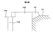
次に図4に基づいて、第二の実施例を説明する。 Next, a second embodiment will be described with reference to FIG.
図4−図6に示す実施例では、貫通孔150−153の溝150B−153Bの上端の周囲にくぼみ150D−153Dを設けてアンカー102の端面における内周部と外周部との連通路をより大きくした。
In the embodiment shown in FIG. 4 to FIG. 6, a
さらに、くぼみ150D−153Dの相互の間にV溝180−183を設けた。これにより、接触面160A,B−163A,Bを効果的に減らせるのでさらにスクイーズ効果を低減できた。
Furthermore, V-grooves 180-183 were provided between the
このV溝180−183は外周側より内周側のほうが幅が広くなっており、また、内周側に傾斜190を有している。これにより、燃料の半径方向への移動がよりスムースに行える効果がある。 The V-grooves 180-183 are wider on the inner peripheral side than on the outer peripheral side, and have a slope 190 on the inner peripheral side. Thereby, there exists an effect which can move to the radial direction of a fuel more smoothly.
以上2つの実施例の実施の態様を整理すると以下の通りである。
1.(A)円筒状のアンカー部(102)、アンカー部(102)の中心部に位置するプランジャ部(114A),プランジャ部(114A)の先端に設けられた弁体(114B)とを含んで構成される可動子(114)を有する。
(B)中心部に燃料を導く燃料導入孔(107D)を有する固定コア(107)を有する。
(C)アンカー(102)の端面(122)と固定コア(107)の端面との間に設けられた磁気ギャップ(136)を含む磁気通路(140)に磁束を供給する電磁コイル(105)を備える。
(D)磁気ギャップ(136)を通る磁束によってアンカー(102)の端面(122)と固定コア(107)の端面との間に生起された磁気吸引力でアンカー(102)を固定コア(107)側に引き付けて可動子(114)を駆動し、もって、弁体(114B)を弁座(39)から引き離して弁座(39)に設けた燃料通路(116A)を開く。
(E)アンカー(102)には、
(a)その中央部で固定コア(107)の燃料導入孔(107D)の端部に対面する位置に形成された凹所(123)が形成されている。
(b)その端面に周方向に飛び飛びに形成され、固定コア(107)の端面に接触する凸部区域(160−163)を有する。
(c)その端面に凸部区域(160−163)の残余の部分に形成された凹部区域(122)を有する。
(d)凹部区域(122)に一端が開口し、他端がアンカー(102)の反固定コア側端面(112A)でプランジャ(114A)の周囲に開口する複数の貫通孔(150−153)を有する。
The modes of implementation of the above two embodiments are summarized as follows.
1. (A) A cylindrical anchor portion (102), a plunger portion (114A) located at the center of the anchor portion (102), and a valve body (114B) provided at the tip of the plunger portion (114A). The movable element (114) is provided.
(B) It has the fixed core (107) which has the fuel introduction hole (107D) which guide | induces a fuel to center part.
(C) An electromagnetic coil (105) for supplying magnetic flux to a magnetic path (140) including a magnetic gap (136) provided between the end face (122) of the anchor (102) and the end face of the fixed core (107). Prepare.
(D) The anchor (102) is fixed to the fixed core (107) by the magnetic attractive force generated between the end surface (122) of the anchor (102) and the end surface of the fixed core (107) by the magnetic flux passing through the magnetic gap (136). At the same time, the movable element (114) is driven to pull the valve body (114B) away from the valve seat (39) to open the fuel passage (116A) provided in the valve seat (39).
(E) The anchor (102)
(A) A recess (123) formed at a position facing the end of the fuel introduction hole (107D) of the fixed core (107) is formed at the center.
(B) It has the convex part area | region (160-163) which is formed in the end surface so that it may jump in the circumferential direction and contacts the end surface of the fixed core (107).
(C) It has the recessed area (122) formed in the remaining part of the convex area (160-163) in the end surface.
(D) A plurality of through-holes (150-153) having one end opened in the recess area (122) and the other end opened around the plunger (114A) at the end surface (112A) on the side opposite to the fixed core of the anchor (102). Have.
好適には、
2.アンカー(102)の端面(122)の凸部区域(160−163)が固定コア(107)に接触した状態で、少なくとも貫通孔(150−153)部分において、凹所(123)とアンカー(102)の凸部区域(160−163)より外周側の凹部区域(122)とが連通する。
Preferably,
2. In a state where the convex section (160-163) of the end face (122) of the anchor (102) is in contact with the fixed core (107), at least in the through hole (150-153) portion, the recess (123) and the anchor (102 ) Communicated with the concave section (122) on the outer peripheral side from the convex section (160-163).
好適には、
3.隣接する貫通孔(150−153)の開口と開口との間に凹所(123)側から半径方向外側に向かって放射状に延びる溝(180−183)が形成されており、
かくして、アンカー(102)の端面(122)には貫通孔(150−153)の開口と凸部区域(160−163)と溝(180−183)と次の貫通孔(150−153)の開口が交互に特定の間隔を置いて形成されている。
Preferably,
3. Grooves (180-183) extending radially outward from the recess (123) side are formed between the openings of the adjacent through holes (150-153),
Thus, the end face (122) of the anchor (102) has an opening of the through hole (150-153), a convex section (160-163), a groove (180-183), and an opening of the next through hole (150-153). Are alternately formed at specific intervals.
好適には、
4.溝(180−183)はV溝である。
Preferably,
4). The groove (180-183) is a V-groove.
好適には、
5.V溝(180−183)は凹所(123)側に傾斜している。
Preferably,
5. The V-groove (180-183) is inclined toward the recess (123).
具体的には、
6.金属材製のパイプ(101)の内側に固定コア(107)を固定し、アンカー(102)が固定コア(107)に対して磁気吸引ギャップ(136)を隔てて対面するように配置して、可動子(114)を弁座(39)と固定コア(107)との間で往復動可能に金属パイプ(101)内に配置し、パイプ(101)の外側に環状コイル(105)とこの環状コイル(105)の上下,周囲を取り巻くヨーク(103,106)を装着して成り、アンカー(102)は、軸方向に延びる複数個の燃料通路用貫通孔(150−153)を有し、貫通孔(150−153)は周方向に特定の間隔を保って配置されており、当該貫通孔(150−153)同士の間に固定コア(107)と接触する端面が飛び飛び、すなわち不連続に形成されるように構成した。
In particular,
6). The fixed core (107) is fixed inside the pipe (101) made of a metal material, and the anchor (102) is arranged so as to face the fixed core (107) with a magnetic attraction gap (136) therebetween, A mover (114) is disposed in the metal pipe (101) so as to be able to reciprocate between the valve seat (39) and the fixed core (107), and an annular coil (105) and the annular coil are formed outside the pipe (101). The yoke (103, 106) surrounding the upper and lower sides and the periphery of the coil (105) is mounted, and the anchor (102) has a plurality of fuel passage through holes (150-153) extending in the axial direction. The holes (150-153) are arranged at a specific interval in the circumferential direction, and the end surface that contacts the fixed core (107) jumps between the through holes (150-153), that is, is formed discontinuously. To be Configuration was.
なお、図1の符号111は、磁気通路140を形成するパイプ部材に設けた環状溝で、磁気絞りを形成する。この磁気絞りは、磁気ギャップ136に対面する位置に形成されている。
以上の実施例では以下の特徴である構成によって、従来技術では得られない効果を得ることができた。 In the above-described embodiments, effects that cannot be obtained by the prior art can be obtained by the configuration having the following features.
a.衝突部の凸部区域(つまり接触面160−163)が不連続となる部分で、接触面はアンカーに設けた貫通孔に隣接している。つまり、隣接する凸部区域(接触面)の間に貫通孔の上端が開口する。より好適には隣接する凸部区域(接触面)の間に凹部区域が形成されており、その凹部区域に貫通孔の上端が開口する。 a. The contact area is adjacent to a through-hole provided in the anchor at a portion where the convex area of the collision part (that is, the contact surface 160-163) is discontinuous. That is, the upper end of the through hole opens between adjacent convex section areas (contact surfaces). More preferably, a recessed area is formed between adjacent raised areas (contact surfaces), and the upper end of the through hole opens in the recessed area.
b.凸部区域(接触面)が不連続となる部分に隣接する貫通孔は、側方と連通している。つまり、貫通孔よりアンカーの内側方向においては凹所123に連通し、アンカーの外側方向においてはアンカー上端面に設けた凹部区域によってアンカー側周部の燃料通路まで連通している。
b. The through hole adjacent to the portion where the convex region (contact surface) is discontinuous communicates with the side. That is, it communicates with the
c.凸部区域(接触面)が不連続となる部分に隣接する貫通孔は、主たる燃料通路を形成する。つまり、燃料のほとんどが貫通孔を通して燃料通路118に供給される。また、燃料通路118から凹所123に逆流する。このとき、貫通孔は固定コアの燃料導入項と凹所との間に隙間に対面する位置に開口しているので、燃料の流れはプランジャの軸線に沿った真直ぐな流れになり、流体抵抗が少ないので、アンカーの動きがスムースになる。その結果、可動子114の応答性が上がり、開閉弁の応答性が改善される。
c. The through hole adjacent to the portion where the convex region (contact surface) becomes discontinuous forms a main fuel passage. That is, most of the fuel is supplied to the
その他の効果は以下の通りである。 Other effects are as follows.
a.の効果は凸部区域(接触面)が不連続となっていることで、凸部区域(接触面)の内外への燃料の移動が容易に行われる。不連続となる部分がアンカーの貫通孔に隣接していることで、閉弁時にアンカー下流側の面が押出した燃料が容易にアンカー上流側に流れ、なおかつ凸部区域(接触面)の内外及び凸部区域(接触面)へ供給されるため、弁体を貼り付けるように作用するスクイーズ効果による力が減少する。 a. The effect of is that the convex area (contact surface) is discontinuous, so that the fuel can easily move in and out of the convex area (contact surface). Because the discontinuous part is adjacent to the through hole of the anchor, the fuel extruded from the surface on the downstream side of the anchor easily flows to the upstream side of the anchor when the valve is closed. Since it is supplied to the convex area (contact surface), the force due to the squeeze effect that acts to stick the valve element is reduced.
つまり、単純に孔が空いているアンカーや、単純に凸部区域(接触面)が付いているアンカーでは効果が小さい。凸部区域(接触面)の外側や内側だけに孔が空いていても凸部区域(接触面)内外の燃料の移動が妨げられ、貼り付き易い。 That is, the effect is small in an anchor having a simple hole or an anchor having a convex area (contact surface). Even if there is a hole only outside or inside the convex area (contact surface), the movement of the fuel inside and outside the convex area (contact surface) is hindered and easily sticks.
b.凸部区域(接触面)が不連続となる部分に隣接する貫通孔が、側方(アンカーに設けた凹所の側)と連通していることにより、燃料の供給および移動がより容易になる。アンカーの貫通孔がコアに面している場合、最小の断面積はコアとアンカーの隙間部に形成されるため、単純に孔を設けても絞りが大きくて効果が低い。このため、燃料が入ってくる経路はコア内側,アンカー外側,貫通孔となるはずが、貫通孔の効果が小さくなってしまう。そこで、貫通孔が側方(アンカーに設けた凹所の側)と連通するようにすることで、燃料の流れが容易になり、貫通孔からの燃料供給が容易になる。この結果、隙間部にも供給され易くなり、結果としてスクイーズ効果による貼り付きを低減できる。 b. The through-hole adjacent to the portion where the convex section (contact surface) is discontinuous communicates with the side (the side of the recess provided in the anchor), thereby facilitating fuel supply and movement. . When the through hole of the anchor faces the core, the minimum cross-sectional area is formed in the gap portion between the core and the anchor. Therefore, even if the hole is simply provided, the aperture is large and the effect is low. For this reason, the route through which the fuel enters should be the inside of the core, the outside of the anchor, and the through hole, but the effect of the through hole is reduced. Therefore, by allowing the through hole to communicate with the side (the side of the recess provided in the anchor), the flow of fuel is facilitated, and fuel supply from the through hole is facilitated. As a result, it can be easily supplied to the gap, and as a result, sticking due to the squeeze effect can be reduced.
c.主たる燃料通路は、アンカーに設けられた燃料通路の中で最も大きい断面積を有する。このため、主たる燃料通路を形成している貫通孔に衝突部(接触面)が隣接していることで、流体抵抗の低減効果を最も大きくできる。また、主たる燃料通路と、貼り付き防止のための燃料通路を兼ねることができるため、磁気吸引面積を小さくせずにすむ。 c. The main fuel passage has the largest cross-sectional area among the fuel passages provided in the anchor. For this reason, the impact resistance (contact surface) is adjacent to the through-hole forming the main fuel passage, so that the effect of reducing the fluid resistance can be maximized. Further, since the main fuel passage can serve as the fuel passage for preventing sticking, it is not necessary to reduce the magnetic attraction area.
本発明は燃料をシリンダ内に直接噴射するいわゆる筒内噴射式内燃機関の燃料噴射弁に用いて好適である。また、これを吸気管に取り付けて、吸気弁上流からシリンダ内に燃料を供給するいわゆるポート噴射式内燃機関の燃料噴射弁に用いることもできる。 The present invention is suitable for use in a fuel injection valve of a so-called in-cylinder internal combustion engine in which fuel is directly injected into a cylinder. It can also be used as a fuel injection valve of a so-called port injection type internal combustion engine that is attached to an intake pipe and supplies fuel into the cylinder from the upstream side of the intake valve.
123 凹所123 recess
107 固定コア107 Fixed core
107D 燃料導入孔107D Fuel introduction hole
114A プランジャ114A Plunger
150−153 貫通孔150-153 through hole
102 アンカー102 anchor
150B−153B 溝150B-153B groove
122 凹部区域122 recessed area
180−183 V溝180-183 V groove
Claims (4)
中心部に燃料を導く燃料導入孔を有する固定コアと、
前記アンカーの端面と前記固定コアの端面との間に設けられた磁気ギャップを含む磁気通路に磁束を供給する電磁コイルとを備え、
前記磁気ギャップを通る磁束によって前記アンカーの端面と前記固定コアの端面との間に生起された磁気吸引力で前記アンカーを前記固定コア側に引き付けて前記可動子を駆動し、
もって、前記弁体を弁座から引き離して当該弁座に設けた燃料通路を開く燃料噴射弁において、
前記アンカーは、
その中央部で前記固定コアの前記燃料導入孔の端部に対面する位置に形成された凹所と、
その端面に周方向に飛び飛びに形成され、前記固定コアの端面に接触する凸部区域と、
その端面に前記凸部区域の残余の部分に形成された凹部区域と、
当該凹部区域と前記凹所の底面とに跨って一端が開口し、他端が前記アンカーの反固定コア側端面で前記プランジャの周囲に開口する複数の貫通孔を有し、
前記凹部区域に開口する前記貫通孔の開口部分は、周方向に飛び飛びに形成された前記凸部区域の間に設けられ、
前記アンカーの端面の前記凸部区域が前記固定コアに接触した状態で、少なくとも前記貫通孔部分において、前記凹所と前記アンカーの前記凸部区域より外周側の凹部区域とが連通する
ことを特徴とする電磁燃料噴射弁。A mover configured to include a cylindrical anchor part, a plunger part located at the center part of the anchor part, and a valve body provided at the tip of the plunger part ,
A fixed core having a fuel introduction hole for guiding the fuel to the center;
An electromagnetic coil for supplying magnetic flux to a magnetic path including a magnetic gap provided between an end face of the anchor and an end face of the fixed core;
The anchor is attracted to the fixed core side by a magnetic attraction generated between the end face of the anchor and the end face of the fixed core by the magnetic flux passing through the magnetic gap, and the movable element is driven.
Therefore, in the fuel injection valve that opens the fuel passage provided in the valve seat by separating the valve body from the valve seat,
Said anchor over is,
A recess formed at a position facing the end of the fuel introduction hole of the fixed core at the center thereof;
A projecting section that is formed on the end face so as to jump in the circumferential direction and contacts the end face of the fixed core;
A recessed area formed on the end face of the remaining area of the raised area;
One end opening across the bottom surface of the recess zone and the recess, have a plurality of through holes opening on the periphery of the plunger and the other end in the unfixed core side end face of the anchor,
The opening portion of the through hole that opens to the concave section is provided between the convex sections formed so as to jump in the circumferential direction,
In a state where the convex section of the end face of the anchor is in contact with the fixed core, at least in the through-hole portion, the concave section communicates with the concave section on the outer peripheral side from the convex section of the anchor. > An electromagnetic fuel injection valve characterized by that.
隣接する貫通孔の開口と開口との間に前記凹所側から半径方向外側に向かって放射状に延びる溝が形成されており、
かくして、前記アンカーの端面に、前記貫通孔の開口と前記凸部区域と前記溝と次の貫通孔の開口とを特定の間隔を置いて形成した
ことを特徴とする燃料噴射弁。The electromagnetic fuel injection valve according to claim 1,
It is formed with a groove extending radially radially outward from the recess side between the opening and the opening of the next adjacent through-holes,
Thus, the end face of the anchor, said through an opening and the protrusion section of the hole the groove and the next through-hole fuel injection valve and opening and wherein <br/> to the formation at a specific interval .
前記溝はV溝であることを特徴とする燃料噴射弁。The electromagnetic fuel injection valve according to claim 2 ,
The fuel injection valve, wherein the groove is a V-groove.
前記V溝は前記凹所側に傾斜していることを特徴とする燃料噴射弁。The electromagnetic fuel injection valve according to claim 3 ,
The fuel injection valve, wherein the V-groove is inclined toward the recess.
Applications Claiming Priority (1)
| Application Number | Priority Date | Filing Date | Title |
|---|---|---|---|
| PCT/JP2006/319621 WO2008038395A1 (en) | 2006-09-25 | 2006-09-25 | Fuel injection valve |
Publications (2)
| Publication Number | Publication Date |
|---|---|
| JPWO2008038395A1 JPWO2008038395A1 (en) | 2010-01-28 |
| JP4887369B2 true JP4887369B2 (en) | 2012-02-29 |
Family
ID=39229843
Family Applications (1)
| Application Number | Title | Priority Date | Filing Date |
|---|---|---|---|
| JP2008536272A Active JP4887369B2 (en) | 2006-09-25 | 2006-09-25 | Fuel injection valve |
Country Status (5)
| Country | Link |
|---|---|
| US (1) | US8104698B2 (en) |
| EP (1) | EP2077389B1 (en) |
| JP (1) | JP4887369B2 (en) |
| CN (1) | CN101506511B (en) |
| WO (1) | WO2008038395A1 (en) |
Families Citing this family (23)
| Publication number | Priority date | Publication date | Assignee | Title |
|---|---|---|---|---|
| DE102008040015A1 (en) * | 2008-06-30 | 2009-12-31 | Robert Bosch Gmbh | Solenoid valve, fuel injector and manufacturing process |
| JP5048617B2 (en) * | 2008-09-17 | 2012-10-17 | 日立オートモティブシステムズ株式会社 | Fuel injection valve for internal combustion engine |
| JP5222253B2 (en) * | 2009-08-31 | 2013-06-26 | 日立オートモティブシステムズ株式会社 | Fuel injection valve |
| JP5178683B2 (en) * | 2009-10-21 | 2013-04-10 | 日立オートモティブシステムズ株式会社 | Electromagnetic fuel injection valve |
| US8215573B2 (en) * | 2010-05-14 | 2012-07-10 | Continental Automotive Systems Us, Inc. | Automotive gasoline solenoid double pole direct injector |
| EP2436910B1 (en) * | 2010-10-01 | 2017-05-03 | Continental Automotive GmbH | Valve assembly for an injection valve and injection valve |
| US8729995B2 (en) | 2010-12-20 | 2014-05-20 | Caterpillar Inc. | Solenoid actuator and fuel injector using same |
| JP5537472B2 (en) * | 2011-03-10 | 2014-07-02 | 日立オートモティブシステムズ株式会社 | Fuel injection device |
| JP2013072298A (en) * | 2011-09-27 | 2013-04-22 | Hitachi Automotive Systems Ltd | Fuel injection valve |
| DE102011084704A1 (en) | 2011-10-18 | 2013-04-18 | Robert Bosch Gmbh | Alignment element for an injection valve and method for producing an injection valve |
| JP5965253B2 (en) * | 2012-02-20 | 2016-08-03 | 株式会社デンソー | Fuel injection valve |
| JP6015870B2 (en) * | 2012-02-20 | 2016-10-26 | 株式会社デンソー | Fuel injection valve |
| JP5644819B2 (en) * | 2012-08-08 | 2014-12-24 | 株式会社デンソー | Fuel injection valve |
| JP5994642B2 (en) * | 2013-01-07 | 2016-09-21 | マツダ株式会社 | Direct injection engine fuel injection system |
| JP6087210B2 (en) | 2013-05-24 | 2017-03-01 | 日立オートモティブシステムズ株式会社 | Fuel injection valve |
| WO2016042753A1 (en) * | 2014-09-17 | 2016-03-24 | 株式会社デンソー | Fuel injection valve |
| DE102014221586A1 (en) * | 2014-10-23 | 2016-04-28 | Robert Bosch Gmbh | fuel injector |
| EP3076004B1 (en) * | 2015-04-02 | 2018-09-12 | Continental Automotive GmbH | Valve assembly with a particle retainer element and fluid injection valve |
| JP6571410B2 (en) * | 2015-06-29 | 2019-09-04 | 日立オートモティブシステムズ株式会社 | solenoid valve |
| JP6483574B2 (en) | 2015-08-25 | 2019-03-13 | 株式会社デンソー | Fuel injection device |
| JP6692446B2 (en) * | 2016-11-07 | 2020-05-13 | 三菱電機株式会社 | Fuel injection valve |
| JP6481708B2 (en) * | 2017-04-25 | 2019-03-13 | 株式会社デンソー | Fuel injection valve |
| JP6788085B1 (en) * | 2019-09-20 | 2020-11-18 | 株式会社ケーヒン | Electromagnetic fuel injection valve |
Family Cites Families (17)
| Publication number | Priority date | Publication date | Assignee | Title |
|---|---|---|---|---|
| JPS58178863A (en) | 1982-04-14 | 1983-10-19 | Nippon Denso Co Ltd | Electromagnetic fuel injection valve |
| DE4415850A1 (en) * | 1994-05-05 | 1995-11-09 | Bosch Gmbh Robert | Valve needle for an electromagnetically actuated valve |
| DE19816315A1 (en) * | 1998-04-11 | 1999-10-14 | Bosch Gmbh Robert | Fuel injector |
| JP2000055229A (en) * | 1998-08-07 | 2000-02-22 | Mitsubishi Electric Corp | Fluid controlling solenoid valve |
| DE10039083A1 (en) * | 2000-08-10 | 2002-02-21 | Bosch Gmbh Robert | Fuel injector |
| JP2002295329A (en) * | 2001-01-25 | 2002-10-09 | Hitachi Ltd | Electromagnetic fuel injection valve and fuel injection device |
| ITTO20010969A1 (en) * | 2001-10-12 | 2003-04-12 | C R F Societa Con Sortile Per | IMPROVEMENTS TO A FUEL INJECTOR FOR ENDOTHERMAL ENGINES, WITH AN ELECTROMAGNETIC DOSING VALVE. |
| JP3884310B2 (en) * | 2002-03-22 | 2007-02-21 | 愛三工業株式会社 | Electromagnetic fuel injection valve |
| JP2004270490A (en) * | 2003-03-06 | 2004-09-30 | Denso Corp | Electromagnetic driving device, fuel injection valve using the same, and method for manufacturing the device |
| JP3923935B2 (en) * | 2003-11-05 | 2007-06-06 | 三菱電機株式会社 | Fuel injection valve |
| JP4135628B2 (en) * | 2003-12-04 | 2008-08-20 | トヨタ自動車株式会社 | Fuel injection valve |
| JP4168448B2 (en) | 2004-07-08 | 2008-10-22 | 株式会社デンソー | Fuel injection valve |
| JP2006022727A (en) * | 2004-07-08 | 2006-01-26 | Aisan Ind Co Ltd | Fuel injection valve |
| JP4790441B2 (en) * | 2006-02-17 | 2011-10-12 | 日立オートモティブシステムズ株式会社 | Electromagnetic fuel injection valve and method of assembling the same |
| JP4576345B2 (en) * | 2006-02-17 | 2010-11-04 | 日立オートモティブシステムズ株式会社 | Electromagnetic fuel injection valve |
| JP4211814B2 (en) * | 2006-07-13 | 2009-01-21 | 株式会社日立製作所 | Electromagnetic fuel injection valve |
| WO2008038396A1 (en) * | 2006-09-25 | 2008-04-03 | Hitachi, Ltd. | Fuel injection valve |
-
2006
- 2006-09-25 CN CN2006800556463A patent/CN101506511B/en active Active
- 2006-09-25 JP JP2008536272A patent/JP4887369B2/en active Active
- 2006-09-25 EP EP06810976A patent/EP2077389B1/en active Active
- 2006-09-25 US US12/439,102 patent/US8104698B2/en active Active
- 2006-09-25 WO PCT/JP2006/319621 patent/WO2008038395A1/en active Application Filing
Also Published As
| Publication number | Publication date |
|---|---|
| US20100012754A1 (en) | 2010-01-21 |
| EP2077389B1 (en) | 2013-01-30 |
| US8104698B2 (en) | 2012-01-31 |
| EP2077389A1 (en) | 2009-07-08 |
| CN101506511B (en) | 2011-10-26 |
| WO2008038395A1 (en) | 2008-04-03 |
| JPWO2008038395A1 (en) | 2010-01-28 |
| CN101506511A (en) | 2009-08-12 |
| EP2077389A4 (en) | 2011-10-12 |
Similar Documents
| Publication | Publication Date | Title |
|---|---|---|
| JP4887369B2 (en) | Fuel injection valve | |
| JP4988750B2 (en) | Fuel injection valve | |
| JP6087210B2 (en) | Fuel injection valve | |
| JP2013072298A (en) | Fuel injection valve | |
| JP4211814B2 (en) | Electromagnetic fuel injection valve | |
| JP2010084552A (en) | Solenoid type fuel injection valve | |
| JP5537472B2 (en) | Fuel injection device | |
| JP5488120B2 (en) | Fuel injection valve | |
| JP2010180758A (en) | Fuel injection valve | |
| JP2011094632A (en) | Solenoid fuel injection valve and method for assembling the same | |
| JP2010281248A (en) | Solenoid fuel injection valve | |
| JP3633885B2 (en) | Electromagnetic valve device and fuel injection device using the same | |
| JP2013151915A (en) | Fuel injection valve | |
| JP2011117362A (en) | Electromagnetic fuel injection valve | |
| JPWO2019003719A1 (en) | High pressure fuel supply pump | |
| JP2017137873A (en) | Fuel injection device | |
| JP6453381B2 (en) | Fuel injection device | |
| JP6595701B2 (en) | Fuel injection device | |
| JP2015121188A (en) | Fuel injection valve | |
| JP6151336B2 (en) | Fuel injection device | |
| JP6063894B2 (en) | Fuel injection device | |
| JP7171448B2 (en) | fuel injector | |
| WO2019163383A1 (en) | Fuel injection valve and method for assembling same | |
| JP2019039437A (en) | Fuel injection device |
Legal Events
| Date | Code | Title | Description |
|---|---|---|---|
| A711 | Notification of change in applicant |
Free format text: JAPANESE INTERMEDIATE CODE: A712 Effective date: 20100107 |
|
| A131 | Notification of reasons for refusal |
Free format text: JAPANESE INTERMEDIATE CODE: A131 Effective date: 20110208 |
|
| A521 | Request for written amendment filed |
Free format text: JAPANESE INTERMEDIATE CODE: A523 Effective date: 20110830 |
|
| TRDD | Decision of grant or rejection written | ||
| A01 | Written decision to grant a patent or to grant a registration (utility model) |
Free format text: JAPANESE INTERMEDIATE CODE: A01 Effective date: 20111115 |
|
| A01 | Written decision to grant a patent or to grant a registration (utility model) |
Free format text: JAPANESE INTERMEDIATE CODE: A01 |
|
| A61 | First payment of annual fees (during grant procedure) |
Free format text: JAPANESE INTERMEDIATE CODE: A61 Effective date: 20111212 |
|
| FPAY | Renewal fee payment (event date is renewal date of database) |
Free format text: PAYMENT UNTIL: 20141216 Year of fee payment: 3 |
|
| R150 | Certificate of patent or registration of utility model |
Ref document number: 4887369 Country of ref document: JP Free format text: JAPANESE INTERMEDIATE CODE: R150 Free format text: JAPANESE INTERMEDIATE CODE: R150 |
|
| S533 | Written request for registration of change of name |
Free format text: JAPANESE INTERMEDIATE CODE: R313533 |
|
| R350 | Written notification of registration of transfer |
Free format text: JAPANESE INTERMEDIATE CODE: R350 |
|
| R250 | Receipt of annual fees |
Free format text: JAPANESE INTERMEDIATE CODE: R250 |