EP3075999A1 - Internal combustion engine - Google Patents
Internal combustion engine Download PDFInfo
- Publication number
- EP3075999A1 EP3075999A1 EP16162152.9A EP16162152A EP3075999A1 EP 3075999 A1 EP3075999 A1 EP 3075999A1 EP 16162152 A EP16162152 A EP 16162152A EP 3075999 A1 EP3075999 A1 EP 3075999A1
- Authority
- EP
- European Patent Office
- Prior art keywords
- cylinder
- exhaust
- passage
- exhaust gas
- fuel
- Prior art date
- Legal status (The legal status is an assumption and is not a legal conclusion. Google has not performed a legal analysis and makes no representation as to the accuracy of the status listed.)
- Withdrawn
Links
Images




Classifications
-
- F—MECHANICAL ENGINEERING; LIGHTING; HEATING; WEAPONS; BLASTING
- F02—COMBUSTION ENGINES; HOT-GAS OR COMBUSTION-PRODUCT ENGINE PLANTS
- F02M—SUPPLYING COMBUSTION ENGINES IN GENERAL WITH COMBUSTIBLE MIXTURES OR CONSTITUENTS THEREOF
- F02M26/00—Engine-pertinent apparatus for adding exhaust gases to combustion-air, main fuel or fuel-air mixture, e.g. by exhaust gas recirculation [EGR] systems
- F02M26/13—Arrangement or layout of EGR passages, e.g. in relation to specific engine parts or for incorporation of accessories
- F02M26/14—Arrangement or layout of EGR passages, e.g. in relation to specific engine parts or for incorporation of accessories in relation to the exhaust system
-
- F—MECHANICAL ENGINEERING; LIGHTING; HEATING; WEAPONS; BLASTING
- F01—MACHINES OR ENGINES IN GENERAL; ENGINE PLANTS IN GENERAL; STEAM ENGINES
- F01N—GAS-FLOW SILENCERS OR EXHAUST APPARATUS FOR MACHINES OR ENGINES IN GENERAL; GAS-FLOW SILENCERS OR EXHAUST APPARATUS FOR INTERNAL-COMBUSTION ENGINES
- F01N13/00—Exhaust or silencing apparatus characterised by constructional features
- F01N13/011—Exhaust or silencing apparatus characterised by constructional features having two or more purifying devices arranged in parallel
-
- F—MECHANICAL ENGINEERING; LIGHTING; HEATING; WEAPONS; BLASTING
- F01—MACHINES OR ENGINES IN GENERAL; ENGINE PLANTS IN GENERAL; STEAM ENGINES
- F01N—GAS-FLOW SILENCERS OR EXHAUST APPARATUS FOR MACHINES OR ENGINES IN GENERAL; GAS-FLOW SILENCERS OR EXHAUST APPARATUS FOR INTERNAL-COMBUSTION ENGINES
- F01N13/00—Exhaust or silencing apparatus characterised by constructional features
- F01N13/08—Other arrangements or adaptations of exhaust conduits
- F01N13/10—Other arrangements or adaptations of exhaust conduits of exhaust manifolds
- F01N13/107—More than one exhaust manifold or exhaust collector
-
- F—MECHANICAL ENGINEERING; LIGHTING; HEATING; WEAPONS; BLASTING
- F01—MACHINES OR ENGINES IN GENERAL; ENGINE PLANTS IN GENERAL; STEAM ENGINES
- F01N—GAS-FLOW SILENCERS OR EXHAUST APPARATUS FOR MACHINES OR ENGINES IN GENERAL; GAS-FLOW SILENCERS OR EXHAUST APPARATUS FOR INTERNAL-COMBUSTION ENGINES
- F01N3/00—Exhaust or silencing apparatus having means for purifying, rendering innocuous, or otherwise treating exhaust
- F01N3/02—Exhaust or silencing apparatus having means for purifying, rendering innocuous, or otherwise treating exhaust for cooling, or for removing solid constituents of, exhaust
- F01N3/021—Exhaust or silencing apparatus having means for purifying, rendering innocuous, or otherwise treating exhaust for cooling, or for removing solid constituents of, exhaust by means of filters
-
- F—MECHANICAL ENGINEERING; LIGHTING; HEATING; WEAPONS; BLASTING
- F01—MACHINES OR ENGINES IN GENERAL; ENGINE PLANTS IN GENERAL; STEAM ENGINES
- F01N—GAS-FLOW SILENCERS OR EXHAUST APPARATUS FOR MACHINES OR ENGINES IN GENERAL; GAS-FLOW SILENCERS OR EXHAUST APPARATUS FOR INTERNAL-COMBUSTION ENGINES
- F01N3/00—Exhaust or silencing apparatus having means for purifying, rendering innocuous, or otherwise treating exhaust
- F01N3/08—Exhaust or silencing apparatus having means for purifying, rendering innocuous, or otherwise treating exhaust for rendering innocuous
- F01N3/10—Exhaust or silencing apparatus having means for purifying, rendering innocuous, or otherwise treating exhaust for rendering innocuous by thermal or catalytic conversion of noxious components of exhaust
- F01N3/24—Exhaust or silencing apparatus having means for purifying, rendering innocuous, or otherwise treating exhaust for rendering innocuous by thermal or catalytic conversion of noxious components of exhaust characterised by constructional aspects of converting apparatus
- F01N3/36—Arrangements for supply of additional fuel
-
- F—MECHANICAL ENGINEERING; LIGHTING; HEATING; WEAPONS; BLASTING
- F02—COMBUSTION ENGINES; HOT-GAS OR COMBUSTION-PRODUCT ENGINE PLANTS
- F02M—SUPPLYING COMBUSTION ENGINES IN GENERAL WITH COMBUSTIBLE MIXTURES OR CONSTITUENTS THEREOF
- F02M26/00—Engine-pertinent apparatus for adding exhaust gases to combustion-air, main fuel or fuel-air mixture, e.g. by exhaust gas recirculation [EGR] systems
- F02M26/50—Arrangements or methods for preventing or reducing deposits, corrosion or wear caused by impurities
-
- F—MECHANICAL ENGINEERING; LIGHTING; HEATING; WEAPONS; BLASTING
- F01—MACHINES OR ENGINES IN GENERAL; ENGINE PLANTS IN GENERAL; STEAM ENGINES
- F01N—GAS-FLOW SILENCERS OR EXHAUST APPARATUS FOR MACHINES OR ENGINES IN GENERAL; GAS-FLOW SILENCERS OR EXHAUST APPARATUS FOR INTERNAL-COMBUSTION ENGINES
- F01N2610/00—Adding substances to exhaust gases
- F01N2610/03—Adding substances to exhaust gases the substance being hydrocarbons, e.g. engine fuel
-
- F—MECHANICAL ENGINEERING; LIGHTING; HEATING; WEAPONS; BLASTING
- F02—COMBUSTION ENGINES; HOT-GAS OR COMBUSTION-PRODUCT ENGINE PLANTS
- F02B—INTERNAL-COMBUSTION PISTON ENGINES; COMBUSTION ENGINES IN GENERAL
- F02B75/00—Other engines
- F02B75/16—Engines characterised by number of cylinders, e.g. single-cylinder engines
- F02B75/18—Multi-cylinder engines
- F02B2075/1804—Number of cylinders
- F02B2075/1812—Number of cylinders three
-
- F—MECHANICAL ENGINEERING; LIGHTING; HEATING; WEAPONS; BLASTING
- F02—COMBUSTION ENGINES; HOT-GAS OR COMBUSTION-PRODUCT ENGINE PLANTS
- F02M—SUPPLYING COMBUSTION ENGINES IN GENERAL WITH COMBUSTIBLE MIXTURES OR CONSTITUENTS THEREOF
- F02M26/00—Engine-pertinent apparatus for adding exhaust gases to combustion-air, main fuel or fuel-air mixture, e.g. by exhaust gas recirculation [EGR] systems
- F02M26/02—EGR systems specially adapted for supercharged engines
- F02M26/04—EGR systems specially adapted for supercharged engines with a single turbocharger
- F02M26/05—High pressure loops, i.e. wherein recirculated exhaust gas is taken out from the exhaust system upstream of the turbine and reintroduced into the intake system downstream of the compressor
-
- Y—GENERAL TAGGING OF NEW TECHNOLOGICAL DEVELOPMENTS; GENERAL TAGGING OF CROSS-SECTIONAL TECHNOLOGIES SPANNING OVER SEVERAL SECTIONS OF THE IPC; TECHNICAL SUBJECTS COVERED BY FORMER USPC CROSS-REFERENCE ART COLLECTIONS [XRACs] AND DIGESTS
- Y02—TECHNOLOGIES OR APPLICATIONS FOR MITIGATION OR ADAPTATION AGAINST CLIMATE CHANGE
- Y02T—CLIMATE CHANGE MITIGATION TECHNOLOGIES RELATED TO TRANSPORTATION
- Y02T10/00—Road transport of goods or passengers
- Y02T10/10—Internal combustion engine [ICE] based vehicles
- Y02T10/12—Improving ICE efficiencies
Definitions
- the present invention relates to an internal combustion engine.
- a diesel engine disclosed in Japanese Unexamined Patent Publication No. 2001-280125 is known as an internal combustion engine in the related art.
- the diesel engine disclosed in Japanese Unexamined Patent Publication No. 2001-280125 includes first to fourth cylinders, and intake air is introduced to combustion chambers of the respective cylinders through an intake manifold and an intake pipe.
- Exhaust gas which is generated in the combustion chambers of the respective cylinders, is discharged to an exhaust manifold from exhaust ports of the respective cylinders.
- An exhaust gas collecting pipe which introduces exhaust gas to a turbine of a turbocharger, is connected to a portion of the exhaust manifold that corresponds to the fourth cylinder. The exhaust gas is discharged to an exhaust pipe from the turbine.
- a fuel addition nozzle which injects fuel to the exhaust gas collecting pipe, is mounted on a cylinder head of the diesel engine so as to face the exhaust port of the fourth cylinder.
- One end of an exhaust gas recirculation pipe (EGR pipe) which allows a part of exhaust gas to return to an intake system, is connected to a portion of the exhaust manifold that corresponds to the first cylinder.
- An EGR cooler and an EGR valve are provided on the EGR pipe.
- An object of the invention is to provide an internal combustion engine that can reduce the amount of added fuel flowing to an exhaust gas recirculation (EGR) system.
- EGR exhaust gas recirculation
- an internal combustion engine including: an engine body that includes a plurality of cylinders arranged in one direction; an intake passage that is connected to the engine body through an intake manifold and allows air to be taken into the cylinders; an exhaust passage which is connected to the engine body through an exhaust manifold and through which exhaust gas generated in the cylinders is discharged; a fuel addition valve that adds fuel to the exhaust gas; and an exhaust gas recirculation system including an exhaust gas recirculation passage that connects the exhaust manifold to an intake system including the intake manifold and the intake passage and allows a part of the exhaust gas to return to the cylinders as exhaust gas recirculation gas.
- the exhaust passage is connected to a portion of the exhaust manifold that corresponds to the cylinder positioned at one end among the plurality of cylinders, the fuel addition valve is disposed at a portion that corresponds to the cylinder positioned at the one end and adds the fuel when gas is exhausted from the cylinder positioned at the one end, the exhaust gas recirculation passage is connected to a portion of the exhaust manifold that corresponds to the cylinder positioned at the other end among the plurality of cylinders, and the cylinder positioned at the other end explodes after the explosion of the cylinder positioned at the one end.
- the cylinder which is adjacent to the cylinder positioned at the other end, may explode after the explosion of the cylinder positioned at the other end.
- the cylinder which is adjacent to the cylinder positioned at the other end among the plurality of cylinders, explodes, most of the exhaust gas generated in the cylinder flows in the exhaust passage through the exhaust manifold.
- the added fuel which remains in the exhaust manifold between the cylinder positioned at one end of the exhaust manifold and the cylinder adjacent to the cylinder positioned at the other end of the exhaust manifold, is pushed back toward the exhaust passage by the exhaust gas. For this reason, the flow of the added fuel in the exhaust gas recirculation passage is further suppressed. Accordingly, it is possible to further reduce the amount of the added fuel flowing to the exhaust gas recirculation (EGR) system.
- EGR exhaust gas recirculation
- the cylinders may explode in turn toward the one side from the other side after the explosion of the cylinder positioned at the other end.
- EGR exhaust gas recirculation
- an internal combustion engine that can reduce the amount of added fuel flowing to the exhaust gas recirculation (EGR) system.
- EGR exhaust gas recirculation
- Fig. 1 is a diagram illustrating the schematic structure of a diesel engine as an internal combustion engine according to a first embodiment.
- a diesel engine (hereinafter, simply referred to as an engine) 1 that is an internal combustion engine according to this embodiment is an in-line three-cylinder diesel engine that is mounted on a vehicle.
- the engine 1 includes an engine body 2.
- the engine body 2 includes three cylinders 3 (a #1 cylinder 3a, a #2 cylinder 3b, and a #3 cylinder 3c) that are arranged in one direction and three injectors 4 that inject fuel into combustion chambers of the cylinders 3, respectively.
- a common rail (not illustrated), which stores fuel, is connected to the respective injectors 4.
- the engine 1 includes a turbocharger 9 for pressurizing air, which is to be taken into the combustion chambers of the respective cylinders 3, by the energy of exhaust gas generated in the combustion chambers of the respective cylinders 3.
- the turbocharger 9 includes a compressor 10 that is provided on the intake passage 5 and a turbine 11 that is provided on the exhaust passage 7.
- An air cleaner 13 is provided on the intake passage 5 on the upstream side of the compressor 10.
- An intercooler 14 and a throttle valve 15 are provided on the intake passage 5 on the downstream side of the compressor 10.
- the intake passage 5, the intake manifold 6, the compressor 10, the air cleaner 13, the intercooler 14, and the throttle valve 15 form an intake system 16.
- a diesel particulate filter (DPF) 17 and a NO x reduction catalyst 18 are provided on the exhaust passage 7 on the downstream side of the turbine 11.
- the exhaust passage 7, the exhaust manifold 8, the turbine 11, the DPF 17, and the NO x reduction catalyst 18 form an exhaust system 19.
- a fuel addition valve 20 which adds fuel to exhaust gas generated in the combustion chambers of the respective cylinders 3, is mounted on the engine body 2.
- Fuel is a reducing agent that is used to purify NO x by the NO x reduction catalyst 18.
- the fuel addition valve 20 is disposed at a portion that corresponds to the #3 cylinder 3c positioned at one end (which is close to the exhaust passage 7) among the respective cylinders 3.
- the fuel addition valve 20 is controlled by a controller (not illustrated) so as to add fuel to the exhaust passage 7 when gas is exhausted from the #3 cylinder 3c after the explosion of the #3 cylinder 3c.
- the engine 1 includes an exhaust gas recirculation system (EGR system) 21 for recirculating a part of exhaust gas, which is generated in the combustion chambers of the respective cylinders 3, in the combustion chambers of the respective cylinders 3 as exhaust gas recirculation gas (EGR gas).
- EGR system exhaust gas recirculation system
- the EGR system 21 includes an exhaust gas recirculation passage (EGR passage) 22 that connects the exhaust manifold 8 to the intake manifold 6 and allows the EGR gas to return to the respective cylinders 3, an EGR cooler 23 that is provided on the EGR passage 22 and cools the EGR gas flowing in the EGR passage 22, and an EGR valve 24 that is provided on the EGR passage 22 on the downstream side of the EGR cooler 23 and adjusts the flow rate of the EGR gas returning to the intake manifold 6 from the exhaust manifold 8.
- EGR passage exhaust gas recirculation passage
- one end of the EGR passage 22 is connected to a portion of the exhaust manifold 8 that corresponds to the #1 cylinder 3a positioned at the other end among the respective cylinders 3. Accordingly, a portion, to which the EGR gas is introduced, of the EGR passage 22 is most away from the fuel addition valve 20.
- the other end of the EGR passage 22 is connected to the upstream portion of the intake manifold 6. Meanwhile, the other end of the EGR passage 22 may be connected to the intake passage 5.
- the explosion order of the respective cylinders 3 is the order of the #1 cylinder 3a, the #2 cylinder 3b, and the #3 cylinder 3c. That is, after the explosion of the #3 cylinder 3c that is positioned at one end (which is close to the exhaust passage 7) among the respective cylinders 3, the #1 cylinder 3a that is positioned at the other end (which is close to the EGR passage 22) among the respective cylinders 3 explodes. After that, the #2 cylinder 3b, which is adjacent to the #1 cylinder 3a positioned at the other end among the respective cylinders 3, explodes.
- Fig. 3 is a graph illustrating the time history of the flow rate of exhaust gas that is discharged from the respective cylinders. Meanwhile, in Fig. 3 , a crank angle becomes 0° when the #1 cylinder 3a reaches a compression top dead center. As known from Fig. 3 , gas is exhausted from the #1 cylinder 3a after gas is exhausted from the #3 cylinder 3c.
- a fuel addition period X is a period in which a crank angle is changed by a predetermined angle (for example, 100°) from the point of time when gas starts to be exhausted from the #3 cylinder 3c.
- Fig. 4 is a diagram simply illustrating an example of an engine of which the layout of an exhaust passage 7, an EGR passage 22, and a fuel addition valve 20 is different from that of the first embodiment, as a comparative example.
- the exhaust passage 7 is connected to a portion corresponding to a #1 cylinder 3a.
- the EGR passage 22 is connected to a portion corresponding to a #3 cylinder 3c.
- the fuel addition valve 20 is connected to a portion corresponding to the #1 cylinder 3a.
- the explosion order of the respective cylinders 3 is the order of the #1 cylinder 3a, the #2 cylinder 3b, and the #3 cylinder 3c.
- the fuel addition valve 20 adds fuel when gas is exhausted from the #1 cylinder 3 a.
- the exhaust passage 7 is connected to a portion of the exhaust manifold 8 that corresponds to the #3 cylinder 3c positioned at one end among the respective cylinders 3.
- the EGR passage 22 is connected to a portion of the exhaust manifold 8 that corresponds to the #1 cylinder 3a positioned at the other end among the respective cylinders 3.
- the fuel addition valve 20 is disposed at a portion that corresponds to the #3 cylinder 3c positioned at one end among the respective cylinders 3, and adds fuel when gas is exhausted from the #3 cylinder 3c.
- the #1 cylinder 3a that is positioned at the other end among the respective cylinders 3 explodes.
- Fig. 5 is a graph illustrating the analysis results of the time history of the concentration of the added fuel that flows in the EGR passage 22.
- a broken line P of Fig. 5 indicates the results of the comparative example illustrated in Fig. 4
- a solid line Q of Fig. 5 indicates the results of this embodiment illustrated in Fig. 2 .
- the crank angles of the broken line P and the solid line Q are offset from each other in Fig. 5 so that the broken line P and the solid line Q are easily compared with each other.
- the concentration of the added fuel flowing in the EGR passage 22 becomes high immediately after the addition of fuel and the concentration of the added fuel flowing in the EGR passage 22 then becomes low.
- the added fuel is pushed toward the EGR passage 22 by the exhaust gas generated in the #2 cylinder 3b in the comparative example, slight added fuel is present in the EGR passage 22 even after that.
- the added fuel is pushed back toward the exhaust passage 7 by the exhaust gas generated in the #1 cylinder 3a in this embodiment, the added fuel is hardly present in the EGR passage 22. Accordingly, the concentration of the added fuel flowing in the EGR passage 22 in this embodiment becomes lower than that in the comparative example.
- Fig. 6 is a diagram illustrating the schematic structure of a diesel engine as an internal combustion engine according to a second embodiment.
- a diesel engine (hereinafter, simply referred to as an engine) 30 that is an internal combustion engine according to this embodiment is a V-type eight-cylinder diesel engine that is mounted on a vehicle.
- the engine 30 includes engine bodies 31A and 31B.
- the engine body 31A includes a right bank 33A that includes four cylinders 32A (a #1 cylinder 32a, a #3 cylinder 32c, a #5 cylinder 32e, and a #7 cylinder 32g) arranged in one direction, and four injectors 34A that inject fuel into combustion chambers of the cylinders 32A, respectively.
- the engine body 31B includes a left bank 33B that includes four cylinders 32B (a #2 cylinder 32b, a #4 cylinder 32d, a #6 cylinder 32f, and a #8 cylinder 32h) arranged in one direction, and four injectors 34B that inject fuel into combustion chambers of the cylinders 32B, respectively.
- Intake passages 35A and 35B which allow air to be taken into the combustion chambers of the respective cylinders 32A and 32B, are connected to one sides (sides facing each other) of the engine bodies 31A and 31B through an intake manifold 6.
- Exhaust passages 37A and 37B through which exhaust gas generated in the combustion chambers of the respective cylinders 32A and 32B is discharged, are connected to the other sides of the engine bodies 31A and 31B through exhaust manifolds 38A and 38B, respectively.
- the exhaust passage 37A is connected to a portion of the exhaust manifold 38A that corresponds to the #1 cylinder 32a positioned at one end among the respective cylinders 32A.
- the exhaust passage 37B is connected to a portion of the exhaust manifold 38B that corresponds to the #8 cylinder 32h positioned at one end among the respective cylinders 32B.
- the engine 30 includes turbochargers 39A and 39B for pressurizing air, which is to be taken into the combustion chambers of the respective cylinders 32A and 32B, by the energy of exhaust gas generated in the combustion chambers of the respective cylinders 32A and 32B.
- the turbochargers 39A and 39B include compressors 40A and 40B that are provided on the intake passages 35A and 35B and turbines 41A and 41B that are provided on the exhaust passages 37A and 37B, respectively.
- the intake passages 35A and 35B are connected to a common intake passage 35.
- An air cleaner 43 is provided on the common intake passage 35.
- Intercoolers 44A and 44B and throttle valves 45A and 45B are provided on the intake passages 35A and 35B on the downstream side of the compressors 40A and 40B, respectively.
- the common intake passage 35, the intake passage 35A, the intake manifold 36, the compressor 40A, the air cleaner 43, the intercooler 44A, and the throttle valve 45A form an intake system 46A.
- the common intake passage 35, the intake passage 35B, the intake manifold 36, the compressor 40B, the air cleaner 43, the intercooler 44B, and the throttle valve 45B form an intake system 46B.
- DPFs 47A and 47B and NO x reduction catalysts 48A and 48B are provided on the exhaust passages 37A and 37B on the downstream side of the turbines 41A and 41B, respectively.
- the exhaust passages 37A and 37B, the exhaust manifolds 38A and 38B, the turbines 41A and 41B, the DPFs 47A and 47B, and the NO x reduction catalysts 48A and 48B form exhaust systems 49A and 49B, respectively.
- Fuel addition valves 50A and 50B which add fuel to exhaust gas generated in the combustion chambers of the respective cylinders 32A and 32B, are mounted on the engine bodies 31A and 31B, respectively. Also as illustrated in Fig. 7 , the fuel addition valve 50A is disposed at a portion that corresponds to the #1 cylinder 32a positioned at one end (which is close to the exhaust passage 37A) among the respective cylinders 32A. The fuel addition valve 50A is controlled by a controller (not illustrated) so as to add fuel to the exhaust passage 37A when gas is exhausted from the #1 cylinder 32a after the explosion of the #1 cylinder 32a.
- the fuel addition valve 50B is disposed at a portion that corresponds to the #8 cylinder 32h positioned at one end (which is close to the exhaust passage 37B) among the respective cylinders 32B.
- the fuel addition valve 50B is controlled by a controller (not illustrated) so as to add fuel to the exhaust passage 37B when gas is exhausted from the #8 cylinder 32h after the explosion of the #8 cylinder 32h.
- the engine 30 includes exhaust gas recirculation systems (EGR systems) 51A and 51B for recirculating a part of exhaust gas, which is generated in the combustion chambers of the respective cylinders 32A and 32B, in the combustion chambers of the respective cylinders 32A and 32B as EGR gas.
- EGR systems exhaust gas recirculation systems
- the EGR systems 51A and 51B include exhaust gas recirculation passages (EGR passages) 52A and 52B that connects the exhaust manifolds 38A and 38B to the intake passages 35A and 35B and allows the EGR gas to return to the respective cylinders 32A and 32B, EGR coolers 53A and 53B that are provided on the EGR passages 52A and 52B and cool the EGR gas flowing in the EGR passages 52A and 52B, and EGR valves 54A and 54B that are provided on the EGR passages 52A and 52B on the downstream side of the EGR coolers 53A and 53B and adjust the flow rate of the EGR gas returning to the intake passages 35A and 35B from the exhaust manifolds 38A and 38B, respectively.
- EGR passages exhaust gas recirculation passages
- one end of the EGR passage 52A is connected to a portion of the exhaust manifold 38A that corresponds to the #7 cylinder 32g positioned at the other end among the respective cylinders 32A. Accordingly, a portion, to which the EGR gas is introduced, of the EGR passage 52A is most away from the fuel addition valve 50A.
- the other end of the EGR passage 52A is connected to a portion of the intake passage 35A between the intake manifold 36 and the throttle valve 45A. Meanwhile, the other end of the EGR passage 52A may be connected to the intake manifold 36.
- one end of the EGR passage 52B is connected to a portion of the exhaust manifold 38B that corresponds to the #2 cylinder 32b positioned at the other end among the respective cylinders 32B. Accordingly, a portion, to which the EGR gas is introduced, of the EGR passage 52B is most away from the fuel addition valve 50B.
- the other end of the EGR passage 52B is connected to a portion of the intake passage 35B between the intake manifold 36 and the throttle valve 45B. Meanwhile, the other end of the EGR passage 52B may be connected to the intake manifold 36.
- the explosion order of the respective cylinders 32A and 32B is the order of the #1 cylinder 32a, the #2 cylinder 32b, the #7 cylinder 32g, the #3 cylinder 32c, the #4 cylinder 32d, the #5 cylinder 32e, the #6 cylinder 32f, and the #8 cylinder 32h. That is, the explosion of the banks 33A and 33B is performed at irregular intervals.
- the explosion order of the respective cylinders 32A of the right bank 33A is the order of the #1 cylinder 32a, the #7 cylinder 32g, the #3 cylinder 32c, and the #5 cylinder 32e. That is, after the explosion of the #1 cylinder 32a that is positioned at one end (which is close to the exhaust passage 37A) among the respective cylinders 32A, the #7 cylinder 32g that is positioned at the other end (which is close to the EGR passage 52A) among the respective cylinders 32A explodes. Then, the #3 cylinder 32c and the #5 cylinder 32e sequentially explode.
- Fig. 8A is a graph illustrating the time history of the flow rate of exhaust gas that is discharged from the respective cylinders 32A of the right bank 33A. As known from Fig. 8A , gas is exhausted from the #7 cylinder 32g after gas is exhausted from the #1 cylinder 32a.
- a fuel addition period X1 is a period in which a crank angle is changed by a predetermined angle from the point of time when gas starts to be exhausted from the #1 cylinder 32a.
- the explosion order of the respective cylinders 32B of the left bank 33B is the order of the #2 cylinder 32b, the #4 cylinder 32d, the #6 cylinder 32f, and the #8 cylinder 32h. That is, after the explosion of the #8 cylinder 32h that is positioned at one end (which is close to the exhaust passage 37B) among the respective cylinders 32B, the #2 cylinder 32b that is positioned at the other end (which is close to the EGR passage 52B) among the respective cylinders 32B explodes. Then, the #4 cylinder 32d that is adjacent to the #2 cylinder 32b positioned at the other end among the respective cylinders 32B explodes.
- the #4 cylinder 32d and the #6 cylinder 32f explode in turn toward one side (the exhaust passage 37B) from the other side (the EGR passage 52B).
- Fig. 8B is a graph illustrating the time history of the flow rate of exhaust gas that is discharged from the respective cylinders 32B of the left bank 33B. As known from Fig. 8B , gas is exhausted from the #2 cylinder 32b after gas is exhausted from the #8 cylinder 32h.
- a fuel addition period X2 is a period in which a crank angle is changed by a predetermined angle from the point of time when gas starts to be exhausted from the #8 cylinder 32h.
- the exhaust passage 37A is connected to a portion of the exhaust manifold 38A that corresponds to the #1 cylinder 32a positioned at one end among the respective cylinders 32A.
- the EGR passage 52A is connected to a portion of the exhaust manifold 38A that corresponds to the #7 cylinder 32g positioned at the other end among the respective cylinders 32A.
- the fuel addition valve 50A is disposed at a portion that corresponds to the #1 cylinder 32a positioned at one end among the respective cylinders 32A, and adds fuel when gas is exhausted from the #1 cylinder 32a.
- the #7 cylinder 32g that is positioned at the other end among the respective cylinders 32A explodes.
- the added fuel which remains in the exhaust manifold 38A between the #1 cylinder 32a and the #7 cylinder 32g, is pushed toward the exhaust passage 37A by the exhaust gas. Accordingly, the flow of the added fuel in the EGR passage 52A is suppressed. Therefore, it is possible to reduce the amount of the added fuel flowing to the EGR system 51A.
- the exhaust passage 37B is connected to a portion of the exhaust manifold 38B that corresponds to the #8 cylinder 32h positioned at one end among the respective cylinders 32B.
- the EGR passage 52B is connected to a portion of the exhaust manifold 38B that corresponds to the #2 cylinder 32b positioned at the other end among the respective cylinders 32B.
- the fuel addition valve 50B is disposed at a portion that corresponds to the #8 cylinder 32h positioned at one end among the respective cylinders 32B, and adds fuel when gas is exhausted from the #8 cylinder 32h.
- the #2 cylinder 32b that is positioned at the other end among the respective cylinders 32B explodes.
- the added fuel which remains in the exhaust manifold 38B between the #2 cylinder 32b and the #8 cylinder 32h, is pushed toward the exhaust passage 37B by the exhaust gas. Accordingly, the flow of the added fuel in the EGR passage 52B is suppressed. Therefore, it is possible to reduce the amount of the added fuel flowing to the EGR system 51B.
- the #4 cylinder 32d adjacent to the #2 cylinder 32b explodes after the explosion of the #2 cylinder 32b that is positioned at the other end among the respective cylinders 32B.
- the added fuel which remains in the exhaust manifold 38B between the #4 cylinder 32d and the #8 cylinder 32h, is pushed back toward the exhaust passage 37B by the exhaust gas. Accordingly, the flow of the added fuel in the EGR passage 52B is further suppressed. Therefore, it is possible to further reduce the amount of the added fuel flowing to the EGR system 51B.
- the #4 cylinder 32d and the #6 cylinder 32f explode in turn toward one side from the other side after the explosion of the #2 cylinder 32b that is positioned at the other end among the respective cylinders 32B. Accordingly, since the added fuel is sequentially and effectively pushed back toward the exhaust passage 37B by the exhaust gas that is generated in the respective cylinders 32B, it is possible to further reduce the amount of the added fuel flowing to the EGR system 51B.
- Fig. 9 is a diagram simply illustrating a modification of the diesel engine 30 as the internal combustion engine according to the second embodiment.
- the exhaust passage 37A is connected to a portion of the exhaust manifold 38A that corresponds to the #1 cylinder 32a positioned at one end among the respective cylinders 32A.
- the EGR passage 52A is connected to a portion of the exhaust manifold 38A that corresponds to the #7 cylinder 32g positioned at the other end among the respective cylinders 32A.
- the fuel addition valve 50A is disposed at a portion that corresponds to the #1 cylinder 32a positioned at one end (which is close to the exhaust passage 37A) among the respective cylinders 32A.
- the fuel addition valve 50A adds fuel to the exhaust passage 37A when gas is exhausted from the #1 cylinder 32a after the explosion of the #1 cylinder 32a.
- the exhaust passage 37B is connected to a portion of the exhaust manifold 38B that corresponds to the #2 cylinder 32b positioned at one end among the respective cylinders 32B.
- the EGR passage 52B is connected to a portion of the exhaust manifold 38B that corresponds to the 8 cylinder 32h positioned at the other end among the respective cylinders 32B.
- the fuel addition valve 50B is disposed at a portion that corresponds to the #2 cylinder 32b positioned at one end (which is close to the exhaust passage 37B) among the respective cylinders 32B.
- the fuel addition valve 50B adds fuel to the exhaust passage 37B when gas is exhausted from the #2 cylinder 32b after the explosion of the #2 cylinder 32b.
- the explosion order of the respective cylinders 32A and 32B is the order of the #1 cylinder 32a, the #2 cylinder 32b, the #7 cylinder 32g, the #8 cylinder 32h, the #4 cylinder 32d, the #5 cylinder 32e, the #6 cylinder 32f, and the #3 cylinder 32c. That is, the explosion of the banks 33A and 33B is performed at irregular intervals.
- the explosion order of the respective cylinders 32A of the right bank 33A is the order of the #1 cylinder 32a, the #7 cylinder 32g, the #5 cylinder 32e, and the #3 cylinder 32c. That is, after the explosion of the #1 cylinder 32a that is positioned at one end (which is close to the exhaust passage 37A) among the respective cylinders 32A, the #7 cylinder 32g that is positioned at the other end (which is close to the EGR passage 52A) among the respective cylinders 32A explodes. Then, the #5 cylinder 32e, which is adjacent to the #7 cylinder 32g positioned at the other end among the respective cylinders 32A, explodes.
- the #5 cylinder 32e and the #3 cylinder 32c explode in turn toward one side (the exhaust passage 37A) from the other side (the EGR passage 52A).
- the explosion order of the respective cylinders 32B of the left bank 33B is the order of the #2 cylinder 32b, the #8 cylinder 32h, the #4 cylinder 32d, and the #6 cylinder 32f. That is, after the explosion of the #2 cylinder 32b that is positioned at one end (which is close to the exhaust passage 37B) among the respective cylinders 32B, the #8 cylinder 32h that is positioned at the other end (which is close to the EGR passage 52B) among the respective cylinders 32B explodes. Then, the #4 cylinder 32d and the #6 cylinder 32f sequentially explode.
- the explosion order of the respective cylinders 32A of the right bank 33A may be the order of the #1 cylinder 32a, the #7 cylinder 32g, the #5 cylinder 32e, and the #3 cylinder 32c
- the explosion order of the respective cylinders 32B of the left bank 33B may be the order of the #2 cylinder 32b, the #4 cylinder 32d, the #6 cylinder 32f, and the #8 cylinder 32h.
- the internal combustion engines of the embodiments have been an in-line three-cylinder diesel engine and a eight-cylinder diesel engine.
- the type of the diesel engine is not particularly limited to these diesel engines and the diesel engine may include a plurality of cylinders that are arranged in one direction as in an in-line four-cylinder diesel engine or a six-cylinder diesel engine.
- the explosion order of the respective cylinders is the order of the #1 cylinder, the #4 cylinder, the #3 cylinder, and the #2 cylinder.
- a diesel engine includes an exhaust passage through which exhaust gas generated in plural cylinders is discharged, a fuel addition valve adding fuel to the exhaust gas, and an exhaust gas recirculation system including an exhaust gas recirculation passage that allows a part of the exhaust gas to return to the cylinders as exhaust gas recirculation gas.
- the exhaust passage is connected to a portion of an exhaust manifold corresponding to the #3 cylinder positioned at one end among the plurality of cylinders, the fuel addition valve is disposed at a portion corresponding to the #3 cylinder and adds the fuel when gas is exhausted from the #3 cylinder, the exhaust gas recirculation passage is connected to a portion of the exhaust manifold corresponding to the #1 cylinder positioned at the other end among the plurality of cylinders, and the #1 cylinder explodes after the explosion of the #3 cylinder.
Landscapes
- Engineering & Computer Science (AREA)
- Chemical & Material Sciences (AREA)
- Combustion & Propulsion (AREA)
- Mechanical Engineering (AREA)
- General Engineering & Computer Science (AREA)
- Chemical Kinetics & Catalysis (AREA)
- Health & Medical Sciences (AREA)
- Toxicology (AREA)
- Exhaust-Gas Circulating Devices (AREA)
- Electrical Control Of Air Or Fuel Supplied To Internal-Combustion Engine (AREA)
- Combined Controls Of Internal Combustion Engines (AREA)
Abstract
Description
- The present invention relates to an internal combustion engine.
- For example, a diesel engine disclosed in Japanese Unexamined Patent Publication No.
2001-280125 2001-280125 - However, there is a possibility that the clogging or the like of the EGR cooler and the EGR valve may occur since fuel, which is added by the fuel addition nozzle, flows into the EGR pipe in the related art.
- An object of the invention is to provide an internal combustion engine that can reduce the amount of added fuel flowing to an exhaust gas recirculation (EGR) system.
- According to an aspect of the invention, there is provided an internal combustion engine including: an engine body that includes a plurality of cylinders arranged in one direction; an intake passage that is connected to the engine body through an intake manifold and allows air to be taken into the cylinders; an exhaust passage which is connected to the engine body through an exhaust manifold and through which exhaust gas generated in the cylinders is discharged; a fuel addition valve that adds fuel to the exhaust gas; and an exhaust gas recirculation system including an exhaust gas recirculation passage that connects the exhaust manifold to an intake system including the intake manifold and the intake passage and allows a part of the exhaust gas to return to the cylinders as exhaust gas recirculation gas. The exhaust passage is connected to a portion of the exhaust manifold that corresponds to the cylinder positioned at one end among the plurality of cylinders, the fuel addition valve is disposed at a portion that corresponds to the cylinder positioned at the one end and adds the fuel when gas is exhausted from the cylinder positioned at the one end, the exhaust gas recirculation passage is connected to a portion of the exhaust manifold that corresponds to the cylinder positioned at the other end among the plurality of cylinders, and the cylinder positioned at the other end explodes after the explosion of the cylinder positioned at the one end.
- In the internal combustion engine, when the cylinder positioned at one end (which is close to the exhaust passage) among the plurality of cylinders explodes, most of exhaust gas generated in the cylinder flows in the exhaust passage. When gas is exhausted from the cylinder, fuel is added to the exhaust gas by the fuel addition valve that is disposed at a portion corresponding to the cylinder. Then, the added fuel flows in the exhaust passage and flows in the exhaust gas recirculation passage through the exhaust manifold. After that, when the cylinder positioned at the other end (which is close to the exhaust gas recirculation passage) among the plurality of cylinders explodes, most of exhaust gas generated in the cylinder flows in the exhaust passage through the exhaust manifold. At this time, the added fuel, which remains in the exhaust manifold between the cylinders positioned at both ends of the exhaust manifold, is pushed back toward the exhaust passage by the exhaust gas. For this reason, the flow of the added fuel in the exhaust gas recirculation passage is suppressed. Accordingly, it is possible to reduce the amount of the added fuel flowing to the exhaust gas recirculation (EGR) system.
- The cylinder, which is adjacent to the cylinder positioned at the other end, may explode after the explosion of the cylinder positioned at the other end. When the cylinder, which is adjacent to the cylinder positioned at the other end among the plurality of cylinders, explodes, most of the exhaust gas generated in the cylinder flows in the exhaust passage through the exhaust manifold. At this time, the added fuel, which remains in the exhaust manifold between the cylinder positioned at one end of the exhaust manifold and the cylinder adjacent to the cylinder positioned at the other end of the exhaust manifold, is pushed back toward the exhaust passage by the exhaust gas. For this reason, the flow of the added fuel in the exhaust gas recirculation passage is further suppressed. Accordingly, it is possible to further reduce the amount of the added fuel flowing to the exhaust gas recirculation (EGR) system.
- The cylinders may explode in turn toward the one side from the other side after the explosion of the cylinder positioned at the other end. In this case, since the added fuel is sequentially and effectively pushed back toward the exhaust passage by the exhaust gas that is generated in the respective cylinders, it is possible to further reduce the amount of the added fuel flowing to the exhaust gas recirculation (EGR) system.
- According to the invention, there is provided an internal combustion engine that can reduce the amount of added fuel flowing to the exhaust gas recirculation (EGR) system.
-
-
Fig. 1 is a diagram illustrating the schematic structure of a diesel engine as an internal combustion engine according to a first embodiment. -
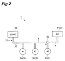
Fig. 2 is a diagram simply illustrating the diesel engine illustrated inFig. 1 . -
Fig. 3 is a graph illustrating the time history of the flow rate of exhaust gas that is discharged from respective cylinders illustrated inFig. 2 . -
Fig. 4 is a diagram simply illustrating an example of a diesel engine of which the layout of an exhaust passage, an EGR passage, and a fuel addition valve is different from that of the first embodiment, as a comparative example. -
Fig. 5 is a graph illustrating the analysis results of the time history of the concentration of added fuel that flows in the EGR passage. -
Fig. 6 is a diagram illustrating the schematic structure of a diesel engine as an internal combustion engine according to a second embodiment. -
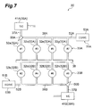
Fig. 7 is a diagram simply illustrating the diesel engine illustrated inFig. 6 . -
Fig. 8 is a graph illustrating the time history of the flow rate of exhaust gas that is discharged from each cylinder illustrated inFig. 7 . -
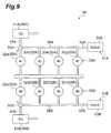
Fig. 9 is a diagram simply illustrating a modification of the diesel engine as the internal combustion engine according to the second embodiment. - Embodiments of the invention will be described in detail below with reference to the drawings. Meanwhile, the same elements or equivalent elements are denoted in the drawings by the same reference numerals and the repeated description thereof will be omitted.
-
Fig. 1 is a diagram illustrating the schematic structure of a diesel engine as an internal combustion engine according to a first embodiment. InFig. 1 , a diesel engine (hereinafter, simply referred to as an engine) 1 that is an internal combustion engine according to this embodiment is an in-line three-cylinder diesel engine that is mounted on a vehicle. - The
engine 1 includes anengine body 2. Theengine body 2 includes three cylinders 3 (a #1cylinder 3a, a #2cylinder 3b, and a #3cylinder 3c) that are arranged in one direction and threeinjectors 4 that inject fuel into combustion chambers of thecylinders 3, respectively. A common rail (not illustrated), which stores fuel, is connected to therespective injectors 4. - An
intake passage 5, which allows air to be taken into the combustion chambers of therespective cylinders 3, is connected to one side of theengine body 2 through anintake manifold 6. Anexhaust passage 7, through which exhaust gas generated in the combustion chambers of therespective cylinders 3 is discharged, is connected to the other side of theengine body 2 through anexhaust manifold 8. Also as illustrated inFig. 2 , theexhaust passage 7 is connected to a portion of theexhaust manifold 8 that corresponds to the #3cylinder 3c positioned at one end among therespective cylinders 3. - Further, the
engine 1 includes aturbocharger 9 for pressurizing air, which is to be taken into the combustion chambers of therespective cylinders 3, by the energy of exhaust gas generated in the combustion chambers of therespective cylinders 3. Theturbocharger 9 includes acompressor 10 that is provided on theintake passage 5 and aturbine 11 that is provided on theexhaust passage 7. - An
air cleaner 13 is provided on theintake passage 5 on the upstream side of thecompressor 10. Anintercooler 14 and athrottle valve 15 are provided on theintake passage 5 on the downstream side of thecompressor 10. Theintake passage 5, theintake manifold 6, thecompressor 10, theair cleaner 13, theintercooler 14, and thethrottle valve 15 form anintake system 16. - A diesel particulate filter (DPF) 17 and a NOx reduction catalyst 18 are provided on the
exhaust passage 7 on the downstream side of theturbine 11. Theexhaust passage 7, theexhaust manifold 8, theturbine 11, theDPF 17, and the NOx reduction catalyst 18 form anexhaust system 19. - A
fuel addition valve 20, which adds fuel to exhaust gas generated in the combustion chambers of therespective cylinders 3, is mounted on theengine body 2. Fuel is a reducing agent that is used to purify NOx by the NOx reduction catalyst 18. Also as illustrated inFig. 2 , thefuel addition valve 20 is disposed at a portion that corresponds to the #3cylinder 3c positioned at one end (which is close to the exhaust passage 7) among therespective cylinders 3. Thefuel addition valve 20 is controlled by a controller (not illustrated) so as to add fuel to theexhaust passage 7 when gas is exhausted from the #3cylinder 3c after the explosion of the #3cylinder 3c. - Further, the
engine 1 includes an exhaust gas recirculation system (EGR system) 21 for recirculating a part of exhaust gas, which is generated in the combustion chambers of therespective cylinders 3, in the combustion chambers of therespective cylinders 3 as exhaust gas recirculation gas (EGR gas). - The
EGR system 21 includes an exhaust gas recirculation passage (EGR passage) 22 that connects theexhaust manifold 8 to theintake manifold 6 and allows the EGR gas to return to therespective cylinders 3, anEGR cooler 23 that is provided on theEGR passage 22 and cools the EGR gas flowing in theEGR passage 22, and anEGR valve 24 that is provided on theEGR passage 22 on the downstream side of theEGR cooler 23 and adjusts the flow rate of the EGR gas returning to theintake manifold 6 from theexhaust manifold 8. - Also as illustrated in
Fig. 2 , one end of theEGR passage 22 is connected to a portion of theexhaust manifold 8 that corresponds to the #1cylinder 3a positioned at the other end among therespective cylinders 3. Accordingly, a portion, to which the EGR gas is introduced, of theEGR passage 22 is most away from thefuel addition valve 20. The other end of theEGR passage 22 is connected to the upstream portion of theintake manifold 6. Meanwhile, the other end of theEGR passage 22 may be connected to theintake passage 5. - In the above-mentioned
engine 1, the explosion order of therespective cylinders 3 is the order of the #1cylinder 3a, the #2cylinder 3b, and the #3cylinder 3c. That is, after the explosion of the #3cylinder 3c that is positioned at one end (which is close to the exhaust passage 7) among therespective cylinders 3, the #1cylinder 3a that is positioned at the other end (which is close to the EGR passage 22) among therespective cylinders 3 explodes. After that, the #2cylinder 3b, which is adjacent to the #1cylinder 3a positioned at the other end among therespective cylinders 3, explodes. - Since the
respective cylinders 3 explode in the order of the #1cylinder 3a, the #2cylinder 3b, and the #3cylinder 3c, the exhaust order of therespective cylinders 3 is also the order of the #1cylinder 3a, the #2cylinder 3b, and the #3cylinder 3c as illustrated inFig. 3. Fig. 3 is a graph illustrating the time history of the flow rate of exhaust gas that is discharged from the respective cylinders. Meanwhile, inFig. 3 , a crank angle becomes 0° when the #1cylinder 3a reaches a compression top dead center. As known fromFig. 3 , gas is exhausted from the #1cylinder 3a after gas is exhausted from the #3cylinder 3c. When gas is exhausted from the #3cylinder 3c, fuel is added from thefuel addition valve 20. A fuel addition period X is a period in which a crank angle is changed by a predetermined angle (for example, 100°) from the point of time when gas starts to be exhausted from the #3cylinder 3c. -
Fig. 4 is a diagram simply illustrating an example of an engine of which the layout of anexhaust passage 7, anEGR passage 22, and afuel addition valve 20 is different from that of the first embodiment, as a comparative example. InFig. 4 , theexhaust passage 7 is connected to a portion corresponding to a #1cylinder 3a. TheEGR passage 22 is connected to a portion corresponding to a #3cylinder 3c. Thefuel addition valve 20 is connected to a portion corresponding to the #1cylinder 3a. The explosion order of therespective cylinders 3 is the order of the #1cylinder 3a, the #2cylinder 3b, and the #3cylinder 3c. Thefuel addition valve 20 adds fuel when gas is exhausted from the #1cylinder 3 a. - In the exhaust stroke of the #1
cylinder 3a, most of exhaust gas generated in the #1cylinder 3 a flows in theexhaust passage 7 and a part of the exhaust gas flows in theEGR passage 22 through theexhaust manifold 8. Further, fuel is added from thefuel addition valve 20 in the exhaust stroke of the #1cylinder 3a. Then, the added fuel flows in theexhaust passage 7 and flows in theEGR passage 22 through theexhaust manifold 8. - After that, in the exhaust stroke of the #2
cylinder 3b, most of exhaust gas generated in the #2cylinder 3b flows in theexhaust passage 7 through theexhaust manifold 8 and a part of the exhaust gas flows in theEGR passage 22 through theexhaust manifold 8. At this time, the added fuel, which remains in theexhaust manifold 8 between the #2cylinder 3b and the #3cylinder 3c, is pushed toward theEGR passage 22 by the exhaust gas. Accordingly, since the amount of the added fuel flowing in theEGR passage 22 is increased, the added fuel is solidified and deposited on theEGR cooler 23 and theEGR valve 24. For this reason, there is a concern that the clogging or the like of theEGR cooler 23 and theEGR valve 24 may occur. - In contrast, in this embodiment, as illustrated in
Fig. 2 , theexhaust passage 7 is connected to a portion of theexhaust manifold 8 that corresponds to the #3cylinder 3c positioned at one end among therespective cylinders 3. TheEGR passage 22 is connected to a portion of theexhaust manifold 8 that corresponds to the #1cylinder 3a positioned at the other end among therespective cylinders 3. Thefuel addition valve 20 is disposed at a portion that corresponds to the #3cylinder 3c positioned at one end among therespective cylinders 3, and adds fuel when gas is exhausted from the #3cylinder 3c. Further, after the explosion of the #3cylinder 3c that is positioned at one end among therespective cylinders 3, the #1cylinder 3a that is positioned at the other end among therespective cylinders 3 explodes. After that, the #2cylinder 3b, which is adjacent to the #1cylinder 3a positioned at the other end among therespective cylinders 3, explodes. - In the exhaust stroke of the #3
cylinder 3c, most of exhaust gas generated in the #3cylinder 3c flows in theexhaust passage 7 and a part of the exhaust gas flows in theEGR passage 22 through theexhaust manifold 8. Further, fuel is added from thefuel addition valve 20 in the exhaust stroke of the #3cylinder 3c. Then, the added fuel flows in theexhaust passage 7 and flows in theEGR passage 22 through theexhaust manifold 8. - After that, in the exhaust stroke of the #1
cylinder 3a, most of exhaust gas generated in the #1cylinder 3 a flows in theexhaust passage 7 through theexhaust manifold 8 and a part of the exhaust gas flows in theEGR passage 22. At this time, the added fuel, which remains in theexhaust manifold 8 between the #1cylinder 3a and the #3cylinder 3c, is pushed back toward theexhaust passage 7 by the exhaust gas. For this reason, the flow of the added fuel in theEGR passage 22 is suppressed. Accordingly, it is possible to reduce the amount of the added fuel flowing to theEGR system 21. - After that, in the exhaust stroke of the #2
cylinder 3b, most of exhaust gas generated in the #2cylinder 3b flows in theexhaust passage 7 through theexhaust manifold 8 and a part of the exhaust gas flows in theEGR passage 22 through theexhaust manifold 8. At this time, the added fuel, which remains in theexhaust manifold 8 between the #2cylinder 3b and the #3cylinder 3c, is pushed back toward theexhaust passage 7 by the exhaust gas. For this reason, the flow of the added fuel in theEGR passage 22 is further suppressed. Accordingly, it is possible to further reduce the amount of the added fuel flowing to theEGR system 21. - Therefore, according to this embodiment, it is possible to prevent the occurrence of clogging or the like of the
EGR cooler 23 and theEGR valve 24 by reducing the amount of the added fuel to be deposited on theEGR cooler 23 and theEGR valve 24. As a result, it is possible to improve the performance of theEGR system 21. -
Fig. 5 is a graph illustrating the analysis results of the time history of the concentration of the added fuel that flows in theEGR passage 22. A broken line P ofFig. 5 indicates the results of the comparative example illustrated inFig. 4 , and a solid line Q ofFig. 5 indicates the results of this embodiment illustrated inFig. 2 . Meanwhile, the crank angles of the broken line P and the solid line Q are offset from each other inFig. 5 so that the broken line P and the solid line Q are easily compared with each other. - As known from
Fig. 5 , when fuel is added from thefuel addition valve 20, the concentration of the added fuel flowing in theEGR passage 22 becomes high immediately after the addition of fuel and the concentration of the added fuel flowing in theEGR passage 22 then becomes low. However, since the added fuel is pushed toward theEGR passage 22 by the exhaust gas generated in the #2cylinder 3b in the comparative example, slight added fuel is present in theEGR passage 22 even after that. Meanwhile, since the added fuel is pushed back toward theexhaust passage 7 by the exhaust gas generated in the #1cylinder 3a in this embodiment, the added fuel is hardly present in theEGR passage 22. Accordingly, the concentration of the added fuel flowing in theEGR passage 22 in this embodiment becomes lower than that in the comparative example. -
Fig. 6 is a diagram illustrating the schematic structure of a diesel engine as an internal combustion engine according to a second embodiment. InFig. 6 , a diesel engine (hereinafter, simply referred to as an engine) 30 that is an internal combustion engine according to this embodiment is a V-type eight-cylinder diesel engine that is mounted on a vehicle. - The
engine 30 includesengine bodies engine body 31A includes aright bank 33A that includes fourcylinders 32A (a #1cylinder 32a, a #3cylinder 32c, a #5cylinder 32e, and a #7cylinder 32g) arranged in one direction, and fourinjectors 34A that inject fuel into combustion chambers of thecylinders 32A, respectively. Theengine body 31B includes aleft bank 33B that includes fourcylinders 32B (a #2cylinder 32b, a #4cylinder 32d, a #6cylinder 32f, and a #8cylinder 32h) arranged in one direction, and fourinjectors 34B that inject fuel into combustion chambers of thecylinders 32B, respectively. -
Intake passages respective cylinders engine bodies intake manifold 6.Exhaust passages respective cylinders engine bodies exhaust manifolds Fig. 7 , theexhaust passage 37A is connected to a portion of theexhaust manifold 38A that corresponds to the #1cylinder 32a positioned at one end among therespective cylinders 32A. Also as illustrated inFig. 7 , theexhaust passage 37B is connected to a portion of theexhaust manifold 38B that corresponds to the #8cylinder 32h positioned at one end among therespective cylinders 32B. - Further, the
engine 30 includesturbochargers respective cylinders respective cylinders turbochargers compressors intake passages turbines exhaust passages - The
intake passages common intake passage 35. Anair cleaner 43 is provided on thecommon intake passage 35.Intercoolers throttle valves intake passages compressors common intake passage 35, theintake passage 35A, theintake manifold 36, thecompressor 40A, theair cleaner 43, theintercooler 44A, and thethrottle valve 45A form anintake system 46A. Thecommon intake passage 35, theintake passage 35B, theintake manifold 36, thecompressor 40B, theair cleaner 43, theintercooler 44B, and thethrottle valve 45B form anintake system 46B. -
DPFs reduction catalysts exhaust passages turbines exhaust passages exhaust manifolds turbines DPFs form exhaust systems -
Fuel addition valves respective cylinders engine bodies Fig. 7 , thefuel addition valve 50A is disposed at a portion that corresponds to the #1cylinder 32a positioned at one end (which is close to theexhaust passage 37A) among therespective cylinders 32A. Thefuel addition valve 50A is controlled by a controller (not illustrated) so as to add fuel to theexhaust passage 37A when gas is exhausted from the #1cylinder 32a after the explosion of the #1cylinder 32a. - Also as illustrated in
Fig. 7 , thefuel addition valve 50B is disposed at a portion that corresponds to the #8cylinder 32h positioned at one end (which is close to theexhaust passage 37B) among therespective cylinders 32B. Thefuel addition valve 50B is controlled by a controller (not illustrated) so as to add fuel to theexhaust passage 37B when gas is exhausted from the #8cylinder 32h after the explosion of the #8cylinder 32h. - Further, the
engine 30 includes exhaust gas recirculation systems (EGR systems) 51A and 51B for recirculating a part of exhaust gas, which is generated in the combustion chambers of therespective cylinders respective cylinders - The
EGR systems exhaust manifolds intake passages respective cylinders EGR coolers EGR passages EGR passages EGR valves EGR passages EGR coolers intake passages exhaust manifolds - Also as illustrated in
Fig. 7 , one end of theEGR passage 52A is connected to a portion of theexhaust manifold 38A that corresponds to the #7cylinder 32g positioned at the other end among therespective cylinders 32A. Accordingly, a portion, to which the EGR gas is introduced, of theEGR passage 52A is most away from thefuel addition valve 50A. The other end of theEGR passage 52A is connected to a portion of theintake passage 35A between theintake manifold 36 and thethrottle valve 45A. Meanwhile, the other end of theEGR passage 52A may be connected to theintake manifold 36. - Also as illustrated in
Fig. 7 , one end of theEGR passage 52B is connected to a portion of theexhaust manifold 38B that corresponds to the #2cylinder 32b positioned at the other end among therespective cylinders 32B. Accordingly, a portion, to which the EGR gas is introduced, of theEGR passage 52B is most away from thefuel addition valve 50B. The other end of theEGR passage 52B is connected to a portion of theintake passage 35B between theintake manifold 36 and thethrottle valve 45B. Meanwhile, the other end of theEGR passage 52B may be connected to theintake manifold 36. - In the above-mentioned
engine 30, the explosion order of therespective cylinders cylinder 32a, the #2cylinder 32b, the #7cylinder 32g, the #3cylinder 32c, the #4cylinder 32d, the #5cylinder 32e, the #6cylinder 32f, and the #8cylinder 32h. That is, the explosion of thebanks - Here, the explosion order of the
respective cylinders 32A of theright bank 33A is the order of the #1cylinder 32a, the #7cylinder 32g, the #3cylinder 32c, and the #5cylinder 32e. That is, after the explosion of the #1cylinder 32a that is positioned at one end (which is close to theexhaust passage 37A) among therespective cylinders 32A, the #7cylinder 32g that is positioned at the other end (which is close to theEGR passage 52A) among therespective cylinders 32A explodes. Then, the #3cylinder 32c and the #5cylinder 32e sequentially explode. - Since the
respective cylinders 32A explode in the order of the #1cylinder 32a, the #7cylinder 32g, the #3cylinder 32c, and the #5cylinder 32e, the exhaust order of therespective cylinders 32A is also the order of the #1cylinder 32a, the #7cylinder 32g, the #3cylinder 32c, and the #5cylinder 32e as illustrated inFig. 8A. Fig. 8A is a graph illustrating the time history of the flow rate of exhaust gas that is discharged from therespective cylinders 32A of theright bank 33A. As known fromFig. 8A , gas is exhausted from the #7cylinder 32g after gas is exhausted from the #1cylinder 32a. When gas is exhausted from the #1cylinder 32a, fuel is added from thefuel addition valve 50A. A fuel addition period X1 is a period in which a crank angle is changed by a predetermined angle from the point of time when gas starts to be exhausted from the #1cylinder 32a. - The explosion order of the
respective cylinders 32B of theleft bank 33B is the order of the #2cylinder 32b, the #4cylinder 32d, the #6cylinder 32f, and the #8cylinder 32h. That is, after the explosion of the #8cylinder 32h that is positioned at one end (which is close to theexhaust passage 37B) among therespective cylinders 32B, the #2cylinder 32b that is positioned at the other end (which is close to theEGR passage 52B) among therespective cylinders 32B explodes. Then, the #4cylinder 32d that is adjacent to the #2cylinder 32b positioned at the other end among therespective cylinders 32B explodes. Accordingly, after the explosion of the #2cylinder 32b that is positioned at the other end among therespective cylinders 32B, the #4cylinder 32d and the #6cylinder 32f explode in turn toward one side (theexhaust passage 37B) from the other side (theEGR passage 52B). - Since the
respective cylinders 32B explode in the order of the #2cylinder 32b, the #4cylinder 32d, the #6cylinder 32f, and the #8cylinder 32h, the exhaust order of therespective cylinders 32B is also the order of the #2cylinder 32b, the #4cylinder 32d, the #6cylinder 32f, and the #8cylinder 32h as illustrated inFig. 8B. Fig. 8B is a graph illustrating the time history of the flow rate of exhaust gas that is discharged from therespective cylinders 32B of theleft bank 33B. As known fromFig. 8B , gas is exhausted from the #2cylinder 32b after gas is exhausted from the #8cylinder 32h. When gas is exhausted from the #8cylinder 32h, fuel is added from thefuel addition valve 50B. A fuel addition period X2 is a period in which a crank angle is changed by a predetermined angle from the point of time when gas starts to be exhausted from the #8cylinder 32h. - In the exhaust stroke of the #1
cylinder 32a of theright bank 33A, most of exhaust gas generated in the #1cylinder 32a flows in theexhaust passage 37A and a part of the exhaust gas flows in theEGR passage 52A through theexhaust manifold 38A. Further, fuel is added from thefuel addition valve 50A in the exhaust stroke of the #1cylinder 32a. Then, the added fuel flows in theexhaust passage 37A and flows in theEGR passage 52A through theexhaust manifold 38A. - After that, in the exhaust stroke of the #7
cylinder 32g, most of exhaust gas generated in the #7cylinder 32g flows in theexhaust passage 37A through theexhaust manifold 38A and a part of the exhaust gas flows in theEGR passage 52A. At this time, the added fuel, which remains in theexhaust manifold 38A between the #1cylinder 32a and the #7cylinder 32g, is pushed back toward theexhaust passage 37A by the exhaust gas. - After that, in the exhaust stroke of the #3
cylinder 32c, most of exhaust gas generated in the #3cylinder 32c flows in theexhaust passage 37A through theexhaust manifold 38A and a part of the exhaust gas flows in theEGR passage 52A through theexhaust manifold 38A. At this time, the added fuel, which remains in theexhaust manifold 38A between the #1cylinder 32a and the #3cylinder 32c, is pushed back toward theexhaust passage 37A by the exhaust gas. - After that, in the exhaust stroke of the #5
cylinder 32e, most of exhaust gas generated in the #5cylinder 32e flows in theexhaust passage 37A through theexhaust manifold 38A and a part of the exhaust gas flows in theEGR passage 52A through theexhaust manifold 38A. - In the exhaust stroke of the #8
cylinder 32h of theleft bank 33B, most of exhaust gas generated in the #8cylinder 32h flows in theexhaust passage 37B and a part of the exhaust gas flows in theEGR passage 52B through theexhaust manifold 38B. Further, fuel is added from thefuel addition valve 50B in the exhaust stroke of the #8cylinder 32h. Then, the added fuel flows in theexhaust passage 37B and flows in theEGR passage 52B through theexhaust manifold 38B. - After that, in the exhaust stroke of the #2
cylinder 32b, most of exhaust gas generated in the #2cylinder 32b flows in theexhaust passage 37B through theexhaust manifold 38B and a part of the exhaust gas flows in theEGR passage 52B. At this time, the added fuel, which remains in theexhaust manifold 38B between the #2cylinder 32b and the #8cylinder 32h, is pushed back toward theexhaust passage 37B by the exhaust gas. - After that, in the exhaust stroke of the #4
cylinder 32d, most of exhaust gas generated in the #4cylinder 32d flows in theexhaust passage 37B through theexhaust manifold 38B and a part of the exhaust gas flows in theEGR passage 52B through theexhaust manifold 38B. At this time, the added fuel, which remains in theexhaust manifold 38B between the #4cylinder 32d and the #8cylinder 32h, is pushed back toward theexhaust passage 37B by the exhaust gas. - After that, in the exhaust stroke of the #6
cylinder 32f, most of exhaust gas generated in the #6cylinder 32f flows in theexhaust passage 37B through theexhaust manifold 38B and a part of the exhaust gas flows in theEGR passage 52B through theexhaust manifold 38B. At this time, the added fuel, which remains in theexhaust manifold 38B between the #6cylinder 32f and the #8cylinder 32h, is pushed back toward theexhaust passage 37B by the exhaust gas. - As described above, according to this embodiment, in the
right bank 33A, theexhaust passage 37A is connected to a portion of theexhaust manifold 38A that corresponds to the #1cylinder 32a positioned at one end among therespective cylinders 32A. TheEGR passage 52A is connected to a portion of theexhaust manifold 38A that corresponds to the #7cylinder 32g positioned at the other end among therespective cylinders 32A. Thefuel addition valve 50A is disposed at a portion that corresponds to the #1cylinder 32a positioned at one end among therespective cylinders 32A, and adds fuel when gas is exhausted from the #1cylinder 32a. Further, after the explosion of the #1cylinder 32a that is positioned at one end among therespective cylinders 32A, the #7cylinder 32g that is positioned at the other end among therespective cylinders 32A explodes. For this reason, as described above, the added fuel, which remains in theexhaust manifold 38A between the #1cylinder 32a and the #7cylinder 32g, is pushed toward theexhaust passage 37A by the exhaust gas. Accordingly, the flow of the added fuel in theEGR passage 52A is suppressed. Therefore, it is possible to reduce the amount of the added fuel flowing to theEGR system 51A. - In the
left bank 33B, theexhaust passage 37B is connected to a portion of theexhaust manifold 38B that corresponds to the #8cylinder 32h positioned at one end among therespective cylinders 32B. TheEGR passage 52B is connected to a portion of theexhaust manifold 38B that corresponds to the #2cylinder 32b positioned at the other end among therespective cylinders 32B. Thefuel addition valve 50B is disposed at a portion that corresponds to the #8cylinder 32h positioned at one end among therespective cylinders 32B, and adds fuel when gas is exhausted from the #8cylinder 32h. Further, after the explosion of the #8cylinder 32h that is positioned at one end among therespective cylinders 32B, the #2cylinder 32b that is positioned at the other end among therespective cylinders 32B explodes. For this reason, as described above, the added fuel, which remains in theexhaust manifold 38B between the #2cylinder 32b and the #8cylinder 32h, is pushed toward theexhaust passage 37B by the exhaust gas. Accordingly, the flow of the added fuel in theEGR passage 52B is suppressed. Therefore, it is possible to reduce the amount of the added fuel flowing to theEGR system 51B. - Furthermore, in the
left bank 33B, the #4cylinder 32d adjacent to the #2cylinder 32b explodes after the explosion of the #2cylinder 32b that is positioned at the other end among therespective cylinders 32B. For this reason, as described above, the added fuel, which remains in theexhaust manifold 38B between the #4cylinder 32d and the #8cylinder 32h, is pushed back toward theexhaust passage 37B by the exhaust gas. Accordingly, the flow of the added fuel in theEGR passage 52B is further suppressed. Therefore, it is possible to further reduce the amount of the added fuel flowing to theEGR system 51B. - In addition, in the
left bank 33B, the #4cylinder 32d and the #6cylinder 32f explode in turn toward one side from the other side after the explosion of the #2cylinder 32b that is positioned at the other end among therespective cylinders 32B. Accordingly, since the added fuel is sequentially and effectively pushed back toward theexhaust passage 37B by the exhaust gas that is generated in therespective cylinders 32B, it is possible to further reduce the amount of the added fuel flowing to theEGR system 51B. -
Fig. 9 is a diagram simply illustrating a modification of thediesel engine 30 as the internal combustion engine according to the second embodiment. - In
Fig. 9 , in aright bank 33A, theexhaust passage 37A is connected to a portion of theexhaust manifold 38A that corresponds to the #1cylinder 32a positioned at one end among therespective cylinders 32A. TheEGR passage 52A is connected to a portion of theexhaust manifold 38A that corresponds to the #7cylinder 32g positioned at the other end among therespective cylinders 32A. Thefuel addition valve 50A is disposed at a portion that corresponds to the #1cylinder 32a positioned at one end (which is close to theexhaust passage 37A) among therespective cylinders 32A. Thefuel addition valve 50A adds fuel to theexhaust passage 37A when gas is exhausted from the #1cylinder 32a after the explosion of the #1cylinder 32a. - In the
left bank 33B, theexhaust passage 37B is connected to a portion of theexhaust manifold 38B that corresponds to the #2cylinder 32b positioned at one end among therespective cylinders 32B. TheEGR passage 52B is connected to a portion of theexhaust manifold 38B that corresponds to the 8cylinder 32h positioned at the other end among therespective cylinders 32B. Thefuel addition valve 50B is disposed at a portion that corresponds to the #2cylinder 32b positioned at one end (which is close to theexhaust passage 37B) among therespective cylinders 32B. Thefuel addition valve 50B adds fuel to theexhaust passage 37B when gas is exhausted from the #2cylinder 32b after the explosion of the #2cylinder 32b. - In the
engine 30, the explosion order of therespective cylinders cylinder 32a, the #2cylinder 32b, the #7cylinder 32g, the #8cylinder 32h, the #4cylinder 32d, the #5cylinder 32e, the #6cylinder 32f, and the #3cylinder 32c. That is, the explosion of thebanks - Here, the explosion order of the
respective cylinders 32A of theright bank 33A is the order of the #1cylinder 32a, the #7cylinder 32g, the #5cylinder 32e, and the #3cylinder 32c. That is, after the explosion of the #1cylinder 32a that is positioned at one end (which is close to theexhaust passage 37A) among therespective cylinders 32A, the #7cylinder 32g that is positioned at the other end (which is close to theEGR passage 52A) among therespective cylinders 32A explodes. Then, the #5cylinder 32e, which is adjacent to the #7cylinder 32g positioned at the other end among therespective cylinders 32A, explodes. Accordingly, after the explosion of the #7cylinder 32g that is positioned at the other end among therespective cylinders 32A, the #5cylinder 32e and the #3cylinder 32c explode in turn toward one side (theexhaust passage 37A) from the other side (theEGR passage 52A). - The explosion order of the
respective cylinders 32B of theleft bank 33B is the order of the #2cylinder 32b, the #8cylinder 32h, the #4cylinder 32d, and the #6cylinder 32f. That is, after the explosion of the #2cylinder 32b that is positioned at one end (which is close to theexhaust passage 37B) among therespective cylinders 32B, the #8cylinder 32h that is positioned at the other end (which is close to theEGR passage 52B) among therespective cylinders 32B explodes. Then, the #4cylinder 32d and the #6cylinder 32f sequentially explode. - In the exhaust stroke of the #1
cylinder 32a of theright bank 33A, most of exhaust gas generated in the #1cylinder 32a flows in theexhaust passage 37A and a part of the exhaust gas flows in theEGR passage 52A through theexhaust manifold 38A. Further, fuel is added from the fuel addition valve 20A in the exhaust stroke of the #1cylinder 32a. Then, the added fuel flows in theexhaust passage 37A and flows in theEGR passage 52A through theexhaust manifold 38A. - After that, in the exhaust stroke of the #7
cylinder 32g, most of exhaust gas generated in the #7cylinder 32g flows in theexhaust passage 37A through theexhaust manifold 38A and a part of the exhaust gas flows in theEGR passage 52A. At this time, the added fuel, which remains in theexhaust manifold 38B between the #1cylinder 32a and the #7cylinder 32g, is pushed back toward theexhaust passage 37A by the exhaust gas. - After that, in the exhaust stroke of the #5
cylinder 32e, most of exhaust gas generated in the #5cylinder 32e flows in theexhaust passage 37A through theexhaust manifold 38A and a part of the exhaust gas flows in theEGR passage 52A through theexhaust manifold 38A. At this time, the added fuel, which remains in theexhaust manifold 38A between the #1cylinder 32a and the #5cylinder 32e, is pushed back toward theexhaust passage 37A by the exhaust gas. - After that, in the exhaust stroke of the #3
cylinder 32c, most of exhaust gas generated in the #3cylinder 32c flows in theexhaust passage 37A through theexhaust manifold 38A and a part of the exhaust gas flows in theEGR passage 52A through theexhaust manifold 38A. At this time, the added fuel, which remains in theexhaust manifold 38A between the #1cylinder 32a and the #3cylinder 32c, is pushed back toward theexhaust passage 37A by the exhaust gas. - In the exhaust stroke of the #2
cylinder 32b of theleft bank 33B, most of exhaust gas generated in the #2cylinder 32b flows in theexhaust passage 37B and a part of the exhaust gas flows in theEGR passage 52B through theexhaust manifold 38B. Further, fuel is added from thefuel addition valve 50B in the exhaust stroke of the #2cylinder 32b. Then, the added fuel flows in theexhaust passage 37B and flows in theEGR passage 52B through theexhaust manifold 38B. - After that, in the exhaust stroke of the #8
cylinder 32h, most of exhaust gas generated in the #8cylinder 32h flows in theexhaust passage 37B through theexhaust manifold 38B and a part of the exhaust gas flows in theEGR passage 52B. At this time, the added fuel, which remains in theexhaust manifold 38B between the #2cylinder 32b and the #8cylinder 32h, is pushed back toward theexhaust passage 37B by the exhaust gas. - After that, in the exhaust stroke of the #4
cylinder 32d, most of exhaust gas generated in the #4cylinder 32d flows in theexhaust passage 37B through theexhaust manifold 38B and a part of the exhaust gas flows in theEGR passage 52B through theexhaust manifold 38B. At this time, the added fuel, which remains in theexhaust manifold 38B between the #2cylinder 32b and the #4cylinder 32d, is pushed back toward theexhaust passage 37B by the exhaust gas. - After that, in the exhaust stroke of the #6
cylinder 32f, most of exhaust gas generated in the #6cylinder 32f flows in theexhaust passage 37B through theexhaust manifold 38B and a part of the exhaust gas flows in theEGR passage 52B through theexhaust manifold 38B. - It is possible to reduce the amount of the added fuel flowing to the
EGR systems - Meanwhile, the invention is not limited to the above-mentioned embodiments. For example, in the eight-cylinder diesel engine of the second embodiment, the explosion order of the
respective cylinders 32A of theright bank 33A may be the order of the #1cylinder 32a, the #7cylinder 32g, the #5cylinder 32e, and the #3cylinder 32c, and the explosion order of therespective cylinders 32B of theleft bank 33B may be the order of the #2cylinder 32b, the #4cylinder 32d, the #6cylinder 32f, and the #8cylinder 32h. - Further, the internal combustion engines of the embodiments have been an in-line three-cylinder diesel engine and a eight-cylinder diesel engine. However, the type of the diesel engine is not particularly limited to these diesel engines and the diesel engine may include a plurality of cylinders that are arranged in one direction as in an in-line four-cylinder diesel engine or a six-cylinder diesel engine. For example, in the in-line four-cylinder diesel engine, the explosion order of the respective cylinders is the order of the #1 cylinder, the #4 cylinder, the #3 cylinder, and the #2 cylinder.
- Furthermore, the internal combustion engines of the embodiments have been diesel engines, but the invention may also be applied to a gasoline engine and the like.
A diesel engine includes an exhaust passage through which exhaust gas generated in plural cylinders is discharged, a fuel addition valve adding fuel to the exhaust gas, and an exhaust gas recirculation system including an exhaust gas recirculation passage that allows a part of the exhaust gas to return to the cylinders as exhaust gas recirculation gas. The exhaust passage is connected to a portion of an exhaust manifold corresponding to the #3 cylinder positioned at one end among the plurality of cylinders, the fuel addition valve is disposed at a portion corresponding to the #3 cylinder and adds the fuel when gas is exhausted from the #3 cylinder, the exhaust gas recirculation passage is connected to a portion of the exhaust manifold corresponding to the #1 cylinder positioned at the other end among the plurality of cylinders, and the #1 cylinder explodes after the explosion of the #3 cylinder.
Claims (3)
- An internal combustion engine comprising:an engine body that includes a plurality of cylinders arranged in one direction;an intake passage that is connected to the engine body through an intake manifold and allows air to be taken into the cylinders;an exhaust passage which is connected to the engine body through an exhaust manifold and through which exhaust gas generated in the cylinders is discharged;a fuel addition valve that adds fuel to the exhaust gas; andan exhaust gas recirculation system including an exhaust gas recirculation passage that connects the exhaust manifold to an intake system including the intake manifold and the intake passage and allows a part of the exhaust gas to return to the cylinders as exhaust gas recirculation gas,wherein the exhaust passage is connected to a portion of the exhaust manifold that corresponds to the cylinder positioned at one end among the plurality of cylinders,the fuel addition valve is disposed at a portion that corresponds to the cylinder positioned at the one end and adds the fuel when gas is exhausted from the cylinder positioned at the one end,the exhaust gas recirculation passage is connected to a portion of the exhaust manifold that corresponds to the cylinder positioned at the other end among the plurality of cylinders, andthe cylinder positioned at the other end explodes after the explosion of the cylinder positioned at the one end.
- The internal combustion engine according to claim 1,
wherein the cylinder, which is adjacent to the cylinder positioned at the other end, explodes after the explosion of the cylinder positioned at the other end. - The internal combustion engine according to claim 2,
wherein the cylinders explode in turn toward the one side from the other side after the explosion of the cylinder positioned at the other end.
Applications Claiming Priority (1)
| Application Number | Priority Date | Filing Date | Title |
|---|---|---|---|
| JP2015072984A JP2016191373A (en) | 2015-03-31 | 2015-03-31 | Internal combustion engine |
Publications (1)
| Publication Number | Publication Date |
|---|---|
| EP3075999A1 true EP3075999A1 (en) | 2016-10-05 |
Family
ID=55628873
Family Applications (1)
| Application Number | Title | Priority Date | Filing Date |
|---|---|---|---|
| EP16162152.9A Withdrawn EP3075999A1 (en) | 2015-03-31 | 2016-03-24 | Internal combustion engine |
Country Status (2)
| Country | Link |
|---|---|
| EP (1) | EP3075999A1 (en) |
| JP (1) | JP2016191373A (en) |
Citations (3)
| Publication number | Priority date | Publication date | Assignee | Title |
|---|---|---|---|---|
| JP2001280125A (en) | 2000-03-31 | 2001-10-10 | Toyota Motor Corp | Exhaust gas purification device for internal combustion engine |
| EP1291498A2 (en) * | 2001-09-11 | 2003-03-12 | Toyota Jidosha Kabushiki Kaisha | Emission control system for internal combustion engine |
| DE102006049392A1 (en) * | 2005-11-04 | 2007-05-10 | Toyota Jidosha Kabushiki Kaisha, Toyota | Exhaust gas emission control system for internal combustion engine, has agent adding device and recirculation outlet arranged in exhaust gas channels, where large part of gas from channels is separately flowed to rotor without mixing |
Family Cites Families (4)
| Publication number | Priority date | Publication date | Assignee | Title |
|---|---|---|---|---|
| JP4577039B2 (en) * | 2005-02-18 | 2010-11-10 | トヨタ自動車株式会社 | Exhaust gas purification device for internal combustion engine |
| JP2007218140A (en) * | 2006-02-15 | 2007-08-30 | Toyota Industries Corp | Exhaust purification device and exhaust purification method |
| JP2007255371A (en) * | 2006-03-24 | 2007-10-04 | Daihatsu Motor Co Ltd | Injection control method of reducing agent for exhaust gas |
| JP4505441B2 (en) * | 2006-09-27 | 2010-07-21 | 株式会社豊田自動織機 | Exhaust gas purification device for internal combustion engine |
-
2015
- 2015-03-31 JP JP2015072984A patent/JP2016191373A/en active Pending
-
2016
- 2016-03-24 EP EP16162152.9A patent/EP3075999A1/en not_active Withdrawn
Patent Citations (3)
| Publication number | Priority date | Publication date | Assignee | Title |
|---|---|---|---|---|
| JP2001280125A (en) | 2000-03-31 | 2001-10-10 | Toyota Motor Corp | Exhaust gas purification device for internal combustion engine |
| EP1291498A2 (en) * | 2001-09-11 | 2003-03-12 | Toyota Jidosha Kabushiki Kaisha | Emission control system for internal combustion engine |
| DE102006049392A1 (en) * | 2005-11-04 | 2007-05-10 | Toyota Jidosha Kabushiki Kaisha, Toyota | Exhaust gas emission control system for internal combustion engine, has agent adding device and recirculation outlet arranged in exhaust gas channels, where large part of gas from channels is separately flowed to rotor without mixing |
Also Published As
| Publication number | Publication date |
|---|---|
| JP2016191373A (en) | 2016-11-10 |
Similar Documents
| Publication | Publication Date | Title |
|---|---|---|
| US7287378B2 (en) | Divided exhaust manifold system and method | |
| US8671920B2 (en) | Internal combustion engine | |
| US20110041495A1 (en) | Systems and methods for exhaust gas recirculation | |
| JP6599616B2 (en) | Method and system for exhaust gas recirculation | |
| US8439021B2 (en) | EGR system for an internal combustion engine | |
| JP4392689B2 (en) | Cylinder group individually controlled engine | |
| US11028791B2 (en) | Method and system for matching air flow in an exhaust gas recirculation system | |
| EP1766204B1 (en) | Arrangement for controlling exhaust pressure pulses at an internal combustion engine | |
| CN204175440U (en) | System for controlling an EGR system in an internal combustion engine | |
| JP4496248B2 (en) | Supercharged engine with EGR device | |
| JP2005054771A5 (en) | ||
| US20140109569A1 (en) | Exhaust gas recirculation system for engine | |
| US7275511B1 (en) | Intake manifold assembly | |
| US8234855B2 (en) | Exhaust gas purification device for internal combustion engine | |
| EP3514361A1 (en) | Multi-cylinder engine, and cylinder head | |
| JP2020002796A (en) | Multi-cylinder engine intake system | |
| JP2016191373A (en) | Internal combustion engine | |
| KR20190043388A (en) | Engine system | |
| EP3514362A1 (en) | Multi-cylinder engine, and cylinder head | |
| KR100528233B1 (en) | Hi-Pulse Turbo-Charging System for Multi-Cylinder Diesel Engine | |
| JP6032802B2 (en) | EGR device | |
| JP7151209B2 (en) | Intake system for multi-cylinder engine | |
| JP2016188627A (en) | Egr device of engine | |
| EP2434113A1 (en) | Particulate filter regeneration | |
| KR20160147467A (en) | Diesel engine |
Legal Events
| Date | Code | Title | Description |
|---|---|---|---|
| PUAI | Public reference made under article 153(3) epc to a published international application that has entered the european phase |
Free format text: ORIGINAL CODE: 0009012 |
|
| 17P | Request for examination filed |
Effective date: 20160324 |
|
| AK | Designated contracting states |
Kind code of ref document: A1 Designated state(s): AL AT BE BG CH CY CZ DE DK EE ES FI FR GB GR HR HU IE IS IT LI LT LU LV MC MK MT NL NO PL PT RO RS SE SI SK SM TR |
|
| AX | Request for extension of the european patent |
Extension state: BA ME |
|
| 17Q | First examination report despatched |
Effective date: 20170726 |
|
| GRAP | Despatch of communication of intention to grant a patent |
Free format text: ORIGINAL CODE: EPIDOSNIGR1 |
|
| INTG | Intention to grant announced |
Effective date: 20180212 |
|
| STAA | Information on the status of an ep patent application or granted ep patent |
Free format text: STATUS: THE APPLICATION IS DEEMED TO BE WITHDRAWN |
|
| 18D | Application deemed to be withdrawn |
Effective date: 20180623 |