EP3075980A1 - Engine - Google Patents
Engine Download PDFInfo
- Publication number
- EP3075980A1 EP3075980A1 EP16161734.5A EP16161734A EP3075980A1 EP 3075980 A1 EP3075980 A1 EP 3075980A1 EP 16161734 A EP16161734 A EP 16161734A EP 3075980 A1 EP3075980 A1 EP 3075980A1
- Authority
- EP
- European Patent Office
- Prior art keywords
- engine
- top cover
- operation part
- control unit
- side operation
- Prior art date
- Legal status (The legal status is an assumption and is not a legal conclusion. Google has not performed a legal analysis and makes no representation as to the accuracy of the status listed.)
- Granted
Links
Images


Classifications
-
- F—MECHANICAL ENGINEERING; LIGHTING; HEATING; WEAPONS; BLASTING
- F02—COMBUSTION ENGINES; HOT-GAS OR COMBUSTION-PRODUCT ENGINE PLANTS
- F02B—INTERNAL-COMBUSTION PISTON ENGINES; COMBUSTION ENGINES IN GENERAL
- F02B77/00—Component parts, details or accessories, not otherwise provided for
- F02B77/02—Surface coverings of combustion-gas-swept parts
-
- B—PERFORMING OPERATIONS; TRANSPORTING
- B60—VEHICLES IN GENERAL
- B60R—VEHICLES, VEHICLE FITTINGS, OR VEHICLE PARTS, NOT OTHERWISE PROVIDED FOR
- B60R13/00—Elements for body-finishing, identifying, or decorating; Arrangements or adaptations for advertising purposes
- B60R13/08—Insulating elements, e.g. for sound insulation
- B60R13/0838—Insulating elements, e.g. for sound insulation for engine compartments
-
- B—PERFORMING OPERATIONS; TRANSPORTING
- B63—SHIPS OR OTHER WATERBORNE VESSELS; RELATED EQUIPMENT
- B63H—MARINE PROPULSION OR STEERING
- B63H21/00—Use of propulsion power plant or units on vessels
- B63H21/36—Covers or casing arranged to protect plant or unit from marine environment
-
- F—MECHANICAL ENGINEERING; LIGHTING; HEATING; WEAPONS; BLASTING
- F02—COMBUSTION ENGINES; HOT-GAS OR COMBUSTION-PRODUCT ENGINE PLANTS
- F02B—INTERNAL-COMBUSTION PISTON ENGINES; COMBUSTION ENGINES IN GENERAL
- F02B77/00—Component parts, details or accessories, not otherwise provided for
- F02B77/11—Thermal or acoustic insulation
-
- F—MECHANICAL ENGINEERING; LIGHTING; HEATING; WEAPONS; BLASTING
- F02—COMBUSTION ENGINES; HOT-GAS OR COMBUSTION-PRODUCT ENGINE PLANTS
- F02F—CYLINDERS, PISTONS OR CASINGS, FOR COMBUSTION ENGINES; ARRANGEMENTS OF SEALINGS IN COMBUSTION ENGINES
- F02F1/00—Cylinders; Cylinder heads
- F02F1/24—Cylinder heads
-
- F—MECHANICAL ENGINEERING; LIGHTING; HEATING; WEAPONS; BLASTING
- F02—COMBUSTION ENGINES; HOT-GAS OR COMBUSTION-PRODUCT ENGINE PLANTS
- F02F—CYLINDERS, PISTONS OR CASINGS, FOR COMBUSTION ENGINES; ARRANGEMENTS OF SEALINGS IN COMBUSTION ENGINES
- F02F3/00—Pistons
- F02F3/28—Other pistons with specially-shaped head
-
- F—MECHANICAL ENGINEERING; LIGHTING; HEATING; WEAPONS; BLASTING
- F02—COMBUSTION ENGINES; HOT-GAS OR COMBUSTION-PRODUCT ENGINE PLANTS
- F02N—STARTING OF COMBUSTION ENGINES; STARTING AIDS FOR SUCH ENGINES, NOT OTHERWISE PROVIDED FOR
- F02N11/00—Starting of engines by means of electric motors
- F02N11/08—Circuits specially adapted for starting of engines
- F02N11/0803—Circuits specially adapted for starting of engines characterised by means for initiating engine start or stop
Definitions
- the present invention relates to an art providing an operation part in a top cover which covers an upper part of an engine for a ship.
- Patent Literature 1 the Japanese Patent Laid Open Gazette JP 2013-148046 A
- the purpose of the present invention is to provide an engine in which operation of a control system and communication of information can be performed easily form above the engine.
- a blank part is formed in a top cover provided on an upper surface of the engine arranged in an engine room of a ship so as to penetrate vertically the top cover, an engine side operation part is arranged so as to face the blank part, and an upper end of the engine side operation part is positioned lower than an upper surface of the top cover.
- a control unit controlling the engine is arranged in a side surface of the engine, the engine side operation part is connected to the control unit, and when viewed in plan, the blank part of the top cover in which the engine side operation part is arranged is shifted toward the control unit.
- the engine side operation part has an emergency stop switch, a maintenance connector and a fuse box of a control system.
- the present invention brings the following effects.
- An operator can access easily to the engine side operation part from the upper side in the engine room, whereby operation and maintenance can be performed without detaching a cover and the like. Since the engine side operation part is lower than the upper surface of the top cover, the engine side operation part is protected with the top cover without being damaged by accidentally tramping and being manipulated thereon.
- a direction of a crankshaft of the engine 1 is regarded as a longitudinal direction
- a side of an output shaft of the engine 1 is regarded as a rear side.
- the engine 1 is arranged in an engine room formed in a bottom of a ship.
- a cylinder block 4 in which a plurality of pistons are housed longitudinally is provided, and a cylinder head 5 is provided at an upper end of the cylinder block 4 and covers the upper end.
- An oil pan 6 is provided at a lower end of the cylinder block 4 and pools lubricating oil.
- An upper surface of the cylinder head 5 is covered by a rocker arm chamber casing 7, and a rocker arm chamber (not shown) for housing a rocker arm, a fuel injection valve and the like is formed in the rocker arm chamber casing 7.
- a crankshaft 8 is provided substantially horizontally so as to be extended longitudinally.
- a flywheel 9 is attached to a rear end of the crankshaft 8.
- the flywheel 9 is covered by a flywheel housing 10 fixed to a rear end of the cylinder block 4.
- a gear casing 3 is attached to a front surface of the cylinder block 4.
- a lubricating oil pump is housed in a left side of the gear casing 3.
- a seawater pump 27 is attached to a rear surface of a right side of the gear casing 3.
- a fresh water pump 14 is attached to an upper left part of the gear casing 3.
- An alternator 15 is attached to an upper right part of the gear casing 3. The fresh water pump 14 and the alternator 15 are driven by the crankshaft 8 via pulleys and a belt, and the front surface is covered by a belt cover 16.
- An exhaust manifold 13 is provided for substantially the same length as the cylinder head 5 in a right side surface of the cylinder head 5 along the right side surface.
- a container box 26 for various relays, a fuse and the like is provided at a right outer side of the exhaust manifold 13.
- the seawater pump 27 which pumps up seawater as cooling water and a fresh water cooler 28 which cools fresh water supplied to a cooling jacket of a main body of the engine 1 for cooling by heat exchange with the seawater are disposed in this order from the front side.
- a supercharger 2 is provided. A part of fresh water from the fresh water cooler 28 is supplied to the supercharger 2, and a casing 39 which covers a turbine rotated by exhaust gas of the supercharger 2 is cooled by the fresh water.
- An intake manifold 12 is provided for substantially the same length as the cylinder head 5 in a left side surface of the cylinder head 5 along the left side surface.
- a rear part of the intake manifold 12 is communicated with a compressor 18 of the supercharger 2 via an intake passage.
- An intercooler 22 cooling intake air from the supercharger 2 by heat exchange with seawater is arranged at a left side of the rear part of the intake manifold 12.
- a common rail 23 is disposed in parallel to the intake manifold 12.
- the common rail 23 is connected to an injector (not shown) which injects fuel, sent pressingly from a fuel pump 24, from the common rail 23 via a high pressure pipe to each combustion chamber.
- the fuel pump 24 is disposed in a front part of a left side surface of the cylinder block 4 and a fuel filter 25 is arranged above the fuel pump 24 so as to supply filtered fuel.
- Upper parts of the common rail 23 and the intake manifold 12 are covered by a top cover 11.
- Oil filters 30 and 31 are connected longitudinally to each other and arranged above the intercooler 22, and an oil cooler 29 is disposed below the intercooler 22.
- a control unit 20 is arranged in a space between the oil filters 30 and 31, the intercooler 22 and the oil cooler 29 arranged at the rear side and arrayed vertically and the fuel filter 25 and the fuel pump 24 arranged at the front side and arrayed vertically, and a side surface of the control unit 20 is covered by an electric box 21.
- the control unit 20 has an ECU (engine control unit), a relay, a driver and the like.
- Cooling seawater for heat exchange is pumped up from a seawater inlet with the seawater pump 27.
- the pumped seawater flows from the seawater pump 27 to the fresh water cooler 28, the intercooler 22 and the oil cooler 29 and is heat-exchanged respectively.
- the top cover 11 is configured plate-like and covers upper parts of the control unit 20, the common rail 23 and the intake manifold 12.
- the top cover 11 is fixed to the cylinder head 5 and the intake manifold 12 with bolts or the like.
- a blank part 11a is formed so as to penetrate vertically a left side of a front part of the top cover 11.
- the blank part 11a is arranged substantially above the control unit 20. Namely, the blank part 11a is shifted toward the control unit 20.
- the blank part 11a is configured by an opening (hole) or a notch. In this embodiment, the opening is employed.
- a shape of the opening is not limited and the opening has enough size for operating the engine side operation part 40 discussed later.
- a lid may be provided to the blank part 11a so as to prevent intrusion of dust and the like.
- the engine side operation part 40 is arranged so as to face the blank part 11a.
- the engine side operation part 40 is arranged at a position above the intake manifold 12 at which temperature is not high, and arranged in a space near the upper part of the control unit 20 and surrounded by the oil filter 31, the common rail 23, the fuel filter 25 and the intake manifold 12, and covered by the top cover 11 and the electric box 21.
- the engine side operation part 40 includes an emergency stop switch 41, a maintenance connector 42 and a fuse box 46 of a control system.
- the engine side operation part 40 is not limited to the emergency stop switch 41, the maintenance connector 42 and the fuse box 46 of the control system, and an accelerator lever (control lever) and the like may be arranged.
- the emergency stop switch 41 is configured by a push button switch and connected to the control unit 20 or the injector, whereby fuel supply is stopped by pushing the emergency stop switch 41 so as to stop the engine 1. Accordingly, at maintenance of the engine 1, or when a problem occurs in a ship operation part such as a cabin of the ship and emergency stop is required, the engine 1 can be stopped by operating the emergency stop switch 41 through the blank part 11a.
- the maintenance connector 42 is connected to the control unit 20 via a wire 43.
- An opening side of the maintenance connector 42 can be connected to a connector provided at one of ends of a connection cable 44.
- the other end of the connection cable 44 can be connected to an operation device 45 which is a personal computer or the like.
- the fuse box 46 of the control system houses a fuse provided between the control unit 20 and a battery power source. An upper part of the fuse box 46 is covered by a lid so as to exchange the fuse from an upper side.
- each of upper ends of the emergency stop switch 41, the maintenance connector 42 and the fuse box 46 of the control system which constitute the engine side operation part 40 is positioned lower than upper surfaces the top cover and the fuse box 46 of the control system. Namely, the emergency stop switch 41, the maintenance connector 42 and the fuse box of the control system are not projected upward from the top cover 11 while arranged in the blank part 11a so as not to be obstructive to an operator walking on the top cover 11.
- the blank part 11a is formed so as to penetrate vertically the top cover 11, the engine side operation part 40 is arranged so as to face the blank part 11a, and the upper end of the engine side operation part 40 is positioned lower than the upper surface of the top cover 11, whereby an operator can access easily to the engine side operation part 40 from the upper side in the engine room.
- the emergency stop switch 41 can be operated easily, connection operation to the maintenance connector 42 can be performed easily, and the fuse housed in the fuse box 46 of the control system can be exchanged easily. Operation and maintenance of the engine 1 can be performed without detaching the top cover 11. Since the engine side operation part 40 is lower than the upper surface of the top cover 11, the emergency stop switch 41, the maintenance connector 42 and the fuse box 46 of the control system are protected with the top cover 11 without being damaged by accidentally tramping and being voted thereon.
- the control unit 20 is arranged in a side surface of the engine 1, the engine side operation part 40 is connected to the control unit 20, and when viewed in plan, the blank part 11a of the top cover 11 in which the engine side operation part 40 is arranged is shifted toward the control unit 20, whereby wiring between the control unit 20 and the engine side operation part 40 can be shortened and management becomes easy.
- the engine side operation part 40 has the emergency stop switch 41, the maintenance connector 42 and the fuse box 46 of the control system, whereby necessary minimum parts of the emergency stop switch 41, the maintenance connector 42 and the fuse box 46 of the control system can be housed in the small blank part 11 a. Accordingly, the engine can be stopped quickly with the emergency stop switch 41 without moving to the operation part and performing stop operation at the time of the maintenance, the control unit 20 can be connected to the operation device 45 without detaching the top cover 11, and the fuse housed in the fuse box 46 of the control system can be exchanged easily.
Landscapes
- Engineering & Computer Science (AREA)
- Mechanical Engineering (AREA)
- Chemical & Material Sciences (AREA)
- Combustion & Propulsion (AREA)
- General Engineering & Computer Science (AREA)
- Acoustics & Sound (AREA)
- Physics & Mathematics (AREA)
- Health & Medical Sciences (AREA)
- General Health & Medical Sciences (AREA)
- Toxicology (AREA)
- Ocean & Marine Engineering (AREA)
- Cylinder Crankcases Of Internal Combustion Engines (AREA)
- Casings For Electric Apparatus (AREA)
Abstract
Description
- The present invention relates to an art providing an operation part in a top cover which covers an upper part of an engine for a ship.
- Conventionally, an art enabling easily maintenance and the like of an engine for a ship arranged in a lower part of a hull from an upper surface side of the engine is known (for example, see the Patent Literature 1).
- Patent Literature 1: the Japanese Patent Laid Open Gazette
JP 2013-148046 A - In the case of the engine of the
Patent Literature 1, since a control device (ECU, engine control unit) is arranged at a side of a cylinder block, it is necessary for maintaining a control system of the engine arranged at a bottom of the ship to detach a top cover and put hands therein, whereby the work is difficult. - Then, the purpose of the present invention is to provide an engine in which operation of a control system and communication of information can be performed easily form above the engine.
- The problems to be solved by the present invention have been described above, and subsequently, the means of solving the problems will be described below.
- According to the invention, a blank part is formed in a top cover provided on an upper surface of the engine arranged in an engine room of a ship so as to penetrate vertically the top cover, an engine side operation part is arranged so as to face the blank part, and an upper end of the engine side operation part is positioned lower than an upper surface of the top cover.
- According to the invention, a control unit controlling the engine is arranged in a side surface of the engine, the engine side operation part is connected to the control unit, and when viewed in plan, the blank part of the top cover in which the engine side operation part is arranged is shifted toward the control unit.
- According to the invention, the engine side operation part has an emergency stop switch, a maintenance connector and a fuse box of a control system.
- The present invention brings the following effects.
- An operator can access easily to the engine side operation part from the upper side in the engine room, whereby operation and maintenance can be performed without detaching a cover and the like. Since the engine side operation part is lower than the upper surface of the top cover, the engine side operation part is protected with the top cover without being damaged by accidentally tramping and being stumbled thereon.
-
- [
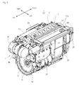
Fig. 1] Fig. 1 is a perspective rear view of an engine. - [
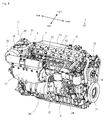
Fig. 2] Fig. 2 is a perspective front view of the engine. - [
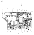
Fig. 3] Fig. 3 is a side view of the engine. - [
Fig. 4] Fig. 4 is a perspective view of a state in which a top cover is detached. - [
Fig. 5] Fig. 5 is a perspective view of the top cover. - [
Fig. 6] Fig. 6 is a sectional view of an engine side operation part. - [
Fig. 7] Fig. 7 is a perspective view of a state in which an operation device is connected to a maintenance connector. - [
Fig. 8] Fig. 8 is a plan view of the engine side operation part. - Firstly, an entire configuration of an
engine 1 according to the present invention is explained referring toFigs. 1 to 4 . In below explanation, a direction of a crankshaft of theengine 1 is regarded as a longitudinal direction, and a side of an output shaft of theengine 1 is regarded as a rear side. - The
engine 1 is arranged in an engine room formed in a bottom of a ship. In theengine 1, acylinder block 4 in which a plurality of pistons are housed longitudinally is provided, and acylinder head 5 is provided at an upper end of thecylinder block 4 and covers the upper end. Anoil pan 6 is provided at a lower end of thecylinder block 4 and pools lubricating oil. An upper surface of thecylinder head 5 is covered by a rockerarm chamber casing 7, and a rocker arm chamber (not shown) for housing a rocker arm, a fuel injection valve and the like is formed in the rockerarm chamber casing 7. - In the
cylinder block 4, acrankshaft 8 is provided substantially horizontally so as to be extended longitudinally. Aflywheel 9 is attached to a rear end of thecrankshaft 8. Theflywheel 9 is covered by aflywheel housing 10 fixed to a rear end of thecylinder block 4. - A
gear casing 3 is attached to a front surface of thecylinder block 4. A lubricating oil pump is housed in a left side of thegear casing 3. Aseawater pump 27 is attached to a rear surface of a right side of thegear casing 3. Afresh water pump 14 is attached to an upper left part of thegear casing 3. Analternator 15 is attached to an upper right part of thegear casing 3. Thefresh water pump 14 and thealternator 15 are driven by thecrankshaft 8 via pulleys and a belt, and the front surface is covered by abelt cover 16. - An
exhaust manifold 13 is provided for substantially the same length as thecylinder head 5 in a right side surface of thecylinder head 5 along the right side surface. Acontainer box 26 for various relays, a fuse and the like is provided at a right outer side of theexhaust manifold 13. Below theexhaust manifold 13, theseawater pump 27 which pumps up seawater as cooling water and afresh water cooler 28 which cools fresh water supplied to a cooling jacket of a main body of theengine 1 for cooling by heat exchange with the seawater are disposed in this order from the front side. - Behind the
cylinder head 5, asupercharger 2 is provided. A part of fresh water from thefresh water cooler 28 is supplied to thesupercharger 2, and acasing 39 which covers a turbine rotated by exhaust gas of thesupercharger 2 is cooled by the fresh water. - An
intake manifold 12 is provided for substantially the same length as thecylinder head 5 in a left side surface of thecylinder head 5 along the left side surface. A rear part of theintake manifold 12 is communicated with acompressor 18 of thesupercharger 2 via an intake passage. An intercooler 22 cooling intake air from thesupercharger 2 by heat exchange with seawater is arranged at a left side of the rear part of theintake manifold 12. - Above the
intake manifold 12, acommon rail 23 is disposed in parallel to theintake manifold 12. Thecommon rail 23 is connected to an injector (not shown) which injects fuel, sent pressingly from afuel pump 24, from thecommon rail 23 via a high pressure pipe to each combustion chamber. Thefuel pump 24 is disposed in a front part of a left side surface of thecylinder block 4 and afuel filter 25 is arranged above thefuel pump 24 so as to supply filtered fuel. Upper parts of thecommon rail 23 and theintake manifold 12 are covered by atop cover 11. -
Oil filters intercooler 22, and anoil cooler 29 is disposed below theintercooler 22. Acontrol unit 20 is arranged in a space between theoil filters intercooler 22 and theoil cooler 29 arranged at the rear side and arrayed vertically and thefuel filter 25 and thefuel pump 24 arranged at the front side and arrayed vertically, and a side surface of thecontrol unit 20 is covered by anelectric box 21. Thecontrol unit 20 has an ECU (engine control unit), a relay, a driver and the like. - In this configuration, high pressure fuel obtained by compression with the
fuel pump 24 is distributed via thecommon rail 23 to the injector arranged for each of the cylinders, and fuel injection amount, injection timing and the like are controlled suitably with thecontrol unit 20, whereby a common rail type electronic control fuel injection system is formed. - Cooling seawater for heat exchange is pumped up from a seawater inlet with the
seawater pump 27. The pumped seawater flows from theseawater pump 27 to thefresh water cooler 28, theintercooler 22 and theoil cooler 29 and is heat-exchanged respectively. - Next, the
top cover 11 and an engineside operation part 40 of the present invention are explained referring toFigs. 1 ,4 to 8 . - The
top cover 11 is configured plate-like and covers upper parts of thecontrol unit 20, thecommon rail 23 and theintake manifold 12. Thetop cover 11 is fixed to thecylinder head 5 and theintake manifold 12 with bolts or the like. Ablank part 11a is formed so as to penetrate vertically a left side of a front part of thetop cover 11. Theblank part 11a is arranged substantially above thecontrol unit 20. Namely, theblank part 11a is shifted toward thecontrol unit 20. Theblank part 11a is configured by an opening (hole) or a notch. In this embodiment, the opening is employed. A shape of the opening is not limited and the opening has enough size for operating the engineside operation part 40 discussed later. A lid may be provided to theblank part 11a so as to prevent intrusion of dust and the like. - The engine
side operation part 40 is arranged so as to face theblank part 11a. The engineside operation part 40 is arranged at a position above theintake manifold 12 at which temperature is not high, and arranged in a space near the upper part of thecontrol unit 20 and surrounded by theoil filter 31, thecommon rail 23, thefuel filter 25 and theintake manifold 12, and covered by thetop cover 11 and theelectric box 21. The engineside operation part 40 includes anemergency stop switch 41, amaintenance connector 42 and afuse box 46 of a control system. The engineside operation part 40 is not limited to theemergency stop switch 41, themaintenance connector 42 and thefuse box 46 of the control system, and an accelerator lever (control lever) and the like may be arranged. - The
emergency stop switch 41 is configured by a push button switch and connected to thecontrol unit 20 or the injector, whereby fuel supply is stopped by pushing theemergency stop switch 41 so as to stop theengine 1. Accordingly, at maintenance of theengine 1, or when a problem occurs in a ship operation part such as a cabin of the ship and emergency stop is required, theengine 1 can be stopped by operating theemergency stop switch 41 through theblank part 11a. - As shown in
Fig. 7 , themaintenance connector 42 is connected to thecontrol unit 20 via awire 43. An opening side of themaintenance connector 42 can be connected to a connector provided at one of ends of aconnection cable 44. The other end of theconnection cable 44 can be connected to anoperation device 45 which is a personal computer or the like. By connecting theoperation device 45 to thecontrol unit 20 via theconnection cable 44, themaintenance connector 42 and thewire 43, maintenance work such as reading of data stored in thecontrol unit 20 into theoperation device 45, rewriting of programs and set values of thecontrol unit 20, and operation of the injector, a valve, a motor and the like by manual operation of theoperation device 45 can be performed. - The
fuse box 46 of the control system houses a fuse provided between thecontrol unit 20 and a battery power source. An upper part of thefuse box 46 is covered by a lid so as to exchange the fuse from an upper side. - As shown in
Fig. 6 , each of upper ends of theemergency stop switch 41, themaintenance connector 42 and thefuse box 46 of the control system which constitute the engineside operation part 40 is positioned lower than upper surfaces the top cover and thefuse box 46 of the control system. Namely, theemergency stop switch 41, themaintenance connector 42 and the fuse box of the control system are not projected upward from thetop cover 11 while arranged in theblank part 11a so as not to be obstructive to an operator walking on thetop cover 11. - As the above, in the
top cover 11 provided on an upper surface of theengine 1 arranged in the engine room of the ship, theblank part 11a is formed so as to penetrate vertically thetop cover 11, the engineside operation part 40 is arranged so as to face theblank part 11a, and the upper end of the engineside operation part 40 is positioned lower than the upper surface of thetop cover 11, whereby an operator can access easily to the engineside operation part 40 from the upper side in the engine room. Namely, from above theblank part 11a, theemergency stop switch 41 can be operated easily, connection operation to themaintenance connector 42 can be performed easily, and the fuse housed in thefuse box 46 of the control system can be exchanged easily. Operation and maintenance of theengine 1 can be performed without detaching thetop cover 11. Since the engineside operation part 40 is lower than the upper surface of thetop cover 11, theemergency stop switch 41, themaintenance connector 42 and thefuse box 46 of the control system are protected with thetop cover 11 without being damaged by accidentally tramping and being stumbled thereon. - The
control unit 20 is arranged in a side surface of theengine 1, the engineside operation part 40 is connected to thecontrol unit 20, and when viewed in plan, theblank part 11a of thetop cover 11 in which the engineside operation part 40 is arranged is shifted toward thecontrol unit 20, whereby wiring between thecontrol unit 20 and the engineside operation part 40 can be shortened and management becomes easy. - The engine
side operation part 40 has theemergency stop switch 41, themaintenance connector 42 and thefuse box 46 of the control system, whereby necessary minimum parts of theemergency stop switch 41, themaintenance connector 42 and thefuse box 46 of the control system can be housed in the smallblank part 11 a. Accordingly, the engine can be stopped quickly with theemergency stop switch 41 without moving to the operation part and performing stop operation at the time of the maintenance, thecontrol unit 20 can be connected to theoperation device 45 without detaching thetop cover 11, and the fuse housed in thefuse box 46 of the control system can be exchanged easily. -
- 1
- engine
- 11
- top cover
- 11a
- blank part
- 20
- control unit
- 40
- engine side operation part
- 41
- emergency stop switch
- 42
- maintenance connector
- 46
- fuse box
Claims (3)
- An engine characterized in that
a top cover is provided on an upper surface of the engine arranged in an engine room of a ship,
a blank part is formed in the top cover so as to penetrate vertically the top cover,
an engine side operation part is arranged in the blank part so as to face the blank part, and an upper end of the engine side operation part is positioned lower than an upper surface of the top cover. - The engine according to claim 1,
wherein a control unit controlling the engine is arranged in a side surface of the engine, wherein the engine side operation part is connected to the control unit, and
wherein the blank part of the top cover in which the engine side operation part is arranged is shifted toward the control unit in top planar view. - The engine according to claim 1 or 2, wherein the engine side operation part has an emergency stop switch, a maintenance connector and a fuse box of a control system.
Applications Claiming Priority (1)
| Application Number | Priority Date | Filing Date | Title |
|---|---|---|---|
| JP2015066361A JP6387552B2 (en) | 2015-03-27 | 2015-03-27 | engine |
Publications (2)
| Publication Number | Publication Date |
|---|---|
| EP3075980A1 true EP3075980A1 (en) | 2016-10-05 |
| EP3075980B1 EP3075980B1 (en) | 2018-01-03 |
Family
ID=55661229
Family Applications (1)
| Application Number | Title | Priority Date | Filing Date |
|---|---|---|---|
| EP16161734.5A Active EP3075980B1 (en) | 2015-03-27 | 2016-03-22 | Engine |
Country Status (3)
| Country | Link |
|---|---|
| US (1) | US10087835B2 (en) |
| EP (1) | EP3075980B1 (en) |
| JP (1) | JP6387552B2 (en) |
Cited By (1)
| Publication number | Priority date | Publication date | Assignee | Title |
|---|---|---|---|---|
| EP4242449A1 (en) * | 2022-03-10 | 2023-09-13 | Yanmar Holdings Co., Ltd. | Engine |
Families Citing this family (7)
| Publication number | Priority date | Publication date | Assignee | Title |
|---|---|---|---|---|
| USD810144S1 (en) * | 2016-11-09 | 2018-02-13 | Holley Performance Products, Inc. | Engine valley cover |
| USD812102S1 (en) * | 2016-11-09 | 2018-03-06 | Holley Performance Products, Inc. | Engine valley cover |
| USD811440S1 (en) * | 2016-11-09 | 2018-02-27 | Holley Performance Products, Inc. | Engine valley cover |
| USD811439S1 (en) * | 2016-11-09 | 2018-02-27 | Holley Performance Products, Inc. | Engine valley cover |
| JP1591709S (en) * | 2017-03-02 | 2017-11-27 | ||
| JP1672373S (en) * | 2020-02-10 | 2020-11-09 | ||
| JP7813214B2 (en) * | 2022-11-17 | 2026-02-12 | 株式会社クボタ | Engine with electronics |
Citations (5)
| Publication number | Priority date | Publication date | Assignee | Title |
|---|---|---|---|---|
| EP0819839A1 (en) * | 1996-07-20 | 1998-01-21 | Daimler-Benz Aktiengesellschaft | Internal combustion engine with an acoustic insulating cover and a cooling air fan |
| US20110196552A1 (en) * | 2010-02-10 | 2011-08-11 | Pierre Garon | Control system and method for starting and stopping marine engines |
| JP2012097676A (en) * | 2010-11-02 | 2012-05-24 | Yanmar Co Ltd | V type engine |
| JP2013148046A (en) | 2012-01-20 | 2013-08-01 | Yanmar Co Ltd | Ship engine |
| EP2832981A1 (en) * | 2012-03-28 | 2015-02-04 | Yanmar Co., Ltd. | Engine |
Family Cites Families (11)
| Publication number | Priority date | Publication date | Assignee | Title |
|---|---|---|---|---|
| JPH0633752B2 (en) * | 1987-05-29 | 1994-05-02 | 株式会社クボタ | Engine cell start and stop device |
| JP2001287603A (en) * | 2000-04-06 | 2001-10-16 | Sumitomo Wiring Syst Ltd | Wire harness for automobile |
| JP2003072687A (en) * | 2001-09-06 | 2003-03-12 | Kawasaki Heavy Ind Ltd | Personal watercraft and engine |
| JP4563858B2 (en) * | 2005-04-12 | 2010-10-13 | 本田技研工業株式会社 | Outboard motor |
| US20110155888A1 (en) * | 2009-08-31 | 2011-06-30 | Justin Jordahl | Mobile power unit with pto |
| CN104114830B (en) * | 2012-01-20 | 2017-09-08 | 洋马株式会社 | Marine engine |
| WO2014150742A1 (en) * | 2013-03-15 | 2014-09-25 | Walbro Engine Management, L.L.C. | Ignition diagnostics system |
| DE102013208231A1 (en) * | 2013-05-06 | 2014-11-06 | Mahle International Gmbh | Cylinder head cover |
| JP2015024803A (en) * | 2013-12-12 | 2015-02-05 | ヤンマー株式会社 | Small ship |
| JP2015105038A (en) * | 2013-11-29 | 2015-06-08 | ヤマハ発動機株式会社 | Propulsion machine for ship |
| JP6237175B2 (en) * | 2013-12-05 | 2017-11-29 | 三菱自動車工業株式会社 | engine |
-
2015
- 2015-03-27 JP JP2015066361A patent/JP6387552B2/en active Active
-
2016
- 2016-03-22 EP EP16161734.5A patent/EP3075980B1/en active Active
- 2016-03-23 US US15/078,578 patent/US10087835B2/en not_active Expired - Fee Related
Patent Citations (5)
| Publication number | Priority date | Publication date | Assignee | Title |
|---|---|---|---|---|
| EP0819839A1 (en) * | 1996-07-20 | 1998-01-21 | Daimler-Benz Aktiengesellschaft | Internal combustion engine with an acoustic insulating cover and a cooling air fan |
| US20110196552A1 (en) * | 2010-02-10 | 2011-08-11 | Pierre Garon | Control system and method for starting and stopping marine engines |
| JP2012097676A (en) * | 2010-11-02 | 2012-05-24 | Yanmar Co Ltd | V type engine |
| JP2013148046A (en) | 2012-01-20 | 2013-08-01 | Yanmar Co Ltd | Ship engine |
| EP2832981A1 (en) * | 2012-03-28 | 2015-02-04 | Yanmar Co., Ltd. | Engine |
Cited By (2)
| Publication number | Priority date | Publication date | Assignee | Title |
|---|---|---|---|---|
| EP4242449A1 (en) * | 2022-03-10 | 2023-09-13 | Yanmar Holdings Co., Ltd. | Engine |
| EP4678908A3 (en) * | 2022-03-10 | 2026-02-11 | Yanmar Holdings Co., Ltd. | Engine |
Also Published As
| Publication number | Publication date |
|---|---|
| EP3075980B1 (en) | 2018-01-03 |
| US20160281600A1 (en) | 2016-09-29 |
| JP2016186243A (en) | 2016-10-27 |
| US10087835B2 (en) | 2018-10-02 |
| JP6387552B2 (en) | 2018-09-12 |
Similar Documents
| Publication | Publication Date | Title |
|---|---|---|
| EP3075980B1 (en) | Engine | |
| US10208705B2 (en) | Engine equipped with wire harness cover | |
| KR101155706B1 (en) | Vertical multi-cylinder diesel engine | |
| US9790848B2 (en) | Engine | |
| CN104114830A (en) | Ship engine | |
| CN104204488B (en) | Engine | |
| EP2798171A1 (en) | Reciprocating engine | |
| EP3726044B1 (en) | Cylinder head and engine | |
| JP6005379B2 (en) | engine | |
| EP4242449B1 (en) | Engine | |
| EP4390086A1 (en) | Engine | |
| DE202009005463U1 (en) | Modular energy conversion system with combustion engine of low power for use in combined heat and power plants, power generators, pumps or compressors | |
| JP2023131928A (en) | engine | |
| JP2021008834A (en) | engine | |
| JP2015121110A (en) | Marine engine | |
| JP2013204493A (en) | Engine |
Legal Events
| Date | Code | Title | Description |
|---|---|---|---|
| PUAI | Public reference made under article 153(3) epc to a published international application that has entered the european phase |
Free format text: ORIGINAL CODE: 0009012 |
|
| AK | Designated contracting states |
Kind code of ref document: A1 Designated state(s): AL AT BE BG CH CY CZ DE DK EE ES FI FR GB GR HR HU IE IS IT LI LT LU LV MC MK MT NL NO PL PT RO RS SE SI SK SM TR |
|
| AX | Request for extension of the european patent |
Extension state: BA ME |
|
| STAA | Information on the status of an ep patent application or granted ep patent |
Free format text: STATUS: REQUEST FOR EXAMINATION WAS MADE |
|
| 17P | Request for examination filed |
Effective date: 20170405 |
|
| RBV | Designated contracting states (corrected) |
Designated state(s): AL AT BE BG CH CY CZ DE DK EE ES FI FR GB GR HR HU IE IS IT LI LT LU LV MC MK MT NL NO PL PT RO RS SE SI SK SM TR |
|
| GRAP | Despatch of communication of intention to grant a patent |
Free format text: ORIGINAL CODE: EPIDOSNIGR1 |
|
| STAA | Information on the status of an ep patent application or granted ep patent |
Free format text: STATUS: GRANT OF PATENT IS INTENDED |
|
| INTG | Intention to grant announced |
Effective date: 20170808 |
|
| GRAS | Grant fee paid |
Free format text: ORIGINAL CODE: EPIDOSNIGR3 |
|
| GRAA | (expected) grant |
Free format text: ORIGINAL CODE: 0009210 |
|
| STAA | Information on the status of an ep patent application or granted ep patent |
Free format text: STATUS: THE PATENT HAS BEEN GRANTED |
|
| AK | Designated contracting states |
Kind code of ref document: B1 Designated state(s): AL AT BE BG CH CY CZ DE DK EE ES FI FR GB GR HR HU IE IS IT LI LT LU LV MC MK MT NL NO PL PT RO RS SE SI SK SM TR |
|
| REG | Reference to a national code |
Ref country code: GB Ref legal event code: FG4D |
|
| REG | Reference to a national code |
Ref country code: CH Ref legal event code: EP Ref country code: AT Ref legal event code: REF Ref document number: 960498 Country of ref document: AT Kind code of ref document: T Effective date: 20180115 |
|
| REG | Reference to a national code |
Ref country code: IE Ref legal event code: FG4D |
|
| REG | Reference to a national code |
Ref country code: DE Ref legal event code: R096 Ref document number: 602016001259 Country of ref document: DE |
|
| REG | Reference to a national code |
Ref country code: FR Ref legal event code: PLFP Year of fee payment: 3 |
|
| REG | Reference to a national code |
Ref country code: NL Ref legal event code: FP |
|
| REG | Reference to a national code |
Ref country code: LT Ref legal event code: MG4D |
|
| REG | Reference to a national code |
Ref country code: AT Ref legal event code: MK05 Ref document number: 960498 Country of ref document: AT Kind code of ref document: T Effective date: 20180103 |
|
| PG25 | Lapsed in a contracting state [announced via postgrant information from national office to epo] |
Ref country code: HR Free format text: LAPSE BECAUSE OF FAILURE TO SUBMIT A TRANSLATION OF THE DESCRIPTION OR TO PAY THE FEE WITHIN THE PRESCRIBED TIME-LIMIT Effective date: 20180103 Ref country code: CY Free format text: LAPSE BECAUSE OF FAILURE TO SUBMIT A TRANSLATION OF THE DESCRIPTION OR TO PAY THE FEE WITHIN THE PRESCRIBED TIME-LIMIT Effective date: 20180103 Ref country code: FI Free format text: LAPSE BECAUSE OF FAILURE TO SUBMIT A TRANSLATION OF THE DESCRIPTION OR TO PAY THE FEE WITHIN THE PRESCRIBED TIME-LIMIT Effective date: 20180103 Ref country code: NO Free format text: LAPSE BECAUSE OF FAILURE TO SUBMIT A TRANSLATION OF THE DESCRIPTION OR TO PAY THE FEE WITHIN THE PRESCRIBED TIME-LIMIT Effective date: 20180403 Ref country code: ES Free format text: LAPSE BECAUSE OF FAILURE TO SUBMIT A TRANSLATION OF THE DESCRIPTION OR TO PAY THE FEE WITHIN THE PRESCRIBED TIME-LIMIT Effective date: 20180103 Ref country code: LT Free format text: LAPSE BECAUSE OF FAILURE TO SUBMIT A TRANSLATION OF THE DESCRIPTION OR TO PAY THE FEE WITHIN THE PRESCRIBED TIME-LIMIT Effective date: 20180103 |
|
| PG25 | Lapsed in a contracting state [announced via postgrant information from national office to epo] |
Ref country code: LV Free format text: LAPSE BECAUSE OF FAILURE TO SUBMIT A TRANSLATION OF THE DESCRIPTION OR TO PAY THE FEE WITHIN THE PRESCRIBED TIME-LIMIT Effective date: 20180103 Ref country code: SE Free format text: LAPSE BECAUSE OF FAILURE TO SUBMIT A TRANSLATION OF THE DESCRIPTION OR TO PAY THE FEE WITHIN THE PRESCRIBED TIME-LIMIT Effective date: 20180103 Ref country code: AT Free format text: LAPSE BECAUSE OF FAILURE TO SUBMIT A TRANSLATION OF THE DESCRIPTION OR TO PAY THE FEE WITHIN THE PRESCRIBED TIME-LIMIT Effective date: 20180103 Ref country code: RS Free format text: LAPSE BECAUSE OF FAILURE TO SUBMIT A TRANSLATION OF THE DESCRIPTION OR TO PAY THE FEE WITHIN THE PRESCRIBED TIME-LIMIT Effective date: 20180103 Ref country code: BG Free format text: LAPSE BECAUSE OF FAILURE TO SUBMIT A TRANSLATION OF THE DESCRIPTION OR TO PAY THE FEE WITHIN THE PRESCRIBED TIME-LIMIT Effective date: 20180403 Ref country code: IS Free format text: LAPSE BECAUSE OF FAILURE TO SUBMIT A TRANSLATION OF THE DESCRIPTION OR TO PAY THE FEE WITHIN THE PRESCRIBED TIME-LIMIT Effective date: 20180503 Ref country code: GR Free format text: LAPSE BECAUSE OF FAILURE TO SUBMIT A TRANSLATION OF THE DESCRIPTION OR TO PAY THE FEE WITHIN THE PRESCRIBED TIME-LIMIT Effective date: 20180404 Ref country code: PL Free format text: LAPSE BECAUSE OF FAILURE TO SUBMIT A TRANSLATION OF THE DESCRIPTION OR TO PAY THE FEE WITHIN THE PRESCRIBED TIME-LIMIT Effective date: 20180103 |
|
| REG | Reference to a national code |
Ref country code: DE Ref legal event code: R097 Ref document number: 602016001259 Country of ref document: DE |
|
| PG25 | Lapsed in a contracting state [announced via postgrant information from national office to epo] |
Ref country code: AL Free format text: LAPSE BECAUSE OF FAILURE TO SUBMIT A TRANSLATION OF THE DESCRIPTION OR TO PAY THE FEE WITHIN THE PRESCRIBED TIME-LIMIT Effective date: 20180103 Ref country code: RO Free format text: LAPSE BECAUSE OF FAILURE TO SUBMIT A TRANSLATION OF THE DESCRIPTION OR TO PAY THE FEE WITHIN THE PRESCRIBED TIME-LIMIT Effective date: 20180103 Ref country code: EE Free format text: LAPSE BECAUSE OF FAILURE TO SUBMIT A TRANSLATION OF THE DESCRIPTION OR TO PAY THE FEE WITHIN THE PRESCRIBED TIME-LIMIT Effective date: 20180103 |
|
| PLBE | No opposition filed within time limit |
Free format text: ORIGINAL CODE: 0009261 |
|
| STAA | Information on the status of an ep patent application or granted ep patent |
Free format text: STATUS: NO OPPOSITION FILED WITHIN TIME LIMIT |
|
| PG25 | Lapsed in a contracting state [announced via postgrant information from national office to epo] |
Ref country code: SM Free format text: LAPSE BECAUSE OF FAILURE TO SUBMIT A TRANSLATION OF THE DESCRIPTION OR TO PAY THE FEE WITHIN THE PRESCRIBED TIME-LIMIT Effective date: 20180103 Ref country code: DK Free format text: LAPSE BECAUSE OF FAILURE TO SUBMIT A TRANSLATION OF THE DESCRIPTION OR TO PAY THE FEE WITHIN THE PRESCRIBED TIME-LIMIT Effective date: 20180103 Ref country code: SK Free format text: LAPSE BECAUSE OF FAILURE TO SUBMIT A TRANSLATION OF THE DESCRIPTION OR TO PAY THE FEE WITHIN THE PRESCRIBED TIME-LIMIT Effective date: 20180103 Ref country code: MC Free format text: LAPSE BECAUSE OF FAILURE TO SUBMIT A TRANSLATION OF THE DESCRIPTION OR TO PAY THE FEE WITHIN THE PRESCRIBED TIME-LIMIT Effective date: 20180103 Ref country code: CZ Free format text: LAPSE BECAUSE OF FAILURE TO SUBMIT A TRANSLATION OF THE DESCRIPTION OR TO PAY THE FEE WITHIN THE PRESCRIBED TIME-LIMIT Effective date: 20180103 |
|
| REG | Reference to a national code |
Ref country code: BE Ref legal event code: MM Effective date: 20180331 |
|
| 26N | No opposition filed |
Effective date: 20181005 |
|
| REG | Reference to a national code |
Ref country code: IE Ref legal event code: MM4A |
|
| PG25 | Lapsed in a contracting state [announced via postgrant information from national office to epo] |
Ref country code: LU Free format text: LAPSE BECAUSE OF NON-PAYMENT OF DUE FEES Effective date: 20180322 |
|
| PG25 | Lapsed in a contracting state [announced via postgrant information from national office to epo] |
Ref country code: IE Free format text: LAPSE BECAUSE OF NON-PAYMENT OF DUE FEES Effective date: 20180322 |
|
| PG25 | Lapsed in a contracting state [announced via postgrant information from national office to epo] |
Ref country code: SI Free format text: LAPSE BECAUSE OF FAILURE TO SUBMIT A TRANSLATION OF THE DESCRIPTION OR TO PAY THE FEE WITHIN THE PRESCRIBED TIME-LIMIT Effective date: 20180103 Ref country code: BE Free format text: LAPSE BECAUSE OF NON-PAYMENT OF DUE FEES Effective date: 20180331 |
|
| REG | Reference to a national code |
Ref country code: CH Ref legal event code: PL |
|
| PG25 | Lapsed in a contracting state [announced via postgrant information from national office to epo] |
Ref country code: LI Free format text: LAPSE BECAUSE OF NON-PAYMENT OF DUE FEES Effective date: 20190331 Ref country code: CH Free format text: LAPSE BECAUSE OF NON-PAYMENT OF DUE FEES Effective date: 20190331 Ref country code: MT Free format text: LAPSE BECAUSE OF NON-PAYMENT OF DUE FEES Effective date: 20180322 |
|
| PG25 | Lapsed in a contracting state [announced via postgrant information from national office to epo] |
Ref country code: TR Free format text: LAPSE BECAUSE OF FAILURE TO SUBMIT A TRANSLATION OF THE DESCRIPTION OR TO PAY THE FEE WITHIN THE PRESCRIBED TIME-LIMIT Effective date: 20180103 |
|
| PG25 | Lapsed in a contracting state [announced via postgrant information from national office to epo] |
Ref country code: PT Free format text: LAPSE BECAUSE OF FAILURE TO SUBMIT A TRANSLATION OF THE DESCRIPTION OR TO PAY THE FEE WITHIN THE PRESCRIBED TIME-LIMIT Effective date: 20180103 |
|
| PG25 | Lapsed in a contracting state [announced via postgrant information from national office to epo] |
Ref country code: MK Free format text: LAPSE BECAUSE OF NON-PAYMENT OF DUE FEES Effective date: 20180103 Ref country code: HU Free format text: LAPSE BECAUSE OF FAILURE TO SUBMIT A TRANSLATION OF THE DESCRIPTION OR TO PAY THE FEE WITHIN THE PRESCRIBED TIME-LIMIT; INVALID AB INITIO Effective date: 20160322 |
|
| REG | Reference to a national code |
Ref country code: DE Ref legal event code: R082 Ref document number: 602016001259 Country of ref document: DE Representative=s name: JOSTARNDT PATENTANWALTS-AG, DE Ref country code: DE Ref legal event code: R081 Ref document number: 602016001259 Country of ref document: DE Owner name: YANMAR POWER TECHNOLOGY CO., LTD., JP Free format text: FORMER OWNER: YANMAR CO., LTD., OSAKA, JP |
|
| REG | Reference to a national code |
Ref country code: NL Ref legal event code: HC Owner name: YANMAR POWER TECHNOLOGY CO, LTD.; JP Free format text: DETAILS ASSIGNMENT: CHANGE OF OWNER(S), CHANGE OF OWNER(S) NAME; FORMER OWNER NAME: YANMAR CO., LTD. Effective date: 20201126 |
|
| PGFP | Annual fee paid to national office [announced via postgrant information from national office to epo] |
Ref country code: GB Payment date: 20260324 Year of fee payment: 11 |
|
| PGFP | Annual fee paid to national office [announced via postgrant information from national office to epo] |
Ref country code: DE Payment date: 20260319 Year of fee payment: 11 |
|
| PGFP | Annual fee paid to national office [announced via postgrant information from national office to epo] |
Ref country code: IT Payment date: 20260324 Year of fee payment: 11 |
|
| PGFP | Annual fee paid to national office [announced via postgrant information from national office to epo] |
Ref country code: NL Payment date: 20260319 Year of fee payment: 11 |
|
| PGFP | Annual fee paid to national office [announced via postgrant information from national office to epo] |
Ref country code: FR Payment date: 20260320 Year of fee payment: 11 |