EP3075978A1 - Exhaust pipe structure - Google Patents
Exhaust pipe structure Download PDFInfo
- Publication number
- EP3075978A1 EP3075978A1 EP16162356.6A EP16162356A EP3075978A1 EP 3075978 A1 EP3075978 A1 EP 3075978A1 EP 16162356 A EP16162356 A EP 16162356A EP 3075978 A1 EP3075978 A1 EP 3075978A1
- Authority
- EP
- European Patent Office
- Prior art keywords
- exhaust pipe
- exhaust
- coupling member
- exhaust gas
- bottom plate
- Prior art date
- Legal status (The legal status is an assumption and is not a legal conclusion. Google has not performed a legal analysis and makes no representation as to the accuracy of the status listed.)
- Granted
Links
Images



Classifications
-
- F—MECHANICAL ENGINEERING; LIGHTING; HEATING; WEAPONS; BLASTING
- F01—MACHINES OR ENGINES IN GENERAL; ENGINE PLANTS IN GENERAL; STEAM ENGINES
- F01N—GAS-FLOW SILENCERS OR EXHAUST APPARATUS FOR MACHINES OR ENGINES IN GENERAL; GAS-FLOW SILENCERS OR EXHAUST APPARATUS FOR INTERNAL-COMBUSTION ENGINES
- F01N3/00—Exhaust or silencing apparatus having means for purifying, rendering innocuous, or otherwise treating exhaust
- F01N3/08—Exhaust or silencing apparatus having means for purifying, rendering innocuous, or otherwise treating exhaust for rendering innocuous
- F01N3/10—Exhaust or silencing apparatus having means for purifying, rendering innocuous, or otherwise treating exhaust for rendering innocuous by thermal or catalytic conversion of noxious components of exhaust
- F01N3/24—Exhaust or silencing apparatus having means for purifying, rendering innocuous, or otherwise treating exhaust for rendering innocuous by thermal or catalytic conversion of noxious components of exhaust characterised by constructional aspects of converting apparatus
- F01N3/28—Construction of catalytic reactors
-
- F—MECHANICAL ENGINEERING; LIGHTING; HEATING; WEAPONS; BLASTING
- F01—MACHINES OR ENGINES IN GENERAL; ENGINE PLANTS IN GENERAL; STEAM ENGINES
- F01N—GAS-FLOW SILENCERS OR EXHAUST APPARATUS FOR MACHINES OR ENGINES IN GENERAL; GAS-FLOW SILENCERS OR EXHAUST APPARATUS FOR INTERNAL-COMBUSTION ENGINES
- F01N13/00—Exhaust or silencing apparatus characterised by constructional features
- F01N13/009—Exhaust or silencing apparatus characterised by constructional features having two or more separate purifying devices arranged in series
-
- F—MECHANICAL ENGINEERING; LIGHTING; HEATING; WEAPONS; BLASTING
- F01—MACHINES OR ENGINES IN GENERAL; ENGINE PLANTS IN GENERAL; STEAM ENGINES
- F01N—GAS-FLOW SILENCERS OR EXHAUST APPARATUS FOR MACHINES OR ENGINES IN GENERAL; GAS-FLOW SILENCERS OR EXHAUST APPARATUS FOR INTERNAL-COMBUSTION ENGINES
- F01N13/00—Exhaust or silencing apparatus characterised by constructional features
- F01N13/08—Other arrangements or adaptations of exhaust conduits
-
- F—MECHANICAL ENGINEERING; LIGHTING; HEATING; WEAPONS; BLASTING
- F01—MACHINES OR ENGINES IN GENERAL; ENGINE PLANTS IN GENERAL; STEAM ENGINES
- F01N—GAS-FLOW SILENCERS OR EXHAUST APPARATUS FOR MACHINES OR ENGINES IN GENERAL; GAS-FLOW SILENCERS OR EXHAUST APPARATUS FOR INTERNAL-COMBUSTION ENGINES
- F01N13/00—Exhaust or silencing apparatus characterised by constructional features
- F01N13/18—Construction facilitating manufacture, assembly, or disassembly
- F01N13/1805—Fixing exhaust manifolds, exhaust pipes or pipe sections to each other, to engine or to vehicle body
-
- F—MECHANICAL ENGINEERING; LIGHTING; HEATING; WEAPONS; BLASTING
- F01—MACHINES OR ENGINES IN GENERAL; ENGINE PLANTS IN GENERAL; STEAM ENGINES
- F01N—GAS-FLOW SILENCERS OR EXHAUST APPARATUS FOR MACHINES OR ENGINES IN GENERAL; GAS-FLOW SILENCERS OR EXHAUST APPARATUS FOR INTERNAL-COMBUSTION ENGINES
- F01N13/00—Exhaust or silencing apparatus characterised by constructional features
- F01N13/18—Construction facilitating manufacture, assembly, or disassembly
- F01N13/1838—Construction facilitating manufacture, assembly, or disassembly characterised by the type of connection between parts of exhaust or silencing apparatus, e.g. between housing and tubes, between tubes and baffles
-
- F—MECHANICAL ENGINEERING; LIGHTING; HEATING; WEAPONS; BLASTING
- F01—MACHINES OR ENGINES IN GENERAL; ENGINE PLANTS IN GENERAL; STEAM ENGINES
- F01N—GAS-FLOW SILENCERS OR EXHAUST APPARATUS FOR MACHINES OR ENGINES IN GENERAL; GAS-FLOW SILENCERS OR EXHAUST APPARATUS FOR INTERNAL-COMBUSTION ENGINES
- F01N13/00—Exhaust or silencing apparatus characterised by constructional features
- F01N13/18—Construction facilitating manufacture, assembly, or disassembly
- F01N13/1861—Construction facilitating manufacture, assembly, or disassembly the assembly using parts formed by casting or moulding
-
- F—MECHANICAL ENGINEERING; LIGHTING; HEATING; WEAPONS; BLASTING
- F01—MACHINES OR ENGINES IN GENERAL; ENGINE PLANTS IN GENERAL; STEAM ENGINES
- F01N—GAS-FLOW SILENCERS OR EXHAUST APPARATUS FOR MACHINES OR ENGINES IN GENERAL; GAS-FLOW SILENCERS OR EXHAUST APPARATUS FOR INTERNAL-COMBUSTION ENGINES
- F01N13/00—Exhaust or silencing apparatus characterised by constructional features
- F01N13/18—Construction facilitating manufacture, assembly, or disassembly
- F01N13/1861—Construction facilitating manufacture, assembly, or disassembly the assembly using parts formed by casting or moulding
- F01N13/1866—Construction facilitating manufacture, assembly, or disassembly the assembly using parts formed by casting or moulding the channels or tubes thereof being made integrally with the housing
-
- F—MECHANICAL ENGINEERING; LIGHTING; HEATING; WEAPONS; BLASTING
- F01—MACHINES OR ENGINES IN GENERAL; ENGINE PLANTS IN GENERAL; STEAM ENGINES
- F01N—GAS-FLOW SILENCERS OR EXHAUST APPARATUS FOR MACHINES OR ENGINES IN GENERAL; GAS-FLOW SILENCERS OR EXHAUST APPARATUS FOR INTERNAL-COMBUSTION ENGINES
- F01N2260/00—Exhaust treating devices having provisions not otherwise provided for
- F01N2260/14—Exhaust treating devices having provisions not otherwise provided for for modifying or adapting flow area or back-pressure
-
- F—MECHANICAL ENGINEERING; LIGHTING; HEATING; WEAPONS; BLASTING
- F01—MACHINES OR ENGINES IN GENERAL; ENGINE PLANTS IN GENERAL; STEAM ENGINES
- F01N—GAS-FLOW SILENCERS OR EXHAUST APPARATUS FOR MACHINES OR ENGINES IN GENERAL; GAS-FLOW SILENCERS OR EXHAUST APPARATUS FOR INTERNAL-COMBUSTION ENGINES
- F01N2450/00—Methods or apparatus for fitting, inserting or repairing different elements
- F01N2450/20—Methods or apparatus for fitting, inserting or repairing different elements by mechanical joints, e.g. by deforming housing, tube, baffle plate or parts thereof
-
- F—MECHANICAL ENGINEERING; LIGHTING; HEATING; WEAPONS; BLASTING
- F01—MACHINES OR ENGINES IN GENERAL; ENGINE PLANTS IN GENERAL; STEAM ENGINES
- F01N—GAS-FLOW SILENCERS OR EXHAUST APPARATUS FOR MACHINES OR ENGINES IN GENERAL; GAS-FLOW SILENCERS OR EXHAUST APPARATUS FOR INTERNAL-COMBUSTION ENGINES
- F01N2470/00—Structure or shape of exhaust gas passages, pipes or tubes
-
- F—MECHANICAL ENGINEERING; LIGHTING; HEATING; WEAPONS; BLASTING
- F01—MACHINES OR ENGINES IN GENERAL; ENGINE PLANTS IN GENERAL; STEAM ENGINES
- F01N—GAS-FLOW SILENCERS OR EXHAUST APPARATUS FOR MACHINES OR ENGINES IN GENERAL; GAS-FLOW SILENCERS OR EXHAUST APPARATUS FOR INTERNAL-COMBUSTION ENGINES
- F01N2470/00—Structure or shape of exhaust gas passages, pipes or tubes
- F01N2470/18—Structure or shape of exhaust gas passages, pipes or tubes the axis of inlet or outlet tubes being other than the longitudinal axis of apparatus
Definitions
- the disclosure relates to an exhaust pipe structure that constitutes an exhaust system of an internal combustion engine.
- FIG. 4 of Japanese Patent Application Publication No. 2013-185529 illustrates a configuration in which a first exhaust pipe (referred to as “first casing” in JP 2013-185529 A ) extending along a first direction and a second exhaust pipe (referred to as “second casing” in JP 2013-185529 A ) disposed downstream of the first exhaust pipe in an exhaust gas flow direction and extending along a second direction perpendicular to the first direction are coupled together via a coupling member (referred to as "communication passage” in JP 2013-185529 A ).
- a diesel particulate filter (DPF) and a selective reduction catalyst are disposed inside these exhaust pipes.
- DPF diesel particulate filter
- a configuration as schematically illustrated in FIG. 9 may be employed.
- a first exhaust pipe 100 and a second exhaust pipe 200 are coupled together such that an upstream end portion of the second exhaust pipe 200 is inserted into a downstream end portion of the first exhaust pipe 100, that is, such that the first exhaust pipe 100 and the second exhaust pipe 200 overlap each other as viewed from a direction in which the first exhaust pipe 100 extends.
- the exhaust system can be made more compact by an amount corresponding to the insertion dimension (dimension "t" in FIG. 9 ).
- the dimension of the exhaust system in the vehicle-width direction can be decreased.
- a NOx storage reduction (NSR) catalyst 101 is disposed inside the first exhaust pipe 100
- a diesel particulate filter (DPF) 201 is disposed inside the second exhaust pipe 200.
- the exhaust gas flow passage area at a coupling site where the first exhaust pipe 100 and the second exhaust pipe 200 are coupled together is decreased by an amount corresponding to the insertion dimension. Therefore, simply employing the configuration in which the first and second exhaust pipes 100, 200 are coupled together such that the upstream end portion of the second exhaust pipe 200 is inserted into the downstream end portion of the first exhaust pipe 100 may lower the exhaust gas discharging performance at the coupling site, thereby causing an increase in pressure inside the exhaust pipe.
- the disclosure provides an exhaust pipe structure in which exhaust pipes extending in different directions are coupled together, the exhaust pipe structure making it possible to inhibit an increase in pressure of the exhaust gas at a coupling site where the exhaust pipes are coupled together.
- An example of the disclosure relates to an exhaust pipe structure including a first exhaust pipe extending along a first direction, a second exhaust pipe disposed downstream of the first exhaust pipe in an exhaust gas flow direction and extending along a second direction, the second direction intersecting the first direction, and a coupling member configured to couple the first exhaust pipe and the second exhaust pipe together such that the first exhaust pipe and the second exhaust pipe overlap each other as viewed from the first direction.
- the coupling member has an opening, the inside of the first exhaust pipe communicates with the inside of the second exhaust pipe via the opening.
- the coupling member includes a bottom plate portion, the bottom plate portion shaped so as to correspond to a region where the first exhaust pipe and the second exhaust pipe overlap each other as viewed from the first direction and that is adjacent to the opening as viewed from the first direction.
- the coupling member has a groove defined in a surface of the bottom plate portion. The surface of the bottom plate portion faces the inside of the first exhaust pipe. The groove extends along an outer edge portion of the bottom plate portion toward the opening.
- a first exhaust gas control apparatus may be disposed inside the first exhaust pipe, and a second exhaust gas control apparatus may be disposed inside the second exhaust pipe, in the region where the first exhaust pipe and the second exhaust pipe overlap each other as viewed from the first direction.
- the coupling member may be molded by lost-wax casting of stainless steel.
- the first exhaust pipe and the second exhaust pipe extending in different directions are coupled together via the coupling member so as to overlap each other, and the groove that guides the flow of exhaust gas is defined in the bottom plate portion of the coupling member.
- FIG. 1 is a view of an exhaust system including maniverters (closed coupled converters) and their vicinity as viewed from the rear side of a vehicle.
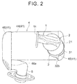
- FIG. 2 is a view of the exhaust system as viewed from the direction of an arrow II in FIG. 1 (as viewed from above).
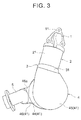
- FIG. 3 is a view of the exhaust system as viewed from the direction of an arrow III in FIG. 1 (as viewed from the right side of the vehicle).
- a manifold connection pipe 1 As illustrated in these drawings, in the exhaust system, a manifold connection pipe 1, a first maniverter 2, a coupling member 3, and a second maniverter 4 are arranged in this order from the upstream side toward the downstream side in an exhaust gas flow direction.
- the manifold connection pipe 1 is a stainless-steel pipe that couples together an exhaust manifold (not illustrated) and the first maniverter 2.
- An upstream portion of the manifold connection pipe 1 in the exhaust gas flow direction extends in a substantially horizontal direction (vehicle-width direction), whereas a downstream portion of the manifold connection pipe 1 in the exhaust gas flow direction is bent so as to extend in a substantially vertical direction (more specifically, in a direction inclined with respect to the vertical direction at a prescribed inclination angle (e.g., approximately 15°)).
- An upstream end portion of the manifold connection pipe 1 in the exhaust gas flow direction is provided with a flange 11.
- the flange 11 is connected to the exhaust manifold (not illustrated).
- the flange 11 is connected to a turbine housing of the turbocharger (not illustrated).
- the first maniverter 2 includes a generally cylindrical first exhaust pipe 21 and a NOx storage reduction (NSR) catalyst 22 (see dashed lines in FIG. 1 ) housed inside the first exhaust pipe 21.
- NSR NOx storage reduction
- the first exhaust pipe 21 is made of stainless steel, and extends along the direction in which the downstream portion of the manifold connection pipe 1 in the exhaust gas flow direction extends.
- the direction in which the first exhaust pipe 21 extends (the direction along a center line O1 of the first exhaust pipe 21 (see FIG. 1 )) is an example of "first direction”.
- the outer diameter of an upstream end portion of the first exhaust pipe 21 in the exhaust gas flow direction is substantially equal to the inner diameter of a downstream end portion of the manifold connection pipe 1 in the exhaust gas flow direction.
- the upstream end portion of the first exhaust pipe 21 in the exhaust gas flow direction is inserted into the downstream end portion of the manifold connection pipe 1 in the exhaust gas flow direction.
- the manifold connection pipe 1 and the first exhaust pipe 21 are joined together, for example, by welding.
- Multiple brackets (not illustrated) for securing the first maniverter 2 to, for example, a body of the vehicle are attached respectively to multiple positions on the outer peripheral surface of the first exhaust pipe 21.
- the NSR catalyst 22 (an example of “first exhaust gas control apparatus") stores NOx in the exhaust gas flowing into the first maniverter 2 when the oxygen concentration in the exhaust gas is high, whereas the NSR catalyst 22reduces the stored NOx when the oxygen concentration in the exhaust gas flowing into the first maniverter 2 is decreased and there is a reducing agent. Thus, HC, CO, and NOx in the exhaust gas are removed.
- the second maniverter 4 includes an exhaust pipe unit 41, and a NOx storage reduction (NSR) catalyst 42 and a diesel particulate filter (DPF) 43 (see dashed lines in FIG. 1 ) that are housed inside the exhaust pipe unit 41.
- NSR NOx storage reduction
- DPF diesel particulate filter
- the exhaust pipe unit 41 includes a second exhaust pipe 44, a first side cover 45, and a second side cover 46, all of which are made of stainless steel.
- the second exhaust pipe 44 is a cylindrical pipe that extends in a substantially horizontal direction (vehicle-width direction).
- the direction (substantially horizontal direction) in which the second exhaust pipe 44 extends is an example of "second direction”. In other words, the second exhaust pipe 44 extends along the second direction that intersects the first direction.
- the outer diameter of the second exhaust pipe 44 is set larger than the outer diameter of the first exhaust pipe 21 of the first maniverter 2.
- the NSR catalyst (an example of "second exhaust gas control apparatus") 42 housed inside the second exhaust pipe 44, is disposed upstream of the DPF 43 in the exhaust gas flow direction.
- the DPF 43 is also housed inside the second exhaust pipe 44.
- the NSR catalyst 42 housed inside the second exhaust pipe 44 is larger than the NSR catalyst 22 included in the first maniverter 2.
- the function of the NSR catalyst 42 is the same as that of the NSR catalyst 22 included in the first maniverter 2.
- the DPF 43 is, for example, a porous ceramic structural body, and traps particulate matter (PM) contained in the exhaust gas when the exhaust gas passes through a porous wall.
- the second exhaust pipe 44 has a feature that an upstream end portion of the second exhaust pipe 44 in the exhaust gas flow direction overlaps the first exhaust pipe 21. That is, as viewed from the direction in which the first exhaust pipe 21 extends (as viewed from the first direction), the first exhaust pipe 21 and the upstream end portion of the second exhaust pipe 44 in the exhaust gas flow direction overlap each other. More specifically, the first and second exhaust pipes 21, 44 overlap each other (overlap each other as viewed from the first direction) such that the center line O1 of the first exhaust pipe 21 intersects the outer peripheral surface of the second exhaust pipe 44.
- the NSR catalyst 42 is housed inside the second exhaust pipe 44, at the upstream end portion of the second exhaust pipe 44 in the exhaust gas flow direction.
- the center line O1 of the first exhaust pipe 21 intersects also the outer peripheral surface of the NSR catalyst 42. That is, a part of the NSR catalyst 42 is disposed inside the second exhaust pipe 44, in a region where the first exhaust pipe 21 and the second exhaust pipe 44 overlap each other as viewed from the first direction.
- Brackets for securing the second maniverter 4 to, for example, the body of the vehicle are attached respectively to multiple positions on the outer peripheral surface the second exhaust pipe 44.
- the first side cover 45 is disposed across the coupling member 3 (described later) and the second exhaust pipe 44, and defines an exhaust gas flow space between the coupling member 3 and the second exhaust pipe 44.
- the joint structure of the first side cover 45, the coupling member 3, and the second exhaust pipe 44 will be described later.
- the second side cover 46 covers an opening at a downstream end portion of the second exhaust pipe 44 in the exhaust gas flow direction.
- the second side cover 46 includes an exhaust pipe connection portion 46a (see FIG. 2 and FIG. 3 ), and a downstream-side exhaust pipe 5 is connected to the exhaust pipe connection portion 46a.
- the downstream-side exhaust pipe 5 extends from the exhaust pipe connection portion 46a along the vehicle-width direction (extends rightward in FIG. 1 ), and is then bent toward the rear side of the vehicle.
- the coupling member 3 is a stainless-steel member that couples together the first exhaust pipe 21 of the first maniverter 2 and the exhaust pipe unit 41 of the second maniverter 4.
- the coupling member 3 is molded by lost-wax casting of stainless steel.
- lost-wax casting An example of lost-wax casting will be described below.
- wax is poured into a die to create a wax model
- a coating is applied to the model, and the model is dried sufficiently to produce a mold.
- the mold is heated to cause the wax inside the coating to melt and flow out, so that a cavity is created.
- the mold is finished by being baked and solidified in a kiln.
- molten metal is injected into the finished mold, and the mold is cooled to produce a cast product (the coupling member 3).
- FIG. 4 is a front view of the coupling member 3 (as viewed from the rear side of the vehicle as in the case of FIG. 1 ).
- FIG. 5 is a plan view of the coupling member 3 (as viewed from the first direction).
- FIG. 7 is a sectional view taken along the line VII-VII in FIG. 5 .
- FIG. 8 is a sectional view illustrating a site where the first and second exhaust pipes 21, 44 are coupled together via the coupling member 3.
- the coupling member 3 includes a first exhaust pipe joint portion 31, a vertical wall portion 32, and a bottom plate portion 33.
- the first exhaust pipe joint portion 31 is a generally cylindrical portion that is relatively short in the height direction.
- the inner diameter of the first exhaust pipe joint portion 31 is substantially equal to the outer diameter of a downstream end portion of the first exhaust pipe 21 in the exhaust gas flow direction.
- the downstream end portion of the first exhaust pipe 21 in the exhaust gas flow direction is inserted into the first exhaust pipe joint portion 31.
- the first exhaust pipe 21 and the coupling member 3 are joined together, for example, by welding.
- the vertical wall portion 32 is contiguous with the lower side of the first exhaust pipe joint portion 31.
- the vertical wall portion 32 includes a front vertical wall portion 32a (see FIG. 5 ) and a rear vertical wall portion 32b (see FIG. 1 and FIG. 5 ) disposed rearward of the front vertical wall portion 32a in the vehicle front-rear direction.
- the inner surfaces of the front vertical wall portion 32a and rear vertical wall portion 32b are shaped so as to conform to the outer peripheral surface of the second exhaust pipe 44.
- the inner surfaces 32e of the front vertical wall portion 32a and rear vertical wall portion 32b are overlapped with (placed on) the outer peripheral surface of the second exhaust pipe 44.
- the coupling member 3 (the vertical wall portions 32a, 32b of the coupling member 3) and the second exhaust pipe 44 are joined together, for example, by welding.
- the coupling member 3 have no vertical wall portion 32 on its right side in the vehicle-width direction. That is, a portion below a lower edge (lower edge 31a in FIG. 4 ) of a right side portion of the first exhaust pipe joint portion 31 in the vehicle-width direction is open toward the right side of the vehicle.
- the portion below the lower edge 31a is an opening 34 that is open toward the right side of the vehicle.
- the opening 34 is used as a space through which the exhaust gas that has flowed into the coupling member 3 flows toward the second maniverter 4. In other words, the opening 34 provides communication between the inside of the first exhaust pipe 21 and the inside of the second exhaust pipe 44.
- edge portions of the front vertical wall portion 32a and rear vertical wall portion 32b, the edge portions being closer to the opening 34, are used as joint portions 32c, 32d each having a generally flat outer surface to which the first side cover 45 of the second maniverter 4 is joined.
- the bottom plate portion 33 is disposed in the internal space of the first exhaust pipe joint portion 31, and is made of a plate material shaped so as to conform to the outer peripheral surface of the upstream end portion of the second exhaust pipe 44 (indicated by imaginary lines in FIG. 5 ) in the exhaust gas flow direction.
- the bottom plate portion 33 is made of a plate material shaped so as to correspond to a region that is adjacent to the opening 34 and where the first exhaust pipe 21 and the second exhaust pipe 44 overlap each other as viewed from the first direction.
- the bottom plate portion 33 is shaped so as to have an edge 33a facing the opening 34 and a generally arc-shaped outer edge 33b connected to the inner surface of the first exhaust pipe joint portion 31.
- the region where the first exhaust pipe 21 and the second exhaust pipe 44 overlap each other is a region indicated by the dashed oblique lines in FIG. 6 (view illustrating the first exhaust pipe 21 and the second exhaust pipe 44 as viewed from the first direction, and indicating the coupling member 3 by imaginary lines).
- the bottom plate portion 33 has a shape that generally coincides with the shape of this region.
- the first side cover 45 is joined to both the second exhaust pipe 44 and the coupling member 3. Specifically, the first side cover 45 covers the opening 34 of the coupling member 3 and an opening of the upstream end portion of the second exhaust pipe 44 in the exhaust gas flow direction.
- the first side cover 45 has an outer edge portion overlapped with the first exhaust pipe joint portion 31 and vertical wall portions 32a, 32b (joint portions 32c, 32d of the vertical wall portions 32a, 32b) of the coupling member 3 and an opening edge portion of the upstream end portion of the second exhaust pipe 44 in the exhaust gas flow direction.
- the first side cover 45 is joined to the coupling member 3 and the second exhaust pipe 44, for example, by welding.
- the internal space of the coupling member 3 and the internal space of the second exhaust pipe 44 communicate with each other through the space defined between the opening 34 of the coupling member 3 and the first side cover 45.
- the coupling member 3 has a feature that the bottom plate portion 33 of the coupling member 3 has a groove 35 that extends along the outer edge portion (the outer edge 33b) of the bottom plate portion 33 toward the opening 34.
- the outer edge portion of the bottom plate portion 33 that is, the region of the bottom plate portion 33 extending along the generally arc-shaped outer edge 33b connected to the inner surface of the first exhaust pipe joint portion 31, is depressed downward with respect to the other region of the bottom plate portion 33, and the depressed portion serves as the groove 35. That is, the sectional shape of the groove 35 at a position of the section illustrated in FIG. 7 continues to the opening 34 along the upper surface (surface facing the inside of the first exhaust pipe 21) of the bottom plate portion 33 (see FIG. 5 ).
- the groove 35 is formed in the bottom plate portion 33 in the above-described manner, a part of the exhaust gas that has flowed from the first exhaust pipe 21 of the first maniverter 2 into the coupling member 3 flows along the groove 35 (the flow of the exhaust gas is guided through the groove 35), and flows from the open ends (the portion facing the opening 34) of the groove 35 through the opening 34 into the second maniverter 4.
- the exhaust pipe structure according to the present embodiment is configured as described above.
- the exhaust gas discharged from the engine flows into the first maniverter 2 through the exhaust manifold and the manifold connection pipe 1.
- the exhaust gas that has flowed into the first maniverter 2 is cleaned up by the NSR catalyst 22 and then flows into the coupling member 3.
- a part of the exhaust gas that has flowed into the coupling member 3 flows inside the coupling member 3, in a relatively right side region in the vehicle-width direction.
- the exhaust gas flowing in the relatively right side region flows along the center line O1 of the first exhaust pipe 21 (along the first direction), and flows inside the coupling member 3 toward the opening 34.
- the exhaust gas flowing in the relatively right side region passes directly through the opening 34 and flows toward the second maniverter 4, as indicated by an arrow A in FIG. 7 and FIG. 8 .
- this exhaust gas passes through the opening 34 after flowing downward inside the coupling member 3, and then the flow direction thereof is changed to the horizontal direction (the direction toward the left side of the vehicle) along the shape of the inner surface of the first side cover 45, so that a flow of exhaust gas toward the NSR catalyst 42 and the DPF 43 is formed.
- the exhaust gas flowing toward the bottom plate portion 33 flows into the groove 35 along the bottom plate portion 33, as indicated by an arrow B in FIG. 5 and FIG. 8 .
- the groove 35 extends along the outer edge portion of the bottom plate portion 33. That is, the groove 35 has an arc-shape extending toward the opening 34.
- the exhaust gas flowing along the groove 35 forms arc-shaped flows around the center line of the first exhaust pipe joint portion 31 of the coupling member 3, as indicated by an arrow C and an arrow D in FIG. 5 .
- this exhaust gas flows into the opening 34 from the open ends (the portions facing the opening 34) of the groove 35, and forms arc-shaped flows (forms arc-shaped flows as viewed from the first direction as illustrated in FIG. 5 ) that enter the second maniverter 4.
- the exhaust gas that has flowed through a front side portion of the groove 35 in the vehicle front-rear direction passes through the opening 34 from the open end (the portion facing the opening 34) of the groove 35, and then flows into the second exhaust pipe 44 along a rear side portion of the inner surface (a portion of the inner surface on the rear side in the vehicle front-rear direction) of the second exhaust pipe 44 (flows into the second exhaust pipe 44 by coming around to the lower side of the bottom plate portion 33, as indicated by a dashed part of the arrow E in FIG. 5 and the arrow E in FIG. 7 and FIG. 8 ).
- the exhaust gas that has flowed through a rear side portion of the groove 35 in the vehicle front-rear direction passes through the opening 34 from the open end (the portion facing the opening 34) of the groove 35, and then flows into the second exhaust pipe 44 along a front side portion of the inner surface (a portion of the inner surface on the front side in the vehicle front-rear direction) of the second exhaust pipe 44 (flows into the second exhaust pipe 44 by coming around to the lower side of the bottom plate portion 33, as indicated by a dashed part of the arrow F in FIG. 5 ).
- the exhaust gas flows smoothly from the opening 34 into the second maniverter 4, and therefore favorable exhaust gas discharging performance is secured. As a result, it is possible to inhibit an increase in pressure of the exhaust gas at the coupling site where the first exhaust pipe 21 and the second exhaust pipe 44 are coupled together.
- the exhaust gas that has flowed into the second maniverter 4 is cleaned up by the NSR catalyst 42 and the particulate matter in the exhaust gas is trapped by the DPF 43. After that, the exhaust gas is released into the atmosphere.
- the exhaust system it is possible to make the exhaust system more compact by coupling together the first and second exhaust pipes 21, 44 such that the first and second exhaust pipes 21, 44 overlap each other, and it is also possible to allow the exhaust gas to smoothly flow from the opening 34 into the second maniverter 4 by causing the exhaust gas to flow along the groove 35 defined in the bottom plate portion 33 of the coupling member 3.
- favorable exhaust gas discharging performance is secured, which makes it possible to inhibit an increase in pressure of the exhaust gas at the coupling site where the first exhaust pipe 21 and the second exhaust pipe 44 are coupled together. As a result, the engine performance is sufficiently delivered.
- the exhaust gas flowing from the coupling member 3 into the second maniverter 4 forms arc-shaped flows, so that the exhaust gas mixing performance is improved and unevenness in each of the flow velocity and temperature of the exhaust gas is reduced. This also makes it possible to secure favorable exhaust gas discharging performance.
- the NSR catalyst 42 is disposed inside the second exhaust pipe 44, in the region where the first exhaust pipe 21 and the second exhaust pipe 44 overlap each other as viewed from the first direction.
- the overlapping site is an installation space for the NSR catalyst 42, as well as to improve the exhaust gas clean-up performance by providing the two NSR catalysts 22, 42.
- the coupling member 3 according to the present embodiment is molded by lost-wax casting of stainless steel. This makes it possible to enhance the flexibility of the shape of the coupling member 3 and to improve the corrosion resistance of the coupling member 3.
- the coupling member 3 is molded by lost-wax casting of stainless steel.
- the material and the production method of the coupling member 3 are not limited to those in the above-described embodiment, and any appropriate materials and production methods may be employed.
- the disclosure is applied to the exhaust system of the diesel engine mounted in the vehicle.
- the disclosure may be applied to exhaust systems of engines mounted in machines other than vehicles.
- the disclosure may be applied to exhaust systems of gasoline engines instead of exhaust systems of diesel engines.
- the exhaust gas control apparatuses to be housed in the maniverters 2, 4 are not limited to those in the above-described embodiment.
- a selective reduction catalyst (SCR catalyst) SCR catalyst
- a three way catalyst may be used.
Landscapes
- Engineering & Computer Science (AREA)
- Chemical & Material Sciences (AREA)
- Combustion & Propulsion (AREA)
- Mechanical Engineering (AREA)
- General Engineering & Computer Science (AREA)
- Chemical Kinetics & Catalysis (AREA)
- Health & Medical Sciences (AREA)
- Toxicology (AREA)
- Exhaust Silencers (AREA)
- Exhaust Gas After Treatment (AREA)
Abstract
Description
- The disclosure relates to an exhaust pipe structure that constitutes an exhaust system of an internal combustion engine.
- A known configuration in which exhaust pipes extending in different directions are coupled together has been employed to make an exhaust system more compact.
-
FIG. 4 of Japanese Patent Application Publication No.2013-185529 JP 2013-185529 A JP 2013-185529 A JP 2013-185529 A JP 2013-185529 A - To make an exhaust system more compact, a configuration as schematically illustrated in
FIG. 9 may be employed. In the configuration inFIG. 9 , afirst exhaust pipe 100 and asecond exhaust pipe 200 are coupled together such that an upstream end portion of thesecond exhaust pipe 200 is inserted into a downstream end portion of thefirst exhaust pipe 100, that is, such that thefirst exhaust pipe 100 and thesecond exhaust pipe 200 overlap each other as viewed from a direction in which thefirst exhaust pipe 100 extends. Thus, the exhaust system can be made more compact by an amount corresponding to the insertion dimension (dimension "t" inFIG. 9 ). For example, when the right-left direction inFIG. 9 coincides with the vehicle-width direction, the dimension of the exhaust system in the vehicle-width direction can be decreased. In the configuration illustrated inFIG. 9 , a NOx storage reduction (NSR)catalyst 101 is disposed inside thefirst exhaust pipe 100, and a diesel particulate filter (DPF) 201 is disposed inside thesecond exhaust pipe 200. - In this case, however, the exhaust gas flow passage area at a coupling site where the
first exhaust pipe 100 and thesecond exhaust pipe 200 are coupled together (the exhaust gas flow passage area at a site "s" inFIG. 9 ) is decreased by an amount corresponding to the insertion dimension. Therefore, simply employing the configuration in which the first andsecond exhaust pipes second exhaust pipe 200 is inserted into the downstream end portion of thefirst exhaust pipe 100 may lower the exhaust gas discharging performance at the coupling site, thereby causing an increase in pressure inside the exhaust pipe. - The disclosure provides an exhaust pipe structure in which exhaust pipes extending in different directions are coupled together, the exhaust pipe structure making it possible to inhibit an increase in pressure of the exhaust gas at a coupling site where the exhaust pipes are coupled together.
- An example of the disclosure relates to an exhaust pipe structure including a first exhaust pipe extending along a first direction, a second exhaust pipe disposed downstream of the first exhaust pipe in an exhaust gas flow direction and extending along a second direction, the second direction intersecting the first direction, and a coupling member configured to couple the first exhaust pipe and the second exhaust pipe together such that the first exhaust pipe and the second exhaust pipe overlap each other as viewed from the first direction. The coupling member has an opening, the inside of the first exhaust pipe communicates with the inside of the second exhaust pipe via the opening. The coupling member includes a bottom plate portion, the bottom plate portion shaped so as to correspond to a region where the first exhaust pipe and the second exhaust pipe overlap each other as viewed from the first direction and that is adjacent to the opening as viewed from the first direction. The coupling member has a groove defined in a surface of the bottom plate portion. The surface of the bottom plate portion faces the inside of the first exhaust pipe. The groove extends along an outer edge portion of the bottom plate portion toward the opening.
- With this configuration, a part of the exhaust gas that has flowed from the first exhaust pipe into the coupling member flows along the groove defined in the bottom plate portion of the coupling member, and flows from the groove through the opening into the second exhaust pipe. In other words, the flow of exhaust gas is guided by the groove. Thus, even when the first exhaust pipe and the second exhaust pipe are coupled together so as to overlap each other, it is possible to secure favorable exhaust gas discharging performance at the coupling site and to suppress an increase in pressure of the exhaust gas at the coupling site.
- In the above exhaust pipe structure, a first exhaust gas control apparatus may be disposed inside the first exhaust pipe, and a second exhaust gas control apparatus may be disposed inside the second exhaust pipe, in the region where the first exhaust pipe and the second exhaust pipe overlap each other as viewed from the first direction.
- Thus, it is possible to effectively use the inside of the second exhaust pipe, in the region where the first exhaust pipe and the second exhaust pipe overlap each other as viewed from the first direction, as the installation space for the second exhaust gas control apparatuses, as well as to improve the exhaust gas clean-up performance by installing the two exhaust gas control apparatuses.
- In the above exhaust pipe structure, the coupling member may be molded by lost-wax casting of stainless steel.
- Thus, it is possible to enhance the flexibility of the shape of the coupling member and to improve the corrosion resistance of the coupling member.
- In the above configuration, the first exhaust pipe and the second exhaust pipe extending in different directions are coupled together via the coupling member so as to overlap each other, and the groove that guides the flow of exhaust gas is defined in the bottom plate portion of the coupling member. Thus, it is possible to make the exhaust system more compact and to inhibit an increase in pressure of the exhaust gas at the coupling site.
- Features, advantages, and technical and industrial significance of disclosed embodiments will be described below with reference to the accompanying drawings, in which like numerals denote like elements, and wherein:
-
FIG. 1 is a view of an exhaust system including maniverters and their vicinity as viewed from the rear side of a vehicle; -
FIG. 2 is a view of the exhaust system as viewed from the direction of an arrow II inFIG. 1 ; -
FIG. 3 is a view of the exhaust system as viewed from the direction of an arrow III inFIG. 1 ; -
FIG. 4 is a front view of a coupling member; -
FIG. 5 is a plan view of the coupling member; -
FIG. 6 is a view illustrating a region where a first exhaust pipe and a second exhaust pipe overlap each other; -
FIG. 7 is a sectional view taken along the line VII-VII inFIG. 5 ; -
FIG. 8 is a sectional view of a site where the exhaust pipes are coupled together via the coupling member; and -
FIG. 9 is a sectional view schematically illustrating the configuration in which an upstream end portion of a second exhaust pipe is inserted into a downstream end portion of a first exhaust pipe. - Hereinafter, a disclosed embodiment will be described with reference to the accompanying drawings. In the embodiment described below, the disclosure is applied to an exhaust system of a diesel engine (internal combustion engine) mounted in a vehicle.
-
FIG. 1 is a view of an exhaust system including maniverters (closed coupled converters) and their vicinity as viewed from the rear side of a vehicle.FIG. 2 is a view of the exhaust system as viewed from the direction of an arrow II inFIG. 1 (as viewed from above).FIG. 3 is a view of the exhaust system as viewed from the direction of an arrow III inFIG. 1 (as viewed from the right side of the vehicle). - As illustrated in these drawings, in the exhaust system, a
manifold connection pipe 1, afirst maniverter 2, acoupling member 3, and asecond maniverter 4 are arranged in this order from the upstream side toward the downstream side in an exhaust gas flow direction. - The
manifold connection pipe 1 is a stainless-steel pipe that couples together an exhaust manifold (not illustrated) and thefirst maniverter 2. An upstream portion of themanifold connection pipe 1 in the exhaust gas flow direction extends in a substantially horizontal direction (vehicle-width direction), whereas a downstream portion of themanifold connection pipe 1 in the exhaust gas flow direction is bent so as to extend in a substantially vertical direction (more specifically, in a direction inclined with respect to the vertical direction at a prescribed inclination angle (e.g., approximately 15°)). - An upstream end portion of the
manifold connection pipe 1 in the exhaust gas flow direction is provided with aflange 11. Theflange 11 is connected to the exhaust manifold (not illustrated). In the case of an engine equipped with a turbocharger, theflange 11 is connected to a turbine housing of the turbocharger (not illustrated). - The
first maniverter 2 includes a generally cylindricalfirst exhaust pipe 21 and a NOx storage reduction (NSR) catalyst 22 (see dashed lines inFIG. 1 ) housed inside thefirst exhaust pipe 21. - The
first exhaust pipe 21 is made of stainless steel, and extends along the direction in which the downstream portion of themanifold connection pipe 1 in the exhaust gas flow direction extends. The direction in which thefirst exhaust pipe 21 extends (the direction along a center line O1 of the first exhaust pipe 21 (seeFIG. 1 )) is an example of "first direction". - The outer diameter of an upstream end portion of the
first exhaust pipe 21 in the exhaust gas flow direction is substantially equal to the inner diameter of a downstream end portion of themanifold connection pipe 1 in the exhaust gas flow direction. The upstream end portion of thefirst exhaust pipe 21 in the exhaust gas flow direction is inserted into the downstream end portion of themanifold connection pipe 1 in the exhaust gas flow direction. At the insertion site, themanifold connection pipe 1 and thefirst exhaust pipe 21 are joined together, for example, by welding. Multiple brackets (not illustrated) for securing thefirst maniverter 2 to, for example, a body of the vehicle are attached respectively to multiple positions on the outer peripheral surface of thefirst exhaust pipe 21. - The NSR catalyst 22 (an example of "first exhaust gas control apparatus") stores NOx in the exhaust gas flowing into the
first maniverter 2 when the oxygen concentration in the exhaust gas is high, whereas the NSR catalyst 22reduces the stored NOx when the oxygen concentration in the exhaust gas flowing into thefirst maniverter 2 is decreased and there is a reducing agent. Thus, HC, CO, and NOx in the exhaust gas are removed. - The
second maniverter 4 includes anexhaust pipe unit 41, and a NOx storage reduction (NSR)catalyst 42 and a diesel particulate filter (DPF) 43 (see dashed lines inFIG. 1 ) that are housed inside theexhaust pipe unit 41. - The
exhaust pipe unit 41 includes asecond exhaust pipe 44, afirst side cover 45, and asecond side cover 46, all of which are made of stainless steel. - The
second exhaust pipe 44 is a cylindrical pipe that extends in a substantially horizontal direction (vehicle-width direction). The direction (substantially horizontal direction) in which thesecond exhaust pipe 44 extends is an example of "second direction". In other words, thesecond exhaust pipe 44 extends along the second direction that intersects the first direction. - The outer diameter of the
second exhaust pipe 44 is set larger than the outer diameter of thefirst exhaust pipe 21 of thefirst maniverter 2. The NSR catalyst (an example of "second exhaust gas control apparatus") 42 housed inside thesecond exhaust pipe 44, is disposed upstream of theDPF 43 in the exhaust gas flow direction. TheDPF 43 is also housed inside thesecond exhaust pipe 44. - The
NSR catalyst 42 housed inside thesecond exhaust pipe 44 is larger than theNSR catalyst 22 included in thefirst maniverter 2. The function of theNSR catalyst 42 is the same as that of theNSR catalyst 22 included in thefirst maniverter 2. TheDPF 43 is, for example, a porous ceramic structural body, and traps particulate matter (PM) contained in the exhaust gas when the exhaust gas passes through a porous wall. - The
second exhaust pipe 44 has a feature that an upstream end portion of thesecond exhaust pipe 44 in the exhaust gas flow direction overlaps thefirst exhaust pipe 21. That is, as viewed from the direction in which thefirst exhaust pipe 21 extends (as viewed from the first direction), thefirst exhaust pipe 21 and the upstream end portion of thesecond exhaust pipe 44 in the exhaust gas flow direction overlap each other. More specifically, the first andsecond exhaust pipes first exhaust pipe 21 intersects the outer peripheral surface of thesecond exhaust pipe 44. TheNSR catalyst 42 is housed inside thesecond exhaust pipe 44, at the upstream end portion of thesecond exhaust pipe 44 in the exhaust gas flow direction. Thus, the center line O1 of thefirst exhaust pipe 21 intersects also the outer peripheral surface of theNSR catalyst 42. That is, a part of theNSR catalyst 42 is disposed inside thesecond exhaust pipe 44, in a region where thefirst exhaust pipe 21 and thesecond exhaust pipe 44 overlap each other as viewed from the first direction. - Multiple brackets (not illustrated) for securing the
second maniverter 4 to, for example, the body of the vehicle are attached respectively to multiple positions on the outer peripheral surface thesecond exhaust pipe 44. - The
first side cover 45 is disposed across the coupling member 3 (described later) and thesecond exhaust pipe 44, and defines an exhaust gas flow space between thecoupling member 3 and thesecond exhaust pipe 44. The joint structure of thefirst side cover 45, thecoupling member 3, and thesecond exhaust pipe 44 will be described later. - The
second side cover 46 covers an opening at a downstream end portion of thesecond exhaust pipe 44 in the exhaust gas flow direction. Thesecond side cover 46 includes an exhaustpipe connection portion 46a (seeFIG. 2 andFIG. 3 ), and a downstream-side exhaust pipe 5 is connected to the exhaustpipe connection portion 46a. The downstream-side exhaust pipe 5 extends from the exhaustpipe connection portion 46a along the vehicle-width direction (extends rightward inFIG. 1 ), and is then bent toward the rear side of the vehicle. - The
coupling member 3 is a stainless-steel member that couples together thefirst exhaust pipe 21 of thefirst maniverter 2 and theexhaust pipe unit 41 of thesecond maniverter 4. Thecoupling member 3 is molded by lost-wax casting of stainless steel. - An example of lost-wax casting will be described below. First, wax is poured into a die to create a wax model, a coating is applied to the model, and the model is dried sufficiently to produce a mold. The mold is heated to cause the wax inside the coating to melt and flow out, so that a cavity is created. Then, the mold is finished by being baked and solidified in a kiln. After that, molten metal is injected into the finished mold, and the mold is cooled to produce a cast product (the coupling member 3).
-
FIG. 4 is a front view of the coupling member 3 (as viewed from the rear side of the vehicle as in the case ofFIG. 1 ).FIG. 5 is a plan view of the coupling member 3 (as viewed from the first direction).FIG. 7 is a sectional view taken along the line VII-VII inFIG. 5 .FIG. 8 is a sectional view illustrating a site where the first andsecond exhaust pipes coupling member 3. - As illustrated in these drawings, the
coupling member 3 includes a first exhaust pipejoint portion 31, avertical wall portion 32, and abottom plate portion 33. - The first exhaust pipe
joint portion 31 is a generally cylindrical portion that is relatively short in the height direction. The inner diameter of the first exhaust pipejoint portion 31 is substantially equal to the outer diameter of a downstream end portion of thefirst exhaust pipe 21 in the exhaust gas flow direction. The downstream end portion of thefirst exhaust pipe 21 in the exhaust gas flow direction is inserted into the first exhaust pipejoint portion 31. At the insertion site, thefirst exhaust pipe 21 and the coupling member 3 (the first exhaust pipe joint portion 31) are joined together, for example, by welding. - The
vertical wall portion 32 is contiguous with the lower side of the first exhaust pipejoint portion 31. Thevertical wall portion 32 includes a frontvertical wall portion 32a (seeFIG. 5 ) and a rearvertical wall portion 32b (seeFIG. 1 andFIG. 5 ) disposed rearward of the frontvertical wall portion 32a in the vehicle front-rear direction. The inner surfaces of the frontvertical wall portion 32a and rearvertical wall portion 32b (the inner surfaces that face the outer peripheral surface of thesecond exhaust pipe 44 when thecoupling member 3 and thesecond exhaust pipe 44 are joined together; inFIG. 7 , the inner surface of the frontvertical wall portion 32a is indicated by areference sign 32e) are shaped so as to conform to the outer peripheral surface of thesecond exhaust pipe 44. Theinner surfaces 32e of the frontvertical wall portion 32a and rearvertical wall portion 32b are overlapped with (placed on) the outer peripheral surface of thesecond exhaust pipe 44. At the overlapping site, the coupling member 3 (thevertical wall portions second exhaust pipe 44 are joined together, for example, by welding. - As illustrated in
FIG. 4 , thecoupling member 3 have novertical wall portion 32 on its right side in the vehicle-width direction. That is, a portion below a lower edge (lower edge 31a inFIG. 4 ) of a right side portion of the first exhaust pipejoint portion 31 in the vehicle-width direction is open toward the right side of the vehicle. Thus, the portion below thelower edge 31a is anopening 34 that is open toward the right side of the vehicle. Theopening 34 is used as a space through which the exhaust gas that has flowed into thecoupling member 3 flows toward thesecond maniverter 4. In other words, theopening 34 provides communication between the inside of thefirst exhaust pipe 21 and the inside of thesecond exhaust pipe 44. - The edge portions of the front
vertical wall portion 32a and rearvertical wall portion 32b, the edge portions being closer to theopening 34, are used asjoint portions first side cover 45 of thesecond maniverter 4 is joined. - As illustrated in
FIG. 5 , thebottom plate portion 33 is disposed in the internal space of the first exhaust pipejoint portion 31, and is made of a plate material shaped so as to conform to the outer peripheral surface of the upstream end portion of the second exhaust pipe 44 (indicated by imaginary lines inFIG. 5 ) in the exhaust gas flow direction. Specifically, as illustrated inFIG. 5 , thebottom plate portion 33 is made of a plate material shaped so as to correspond to a region that is adjacent to theopening 34 and where thefirst exhaust pipe 21 and thesecond exhaust pipe 44 overlap each other as viewed from the first direction. Thus, thebottom plate portion 33 is shaped so as to have anedge 33a facing theopening 34 and a generally arc-shapedouter edge 33b connected to the inner surface of the first exhaust pipejoint portion 31. - The region where the
first exhaust pipe 21 and thesecond exhaust pipe 44 overlap each other is a region indicated by the dashed oblique lines inFIG. 6 (view illustrating thefirst exhaust pipe 21 and thesecond exhaust pipe 44 as viewed from the first direction, and indicating thecoupling member 3 by imaginary lines). Thebottom plate portion 33 has a shape that generally coincides with the shape of this region. - As illustrated in
FIG. 1 andFIG. 8 , and as can be seen fromFIG. 4 andFIG. 5 indicating thesecond exhaust pipe 44 by the imaginary lines, in a state where thecoupling member 3 and thesecond exhaust pipe 44 are joined together, thebottom plate portion 33 is overlapped with the upper surface of thesecond exhaust pipe 44, and, at this overlapping site as well, thecoupling member 3 and thesecond exhaust pipe 44 are joined together. - As illustrated in
FIG. 8 , thefirst side cover 45 is joined to both thesecond exhaust pipe 44 and thecoupling member 3. Specifically, thefirst side cover 45 covers theopening 34 of thecoupling member 3 and an opening of the upstream end portion of thesecond exhaust pipe 44 in the exhaust gas flow direction. Thefirst side cover 45 has an outer edge portion overlapped with the first exhaust pipejoint portion 31 andvertical wall portions joint portions vertical wall portions coupling member 3 and an opening edge portion of the upstream end portion of thesecond exhaust pipe 44 in the exhaust gas flow direction. At the overlapping site, thefirst side cover 45 is joined to thecoupling member 3 and thesecond exhaust pipe 44, for example, by welding. Thus, the internal space of thecoupling member 3 and the internal space of thesecond exhaust pipe 44 communicate with each other through the space defined between the opening 34 of thecoupling member 3 and thefirst side cover 45. - As illustrated in
FIG. 5 andFIG. 7 , thecoupling member 3 has a feature that thebottom plate portion 33 of thecoupling member 3 has agroove 35 that extends along the outer edge portion (theouter edge 33b) of thebottom plate portion 33 toward theopening 34. - Specifically, the outer edge portion of the
bottom plate portion 33, that is, the region of thebottom plate portion 33 extending along the generally arc-shapedouter edge 33b connected to the inner surface of the first exhaust pipejoint portion 31, is depressed downward with respect to the other region of thebottom plate portion 33, and the depressed portion serves as thegroove 35. That is, the sectional shape of thegroove 35 at a position of the section illustrated inFIG. 7 continues to theopening 34 along the upper surface (surface facing the inside of the first exhaust pipe 21) of the bottom plate portion 33 (seeFIG. 5 ). - Because the
groove 35 is formed in thebottom plate portion 33 in the above-described manner, a part of the exhaust gas that has flowed from thefirst exhaust pipe 21 of thefirst maniverter 2 into thecoupling member 3 flows along the groove 35 (the flow of the exhaust gas is guided through the groove 35), and flows from the open ends (the portion facing the opening 34) of thegroove 35 through theopening 34 into thesecond maniverter 4. - The exhaust pipe structure according to the present embodiment is configured as described above.
- Next, the flow of exhaust gas during an operation of the engine will be described.
- The exhaust gas discharged from the engine flows into the
first maniverter 2 through the exhaust manifold and themanifold connection pipe 1. The exhaust gas that has flowed into thefirst maniverter 2 is cleaned up by theNSR catalyst 22 and then flows into thecoupling member 3. - A part of the exhaust gas that has flowed into the
coupling member 3 flows inside thecoupling member 3, in a relatively right side region in the vehicle-width direction. The exhaust gas flowing in the relatively right side region flows along the center line O1 of the first exhaust pipe 21 (along the first direction), and flows inside thecoupling member 3 toward theopening 34. Thus, the exhaust gas flowing in the relatively right side region passes directly through theopening 34 and flows toward thesecond maniverter 4, as indicated by an arrow A inFIG. 7 and FIG. 8 . That is, this exhaust gas passes through theopening 34 after flowing downward inside thecoupling member 3, and then the flow direction thereof is changed to the horizontal direction (the direction toward the left side of the vehicle) along the shape of the inner surface of thefirst side cover 45, so that a flow of exhaust gas toward theNSR catalyst 42 and theDPF 43 is formed. - On the other hand, another part of the exhaust gas that has flowed into the
coupling member 3 flows toward thebottom plate portion 33. The exhaust gas flowing toward thebottom plate portion 33 flows into thegroove 35 along thebottom plate portion 33, as indicated by an arrow B inFIG. 5 andFIG. 8 . As described above, thegroove 35 extends along the outer edge portion of thebottom plate portion 33. That is, thegroove 35 has an arc-shape extending toward theopening 34. Thus, the exhaust gas flowing along thegroove 35 forms arc-shaped flows around the center line of the first exhaust pipejoint portion 31 of thecoupling member 3, as indicated by an arrow C and an arrow D inFIG. 5 . Then, this exhaust gas flows into the opening 34 from the open ends (the portions facing the opening 34) of thegroove 35, and forms arc-shaped flows (forms arc-shaped flows as viewed from the first direction as illustrated inFIG. 5 ) that enter thesecond maniverter 4. - Specifically, as indicated by an arrow E in
FIG. 5 ,FIG. 7, and FIG. 8 , the exhaust gas that has flowed through a front side portion of thegroove 35 in the vehicle front-rear direction (an upper side portion of thegroove 35 inFIG. 5 ) passes through the opening 34 from the open end (the portion facing the opening 34) of thegroove 35, and then flows into thesecond exhaust pipe 44 along a rear side portion of the inner surface (a portion of the inner surface on the rear side in the vehicle front-rear direction) of the second exhaust pipe 44 (flows into thesecond exhaust pipe 44 by coming around to the lower side of thebottom plate portion 33, as indicated by a dashed part of the arrow E inFIG. 5 and the arrow E inFIG. 7 and FIG. 8 ). On the other hand, as indicated by an arrow F inFIG. 5 , the exhaust gas that has flowed through a rear side portion of thegroove 35 in the vehicle front-rear direction (a lower side portion of thegroove 35 inFIG. 5 ) passes through the opening 34 from the open end (the portion facing the opening 34) of thegroove 35, and then flows into thesecond exhaust pipe 44 along a front side portion of the inner surface (a portion of the inner surface on the front side in the vehicle front-rear direction) of the second exhaust pipe 44 (flows into thesecond exhaust pipe 44 by coming around to the lower side of thebottom plate portion 33, as indicated by a dashed part of the arrow F inFIG. 5 ). Thus, the exhaust gas flows smoothly from theopening 34 into thesecond maniverter 4, and therefore favorable exhaust gas discharging performance is secured. As a result, it is possible to inhibit an increase in pressure of the exhaust gas at the coupling site where thefirst exhaust pipe 21 and thesecond exhaust pipe 44 are coupled together. - The exhaust gas that has flowed into the
second maniverter 4 is cleaned up by theNSR catalyst 42 and the particulate matter in the exhaust gas is trapped by theDPF 43. After that, the exhaust gas is released into the atmosphere. - As described above, according to the present embodiment, it is possible to make the exhaust system more compact by coupling together the first and
second exhaust pipes second exhaust pipes opening 34 into thesecond maniverter 4 by causing the exhaust gas to flow along thegroove 35 defined in thebottom plate portion 33 of thecoupling member 3. Thus, favorable exhaust gas discharging performance is secured, which makes it possible to inhibit an increase in pressure of the exhaust gas at the coupling site where thefirst exhaust pipe 21 and thesecond exhaust pipe 44 are coupled together. As a result, the engine performance is sufficiently delivered. As described above, the exhaust gas flowing from thecoupling member 3 into thesecond maniverter 4 forms arc-shaped flows, so that the exhaust gas mixing performance is improved and unevenness in each of the flow velocity and temperature of the exhaust gas is reduced. This also makes it possible to secure favorable exhaust gas discharging performance. - In the present embodiment, the
NSR catalyst 42 is disposed inside thesecond exhaust pipe 44, in the region where thefirst exhaust pipe 21 and thesecond exhaust pipe 44 overlap each other as viewed from the first direction. Thus, it is possible to effectively use the overlapping site as an installation space for theNSR catalyst 42, as well as to improve the exhaust gas clean-up performance by providing the twoNSR catalysts - The
coupling member 3 according to the present embodiment is molded by lost-wax casting of stainless steel. This makes it possible to enhance the flexibility of the shape of thecoupling member 3 and to improve the corrosion resistance of thecoupling member 3. - In the above-described embodiment, the
coupling member 3 is molded by lost-wax casting of stainless steel. However, the material and the production method of thecoupling member 3 are not limited to those in the above-described embodiment, and any appropriate materials and production methods may be employed. - In the above-described embodiment, the disclosure is applied to the exhaust system of the diesel engine mounted in the vehicle. However, the disclosure may be applied to exhaust systems of engines mounted in machines other than vehicles. Moreover, the disclosure may be applied to exhaust systems of gasoline engines instead of exhaust systems of diesel engines.
- The exhaust gas control apparatuses to be housed in the
maniverters
Claims (3)
- An exhaust pipe structure characterized by comprising:a first exhaust pipe (21) extending along a first direction;a second exhaust pipe (44) disposed downstream of the first exhaust pipe (21) in an exhaust gas flow direction, the second exhaust pipe (44) extending along a second direction, the second direction intersecting the first direction; anda coupling member (3) configured to couple the first exhaust pipe (21) and the second exhaust pipe (44) together such that the first exhaust pipe (21) and the second exhaust pipe (44) overlap each other as viewed from the first direction,the coupling member (3) having an opening (34), an inside of the first exhaust pipe (21) communicate with an inside of the second exhaust pipe (44) via the opening (34),the coupling member (3) including a bottom plate portion (33), the bottom plate portion (33) shaped so as to correspond to a region where the first exhaust pipe (21) and the second exhaust pipe (44) overlap each other as viewed from the first direction, the region being adjacent to the opening (34) as viewed from the first direction, andthe coupling member (3) having a groove (35) defined in a surface of the bottom plate portion (33), the surface of the bottom plate portion (33) facing the inside of the first exhaust pipe (21), and the groove (35) extending along an outer edge portion of the bottom plate portion (33) toward the opening (34).
- The exhaust pipe structure according to claim 1, wherein
a first exhaust gas control apparatus (22) is disposed inside the first exhaust pipe (21), and
a second exhaust gas control apparatus (42) is disposed inside the second exhaust pipe (44), in the region where the first exhaust pipe (21) and the second exhaust pipe (44) overlap each other as viewed from the first direction. - The exhaust pipe structure according to claim 1 or 2, wherein the coupling member (3) is molded by lost-wax casting of stainless steel.
Applications Claiming Priority (1)
| Application Number | Priority Date | Filing Date | Title |
|---|---|---|---|
| JP2015068793A JP6154421B2 (en) | 2015-03-30 | 2015-03-30 | Exhaust pipe structure |
Publications (2)
| Publication Number | Publication Date |
|---|---|
| EP3075978A1 true EP3075978A1 (en) | 2016-10-05 |
| EP3075978B1 EP3075978B1 (en) | 2018-11-07 |
Family
ID=55696950
Family Applications (1)
| Application Number | Title | Priority Date | Filing Date |
|---|---|---|---|
| EP16162356.6A Not-in-force EP3075978B1 (en) | 2015-03-30 | 2016-03-24 | Exhaust pipe structure |
Country Status (2)
| Country | Link |
|---|---|
| EP (1) | EP3075978B1 (en) |
| JP (1) | JP6154421B2 (en) |
Cited By (1)
| Publication number | Priority date | Publication date | Assignee | Title |
|---|---|---|---|---|
| US10835865B2 (en) | 2016-12-16 | 2020-11-17 | Mazda Motor Corporation | Engine exhaust device |
Families Citing this family (1)
| Publication number | Priority date | Publication date | Assignee | Title |
|---|---|---|---|---|
| JP7693943B2 (en) * | 2022-11-11 | 2025-06-17 | 株式会社三五 | Exhaust system for internal combustion engines |
Citations (6)
| Publication number | Priority date | Publication date | Assignee | Title |
|---|---|---|---|---|
| WO2006056672A1 (en) * | 2004-11-22 | 2006-06-01 | Faurecia Systemes D'echappement | Gas processing device for a motor vehicle and a corresponding exhaust line |
| FR2935747A1 (en) * | 2008-09-08 | 2010-03-12 | Faurecia Sys Echappement | Exhaust line for use in motor vehicle, has tube including end part welded to exhaust part around orifice, where end part has projecting zone projecting outwards from tube and welded to exhaust part |
| DE102009017901A1 (en) * | 2009-04-17 | 2010-10-21 | EMCON Technologies LLC, Wilmington | End cap assembly module has inserted end cap body with assembly interface for connecting with catalyzer, and another assembly interface is provided for connecting with exhaust pipe |
| WO2011068054A1 (en) * | 2009-12-01 | 2011-06-09 | トヨタ自動車 株式会社 | Exhaust purification device |
| US20120222838A1 (en) * | 2011-03-03 | 2012-09-06 | Toru Hisanaga | Exhaust heat recovery device |
| JP2013185529A (en) | 2012-03-09 | 2013-09-19 | Hino Motors Ltd | Exhaust gas purification device |
Family Cites Families (5)
| Publication number | Priority date | Publication date | Assignee | Title |
|---|---|---|---|---|
| JPH09209751A (en) * | 1996-02-06 | 1997-08-12 | Daido Steel Co Ltd | Engine collecting pipe and manufacturing method thereof |
| JP4951560B2 (en) * | 2008-03-19 | 2012-06-13 | 東京濾器株式会社 | Exhaust gas purification device for internal combustion engine |
| DE102008046222B4 (en) * | 2008-09-08 | 2024-06-06 | Purem GmbH | Exhaust aftertreatment system |
| DE102009024718A1 (en) * | 2009-06-12 | 2010-12-16 | Emitec Gesellschaft Für Emissionstechnologie Mbh | Exhaust gas treatment device for use close to the engine |
| JP5923543B2 (en) * | 2014-04-10 | 2016-05-24 | ヤンマー株式会社 | Exhaust gas purification device |
-
2015
- 2015-03-30 JP JP2015068793A patent/JP6154421B2/en active Active
-
2016
- 2016-03-24 EP EP16162356.6A patent/EP3075978B1/en not_active Not-in-force
Patent Citations (6)
| Publication number | Priority date | Publication date | Assignee | Title |
|---|---|---|---|---|
| WO2006056672A1 (en) * | 2004-11-22 | 2006-06-01 | Faurecia Systemes D'echappement | Gas processing device for a motor vehicle and a corresponding exhaust line |
| FR2935747A1 (en) * | 2008-09-08 | 2010-03-12 | Faurecia Sys Echappement | Exhaust line for use in motor vehicle, has tube including end part welded to exhaust part around orifice, where end part has projecting zone projecting outwards from tube and welded to exhaust part |
| DE102009017901A1 (en) * | 2009-04-17 | 2010-10-21 | EMCON Technologies LLC, Wilmington | End cap assembly module has inserted end cap body with assembly interface for connecting with catalyzer, and another assembly interface is provided for connecting with exhaust pipe |
| WO2011068054A1 (en) * | 2009-12-01 | 2011-06-09 | トヨタ自動車 株式会社 | Exhaust purification device |
| US20120222838A1 (en) * | 2011-03-03 | 2012-09-06 | Toru Hisanaga | Exhaust heat recovery device |
| JP2013185529A (en) | 2012-03-09 | 2013-09-19 | Hino Motors Ltd | Exhaust gas purification device |
Cited By (1)
| Publication number | Priority date | Publication date | Assignee | Title |
|---|---|---|---|---|
| US10835865B2 (en) | 2016-12-16 | 2020-11-17 | Mazda Motor Corporation | Engine exhaust device |
Also Published As
| Publication number | Publication date |
|---|---|
| JP2016188599A (en) | 2016-11-04 |
| JP6154421B2 (en) | 2017-06-28 |
| EP3075978B1 (en) | 2018-11-07 |
Similar Documents
| Publication | Publication Date | Title |
|---|---|---|
| US9957695B2 (en) | Work machine | |
| US9441513B2 (en) | Exhaust gas purification device | |
| CN110792490B (en) | Inner box flow deflector for a vehicle exhaust system mixer assembly | |
| US9140154B2 (en) | Engine device | |
| EP2333259B1 (en) | Exhaust gas purifying device | |
| EP3775514B1 (en) | An exhaust aftertreatment system for a combustion engine | |
| US11274582B2 (en) | Flow hood assembly | |
| CN104066941B (en) | Reductant aqueous solution mixing device and exhaust aftertreatment device having same | |
| EP2336520B1 (en) | Engine device | |
| WO2014157286A1 (en) | Engine device | |
| WO2013188728A1 (en) | Exhaust treatment system having an scr with a center inlet | |
| US20180149066A1 (en) | Exhaust pipe structure for internal combustion engine | |
| EP2581574B1 (en) | Intra-exhaust-pipe fuel-injection system | |
| CN105051343A (en) | Modular exhaust treatment system | |
| JP5955243B2 (en) | Engine equipment | |
| EP3075978B1 (en) | Exhaust pipe structure | |
| EP2682575B1 (en) | Exhaust gas purification device | |
| CN110454264A (en) | Muffler assembly with center muffler and two satellite mufflers | |
| WO2018011856A1 (en) | Air intake device and dump truck | |
| US20090100827A1 (en) | Exhaust gas purification apparatus for internal combustion engine | |
| JP2008138654A (en) | Exhaust emission control device | |
| JP5456279B2 (en) | Exhaust gas purification system for internal combustion engine | |
| JP2013015090A (en) | Exhaust gas purification device | |
| JP6391405B2 (en) | Exhaust gas purification device | |
| JP6391406B2 (en) | Exhaust gas purification device |
Legal Events
| Date | Code | Title | Description |
|---|---|---|---|
| PUAI | Public reference made under article 153(3) epc to a published international application that has entered the european phase |
Free format text: ORIGINAL CODE: 0009012 |
|
| 17P | Request for examination filed |
Effective date: 20160331 |
|
| AK | Designated contracting states |
Kind code of ref document: A1 Designated state(s): AL AT BE BG CH CY CZ DE DK EE ES FI FR GB GR HR HU IE IS IT LI LT LU LV MC MK MT NL NO PL PT RO RS SE SI SK SM TR |
|
| AX | Request for extension of the european patent |
Extension state: BA ME |
|
| STAA | Information on the status of an ep patent application or granted ep patent |
Free format text: STATUS: EXAMINATION IS IN PROGRESS |
|
| 17Q | First examination report despatched |
Effective date: 20170627 |
|
| GRAP | Despatch of communication of intention to grant a patent |
Free format text: ORIGINAL CODE: EPIDOSNIGR1 |
|
| STAA | Information on the status of an ep patent application or granted ep patent |
Free format text: STATUS: GRANT OF PATENT IS INTENDED |
|
| INTG | Intention to grant announced |
Effective date: 20180518 |
|
| RAP1 | Party data changed (applicant data changed or rights of an application transferred) |
Owner name: TOYOTA JIDOSHA KABUSHIKI KAISHA |
|
| GRAS | Grant fee paid |
Free format text: ORIGINAL CODE: EPIDOSNIGR3 |
|
| GRAA | (expected) grant |
Free format text: ORIGINAL CODE: 0009210 |
|
| STAA | Information on the status of an ep patent application or granted ep patent |
Free format text: STATUS: THE PATENT HAS BEEN GRANTED |
|
| AK | Designated contracting states |
Kind code of ref document: B1 Designated state(s): AL AT BE BG CH CY CZ DE DK EE ES FI FR GB GR HR HU IE IS IT LI LT LU LV MC MK MT NL NO PL PT RO RS SE SI SK SM TR |
|
| REG | Reference to a national code |
Ref country code: GB Ref legal event code: FG4D |
|
| REG | Reference to a national code |
Ref country code: CH Ref legal event code: EP Ref country code: AT Ref legal event code: REF Ref document number: 1062314 Country of ref document: AT Kind code of ref document: T Effective date: 20181115 |
|
| REG | Reference to a national code |
Ref country code: DE Ref legal event code: R096 Ref document number: 602016006879 Country of ref document: DE |
|
| REG | Reference to a national code |
Ref country code: IE Ref legal event code: FG4D |
|
| REG | Reference to a national code |
Ref country code: DE Ref legal event code: R084 Ref document number: 602016006879 Country of ref document: DE |
|
| REG | Reference to a national code |
Ref country code: GB Ref legal event code: 746 Effective date: 20181228 |
|
| REG | Reference to a national code |
Ref country code: NL Ref legal event code: MP Effective date: 20181107 |
|
| REG | Reference to a national code |
Ref country code: LT Ref legal event code: MG4D |
|
| REG | Reference to a national code |
Ref country code: AT Ref legal event code: MK05 Ref document number: 1062314 Country of ref document: AT Kind code of ref document: T Effective date: 20181107 |
|
| PG25 | Lapsed in a contracting state [announced via postgrant information from national office to epo] |
Ref country code: IS Free format text: LAPSE BECAUSE OF FAILURE TO SUBMIT A TRANSLATION OF THE DESCRIPTION OR TO PAY THE FEE WITHIN THE PRESCRIBED TIME-LIMIT Effective date: 20190307 Ref country code: BG Free format text: LAPSE BECAUSE OF FAILURE TO SUBMIT A TRANSLATION OF THE DESCRIPTION OR TO PAY THE FEE WITHIN THE PRESCRIBED TIME-LIMIT Effective date: 20190207 Ref country code: LT Free format text: LAPSE BECAUSE OF FAILURE TO SUBMIT A TRANSLATION OF THE DESCRIPTION OR TO PAY THE FEE WITHIN THE PRESCRIBED TIME-LIMIT Effective date: 20181107 Ref country code: NO Free format text: LAPSE BECAUSE OF FAILURE TO SUBMIT A TRANSLATION OF THE DESCRIPTION OR TO PAY THE FEE WITHIN THE PRESCRIBED TIME-LIMIT Effective date: 20190207 Ref country code: LV Free format text: LAPSE BECAUSE OF FAILURE TO SUBMIT A TRANSLATION OF THE DESCRIPTION OR TO PAY THE FEE WITHIN THE PRESCRIBED TIME-LIMIT Effective date: 20181107 Ref country code: ES Free format text: LAPSE BECAUSE OF FAILURE TO SUBMIT A TRANSLATION OF THE DESCRIPTION OR TO PAY THE FEE WITHIN THE PRESCRIBED TIME-LIMIT Effective date: 20181107 Ref country code: AT Free format text: LAPSE BECAUSE OF FAILURE TO SUBMIT A TRANSLATION OF THE DESCRIPTION OR TO PAY THE FEE WITHIN THE PRESCRIBED TIME-LIMIT Effective date: 20181107 Ref country code: HR Free format text: LAPSE BECAUSE OF FAILURE TO SUBMIT A TRANSLATION OF THE DESCRIPTION OR TO PAY THE FEE WITHIN THE PRESCRIBED TIME-LIMIT Effective date: 20181107 Ref country code: FI Free format text: LAPSE BECAUSE OF FAILURE TO SUBMIT A TRANSLATION OF THE DESCRIPTION OR TO PAY THE FEE WITHIN THE PRESCRIBED TIME-LIMIT Effective date: 20181107 |
|
| PG25 | Lapsed in a contracting state [announced via postgrant information from national office to epo] |
Ref country code: AL Free format text: LAPSE BECAUSE OF FAILURE TO SUBMIT A TRANSLATION OF THE DESCRIPTION OR TO PAY THE FEE WITHIN THE PRESCRIBED TIME-LIMIT Effective date: 20181107 Ref country code: SE Free format text: LAPSE BECAUSE OF FAILURE TO SUBMIT A TRANSLATION OF THE DESCRIPTION OR TO PAY THE FEE WITHIN THE PRESCRIBED TIME-LIMIT Effective date: 20181107 Ref country code: GR Free format text: LAPSE BECAUSE OF FAILURE TO SUBMIT A TRANSLATION OF THE DESCRIPTION OR TO PAY THE FEE WITHIN THE PRESCRIBED TIME-LIMIT Effective date: 20190208 Ref country code: RS Free format text: LAPSE BECAUSE OF FAILURE TO SUBMIT A TRANSLATION OF THE DESCRIPTION OR TO PAY THE FEE WITHIN THE PRESCRIBED TIME-LIMIT Effective date: 20181107 Ref country code: PT Free format text: LAPSE BECAUSE OF FAILURE TO SUBMIT A TRANSLATION OF THE DESCRIPTION OR TO PAY THE FEE WITHIN THE PRESCRIBED TIME-LIMIT Effective date: 20190307 Ref country code: NL Free format text: LAPSE BECAUSE OF FAILURE TO SUBMIT A TRANSLATION OF THE DESCRIPTION OR TO PAY THE FEE WITHIN THE PRESCRIBED TIME-LIMIT Effective date: 20181107 |
|
| PG25 | Lapsed in a contracting state [announced via postgrant information from national office to epo] |
Ref country code: IT Free format text: LAPSE BECAUSE OF FAILURE TO SUBMIT A TRANSLATION OF THE DESCRIPTION OR TO PAY THE FEE WITHIN THE PRESCRIBED TIME-LIMIT Effective date: 20181107 Ref country code: DK Free format text: LAPSE BECAUSE OF FAILURE TO SUBMIT A TRANSLATION OF THE DESCRIPTION OR TO PAY THE FEE WITHIN THE PRESCRIBED TIME-LIMIT Effective date: 20181107 Ref country code: PL Free format text: LAPSE BECAUSE OF FAILURE TO SUBMIT A TRANSLATION OF THE DESCRIPTION OR TO PAY THE FEE WITHIN THE PRESCRIBED TIME-LIMIT Effective date: 20181107 Ref country code: CZ Free format text: LAPSE BECAUSE OF FAILURE TO SUBMIT A TRANSLATION OF THE DESCRIPTION OR TO PAY THE FEE WITHIN THE PRESCRIBED TIME-LIMIT Effective date: 20181107 |
|
| REG | Reference to a national code |
Ref country code: DE Ref legal event code: R097 Ref document number: 602016006879 Country of ref document: DE |
|
| PG25 | Lapsed in a contracting state [announced via postgrant information from national office to epo] |
Ref country code: EE Free format text: LAPSE BECAUSE OF FAILURE TO SUBMIT A TRANSLATION OF THE DESCRIPTION OR TO PAY THE FEE WITHIN THE PRESCRIBED TIME-LIMIT Effective date: 20181107 Ref country code: SK Free format text: LAPSE BECAUSE OF FAILURE TO SUBMIT A TRANSLATION OF THE DESCRIPTION OR TO PAY THE FEE WITHIN THE PRESCRIBED TIME-LIMIT Effective date: 20181107 Ref country code: RO Free format text: LAPSE BECAUSE OF FAILURE TO SUBMIT A TRANSLATION OF THE DESCRIPTION OR TO PAY THE FEE WITHIN THE PRESCRIBED TIME-LIMIT Effective date: 20181107 Ref country code: SM Free format text: LAPSE BECAUSE OF FAILURE TO SUBMIT A TRANSLATION OF THE DESCRIPTION OR TO PAY THE FEE WITHIN THE PRESCRIBED TIME-LIMIT Effective date: 20181107 |
|
| PLBE | No opposition filed within time limit |
Free format text: ORIGINAL CODE: 0009261 |
|
| STAA | Information on the status of an ep patent application or granted ep patent |
Free format text: STATUS: NO OPPOSITION FILED WITHIN TIME LIMIT |
|
| 26N | No opposition filed |
Effective date: 20190808 |
|
| PG25 | Lapsed in a contracting state [announced via postgrant information from national office to epo] |
Ref country code: SI Free format text: LAPSE BECAUSE OF FAILURE TO SUBMIT A TRANSLATION OF THE DESCRIPTION OR TO PAY THE FEE WITHIN THE PRESCRIBED TIME-LIMIT Effective date: 20181107 Ref country code: MC Free format text: LAPSE BECAUSE OF FAILURE TO SUBMIT A TRANSLATION OF THE DESCRIPTION OR TO PAY THE FEE WITHIN THE PRESCRIBED TIME-LIMIT Effective date: 20181107 |
|
| REG | Reference to a national code |
Ref country code: CH Ref legal event code: PL |
|
| PG25 | Lapsed in a contracting state [announced via postgrant information from national office to epo] |
Ref country code: LU Free format text: LAPSE BECAUSE OF NON-PAYMENT OF DUE FEES Effective date: 20190324 |
|
| REG | Reference to a national code |
Ref country code: BE Ref legal event code: MM Effective date: 20190331 |
|
| PG25 | Lapsed in a contracting state [announced via postgrant information from national office to epo] |
Ref country code: IE Free format text: LAPSE BECAUSE OF NON-PAYMENT OF DUE FEES Effective date: 20190324 Ref country code: LI Free format text: LAPSE BECAUSE OF NON-PAYMENT OF DUE FEES Effective date: 20190331 Ref country code: CH Free format text: LAPSE BECAUSE OF NON-PAYMENT OF DUE FEES Effective date: 20190331 |
|
| PG25 | Lapsed in a contracting state [announced via postgrant information from national office to epo] |
Ref country code: BE Free format text: LAPSE BECAUSE OF NON-PAYMENT OF DUE FEES Effective date: 20190331 |
|
| PG25 | Lapsed in a contracting state [announced via postgrant information from national office to epo] |
Ref country code: TR Free format text: LAPSE BECAUSE OF FAILURE TO SUBMIT A TRANSLATION OF THE DESCRIPTION OR TO PAY THE FEE WITHIN THE PRESCRIBED TIME-LIMIT Effective date: 20181107 |
|
| PG25 | Lapsed in a contracting state [announced via postgrant information from national office to epo] |
Ref country code: MT Free format text: LAPSE BECAUSE OF NON-PAYMENT OF DUE FEES Effective date: 20190324 |
|
| PG25 | Lapsed in a contracting state [announced via postgrant information from national office to epo] |
Ref country code: CY Free format text: LAPSE BECAUSE OF FAILURE TO SUBMIT A TRANSLATION OF THE DESCRIPTION OR TO PAY THE FEE WITHIN THE PRESCRIBED TIME-LIMIT Effective date: 20181107 |
|
| PG25 | Lapsed in a contracting state [announced via postgrant information from national office to epo] |
Ref country code: HU Free format text: LAPSE BECAUSE OF FAILURE TO SUBMIT A TRANSLATION OF THE DESCRIPTION OR TO PAY THE FEE WITHIN THE PRESCRIBED TIME-LIMIT; INVALID AB INITIO Effective date: 20160324 |
|
| PGFP | Annual fee paid to national office [announced via postgrant information from national office to epo] |
Ref country code: GB Payment date: 20220203 Year of fee payment: 7 Ref country code: DE Payment date: 20220203 Year of fee payment: 7 |
|
| PGFP | Annual fee paid to national office [announced via postgrant information from national office to epo] |
Ref country code: FR Payment date: 20220209 Year of fee payment: 7 |
|
| PG25 | Lapsed in a contracting state [announced via postgrant information from national office to epo] |
Ref country code: MK Free format text: LAPSE BECAUSE OF FAILURE TO SUBMIT A TRANSLATION OF THE DESCRIPTION OR TO PAY THE FEE WITHIN THE PRESCRIBED TIME-LIMIT Effective date: 20181107 |
|
| P01 | Opt-out of the competence of the unified patent court (upc) registered |
Effective date: 20230427 |
|
| REG | Reference to a national code |
Ref country code: DE Ref legal event code: R119 Ref document number: 602016006879 Country of ref document: DE |
|
| GBPC | Gb: european patent ceased through non-payment of renewal fee |
Effective date: 20230324 |
|
| PG25 | Lapsed in a contracting state [announced via postgrant information from national office to epo] |
Ref country code: GB Free format text: LAPSE BECAUSE OF NON-PAYMENT OF DUE FEES Effective date: 20230324 |
|
| PG25 | Lapsed in a contracting state [announced via postgrant information from national office to epo] |
Ref country code: GB Free format text: LAPSE BECAUSE OF NON-PAYMENT OF DUE FEES Effective date: 20230324 Ref country code: FR Free format text: LAPSE BECAUSE OF NON-PAYMENT OF DUE FEES Effective date: 20230331 Ref country code: DE Free format text: LAPSE BECAUSE OF NON-PAYMENT OF DUE FEES Effective date: 20231003 |