EP3075612A1 - Clip, and pillar garnish attaching structure - Google Patents
Clip, and pillar garnish attaching structure Download PDFInfo
- Publication number
- EP3075612A1 EP3075612A1 EP14865234.0A EP14865234A EP3075612A1 EP 3075612 A1 EP3075612 A1 EP 3075612A1 EP 14865234 A EP14865234 A EP 14865234A EP 3075612 A1 EP3075612 A1 EP 3075612A1
- Authority
- EP
- European Patent Office
- Prior art keywords
- clip
- hook
- engagement
- shaft
- connecting portion
- Prior art date
- Legal status (The legal status is an assumption and is not a legal conclusion. Google has not performed a legal analysis and makes no representation as to the accuracy of the status listed.)
- Granted
Links
- 235000021189 garnishes Nutrition 0.000 title claims abstract description 71
- 230000003247 decreasing effect Effects 0.000 claims abstract description 48
- 230000001737 promoting effect Effects 0.000 claims abstract description 48
- 239000011347 resin Substances 0.000 claims description 7
- 229920005989 resin Polymers 0.000 claims description 7
- 125000006850 spacer group Chemical group 0.000 abstract description 31
- 238000006243 chemical reaction Methods 0.000 description 26
- 230000000630 rising effect Effects 0.000 description 13
- 238000003780 insertion Methods 0.000 description 9
- 230000037431 insertion Effects 0.000 description 9
- 238000005452 bending Methods 0.000 description 7
- 230000012447 hatching Effects 0.000 description 7
- 230000004323 axial length Effects 0.000 description 5
- 229920002302 Nylon 6,6 Polymers 0.000 description 2
- 230000008878 coupling Effects 0.000 description 2
- 238000010168 coupling process Methods 0.000 description 2
- 238000005859 coupling reaction Methods 0.000 description 2
- 230000002452 interceptive effect Effects 0.000 description 2
- 230000009471 action Effects 0.000 description 1
- 230000008859 change Effects 0.000 description 1
- 230000000694 effects Effects 0.000 description 1
- 238000000465 moulding Methods 0.000 description 1
- 230000003014 reinforcing effect Effects 0.000 description 1
Images











Classifications
-
- B—PERFORMING OPERATIONS; TRANSPORTING
- B60—VEHICLES IN GENERAL
- B60R—VEHICLES, VEHICLE FITTINGS, OR VEHICLE PARTS, NOT OTHERWISE PROVIDED FOR
- B60R21/00—Arrangements or fittings on vehicles for protecting or preventing injuries to occupants or pedestrians in case of accidents or other traffic risks
- B60R21/02—Occupant safety arrangements or fittings, e.g. crash pads
- B60R21/16—Inflatable occupant restraints or confinements designed to inflate upon impact or impending impact, e.g. air bags
- B60R21/20—Arrangements for storing inflatable members in their non-use or deflated condition; Arrangement or mounting of air bag modules or components
- B60R21/215—Arrangements for storing inflatable members in their non-use or deflated condition; Arrangement or mounting of air bag modules or components characterised by the covers for the inflatable member
- B60R21/216—Arrangements for storing inflatable members in their non-use or deflated condition; Arrangement or mounting of air bag modules or components characterised by the covers for the inflatable member comprising tether means for limitation of cover motion during deployment
-
- B—PERFORMING OPERATIONS; TRANSPORTING
- B60—VEHICLES IN GENERAL
- B60R—VEHICLES, VEHICLE FITTINGS, OR VEHICLE PARTS, NOT OTHERWISE PROVIDED FOR
- B60R21/00—Arrangements or fittings on vehicles for protecting or preventing injuries to occupants or pedestrians in case of accidents or other traffic risks
- B60R21/02—Occupant safety arrangements or fittings, e.g. crash pads
- B60R21/16—Inflatable occupant restraints or confinements designed to inflate upon impact or impending impact, e.g. air bags
- B60R21/20—Arrangements for storing inflatable members in their non-use or deflated condition; Arrangement or mounting of air bag modules or components
- B60R21/213—Arrangements for storing inflatable members in their non-use or deflated condition; Arrangement or mounting of air bag modules or components in vehicle roof frames or pillars
-
- F—MECHANICAL ENGINEERING; LIGHTING; HEATING; WEAPONS; BLASTING
- F16—ENGINEERING ELEMENTS AND UNITS; GENERAL MEASURES FOR PRODUCING AND MAINTAINING EFFECTIVE FUNCTIONING OF MACHINES OR INSTALLATIONS; THERMAL INSULATION IN GENERAL
- F16B—DEVICES FOR FASTENING OR SECURING CONSTRUCTIONAL ELEMENTS OR MACHINE PARTS TOGETHER, e.g. NAILS, BOLTS, CIRCLIPS, CLAMPS, CLIPS OR WEDGES; JOINTS OR JOINTING
- F16B21/00—Means for preventing relative axial movement of a pin, spigot, shaft or the like and a member surrounding it; Stud-and-socket releasable fastenings
- F16B21/06—Releasable fastening devices with snap-action
- F16B21/08—Releasable fastening devices with snap-action in which the stud, pin, or spigot has a resilient part
- F16B21/082—Releasable fastening devices with snap-action in which the stud, pin, or spigot has a resilient part the stud, pin or spigot having two resilient parts on its opposite ends in order to connect two elements
-
- F—MECHANICAL ENGINEERING; LIGHTING; HEATING; WEAPONS; BLASTING
- F16—ENGINEERING ELEMENTS AND UNITS; GENERAL MEASURES FOR PRODUCING AND MAINTAINING EFFECTIVE FUNCTIONING OF MACHINES OR INSTALLATIONS; THERMAL INSULATION IN GENERAL
- F16B—DEVICES FOR FASTENING OR SECURING CONSTRUCTIONAL ELEMENTS OR MACHINE PARTS TOGETHER, e.g. NAILS, BOLTS, CIRCLIPS, CLAMPS, CLIPS OR WEDGES; JOINTS OR JOINTING
- F16B21/00—Means for preventing relative axial movement of a pin, spigot, shaft or the like and a member surrounding it; Stud-and-socket releasable fastenings
- F16B21/06—Releasable fastening devices with snap-action
- F16B21/08—Releasable fastening devices with snap-action in which the stud, pin, or spigot has a resilient part
- F16B21/086—Releasable fastening devices with snap-action in which the stud, pin, or spigot has a resilient part the shank of the stud, pin or spigot having elevations, ribs, fins or prongs intended for deformation or tilting predominantly in a direction perpendicular to the direction of insertion
-
- B—PERFORMING OPERATIONS; TRANSPORTING
- B60—VEHICLES IN GENERAL
- B60R—VEHICLES, VEHICLE FITTINGS, OR VEHICLE PARTS, NOT OTHERWISE PROVIDED FOR
- B60R21/00—Arrangements or fittings on vehicles for protecting or preventing injuries to occupants or pedestrians in case of accidents or other traffic risks
- B60R21/02—Occupant safety arrangements or fittings, e.g. crash pads
- B60R21/16—Inflatable occupant restraints or confinements designed to inflate upon impact or impending impact, e.g. air bags
- B60R21/20—Arrangements for storing inflatable members in their non-use or deflated condition; Arrangement or mounting of air bag modules or components
- B60R21/215—Arrangements for storing inflatable members in their non-use or deflated condition; Arrangement or mounting of air bag modules or components characterised by the covers for the inflatable member
- B60R2021/21518—Arrangements for storing inflatable members in their non-use or deflated condition; Arrangement or mounting of air bag modules or components characterised by the covers for the inflatable member comprising a lock unlocked during deployment
-
- B—PERFORMING OPERATIONS; TRANSPORTING
- B60—VEHICLES IN GENERAL
- B60R—VEHICLES, VEHICLE FITTINGS, OR VEHICLE PARTS, NOT OTHERWISE PROVIDED FOR
- B60R21/00—Arrangements or fittings on vehicles for protecting or preventing injuries to occupants or pedestrians in case of accidents or other traffic risks
- B60R21/02—Occupant safety arrangements or fittings, e.g. crash pads
- B60R21/16—Inflatable occupant restraints or confinements designed to inflate upon impact or impending impact, e.g. air bags
- B60R21/20—Arrangements for storing inflatable members in their non-use or deflated condition; Arrangement or mounting of air bag modules or components
- B60R21/215—Arrangements for storing inflatable members in their non-use or deflated condition; Arrangement or mounting of air bag modules or components characterised by the covers for the inflatable member
- B60R21/216—Arrangements for storing inflatable members in their non-use or deflated condition; Arrangement or mounting of air bag modules or components characterised by the covers for the inflatable member comprising tether means for limitation of cover motion during deployment
- B60R2021/2161—Arrangements for storing inflatable members in their non-use or deflated condition; Arrangement or mounting of air bag modules or components characterised by the covers for the inflatable member comprising tether means for limitation of cover motion during deployment the cover being displaced towards the occupant during deployment
-
- B—PERFORMING OPERATIONS; TRANSPORTING
- B60—VEHICLES IN GENERAL
- B60R—VEHICLES, VEHICLE FITTINGS, OR VEHICLE PARTS, NOT OTHERWISE PROVIDED FOR
- B60R21/00—Arrangements or fittings on vehicles for protecting or preventing injuries to occupants or pedestrians in case of accidents or other traffic risks
- B60R21/02—Occupant safety arrangements or fittings, e.g. crash pads
- B60R21/16—Inflatable occupant restraints or confinements designed to inflate upon impact or impending impact, e.g. air bags
- B60R21/20—Arrangements for storing inflatable members in their non-use or deflated condition; Arrangement or mounting of air bag modules or components
- B60R21/215—Arrangements for storing inflatable members in their non-use or deflated condition; Arrangement or mounting of air bag modules or components characterised by the covers for the inflatable member
- B60R21/216—Arrangements for storing inflatable members in their non-use or deflated condition; Arrangement or mounting of air bag modules or components characterised by the covers for the inflatable member comprising tether means for limitation of cover motion during deployment
- B60R2021/2163—Arrangements for storing inflatable members in their non-use or deflated condition; Arrangement or mounting of air bag modules or components characterised by the covers for the inflatable member comprising tether means for limitation of cover motion during deployment with energy absorbing or elastic means
-
- F—MECHANICAL ENGINEERING; LIGHTING; HEATING; WEAPONS; BLASTING
- F16—ENGINEERING ELEMENTS AND UNITS; GENERAL MEASURES FOR PRODUCING AND MAINTAINING EFFECTIVE FUNCTIONING OF MACHINES OR INSTALLATIONS; THERMAL INSULATION IN GENERAL
- F16B—DEVICES FOR FASTENING OR SECURING CONSTRUCTIONAL ELEMENTS OR MACHINE PARTS TOGETHER, e.g. NAILS, BOLTS, CIRCLIPS, CLAMPS, CLIPS OR WEDGES; JOINTS OR JOINTING
- F16B5/00—Joining sheets or plates, e.g. panels, to one another or to strips or bars parallel to them
- F16B5/06—Joining sheets or plates, e.g. panels, to one another or to strips or bars parallel to them by means of clamps or clips
- F16B5/0607—Joining sheets or plates, e.g. panels, to one another or to strips or bars parallel to them by means of clamps or clips joining sheets or plates to each other
- F16B5/0621—Joining sheets or plates, e.g. panels, to one another or to strips or bars parallel to them by means of clamps or clips joining sheets or plates to each other in parallel relationship
- F16B5/065—Joining sheets or plates, e.g. panels, to one another or to strips or bars parallel to them by means of clamps or clips joining sheets or plates to each other in parallel relationship the plates being one on top of the other and distanced from each other, e.g. by using protrusions to keep contact and distance
-
- Y—GENERAL TAGGING OF NEW TECHNOLOGICAL DEVELOPMENTS; GENERAL TAGGING OF CROSS-SECTIONAL TECHNOLOGIES SPANNING OVER SEVERAL SECTIONS OF THE IPC; TECHNICAL SUBJECTS COVERED BY FORMER USPC CROSS-REFERENCE ART COLLECTIONS [XRACs] AND DIGESTS
- Y10—TECHNICAL SUBJECTS COVERED BY FORMER USPC
- Y10T—TECHNICAL SUBJECTS COVERED BY FORMER US CLASSIFICATION
- Y10T24/00—Buckles, buttons, clasps, etc.
- Y10T24/30—Trim molding fastener
- Y10T24/309—Plastic type
-
- Y—GENERAL TAGGING OF NEW TECHNOLOGICAL DEVELOPMENTS; GENERAL TAGGING OF CROSS-SECTIONAL TECHNOLOGIES SPANNING OVER SEVERAL SECTIONS OF THE IPC; TECHNICAL SUBJECTS COVERED BY FORMER USPC CROSS-REFERENCE ART COLLECTIONS [XRACs] AND DIGESTS
- Y10—TECHNICAL SUBJECTS COVERED BY FORMER USPC
- Y10T—TECHNICAL SUBJECTS COVERED BY FORMER US CLASSIFICATION
- Y10T24/00—Buckles, buttons, clasps, etc.
- Y10T24/45—Separable-fastener or required component thereof [e.g., projection and cavity to complete interlock]
- Y10T24/45005—Separable-fastener or required component thereof [e.g., projection and cavity to complete interlock] with third detached member completing interlock [e.g., hook type]
- Y10T24/45099—Resilient element [e.g., snap type]
- Y10T24/45105—Resilient element [e.g., snap type] for upholstery, panel, trim strip, etc. [e.g., spring biased]
Definitions
- a pillar garnish fixing structure may be called a pillar garnish fixing apparatus.
- Patent Document 1 discloses a clip and a pillar garnish fixing structure using the clip.
- the conventional clip fixes a pillar garnish housing a curtain airbag, to a pillar and prevents the pillar garnish from being freely moved into a passenger compartment when the curtain airbag is deployed.
- “Curtain Airbag” may be called as “CSA”, which means “Curtain Shield Airbag”.
- FIGS. 16-17 In FIGS. 16-17 , (b) of FIG. 13 , (d), (e) and (f) of FIG. 19 and (b) of FIG. 20 , broken lines show a comparison clip 111.
- the comparison clip 111 is a reference clip for comparison with a clip of the present application and is not a known conventional clip. Portions of the comparison clip corresponding to portions of the present application clip are denoted with reference numerals added with "1" at tops (left sides) of the reference numerals of the portions of the present application clip. For example, reference numeral "131" in the comparison corresponds to reference numeral "31" in the present application.
- the comparison clip 111 includes a seat 125, a shaft 121 extending in a direction away from the seat 125 and a pair of engagement hooks 131 opposing each other.
- Each of the pair of engagement hooks 131 is connected to the shaft 121 at a hook connecting portion 141 located at an opposite seat-side end of the engagement hook 131 and is separated from the shaft 121 by a slit except the hook connecting portion 141.
- the engagement hook 131 extends from the hook connecting portion 141 toward the seat 125 and ends in the form of a free end.
- the shaft 121 is circumferentially continuous at the same axial position as the hook connecting portion 141.
- a deformation promoting portion 53 of the present application later described, for promoting deformation of the hook connecting portion 141 toward a center axis line of the clip such as an elongated aperture is not provided at a pair of shaft wall portions opposing each other in a diametrical direction perpendicular to a direction in which the pair of engagement hooks 131 are opposed.
- the hook connecting portion 141 which is located at the same axial position as an end of the slit, is located at a position equal to a rotational deformation center Rc' of the engagement hook 131 or further from the seat 125 than the rotational deformation center Rc'.
- Patent Document 1 Patent Publication JP 2013-180725
- a body engagement surface 131b of the engagement hook 131 is inclined to a large extent causing it to be lowered in an outward direction so that a shear-breakage plane S' extending in an axial direction of the shaft (simply, "axial direction”, hereinafter) is decreased in length in the axial direction. Therefore, a durability of the clip against a drawing-out load is reduced, and the clip is likely to be broken along the shear-breakage plane S' as illustrated in (f) of FIG. 19 .
- Reference numeral 132 shows a broken piece.
- the thickness "T" of the engagement hook 131 is increased by inwardly bulging an inside surface of the engagement hook 131, when the pair of engagement hooks are inwardly rotated about the hook connecting portion 141, since upper corners 131d of the inside surfaces of the pair of engagement hooks 131 interfere with each other and rotating angles of the pair of engagement hooks are restricted, the clip 111 is unlikely to be inserted into the clip fixing aperture 193. As a result, it is difficult to satisfy at the same time both a strength (therefore, a thickness) of the engagement hook 131 and an easiness of passing the engagement hook 131 through the clip fixing aperture 193 at the times of installing and service.
- the engagement hook 131 rotates in a direction toward or away from the center axis line 111a about the rotational deformation center "Rc"' which is located at the hook connecting portion 141 or slightly above the hook connecting portion as shown in (b) of FIG. 20 .
- an upper corner 131c of the outside surface of the engagement hook 131 rotates about the rotational deformation center "Rc"' drawing an arc "C”' and is shifted to a position located higher by an amount "h” in the axial direction of the shaft than an original position of the corner 131c before rotation of the engagement hook 131.
- FIG. 21 is a graph illustrating an insertion load versus insertion amount characteristic when the clip 111 is inserted into the clip fixing aperture 193.
- an outside surface 133 of the engagement hook 131 contacts a corner and an inside surface of the rim of the body defining the clip fixing aperture 193, so that an engagement hook insertion load characteristic "W2" having a mountain shape shown in one-dotted chain line appears.
- an elastic spacer 123 (shown in FIGS. 16 and 17 ) is provided to the clip 111, in order to remove a play of the clip 111 relative to the body 191 when the clip 111 has been installed to the body 191.
- a hook engagement point "P" where the hook begins to engage the body is located at a position deeper than a hook normal fitting point "P"' (i.e., a position of the body engagement surface of the engagement hook in the axial direction of the shaft when the engagement hook is at a normal-fitting with the body) by the above-described excess-inserting amount "h” in a clip insertion direction.
- An elastic spacer reaction force "F” at the hook engagement point "P” is larger than an elastic spacer reaction force "F"' (which is the same as an elastic spacer reaction force at a normal operating condition of FIG. 13 ) operating at the hook normal fitting point "P"' by an amount ("F" - "F”').
- the elastic spacer reaction force "F"' operating at the hook normal fitting point “P”' is a load necessary to suppress a play of the clip relative to the body.
- the elastic spacer reaction force "F” at the hook engagement point “P” is a load determined from a working standard (i.e., a standard load of a working specification).
- a working standard i.e., a standard load of a working specification.
- An object of the present application is to provide a clip and a pillar garnish fixing structure using the clip, where at least one of the following requirements can be achieved:
- a clip and a pillar garnish fixing apparatus for achieving the above object can take the aspects or embodiments described below, where reference numerals in brackets correspond to reference numerals shown in the accompanying drawings.
- a clip (11) is made from a resin having an elasticity and includes a seat (25), a hollow shaft (21) extending away from the seat (25) and a pair of engagement hooks (31) opposing each other.
- Each of the engagement hooks (31) is connected to the shaft (21) at a hook connecting portion (41) located at an opposite seat-side end of the engagement hook (31), is separated from the shaft (21) and the seat (25) by a slit (43) except for the hook connecting portion (41), and extends from the hook connecting portion (41) toward the seat (25).
- the deformation promoting portion (53) is constructed of at least one of an elongated aperture (53A), a wall thickness decreased portion (53B) and a wall cut portion (53C).
- the deformation promoting portion (53) extends in an axial direction of the shaft (21) and in opposite directions away from a position corresponding to the hook connecting portion (41) in the axial direction of the shaft.
- each of the pair of engagement hooks (31) includes a protrusion (45) protruding further in a direction away from the center axis line (11a) of the clip than an outer surface (29) of the shaft (21) when each of the pair of engagement hooks (31) is in a free state.
- the protrusion (45) includes an inclined surface (49) extending in a direction from the hook connecting portion (41) toward the seat (25)-side end of each of the pair of engagement hooks (25) and away from the center axis line (11a) of the clip, at least at a portion of the protrusion (45) in a direction along the center axis line (11a) of the clip.
- An inclination-starting point (59) of the inclined surface (49) is located at a position spaced further from the seat (25) than the hook connecting portion (41), whereby an outside surface of each of the pair of engagement hooks protrudes more outward than the outer surface (29) of the shaft (21) in a radial direction of the shaft (21) at an axial shaft position corresponding to the hook connecting portion (41) in the axial direction of the shaft.
- a distance (d) between outside surfaces (33) of the pair of engagement hooks (31) at the hook connecting portions (41) is set larger than a diameter (D) of a clip fixing aperture (93) of the body (91).
- each engagement hook (31) has a hypothetical rotational deformation center "Rc", and the hypothetical rotational deformation center "Rc" is located further from the seat (25) than the hook connecting portion (41).
- the hypothetical rotational deformation center "Rc" is located at or in a vicinity of an opposite seat-side end of the shaft (21).
- the clip (11) includes an engagement releasing portion (47) connected to the seat (25)-side end of the each engagement hook (31) and extending in a direction away from the center axis line (11a) of the clip.
- the clip (11) is a tether clip for fixing a pillar garnish (81) to a pillar (91).
- a pillar garnish fixing structure (1) includes the pillar garnish (81) to be fixed to the pillar (91) using the clip (11) according to the eighth aspect.
- the deformation promoting portion is provided, the hook connecting portion can be easily deformed in the direction toward the center axis line, so that the hook connecting portion can easily pass through the clip fixing aperture when the clip is inserted into the clip fixing aperture. Further, while maintaining that the hook connecting portion and the root portion of the hook connecting portion can easily pass through the clip fixing aperture, a thickness of the hook connecting portion can be increased whereby a rigidity and a strength of the engagement hook can be increased. As a result, both of the serviceability and the strength of the engagement hook can be satisfied, so that the above problem (i) can be solved.
- the deformation promoting portion is provided whereby the hook connecting portion can be deformed in the direction toward the center axis line, the hook connecting portion can be deformed both in a rotational direction and in a direction parallel to the seat.
- a rotational deformation center of the engagement hook is shifted in a direction away from the seat from a position located in the vicinity of the hook connecting portion to the hypothetical rotational deformation center located in the vicinity of a tip end of the shaft.
- the deformation promoting portion extends from the hook connecting portion in opposite directions in the axial direction of the shaft, the hook connecting portion can be easily deformed in the direction toward the center axis line of the clip, so that the above technical advantages of the first aspect can be surely obtained.
- the hook connecting portion can be made thick, so that the technical advantages of the first aspect can be surely obtained.
- the distance between the outside surfaces of the pair of engagement hooks at hook connecting portions of the pair of engagement hooks is set larger than the diameter of the clip fixing aperture of the body, the thicknesses of the hook connecting portion and the root portion of the engagement hook are large. Therefore, the rigidness of the hook connecting portion and the root portion of the engagement hook are surely made large, so that deformation of the engagement hook is suppressed when a drawing-out load is loaded on the engagement hook at the time of deployment of the CSA. As a result, an axial length of the engagement hook along the breakage plane of the engagement hook is made sufficiently large, so that a sufficient strength of the engagement hook can be obtained and a durability of the engagement hook against the drawing-out load at the time of deployment of the CSA can be improved.
- the hypothetical rotational deformation center "Rc" is located further from the seat than the hook connecting portion, an angle of falling of the engagement hook at the time of inserting the shaft into the clip fixing aperture of the body is made small.
- an axial length of the engagement hook along the breakage plane of the engagement hook is made sufficiently large, so that a sufficient strength of the engagement hook can be obtained and a durability of the engagement hook against the drawing-out load at the time of deployment of the CSA can be improved.
- an excess-inserting amount necessary to cause the engagement hook to engage the body can be made small.
- the hypothetical rotational deformation center of the engagement hook is shifted to a tip end side of the shaft so that an angle of falling of the engagement hook is made small, an interference between the seat-side ends of the opposing surfaces of the pair of engagement hooks can be suppressed in spite that the lengths of the pair of engagement hooks are increased because the engagement releasing portions are provided.
- the same technical advantages as those of the first to seventh aspects can be obtained in the tether clip.
- the pillar garnish fixing structure since the pillar garnish is installed to the pillar using the clip according to the eighth aspect, the same technical advantages as those of the eighth aspect can be obtained in the pillar garnish fixing structure.
- the following technical advantages are obtained: Since inserting the clip into the clip fixing aperture and drawing-out the clip from the clip fixing aperture become easy, installing the pillar garnish to the pillar and drawing-out the clip from the body at the times of assembly and service become easy. Further, in a case where the thickness and the rigidity at the root portion of the engagement hook are made large, the durability of the clip against the drawing-out load is improved so that free movement of the pillar garnish into the passenger room at the time of deployment of the CSA can be surely suppressed.
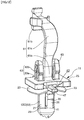
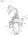
- a clip 11, and a pillar garnish fixing structure 1 for fixing a pillar garnish to a body using the clip in a case where the clip 11 is a tether clip, according to the present application will be explained with reference to FIGS. 1-15 , FIG. 18 , (a), (b) and (c) of FIG. 19 , (a) of FIG. 20 and FIG. 21 . Since a main portion of the pillar garnish fixing structure 1 is the clip 11, the main portion of the clip 11 is the same as the main portion of the pillar garnish fixing structure 1.
- FIGS. 1-13 and FIGS. 18-20 illustrate the clip 11, and FIGS. 14 and 15 illustrate the pillar garnish fixing structure 1.
- FIGS. 1-4 and FIGS. 18-21 illustrate a first embodiment of the present application
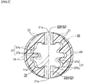
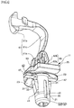
- FIGS. 5 - 8 illustrate a second embodiment of the present application
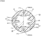
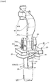
- FIGS. 9 -12 illustrate a third embodiment of the present application
- FIGS. 13 -15 and FIGS. 19-21 are applicable or substantially applicable to all embodiments of the present application. Portions common to all embodiments of the present application are denoted with the same reference numerals over all embodiments of the present application.
- "FR" illustrates a front direction of a vehicle
- "IN” illustrates an inward direction of a right-left direction of the vehicle.
- FIGS. 1-4 and FIGS. 18 -21 a case where the clip 11 is a tether clip (denoted with the same reference numeral as the clip) is shown.
- the clip 11 may be a clip other than the tether clip. More particularly, the clip 11 may be a normal fixing clip for fixing a CSA to the body.
- FIG. 13 illustrates a relationship between a configuration of the clip 11 of the present application and a configuration of the comparison clip 111.
- (a) shows the clip 11 of the present application
- (b) shows the comparison clip 111.
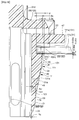
- FIGS. 14 and 15 illustrate a pillar garnish fixing structure 1 for fixing a pillar garnish 81 to a body 91 using the clip 11.
- the clip 11 is made from a resin having a deformability.
- the resin is, for example, polyhexamethylene adipamide. However, so long as the resin has a necessary strength, a resin other than polyhexamethylene adipamide may be used.
- the clip 11 has a center axis line 11a of the clip.
- the clip 11 is provided with a single seat 25, a single shaft 21 ("a shaft” may be called as “a leg portion", “a leg” or “a coupling portion to the body") extending away from the seat 25 and at least one pair of engagement hooks 31.
- the engagement hook 31 extends toward the seat 25 from a hook connecting portion 41 spaced from the seat 25 in an axial direction of the shaft 21.
- the engagement hook 31 may include a free end.
- a plurality of pairs of engagement hooks 31 may be provided.
- a pair of engagement hooks 31 is provided.
- the clip 11 may include an elastic spacer 23.
- the clip 11 includes the elastic spacer 23.
- the elastic spacer 23 may be manufactured integrally with the clip 11 as shown in the drawings or may be manufactured separately from the clip 11, though not shown in the drawings.
- the shaft 21 is perpendicular to the seat 25.
- a center axis line of the shaft 21 coincides with the center axis line 11a of the clip 11.
- the shaft 21 is hollow.
- a configuration of a cross section of the shaft 21 is substantially circular or substantially rectangular. The rectangle may be a square.
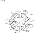
- Each of a pair of openings is formed at the hollow shaft 21 and is defined by a slit 43.
- the openings are formed at portions of the hollow shaft 21 located on opposite sides of the center axis line 11a of the clip and opposing each other.
- each of the pair of engagement hooks 31 is provided at each of the pair of openings. The engagement hooks 31 oppose each other in a direction perpendicular to an axial direction of the clip.
- each engagement hook 31 is connected to a wall of the shaft 21 at the hook connecting portion 41 located at an opposite seat-side end of the engagement hook 31.
- Each engagement hook 31 is separated from the shaft 21 and the seat 25 by an inverted U-letter shaped slit 43 except the hook connecting portion 41.
- the inverted U-letter shaped slit 43 exists between the engagement hook 31 and the shaft 21 connected by the seat 25 except the hook engagement portion 41.
- An axial position of an end of the slit 43 further from the seat 25 and an axial position of the hook connecting portion 41 coincide with each other in the axial direction of the shaft.
- the engagement hook 31 can elastically rotate in a direction toward-away from the center axis line 11a of the clip, i.e., in a falling-rising direction.
- "Rc" shows a hypothetical rotational deformation center of the engagement hook 31.
- a deformation promoting portion 53 is formed at each of a pair of shaft wall portions 21a (shown in FIG. 2 ) opposing each other in a diametrical direction perpendicular to a direction in which the pair of engagement hooks 31 are opposed.
- the deformation promoting portion 53 is provided for promoting deformation of the hook connecting portion 41 and a hook root portion 31a connected to the hook connecting portion 41 in a direction toward the center axis line 11a of the clip and in the direction in which the pair of engagement hooks 31 oppose each other, when the shaft 21 is inserted into a clip fixing aperture 93 formed at a body 91 and is pushed by a rim of the body defining the clip fixing aperture 93.
- the hook root portion 31a is defined as a hook portion (a) connected to the hook connecting portion 41 from a side of the engagement hook 31 and (b) extending from the hook connecting portion 41 to a position spaced from the hook connecting portion 41 by a half of a distance (M- ⁇ M) between the hook connecting portion 41 and a body engagement surface 31b of the engagement hook 31.
- the distance (M- ⁇ M) between the hook connecting portion 41 and the body engagement surface 31b of the engagement hook 31 is shorter than a distance "M" between the hook connecting portion 141 and the body engagement surface 131b of the comparison clip 111 by the amount " ⁇ M".
- the deformation promoting portion 53 allows the shaft portion connected to the hook connecting portion 41 from the side opposite the engagement hook 31 to be deformed toward the center axis line 11a of the clip in the direction in which the pair of engagement hooks 31 are opposed, when the shaft 21 is inserted into the clip fixing aperture 93 of the body.
- the shaft portion connected to the hook connecting portion 41 from the side opposite the engagement hook 31 can pass through the clip fixing aperture 93.
- the deformation promoting portion 53 extends in the axial direction of the shaft 21.
- the deformation promoting portion 53 extends in opposite directions away from an axial shaft position corresponding to the hook connecting portion 41 in the axial direction of the shaft 21.
- the deformation promoting portion 53 may be any one of an elongated aperture 53A, a wall thickness decreased portion 53B and a wall cut portion (which may be called as a split) 53C, as will be described later.
- the pair of engagement hooks 31 include inside surfaces 35 opposing each other and outside surfaces opposite the inside surfaces 35. Each inside surface 35 opposes the center axis line 11a of the clip.
- the pair of engagement hooks 31 define a space 39 (shown in (a) of FIG. 13 ) therebetween.
- the space 39 is an interior of the hollow shaft 21.
- the space 39 extends in the direction away from the seat 25 and opens to an outside of the shaft at the tip end of the shaft.
- a convexity-concavity 37 convex and concave in the direction in which the pair of engagement hooks 31 oppose each other is formed at opposing inside surfaces 35 of the pair of engagement hooks 31.
- the convexity-concavity 37 includes a convexity 37a and a concavity 37b.
- the convexity 37a formed at one of the pair of engagement hooks 31 enters the concavity 37b formed at the other of the pair of engagement hooks 31.
- rotationally deformable amounts of the pair of engagement hooks 31 in the directions to approach each other are increased compared with a case where no convexity-concavity 37 is provided.
- the convexity 37a operates as a reinforcing rib, a bending rigidity of each of the pair of engagement hooks 31 in the rotational direction is increased.
- the convexity-concavity 37 is formed from the seat-side end of the engagement hook 31 to the opposite seat-side end of the shaft 21, over both of the inside surface of the engagement hook 31 and an inner surface 27 of the shaft 21, as shown in (a) of FIG. 13 .
- the convexity-concavity 37 is formed over both of an entire length of the engagement hook 31 and a shaft portion from the hook connecting portion 41 of the engagement hook 31 to a tip of the shaft 21.
- Each of the convexity 37a and the concavity 37b of the convexity-concavity 37 extends straight in the axial direction of the clip 11 and is molded at the same molding step as that of the clip 11.
- each of the pair of engagement hooks 31 includes a protrusion 45 and an engagement releasing portion 47 (which may be called as a hook handling portion).
- the protrusion 45 and the engagement releasing portion 47 are spaced from each other in the axial direction of the clip.
- the protrusion 45 protrudes more than the outer surface of the shaft 21 in the direction away from the center axis line 11a of the clip.
- a portion of the engagement hook 31 which protrudes more than the outer surface of the shaft 21 in the direction away from the center axis line 11 a of the clip is called as the protrusion 45.
- the protrusion 45 includes an inclined surface 49 extending in a direction from the hook connecting portion 41 toward the seat 25-side end of the engagement hook 31 and away from the center axis line 11a of the clip, at least at a portion of the protrusion 45 in a direction along the center axis line 11a of the clip.
- the inclined surface 49 slides relative to the inside surface of the clip fixing aperture 93 when the clip 11 is inserted into the clip fixing aperture 93.
- an inclination-starting point 59 of the inclined surface 49 is located at a position spaced more from the seat 25 than the hook connecting portion 41 by an amount " ⁇ E" ( ⁇ E > 0).
- the outside surface of the engagement hook 31 protrudes more outward than the outer surface 29 of the shaft 21 by an amount " ⁇ T" in a radial direction of the shaft 21 at an axial shaft position corresponding to the hook connecting portion 41 in the axial direction of the shaft. Therefore, a thickness of the engagement hook 31 at the hook connecting portion 41 is thicker than a thickness "T" of the hook connecting portion 141 of the comparison clip 111 by the amount " ⁇ T" and becomes "T + ⁇ T". In spite that the thickness of the engagement hook 31 at the hook connecting portion 41 is increased, the engagement hook 31 can pass through the clip fixing aperture 93 because the hook connecting portion 41 can be moved toward the center axis line 11a of the clip by the deformation promoting portion 53.
- a thickness of the hook root portion 31a connected to the hook connecting portion 41 is increased to be larger than a thickness of the hook root portion 131a of the comparison clip 111 by a difference between a broken line (corresponding to the comparison clip) and a full line (corresponding to the present application) in FIG. 18 .
- a distance between the outside surfaces 33 of the pair of engagement hooks 31 at the hook root portions 31a is increased to be larger than a distance between the outside surfaces 133 of the pair of engagement hooks 131 of the comparison clip 111 at the hook root portions 131a. More particularly, as illustrated in (a) of FIG.
- the distance "d" between the outside surfaces 33 of the pair of engagement hooks 31 at the hook connecting portions 41 in the free state of the clip 11 is designed to be larger than a diameter "D" of the clip fixing aperture 93 of the body 91. Therefore, a distance between the outside surfaces 33 of the pair of engagement hooks 31 at the hook root portions 31a in the free state of the clip 11 is larger than the diameter "D" of the clip fixing aperture 93 of the body 91, because the distance between the outside surfaces 33 of the pair of engagement hooks 31 at the hook root portions 31a is larger than the distance between the outside surfaces 33 of the pair of engagement hooks 31 at the hook connecting portions 41.
- the hook connecting portion 41 and the hook root portion 31a can pass through the clip fixing aperture 93, because due to the deformation promoting portion 53, the hook connecting portion 41 and the hook root portion 31 a can be moved toward the center axis line 11a of the clip and the engagement hook 31 can rotate about the hypothetical rotational deformation center "Rc" toward the center axis line 11a of the clip.
- an axial length of the slit 43 is made smaller than that of the slit of the comparison clip 111, so that a position of the hook connecting portion 41 is shifted toward the seat 25.
- the hook connecting portion 41 is located closer to the seat 25 than the rotational deformation center "Rc"' of the comparison clip 111.
- the hook connecting portion 141 is located equal to or further from the seat 25 than the rotational deformation center "Rc"' of the comparison clip 111.
- the hypothetical rotational deformation center “Rc” is located further from the seat 25 than the hook connecting portion 41. More particularly, the hypothetical rotational deformation center “Rc” of the engagement hook 31 is located at or in the vicinity of the tip end of the shaft 21. In contrast, in the comparison clip 111, the rotational deformation center "Rc"' of the engagement hook 131 is located at the hook connecting portion 141 or at a position slightly closer to the seat 125 than the hook connecting portion 141.
- the hypothetical rotational deformation center "Rc" of the engagement hook 31 is located closer to the end (the tip) of the engagement hook 131 than the rotational deformation center "Rc"' of the comparison clip 111.
- the hook connecting portion 41 is possible not only to be rotatably deformed but also to be deformed in a direction parallel to the seat 25.
- the hypothetical rotational deformation center "Rc" of the engagement hook 31 is shifted to a side further from the seat 25 (a lower side in the drawing) than the rotational deformation center "Rc"' of the comparison clip 111.
- the hook root portion 31a is made thicker than the hook root portion 131a of the comparison clip and the length of the engagement hook 31 is made short, the bending rigidity of the engagement hook 31 is increased. Due to the increase in the bending rigidity, the hypothetical rotational deformation center "Rc" of the engagement hook 31 is more shifted to the side further from the seat 25 than the rotational deformation center "Rc"' of the comparison clip 111.
- an outer surface of the protrusion 45 i.e., an outer surface 33 of the engagement hook 31
- the engagement hook 31 is rotated about the hypothetical rotational deformation center "Rc" to approach the center axis line 11a of the clip.
- the engagement hook 31 springs back to an original position.
- a seat-opposing surface (i.e., a body engagement surface) 31b of the protrusion 45 is brought into engagement with a rim portion of the body defining the clip fixing aperture 93 in the axial direction of the clip, whereby the clip 11 is prevented from being drawn-out from the clip fixing aperture 93.
- an engagement amount of the engagement hook 131 with the rim portion of the body defining the clip fixing aperture 193 of the comparison clip 111 having no deformation promoting portion 53 before the engagement hook 131 is deformed in a rotational direction is expressed as "a"
- an engagement amount of the engagement hook 31 with the rim portion of the body defining the clip fixing aperture 93 before the engagement hook 31 is deformed in a rotational direction can be decreased by (0.1-0.3) X a from that amount "a" of the comparison clip 111.
- a reason for the limitation of (0.1 X a) is that if a decrease in the engagement amount is smaller than (0.1 X a), an effect due to the decrease in the engagement amount cannot be sufficiently obtained.
- a reason for the limitation of (0.3 X a) is that if a decrease in the engagement amount is larger than (0.3 X a), the engagement amount is too small to obtain a sufficient axial length of the engagement hook along the breakage plane S (shown in (c) of FIG. 19 ) and to get a sufficient strength.
- FIG. 18 and (a) of FIG. 13 illustrate a case where the engagement amount of the engagement hook is decreased by (0.2 X a) and is (0.8 X a).
- the engagement releasing portion 47 is connected to the seat-side end of the engagement hook 31 and extends in the direction away from the center axis line 11 a of the clip.
- An end of the engagement releasing portion 47 further from the center axis line 11a of the clip is located further from the center axis line 11 a of the clip than an outer end of the protrusion 45.
- the end of the engagement releasing portion 47 further from the center axis line 11 a of the clip is located further from the center axis line 11 a of the clip than an outer end of the seat 25 so that the engagement releasing portion 47 can be easily handled.
- the engagement releasing portions 47 of the pair of engagement hooks 31 are pushed in directions in which the engagement releasing portions 47 approach each other so that a distance between the outer ends of the protrusions 45 becomes equal to or smaller than the inside diameter of the clip fixing aperture 93. Then, the clip 11 is pulled in the axial direction of the clip and the shaft 21 is drawn out from the clip fixing aperture 93.
- the pillar garnish fixing structure 1 includes the tether clip 11, a pillar as a body (reference numeral 11 is used for the pillar), and a pillar garnish 81 to be fixed to the pillar 91 using the tether clip 11.
- the pillar garnish 81 is made from a plastic having a hardness equal to or harder than that of the clip 11. As illustrated in FIGS. 14 and 15 , the pillar garnish 81 is coupled to an inner panel 91a of the pillar 91 using the tether clip 11.
- the pillar garnish 81 includes a garnish body 83 and a tether housing portion 85. At a bottom wall 85a of the tether housing portion 85, a rectangular tether inserting aperture 87 is formed.
- a rounded or folded CSA 89 is disposed at a space surrounded by the inner panel 91a of the pillar 91 and the garnish body 83.
- the CSA 89 is deployed at the time of a side collision of the vehicle or a rollover and pushes the pillar garnish 81 in a direction away from the pillar 91.
- FIG. 15 shows a portion of the CSA 89 which is being deployed.
- the tether clip 11 includes a tether 61 and an engagement holding portion 63.
- the tether 61 and the engagement holding portion 63 can be the same as a tether and an engagement holding portion 63 of the comparison tether clip 111.
- the tether 61 includes a rising portion 61a rising from the seat 25 in a direction opposite the shaft 21, an anchor 61b provided at an end of the tether further from the seat 25 and a connecting portion 61b connecting the rising portion 61a and the anchor 61b.
- the connecting portion 61c may be curved. A direction along which the connecting portion 61c is curved may be a direction perpendicular to a longitudinal direction of the pillar garnish 81, or a longitudinal direction of the pillar garnish 81.
- the anchor 61b has a rectangular configuration smaller than the tether inserting aperture 87 formed at the tether housing portion 85 of the pillar garnish 81.
- a phase of the anchor 61b and a phase of the tether inserting aperture 87 are made coincident with each other, and then the anchor 61b is inserted into the tether inserting aperture 87.
- the tether clip 11 is rotated about the center axis line 11a of the clip by 90 degrees so that the tether clip 11 cannot be drawn out from the tether housing portion 85.
- FIG. 14 illustrates a state where the pillar garnish 81 coupled with the tether clip 11 has been coupled to the pillar 91.
- the engagement holding portion 63 rises from the seat 25 in a direction opposite the shaft 21.
- the engagement holding portions 63 are provided at opposite sides of the rising portion 61 a of the tether 61.
- the engagement holding portions 63 are spaced from the rising portion 61a.
- the engagement holding portion 63 includes a rising portion 63a rising from the seat 25 by an amount substantially equal to a thickness of the bottom wall 85a of the tether housing portion and a bulged portion 63b further extending from a tip of the rising portion 63a in the direction away from the seat 25 and bulged in a direction perpendicular to the rising direction of the rising portion 63a.
- the bulged portion 63b is formed hollow so that the bulged portion 63b has an elasticity in the direction perpendicular to the rising direction of the rising portion 63a.
- the engagement holding portion 63 When coupling the tether clip 11 to the pillar garnish 81, the engagement holding portion 63 is pushed into the tether inserting aperture 87 of the tether housing portion 85. At that time, the bulged portion 63b is elastically deformed in a bulging amount decreasing direction, whereby the bulged portion 63b can pass through the tether inserting aperture 87 to an interior of the tether housing portion 85. Upon having passed through the tether inserting aperture 87, the bulged portion 63b elastically returns to an original position (a position of a free state of the bulged portion) and holds the bottom wall of the tether housing portion 85 between the bulged portion 63b and the seat 25. While the engagement holding portion 63 is holding this state, the tether clip 11 is installed to the pillar 91.
- a rim portion of the tether housing portion defining the tether inserting aperture 87 pushes the bulged portion 63a of the engagement holding portion 63 in a drawing-out direction, thereby deforming the bulged portion 63a in the bulging amount decreasing direction.
- the bulged portion 63a passes through the tether inserting aperture 87 and the bottom wall 85a of the tether housing portion 63 is disengaged from the bulged portion 63a.
- the pillar garnish 81 is moved in the direction away from the pillar 91 until the anchor 61b of the tether 61 is brought into contact with the rim portion of the bottom wall 85a of the tether housing portion defining the tether inserting aperture 87, whereby a space for deployment of the CSA 89 is formed between the pillar garnish 81 and the inner panel 91a.
- the anchor 61b contacts the rim portion of the bottom wall 85a defining the tether inserting aperture 87, the pillar garnish 81 cannot move further, so that the pillar garnish 81 is prevented from moving freely toward the passenger compartment.
- the CSA 89 is deployed into the passenger compartment to a position between a passenger and a side door through the space formed between the inner panel 91a and the garnish 83, thereby restricting and protecting a head of the passenger.
- the tether clip 11 allows the pillar garnish 81 to move by a predetermined amount thereby forming the deployment space, but restricts the pillar garnish 81 to move more than that predetermined amount.
- the clip 11 according to the first embodiment of the present application further includes the following structures:
- the deformation promoting portions 53 are provided at the shaft 21, when an outside surface of each of the pair of engagement hooks 31 is pushed by the inside surface of the rim portion of the body defining the clip fixing aperture 93, the hook connecting portion 41, the hook root portion 31a and a portion of the shaft connecting to the hook connecting portion 41 from a side opposite the hook root portion 31a can be deformed in the direction toward the center axis line 11a of the clip. As a result, the hook connecting portion 41, the hook root portion 31a and the portion of the shaft connecting to the hook connecting portion 41 from the side opposite the hook root portion 31a can pass through the clip fixing aperture 93.
- the hypothetical rotational deformation center "Rc" of the engagement hook 31 at the time of passing through the clip fixing aperture 93 is shifted in a direction further from the seat 25, i.e., downward in the drawing, than the hypothetical rotational deformation center "Rc"' of the engagement hook 131 of the comparison clip 111.
- the connecting portion 41 can be deformed toward the center axis line 11a.
- the hook connecting portion 41, the hook root portion 31a and the portion of the shaft connecting to the hook connecting portion 41 from the side opposite the hook root portion 31a can pass through the clip fixing aperture 93.
- the rigidity and strength of the engagement hook 31 at the hook root portion 31a can be increased, by increasing the thickness of the engagement hook 31 at the hook root portion 31a. Due to the increase in the rigidity and strength, a deformation of the engagement hook 31 when the CSA is deployed and a large load is loaded on the engagement hook 31 is changed from (e) of FIG.
- a movement amount "h” of an upper corner 131 c of an outside surface of engagement hook 131 in an axial direction of the shaft when the upper corner 131 is rotated about the hypothetical rotational deformation center "Rc"' drawing an arc is (0.26 X a).
- a movement amount "h” of an upper corner 31 c of an outside surface of the engagement hook 31 in the axial direction of the shaft when the upper corner 31 is rotated about the hypothetical rotational deformation center "Rc" drawing an arc is (0.09 X a).
- the excess-inserting amount as illustrated in FIG.
- the clip 11 can be inserted to the hook engagement point (P") where the reaction force (F") of the elastic spacer 23 is (1/2 ⁇ F-2/3 ⁇ F), due to a quickness with which the clip 11 passes over a peak (F0) of an inserting load of the engagement hook 31 when the clip 11 is inserted into the clip fixing aperture 93. Therefore, a half-fitting and a non-fitting of the pair of engagement hooks 31 can be prevented from happening. As a result, a reliability of installing the clip 11 to the body is improved.
- the engagement hook 31 After the engagement hook 31 has engaged the body, the engagement hook 31 returns to a free state and the shaft 21 is moved in a drawing direction by the amount of "h" of the upper corner 31c of the outside surface of the engagement hook 31 in the axial direction of the shaft. Due to the decrease in the movement amount "h” from (0.26 ⁇ a) to (0.09 ⁇ a), i.e., due to the decrement of (0.17 ⁇ a), the reaction force of the elastic spacer 23 also is decreased. As illustrated in FIG. 21 , with the comparison clip 111, the reaction force of the elastic spacer is decreased from (F) to (F').
- the reaction force (F') also of the elastic spacer of the present application can be made larger than the reaction force (F') of the elastic spacer of the comparison clip. Due to making the reaction force (F') of the elastic spacer large, tilting of the clip 11 relative to the body 91 during a normal use can be suppressed. As a result, the previously described problems (ii) regarding easiness of installing the clip to a body, reliability of installing the clip to the body, and suppressing tilting of the clip are solved or can be solved.
- the increase in the thickness of the engagement hook at each of the hook connecting portion 41 and the hook root portion 31a is obtained not by bulging the inside surface 35 toward the center axis line 11a of the clip, but by bulging the outside surface 33 outward. Due to the increase in the thickness of the engagement hook at each of the hook connecting portion 41 and the hook root portion 31 a, the rigidity of the engagement hook at each of the hook connecting portion 41 and the hook root portion 31a is increased. As a result, when a deployment load of the CSA is loaded on the body engagement surface 31b, a large bending deformation as shown in (e) of FIG. 19 is suppressed from being generated.
- the inside surface 35 of the engagement hook 31 is not bulged toward the center axis line 11 a of the clip, when each of the pair of engagement hooks 31 is deformed to fall inwardly at the time of installing the clip 11 to the body 91 or removing the clip 11 from the body 91, the inside surfaces 31d of the seat-side ends of the engagement hooks 31 are suppressed from interfering with each other.
- an over-stroke of the clip from the normal-fitting position at the time of fixing the clip to the body can be decreased.
- the clip 11 is a clip of a type including the engagement releasing portion 47, a length of the engagement hook 31 from the hook connecting portion 41 to the engagement releasing portion 47 is increased by an increment due to the engagement releasing portion 47.
- the hypothetical rotational deformation center "Rc" of the engagement hook 31 is positioned far away from the seat, a falling angle of the engagement hook 31 caused when the engagement hook 31 is deformed to inwardly incline is decreased from (K) in the case of the comparison clip 111 to (o.42 ⁇ K) of the present embodiment, as illustrated in FIG. 13 . Due to the decrease in the falling angle of the engagement hook 31 also, the inside surfaces 31d of the seat-side ends of the engagement hooks 31 are suppressed from interfering with each other.
- FIGS. 5 - 8 and (a) of FIG. 13 illustrate the clip 11 of the second embodiment of the present application.
- FIGS. 14 and 15 are applied to the pillar garnish fixing structure 1 of the second embodiment of the present application using the clip 11.
- the deformation promoting portion 53 is constructed of a wall thickness decreased portion 53B.
- the clip 11 of the second embodiment has the same structures, operations and technical advantages as those of the first embodiment except the deformation promoting portion 53.
- the structures, operations and technical advantages which are applicable to all embodiments of the present application, among those of the first embodiment are applied to those of the second embodiment.
- the second embodiment further has the following structures, operations and technical advantages:
- the deformation promoting portion 53 is constructed of the wall thickness decreased portion 53B and the hook connecting portion 41 is located between the axially opposite ends of the wall thickness decreased portion 53B in the axial direction of the shaft, the shaft 21 can be easily deformed at a range of the shaft where the wall thickness decreased portion 53B is provided. Accordingly, the force of inserting the shaft 21 into and removing the shaft 21 from the clip fixing aperture 93 is smaller than the force of inserting and removing of the comparison clip 93 having no deformation promoting portion 53.
- the features of installing the clip 11 and the pillar garnish 81 to the inner panel 91a of the pillar are better than those of the comparison clip 111 having no deformation promoting portion 53.
- FIGS. 9-12 and (a) of FIG. 13 illustrate the clip 11 of the third embodiment of the present application.
- FIGS. 14 and 15 are applied to the pillar garnish fixing structure 1 of the third embodiment of the present application using the clip 11.
- the deformation promoting portion 53 is constructed of a wall cut portion 53C.
- the clip 11 of the third embodiment has the same structures, operations and technical advantages as those of the first embodiment except the deformation promoting portion 53.
- the structures, operations and technical advantages which are applicable to all embodiments of the present application, among those of the first embodiment are applied to those of the third embodiment.
- the third embodiment further has the following structures, operations and technical advantages:
- the deformation promoting portion 53 is constructed of the wall cut portion 53C and the wall cut portion 53C extends to the tip end of the shaft 21 to open to the outside, the shaft 21 can be easily deformed at a range of the shaft where the wall cut portion 53C is provided. Accordingly, the force of inserting the shaft 21 into and removing the shaft 21 from the clip fixing aperture 93 is smaller than (and is decreased to, for example, about 1/3 -1/4 of) the force of inserting and removing of the comparison clip 93 having no deformation promoting portion 53. As a result, in the clip 11 and the pillar garnish fixing structure 1 using the clip 11, the features of installing the clip 11 and the pillar garnish 81 to the inner panel 91a of the pillar become good.
Landscapes
- Engineering & Computer Science (AREA)
- General Engineering & Computer Science (AREA)
- Mechanical Engineering (AREA)
- Insertion Pins And Rivets (AREA)
- Connection Of Plates (AREA)
- Air Bags (AREA)
- Vehicle Interior And Exterior Ornaments, Soundproofing, And Insulation (AREA)
Abstract
Description
- This application relates to a clip and a pillar garnish fixing structure using the clip. A pillar garnish fixing structure may be called a pillar garnish fixing apparatus.
-
Patent Document 1 discloses a clip and a pillar garnish fixing structure using the clip. The conventional clip fixes a pillar garnish housing a curtain airbag, to a pillar and prevents the pillar garnish from being freely moved into a passenger compartment when the curtain airbag is deployed. "Curtain Airbag" may be called as "CSA", which means "Curtain Shield Airbag". - In
FIGS. 16-17 ,(b) of FIG. 13 ,(d), (e) and (f) of FIG. 19 and(b) of FIG. 20 , broken lines show acomparison clip 111. Thecomparison clip 111 is a reference clip for comparison with a clip of the present application and is not a known conventional clip. Portions of the comparison clip corresponding to portions of the present application clip are denoted with reference numerals added with "1" at tops (left sides) of the reference numerals of the portions of the present application clip. For example, reference numeral "131" in the comparison corresponds to reference numeral "31" in the present application. - The
comparison clip 111 includes aseat 125, ashaft 121 extending in a direction away from theseat 125 and a pair ofengagement hooks 131 opposing each other. Each of the pair ofengagement hooks 131 is connected to theshaft 121 at ahook connecting portion 141 located at an opposite seat-side end of theengagement hook 131 and is separated from theshaft 121 by a slit except thehook connecting portion 141. Theengagement hook 131 extends from thehook connecting portion 141 toward theseat 125 and ends in the form of a free end. In thecomparison clip 111, theshaft 121 is circumferentially continuous at the same axial position as thehook connecting portion 141. Adeformation promoting portion 53 of the present application later described, for promoting deformation of thehook connecting portion 141 toward a center axis line of the clip such as an elongated aperture is not provided at a pair of shaft wall portions opposing each other in a diametrical direction perpendicular to a direction in which the pair ofengagement hooks 131 are opposed. Thehook connecting portion 141, which is located at the same axial position as an end of the slit, is located at a position equal to a rotational deformation center Rc' of theengagement hook 131 or further from theseat 125 than the rotational deformation center Rc'. - Patent Document 1:
Patent Publication JP 2013-180725 - However, there are the following problems with the conventional clip:
- The problems with the clip of
Patent Document 1 will be explained using thecomparison clip 111, because the problems are similar to those of thecomparison clip 111.- (i) It is difficult to obtain both a desired strength of the
engagement hook 131 and a serviceability of the clip. - (ii) In order to easily install the
clip 111 to a body, installing theclip 111 to the body with a high reliability (without being accompanied by a half-fitting or a non-fitting), and suppressing a rotational play of theclip 111 relative to the body, further improvements are desired.
- (i) It is difficult to obtain both a desired strength of the
- The above problems will be discussed in more detail below.
- When a large load such as a deployment load of the CSA is loaded on the
engagement hook 131 from above in (b) ofFIG. 13 , a relatively large bending deformation may occur at aroot portion 131a of the engagement hook as shown in (e) ofFIG. 19 . Since the wall of theshaft 121 is circumferencially continuous at the same axial position as thehook connecting portion 141, thehook connecting portion 141 is unlikely to be deformed toward acenter axis line 111a of the clip as illustrated in (b) ofFIG. 13 . As a result, abody engagement surface 131b of theengagement hook 131 is inclined to a large extent causing it to be lowered in an outward direction so that a shear-breakage plane S' extending in an axial direction of the shaft (simply, "axial direction", hereinafter) is decreased in length in the axial direction. Therefore, a durability of the clip against a drawing-out load is reduced, and the clip is likely to be broken along the shear-breakage plane S' as illustrated in (f) ofFIG. 19 .Reference numeral 132 shows a broken piece. - In order to decrease the bending deformation at the
root portion 131a of the engagement hook, in (b) ofFIG. 13 , it will be necessary to increase a thickness "T" of theengagement hook 131 at thehook connecting portion 141 to thereby increase a thickness of theroot portion 131a. In this instance, if the thickness "T" of theengagement hook 131 is increased by outwardly bulging an outside surface of theengagement hook 131, theclip 111 is unlikely to be inserted into aclip fixing aperture 193. If the thickness "T" of theengagement hook 131 is increased by inwardly bulging an inside surface of theengagement hook 131, when the pair of engagement hooks are inwardly rotated about thehook connecting portion 141, sinceupper corners 131d of the inside surfaces of the pair ofengagement hooks 131 interfere with each other and rotating angles of the pair of engagement hooks are restricted, theclip 111 is unlikely to be inserted into theclip fixing aperture 193. As a result, it is difficult to satisfy at the same time both a strength (therefore, a thickness) of theengagement hook 131 and an easiness of passing theengagement hook 131 through theclip fixing aperture 193 at the times of installing and service. - The
engagement hook 131 rotates in a direction toward or away from thecenter axis line 111a about the rotational deformation center "Rc"' which is located at thehook connecting portion 141 or slightly above the hook connecting portion as shown in (b) ofFIG. 20 . At that time, anupper corner 131c of the outside surface of theengagement hook 131 rotates about the rotational deformation center "Rc"' drawing an arc "C"' and is shifted to a position located higher by an amount "h" in the axial direction of the shaft than an original position of thecorner 131c before rotation of theengagement hook 131. When "a" is defined as an engagement amount of theengagement hook 131 of the comparison clip with abody panel 191a (simply, "body", hereinafter), the above amount "h" is calculated to be 0.26a. Therefore, theclip 111 has to be excess-inserted into theclip fixing aperture 193 in the axial direction of the shaft by the amount "h" in order that theengagement hook 131 can engage thebody 191. -
FIG. 21 is a graph illustrating an insertion load versus insertion amount characteristic when theclip 111 is inserted into theclip fixing aperture 193. At an early stage of insertion, anoutside surface 133 of the engagement hook 131 contacts a corner and an inside surface of the rim of the body defining theclip fixing aperture 193, so that an engagement hook insertion load characteristic "W2" having a mountain shape shown in one-dotted chain line appears. On the other hand, an elastic spacer 123 (shown inFIGS. 16 and17 ) is provided to theclip 111, in order to remove a play of theclip 111 relative to thebody 191 when theclip 111 has been installed to thebody 191. Therefore, when theelastic spacer 123 begins to contact the rim of the body defining theclip fixing aperture 193 at a final stage of insertion, a reaction force characteristic "W3" of the elastic spacer shown in a broken line inFIG. 21 and rising steeply appears. - As illustrated in
FIG. 21 , a hook engagement point "P" where the hook begins to engage the body is located at a position deeper than a hook normal fitting point "P"' (i.e., a position of the body engagement surface of the engagement hook in the axial direction of the shaft when the engagement hook is at a normal-fitting with the body) by the above-described excess-inserting amount "h" in a clip insertion direction. An elastic spacer reaction force "F" at the hook engagement point "P" is larger than an elastic spacer reaction force "F"' (which is the same as an elastic spacer reaction force at a normal operating condition ofFIG. 13 ) operating at the hook normal fitting point "P"' by an amount ("F" - "F"'). In this instance, the elastic spacer reaction force "F"' operating at the hook normal fitting point "P"' is a load necessary to suppress a play of the clip relative to the body. The elastic spacer reaction force "F" at the hook engagement point "P" is a load determined from a working standard (i.e., a standard load of a working specification). In order to excess-insert theclip 111 by the amount "h" from the point "P"' to the point "P", since the clip inserting force "F" is larger than the elastic spacer reaction force "F"', it is necessary to push the clip at a large force, which is accompanied by a difficulty in an installing work. Further, as illustrated inFIG. 21 , since there is no click feeling in a clip inserting load in the vicinity of the hook engagement point "P", it is difficult to acknowledge from a change in the inserting load that theengagement hook 131 has engaged thebody 191. Therefore, it is difficult to distinguish a case where insertion of the clip is stopped in the vicinity of the peak "F0" of the engagement hook inserting load at the early stage of insertion from a case where the engagement hook has passed the hook engagement point "P" and has engaged the body. As a result, even if a half-fitting state where only one engagement hook of the pair ofengagement hooks 131 engages the body or a non-fitting state where both engagement hooks of the pair ofengagement hooks 131 do not engage the body has occurred, it is difficult to detect it. Therefore, reliability of installing the clip to the body is decreased. - Further, when the engagement hook 131 springs back to its free position after the
engagement hook 131 has engaged thebody 191, theshaft portion 121 is moved in a drawing-out direction by the excess-inserting amount "h" due to a reaction force of theelastic spacer 123, so that the reaction force of theelastic spacer 123 is decreased from "F" to "F"' inFIG. 21 . Since the force "F" is determined from the working standard and can not be large, and since the excess-inserting amount "h" is as large as 0.26 X a, the force "F"' is forced to be small. As a result, it will be disadvantageous to suppress tilting of theclip 111 relative to the body, when the engagement hook is at a normal-fitting state with the body.
In order to decrease the excess-inserting amount "h", it may be effective to decrease an engaging amount "a" of theengagement hook 131 with thebody 191. However, in thecomparison clip 111, as shown in (e) ofFIG. 19 , when a large load is loaded on theengagement hook 131, thebody engagement surface 131b of the engagement hook is inclined due to a deformation of thehook root portion 131 a. As a result, a substantial engaging amount of the engagement hook with thebody 191 is decreased. Therefore, it is difficult to decrease the initial engaging amount "h" of the engagement hook with the body. - An object of the present application is to provide a clip and a pillar garnish fixing structure using the clip, where at least one of the following requirements can be achieved:
- Both strength of an engagement hook and serviceability of the clip are satisfied; and
- Easiness of installing the clip to a body, reliability of installing the clip to the body (i.e., reliability of preventing a half-fitting state and a non-fitting state of the clip from happening, and suppressing tilting of the clip) are achieved.
- A clip and a pillar garnish fixing apparatus for achieving the above object can take the aspects or embodiments described below, where reference numerals in brackets correspond to reference numerals shown in the accompanying drawings.
- In a first aspect of the present application, a clip (11) is made from a resin having an elasticity and includes a seat (25), a hollow shaft (21) extending away from the seat (25) and a pair of engagement hooks (31) opposing each other. Each of the engagement hooks (31) is connected to the shaft (21) at a hook connecting portion (41) located at an opposite seat-side end of the engagement hook (31), is separated from the shaft (21) and the seat (25) by a slit (43) except for the hook connecting portion (41), and extends from the hook connecting portion (41) toward the seat (25).
In the clip, a deformation promoting portion (53) for promoting deformation of the hook connecting portion (41) and a hook root portion connected to the hook connecting portion in a direction toward a center axis line (11a) of the clip when the shaft (21) is inserted into a clip fixing aperture (93) formed at a body (91), is formed at each of a pair of shaft wall portions (21a) opposing each other and located in a diametrical direction perpendicular to a direction in which the pair of engagement hooks (31) are opposed. The deformation promoting portion (53) is constructed of at least one of an elongated aperture (53A), a wall thickness decreased portion (53B) and a wall cut portion (53C). - In a second aspect of the present application, in the first aspect above, the deformation promoting portion (53) extends in an axial direction of the shaft (21) and in opposite directions away from a position corresponding to the hook connecting portion (41) in the axial direction of the shaft.
- In a third aspect of the present application, in the first aspect above, each of the pair of engagement hooks (31) includes a protrusion (45) protruding further in a direction away from the center axis line (11a) of the clip than an outer surface (29) of the shaft (21) when each of the pair of engagement hooks (31) is in a free state. The protrusion (45) includes an inclined surface (49) extending in a direction from the hook connecting portion (41) toward the seat (25)-side end of each of the pair of engagement hooks (25) and away from the center axis line (11a) of the clip, at least at a portion of the protrusion (45) in a direction along the center axis line (11a) of the clip. An inclination-starting point (59) of the inclined surface (49) is located at a position spaced further from the seat (25) than the hook connecting portion (41), whereby an outside surface of each of the pair of engagement hooks protrudes more outward than the outer surface (29) of the shaft (21) in a radial direction of the shaft (21) at an axial shaft position corresponding to the hook connecting portion (41) in the axial direction of the shaft.
- In a fourth aspect of the present application, in any one of the first - third aspects above, a distance (d) between outside surfaces (33) of the pair of engagement hooks (31) at the hook connecting portions (41) is set larger than a diameter (D) of a clip fixing aperture (93) of the body (91).
- In a fifth aspect of the present application, in any one of the first-fourth aspects above, each engagement hook (31) has a hypothetical rotational deformation center "Rc", and the hypothetical rotational deformation center "Rc" is located further from the seat (25) than the hook connecting portion (41).
- In a sixth aspect of the present application, in the fifth aspect above, the hypothetical rotational deformation center "Rc" is located at or in a vicinity of an opposite seat-side end of the shaft (21).
- In a seventh aspect of the present application, in any one of the first-sixth aspects, the clip (11) includes an engagement releasing portion (47) connected to the seat (25)-side end of the each engagement hook (31) and extending in a direction away from the center axis line (11a) of the clip.
- In an eighth aspect of the present application, in any one of the first-seventh aspects, the clip (11) is a tether clip for fixing a pillar garnish (81) to a pillar (91).
- In a ninth aspect of the present application, a pillar garnish fixing structure (1) includes the pillar garnish (81) to be fixed to the pillar (91) using the clip (11) according to the eighth aspect.
- According to the first aspect, the following technical advantages are obtained: Since the deformation promoting portion is provided, the hook connecting portion can be easily deformed in the direction toward the center axis line, so that the hook connecting portion can easily pass through the clip fixing aperture when the clip is inserted into the clip fixing aperture. Further, while maintaining that the hook connecting portion and the root portion of the hook connecting portion can easily pass through the clip fixing aperture, a thickness of the hook connecting portion can be increased whereby a rigidity and a strength of the engagement hook can be increased. As a result, both of the serviceability and the strength of the engagement hook can be satisfied, so that the above problem (i) can be solved.
- Since the deformation promoting portion is provided whereby the hook connecting portion can be deformed in the direction toward the center axis line, the hook connecting portion can be deformed both in a rotational direction and in a direction parallel to the seat. As a result, a rotational deformation center of the engagement hook is shifted in a direction away from the seat from a position located in the vicinity of the hook connecting portion to the hypothetical rotational deformation center located in the vicinity of a tip end of the shaft.
Further, since the rotational deformation center of the engagement hook is shifted to the hypothetical rotational deformation center located in the vicinity of the tip end of the shaft, a movement amount of an upper corner of the outside surface of the engagement hook in the axial direction of the shaft is decreased when the upper corner of the outside surface of the engagement hook is rotated about the hypothetical rotational deformation center drawing an arc. As a result, an excess-inserting amount and an excess-inserting force necessary to cause the engagement hook to engage the body are decreased. Due to the decrease in the excess-inserting force, work to install the clip is improved. Further, it is possible to insert the clip to a normal-fitting position by one pushing action due to a quickness with which the clip can ride over a peak of an inserting load of the inserting amount curve when the clip is inserted into the clip fixing aperture (i.e., a peak of an inserting load when an outside surface of the engagement hook slides relative to an inside surface of the clip fixing aperture). As a result, a half-fitting state and a non-fitting state of the pair of engagement hooks can be suppressed. Therefore, a reliability of installing the clip to the body is improved.
Furthermore, since the movement amount of the upper corner of the outside surface of the engagement hook in the axial direction of the shaft is decreased, the decrease in the reaction force of the elastic spacer, which is caused when the shaft is moved in the drawing-out direction after the engagement hook has engaged the body, is small. As a result, tilting of the clip which may be generated at the normal-fitting state of the engagement hook is suppressed.
As a result, the above-described problem (ii) increased work to install the clip to the body, a reliability of installing the clip to the body, and tilting of the clip, is solved or becomes possible to be solved. - According to the second aspect, since the deformation promoting portion extends from the hook connecting portion in opposite directions in the axial direction of the shaft, the hook connecting portion can be easily deformed in the direction toward the center axis line of the clip, so that the above technical advantages of the first aspect can be surely obtained.
- According to the third aspect, since the inclination-starting point of the inclined surface is located at a position spaced further from the seat than the hook connecting portion, the hook connecting portion can be made thick, so that the technical advantages of the first aspect can be surely obtained.
- According to the fourth aspect, since the distance between the outside surfaces of the pair of engagement hooks at hook connecting portions of the pair of engagement hooks is set larger than the diameter of the clip fixing aperture of the body, the thicknesses of the hook connecting portion and the root portion of the engagement hook are large. Therefore, the rigidness of the hook connecting portion and the root portion of the engagement hook are surely made large, so that deformation of the engagement hook is suppressed when a drawing-out load is loaded on the engagement hook at the time of deployment of the CSA. As a result, an axial length of the engagement hook along the breakage plane of the engagement hook is made sufficiently large, so that a sufficient strength of the engagement hook can be obtained and a durability of the engagement hook against the drawing-out load at the time of deployment of the CSA can be improved.
- According to the fifth aspect, since the hypothetical rotational deformation center "Rc" is located further from the seat than the hook connecting portion, an angle of falling of the engagement hook at the time of inserting the shaft into the clip fixing aperture of the body is made small. As a result, an axial length of the engagement hook along the breakage plane of the engagement hook is made sufficiently large, so that a sufficient strength of the engagement hook can be obtained and a durability of the engagement hook against the drawing-out load at the time of deployment of the CSA can be improved. Further, an excess-inserting amount necessary to cause the engagement hook to engage the body can be made small.
- According to the sixth aspect, since the hypothetical rotational deformation center "Rc" is located at or in the vicinity of the tip end of the shaft further from the seat, those technical advantages according to the fifth aspect can be surely obtained.
- According to the seventh aspect, since the hypothetical rotational deformation center of the engagement hook is shifted to a tip end side of the shaft so that an angle of falling of the engagement hook is made small, an interference between the seat-side ends of the opposing surfaces of the pair of engagement hooks can be suppressed in spite that the lengths of the pair of engagement hooks are increased because the engagement releasing portions are provided.
- According to the eighth aspect, the same technical advantages as those of the first to seventh aspects can be obtained in the tether clip.
- According to the pillar garnish fixing structure according to the ninth aspect, since the pillar garnish is installed to the pillar using the clip according to the eighth aspect, the same technical advantages as those of the eighth aspect can be obtained in the pillar garnish fixing structure. In addition, the following technical advantages are obtained: Since inserting the clip into the clip fixing aperture and drawing-out the clip from the clip fixing aperture become easy, installing the pillar garnish to the pillar and drawing-out the clip from the body at the times of assembly and service become easy. Further, in a case where the thickness and the rigidity at the root portion of the engagement hook are made large, the durability of the clip against the drawing-out load is improved so that free movement of the pillar garnish into the passenger room at the time of deployment of the CSA can be surely suppressed.
-
-
FIG. 1 is a front view of a clip according to a first embodiment of the present application in a state where the clip has been inserted into a clip fixing aperture; -
FIG. 2 is an enlarged cross-sectional view of the clip ofFIG. 1 taken along line 2-2 ofFIG. 1 ; -
FIG. 3 is a perspective view of the clip ofFIG. 1 ; -
FIG. 4 is a perspective view of the clip ofFIG. 1 viewed in a direction different fromFIG. 3 ; -
FIG. 5 is a front view of a clip according to a second embodiment of the present application in a state where the clip has been inserted into a clip fixing aperture; -
FIG. 6 is an enlarged cross-sectional view of the clip ofFIG. 5 taken along line 6-6 ofFIG. 5 ; -
FIG. 7 is a perspective view of the clip ofFIG. 5 ; -
FIG. 8 is a perspective view of the clip ofFIG. 5 viewed in a direction different fromFIG. 7 ; -
FIG. 9 is a front view of a clip according to a third embodiment of the present application in a state where the clip has been inserted into a clip fixing aperture; -
FIG. 10 is an enlarged cross-sectional view of the clip ofFIG. 9 taken along line 10 -10 ofFIG. 9 ; -
FIG. 11 is a perspective view of the clip ofFIG. 9 ; -
FIG. 12 is a perspective view of the clip ofFIG. 9 viewed in a direction different fromFIG. 11 ; -
FIG. 13 is a cross-sectional view illustrating only one engagement hook and its vicinity of the clip of the present application "having a deformation promoting portion" and only one engagement hook and its vicinity of a comparison clip "having no deformation promoting portion", compared with each other, where hatchings for showing a cross section are omitted; -
FIG. 14 is a cross-sectional view of a pillar garnish fixing structure using the clip ofFIG. 1 ; -
FIG. 15 is a cross-sectional view of the pillar garnish fixing structure ofFIG. 14 in a state where a CSA has been deployed; -
FIG. 16 is a perspective view of the comparison clip; -
FIG. 17 is a perspective view of the comparison clip ofFIG. 16 viewed in a direction different fromFIG. 16 ; -
FIG. 18 is a cross-sectional view illustrating a difference between movement amounts of upper corners of outside surfaces of engagement hooks in an axial direction of a shaft, of the clip according to the first embodiment of the present application (shown in a full line) where an engagement amount of the engagement hook with a body panel is decreased by 0.2 X a, and the comparison clip (shown in a broken line); -
FIG. 19 includes the following subsidiary views (a) to (f), where- (a) is a cross-sectional view of the engagement hook where hatchings for showing a cross section are omitted, of the clip according to the first embodiment of the present application where the engagement amount of the engagement hook with the body panel is decreased by 0.2 X a, and the comparison clip, before a load is loaded on the engagement hook;
- (b) is a cross-sectional view of the engagement hook where hatchings for showing a cross section are omitted, of the clip according to the embodiment of the present application before the load is loaded on the engagement hook or at an early stage when the load begins to be loaded on the engagement hook;
- (c) is a cross-sectional view of the engagement hook where hatchings for showing a cross section are omitted, of the clip according to the embodiment of the present application after the load has been loaded on the engagement hook;
- (d) is a cross-sectional view of the engagement hook where hatchings for showing a cross section are omitted, of the comparison clip before the load is loaded on the engagement hook or at an early stage when the load begins to be loaded on the engagement hook;
- (e) is a cross-sectional view of the engagement hook, of the comparison clip after the load has been loaded on the engagement hook; and
- (f) is a cross-sectional view of the engagement hook, of the comparison clip when the load has been loaded on the engagement hook and the engagement hook has been broken;
-
FIG. 20 includes the following subsidiary views (a) and (b), where- (a) is a cross-sectional view of the engagement hook where hatchings for showing a cross section are omitted, of the clip according to the first embodiment of the present application where the engagement amount of the engagement hook is decreased by 0.2 X a, and where an engagement releasing portion has been pushed so that the engagement hook has been capable of being drawn-out from the body, and
- (b) is a cross-sectional view of the engagement hook where hatchings for showing a cross section are omitted, of a portion of the comparison clip corresponding to (a); and
-
FIG. 21 is a graph for illustrating features about an inserting load (W) versus an inserting amount (L), of the clip according to the embodiment of the present application and of the comparison clip. - A
clip 11, and a pillargarnish fixing structure 1 for fixing a pillar garnish to a body using the clip in a case where theclip 11 is a tether clip, according to the present application will be explained with reference toFIGS. 1-15 ,FIG. 18 ,(a), (b) and (c) of FIG. 19 ,(a) of FIG. 20 and FIG. 21 . Since a main portion of the pillargarnish fixing structure 1 is theclip 11, the main portion of theclip 11 is the same as the main portion of the pillargarnish fixing structure 1.FIGS. 1-13 andFIGS. 18-20 illustrate theclip 11, andFIGS. 14 and15 illustrate the pillargarnish fixing structure 1. -
FIGS. 1-4 andFIGS. 18-21 illustrate a first embodiment of the present application,FIGS. 5 - 8 illustrate a second embodiment of the present application, andFIGS. 9 -12 illustrate a third embodiment of the present application.FIGS. 13 -15 andFIGS. 19-21 are applicable or substantially applicable to all embodiments of the present application.
Portions common to all embodiments of the present application are denoted with the same reference numerals over all embodiments of the present application. InFIGS. 14 and15 , "FR" illustrates a front direction of a vehicle, and "IN" illustrates an inward direction of a right-left direction of the vehicle. - First, structures and operations of the
clip 11 according to the first embodiment of the present application will be explained. InFIGS. 1-4 andFIGS. 18 -21 , a case where theclip 11 is a tether clip (denoted with the same reference numeral as the clip) is shown. However, theclip 11 may be a clip other than the tether clip. More particularly, theclip 11 may be a normal fixing clip for fixing a CSA to the body.FIG. 13 illustrates a relationship between a configuration of theclip 11 of the present application and a configuration of thecomparison clip 111. InFIG. 13 , (a) shows theclip 11 of the present application, and (b) shows thecomparison clip 111.FIGS. 14 and15 illustrate a pillargarnish fixing structure 1 for fixing apillar garnish 81 to abody 91 using theclip 11. - The
clip 11 is made from a resin having a deformability. The resin is, for example, polyhexamethylene adipamide. However, so long as the resin has a necessary strength, a resin other than polyhexamethylene adipamide may be used. - As illustrated in
FIG. 1 andFIG. 2 , theclip 11 has acenter axis line 11a of the clip. As illustrated inFIGS. 1-4 , theclip 11 is provided with asingle seat 25, a single shaft 21 ("a shaft" may be called as "a leg portion", "a leg" or "a coupling portion to the body") extending away from theseat 25 and at least one pair of engagement hooks 31. Theengagement hook 31 extends toward theseat 25 from ahook connecting portion 41 spaced from theseat 25 in an axial direction of theshaft 21. Theengagement hook 31 may include a free end. A plurality of pairs of engagement hooks 31 may be provided. In the present embodiment, a pair of engagement hooks 31 is provided. Further, theclip 11 may include anelastic spacer 23. In the embodiment shown, theclip 11 includes theelastic spacer 23. Theelastic spacer 23 may be manufactured integrally with theclip 11 as shown in the drawings or may be manufactured separately from theclip 11, though not shown in the drawings. - The
shaft 21 is perpendicular to theseat 25. A center axis line of theshaft 21 coincides with thecenter axis line 11a of theclip 11. As illustrated inFIG. 2 , theshaft 21 is hollow. A configuration of a cross section of theshaft 21 is substantially circular or substantially rectangular. The rectangle may be a square. - Each of a pair of openings is formed at the
hollow shaft 21 and is defined by aslit 43. The openings are formed at portions of thehollow shaft 21 located on opposite sides of thecenter axis line 11a of the clip and opposing each other. As illustrated inFIGS. 3 and4 , each of the pair of engagement hooks 31 is provided at each of the pair of openings. The engagement hooks 31 oppose each other in a direction perpendicular to an axial direction of the clip. - As illustrated in (a) of
FIG. 13 andFIGS. 3 and4 , eachengagement hook 31 is connected to a wall of theshaft 21 at thehook connecting portion 41 located at an opposite seat-side end of theengagement hook 31. Eachengagement hook 31 is separated from theshaft 21 and theseat 25 by an inverted U-letter shaped slit 43 except thehook connecting portion 41. The inverted U-letter shaped slit 43 exists between theengagement hook 31 and theshaft 21 connected by theseat 25 except thehook engagement portion 41. An axial position of an end of theslit 43 further from theseat 25 and an axial position of thehook connecting portion 41 coincide with each other in the axial direction of the shaft. Since theclip 11 is made from a resin having a deformability, theengagement hook 31 can elastically rotate in a direction toward-away from thecenter axis line 11a of the clip, i.e., in a falling-rising direction. In(a) of FIG. 13 andFIGS. 18-20 , "Rc" shows a hypothetical rotational deformation center of theengagement hook 31. - As illustrated in
FIGS. 1-4 ,(a) of FIG. 13 andFIG. 18 , adeformation promoting portion 53 is formed at each of a pair ofshaft wall portions 21a (shown inFIG. 2 ) opposing each other in a diametrical direction perpendicular to a direction in which the pair of engagement hooks 31 are opposed. Thedeformation promoting portion 53 is provided for promoting deformation of thehook connecting portion 41 and ahook root portion 31a connected to thehook connecting portion 41 in a direction toward thecenter axis line 11a of the clip and in the direction in which the pair of engagement hooks 31 oppose each other, when theshaft 21 is inserted into aclip fixing aperture 93 formed at abody 91 and is pushed by a rim of the body defining theclip fixing aperture 93. In above, thehook root portion 31a is defined as a hook portion (a) connected to thehook connecting portion 41 from a side of theengagement hook 31 and (b) extending from thehook connecting portion 41 to a position spaced from thehook connecting portion 41 by a half of a distance (M- Δ M) between thehook connecting portion 41 and abody engagement surface 31b of theengagement hook 31. The distance (M- Δ M) between thehook connecting portion 41 and thebody engagement surface 31b of theengagement hook 31 is shorter than a distance "M" between thehook connecting portion 141 and thebody engagement surface 131b of thecomparison clip 111 by the amount " Δ M". In a case where a shaft portion connected to thehook connecting portion 41 from a side opposite theengagement hook 31 is bulged more outward than theclip fixing aperture 31 as shown inFIG. 2 , thedeformation promoting portion 53 allows the shaft portion connected to thehook connecting portion 41 from the side opposite theengagement hook 31 to be deformed toward thecenter axis line 11a of the clip in the direction in which the pair of engagement hooks 31 are opposed, when theshaft 21 is inserted into theclip fixing aperture 93 of the body. As a result, the shaft portion connected to thehook connecting portion 41 from the side opposite theengagement hook 31 can pass through theclip fixing aperture 93. - The
deformation promoting portion 53 extends in the axial direction of theshaft 21. Thedeformation promoting portion 53 extends in opposite directions away from an axial shaft position corresponding to thehook connecting portion 41 in the axial direction of theshaft 21. - The
deformation promoting portion 53 may be any one of anelongated aperture 53A, a wall thickness decreasedportion 53B and a wall cut portion (which may be called as a split) 53C, as will be described later. - As illustrated in (a) of
FIG. 13 , the pair of engagement hooks 31 include inside surfaces 35 opposing each other and outside surfaces opposite the inside surfaces 35. Eachinside surface 35 opposes thecenter axis line 11a of the clip. The pair of engagement hooks 31 define a space 39 (shown in (a) ofFIG. 13 ) therebetween. Thespace 39 is an interior of thehollow shaft 21. Thespace 39 extends in the direction away from theseat 25 and opens to an outside of the shaft at the tip end of the shaft. - As illustrated in
FIG. 2 , a convexity-concavity 37 convex and concave in the direction in which the pair of engagement hooks 31 oppose each other is formed at opposing inside surfaces 35 of the pair of engagement hooks 31. The convexity-concavity 37 includes aconvexity 37a and aconcavity 37b. Theconvexity 37a formed at one of the pair of engagement hooks 31 and theconcavity 37b formed at the other of the pair of engagement hooks 31 oppose each other in the opposing direction of the pair of engagement hooks 31. When the pair of engagement hooks 31 are deformed so as to approach each other about hypothetical rotational deformation center "Rc" (shown in (a) ofFIG. 13 andFIG. 18 ), theconvexity 37a formed at one of the pair of engagement hooks 31 enters theconcavity 37b formed at the other of the pair of engagement hooks 31. As a result, rotationally deformable amounts of the pair of engagement hooks 31 in the directions to approach each other are increased compared with a case where no convexity-concavity 37 is provided. Further, since theconvexity 37a operates as a reinforcing rib, a bending rigidity of each of the pair of engagement hooks 31 in the rotational direction is increased. - The convexity-
concavity 37 is formed from the seat-side end of theengagement hook 31 to the opposite seat-side end of theshaft 21, over both of the inside surface of theengagement hook 31 and aninner surface 27 of theshaft 21, as shown in (a) ofFIG. 13 . The convexity-concavity 37 is formed over both of an entire length of theengagement hook 31 and a shaft portion from thehook connecting portion 41 of theengagement hook 31 to a tip of theshaft 21. Each of theconvexity 37a and theconcavity 37b of the convexity-concavity 37 extends straight in the axial direction of theclip 11 and is molded at the same molding step as that of theclip 11. - As illustrated in (a) of
FIG. 13 andFIG. 18 , each of the pair of engagement hooks 31 includes aprotrusion 45 and an engagement releasing portion 47 (which may be called as a hook handling portion). Theprotrusion 45 and theengagement releasing portion 47 are spaced from each other in the axial direction of the clip. - In a free state of the
engagement hook 31, i.e., in a state where no load is loaded on theengagement hook 31, theprotrusion 45 protrudes more than the outer surface of theshaft 21 in the direction away from thecenter axis line 11a of the clip. In other words, a portion of theengagement hook 31 which protrudes more than the outer surface of theshaft 21 in the direction away from thecenter axis line 11 a of the clip is called as theprotrusion 45. Theprotrusion 45 includes aninclined surface 49 extending in a direction from thehook connecting portion 41 toward the seat 25-side end of theengagement hook 31 and away from thecenter axis line 11a of the clip, at least at a portion of theprotrusion 45 in a direction along thecenter axis line 11a of the clip. Theinclined surface 49 slides relative to the inside surface of theclip fixing aperture 93 when theclip 11 is inserted into theclip fixing aperture 93. - As illustrated in (a) of
FIG. 13 , an inclination-starting point 59 of theinclined surface 49 is located at a position spaced more from theseat 25 than thehook connecting portion 41 by an amount " Δ E" (Δ E > 0). As a result, the outside surface of theengagement hook 31 protrudes more outward than theouter surface 29 of theshaft 21 by an amount " Δ T" in a radial direction of theshaft 21 at an axial shaft position corresponding to thehook connecting portion 41 in the axial direction of the shaft. Therefore, a thickness of theengagement hook 31 at thehook connecting portion 41 is thicker than a thickness "T" of thehook connecting portion 141 of thecomparison clip 111 by the amount "ΔT" and becomes "T + Δ T". In spite that the thickness of theengagement hook 31 at thehook connecting portion 41 is increased, theengagement hook 31 can pass through theclip fixing aperture 93 because thehook connecting portion 41 can be moved toward thecenter axis line 11a of the clip by thedeformation promoting portion 53. - Together with the increase in the thickness of the
hook connecting portion 41, a thickness of thehook root portion 31a connected to thehook connecting portion 41 is increased to be larger than a thickness of thehook root portion 131a of thecomparison clip 111 by a difference between a broken line (corresponding to the comparison clip) and a full line (corresponding to the present application) inFIG. 18 . Corresponding to the increase in the thickness at thehook root portion 31 a, a distance between theoutside surfaces 33 of the pair of engagement hooks 31 at thehook root portions 31a is increased to be larger than a distance between theoutside surfaces 133 of the pair of engagement hooks 131 of thecomparison clip 111 at thehook root portions 131a. More particularly, as illustrated in (a) ofFIG. 13 , the distance "d" between theoutside surfaces 33 of the pair of engagement hooks 31 at thehook connecting portions 41 in the free state of theclip 11 is designed to be larger than a diameter "D" of theclip fixing aperture 93 of thebody 91. Therefore, a distance between theoutside surfaces 33 of the pair of engagement hooks 31 at thehook root portions 31a in the free state of theclip 11 is larger than the diameter "D" of theclip fixing aperture 93 of thebody 91, because the distance between theoutside surfaces 33 of the pair of engagement hooks 31 at thehook root portions 31a is larger than the distance between theoutside surfaces 33 of the pair of engagement hooks 31 at thehook connecting portions 41. In spite that the distance between theoutside surfaces 33 of the pair of engagement hooks 31 at thehook connecting portions 41 is set larger than the diameter "D" of theclip fixing aperture 93 and in spite that the distance between theoutside surfaces 33 of the pair of engagement hooks 31 at thehook root portions 31 a is larger than the diameter "D" of theclip fixing aperture 93, thehook connecting portion 41 and thehook root portion 31a can pass through theclip fixing aperture 93, because due to thedeformation promoting portion 53, thehook connecting portion 41 and thehook root portion 31 a can be moved toward thecenter axis line 11a of the clip and theengagement hook 31 can rotate about the hypothetical rotational deformation center "Rc" toward thecenter axis line 11a of the clip. - As shown in
(a) and (b) of FIG. 13 andFIG. 18 , in theclip 11 of the present application, an axial length of theslit 43 is made smaller than that of the slit of thecomparison clip 111, so that a position of thehook connecting portion 41 is shifted toward theseat 25. As a result, in theclip 11 of the present application, thehook connecting portion 41 is located closer to theseat 25 than the rotational deformation center "Rc"' of thecomparison clip 111. In contrast, in thecomparison clip 111, thehook connecting portion 141 is located equal to or further from theseat 25 than the rotational deformation center "Rc"' of thecomparison clip 111. As a result, an axial length of theengagement hook 31 of theclip 11 of the application is shorter than that of theengagement hook 131 of theconventional clip 111, so that a bending rigidity of theengagement hook 31 is increased. - Further, in the
clip 11 of the present application, the hypothetical rotational deformation center "Rc" is located further from theseat 25 than thehook connecting portion 41. More particularly, the hypothetical rotational deformation center "Rc" of theengagement hook 31 is located at or in the vicinity of the tip end of theshaft 21. In contrast, in thecomparison clip 111, the rotational deformation center "Rc"' of theengagement hook 131 is located at thehook connecting portion 141 or at a position slightly closer to theseat 125 than thehook connecting portion 141. - As a result, in the
clip 11 of the present application, the hypothetical rotational deformation center "Rc" of theengagement hook 31 is located closer to the end (the tip) of theengagement hook 131 than the rotational deformation center "Rc"' of thecomparison clip 111. In more detail, in theclip 11 of the present application, since thedeformation promoting portion 53 is provided at theshaft 21, thehook connecting portion 41 is possible not only to be rotatably deformed but also to be deformed in a direction parallel to theseat 25. As a result, the hypothetical rotational deformation center "Rc" of theengagement hook 31 is shifted to a side further from the seat 25 (a lower side in the drawing) than the rotational deformation center "Rc"' of thecomparison clip 111. Further, since thehook root portion 31a is made thicker than thehook root portion 131a of the comparison clip and the length of theengagement hook 31 is made short, the bending rigidity of theengagement hook 31 is increased. Due to the increase in the bending rigidity, the hypothetical rotational deformation center "Rc" of theengagement hook 31 is more shifted to the side further from theseat 25 than the rotational deformation center "Rc"' of thecomparison clip 111. - When the
clip 11 is inserted into theclip fixing aperture 93 of the body 91 (e.g., aninner panel 91a of a pillar), an outer surface of the protrusion 45 (i.e., anouter surface 33 of the engagement hook 31) is pushed by an inside surface of theclip fixing aperture 93 and theengagement hook 31 is rotated about the hypothetical rotational deformation center "Rc" to approach thecenter axis line 11a of the clip. When theengagement hook 31 has passed through theclip fixing aperture 93, theengagement hook 31 springs back to an original position. After theengagement hook 31 has returned to its original position, a seat-opposing surface (i.e., a body engagement surface) 31b of theprotrusion 45 is brought into engagement with a rim portion of the body defining theclip fixing aperture 93 in the axial direction of the clip, whereby theclip 11 is prevented from being drawn-out from theclip fixing aperture 93. - In a case where an engagement amount of the
engagement hook 131 with the rim portion of the body defining theclip fixing aperture 193 of thecomparison clip 111 having nodeformation promoting portion 53 before theengagement hook 131 is deformed in a rotational direction is expressed as "a", in the present application, an engagement amount of theengagement hook 31 with the rim portion of the body defining theclip fixing aperture 93 before theengagement hook 31 is deformed in a rotational direction can be decreased by (0.1-0.3) X a from that amount "a" of thecomparison clip 111. A reason for the limitation of (0.1 X a) is that if a decrease in the engagement amount is smaller than (0.1 X a), an effect due to the decrease in the engagement amount cannot be sufficiently obtained. A reason for the limitation of (0.3 X a) is that if a decrease in the engagement amount is larger than (0.3 X a), the engagement amount is too small to obtain a sufficient axial length of the engagement hook along the breakage plane S (shown in (c) ofFIG. 19 ) and to get a sufficient strength.FIG. 18 and(a) of FIG. 13 illustrate a case where the engagement amount of the engagement hook is decreased by (0.2 X a) and is (0.8 X a). - The
engagement releasing portion 47 is connected to the seat-side end of theengagement hook 31 and extends in the direction away from thecenter axis line 11 a of the clip. An end of theengagement releasing portion 47 further from thecenter axis line 11a of the clip is located further from thecenter axis line 11 a of the clip than an outer end of theprotrusion 45. The end of theengagement releasing portion 47 further from thecenter axis line 11 a of the clip is located further from thecenter axis line 11 a of the clip than an outer end of theseat 25 so that theengagement releasing portion 47 can be easily handled. When removing theclip 11 from theclip fixing aperture 93 at the time of service, theengagement releasing portions 47 of the pair of engagement hooks 31 are pushed in directions in which theengagement releasing portions 47 approach each other so that a distance between the outer ends of theprotrusions 45 becomes equal to or smaller than the inside diameter of theclip fixing aperture 93. Then, theclip 11 is pulled in the axial direction of the clip and theshaft 21 is drawn out from theclip fixing aperture 93. - Next, in a case where the
clip 11 is a tether clip (reference numeral of the tether clip is "11", because the tether clip is the same member as the clip 11), an additional structure of thetether clip 11 to be added to the above-described structure of theclip 11 and a structure of a pillargarnish fixing structure 1 using thetether clip 11 will be explained together with operations thereof. The pillargarnish fixing structure 1 includes thetether clip 11, a pillar as a body (reference numeral 11 is used for the pillar), and apillar garnish 81 to be fixed to thepillar 91 using thetether clip 11. - The
pillar garnish 81 is made from a plastic having a hardness equal to or harder than that of theclip 11. As illustrated inFIGS. 14 and15 , thepillar garnish 81 is coupled to aninner panel 91a of thepillar 91 using thetether clip 11. Thepillar garnish 81 includes agarnish body 83 and atether housing portion 85. At abottom wall 85a of thetether housing portion 85, a rectangulartether inserting aperture 87 is formed. A rounded or foldedCSA 89 is disposed at a space surrounded by theinner panel 91a of thepillar 91 and thegarnish body 83. TheCSA 89 is deployed at the time of a side collision of the vehicle or a rollover and pushes thepillar garnish 81 in a direction away from thepillar 91.FIG. 15 shows a portion of theCSA 89 which is being deployed. - As illustrated in
FIGS. 1 ,3 and4 orFIG. 5 , thetether clip 11 includes atether 61 and anengagement holding portion 63. Thetether 61 and theengagement holding portion 63 can be the same as a tether and anengagement holding portion 63 of thecomparison tether clip 111. - The
tether 61 includes a risingportion 61a rising from theseat 25 in a direction opposite theshaft 21, ananchor 61b provided at an end of the tether further from theseat 25 and a connectingportion 61b connecting the risingportion 61a and theanchor 61b. The connectingportion 61c may be curved. A direction along which the connectingportion 61c is curved may be a direction perpendicular to a longitudinal direction of thepillar garnish 81, or a longitudinal direction of thepillar garnish 81. - The
anchor 61b has a rectangular configuration smaller than thetether inserting aperture 87 formed at thetether housing portion 85 of thepillar garnish 81. When inserting thetether 61 into thetether housing portion 85, a phase of theanchor 61b and a phase of thetether inserting aperture 87 are made coincident with each other, and then theanchor 61b is inserted into thetether inserting aperture 87. After thetether 61 has been inserted into thetether housing portion 85, thetether clip 11 is rotated about thecenter axis line 11a of the clip by 90 degrees so that thetether clip 11 cannot be drawn out from thetether housing portion 85. Then, thepillar garnish 81 coupled with thetether clip 11 is pushed against thepillar 91, and theshaft 21 of thetether clip 11 is pushed into theclip fixing aperture 93 of thepillar 91, whereby thepillar garnish 81 with thetether clip 11 is fixed to thepillar 91.FIG. 14 illustrates a state where thepillar garnish 81 coupled with thetether clip 11 has been coupled to thepillar 91. - The
engagement holding portion 63 rises from theseat 25 in a direction opposite theshaft 21. Theengagement holding portions 63 are provided at opposite sides of the risingportion 61 a of thetether 61. Theengagement holding portions 63 are spaced from the risingportion 61a. - The
engagement holding portion 63 includes a risingportion 63a rising from theseat 25 by an amount substantially equal to a thickness of thebottom wall 85a of the tether housing portion and a bulgedportion 63b further extending from a tip of the risingportion 63a in the direction away from theseat 25 and bulged in a direction perpendicular to the rising direction of the risingportion 63a. The bulgedportion 63b is formed hollow so that the bulgedportion 63b has an elasticity in the direction perpendicular to the rising direction of the risingportion 63a. - When coupling the
tether clip 11 to thepillar garnish 81, theengagement holding portion 63 is pushed into thetether inserting aperture 87 of thetether housing portion 85. At that time, the bulgedportion 63b is elastically deformed in a bulging amount decreasing direction, whereby the bulgedportion 63b can pass through thetether inserting aperture 87 to an interior of thetether housing portion 85. Upon having passed through thetether inserting aperture 87, the bulgedportion 63b elastically returns to an original position (a position of a free state of the bulged portion) and holds the bottom wall of thetether housing portion 85 between the bulgedportion 63b and theseat 25. While theengagement holding portion 63 is holding this state, thetether clip 11 is installed to thepillar 91. - When the
pillar garnish 81 is pushed by theCSA 89 at the time of deployment of the CSA, a rim portion of the tether housing portion defining thetether inserting aperture 87 pushes the bulgedportion 63a of theengagement holding portion 63 in a drawing-out direction, thereby deforming the bulgedportion 63a in the bulging amount decreasing direction. As a result, the bulgedportion 63a passes through thetether inserting aperture 87 and thebottom wall 85a of thetether housing portion 63 is disengaged from the bulgedportion 63a. - As a result, the
pillar garnish 81 is moved in the direction away from thepillar 91 until theanchor 61b of thetether 61 is brought into contact with the rim portion of thebottom wall 85a of the tether housing portion defining thetether inserting aperture 87, whereby a space for deployment of theCSA 89 is formed between thepillar garnish 81 and theinner panel 91a. As illustrated inFIG. 15 , when theanchor 61b contacts the rim portion of thebottom wall 85a defining thetether inserting aperture 87, thepillar garnish 81 cannot move further, so that thepillar garnish 81 is prevented from moving freely toward the passenger compartment. - As illustrated in
FIG. 15 , theCSA 89 is deployed into the passenger compartment to a position between a passenger and a side door through the space formed between theinner panel 91a and thegarnish 83, thereby restricting and protecting a head of the passenger. Thetether clip 11 allows thepillar garnish 81 to move by a predetermined amount thereby forming the deployment space, but restricts thepillar garnish 81 to move more than that predetermined amount.
The structures described above can be applied to all of the embodiments of the present application. - The
clip 11 according to the first embodiment of the present application further includes the following structures: - As illustrated in
FIGS. 1-4 and(a) of FIG. 13 , thedeformation promoting portion 53 includes anelongated aperture 53A formed at each of the pair ofshaft wall portions 21a and extending in the axial direction of theshaft 21. Theelongated aperture 53A extends from a position closer to theseat 25 than thehook connecting portion 41 to a position further from theseat 25 than thehook connecting portion 41 and ends at a position closer to theseat 25 than the tip of theshaft 21. Thehook connecting portion 41 is located between opposite ends of theelongated aperture 53A in the axial direction of theshaft 21. Theelongated aperture 53A is not open outward in the axial direction of the shaft. Theshaft 21 is discontinuous in a circumferential direction of the shaft at an axial range where theelongated aperture 53A exists. Theshaft 21 is continuous in the circumferential direction of the shaft at an axial range further from theseat 25 than theelongated aperture 53A. Theelongated aperture 53A has a constant width at the free state of theclip 11. When theclip 11 is inserted into or drawn out from theclip fixing aperture 93, the engagement hooks 31 are elastically deformed so as to approach each other and opposite rims of the shaft defining theclip fixing aperture 93 are elastically deformed so as to approach each other at a longitudinal center portion of theelongated aperture 53A. Theelongated aperture 53A has a sufficient width so that the rims do not contact each other, even when the opposite rims of the shaft defining theclip fixing aperture 93 are deformed. - Next, technical advantages of the
clip 11 according to the first embodiment of the application and the pillargarnish fixing structure 1 will be explained. - Since the
deformation promoting portions 53 are provided at theshaft 21, when an outside surface of each of the pair of engagement hooks 31 is pushed by the inside surface of the rim portion of the body defining theclip fixing aperture 93, thehook connecting portion 41, thehook root portion 31a and a portion of the shaft connecting to thehook connecting portion 41 from a side opposite thehook root portion 31a can be deformed in the direction toward thecenter axis line 11a of the clip. As a result, thehook connecting portion 41, thehook root portion 31a and the portion of the shaft connecting to thehook connecting portion 41 from the side opposite thehook root portion 31a can pass through theclip fixing aperture 93. - As illustrated in (a) and (b) of
FIG. 13 , the hypothetical rotational deformation center "Rc" of theengagement hook 31 at the time of passing through theclip fixing aperture 93 is shifted in a direction further from theseat 25, i.e., downward in the drawing, than the hypothetical rotational deformation center "Rc"' of theengagement hook 131 of thecomparison clip 111. As a result, even if a thickness "T" of the connectingportion 41 is made larger by " Δ T" than a thickness T (shown in (b) ofFIG. 13 ) of thecomparison clip 111 and is increased to "T+ Δ T" (shown in (a) ofFIG. 13 ), the connectingportion 41 can be deformed toward thecenter axis line 11a. Therefore, as illustrated in (a) ofFIG. 13 , thehook connecting portion 41, thehook root portion 31a and the portion of the shaft connecting to thehook connecting portion 41 from the side opposite thehook root portion 31a can pass through theclip fixing aperture 93. As a result, while maintaining the passableness of thehook connecting portion 31a and thehook root portion 31a through theclip fixing aperture 93, the rigidity and strength of theengagement hook 31 at thehook root portion 31a can be increased, by increasing the thickness of theengagement hook 31 at thehook root portion 31a. Due to the increase in the rigidity and strength, a deformation of theengagement hook 31 when the CSA is deployed and a large load is loaded on theengagement hook 31 is changed from (e) ofFIG. 19 illustrating a deformation in thecomparison clip 111 to (c) ofFIG. 19 illustrating a deformation in theclip 11 of the present application. As a result, a length of the shear-breakage plane is increased from "S"' of thecomparison clip 111 shown in (e) ofFIG. 19 to "S" of theclip 11 shown in (c) ofFIG. 19 so that theclip 11 is unlikely to be broken along the plane "S" in (c) ofFIG. 19 . As a result, both the strength and rigidity and the serviceability of the clip are satisfied, and the previously described problem (i) is solved. - The following technical advantages are further obtained:
- Since the
deformation promoting portion 53 is provided, the hypothetical rotational deformation center "Rc" of theengagement hook 31 can be shifted from the position located slightly higher than thehook connecting portion 111 of thecomparison clip 111 shown in (b) ofFIG. 20 to the position located further from theseat 25 than the hook connecting portion 141 (or 41), for example, to the position located in the vicinity of the opposite seat-side end of theshaft 21 shown in (a) ofFIG. 20 . Further, as illustrated inFIG. 18 , by making the thickness of thehook root portion 31a of theengagement hook 31 larger than that of theengagement hook 131a of thecomparison clip 111 and/or by shifting the position of thehook connecting portion 41 to a position closer to theseat 25 than the hypothetical rotational deformation center "Rc"' of thecomparison clip 111 thereby to make a length of theengagement hook 31 short, the rigidity of theengagement hook 31 is increased. Due to the increased rigidity of theengagement hook 31, the hypothetical rotational deformation center "Rc" of theengagement hook 31 is moved so as to be more spaced from the seat 25 (i.e., is moved downward in the drawing). - As illustrated in
FIG. 18 and(b) of FIG. 20 , in thecomparison clip 111, a movement amount "h" of anupper corner 131 c of an outside surface ofengagement hook 131 in an axial direction of the shaft when theupper corner 131 is rotated about the hypothetical rotational deformation center "Rc"' drawing an arc, is (0.26 X a). In contrast, as illustrated inFIG. 18 and(a) of FIG. 20 , in theclip 11 of the present application, a movement amount "h" of anupper corner 31 c of an outside surface of theengagement hook 31 in the axial direction of the shaft when theupper corner 31 is rotated about the hypothetical rotational deformation center "Rc" drawing an arc, is (0.09 X a). Accordingly, by lowering the hypothetical rotational deformation center "Rc" of theengagement hook 31 inFIG. 20 , the axial movement amount "h" of the movement amount "h" of anupper corner 131c of an outside surface ofengagement hook 131 in an axial direction of the shaft is decreased from (0.26 X a) shown in(b) of FIG. 20 to (0.09 X a) shown in(a) of FIG. 20 . Though the engagement amount of the engagement hook with the body in(a) of FIG. 20 is (0.8 X a), even if the engagement amount is increased to "a", the movement amount "h" of anupper corner 31c of an outside surface ofengagement hook 31 in the axial direction of the shaft when theupper corner 31 is rotated about the hypothetical rotational deformation center "Rc" drawing an arc, is about (0.12 × a). Therefore, an increment of the movement amount "h" from (0.09 × a) to (0.12 × a) is small. - As a result, an excess-inserting amount (equal to "h") necessary to cause the
engagement hook 31 to engage with thebody 91 can be decreased by a decrement of the movement amount "h" of anupper corner 31c of an outside surface ofengagement hook 31 in the axial direction of the shaft, i.e., by the amount of (0.26 × a-0.09 × a) = (0.17 × a) (shown inFIG. 21 ). Corresponding to the decrease in the excess-inserting amount, as illustrated inFIG. 21 , a reaction force (F") of the elastic spacer of theclip 11 of the present application at a hook engagement point (P") is decreased by an amount of (1/3 × F-1/2 × F) from the reaction force (F) of the elastic spacer of thecomparison clip 111 at a hook engagement point (P) to (1/2 × F-2/3 × F). Since theclip 11 can be installed to thebody 91 using the decreased inserting force of (1/2 × F-2/3 × F) = (F"), an easiness of installing theclip 11 to a body is improved. Further, since the reaction force (F") of the elastic spacer at the hook engagement point (P") is decreased to (1/2 × F-2/3 × F), theclip 11 can be inserted to the hook engagement point (P") where the reaction force (F") of theelastic spacer 23 is (1/2 × F-2/3 × F), due to a quickness with which theclip 11 passes over a peak (F0) of an inserting load of theengagement hook 31 when theclip 11 is inserted into theclip fixing aperture 93. Therefore, a half-fitting and a non-fitting of the pair of engagement hooks 31 can be prevented from happening. As a result, a reliability of installing theclip 11 to the body is improved. - After the
engagement hook 31 has engaged the body, theengagement hook 31 returns to a free state and theshaft 21 is moved in a drawing direction by the amount of "h" of theupper corner 31c of the outside surface of theengagement hook 31 in the axial direction of the shaft. Due to the decrease in the movement amount "h" from (0.26 × a) to (0.09 × a), i.e., due to the decrement of (0.17 × a), the reaction force of theelastic spacer 23 also is decreased. As illustrated inFIG. 21 , with thecomparison clip 111, the reaction force of the elastic spacer is decreased from (F) to (F'). In contrast, with theclip 11 of the present application, in a case where the reaction force (F') of theclip 11 of the present application is fixed to the reaction force (F') of thecomparison clip 111, the reaction force of the elastic spacer is decreased only from (F") to (F'). As a result, within a range that the reaction force (F") of the elastic spacer of the present application does not exceed the reaction force (F) of the elastic spacer of the comparison clip which is determined from the working standard, the reaction force (F") of the elastic spacer of the present application is allowed to be raised. Corresponding to the rise of the reaction force (F") of the elastic spacer, the reaction force (F') also of the elastic spacer of the present application can be made larger than the reaction force (F') of the elastic spacer of the comparison clip. Due to making the reaction force (F') of the elastic spacer large, tilting of theclip 11 relative to thebody 91 during a normal use can be suppressed.
As a result, the previously described problems (ii) regarding easiness of installing the clip to a body, reliability of installing the clip to the body, and suppressing tilting of the clip are solved or can be solved. - The increase in the thickness of the engagement hook at each of the
hook connecting portion 41 and thehook root portion 31a is obtained not by bulging theinside surface 35 toward thecenter axis line 11a of the clip, but by bulging theoutside surface 33 outward. Due to the increase in the thickness of the engagement hook at each of thehook connecting portion 41 and thehook root portion 31 a, the rigidity of the engagement hook at each of thehook connecting portion 41 and thehook root portion 31a is increased. As a result, when a deployment load of the CSA is loaded on thebody engagement surface 31b, a large bending deformation as shown in (e) ofFIG. 19 is suppressed from being generated. Further, since theinside surface 35 of theengagement hook 31 is not bulged toward thecenter axis line 11 a of the clip, when each of the pair of engagement hooks 31 is deformed to fall inwardly at the time of installing theclip 11 to thebody 91 or removing theclip 11 from thebody 91, theinside surfaces 31d of the seat-side ends of the engagement hooks 31 are suppressed from interfering with each other. - Further, due to the decrease in the excess-inserting amount "h" caused by the decrement of (0.1-0.3) × a of the hook engagement amount, an over-stroke of the clip from the normal-fitting position at the time of fixing the clip to the body can be decreased. For example, in the case where the hook engagement amount "a" is decreased by (0.2 X a), the over-stroke of the
clip 11 can be decreased by about (0.3 × a)=(0.12 × a-0.09 × a). Accordingly, the previously described problem (ii) can be surely solved. Further, since the hypothetical rotational deformation center "Rc" of theengagement hook 31 is positioned far away from the seat whereby deformation of theengagement hook 31 and inclination of thebody engagement surface 31b are suppressed, in spite that the engagement amount of theengagement hook 31 with the rim portion of the body defining the clip fixing aperture is decreased by (0.1-0.3) × a, a length of the shear-breakage plane "S" in the axial direction of the shaft and a strength of theengagement hook 31 are ensured, as illustrated in (c) ofFIG. 19 . - Since the
clip 11 is a clip of a type including theengagement releasing portion 47, a length of theengagement hook 31 from thehook connecting portion 41 to theengagement releasing portion 47 is increased by an increment due to theengagement releasing portion 47. However, since the hypothetical rotational deformation center "Rc" of theengagement hook 31 is positioned far away from the seat, a falling angle of theengagement hook 31 caused when theengagement hook 31 is deformed to inwardly incline is decreased from (K) in the case of thecomparison clip 111 to (o.42 × K) of the present embodiment, as illustrated inFIG. 13 . Due to the decrease in the falling angle of theengagement hook 31 also, theinside surfaces 31d of the seat-side ends of the engagement hooks 31 are suppressed from interfering with each other. - The same technical advantages as the above-described technical advantages of the
clip 11 are obtained also in the tether clip shown in the drawing. Further, the same technical advantages as the above-described technical advantages of theclip 11 are obtained also in a clip other than the tether clip, for example, a CSA-fixing clip. - Since the
pillar garnish 81 is fixed to thepillar 91 using theclip 11 in the pillargarnish fixing clip 1, the same technical advantages as the above-described technical advantages of theclip 11 can be obtained in the pillargarnish fixing clip 1 also. In addition, the following technical advantages are obtained: - Since the features regarding insertion the
clip 11 into and removing theclip 11 from theclip fixing aperture 93 are improved, the features regarding installing thepillar garnish 81 to thepillar 91 and removing thepillar garnish 81 from thepillar 91 at the time of service are improved. Further, the thicknesses and rigidities of thehook connecting portion 41 andhook root portion 31 are ensured, the durability of theclip 11 against the drawing-out load is improved so that free movement of thepillar garnish 81 into the passenger compartment at the time of deployment of the CSA can be surely suppressed. - The above-described technical advantages are applicable to all embodiments of the present application.
- According to the first embodiment, the following technical advantages are further obtained:
- Since the
deformation promoting portion 53 is constructed of anelongated aperture 53A and thehook connecting portion 41 is located between the opposite ends of theelongated aperture 53A in the axial direction of the shaft, theshaft 21 can be easily deformed at the range of the shaft where thedeformation promoting portion 53 is provided. Accordingly, a force of inserting theshaft 21 into and removing theshaft 21 from theclip fixing aperture 93 is smaller than a force of inserting and removing of the comparison clip. As a result, in theclip 11 and the pillargarnish fixing structure 1 using theclip 11, the features of installing theclip 11 and thepillar garnish 81 to theinner panel 91a of the pillar become better than those of thecomparison clip 111 having nodeformation promoting portion 53. -
FIGS. 5 - 8 and(a) of FIG. 13 illustrate theclip 11 of the second embodiment of the present application.FIGS. 14 and15 are applied to the pillargarnish fixing structure 1 of the second embodiment of the present application using theclip 11. In theclip 11 of the second embodiment, thedeformation promoting portion 53 is constructed of a wall thickness decreasedportion 53B. Theclip 11 of the second embodiment has the same structures, operations and technical advantages as those of the first embodiment except thedeformation promoting portion 53. The structures, operations and technical advantages which are applicable to all embodiments of the present application, among those of the first embodiment are applied to those of the second embodiment. - In addition to the structures, operations and technical advantages which are applicable to all embodiments of the present application, among those of the first embodiment, the second embodiment further has the following structures, operations and technical advantages:
- Regarding the structures and operations, as illustrated in
FIGS. 5 - 8 and(a) of FIG. 13 , thedeformation promoting portion 53 is constructed of the wall thickness decreasedportion 53B. The wall thickness decreasedportion 53B extends from a position located closer to theseat 25 than thehook connecting portion 41 to a position located further away from theseat 25 than thehook connecting portion 41 and ends at a position located closer to theseat 25 the further end from theseat 25, of theshaft 21. Thehook connecting portion 41 is located between the axially opposite ends of the wall thickness decreasedportion 53B in the axial direction of the shaft. A shaft portion from the opposite seat-side end of the wall thickness decreasedportion 53B to the tip end of theshaft 21 may be a wall thickness non-decreased portion or a cut portion (slit) 53D as shown in the drawing extending in the axial direction of the shaft. Theshaft 21 is continuous in the circumferential direction of the shaft at an axial range where the wall thickness decreasedportion 53B exists. A thickness of the wall thickness decreasedportion 53B is thinner than a shaft portion connecting to the wall thickness decreasedportion 53B in the circumferential direction of the shaft. The thickness of the wall thickness decreasedportion 53B is determined such that when inserting theclip 11 into or removing theclip 11 from theclip fixing aperture 93, the pair of engagement hooks 31 can be elastically deformed to approach each other, so that the opposite rims of the wall thickness decreasedportion 53B in a width direction of the wall thickness decreasedportion 53B are elastically deformed to approach each other. - Regarding the technical advantages, since the
deformation promoting portion 53 is constructed of the wall thickness decreasedportion 53B and thehook connecting portion 41 is located between the axially opposite ends of the wall thickness decreasedportion 53B in the axial direction of the shaft, theshaft 21 can be easily deformed at a range of the shaft where the wall thickness decreasedportion 53B is provided. Accordingly, the force of inserting theshaft 21 into and removing theshaft 21 from theclip fixing aperture 93 is smaller than the force of inserting and removing of thecomparison clip 93 having nodeformation promoting portion 53. As a result, in theclip 11 and the pillargarnish fixing structure 1 using theclip 11, the features of installing theclip 11 and thepillar garnish 81 to theinner panel 91a of the pillar are better than those of thecomparison clip 111 having nodeformation promoting portion 53. -
FIGS. 9-12 and(a) of FIG. 13 illustrate theclip 11 of the third embodiment of the present application.FIGS. 14 and15 are applied to the pillargarnish fixing structure 1 of the third embodiment of the present application using theclip 11. In theclip 11 of the third embodiment, thedeformation promoting portion 53 is constructed of awall cut portion 53C. Theclip 11 of the third embodiment has the same structures, operations and technical advantages as those of the first embodiment except thedeformation promoting portion 53. The structures, operations and technical advantages which are applicable to all embodiments of the present application, among those of the first embodiment are applied to those of the third embodiment. - In addition to the structures, operations and technical advantages which are applicable to all embodiments of the present application, among those of the first embodiment, the third embodiment further has the following structures, operations and technical advantages:
- Regarding the structures and operations, as illustrated in
FIGS. 9-12 and(a) of FIG. 13 , thedeformation promoting portion 53 is constructed of the wall cutportion 53C extending in the axial direction of theshaft 21 at each of the pair ofshaft wall portions 21 a. The wall cutportion 53C extends from a position positioned closer to theseat 25 than thehook connecting portion 41 to the tip end of theshaft 21 and opens to an outside. Theshaft 21 is discontinuous in the circumferential direction of the shaft at an axial range where the wall cutportion 53C exists. In the free state of theclip 11, the wall cutportion 53C has a constant width as illustrated in (a) ofFIG. 13 , or has a width having a portion gradually widened in the direction axially apart from theseat 25 as illustrated inFIGS. 9 and10 . - When inserting the
clip 11 into or removing theclip 11 from theclip fixing aperture 93, the engagement hooks 31 are elastically deformed to approach each other, so that the opposite rims of the wall cutportion 53C in a width direction of the wall cutportion 53C are elastically deformed to approach each other but not to be brought into contact with each other. - Regarding the technical advantages, since the
deformation promoting portion 53 is constructed of the wall cutportion 53C and the wall cutportion 53C extends to the tip end of theshaft 21 to open to the outside, theshaft 21 can be easily deformed at a range of the shaft where the wall cutportion 53C is provided. Accordingly, the force of inserting theshaft 21 into and removing theshaft 21 from theclip fixing aperture 93 is smaller than (and is decreased to, for example, about 1/3 -1/4 of) the force of inserting and removing of thecomparison clip 93 having nodeformation promoting portion 53. As a result, in theclip 11 and the pillargarnish fixing structure 1 using theclip 11, the features of installing theclip 11 and thepillar garnish 81 to theinner panel 91a of the pillar become good. -
- pillar garnish fixing structure
- 11 clip (tether clip)
- 11a center axis line of the clip
- 21 shaft
- 21a a pair of shaft wall portions opposing each other and located in a diametrical direction perpendicular to a direction in which the pair of engagement hooks are opposed
- 23 elastic spacer
- 25 seat
- 31 a pair of engagement hooks (from a hook connecting portion to a seat-side end of the engagement hook)
- 31a hook root portion (from the hook connecting portion to an engagement hook portion spaced from the hook connecting portion by a predetermined distance)
- 31b body engagement surface of the engagement hook
- 31c upper corner of an outside surface of the engagement hook
- 33 outside surface
- 35 inside surface
- 41 hook connecting portion
- 43 slit
- 45 protrusion
- 47 engagement releasing portion
- 49 inclined surface
- 53 deformation promoting portion
- 53A elongated aperture (the deformation promoting portion)
- 53B wall thickness decreased portion (the deformation promoting portion)
- 53C wall cut portion (the deformation promoting portion)
- 53D notch
- 59 inclination-starting point of the inclined surface
- 81 pillar garnish
- 91 body (an
inner panel 91 a of a pillar) - 93 clip fixing aperture
- 111 comparison clip
- 125 seat of the comparison clip
- 141 hook connecting portion of the comparison clip
- a engagement amount of an engagement hook of the comparison clip with a body
- d distance between outside surfaces of the pair of engagement hooks at hook connecting portions of the pair of engagement hooks
- D diameter of the clip fixing aperture
- Rc hypothetical rotational deformation center of the engagement hook of the clip
- Rc' rotational deformation center of the engagement hook of the comparison clip
Claims (9)
- A clip made from a resin having an elasticity and comprising:a seat;a hollow shaft extending away from the seat; anda pair of engagement hooks opposing each other, each of the pair of engagement hooks being connected to the shaft at a hook connecting portion located at an opposite seat-side end of the engagement hook, being separated from the shaft and the seat by a slit except for the hook connecting portion, and extending from the hook connecting portion toward the seat,wherein a deformation promoting portion, for promoting the hook connecting portion and a hook root portion connected to the hook connecting portion to be deformed in a direction toward a center axis line of the clip when the shaft is inserted into a clip fixing aperture formed at a body, is formed at each of a pair of shaft wall portions opposing each other in a diametrical direction perpendicular to a direction in which the pair of engagement hooks are opposed, the deformation promoting portion being constructed of at least one of an elongated aperture, a wall thickness decreased portion and a wall cut portion.
- The clip according to claim 1, wherein the deformation promoting portion extends in an axial direction of the shaft and in opposite directions away from a position of the shaft corresponding to the hook connecting portion in the axial direction of the shaft.
- The clip according to claim 1 or claim 2, wherein
each of the pair of engagement hooks includes a protrusion protruding further in a direction away from the center axis line of the clip than an outer surface of the shaft when each of the pair of engagement hooks is in a free state,
the protrusion includes an inclined surface extending in a direction from the hook connecting portion toward a seat-side end of each of the pair of engagement hooks and away from the center axis line of the clip, at least at a portion of the protrusion in a direction along the center axis line of the clip, and
an inclination-starting point of the inclined surface is located at a position spaced further from the seat than the hook connecting portion, whereby an outside surface of each of the pair of engagement hooks protrudes more outward than the outer surface of the shaft in a radial direction of the shaft at an axial shaft position corresponding to the hook connecting portion in the axial direction of the shaft. - The clip according to any one of claims 1-3, wherein a distance between outside surfaces of the pair of engagement hooks at the hook connecting portions in a free state of the clip is larger than a diameter of a clip fixing aperture of the body.
- The clip according to any one of claims 1-4, wherein each of the engagement hooks has a hypothetical rotational deformation center "Rc", and the hypothetical rotational deformation center "Rc" is located further from the seat than the hook connecting portion.
- The clip according to claim 5, wherein the hypothetical rotational deformation center "Rc" is located at or in a vicinity of an opposite seat-side end of the shaft.
- The clip according to any one of claims 1-6, wherein the clip includes an engagement releasing portion connected to a seat-side end of each of the pair of engagement hooks and extending in a direction away from the center axis line of the clip.
- The clip according to any one of claims 1-7, wherein the clip is a tether clip for fixing a pillar garnish to a pillar.
- A pillar garnish fixing structure including the pillar garnish to be fixed to the pillar using the clip according to claim 8.
Applications Claiming Priority (3)
| Application Number | Priority Date | Filing Date | Title |
|---|---|---|---|
| JP2013246908 | 2013-11-29 | ||
| JP2014130184 | 2014-06-25 | ||
| PCT/JP2014/080418 WO2015079959A1 (en) | 2013-11-29 | 2014-11-18 | Clip, and pillar garnish attaching structure |
Publications (3)
| Publication Number | Publication Date |
|---|---|
| EP3075612A1 true EP3075612A1 (en) | 2016-10-05 |
| EP3075612A4 EP3075612A4 (en) | 2016-11-16 |
| EP3075612B1 EP3075612B1 (en) | 2018-12-26 |
Family
ID=53198904
Family Applications (1)
| Application Number | Title | Priority Date | Filing Date |
|---|---|---|---|
| EP14865234.0A Not-in-force EP3075612B1 (en) | 2013-11-29 | 2014-11-18 | Clip, and pillar garnish attaching structure |
Country Status (4)
| Country | Link |
|---|---|
| US (1) | US9751489B2 (en) |
| EP (1) | EP3075612B1 (en) |
| JP (1) | JP6128233B2 (en) |
| WO (1) | WO2015079959A1 (en) |
Families Citing this family (13)
| Publication number | Priority date | Publication date | Assignee | Title |
|---|---|---|---|---|
| JP6241550B2 (en) * | 2014-07-30 | 2017-12-06 | トヨタ自動車株式会社 | Assembly structure of tether clip and tether clip to pillar garnish |
| US9475449B2 (en) * | 2014-12-23 | 2016-10-25 | Toyota Motor Engineering & Manufacturing North America, Inc. | Headliner assemblies having tethered support structure |
| JP6158973B1 (en) * | 2016-03-23 | 2017-07-05 | 株式会社ファルテック | Hole plug |
| FR3058964B1 (en) * | 2016-11-18 | 2021-03-19 | Mecaplast France | FIXING KIT FOR A TRIM ELEMENT |
| JP6817818B2 (en) * | 2017-01-10 | 2021-01-20 | マツダ株式会社 | Clip and door trim mounting structure |
| JP6629789B2 (en) * | 2017-05-17 | 2020-01-15 | 株式会社ニフコ | clip |
| US10396477B2 (en) * | 2017-11-06 | 2019-08-27 | Valeo North America, Inc. | Fastening device for connector in automotive light equipment |
| JP6762986B2 (en) * | 2018-05-11 | 2020-09-30 | トヨタ紡織株式会社 | Interior cover mounting structure |
| CN110806162B (en) * | 2019-11-29 | 2025-01-07 | 厦门太古飞机工程有限公司 | A clamp |
| JP7169261B2 (en) * | 2019-12-25 | 2022-11-10 | 本田技研工業株式会社 | hollow chamber blocker |
| US11167715B2 (en) * | 2020-01-14 | 2021-11-09 | Autoliv Asp, Inc. | Vehicle pillar release assemblies and related methods |
| KR20230015720A (en) * | 2021-07-23 | 2023-01-31 | 현대자동차주식회사 | Tether clip and pillar connection structure provided with the same |
| KR102709305B1 (en) * | 2022-02-11 | 2024-09-25 | 주식회사 프로스코 | Clip structure |
Family Cites Families (11)
| Publication number | Priority date | Publication date | Assignee | Title |
|---|---|---|---|---|
| JPS6216488Y2 (en) * | 1978-11-21 | 1987-04-25 | ||
| JPH081521Y2 (en) * | 1990-03-27 | 1996-01-17 | 市光工業株式会社 | Screw mounting |
| JP4049061B2 (en) * | 2003-09-04 | 2008-02-20 | 豊田合成株式会社 | Head protection airbag device |
| JP2006088985A (en) | 2004-09-27 | 2006-04-06 | Toyoda Gosei Co Ltd | Head protection airbag device |
| JP4630259B2 (en) | 2006-07-05 | 2011-02-09 | 株式会社パイオラックス | clip |
| JP5447678B2 (en) * | 2010-09-07 | 2014-03-19 | トヨタ自動車株式会社 | Garnish mounting device |
| JP5742691B2 (en) | 2011-11-30 | 2015-07-01 | トヨタ自動車株式会社 | Tether clip and garnish attachment device having the same |
| JP5776592B2 (en) | 2012-03-05 | 2015-09-09 | トヨタ自動車株式会社 | Clip and pillar garnish or curtain airbag mounting device using the clip |
| FR2991407B1 (en) | 2012-06-01 | 2014-07-25 | Illinois Tool Works | ATTACHMENT HAVING A CLAMPING FOOT TO BE PRESSED THROUGH A HOLE OF A PANEL AND A COMMITMENT HEAD CONFIGURED TO BE IN PLACE OF SAID PANEL |
| EP2722534B1 (en) * | 2012-07-30 | 2017-04-12 | Toyota Jidosha Kabushiki Kaisha | Securing means, securing means extraction structure and curtain airbag-securing device |
| JP5904466B2 (en) * | 2012-07-30 | 2016-04-13 | ポップリベット・ファスナー株式会社 | Fixture |
-
2014
- 2014-11-18 US US15/038,909 patent/US9751489B2/en not_active Expired - Fee Related
- 2014-11-18 JP JP2015550657A patent/JP6128233B2/en not_active Expired - Fee Related
- 2014-11-18 EP EP14865234.0A patent/EP3075612B1/en not_active Not-in-force
- 2014-11-18 WO PCT/JP2014/080418 patent/WO2015079959A1/en not_active Ceased
Also Published As
| Publication number | Publication date |
|---|---|
| WO2015079959A1 (en) | 2015-06-04 |
| JPWO2015079959A1 (en) | 2017-03-16 |
| JP6128233B2 (en) | 2017-05-24 |
| US9751489B2 (en) | 2017-09-05 |
| EP3075612B1 (en) | 2018-12-26 |
| EP3075612A4 (en) | 2016-11-16 |
| US20160375852A1 (en) | 2016-12-29 |
Similar Documents
| Publication | Publication Date | Title |
|---|---|---|
| EP3075612B1 (en) | Clip, and pillar garnish attaching structure | |
| US9592786B2 (en) | Clip, curtain airbag mounting structure and pillar garnish mounting structure | |
| JP5198361B2 (en) | Retainer structure | |
| US8393058B2 (en) | Clip | |
| JP5880457B2 (en) | Grommet | |
| JP4535892B2 (en) | clip | |
| JP5895948B2 (en) | Clip and pillar garnish mounting structure | |
| EP2757274B1 (en) | Fastener | |
| EP2832591B1 (en) | Airbag unit, fastening structure, and fastening member | |
| US20170253195A1 (en) | Tether clip and structure for coupling the tether clip to a pillar garnish | |
| EP3098460B1 (en) | Clip and pillar garnish mounting structure | |
| EP2015417A1 (en) | A corrugated tube and mounting method therefor | |
| JP6281514B2 (en) | Mounting clip and attachment mounting structure using the same | |
| JP5798773B2 (en) | Bolt clip | |
| JP6302829B2 (en) | Grommet | |
| JP5370024B2 (en) | Grommet | |
| US20010002965A1 (en) | Structure for mounting to steering wheel | |
| JP5895923B2 (en) | Clip and pillar garnish mounting structure | |
| WO2021117776A1 (en) | Fastener | |
| JP7498673B2 (en) | Fastener | |
| JP4509009B2 (en) | Oil filter mounting structure and clip used therefor | |
| JP2015102152A (en) | Clip and pillar garnish mounting structure | |
| JP6531897B2 (en) | Vehicle interior member assembly | |
| EP3736454B1 (en) | Retaining system for vehicle components. | |
| JP2008150004A (en) | Attaching structure of attachment for automobile |
Legal Events
| Date | Code | Title | Description |
|---|---|---|---|
| PUAI | Public reference made under article 153(3) epc to a published international application that has entered the european phase |
Free format text: ORIGINAL CODE: 0009012 |
|
| 17P | Request for examination filed |
Effective date: 20160523 |
|
| AK | Designated contracting states |
Kind code of ref document: A1 Designated state(s): AL AT BE BG CH CY CZ DE DK EE ES FI FR GB GR HR HU IE IS IT LI LT LU LV MC MK MT NL NO PL PT RO RS SE SI SK SM TR |
|
| AX | Request for extension of the european patent |
Extension state: BA ME |
|
| A4 | Supplementary search report drawn up and despatched |
Effective date: 20161014 |
|
| RIC1 | Information provided on ipc code assigned before grant |
Ipc: B60R 21/213 20110101AFI20161010BHEP Ipc: F16B 19/00 20060101ALI20161010BHEP |
|
| DAX | Request for extension of the european patent (deleted) | ||
| STAA | Information on the status of an ep patent application or granted ep patent |
Free format text: STATUS: EXAMINATION IS IN PROGRESS |
|
| 17Q | First examination report despatched |
Effective date: 20170922 |
|
| GRAP | Despatch of communication of intention to grant a patent |
Free format text: ORIGINAL CODE: EPIDOSNIGR1 |
|
| STAA | Information on the status of an ep patent application or granted ep patent |
Free format text: STATUS: GRANT OF PATENT IS INTENDED |
|
| INTG | Intention to grant announced |
Effective date: 20180601 |
|
| GRAS | Grant fee paid |
Free format text: ORIGINAL CODE: EPIDOSNIGR3 |
|
| GRAA | (expected) grant |
Free format text: ORIGINAL CODE: 0009210 |
|
| STAA | Information on the status of an ep patent application or granted ep patent |
Free format text: STATUS: THE PATENT HAS BEEN GRANTED |
|
| AK | Designated contracting states |
Kind code of ref document: B1 Designated state(s): AL AT BE BG CH CY CZ DE DK EE ES FI FR GB GR HR HU IE IS IT LI LT LU LV MC MK MT NL NO PL PT RO RS SE SI SK SM TR |
|
| REG | Reference to a national code |
Ref country code: GB Ref legal event code: FG4D |
|
| REG | Reference to a national code |
Ref country code: CH Ref legal event code: EP |
|
| REG | Reference to a national code |
Ref country code: AT Ref legal event code: REF Ref document number: 1080971 Country of ref document: AT Kind code of ref document: T Effective date: 20190115 |
|
| REG | Reference to a national code |
Ref country code: IE Ref legal event code: FG4D |
|
| REG | Reference to a national code |
Ref country code: DE Ref legal event code: R096 Ref document number: 602014038878 Country of ref document: DE |
|
| REG | Reference to a national code |
Ref country code: DE Ref legal event code: R084 Ref document number: 602014038878 Country of ref document: DE |
|
| REG | Reference to a national code |
Ref country code: GB Ref legal event code: 746 Effective date: 20190402 |
|
| PG25 | Lapsed in a contracting state [announced via postgrant information from national office to epo] |
Ref country code: LV Free format text: LAPSE BECAUSE OF FAILURE TO SUBMIT A TRANSLATION OF THE DESCRIPTION OR TO PAY THE FEE WITHIN THE PRESCRIBED TIME-LIMIT Effective date: 20181226 Ref country code: FI Free format text: LAPSE BECAUSE OF FAILURE TO SUBMIT A TRANSLATION OF THE DESCRIPTION OR TO PAY THE FEE WITHIN THE PRESCRIBED TIME-LIMIT Effective date: 20181226 Ref country code: NO Free format text: LAPSE BECAUSE OF FAILURE TO SUBMIT A TRANSLATION OF THE DESCRIPTION OR TO PAY THE FEE WITHIN THE PRESCRIBED TIME-LIMIT Effective date: 20190326 Ref country code: HR Free format text: LAPSE BECAUSE OF FAILURE TO SUBMIT A TRANSLATION OF THE DESCRIPTION OR TO PAY THE FEE WITHIN THE PRESCRIBED TIME-LIMIT Effective date: 20181226 Ref country code: LT Free format text: LAPSE BECAUSE OF FAILURE TO SUBMIT A TRANSLATION OF THE DESCRIPTION OR TO PAY THE FEE WITHIN THE PRESCRIBED TIME-LIMIT Effective date: 20181226 Ref country code: BG Free format text: LAPSE BECAUSE OF FAILURE TO SUBMIT A TRANSLATION OF THE DESCRIPTION OR TO PAY THE FEE WITHIN THE PRESCRIBED TIME-LIMIT Effective date: 20190326 |
|
| REG | Reference to a national code |
Ref country code: NL Ref legal event code: MP Effective date: 20181226 |
|
| REG | Reference to a national code |
Ref country code: LT Ref legal event code: MG4D |
|
| PG25 | Lapsed in a contracting state [announced via postgrant information from national office to epo] |
Ref country code: RS Free format text: LAPSE BECAUSE OF FAILURE TO SUBMIT A TRANSLATION OF THE DESCRIPTION OR TO PAY THE FEE WITHIN THE PRESCRIBED TIME-LIMIT Effective date: 20181226 Ref country code: GR Free format text: LAPSE BECAUSE OF FAILURE TO SUBMIT A TRANSLATION OF THE DESCRIPTION OR TO PAY THE FEE WITHIN THE PRESCRIBED TIME-LIMIT Effective date: 20190327 Ref country code: SE Free format text: LAPSE BECAUSE OF FAILURE TO SUBMIT A TRANSLATION OF THE DESCRIPTION OR TO PAY THE FEE WITHIN THE PRESCRIBED TIME-LIMIT Effective date: 20181226 Ref country code: AL Free format text: LAPSE BECAUSE OF FAILURE TO SUBMIT A TRANSLATION OF THE DESCRIPTION OR TO PAY THE FEE WITHIN THE PRESCRIBED TIME-LIMIT Effective date: 20181226 |
|
| REG | Reference to a national code |
Ref country code: AT Ref legal event code: MK05 Ref document number: 1080971 Country of ref document: AT Kind code of ref document: T Effective date: 20181226 |
|
| PG25 | Lapsed in a contracting state [announced via postgrant information from national office to epo] |
Ref country code: NL Free format text: LAPSE BECAUSE OF FAILURE TO SUBMIT A TRANSLATION OF THE DESCRIPTION OR TO PAY THE FEE WITHIN THE PRESCRIBED TIME-LIMIT Effective date: 20181226 |
|
| PG25 | Lapsed in a contracting state [announced via postgrant information from national office to epo] |
Ref country code: ES Free format text: LAPSE BECAUSE OF FAILURE TO SUBMIT A TRANSLATION OF THE DESCRIPTION OR TO PAY THE FEE WITHIN THE PRESCRIBED TIME-LIMIT Effective date: 20181226 Ref country code: PT Free format text: LAPSE BECAUSE OF FAILURE TO SUBMIT A TRANSLATION OF THE DESCRIPTION OR TO PAY THE FEE WITHIN THE PRESCRIBED TIME-LIMIT Effective date: 20190426 Ref country code: CZ Free format text: LAPSE BECAUSE OF FAILURE TO SUBMIT A TRANSLATION OF THE DESCRIPTION OR TO PAY THE FEE WITHIN THE PRESCRIBED TIME-LIMIT Effective date: 20181226 Ref country code: PL Free format text: LAPSE BECAUSE OF FAILURE TO SUBMIT A TRANSLATION OF THE DESCRIPTION OR TO PAY THE FEE WITHIN THE PRESCRIBED TIME-LIMIT Effective date: 20181226 Ref country code: IT Free format text: LAPSE BECAUSE OF FAILURE TO SUBMIT A TRANSLATION OF THE DESCRIPTION OR TO PAY THE FEE WITHIN THE PRESCRIBED TIME-LIMIT Effective date: 20181226 |
|
| PG25 | Lapsed in a contracting state [announced via postgrant information from national office to epo] |
Ref country code: SK Free format text: LAPSE BECAUSE OF FAILURE TO SUBMIT A TRANSLATION OF THE DESCRIPTION OR TO PAY THE FEE WITHIN THE PRESCRIBED TIME-LIMIT Effective date: 20181226 Ref country code: IS Free format text: LAPSE BECAUSE OF FAILURE TO SUBMIT A TRANSLATION OF THE DESCRIPTION OR TO PAY THE FEE WITHIN THE PRESCRIBED TIME-LIMIT Effective date: 20190426 Ref country code: RO Free format text: LAPSE BECAUSE OF FAILURE TO SUBMIT A TRANSLATION OF THE DESCRIPTION OR TO PAY THE FEE WITHIN THE PRESCRIBED TIME-LIMIT Effective date: 20181226 Ref country code: EE Free format text: LAPSE BECAUSE OF FAILURE TO SUBMIT A TRANSLATION OF THE DESCRIPTION OR TO PAY THE FEE WITHIN THE PRESCRIBED TIME-LIMIT Effective date: 20181226 Ref country code: SM Free format text: LAPSE BECAUSE OF FAILURE TO SUBMIT A TRANSLATION OF THE DESCRIPTION OR TO PAY THE FEE WITHIN THE PRESCRIBED TIME-LIMIT Effective date: 20181226 |
|
| REG | Reference to a national code |
Ref country code: DE Ref legal event code: R097 Ref document number: 602014038878 Country of ref document: DE |
|
| PG25 | Lapsed in a contracting state [announced via postgrant information from national office to epo] |
Ref country code: DK Free format text: LAPSE BECAUSE OF FAILURE TO SUBMIT A TRANSLATION OF THE DESCRIPTION OR TO PAY THE FEE WITHIN THE PRESCRIBED TIME-LIMIT Effective date: 20181226 Ref country code: AT Free format text: LAPSE BECAUSE OF FAILURE TO SUBMIT A TRANSLATION OF THE DESCRIPTION OR TO PAY THE FEE WITHIN THE PRESCRIBED TIME-LIMIT Effective date: 20181226 |
|
| PLBE | No opposition filed within time limit |
Free format text: ORIGINAL CODE: 0009261 |
|
| STAA | Information on the status of an ep patent application or granted ep patent |
Free format text: STATUS: NO OPPOSITION FILED WITHIN TIME LIMIT |
|
| 26N | No opposition filed |
Effective date: 20190927 |
|
| PG25 | Lapsed in a contracting state [announced via postgrant information from national office to epo] |
Ref country code: SI Free format text: LAPSE BECAUSE OF FAILURE TO SUBMIT A TRANSLATION OF THE DESCRIPTION OR TO PAY THE FEE WITHIN THE PRESCRIBED TIME-LIMIT Effective date: 20181226 |
|
| PG25 | Lapsed in a contracting state [announced via postgrant information from national office to epo] |
Ref country code: TR Free format text: LAPSE BECAUSE OF FAILURE TO SUBMIT A TRANSLATION OF THE DESCRIPTION OR TO PAY THE FEE WITHIN THE PRESCRIBED TIME-LIMIT Effective date: 20181226 |
|
| REG | Reference to a national code |
Ref country code: CH Ref legal event code: PL |
|
| PG25 | Lapsed in a contracting state [announced via postgrant information from national office to epo] |
Ref country code: CH Free format text: LAPSE BECAUSE OF NON-PAYMENT OF DUE FEES Effective date: 20191130 Ref country code: LI Free format text: LAPSE BECAUSE OF NON-PAYMENT OF DUE FEES Effective date: 20191130 Ref country code: LU Free format text: LAPSE BECAUSE OF NON-PAYMENT OF DUE FEES Effective date: 20191118 Ref country code: MC Free format text: LAPSE BECAUSE OF FAILURE TO SUBMIT A TRANSLATION OF THE DESCRIPTION OR TO PAY THE FEE WITHIN THE PRESCRIBED TIME-LIMIT Effective date: 20181226 |
|
| REG | Reference to a national code |
Ref country code: BE Ref legal event code: MM Effective date: 20191130 |
|
| PG25 | Lapsed in a contracting state [announced via postgrant information from national office to epo] |
Ref country code: IE Free format text: LAPSE BECAUSE OF NON-PAYMENT OF DUE FEES Effective date: 20191118 |
|
| PG25 | Lapsed in a contracting state [announced via postgrant information from national office to epo] |
Ref country code: BE Free format text: LAPSE BECAUSE OF NON-PAYMENT OF DUE FEES Effective date: 20191130 |
|
| PG25 | Lapsed in a contracting state [announced via postgrant information from national office to epo] |
Ref country code: CY Free format text: LAPSE BECAUSE OF FAILURE TO SUBMIT A TRANSLATION OF THE DESCRIPTION OR TO PAY THE FEE WITHIN THE PRESCRIBED TIME-LIMIT Effective date: 20181226 |
|
| PG25 | Lapsed in a contracting state [announced via postgrant information from national office to epo] |
Ref country code: HU Free format text: LAPSE BECAUSE OF FAILURE TO SUBMIT A TRANSLATION OF THE DESCRIPTION OR TO PAY THE FEE WITHIN THE PRESCRIBED TIME-LIMIT; INVALID AB INITIO Effective date: 20141118 Ref country code: MT Free format text: LAPSE BECAUSE OF FAILURE TO SUBMIT A TRANSLATION OF THE DESCRIPTION OR TO PAY THE FEE WITHIN THE PRESCRIBED TIME-LIMIT Effective date: 20181226 |
|
| PGFP | Annual fee paid to national office [announced via postgrant information from national office to epo] |
Ref country code: GB Payment date: 20210930 Year of fee payment: 8 |
|
| PGFP | Annual fee paid to national office [announced via postgrant information from national office to epo] |
Ref country code: DE Payment date: 20210929 Year of fee payment: 8 |
|
| PGFP | Annual fee paid to national office [announced via postgrant information from national office to epo] |
Ref country code: FR Payment date: 20211018 Year of fee payment: 8 |
|
| PG25 | Lapsed in a contracting state [announced via postgrant information from national office to epo] |
Ref country code: MK Free format text: LAPSE BECAUSE OF FAILURE TO SUBMIT A TRANSLATION OF THE DESCRIPTION OR TO PAY THE FEE WITHIN THE PRESCRIBED TIME-LIMIT Effective date: 20181226 |
|
| REG | Reference to a national code |
Ref country code: DE Ref legal event code: R119 Ref document number: 602014038878 Country of ref document: DE |
|
| GBPC | Gb: european patent ceased through non-payment of renewal fee |
Effective date: 20221118 |
|
| PG25 | Lapsed in a contracting state [announced via postgrant information from national office to epo] |
Ref country code: GB Free format text: LAPSE BECAUSE OF NON-PAYMENT OF DUE FEES Effective date: 20221118 Ref country code: DE Free format text: LAPSE BECAUSE OF NON-PAYMENT OF DUE FEES Effective date: 20230601 |
|
| PG25 | Lapsed in a contracting state [announced via postgrant information from national office to epo] |
Ref country code: FR Free format text: LAPSE BECAUSE OF NON-PAYMENT OF DUE FEES Effective date: 20221130 |